

WaterFurnace Envision NSW060 series, Envision NSW025 series, Envision NSW050 series, Envision NSW040 series, Envision NSW070 series Installation Information
Geothermal Hydronic Heat Pump
1.5 to 6 Tons
Installation Information
Water Piping Connections
Electrical Data
Startup Procedures
Preventive Maintenance
NSW Installation Manual
IM1006WN 08/13


Table of Contents
Model Nomenclature . . . . . . . . . . . . . . . . . . . . . . . . . . . . . . . . . . . . . . . . . . . . . . . . . . . . . . . . . . . . . . 4
General Installation Information . . . . . . . . . . . . . . . . . . . . . . . . . . . . . . . . . . . . . . . . . . . . . . . . . . . . 5
NSW INSTALLATION MANUAL
Water Quality
Field Connected Water Piping. . . . . . . . . . . . . . . . . . . . . . . . . . . . . . . . . . . . . . . . . . . . . . . . . . . . 7-8
Potable Water Systems . . . . . . . . . . . . . . . . . . . . . . . . . . . . . . . . . . . . . . . . . . . . . . . . . . . . . . . . . . 8-9
Hydronic Section . . . . . . . . . . . . . . . . . . . . . . . . . . . . . . . . . . . . . . . . . . . . . . . . . . . . . . . . . . . . . . 10-11
Accessories and Options. . . . . . . . . . . . . . . . . . . . . . . . . . . . . . . . . . . . . . . . . . . . . . . . . . . . . . . .12-13
Electrical Data . . . . . . . . . . . . . . . . . . . . . . . . . . . . . . . . . . . . . . . . . . . . . . . . . . . . . . . . . . . . . . . . .14-15
Wiring Schematics . . . . . . . . . . . . . . . . . . . . . . . . . . . . . . . . . . . . . . . . . . . . . . . . . . . . . . . . . . . . .16-19
External Control . . . . . . . . . . . . . . . . . . . . . . . . . . . . . . . . . . . . . . . . . . . . . . . . . . . . . . . . . . . . . . 20-21
Converting to a Dedicated Cooling Unit . . . . . . . . . . . . . . . . . . . . . . . . . . . . . . . . . . . . . . . . . . . . 22
Unit Startup . . . . . . . . . . . . . . . . . . . . . . . . . . . . . . . . . . . . . . . . . . . . . . . . . . . . . . . . . . . . . . . . . . . . .23
Standard Board - Control Features. . . . . . . . . . . . . . . . . . . . . . . . . . . . . . . . . . . . . . . . . . . . . . 24-25
Standard Control - Panel Configuration. . . . . . . . . . . . . . . . . . . . . . . . . . . . . . . . . . . . . . . . . . 26-27
Reference Calculations . . . . . . . . . . . . . . . . . . . . . . . . . . . . . . . . . . . . . . . . . . . . . . . . . . . . . . . . . . . 28
Legend and Notes . . . . . . . . . . . . . . . . . . . . . . . . . . . . . . . . . . . . . . . . . . . . . . . . . . . . . . . . . . . . . . . 28
AHRI/ISO 13256-2 Performance Ratings . . . . . . . . . . . . . . . . . . . . . . . . . . . . . . . . . . . . . . . . . . . . 29
. . . . . . . . . . . . . . . . . . . . . . . . . . . . . . . . . . . . . . . . . . . . . . . . . . . . . . . . . . . . . . . . . . . . 6
Pressure Drop . . . . . . . . . . . . . . . . . . . . . . . . . . . . . . . . . . . . . . . . . . . . . . . . . . . . . . . . . . . . . . . . . . .30
Operating Limits . . . . . . . . . . . . . . . . . . . . . . . . . . . . . . . . . . . . . . . . . . . . . . . . . . . . . . . . . . . . . . . . .30
Physical Data . . . . . . . . . . . . . . . . . . . . . . . . . . . . . . . . . . . . . . . . . . . . . . . . . . . . . . . . . . . . . . . . . . . . 31
Flow Rates . . . . . . . . . . . . . . . . . . . . . . . . . . . . . . . . . . . . . . . . . . . . . . . . . . . . . . . . . . . . . . . . . . . . . . 31
Thermistor and Compressor Resistance . . . . . . . . . . . . . . . . . . . . . . . . . . . . . . . . . . . . . . . . . . . . 31
Operating Parameters . . . . . . . . . . . . . . . . . . . . . . . . . . . . . . . . . . . . . . . . . . . . . . . . . . . . . . . . . . . .32
Antifreeze Correction . . . . . . . . . . . . . . . . . . . . . . . . . . . . . . . . . . . . . . . . . . . . . . . . . . . . . . . . . . . .33
Troubleshooting Guideline for Refrigerant Circuit. . . . . . . . . . . . . . . . . . . . . . . . . . . . . . . . . . . .34
Heating and Cooling Cycle Analysis. . . . . . . . . . . . . . . . . . . . . . . . . . . . . . . . . . . . . . . . . . . . . . . .35
Troubleshooting Form . . . . . . . . . . . . . . . . . . . . . . . . . . . . . . . . . . . . . . . . . . . . . . . . . . . . . . . . . . . .36
Troubleshooting . . . . . . . . . . . . . . . . . . . . . . . . . . . . . . . . . . . . . . . . . . . . . . . . . . . . . . . . . . . . . . 37-38
Preventive Maintenance . . . . . . . . . . . . . . . . . . . . . . . . . . . . . . . . . . . . . . . . . . . . . . . . . . . . . . . . . . 39
Service Parts . . . . . . . . . . . . . . . . . . . . . . . . . . . . . . . . . . . . . . . . . . . . . . . . . . . . . . . . . . . . . . . . . . . 40
Revision Guide. . . . . . . . . . . . . . . . . . . . . . . . . . . . . . . . . . . . . . . . . . . . . . . . . . . . . . . . . . . . . . . . . . .42
NSW INSTALLATION MANUAL
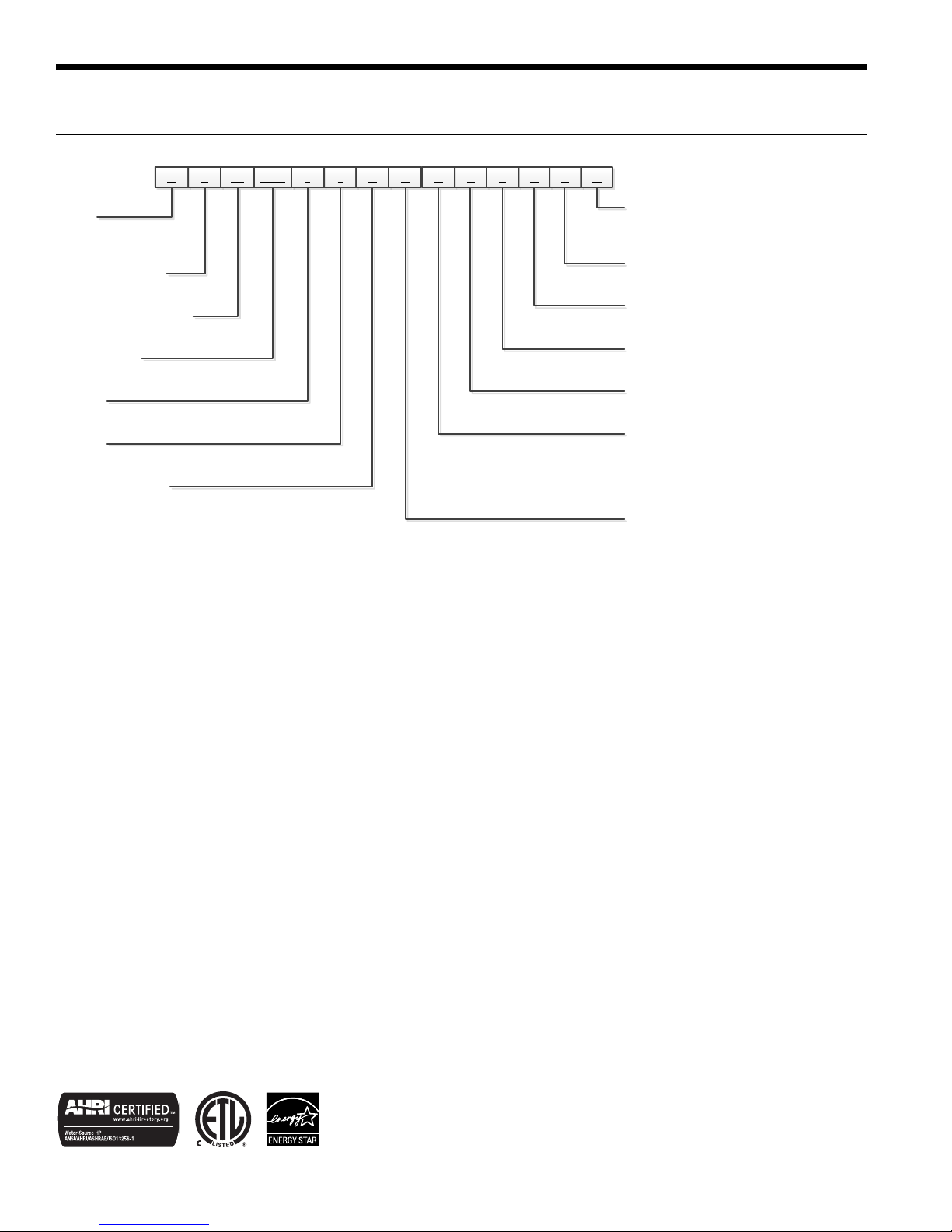
N S W 050 * 1 0 R C
3 4-6 7 8 9 10 11
Hot Water Option
1
IntelliStart®
N – None
A – IntelliStart
Controls Option
S – Microprocessor
Future Option
0 – Standard
Future
Option
S – Standard
Future Option
S – Standard
Water Coil Option
2
Reversible Option
Rev.:
S
12
21
S 0 S N
13 14 15
16
Model Nomenclature
Model
N – Envision Hydronic
Heat Pump
Compressor Type
S – Single Speed
Cabinet Configuration
W – Water-to-Water
Unit Capacity
018, 025, 040, 050, 060, 070
Vintage
* - Factory Use Only
Voltage
1 – 208-230/60/1
0 – No Hot Water Generation
2 – Hot Water Generation
NOTES: 1 – Available on 040, 050, 060, and 075 only. Hot water generator requires field installed external pump kit.
2 – NSW018 and NSW025 heating only models are available only with copper double wall vented load coax for potable water.
C – Copper
N - CuproNickel
L – Source CuproNickel & Load Copper
S – Source Copper & Load CuproNickel
H – Heating Only
R – Reversible
11 July 2013D
All Envision Series product is safety listed under UL1995 thru ETL and performance
listed with AHRI in accordance with standard 13256-1. The Envision Series is also
ENERGY STAR
®
rated.
4
General Installation Information
NSW INSTALLATION MANUAL
Safety Considerations
Installing and servicing air conditioning and heating
equipment can be hazardous due to system pressure and
electrical components. Only trained and qualified service
personnel should install, repair or service heating and air
conditioning equipment. When working on heating and
air conditioning equipment, observe precautions in the
literature, tags and labels attached to the unit and other
safety precautions that may apply.
Follow all safety codes. Wear safety glasses and work
gloves. Use quenching cloth for brazing operations. Have
fire extinguisher available for all brazing operations.
NOTE: Before installing, check voltage of unit(s) to ensure
proper voltage.
WARNING: Before performing service or
maintenance operations on the system, turn off
main power switches to the unit. Electrical shock
could cause serious personal injury.
Process Water Applications
For process water applications, it is recommended that
a secondary load heat exchanger be installed to prevent
corrosion to the unit’s primary coaxial coil. In situations
where scaling could be heavy or where biological growth
such as iron bacteria will be present, a closed loop system is
recommended. Over a period of time, ground water unit heat
exchanger coils may lose heat exchange capability due to a
buildup of mineral deposits. These can be cleaned only by
a qualified service mechanic as special pumping equipment
and solutions are required. Never use flexible hoses with a
smaller inside diameter than that of water connections.
WARNING: To avoid equipment damage, do not
leave the system filled in a building without heat
during cold weather, unless adequate freeze
protection levels of antifreeze are used. Heat
exchangers do not fully drain and will freeze
unless protected, causing permanent damage.
Unit Location
Provide sufficient room to make water and electrical
connections. If the unit is located in a confined space,
provisions must be made for unit servicing. Locate the
unit in an indoor area that allows easy removal of the
access panels and has enough space for service personnel
to perform maintenance or repair. These units are not
approved for outdoor installation and, therefore, must be
installed inside the structure being conditioned. Do not
locate units in areas subject to freezing conditions.
WARNING: Do not store or install units in
corrosive environments or in locations subject
to temperature or humidity extremes (e.g. attics,
garages, rooftops, etc.). Corrosive conditions and
high temperature or humidity can significantly
reduce performance, reliability, and service life.
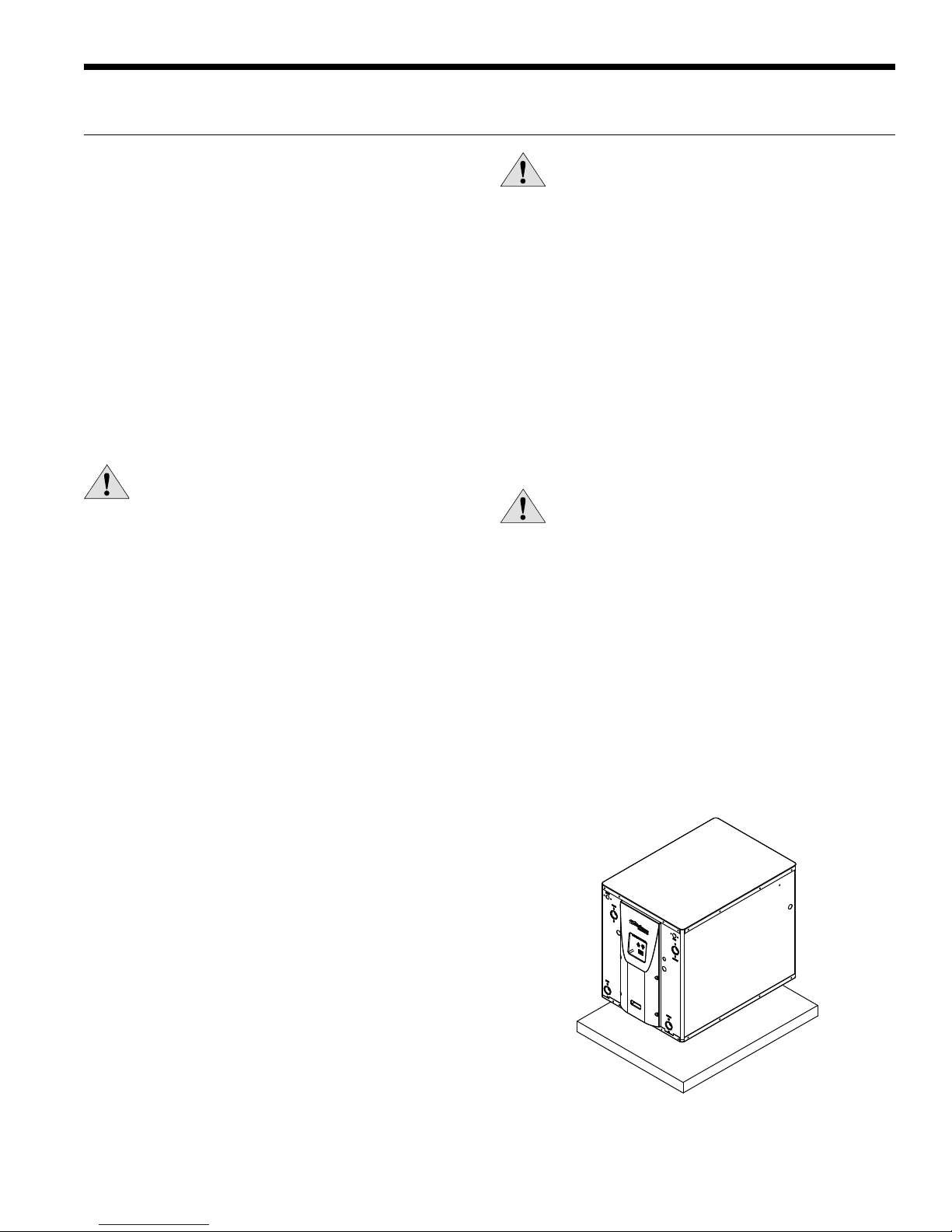
Mounting Units
Prior to setting the unit in place, remove and discard the
compressor hold down shipping bolt located at the front of
the compressor mounting bracket.
Units should be mounted level on a vibration absorbing pad
slightly larger than the base to provide isolation between
the unit and the floor. It is not necessary to anchor the unit
to the floor. Allow access to the front, back, and side access
panels for servicing.
Moving and Storage
Move units in the normal “Up” orientation as indicated by
the labels on the unit packaging. When the equipment
is received, all items should be carefully checked against
the bill of lading to ensure that all crates and cartons
have been received in good condition. Examine units for
shipping damage, removing unit packaging if necessary
to properly inspect unit. Units in question should also
be internally inspected. If any damage is observed, the
carrier should make the proper notation on delivery receipt
acknowledging the damage. Units are to be stored in a
location that provides adequate protection from dirt, debris
and moisture.
DWP`ObW]\>OR;]c\bW\U
5
NSW INSTALLATION MANUAL
Water Quality
General
NSW water-to-water heat pumps may be successfully
applied in a wide range of residential and light commercial
applications. It is the responsibility of the system designer
and installing contractor to ensure that acceptable water
quality is present and that all applicable codes have been
met in these installations. Failure to adhere to the guidelines
in the water quality table could result in loss of warranty.
Water Treatment
Do not use untreated or improperly treated water.
Equipment damage may occur. The use of improperly
treated or untreated water in this equipment may result in
scaling, erosion, corrosion, algae or slime. The services of a
qualified water treatment specialist should be engaged to
determine what treatment, if any, is required. The product
warranty specifically excludes liability for corrosion,
erosion or deterioration of equipment.
The heat exchangers and water lines in the units are copper
or cupronickel tube. There may be other materials in the
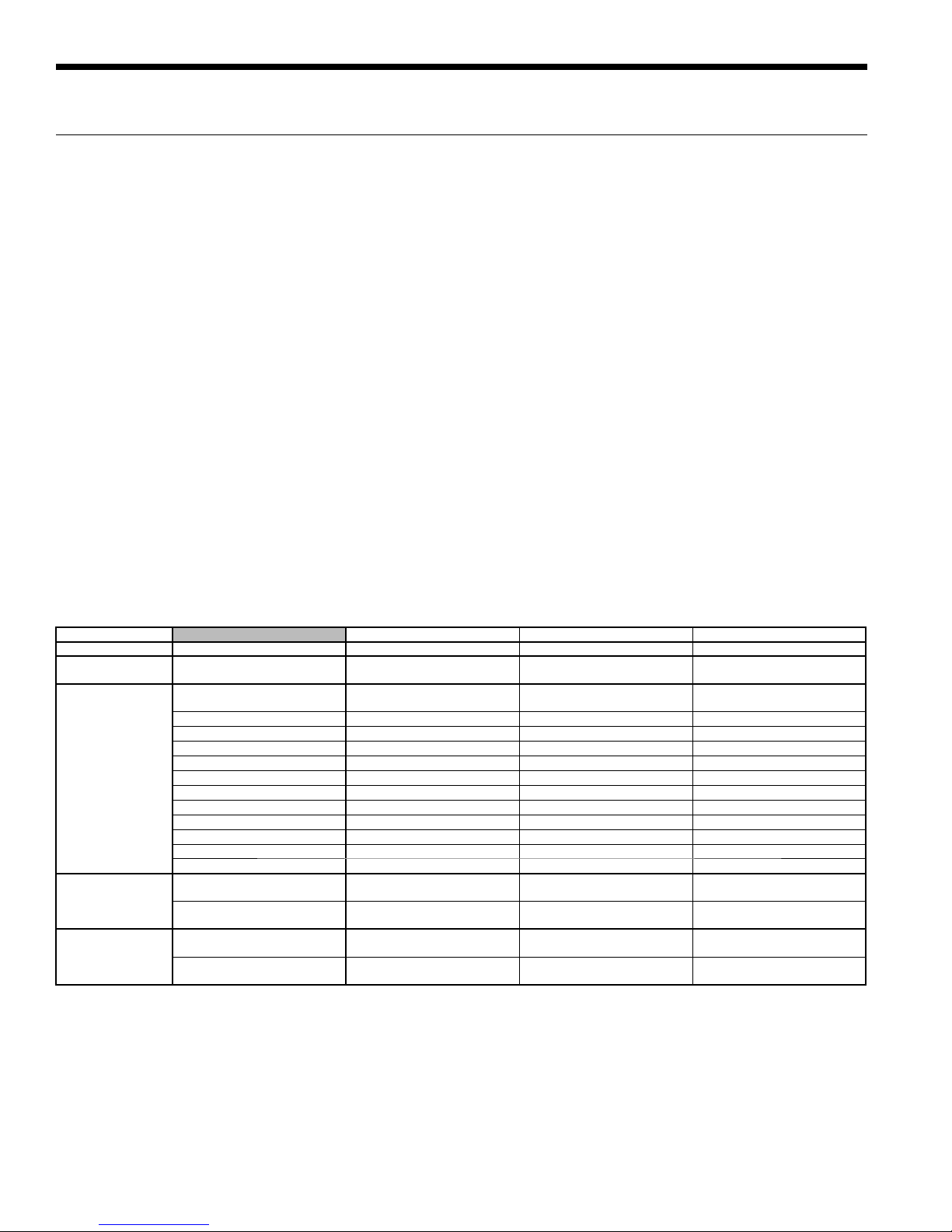
Water Quality Guidelines
building’s piping system that the designer may need to take
into consideration when deciding the parameters of the
water quality.
If an antifreeze or water treatment solution is to be used,
the designer should confirm it does not have a detrimental
effect on the materials in the system.
Contaminated Water
In applications where the water quality cannot be held to
prescribed limits, the use of a secondary or intermediate
heat exchanger is recommended to separate the unit from
the contaminated water.
The following table outlines the water quality guidelines
for unit heat exchangers. If these conditions are exceeded,
a secondary heat exchanger is required. Failure to supply
a secondary heat exchanger where needed will result in a
warranty exclusion for primary heat exchanger corrosion
or failure.
Material Copper 90/10 Cupronickel 316 Stainless Steel
pH Acidity/Alkalinity
Scaling
Corrosion
Iron Fouling
(Biological Growth)
Erosion
NOTES: Grains = ppm divided by 17
mg/L is equivalent to ppm
Calcium and
Magnesium Carbonate
Hydrogen Sulfide
Chlorine Less than 0.5 ppm Less than 0.5 ppm Less than 0.5 ppm
Chlorides Less than 20 ppm Less than 125 ppm Less than 300 ppm
Carbon Dioxide Less than 50 ppm 10 - 50 ppm 10 - 50 ppm
Ammonia Less than 2 ppm Less than 2 ppm Less than 20 ppm
Ammonia Chloride Less than 0.5 ppm Less than 0.5 ppm Less than 0.5 ppm
Ammonia Nitrate Less than 0.5 ppm Less than 0.5 ppm Less than 0.5 ppm
Ammonia Hydroxide Less than 0.5 ppm Less than 0.5 ppm Less than 0.5 ppm
Ammonia Sulfate Less than 0.5 ppm Less than 0.5 ppm Less than 0.5 ppm
Total Dissolved Solids (TDS) Less than 1000 ppm 1000 - 1500 ppm 1000 - 1500 ppm
LSI Index +0.5 to -0.5 +0.5 to -0.5 +0.5 to -0.5
Iron, FE
Bacterial Iron Potential
Iron Oxide
Suspended Solids
Threshold Velocity
(Fresh Water)
Less than 0.5 ppm (rotten egg
Sulfates Less than 125 ppm Less than 125 ppm Less than 200 ppm
2
+ (Ferrous)
smell appears at 0.5 ppm)
Less than 1 ppm, above this
level deposition will occur
Less than 10 ppm and filtered
for max. of 600 micron size
7 - 9 7 - 9 7 - 9
(Total Hardness)
less than 350 ppm
< 0.2 ppm < 0.2 ppm < 0.2 ppm
< 6 ft/sec < 6 ft/sec < 6 ft/sec
(Total Hardness)
less than 350 ppm
10 - 50 ppm Less than 1 ppm
Less than 1 ppm, above this
level deposition will occur
Less than 10 ppm and filtered
for max. of 600 micron size
(Total Hardness)
less than 350 ppm
Less than 1 ppm, above this
level deposition will occur
Less than 10 ppm and filtered
for max. of 600 micron size
2/22/12
6
Field Connected Water Piping
NSW INSTALLATION MANUAL
General
Each unit is equipped with captive FPT water connections
to eliminate ‘egg-shaping’ from use of a backup wrench.
For making the water connections to the unit, a Teflon tape
thread sealant is recommended to minimize internal fouling
of the piping. Do not over tighten connections. All supply and
return water piping should be insulated to prevent excess
condensation from forming on the water lines.
NOTE: Units are factory run-tested using propylene
glycol. Prior to connecting piping to unit, thoroughly flush
heat exchangers.
The piping installation should provide service personnel with
the ability to measure water temperatures and pressures.
The water lines should be routed so as not to interfere with
access to the unit. The use of a short length of high pressure
hose with a swivel type fitting may simplify the connections
and prevent vibration. Optional stainless steel hose kits are
available as an accessory item.
Before final connection to the unit, the supply and return
hose kits must be connected, and the system flushed
to remove dirt, piping chips and other foreign material.
Normally, a combination balancing and close-off (ball) valve
is installed at the return, and a rated gate or ball valve is
installed at the supply. The return valve can be adjusted to
obtain the proper water flow. The valves allow the unit to be
removed for servicing.
to-water heat exchanger (See Pressure Drop Table for water
flow and pressure drop information). Normally about 3 GPM
flow rate per ton of cooling capacity (2.25 GPM per ton
minimum) is needed. Both source as well as load fluid piping
must be at least as large as the unit connections on the heat
pump (larger on long runs).
Never use flexible hoses of a smaller inside diameter than
that of the water connection on the unit and limit hose length
to 10 ft. per connection. Check carefully for water leaks.
CAUTION: Water piping exposed to outside
temperature may be subject to freezing.
Open Loop Well Water Systems
Always maintain water pressure in the heat exchanger by
placing water control valves at the outlet of the unit. Use
a closed bladder type expansion tank to minimize mineral
deposits. Ensure proper water flow through the unit by
checking pressure drop across the heat exchanger and
comparing it to the figures in the pressure drop table.
Normally, about 2 GPM flow rate per ton of cooling capacity
is needed in open loop systems, (1.5 GPM per ton minimum if
entering source temperature is above 50°F [10°C].
Some water control valves draw their power directly from
the unit’s 24V transformer and can overload and possibly
burn out the transformer. Check total VA draw of the water
valve(s) and ensure it is under 40 VA.
The proper water flow must be delivered to each unit
whenever the unit heats or cools. To assure proper flow,
the use of pressure/temperature ports is recommended
to determine the flow rate. These ports should be located
adjacent to the supply and return connections on the unit.
The proper flow rate cannot be accurately set without
measuring the water pressure drop through the refrigerant-
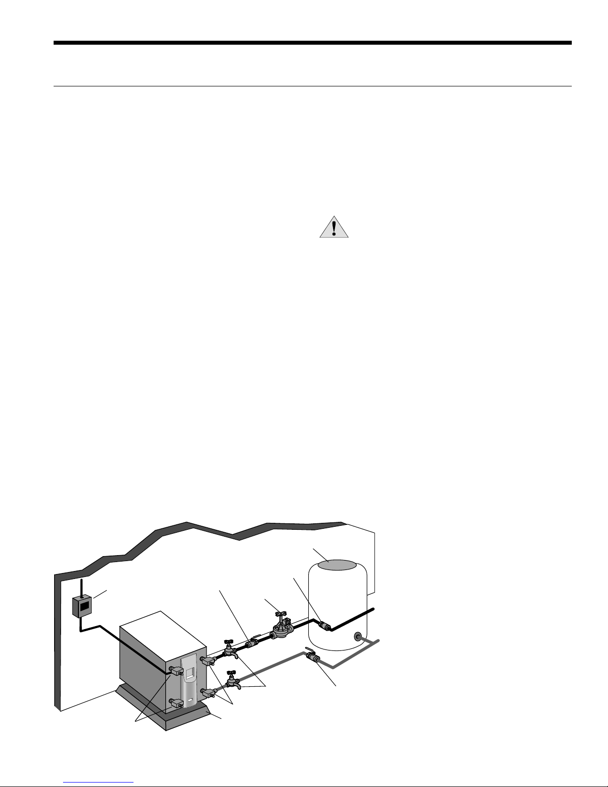
Typical Open Loop Installation
Rubber Bladder
Expansion Tank
Flow Regulator Valve
Line Voltage
Disconnect
Load Liquid
Connections
Shut-off Valve
(to isolate solenoid
valve while acid
flushing)
Solenoid
Valve
Boiler Drains for
HX Flushing
P/T Plugs
Vibration Absorbing
Mesh or Air Pad
Discharge water from a heat pump can be disposed of in
various ways depending on local building codes (i.e. recharge
well, storm sewer, drain field, adjacent stream or pond,
etc.). Most local codes restrict the use of sanitary sewer for
disposal. Consult your local building and zoning departments
to ensure compliance in your area.
Water Out
Water In
Shut-off
Valve
NOTE: Valves and boiler drains must be installed
so the heat exchanger can be acid flushed.
7
NSW INSTALLATION MANUAL
Field Connected Water Piping cont.
Earth Coupled Systems with Flow Center
Once piping is completed between the unit, flow center
and the earth loop, final purging and charging of the loop
is needed. A flush cart (at least a 1.5 HP or 1.12 kW pump)
is needed to achieve adequate flow velocity in the loop to
purge air and dirt particles from the loop itself. Antifreeze
solution is used in most areas to prevent freezing. Maintain
the pH in the 7.6-8.2 range for final charging.
Flush the system adequately to remove as much air as
possible. Then, pressurize the loop to a static pressure of
50-75 psi [345-517 kPa]. This is normally adequate for good
system operation. Ensure that the flow center provides
adequate flow through the unit by checking pressure drop
across the heat exchanger and by comparing it to the
figures shown in the Pressure Drop tables. Usually, 3 GPM/
ton [0.054 L/s/kW] L/s/kW or minimum 2.25 GPM/ton
[0.04 L/s/kW] of cooling capacity is needed in closed loop
earth-coupled applications
Potable Water Systems
The NSW018 and NSW025 models can be equipped to
provide domestic hot water generation. An optional
factory-installed hot water generator coil may be provided
with the NSW040, NSW050, NSW060, and NSW075 to
assist with this process.
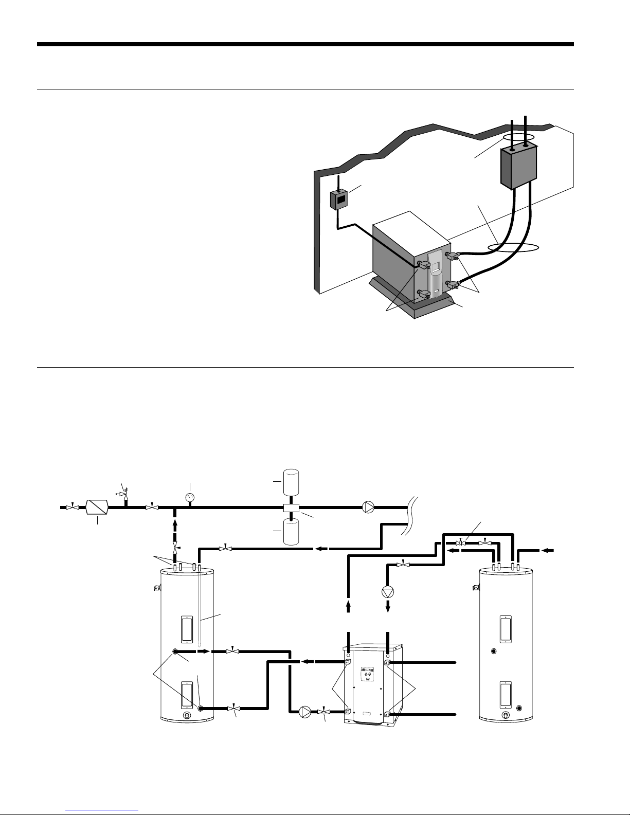
Typical Closed Loop Earth Coupled Installation
Earth Coupled Loop
Piping with Insulation
Line Voltage
Disconnect
Unit Connector Kits
with Insulation
P/T Plugs
Load Liquid
Connections
Vibration Absorbing
Mesh or Air Pad
Suggested Domestic Water Heater Hookup
30 psi
RELIEF VALVE
Back Flow Preventer /
Pressure Relief Valve
Dielectric
Unions
Dielectric
Unions
NOTES:
* A 30 psi pressure relief valve (Part No: SRV30) should be used in
hydronic applications.
** Vent valve or P/T port at highest point in return line prior to ball valve.
Pressure
Gauge
GEO
STORAGE
TANK
1-1/2 in.
FPT
Dip Tube
Expansion
Tank
Ball Valve
Air
Vent
Air
Separator
Ball Valve
LOAD PUMP
FROM
HWG
HWG
WaterFurnace
NSW Series
TO
HYDRONIC
PUMP
Source OUT
P/T PortsP/T Ports
Source IN
LOAD
HOT
(Piped in
series to
an electric
water heater)
Vent Valve/
P/T Port**
DOMESTIC
COLD
8
Potable Water Systems cont.
NSW INSTALLATION MANUAL
NOTES:
1) Unions and valves must be installed so that acid flushing
of the heat exchanger is possible.
2) Route thermistor wires to NSW. Remove yellow
thermistor wires on TB 3 and 4 from control box and
connect thermistor wires from geothermal storage tank.
Set the pump sampling (PS) in the set up of the control
board to continuously (C) sampling (reference Note 5 in
the Wiring Schematic).
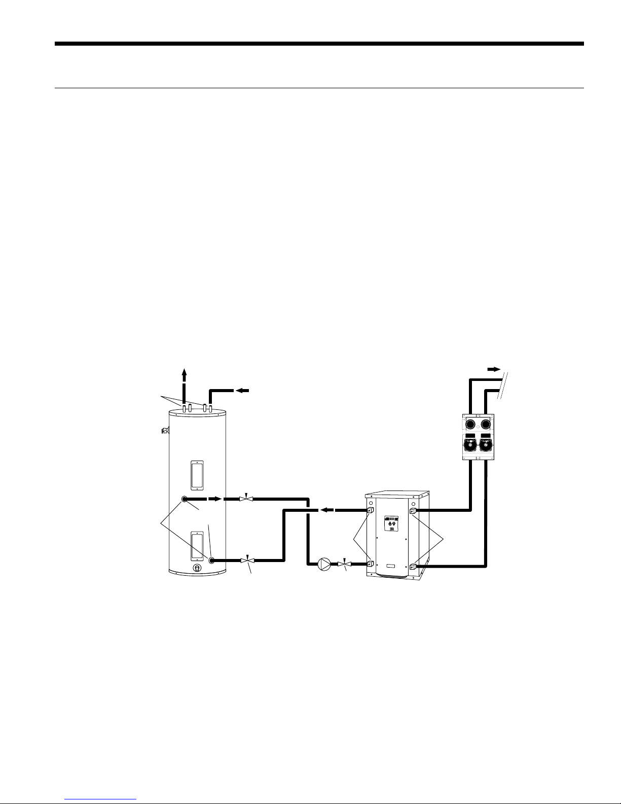
Alternate Hot Water Installation with
Direct Coupling to a Double Wall Unit
2WSZSQb`WQ
C\W]\a
6=B
1=:2
Hot Water Generator Connections
The heat reclaiming hot water generator coil is vented double-
wall copper construction and is suitable for potable water. To
maximize the benefits of the hot water generator a minimum
50-gallon water heater is recommended. For higher demand
applications, use an 80-gallon water heater as shown below or
two 50-gallon water heaters connected in a series. A geo storage
tank should not be used in this application unless it is plumbed
in a series with an electric water heater. The geo storage tank
is equipped with a single 4500 Watt element and will not be
able to provide adequate water heating if used as a standalone
water heater. Electric water heaters are recommended. Make
sure all local electrical and plumbing codes are met for installing
a hot water generator. The Envision NSW is not supplied with
an internal circulator. A DPK5 kit will need to be purchased to
connect to the hot water generator. The DPK5 kit is supplied with
installation instructions, circulator, tank adaptor and temperature
limit switch. Be sure to burp (vent) the pump. Open the screw
2 turns only in the end of the pump motor (if Grundfos
are used) to allow trapped air to be discharged and to ensure the
motor housing has been flooded.
:==>473:2
®
pumps
Þ
2WSZSQb`WQ
C\W]\a
4>B
0OZZDOZdS
EObS`4c`\OQS
53=B/<9
NOTES:
1) Unions and valves must be installed so that acid flushing
of the heat exchanger is possible.
2)
Make sure there is not a check valve in the diptube of
the tank.
3) Route thermistor wires to NSW. Remove yellow
thermistor wires on TB 3 and 4 from control box and
connect thermistor wires from geothermal storage tank.
Set the pump sampling (PS) in the set up of the control
board to continuously (C) sampling (reference Note 5 in
the Wiring Schematic).
4:=E13<B3@
>B>]`ba>B>]`ba
0OZZDOZdS
EObS`4c`\OQS
<AE&]`<AE #6SObW\U=\Zg
eWbV2]cPZSEOZZ:]OR1]Of
9

NSW INSTALLATION MANUAL
Hydronic Section
General guidelines are shown below for component
selection and design/installation criteria for the piping
system. Local codes supersede any recommendations in
this manual.
Shut Off/Flow Regulation Valves
Use full port ball valves or gate valves for component
isolation. If valves are going to be used frequently, ball
valves are recommended. Globe valves are designed for flow
regulation. Always install globe valves in the correct direction
(fluid should enter through the lower body chamber).
Check valves
Swing check valves must be installed in the horizontal
position with the bonnet of the valve upright. Spring check
valves can be mounted in any position. A flow check valve
is required to prevent thermo-siphoning (or gravity flow)
when the circulator pump is off or when there are two
circulators on the same system.
Storage (Buffer) Tank
A buffer tank is required for all hydronic heating systems
using Envision NSW heat pumps. The tank should be sized
to provide 2 gallons of storage capacity for every one
thousand Btuh’s of nominal heat pump capacity.
Pressure Relief Valve
Most codes require the use of a pressure relief valve if a
closed loop heat source can be isolated by valves. Even
if local code does not require this device, WaterFurnace
recommends its installation. If the pressure relief valve in
the buffer tank is not already rated at 30 psi (207 kPa)
maximum pressure, one must be installed. The pressure
relief valve should be tested at start up for operation. Note
that the waste pipe must be at least the same diameter
as the valve outlet (never reduce), and valves may not be
added to this pipe. The bottom of the pipe must terminate
at least 6” (15 cm) above the floor. If the piping is connected
to a drain, there must be an air gap.
0 psi (0 kPa), potentially causing pumps(s) failure. A valve
should be installed on each side of the pressure reducing
valve for servicing. Both valves should have tags reading
“Do not shut this valve under normal operation – service
valve only.”
Expansion Tanks
Expansion tanks are required on hydronic systems to help
absorb the pressure swings as the temperature in the
system fluctuates.
Elbows/Tees
Long radius elbows or two 45° elbows will lower pressure
drop. Standard tees have a greater restriction on the “T”
portion than tees designed with angled outlet ports.
Antifreeze
Antifreeze is required if any of the piping system is located
in areas subject to freezing.
Dielectric Unions
Dielectric unions are recommended whenever connecting
two dissimilar metals to one and other to prevent electrogalvanic corrosion.
When using the various types of hydronic heat distribution
systems, the temperature limits of the geothermal system
must be a major consideration. In new construction, the
distribution system can easily be designed with the
temperature limits in mind. In retrofits, care must be
taken to address the operating temperature limits of the
existing distribution system. The maximum storage tank
temperature for the Envision NSW is 130°F (54.4°C). Typical
in floor radiant systems require much lower temperatures,
typically 100°-115°F, which is ideal for the Envision NSW.
Backflow Prevention Check Valves
Most codes require backflow prevention check valves.
Note that a single check valve is not equal to a backflow
prevention check valve. Even if local code does not require
this device, WaterFurnace recommends its installation. This
is particularly important if the system will use antifreeze.
Pressure Reducing Valves or Feed Water Valves
This valve lowers the pressure from the make-up water line
to the system. Most are adjustable and directional. A “fast
fill” valve is required for initial filling of the system. Some
have screens, which must be cleaned after the initial filling.
If there is a restriction in the screen, the system could go to
10
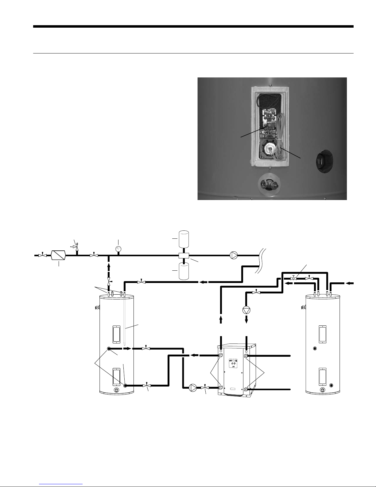
Hydronic Section cont.
NSW INSTALLATION MANUAL
Open the screw 2 turns only in the end of the pump motor
(if Grundfos
®
pumps are used) to allow trapped air to be
discharged and to ensure the motor housing has been flooded.
Route thermistor wires to NSW. Remove yellow thermistor
wires on TB 3 and 4 from control box and connect to red
thermistor wires from the top of the geothermal storage
tank. Set the pump sampling (PS) in the set up of the control
board to continuously (C) sampling (reference Note 5 in the
Wiring Schematic).
Adequate rate of flow (GPM) is very important to system
performance and long term reliability. Follow the guidelines
for recommended flow and pipe sizing in the NSW
recommendations table.
30 psi
RELIEF VALVE
Back Flow Preventer /
Pressure Relief Valve
Pressure
Gauge
Air
Vent
Expansion
Tank
WaterFurnace Geothermal Storage Tank Thermostat
and Thermistor
Synergy3D
Thermostat
NSW
Yellow Thermistor Wires Connected to TB (3 and 4) on
NSW Control Board
LOAD PUMP
HYDRONIC
Air
Separator
LOAD
Vent Valve/
P/T Port**
Dielectric
Unions
GEO
STORAGE
TANK
Dip Tube
1-1/2 in.
Dielectric
Unions
NOTES:
* A 30 psi pressure relief valve (Part No: SRV30) should be used in
hydronic applications.
** Vent valve or P/T port at highest point in return line prior to ball valve.
FPT
Ball Valve
Ball Valve
11
FROM
HWG
HWG
WaterFurnace
NSW Series
TO
PUMP
Source OUT
P/T PortsP/T Ports
Source IN
HOT
(Piped in
series to
an electric
water heater)
COLD
DOMESTIC
NSW INSTALLATION MANUAL
Accessories and Options
Earth Loop Pump Kit (Field Installed)
A specially designed one or two-pump module provides all
liquid fl ow, fi ll and connection requirements for independent
single unit systems (230/60/1 only). The one-pump module
is capable of 20 feet of head at 16.0 GPM, while the twopump module is capable of 40 feet of head at 16.0 GPM.
Hot Water Generator (Factory Installed, NSW040,
NSW050, NSW060, and NSW075 Only)
An optional heat reclaiming hot water generator coil
constructed of vented double-wall copper construction
suitable for potable water is available. The coil is factory
mounted inside the unit. A DPK5 pump kit is required (fi eld
installed), which includes a DHW tank connection and a
temperature limit pump shutoff.
Load-side Pump Kit (Field Installed)
Four (4) load pump kits are available to provide all liquid flow
requirements for independent single unit systems (230/60/1
only). WaterFurnace part number 24S516-10 (Gr undfos
UPS15-42RU) is a composite body pump. EWPK2 (G rundfos
UP26-64BF) is a bronze body pump. Bronze or composite
body pumps should be used when water conditions exist that
are not compatible with cast iron or for applications such as
domestic water heating. WaterFurnace part number EWPK1
and EWPK3 come with a cast iron body pump (Grundfos
UP26-99F) that can be used for hydronic heating applications.
Calculate the system pressure drop then refer to the pump
curves to select the proper pump. All four of the WaterFurnace
pump kits can be used for hydronic heating applications as long
as they meet the fl ow requirements. If the fl ow requirements
are outside the pump curve, an alternate pump will need to be
obtained to maintain the necessary fl ow.
IntelliStart
®
The optional IntelliStart single phase soft starter will reduce
the normal start current (LRA) by 60-70%. This allows the
heat pump to go off-grid. Using IntelliStart also provides a
substantial reduction in light fl icker, reduces start-up noise,
and improves the compressor’s start behavior. IntelliStart is
available in a fi eld retrofi t kit (WaterFurnace part number
IS60RKL or IS60RKS) or as a factory installed option for all
Envision and Synergy3D units.
Water Connection Kits (Field Installed)
Water connection kits are available to facilitate loop side
and load side water connections.
• MA4FPT - Forged brass 1” MPT x 1” FPT square street
elbow with P/T plug for NSW018-NSW040 water
side connections
• MA5FPT - Forged brass 1.25” MPT x 1.25” FPT square
street elbow with P/T plug for NSW050-NSW075 water
side connections
• 2-HVAC-1x24 - 1 inch x 24 inch stainless steel braided
hose kit
• 2-HVAC-1 1/4x24 - 1 1⁄4 inch x 24 inch stainless steel
braided hose kit
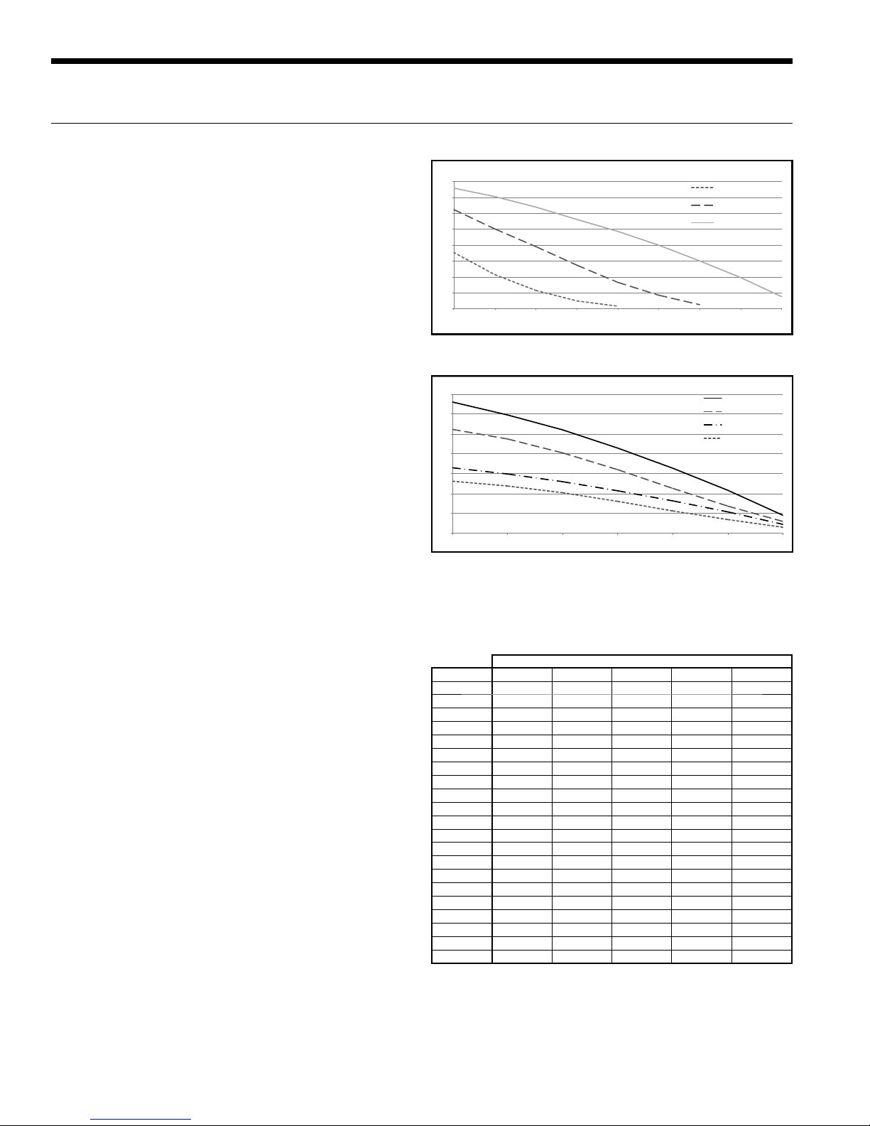
UPS15-42RU Three-Speed Pump Curve
16
14
12
10
8
Feet of Head
6
4
2
0
0 2 4 6 8 10 12 14 16
UPS15-42RU 3-Speed Pump
UPS15-42RU (Low)
UPS15-42RU (Med)
UPS15-42RU (High)
GPM
UP26-64BF and UP26-99F Single and Two Pump Curve
70
60
50
40
30
Feet of Head
20
10
0
0 5 10 15 20 25 30
UP26-64BF & UP26-99F Single and Two Pump
GPM
UP26-99F (2 Pumps)
UP26-64BF (2 Pumps)
UP26-99F (1 Pump)
UP26-64BF (1 Pump)
NOTE: Never use piping smaller than 1 inch. Limit length of
pipe to 50 feet or less.
Type L Copper Pressure Loss
Ft of Hd per 100 ft
GPM 3/4 1 1-1/4 1-1/2 2
2
3
4
5
6
7
8
9
10
12
14
16
18
20
22
25
30
35
40
45
50
1.5
3.2
5.5 1.4
8.5 2.1
Type L Copper Tube
2.9 1.1
3.9 1.4
5.0 1.8
6.1 2.3 0.9
7.5 2.8 1.1
3.9 1.6
5.2 2.1
6.6 2.7
8.2 3.4
10.0 4.1 1.1
5.0 1.3
6.3 1.6
2.2
2.9
3.8
4.7
5.7
NOTE: Standard piping practice limits pressure drop to 4
feet of hd per 100 feet in 2 inch and larger pipe.
12
Accessories and Options cont.
NSW INSTALLATION MANUAL
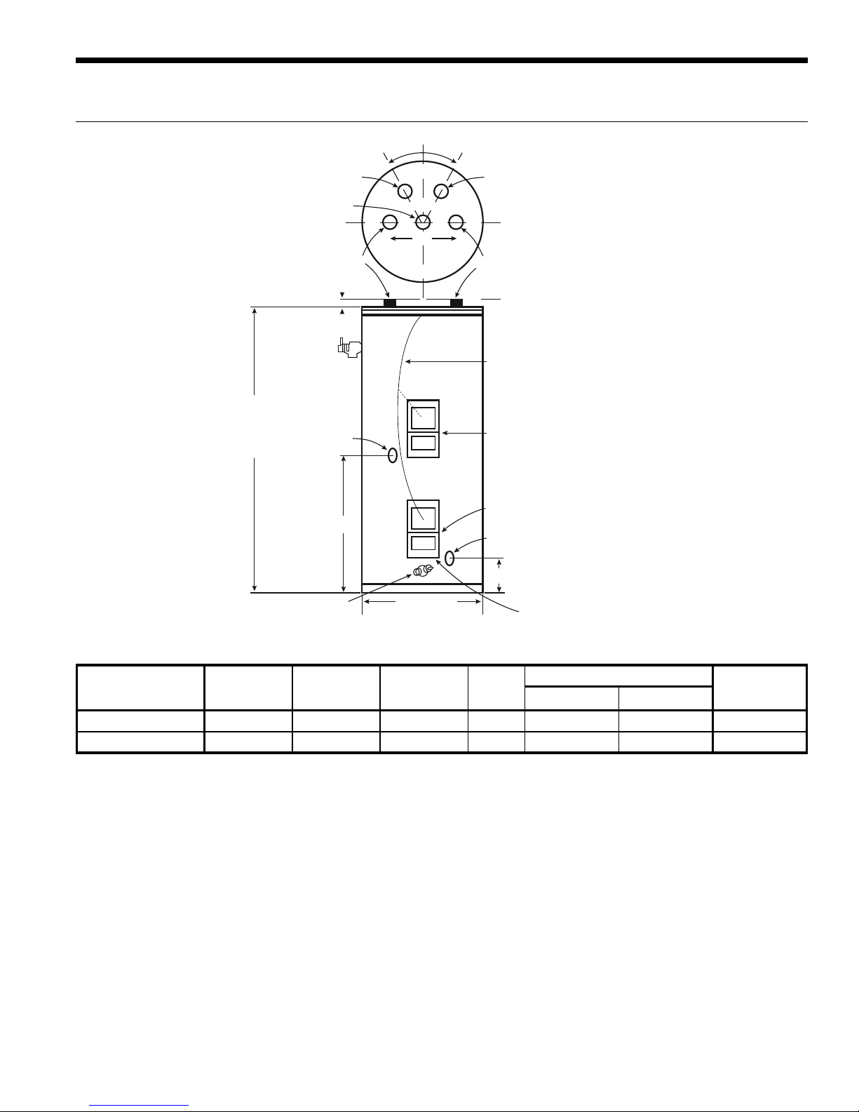
Geo Storage Tank Dimensions
PRIMARY ANODE
3/4˝ HOT OUTLET
w/14˝ SECONDARY ANODE
HEIGHT
Optional “To Geo”
Connection Shipped with
1-1/2˝ Pipe Plug Installed
From Geo
1˝ x 3˝ Nipple
39˝ - 80 Gallon
42˝ - 119 Gallon
Approx. 1˝
T & P
VALVE
35-3/4˝
°
3
0
0
3
8˝
°
To Geo 59˝ Dip Tube
w/1˝ x 3˝ Nipple
COLD INLET
3/4˝
52˝ DIP TUBE
Red Wire attached
to Thermistor or Thermostat
for Top Exit
Element Location
Lower Sensor Thermistor (12P541-01)
to be used by Water to Water Units
Optional “From Geo” Connection
Shipped with 1-1/2˝ Pipe Plug Installed
MODEL
NUMBER
GEO-STORAGE-80
GEO-STORAGE-120
5-1/4˝
DRAIN VALVE
GALLON
CAPACITY
80 4500 1 16 63-1/4 24 204
119 4500 1 16 63-1/4 28 311
ELEMENT
WATTAGE
(240 VOLT)
DIAMETER
NUMBER
OF
ELEMENTS
R
VALUE
Lower Thermostat to be used
with Synergy units
DIMENSIONS IN INCHES APPROX.
HEIGHT DIAMETER
SHIPPING
WEIGHT (lbs.)
13
NSW INSTALLATION MANUAL
Electrical Data
Model
018
025
040
050
060
075
NOTES: All fuses type “D” time delay (or HACR circuit breaker in USA).
Source pump amps shown are for up to a 1/2 HP pump.
Load pumps amps shown are for small circulators.
*LRA with optional IntelliStart installed (208-230/60/1).
Rated
Voltage
208-230/60/1 187/253 9.0 48.0 17.0 1.8 5.4 16.2 18.5 30
208-230/60/1 187/253 13.5 61.0 21.4 1.8 5.4 20.7 24.1 35
208-230/60/1 187/253 20.0 115.0 40.3 1.8 5.4 27.2 32.2 50
208-230/60/1 187/253 26.4 134.0 46.9 1.8 5.4 33.6 40.2 60
208-230/60/1 187/253 30.1 145.0 50.8 1.8 5.4 37.3 44.8 70
208-230/60/1 187/253 26.9 145.0 50.8 1.8 5.4 34.1 40.8 60
Voltage
Min/Max
Compressor
RLA LRA LRA*
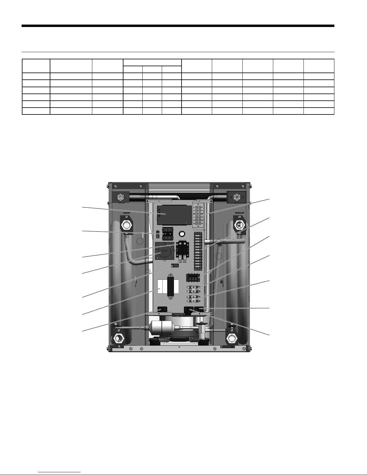
NSW Control Box
Optional IntelliStart
Power Block
IntelliStart Only
Load
Pump
Source
Pump
Total Unit
FLA
Min Ckt
Amp
Maximum
Fuse/HACR
Terminal Board
Terminal Power Strip
Power Block
7/26/13
Compressor Contactor
Run Capacitor
(Single Phase Only)
Ground Lug
Transformer
Load Pump Relay
Load Pump Fuse Block
Source Pump Fuse Block
Reversing Valve Relay
Source Pump Relay
14
 Loading...