

Page 1
NXW 10 to 50 Tons
Commercial Reversible Chiller - 60 Hz
Installation Information
Water Piping Connections
Electrical Data
Microprocessor Control
Startup Procedures
Preventive Maintenance
NXW Reversible Chiller Installation Manual
IM2502WN 06/14
Page 2

Page 3

Table of Contents
Model Nomenclature . . . . . . . . . . . . . . . . . . . . . . . . . . . . . . . . . . . . . . . . . . . . . . . . . . . . . . . . . . . . . . 4
General Installation Information . . . . . . . . . . . . . . . . . . . . . . . . . . . . . . . . . . . . . . . . . . . . . . . . . . 5-6
NXW REVERSIBLE CHILLER INSTALLATION MANUAL
Physical Dimensions
Physical Data . . . . . . . . . . . . . . . . . . . . . . . . . . . . . . . . . . . . . . . . . . . . . . . . . . . . . . . . . . . . . . . . . . . . . 9
Field Connected Water Piping. . . . . . . . . . . . . . . . . . . . . . . . . . . . . . . . . . . . . . . . . . . . . . . . . . . 10-11
Typical Piping . . . . . . . . . . . . . . . . . . . . . . . . . . . . . . . . . . . . . . . . . . . . . . . . . . . . . . . . . . . . . . . . . . . 12
Water Quality . . . . . . . . . . . . . . . . . . . . . . . . . . . . . . . . . . . . . . . . . . . . . . . . . . . . . . . . . . . . . . . . . . . 13
System Cleaning and Flushing. . . . . . . . . . . . . . . . . . . . . . . . . . . . . . . . . . . . . . . . . . . . . . . . . . . . . 14
Electrical Data . . . . . . . . . . . . . . . . . . . . . . . . . . . . . . . . . . . . . . . . . . . . . . . . . . . . . . . . . . . . . . . . .15-16
Wiring Schematics . . . . . . . . . . . . . . . . . . . . . . . . . . . . . . . . . . . . . . . . . . . . . . . . . . . . . . . . . . . . .17-18
Field Wiring and Control Setup. . . . . . . . . . . . . . . . . . . . . . . . . . . . . . . . . . . . . . . . . . . . . . . . . 19-20
Control Features. . . . . . . . . . . . . . . . . . . . . . . . . . . . . . . . . . . . . . . . . . . . . . . . . . . . . . . . . . . . . . 21-22
Sequence of Operation . . . . . . . . . . . . . . . . . . . . . . . . . . . . . . . . . . . . . . . . . . . . . . . . . . . . . . . . . . . 23
Inputs and Outputs Configuration . . . . . . . . . . . . . . . . . . . . . . . . . . . . . . . . . . . . . . . . . . . . . . . . .24
Networking Protocol . . . . . . . . . . . . . . . . . . . . . . . . . . . . . . . . . . . . . . . . . . . . . . . . . . . . . . . . . . . . .24
Unit Display and Interface. . . . . . . . . . . . . . . . . . . . . . . . . . . . . . . . . . . . . . . . . . . . . . . . . . . . . .25-26
Reference Calculations . . . . . . . . . . . . . . . . . . . . . . . . . . . . . . . . . . . . . . . . . . . . . . . . . . . . . . . . . . . 27
Legend . . . . . . . . . . . . . . . . . . . . . . . . . . . . . . . . . . . . . . . . . . . . . . . . . . . . . . . . . . . . . . . . . . . . . . . . . 27
Unit Startup . . . . . . . . . . . . . . . . . . . . . . . . . . . . . . . . . . . . . . . . . . . . . . . . . . . . . . . . . . . . . . . . . . . . .27
. . . . . . . . . . . . . . . . . . . . . . . . . . . . . . . . . . . . . . . . . . . . . . . . . . . . . . . . . . . . . 7-8
Operating Parameters . . . . . . . . . . . . . . . . . . . . . . . . . . . . . . . . . . . . . . . . . . . . . . . . . . . . . . . . . . . .28
Pressure Drop . . . . . . . . . . . . . . . . . . . . . . . . . . . . . . . . . . . . . . . . . . . . . . . . . . . . . . . . . . . . . . . . . . .30
Compressor / Thermistor Resistance . . . . . . . . . . . . . . . . . . . . . . . . . . . . . . . . . . . . . . . . . . . . . . . 31
Operating Limits . . . . . . . . . . . . . . . . . . . . . . . . . . . . . . . . . . . . . . . . . . . . . . . . . . . . . . . . . . . . . . . . . 31
Troubleshooting . . . . . . . . . . . . . . . . . . . . . . . . . . . . . . . . . . . . . . . . . . . . . . . . . . . . . . . . . . . . . . . . . 32
Heating and Cooling Cycle Analysis. . . . . . . . . . . . . . . . . . . . . . . . . . . . . . . . . . . . . . . . . . . . . . . .33
Troubleshooting Form . . . . . . . . . . . . . . . . . . . . . . . . . . . . . . . . . . . . . . . . . . . . . . . . . . . . . . . . . . . .34
Factory Start-up . . . . . . . . . . . . . . . . . . . . . . . . . . . . . . . . . . . . . . . . . . . . . . . . . . . . . . . . . . . . . . 35-37
Preventive Maintenance . . . . . . . . . . . . . . . . . . . . . . . . . . . . . . . . . . . . . . . . . . . . . . . . . . . . . . . . . .38
Replacement Fuse Chart. . . . . . . . . . . . . . . . . . . . . . . . . . . . . . . . . . . . . . . . . . . . . . . . . . . . . . . . . . 39
Service Parts List . . . . . . . . . . . . . . . . . . . . . . . . . . . . . . . . . . . . . . . . . . . . . . . . . . . . . . . . . . . . . 39-41
Revision Guide. . . . . . . . . . . . . . . . . . . . . . . . . . . . . . . . . . . . . . . . . . . . . . . . . . . . . . . . . . . . . . . . . . .42
Page 4
ENVISION2 NXW REVERSIBLE CHILLER INSTALLATION MANUAL
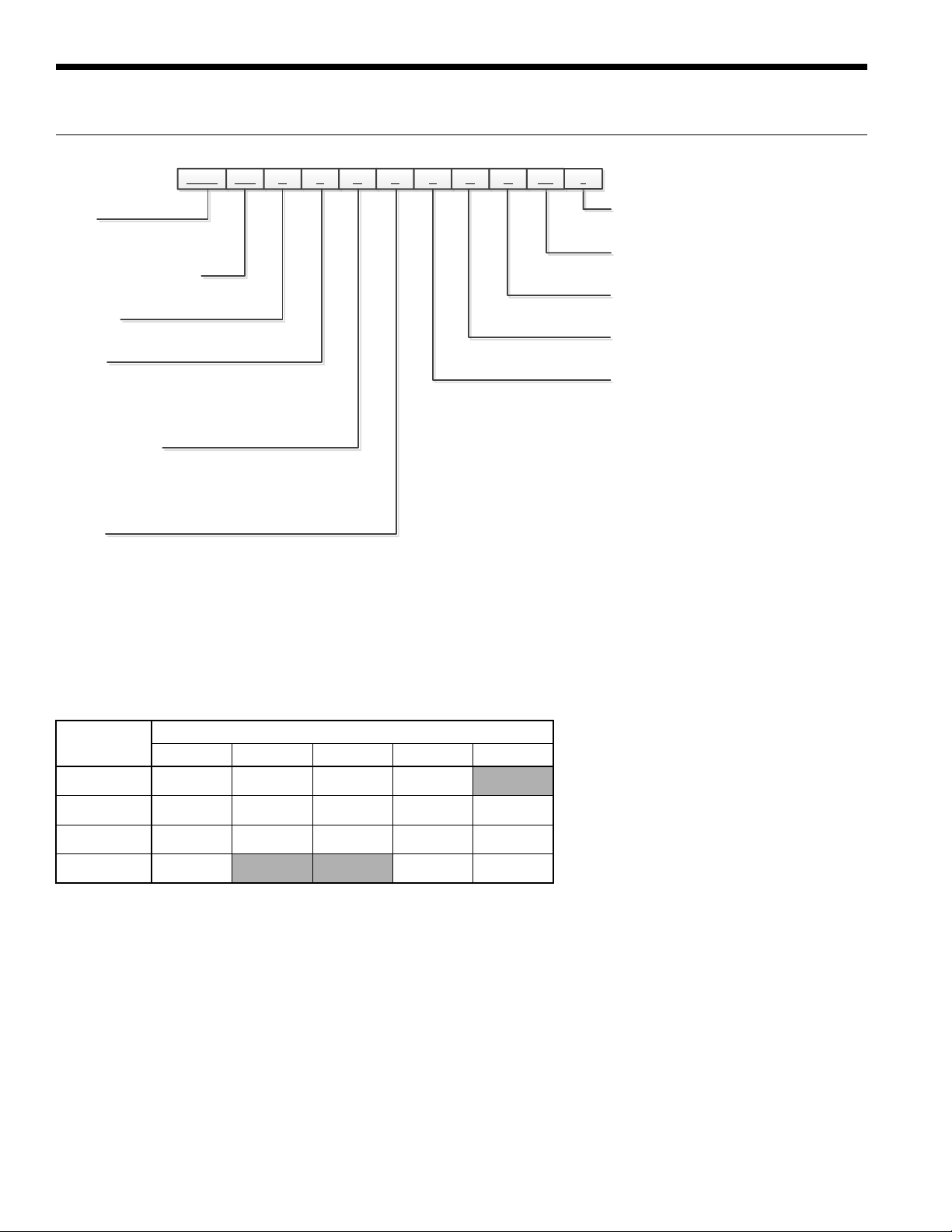
NXW 120 R 3 A E 8 N N
1-3 4-6 7 8 11 12 13
Vintage
Non-Standard Options
Future Option
Future Option
Controls
Rev.:
SS
14-15*16
9 10
Model Nomenclature
Model
NXW – Envision
Reversible Chiller
Unit Capacity (MBTUH)
120, 180, 240, 360, 600
Operation
R - Reversible
Voltage
3 – 208-230/60/3
4 – 460/60/3
5 – 575/60/3
8 – 380/60/3
Phase Protection
A – Non-Fused Disconnect, Phase Guard
B – Non-Fused Disconnect, IntelliStart®
C – Fused Disconnect, Phase Guard
D – Fused Disconnect, IntelliStart
Chassis
E – Enclosed
P – Enclosed with Pressure Gauges
Notes:
See electrical availability table for detailed offering by voltage
2
Series
* - Factory Use Only
SS - Standard
N – Future Use
N – Future Use
8 – FX10 without Communication,
with User Interface
9 – FX10 with Open N2 Communication
Card with User Interface
0 – FX10 with Lonworks Communication
Card with User Interface
3 – FX10 with BacNet Communication
Card with User Interface
14 February 2014D
Voltage Availability
Voltage
208-230/60/3
460/60/3
575/60/3
380/60/3
Legend:
NA = Not Available
120 180 240 360 600
•• ••
•• •• •• • •
•••••
••
NA NA
Model
• = Voltage available in this size
•• = Voltage and IntelliStart available in this size
NA
••
03/05/14
4
Page 5
General Installation Information
ENVISION2 NXW REVERSIBLE CHILLER INSTALLATION MANUAL
Safety Considerations
Installing and servicing air conditioning and heating
equipment can be hazardous due to system pressure and
electrical components. Only trained and qualified service
personnel should install, repair or service heating and air
conditioning equipment. When working on heating and
air conditioning equipment, observe precautions in the
literature, tags and labels attached to the unit and other
safety precautions that may apply.
Follow all safety codes. Wear safety glasses and work
gloves. Use quenching cloth for brazing operations. Have
fire extinguisher available for all brazing operations.
NOTE: Before installing, check voltage of unit(s) to ensure
proper voltage.
WARNING: Before performing service or
maintenance operations on the system, turn off
main power switches to the unit. Electrical shock
could cause serious personal injury.
Application
Units are not intended for heating domestic (potable water)
by direct coupling. If used for this type of application, a
secondary heat exchanger must be used.
Unit Location
Provide sufficient room to make water and electrical
connections. If the unit is located in a confined space,
provisions must be made for unit servicing. Locate the
unit in an indoor area that allows easy removal of the
access panels and has enough space for service personnel
to perform maintenance or repair. These units are not
approved for outdoor installation and, therefore, must be
installed inside the structure being conditioned. Do not
locate units in areas subject to freezing conditions.
WARNING: Do not store or install units in
corrosive environments or in locations subject
to temperature or humidity extremes (e.g. attics,
garages, rooftops, etc.). Corrosive conditions and
high temperature or humidity can significantly
reduce performance, reliability, and service life.
WARNING: To avoid equipment damage and
possible voiding of warranty, be sure that
properly sized strainers are installed upstream
of both brazed plate heat exchangers to protect
them against particles in the fluid.
Moving and Storage
Move units in the normal “Up” orientation as indicated by
the labels on the unit packaging. When the equipment
is received, all items should be carefully checked against
the bill of lading to ensure that all crates and cartons
have been received in good condition. Examine units for
shipping damage, removing unit packaging if necessary
to properly inspect unit. Units in question should also
be internally inspected. If any damage is observed, the
carrier should make the proper notation on delivery receipt
acknowledging the damage. Units are to be stored in a
location that provides adequate protection from dirt, debris
and moisture.
WARNING: To avoid equipment damage, do not
leave the system filled in a building without heat
during cold weather, unless adequate freeze
protection levels of antifreeze are used. Heat
exchangers do not fully drain and will freeze
unless protected, causing permanent damage.
5
Page 6

ENVISION2 NXW REVERSIBLE CHILLER INSTALLATION MANUAL
General Installation Information cont.
Mounting Units
Remove the unit from the wooden shipping skids (see physical dimensions). Units will be shipped with heavy duty rubber
grommets to reduce sound that can be transmitted through the floor via the frame (see isolator drawing). For additional
sound attenuation, use heavy duty spring isolation that can reduce sound levels by 3 dBA (see springs drawing).
Rubber Isolators RD2 RD3
Part
Number
99S502-01 RD2 Green 380 0.50 4
• Compatible with NXW120-180
Type
Color
Code
Max Load,
lbs
Deflection, in Qty
Part
Number
99S502-02 RD3 Green 750 0.50 4
• Compatible with NXW240-600
Type
Color
Code
Max Load,
lbs
Deflection, in Qty
Spring Isolators
Number
IS-325-01 NXW120-180 Brown 325 lbs 1.23" 264 lbs/in 1/2 x 3.5 4
IS-750-01 NXW240-600 Orange 750 lbs 1.06" 707 lbs/in 1/2 x 3.5 4
Compatible
With
Spring
Color
Rated
Capacity
Rated
Deflection
Isolator
Constant
Adjustment
Bolt
Qty
Unpacking the Unit
Remove the stretch warp and protective cardboard from the unit. Where applicable, remove the compressor shipping
brackets located at the base of each compressor. To do so, lift up the bottom of the compressor sound jacket and remove
the two bolts that hold the bracket .
6
Page 7
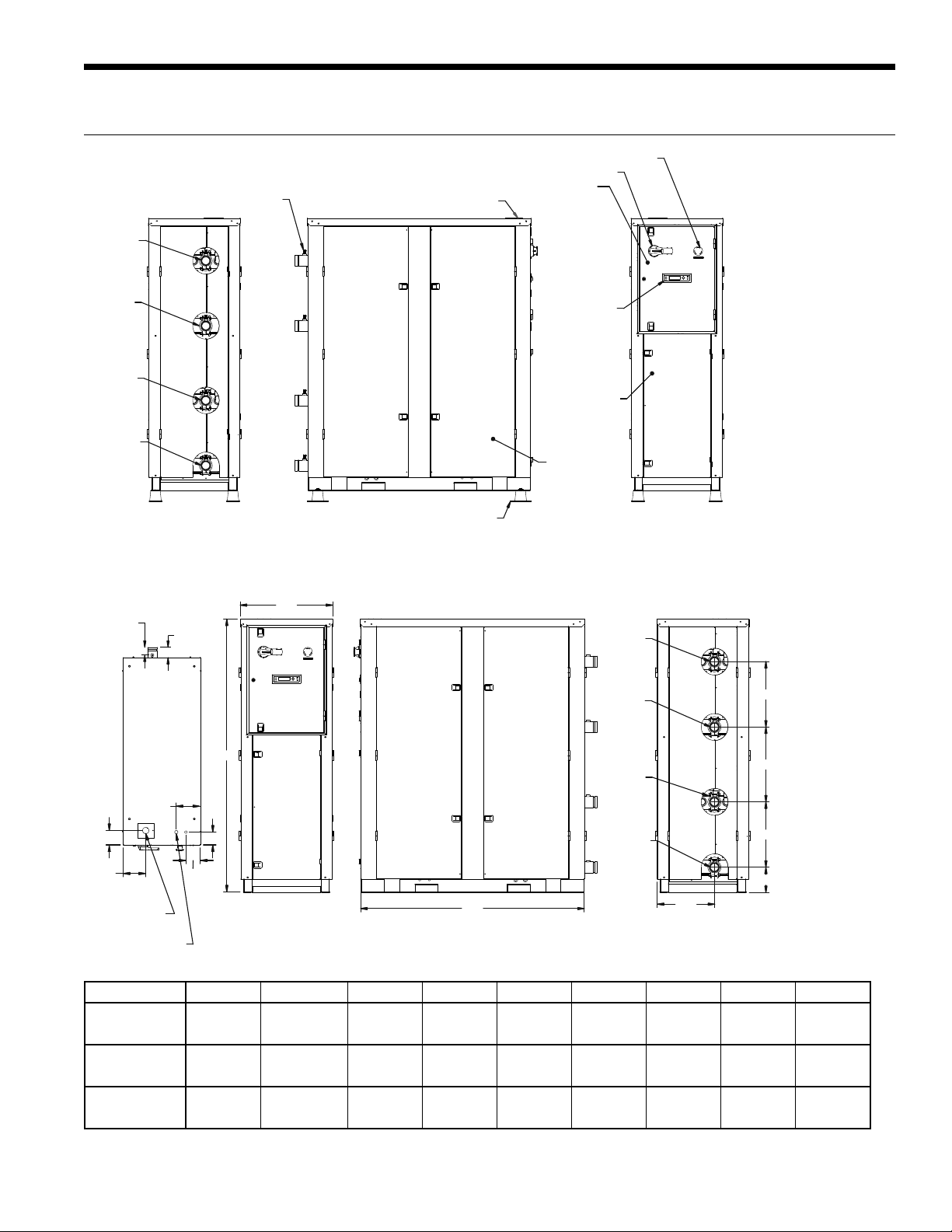
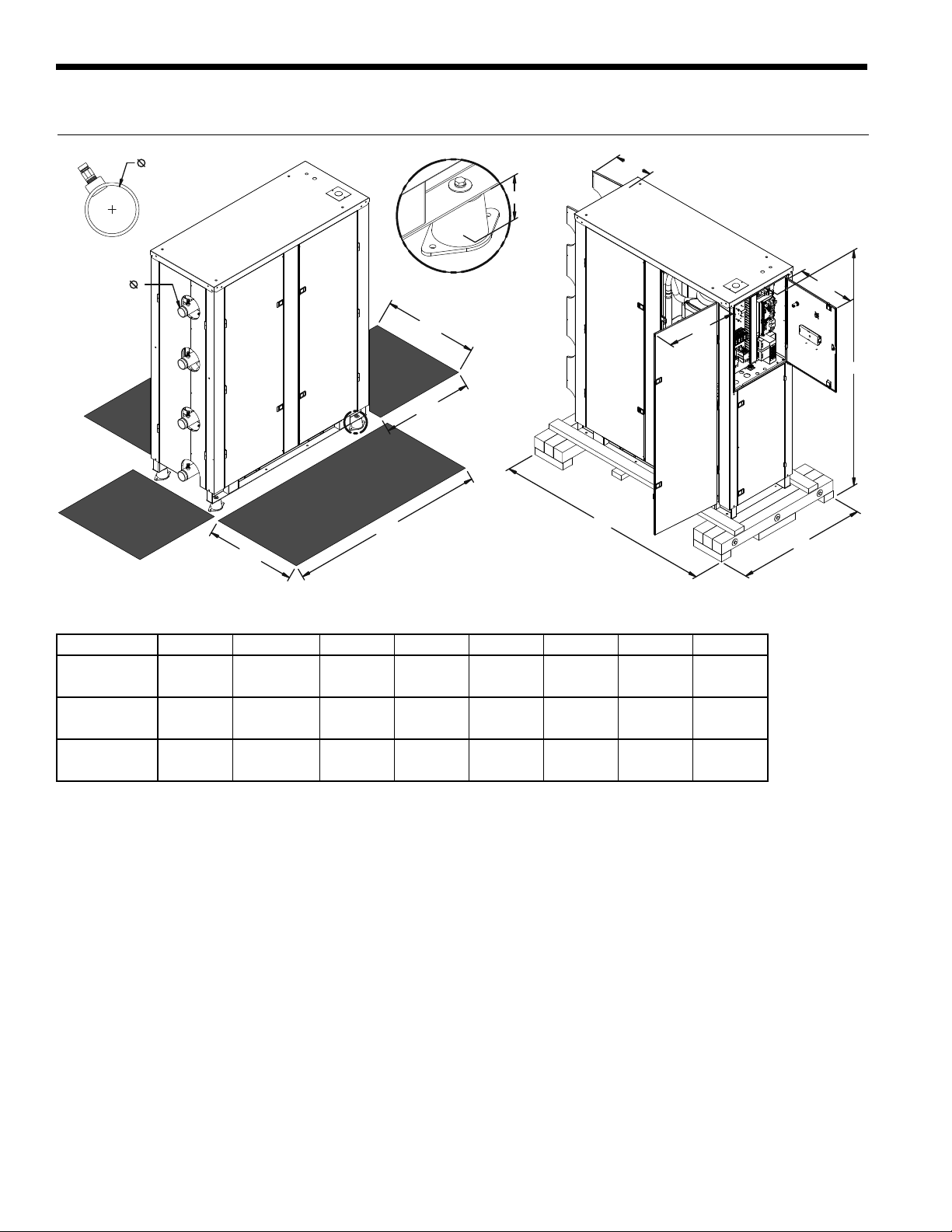
Physical Dimensions
SERVICE PORTS
SOURCE
WATER OUT
ENVISION2 NXW REVERSIBLE CHILLER INSTALLATION MANUAL
EMERGENCY STOP SWITCH
DISCONNECT SWITCH
CONTROL BOX COVER
MAIN POWE R CONNECTION
SOURCE
WATER IN
LOAD
WATER IN
LOAD
WATER OUT
2.40
TO PORT
(SERVICE)
TOP
FX-10
CONTROLLER
DISPLAY
ACCESS DOOR
SIDE ACCESS
PANEL DOORS
VIBRATION PADS
NOTES:
1. DO NOT SCALE DRAWING.
FRONT
"B"
J
SOURCE
WATER OUT
SOURCE
WATER IN
REARSIDE
"G"
7.50
4.50
7.00
ELECTRICAL
HIGH VOLTAGE
ELECTRICAL
LOW VOLTAGE
4.50
4.00
"A"
LOAD
WATER IN
LOAD
WATER OUT
"C"
"H"
"F"
"E"
"D"
Model A B C D E F G H J
120-180
240-360
600
57.3
[1455]
64.2
[1631]
71.1
[1806]
24.1
[612]
24.1
[612]
24.0
[610]
42.5
[1080]
50.5
[1283]
58.5
[1486]
5.0
[127]
6.9
[175]
6.5
[165]
17.0
[432]
17.0
[432]
17.0
[432]
8.8
[224]
13.9
[353]
19.5
[495]
17.0
[432]
17.0
[432]
17.0
[432]
11.9
[302]
12.1
[307]
15.0
[381]
4.6
[117]
3.6
[91]
3.2
[81]
All dimensions in inches, [mm] 5/12/14
7
Page 8
ENVISION2 NXW REVERSIBLE CHILLER INSTALLATION MANUAL
Physical Dimensions, cont.
T
S
T
DETAIL A
25.00
24.00
R
P
N
M
A
52.00
24.00
SHADED AREAS REPRESENT REQUIRED CLEARANCE
FOR SERVICE & MAINTENANCE OF EQUIPMENT.
K
L
Model K L M N P R S T*
120-180
240-360
600
57.0
[1448]
65.0
[1651]
70.0
[1778]
42.0
[1067]
42.0
[1067]
42.0
[1067]
63.1
[1603]
69.9
[1775]
76.8
[1951]
15.9
[404]
19.9
[505]
22.0
[559]
19.5
[495]
19.5
[495]
19.5
[495]
9.7
[246]
9.7
[246]
12.7
[323]
1.3
[33]
1.8
[46]
1.8
[46]
All dimensions in inches, [mm]
*T - Units shipped with groove pipe connection
2.0
[50.8]
2.0
[50.8]
2.5
[63.5]
5/12/14
8
Page 9

Physical Data
ENVISION2 NXW REVERSIBLE CHILLER INSTALLATION MANUAL
Model Compressor
120
180
240
360
600
Weights shown in Pounds, [kg] 1/30/2014
* Refrigerant per circuit in Pounds, [kg]
Add 32 lbs [15 kg] for fluid weight when full. (120)
Add 48 lbs [22 kg] for fluid weight when full. (180)
Add 64 lbs [29 kg] for fluid weight when full. (240)
Add 110 lbs [50 kg] for fluid weight when full. (360)
Add 144 lbs [65 kg] for fluid weight when full. (600)
Scroll (2)
Scroll (2)
Scroll (2)
Scroll (2)
Scroll (2)
Refrigerant
Charge*
5.3 720 710
[2.4] [327] [323]
7.8 838 844
[3.5] [381] [384]
10.5 1130 1152
[4.8] [514] [524]
17.9 1320 1388
[8.1] [600] [631]
27.3 1748 1850
[12.4] [795] [841]
Total Weight
Shipping Installed
NOTE: See page 12 for minimum fluid volume guidelines.
9
Page 10

ENVISION2 NXW REVERSIBLE CHILLER INSTALLATION MANUAL
Field Connected Water Piping
General
System piping should be kept as simple as possible to
minimize the pressure drop, but hand valves should be field
installed to facilitate unit servicing. The piping installation
should provide service personnel with the ability to measure
and/or monitor water temperatures and pressures.
Source and load fluid connections are provided with 2-inch
[50.8mm] Victaulic grooved nipples (see Figure 4). Each
nipple will also have a PT port installed for test and balance
purposes. It will be the installing contractor’s responsibility
to adequately support incoming piping to avoid damage to
the unit’s piping or heat exchangers. The water lines should
be routed so as not to interfere with access to the unit.
For any installation where the transmission of vibration
through the piping connections could cause unacceptable
noise levels in occupied spaces it is important to provide
adequate vibration damping. One method is to use the
optional Adapter Hose Kit (kit number TKC16S-4). This Kit
consists of four pieces of a braided stainless steel flexible
hose with a 2” Victaulic connection on one end and a 2”
MPT connection with pipe union on the other. Overall length
of each piece is 18”.
NOTE: Units are factory run-tested using propylene
glycol. Prior to connecting piping to unit, thoroughly flush
heat exchangers.
NOTE: The placement and connection of the water
circulating pump(s) must be taken into consideration prior
to designing the final water piping systems.
Closed Loop Tower/Boiler Systems
The water loop is usually maintained between 60°F [15.5°C]
and 90°F [32.2°C] for proper heating and cooling operation.
This is accomplished with a cooling tower and a boiler.
To reject excess heat from the condenser water loop, the
use of a closed-circuit evaporative cooler or an open type
cooling tower with a secondary heat exchanger between
the tower and the condenser water loop is recommended.
If an open type cooling tower is used without a secondary
heat exchanger, continuous chemical treatment and filtering
of the water must be performed to ensure the water is free
from damaging materials.
CAUTION: Water piping exposed to outside
temperature may be subject to freezing.
Open Loop Well Water Systems
Installation of an open loop system is not recommended
without using a secondary heat exchanger unless water
quality guidelines are met.
Before final connection to the unit, the supply and return
hose kits must be connected to each other, bypassing
the unit, and the system flushed to remove dirt, piping
chips and other foreign material. Normally, a combination
balancing and close-off (ball) valve is installed at the return,
and a rated gate or ball valve is installed at the supply. The
return valve can be adjusted to obtain the proper water
flow. The valves allow the unit to be removed for servicing.
The proper water flow must be delivered to each unit
whenever the unit heats or cools. The proper flow rate
cannot be accurately set without measuring the water
pressure drop through the refrigerant-to-water heat
exchanger. A 3 GPM flow rate per ton [0.054 LPS per kW]
of cooling capacity (2.25 GPM per ton [0.0404 LPS per
kW] minimum) is required.
CAUTION: Remove the plastic protective caps in the ends of each of the four water pipes on the heat
exchangers prior to piping connection. Failure to remove the caps will result in serious damage and could void
the warranty.
Earth Coupled Systems
All supply and return water piping should be insulated to
prevent excess condensation from forming on the water
lines. Ensure pumping system is capable of providing
adequate flow rate at the system pressure drop, 3.0 GPM
per ton [0.054 LPS per kW] (source side) is recommended.
Antifreeze in the loop is strongly recommended.
10
Page 11
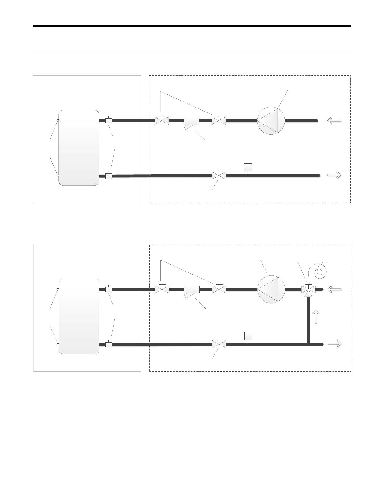
Envision2 NXW Typical Piping
Standard Piping
ENVISION2 NXW REVERSIBLE CHILLER INSTALLATION MANUAL
Field Supplied and InstalledFactory Installed
Pump
Water
Temperature
Sensors
Brazed Plate
Heat Exchanger
1/4” NPT
Pressure/Temperature
Port
Isolation Valves
Strainer
FS
Isolation Valve
Note: System piping should have drain ports to enable flushing and cleaning of heat exchangers. On systems utilizing
pumps with VFDs, an automatic flow control valve must be installed.
Pressure Regulated Piping
Field Supplied and InstalledFactory Installed
Isolation Valves
Pump
Pressure Actuated
Water Valve
From Load
To Load
Compressor
Discharge
Pressure
Strainer
FS
Isolation Valve
Water
Temperature
Sensors
Brazed Plate
Heat Exchanger
1/4” NPT
Pressure/Temperature
Port
Note: System piping should have drain ports to enable flushing and cleaning of heat exchangers. On systems utilizing
pumps with VFDs, an automatic flow control valve must be installed.
From Load
To Load
11
Page 12

ENVISION2 NXW REVERSIBLE CHILLER INSTALLATION MANUAL
Envision2 NXW Application Data
1.0. Minimum Fluid Volume
A. Water-to-water heat pumps require a minimum amount
of source and load side fl uid volume to ensure accurate
and stable temperatures during system operation.
For normal air conditioning type applications, it is
recommended to use at least 7 gallons/ton.
B.
Applications that require more precise temperature
control or low loading will occur the minimum
fl uid volume shall be no less than 10 gallons/ton.
Installation of a buffer tank that will properly mix the
fl uid is recommended.
1.1. Water-to-Water Heat Pump Sizing
A. Heat pumps should be adequately sized for optimal
system effi ciency and run time. Oversizing by more
than 15% can diminish performance resulting in higher
power consumption, short cycling of compressors, and
unstable conditioning temperatures.
B. In applications where the minimum load is signifi cantly
less than the design condition, it is better to install 2
smaller heat pumps for load matching rather than a
single large heat pump.
1.2. Heat Pump Piping
A. Multiple heat pumps can be installed in series or
parallel confi gurations. The preferred system design is
to pipe the equipment in parallel due to its simplicity
and fl exibility. In parallel systems, the heat pump
equipment can vary in size as long as fl ow rate and
system volume are accounted for.
B. Piping equipment in series is not desired; however,
it can be done if proper guidelines are followed.
Always observe proper temperature and fl ow rate
requirements for each unit. Sometimes this method is
desired to achieve larger temperature differences.
1.3. Strainers
A. All brazed-plate heat exchangers shall have a
strainer within 8 ft of the water/brine inlet. It is highly
recommended to use a minimum of 60 mesh in order
to provide maximum fi ltration. In any case, the strainers
should never have a mesh size less than 20.
B. Failure to install proper stainers and perform regular
service can result in serious damage to the unit, and
cause degraded performance, reduced operating life
and failed compressors. Improper installation of the
unit (which includes not having proper strainers to
protect the heat exchangers) can also result in voiding
the warranty.
C. Strainers should be selected on the basis of acceptable
pressure drop, and not on pipe diameter. The strainers
selected should have a pressure drop at the nominal
fl ow rate of the units; low enough to be within the
pumping capacity of the pump being used.
1.4. Flow Sensing Devices
A. A fl ow switch or equivalent must be installed on the
evaporator for each unit to be installed. If the unit is to
operate as both modes (heating/cooling), a fl ow switch
is needed on both heat exchangers.
B. A differential pressure switch can be used in place of a
fl ow switch. The differential switch must be capable of
pressure range as indicated in the pressure drop tables.
1.5. Water Quality
A. General: Reversible chiller systems may be successfully
applied in a wide range of commercial and industrial
applications. It is the responsibility of the system
designer and installing contractor to ensure that
acceptable water quality is present and that all
applicable codes have been met in these installations.
B. Water Treatment: Do not use untreated or improperly
treated water. Equipment damage may occur. The
use of improperly treated or untreated water in this
equipment may result in scaling, erosion, corrosion,
algae or slime. The services of a qualifi ed water
treatment specialist should be engaged to determine
what treatment, if any, is required. The product
warranty specifi cally excludes liability for corrosion,
erosion or deterioration of equipment.
The heat exchangers in the units are 316 stainless steel
plates with copper brazing. The water piping in the
heat exchanger is steel. There may be other materials
in the building’s piping system that the designer may
need to take into consideration when deciding the
parameters of the water quality.
If an antifreeze or water treatment solution is to be
used, the designer should confi rm it does not have a
detrimental effect on the materials in the system.
C. Contaminated Water: In applications where the
water quality cannot be held to prescribed limits, the
use of a secondary or intermediate heat exchanger
is recommended to separate the unit from the
contaminated water.
The following table outlines the water quality
guidelines for unit heat exchangers. If these conditions
are exceeded, a secondary heat exchanger is required.
Failure to supply a secondary heat exchanger where
needed will result in a warranty exclusion for primary
heat exchanger corrosion or failure.
WARNING: Must have intermediate heat exchanger
when used in pool applications.
12
Page 13
ENVISION2 NXW REVERSIBLE CHILLER INSTALLATION MANUAL
Envision2 NXW Application Data cont.
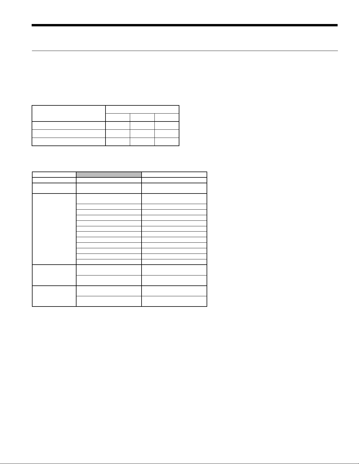
1.6. Insulation
A. Heat pumps are built with factory installed insulation
on any surface that may be subject to temperatures
below the room dew point.
Surface Condensation Chart
Room Ambient Condition
Normal (Max 85°F, 70% RH) 1/2" 3/4" 1"
Mild (Max 80°F, 50% RH) 1/8" 1/4" 1/2"
Severe (Max 90°F, 80% RH) 3/4" 1" 2"
Surface Temperature
50°F 35°F 0°F
Water Quality Guidelines
Material 316 Stainless Steel
pH Acidity/Alkalinity
Scaling
Corrosion
Iron Fouling
(Biological Growth)
Erosion
NOTES: Grains = ppm divided by 17
mg/L is equivalent to ppm
Calcium and
Magnesium Carbonate
Hydrogen Sulfide Less than 1 ppm
Sulfates Less than 200 ppm
Chlorine Less than 0.5 ppm
Chlorides Less than 300 ppm
Carbon Dioxide 10 - 50 ppm
Ammonia Less than 20 ppm
Ammonia Chloride Less than 0.5 ppm
Ammonia Nitrate Less than 0.5 ppm
Ammonia Hydroxide Less than 0.5 ppm
Ammonia Sulfate Less than 0.5 ppm
Total Dissolved Solids (TDS) 1000 - 1500 ppm
LSI Index +0.5 to -0.5
2
Iron, FE
Bacterial Iron Potential
+ (Ferrous)
Iron Oxide
Suspended Solids
Threshold Velocity
(Fresh Water)
(Total Hardness)
less than 350 ppm
< 0.2 ppm
Less than 1 ppm, above this
level deposition will occur
Less than 10 ppm and filtered
for max. of 600 micron size
< 6 ft/sec
7 - 9
1.7. Brine Applications
A. Applications where the leaving fl uid temperature goes
below 40°F a suitable brine solution must be used.
Failure to do so can cause immediate damage to the
system. The brine must be approved for use with heat
exchangers. Automotive antifreeze solutions are not
suitable for use in brazed plate heat exchangers.
B.
The freeze detection must be adjusted appropriately
for brine applications. The brine solution
concentration should be at least 15°F below the
lowest leaving fl uid temperature.
2/22/12
13
Page 14
ENVISION2 NXW REVERSIBLE CHILLER INSTALLATION MANUAL
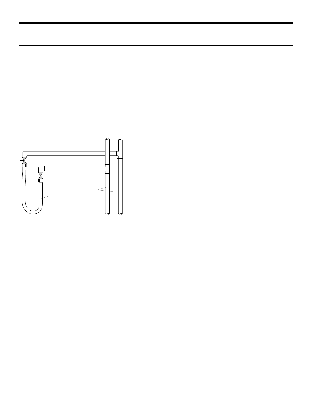
System Cleaning and Flushing
Cleaning and Flushing
Prior to start up of any heat pump, the water circulating
system must be cleaned and flushed of all dirt and debris.
If the system is equipped with water shutoff valves, the
supply and return runouts must be connected together
at each unit location (This will prevent the introduction of
dirt into the unit, see Flushing with Water Shutoff Valve
Equipped Systems illustration). The system should be filled
at the water make-up connection with all air vents open.
After filling, vents should be closed.
Flushing with Water Shutoff Valve Equipped Systems
Return Runout
Supply Runout
Mains
Rubber Hose
Runouts Initially
Connected Together
The contractor should start the main circulator with the
pressure reducing valve makeup open. Vents should be
checked in sequence to bleed off any trapped air and to
verify circulation through all components of the system.
As water circulates through the system, the contractor
should check and repair any leaks found in the piping
system. Drain(s) at the lowest point(s) in the system should
be opened for initial flush and blowdown, making sure
water fill valves are set at the same rate. Check the pressure
gauge at the pump suction and manually adjust the makeup water valve to hold the same positive pressure both
before and after opening the drain valves. Flushing should
continue for at least two hours, or longer if required, until
drain water is clean and clear.
The supplemental heater and/or circulator pump, if used,
should be shut off. All drains and vents should be opened
to completely drain the system. Short-circuited supply and
return runouts should now be connected to the unit supply
and return connections.
Refill the system with clean water. Test the system water
for acidity and treat as required to leave the water slightly
alkaline (pH 7.5 to 8.5). The specified percentage of
antifreeze may also be added at this time. Use commercial
grade antifreeze designed for HVAC systems only.
Environol™ brand antifreeze is recommended.
Once the system has been filled with clean water and
antifreeze (if used), precautions should be taken to protect
the system from dirty water conditions. Dirty water will
result in system-wide degradation of performance, and
solids may clog valves, strainers, flow regulators, etc.
Additionally, the heat exchanger may become clogged
which reduces compressor service life and can cause
premature unit failure.
In boiler/tower application, set the loop control panel
set points to desired temperatures. Supply power to all
motors and start the circulating pumps. After full flow has
been established through all components including the
heat rejector (regardless of season), air vented and loop
temperatures stabilized, each of the units will be ready for
check, test and start up and for air and water balancing.
Ground Source Loop System Checkout
Once piping is completed between the unit pumping
system and ground loop, final purging and charging of
the loop is needed. A high pressure pump is needed to
achieve adequate flow velocity in the loop to purge air
and dirt particles from the loop itself. Antifreeze solution
is used in most areas to prevent freezing. Flush the
system adequately to remove as much air as possible;
then pressurize the loop to a static pressure of 40-50
PSI (summer) or 50-75 PSI (winter). This is normally
adequate for good system operation. Loop static pressure
may decrease soon after initial installation, due to pipe
expansion and loop temperature change. Running the
unit for at least 30 minutes after the system has been
completely purged of air will allow for the “break-in”
period. It may be necessary to adjust static loop pressure
(by adding water) after the unit has run for the first time.
Loop static pressure will also fluctuate with the seasons.
Pressures will be higher in the winter months than during
the cooling season. This fluctuation is normal and should be
considered when charging the system initially.
14
Page 15

Electrical Data
ENVISION2 NXW REVERSIBLE CHILLER INSTALLATION MANUAL
Model
120
180
240
360
600
HACR circuit breaker in USA only
1
- MCC, RLA, & LRA rating per compressor. Breaker & FLA sized for both compressors.
2
- Equipment supplied with Class J fuses per minimum fuse size.
Rated
Voltage
208-230/60/3 187/253 36.0 23.1 160.0 46.2 52.0 60.0 70
460/60/3 414/506 19.0 12.2 87.0 24.4 27.5 30.0 35
575/60/3 517/633 13.5 8.7 62.0 17.4 19.6 20.0 25
380/60/3 342/418 19.0 12.2 95.0 24.4 27.5 30.0 35
208-230/60/3 187/253 45.0 28.8 235.0 57.6 64.8 70.0 90
460/60/3 414/506 19.0 12.2 110.0 24.4 27.5 30.0 35
575/60/3 517/633 16.5 10.9 95.0 21.8 24.5 25.0 35
208-230/60/3 187/253 52.2 35.2 250.0 70.4 79.2 80.0 110
460/60/3 414/506 27.0 19.2 140.0 38.4 43.2 45.0 60
575/60/3 517/633 19.1 14.5 100.0 29.0 32.6 35.0 45
208-230/60/3 187/253 75.0 48.1 351.0 96.2 108.2 110.0 150
460/60/3 414/506 38.6 24.7 197.0 49.4 55.6 60.0 80
575/60/3 517/633 35.0 22.4 135.0 44.8 50.4 60.0 70
380/60/3 342/418 51.0 32.7 239.0 65.4 73.6 80.0 100
460/60/3 414/506 62.0 39.7 260.0 79.4 89.3 100.0 125
575/60/3 517/633 45.0 28.8 210.0 57.6 64.8 70.0 90
380/60/3 342/418 72.0 46.2 310.0 92.4 104.0 110.0 150
Voltage
Min/Max
Compressor
MCC RLA LRA
1
Total
Unit
FLA
Min
Circ
Amp
Min
Fuse/
HACR
Max
Fuse/
HACR
2
3/5/14
Compressor Protection Module
An electronic protection module is provided with
compressors utilized in model size 600. This module will
protect against phase reversal and phase loss at start-up.
Protection is active for 5 seconds after the first second
of compressor operation. In the event that either phase
sequencing or phase loss has occurred the following
blink sequence will display on the module.
15
Page 16

ENVISION2 NXW REVERSIBLE CHILLER INSTALLATION MANUAL
Electrical Data cont.
Figure 6: Control Box
Power Supply
(Field line voltage
connection)
Fused /
Non-Fused
Disconnect
Class J Fuses
Transformer
Class CC Fusing
for Transformer
FX10 Control
Board
FX10 Expansion
Board
Compressor
Contactor (Lower)
Compressor
Contactor (Upper)
Compressor
Current Sensors
Field Low Voltage
Connections
16
Page 17

Wiring Schematics
ENVISION2 NXW REVERSIBLE CHILLER INSTALLATION MANUAL
Chiller with IntelliStart
11/14/13
97P862-01
Yellow (17)
Black/White (18)
Yellow (19)
Black/White (20)
Red
Grn/Yel
Blue
Red
Compressor
Unit Power Supply
L1 L2 L3
Disconnect(fused disconnectoptional)
LP – Low Pressure
Legend
CC – Compressor Contactor
Black
F10
Black (97)
L
Protection
Compressor
T3
T2S2S1
Earth Ground
Grn/Yel
Blue
(Circuit 2)
Compressor
L
N
(CPM1)
Protection
Module#1
Compressor
T1
T3
T2S2S1
Black
Earth Ground
(Circuit 1)
Disconnecthandle
F3
F2
F1
G
PB – Power Block
RV – Reversing Valve
SFS – Source Flow Switch
PGM – Phase Guard Monitor
LST – Leaving Source Temp
L-WCT – Load Water Coil Temp
ressor Protection Module
EST – Entering Source Temp
HP – High Pressure
CPM – Comp
CS – Current Switch
ELT – Entering Load Temp
ES – Emergency Shutdown
PB1
Yellow
Black/White
24V
Transformer
Red for 208V
Blue for 230-240V
F11
Blue (98)
N
NOTE 10
(CPM2)
Module#2
T1
Blue
Blue
Black
Black
S1
S2
T1
T2
T3
Red
NOTE 10
Blue
Black
Blue
White
S1
S2
T1
T2
T3
Red
Current Switch
Red(C)
(throughthe door)
L2L1 L3
Black(G)
Closed Jumper
Open Jumper
S-WCT – Source Water Coil Temp
F - Fuse
TB – Terminal Board
Field low voltage wiring
Field line voltage wiring
Factory low voltage wiring
Optional block
Factory line voltage wiring
S - Splice
LFS – Load Flow Switch
LLT – Leaving Load Temp
Black (95)
231
Green/Yellow (16)
Red for 380V
Blue for 460V
Blue for 575V
L2(IN)
L2(OUT)
L1(IN)
L1(OUT)
L3
Black(Q)
White
White(R)
T1T2T3
Black
CC2
Black
Black
Current Switch
CS2
L2(IN)
L2(OUT)
L1(IN)
L1(OUT)
L3
Black(N)
White(P)
T1T2T3
White(B)
White(H)
L1L2L3
CC1
Black
Black
CS1
F5 F6
L1 L2 L3
F4
Black(A)
Red(J)
L1 L2 L3
F7 F8 F9
Black
Ground
¼” Quick Connector
Relay coil
Field Supplied Option
Thermistor
T
(22)
Black/White
(62)
Black/White
(21)
Yellow
Soft
Start
L1L2L3
Soft
Start
Red (F)
White (E)
Black(D)
L2L1 L3
L2L1 L3
TB
24VAC COM
DO-9
24VACSSDO-8
RS
R
C
Black (R)
Black (C)
Black (RS)
Black (SS)
B
1
15
14613
Black (30)
Black (29)
Black/White (26)
(26)
Black/White
Yellow (24)
A
20
Black (F20)
20
Green/Yellow (23)
J8
White/Red (81)
White/Red (80)
White/Blue (33)
L-WCT
S-WCT
Circuit 1
Black (30)
19
Black (F19)
19
D09
GROUND
24VAC Com
24VAC
AI3
-
5VDC
White/Red (80)
1019202122
White/Blue (34)
Yellow/Red (35)
S-WCT
Circuit 1
Black (29)
18
Black (F18)
AI5
-
+
White/Red (81)
White/Blue (33)
Yellow/Red (36)
Yellow/Blue (37)
TTT
L-WCT
Circuit 2
S2
18
D08
NOTE 6
+
White/Blue (34)
Yellow/Blue (38)
T
Circuit 2
(24)
Yellow
Orange (61A)
Orange (61B)
Yellow (21)
Blue (98)
Black (97)
Black/White (22)
Red (M)
White (L)
Black(K)
Orange (61A)
Orange (61B)
Orange (60)
S1
21789
14
13
Orange (60A)
Orange (61A)
Orange/Wht (60B)
Orange/Wht (61B)
RV2
RV1
NOTE 7
DO-7
X2
Black (X2)
Yellow (25)
Yellow
17
Black (F17)
17
-
AI4
+
Yellow/Red (35)
Yellow/Red (36)
353132
34
Tan/Black (85)
Tan/Black (84)
T
LLT
Comp B
Alarm
LC2
Black (LC2)
11
Black (28)
Brown (53)
Black (28)
Brown (53)
161514
Black (F16)
15
16
D07
A34
A24
A14
-
-
+
AI6
Tan/Black (84)
Yellow/Blue (37)
Yellow/Blue (38)
4
Blue (76A)
Tan/White (83)
Tan/White (82)
LP-1
T
ELT
Comp A
Alarm
LC1
Black (LC1)
Black (F15)
AI2
+
3332313029282726252423
Tan/Black (85)
3
Blue (49A)
NOTE 3
Acc
X1
Black (X1)
3
Brown (52)
Brown (52)
Yellow
Black (F14)
14
A33
A35
A25
-
5VDC
353637
34
Tan/White (82)
Black (49)
S6
16
15
Blue/Wht (49B)
Blue/Wht (76B)
LP-2
5
Blue (51)
Blue (51)
AI1
+
5
Black (73A)
HP-1
COMP 1
Y1
Black (Y1)
10
Blue (45)
Black/White (62)
13
Black (F13)
13
6
D0
A31
A32
A22
A21A12
LED
Tan/White (83)
6
1718292826
Black (74A)
Black/Org (73B)
HP-2
COMP 2
Y2
Black (Y2)
Blue (46)
12
Black (F12)
12
A11
A13
A23
5VDC
38
Brn/Blk (42)
Black/Org (74B)
T
LST
Yellow
J2
Brn/Blk (41)
REV VALVE
O/B
Black (O/B)
Orange (47)
Black (F11)
PWM2
PWM2 Com
39
25
Brn/Wht (87)
Brn/Wht (86)
T
EST
NOT USED
NOT USED
NOT USED
NOT USED
NOT USED
G
Black (G)
294
10611
Black (F10)
11
10
D05
D04
PWM1
41
40
AIC
9
A15
Brn/Blk (41)
Brn/Blk (42)
Black (AIC)
7
Black (F9)
9
24VAC Com
J10
42
Brn/Wht (87)
Black (75A)
TO
SC
L
Black (L)
Black (SC)
8
12
Black/Org (75B)
S3
Black
Orange (60)
7
8
Black (F7)
Black (F8)
765
8
D03
Johnson FX-10
DI12
DI11
DI10
DI9
DI8
444546
47
43
Blue (46)
Gray (48)
White (88)
White (89)
Orange (47)
SFS
NOTE 5
Connect to R on TB
CS-B
Circuit B
CS-A
Circuit A
Brn/Wht (86)
Black (TO)
16
White (89)
Black (F6)
DI7
48
Blue (45)
D02
Black
Black
Black
Black
Notes
1 - Disconnect for 15 degree source side freeze protection
2 - Disconnect for 15 degree load side freeze protection
Black/White (63)
CC2
CC1
(72B)
Black/Org
Black (72A)
M2M1
M2M1
CPM1
CPM2
NOTE 9
Black
(71A)
(71B)
Black/Org
Black/Org (70B)
Black (70A)
Violet (67)
Violet (66)
2
3
4
5
Black (F2)
Black (F4)
Black (F3)
Black (F5)
3
4
2
D01
DI 3/4/5/6/ Com
DI6
DI5
DI4
DI3
DI2
J9
52
50
51
49
53
54
Black
Red (55)
Gray (56)
Blue (76A)
Blue (76B)
Brown (57)
S5
NOTE 8
NOTE 1
NOTE 2
Black (54)
PB2
1
White (B)
White (B)
J2
31
30
29
Black (A)
Black (A)
28
27
26
25
24
23
22
21
20
J3
17
16
15
14
13
12
11
10
be removed to check the jumpers.
PB2-3 for the unit to operate.
5 – A field installed flow switch is required for the source side and must be connected
to R for the unit to operate.
3 – Acc output is cycled with the lead compressor.
4 - A field installed flow switch is required for the load side and must be connected to
NOTE 9
White (88)
1
Black (F1)
1
DI1
9VDC
55
56
Pink (58)
Gray (59)
ES
Brown (99)
3
2
5Vdc Com
AI4 EXP
c
5Vd
5Vdc Com
AI3 EXP
c
5Vd
5Vdc Com
AI2 EXP
c
5Vd
5Vdc Com
AI1 EXP
c
5Vd
DO3
24 Vac
DO4
DO5
24 Vac
DO6
24 Vac Com
24 Vac
8 – In Emergency Shutdown, line voltage is still present in control box. Emergency
7 – Reversing Valve will be energized for heating mode.
6 - Jumpers must be set as shown for correct control operation. If a communication
card is present, it must
White (89)
Black/Org (70B)
Black (70A)
White (88)
J7
NOTE 4
LFS
White (88)
White (89)
Black (70A)
Black/Org (70B)
Connection
J1
Main Board
A43
A41
A42
A31
A32
A33
A21A22
A23
A13
A12
A11
Johnson FX10
Expansion Board
Page 1
inside of the compressor junction boxes. Only used on the 600 model.
9 – M1 and M2 are located on the compressor protection modules (CPM1 and CPM2)
Switch is wired on low voltage circuit only.
10 – Only used on the 600 model.
Orange (47)
Blue (46)
Blue (45)
Black (75A)
Black/Org (75B)
Orange (60)
BLACK WIRE HARNESS
Black/Org (75B)
Black (75A)
Blue (45)
Orange (60)
Blue (46)
Orange (47)
8
D08
7
6
D07
5
4
D02
3
2
1
D01
NOTE 7
17
Page 18

ENVISION2 NXW REVERSIBLE CHILLER INSTALLATION MANUAL
Wiring Schematics cont.
Chiller with Phase Guard
11/14/13
97P862-02
Y-OUT
PGM
Y
Yellow (17)
Black/White (18)
Yellow (19)
Black/White (20)
Red
Grn/Yel
Blue
Red
Compressor
Unit Power Supply
L1 L2 L3
Disconnect(fused disconnectoptional)
LP – Low Pressure
Legend
CC – Compressor Contactor
C
Yellow (100)
Yellow
24V
Black
F10
Black (97)
L
Protection
Module#2
Compressor
T3
T2S2S1
Earth Ground
Grn/Yel
Blue
(Circuit 2)
Compressor
L
N
(CPM1)
Protection
Module#1
Compressor
T1
T3
T2S2S1
Black
Earth Ground
(Circuit 1)
Disconnecthandle
F3
F2
F1
G
PB – Power Block
RV – Reversing Valve
SFS – Source Flow Switch
S-WCT – Source Water Coil Temp
PGM – Phase Guard Monitor
LST – Leaving Source Temp
L-WCT – Load Water Coil Temp
ressor Protection Module
Y
EST – Entering Source Temp
HP – High Pressure
LFS – Load Flow Switch
CPM – Comp
CS – Current Switch
ELT – Entering Load Temp
ES – Emergency Shutdown
Yellow (80)
PB1
Black/White
Transformer
Red for 208V
Red for 380V
Blue for 230-240V
F11
Blue (98)
N
NOTE 10
(CPM2)
T1
Blue
Blue
Black
S1
S2
T1
T2
T3
Red
NOTE 10
Blue
Blue
S1
S2
T1
T2
T3
Red
Current Switch
Red(C)
(throughthe door)
White(B)
L2L1 L3
White(H)
Black(G)
Open Jumper
F - Fuse
TB – Terminal Board
Field low voltage wiring
Factory low voltage wiring
Factory line voltage wiring
LLT – Leaving Load Temp
S - Splice
Black (95)
231
Green/Yellow (16)
Blue for 460V
Blue for 575V
L3L2L1
Phase
Guard
Monitor
(PGM)
Black
White
Black
Black
Current Switch
CS2
Black
T1T2T3
CC1
White
Black
Black
CS1
F5 F6
L1 L2 L3
F4
Black(A)
Red(J)
L1 L2 L3
F7 F8 F9
Ground
Closed Jumper
¼” Quick Connector
Relay coil
Field line voltage wiring
Field Supplied Option
Optional block
Thermistor
T
Black/White
(62)
Black/White
Yellow
Black/White (27)
White (8)
Black(7)
T1T2T3
L1L2L3
CC2
L1L2L3
Red (F)
White (E)
L2L1 L3
L2L1 L3
(22)
(21)
Black(D)
TB
24VAC COM
DO-9
24VACSSDO-8
RS
R
C
Black (R)
Black (C)
Black (RS)
Black (SS)
B
1
15
14613
Black (30)
Black (29)
Yellow (25)
Black/White (26)
(26)
Black/White
Yellow (24)
A
20
Black (F20)
20
Green/Yellow (23)
J8
White/Red (81)
White/Red (80)
S-WCT
Circuit 1
Black (30)
19
Black (F19)
19
D09
GROUND
24VAC Com
24VAC
-
5VDC
White/Red (80)
1019202122
White/Blue (34)
White/Blue (33)
L-WCT
Circuit 1
Black (29)
18
Black (F18)
AI3
-
+
White/Red (81)
White/Blue (33)
Yellow/Red (35)
Yellow/Red (36)
Yellow/Blue (37)
TTT
L-WCT
S-WCT
Circuit 2
S2
18
D08
NOTE 6
AI5
+
White/Blue (34)
Yellow/Blue (38)
T
Circuit 2
-
(24)
Yellow
Orange (61A)
Orange (61B)
Yellow (21)
Blue (98)
Black (97)
Black/White (22)
Red (9)
Red (M)
White (L)
Black(K)
Orange (61A)
Orange (61B)
Orange (60)
S1
21789
14
13
Orange (60A)
Orange (61A)
Orange/Wht (60B)
Orange/Wht (61B)
RV2
RV1
NOTE 7
DO-7
X2
Black (X2)
Yellow
17
Black (F17)
17
AI4
+
Yellow/Red (35)
Yellow/Red (36)
353132
34
Tan/Black (85)
Tan/Black (84)
T
LLT
Comp A
Comp B
Alarm
LC2
Black (LC2)
11
Black (28)
Brown (53)
Black (28)
Brown (53)
161514
Black (F16)
Black (F15)
15
16
D07
A34
A24
A14
-
-
AI2
+
AI6
Tan/Black (84)
Yellow/Blue (37)
Yellow/Blue (38)
4
3
Blue (49A)
Blue (76A)
Tan/White (83)
Tan/White (82)
LP-1
T
ELT
Alarm
LC1
Black (LC1)
3
Brown (52)
Brown (52)
Yellow
A33
A35
A25
+
5VDC
34
3332313029282726252423
Tan/Black (85)
Black (49)
S6
16
15
Blue/Wht (49B)
Blue/Wht (76B)
LP-2
NOTE 3
Acc
X1
Black (X1)
5
Black (F14)
14
AI1
-
353637
Tan/White (82)
5
Black (73A)
Blue (51)
Black/White (62)
Blue (51)
13
Black (F13)
D0
A31
A32
A22
A21A12
+
Tan/White (83)
6
Black (74A)
HP-1
COMP 1
Y1
Black (Y1)
13
LED
COMP 2
Y2
Black (Y2)
10
Blue (45)
Blue (46)
12
Black (F12)
12
6
5VDC
38
1718292826
Brn/Blk (42)
Black/Org (73B)
Black/Org (74B)
HP-2
LST
A11
A13
A23
Brn/Blk (41)
T
Black (O/B)
Yellow
J2
REV VALVE
O/B
Orange (47)
Black (F11)
PWM2
39
25
Brn/Wht (87)
Brn/Wht (86)
T
EST
11
D05
PWM2 Com
40
NOT USED
G
Black (G)
294
10611
Black (F10)
10
D04
PWM1
41
NOT USED
AIC
A15
Brn/Blk (42)
Black (AIC)
7
9
Black (F9)
9
24VAC Com
J10
42
Brn/Wht (87)
Brn/Blk (41)
NOT USED
NOT USED
L
SC
Black (L)
Black (SC)
8
12
Black (75A)
Black/Org (75B)
S3
Black
Orange (60)
7
8
Black (F8)
Black (F7)
765
8
D03
Johnson FX-10
DI12
DI11
DI10
444546
43
Gray (48)
White (88)
White (89)
SFS
NOTE 5
Connect to R on TB
CS-B
Circuit B
CS-A
Circuit A
Brn/Wht (86)
NOT USED
DI9
Orange (47)
TO
Black (TO)
16
DI8
47
Blue (46)
White (89)
Black (F6)
DI7
48
Blue (45)
D02
Black
Black
Black
Black
Notes
1 - Disconnect for 15 degree source side freeze protection
2 - Disconnect for 15 degree load side freeze protection
Black/White (63)
CC2
CC1
(72B)
Black/Org
Black (72A)
M2M1
M2M1
CPM1
CPM2
NOTE 9
Black
(71A)
(71B)
Black/Org
Black/Org (70B)
Black (70A)
Violet (67)
Violet (66)
2
3
4
5
Black (F3)
Black (F2)
Black (F4)
Black (F5)
3
4
2
D01
DI 3/4/5/6/ Com
DI6
DI5
DI4
DI3
DI2
J9
52
50
51
49
53
54
Black
Red (55)
Gray (56)
Blue (76A)
Blue (76B)
Brown (57)
S5
NOTE 8
NOTE 1
NOTE 2
Black (54)
PB2
1
White (B)
White (B)
J2
31
30
29
Black (A)
Black (A)
28
27
26
25
24
23
22
21
20
J3
17
16
15
14
13
12
11
10
Page 1
be removed to check the jumpers.
inside of the compressor junction boxes. Only used on the 600 model.
PB2-3 for the unit to operate.
5 – A field installed flow switch is required for the source side and must be connected
3 – Acc output is cycled with the lead compressor.
4 - A field installed flow switch is required for the load side and must be connected to
NOTE 9
White (88)
1
Black (F1)
1
J7
DI1
9VDC
55
56
Pink (58)
Gray (59)
ES
NOTE 4
LFS
Brown (99)
3
2
5Vdc Com
AI4 EXP
c
5Vd
A43
5Vdc Com
AI3 EXP
c
A42
5Vd
5Vdc Com
A32
AI2 EXP
c
A33
5Vd
5Vdc Com
AI1 EXP
A21A22
c
5Vd
A12
A11
DO3
24 Vac
DO4
DO5
24 Vac
DO6
24 Vac Com
24 Vac
9 – M1 and M2 are located on the compressor protection modules (CPM1 and CPM2)
to R for the unit to operate.
8 – In Emergency Shutdown, line voltage is still present in control box. Emergency
Switch is wired on low voltage circuit only.
7 – Reversing Valve will be energized for heating mode.
6 - Jumpers must be set as shown for correct control operation. If a communication
card is present, it must
10 – Only used on the 600 model.
Orange (47)
Blue (46)
Blue (45)
Black (75A)
Black/Org (75B)
Orange (60)
White (89)
Black/Org (70B)
Black (70A)
White (88)
BLACK WIRE HARNESS
White (88)
White (89)
Black/Org (75B)
Black (70A)
Black/Org (70B)
Black (75A)
Blue (45)
Orange (60)
Blue (46)
Orange (47)
Connection
J1
Main Board
Expansion Board
8
D08
7
6
D07
5
4
D02
3
2
1
D01
A41
A31
A23
A13
Johnson FX10
NOTE 7
18
Page 19

Field Wiring and Control Setup
ENVISION2 NXW REVERSIBLE CHILLER INSTALLATION MANUAL
High Voltage Connections
Unit Power Supply
208-230/60/3,
460/60/3, or 575/60/3
L3L1L2
G
PB
Black
Black
Red
Red
White
White
Low Voltage Connections
TB Typical AquaStat
24VAC
R
24V COM
Rev Valve
Circuit 1 Alarm
Circuit 2 Alarm
NOTES:
1) Acc Output 1 is cycled with the lead compressor
2) Acc Output 2 is cycled with the lag compressor
Comp 1
Comp 2
Acc 2
Acc 1
Alarm
C
Y1
Y2
O/B
X2
X1
L
LC1
LC2
Wiring Schematic
SFS
NOTE 5
24VAC
R
24V COM
C
Comp 1
Y1
Comp 2
Y2
Rev Valve
B
Accessory Item 1
Orange ( 47)
White (66)
White (67)
Gray (48)Connect to R on TB
Blue (46)
Blue (45)
Line Voltage
Power supply wiring connects directly to lugs on the topo
of the electrical disconnect. In 208-230V applications, heat
pumps are factory wired for 208V supply. In the case of
230V supply, the blue and red wires from the primary of the
transformer will need to be swapped.
Low Voltage Operation
Thermostat/Controller (Aquastat)
A two-stage 24VAC aquastat or liquid controller (field
supplied) must be used to turn the reversible chiller on/off, and
to switch modes for heating/cooling. Multiple chillers in the
same bank must be controlled from one aquastat/controller
(must be isolation relays for multiple unit applications).
Low Voltage Connections
Connect low voltage wiring as shown in Figure 9.
Connections shown are for typical aquastat. Actual
connections may vary with specific device used.
NOTE: If a separate transformer is used to supply a Y1, Y2, or
B signal to the unit controls, isolation relays must be used.
CAUTION: Use only copper conductors for field
installed wiring. Terminals in the unit are not
designed for other types of conductors.
WARNING: All wiring must comply with local and
state codes. Disconnect the power supply before
beginning to wire to prevent electrical shock or
equipment damage.
NOTE: Accessory 1 output is selectable as on with
compressor or off with compressor using the unit display.
on with compressor is the factory default setting.
J10
24VAC Com
42
DI12
43
DI11
44
DI10
45
DI9
46
DI8
47
DI7
48
Source Flow Switch (SFS)
Unit is factory shipped with no connections on Flow Switch
pins J10-45 (entering). If flow proving switch is required,
hook up as shown in Fig. 10 and Note 5. The unit will not
operate without flow proving inputs open.
PB2
J9
49
50
51
52
53
54
55
56
DI 3/4/5/6/ Com
DI6
DI5
DI4
DI3
DI2
9VDC
DI1
Black (54)
Blue (76A)
1
2
3
NOTE 2
NOTE 1
ES
NOTE 8
LFS
NOTE 4
Red (55)
Gray (56)
Blue (76B)
Brown (57)
Pink (58)
Gray (59)
Load Flow Switch (LFS)
Unit is factory shipped with no connections on Flow Switch
pins J9-56 (leaving). If flow proving switch is required, hook
up as shown in Fig. 10 and Note 4. The unit will not operate
without flow proving inputs open.
ATTENTION: Flow Switch inputs must be
made before unit will operate!
19
Page 20

ENVISION2 NXW REVERSIBLE CHILLER INSTALLATION MANUAL
Field Wiring and Control Setup cont.
Accessory Relay Setup
The accessory output set to “close” upon Y1 compressor call
(compressor is delayed 90 sec. after Y1) but can be set to
“open” with Y1.
To change ACC1:
• Using up and down keys, scroll to “Acc 1 Sel” hit “ENTER”
and “ON Comp” begins flashing
• Using up and down keys, select “ON Comp” for activation
with Y1 Call or “OFF Comp” for deactivation with Y1
Lead/Lag Selection
Compressor Lead/Lag Selection is factory set to “ON” but
can be set to “OFF”.
To change Lead/Lag On/Off:
• Using up and down keys, scroll to “LEAD/LAG SELECT”
hit “ENTER” and “ON” begins flashing
• Using up and down keys, select “ON” for activation or “
OFF” for deactivation
Control Features
Anti Short Cycle
High Pressure Protection
Low Pressure Protection
Advanced Freeze Detection Setpoint
Random Start
Display for diagnostics
Reset Lockout at disconnect
Intelligent reset for field installed flow switches
1 Accessory output
Compressor Lead/Lag
Compressor Current Switches
°F or °C - Unit of Measure
Degrees Fahrenheit is factory set, however degrees Celsius
can be selected using the following procedure:
To Change Unit of Measure:
• On FX10 control using up and down keys, scroll to
“SETTINGS”
• Using up and down keys, scroll to “UNIT OF MEASURE”
hit “ENTER” and “UNIT OF MEASURE” begins flashing
• Using up and down keys, select “F” for degrees
Fahrenheit or “C” for degrees Celsius
Other Field Options
Other field selectable options are available as shown in the
maintenance menu on page 24 of the FX10 control using a
similar procedure as shown in the above examples. These
would include aquastat enabling, and emergency shutdown.
Control and Safety Features
Emergency Shutdown
The emergency shutdown mode can be activated by a
command from a facility management system or a closed
contact on DI-2. The default state for the emergency
shutdown data point is off. When the emergency shutdown
mode is activated, all outputs will be turned off immediately
and will remain off until the emergency shutdown mode is
deactivated. The first time the compressor starts after the
emergency shutdown mode has been deactivated, there will
be a random start delay present.
Field Selectable Options
Freeze Detection Sensing Select (DI-4 and DI-5)
The freeze detection temperature sensing selection inputs
allow the user to adjust the setpoints. The source sensors
are wired to inputs AI-3 and AI-4 while the load sensors are
wired to inputs AI-5 and AI-6. The setpoints for both, the
load and source, are factory set for 33°F. In order to change
the setpoint to 15°F on the source, remove the jumper wire
from DI-4 (wire #56). The load setpoint can be changed by
removing the jumper wire from DI-5 (wire #55).
Accessory Output (DO-4)
The accessory output will be energized 90 seconds prior to
the lead compressor output being energized. When the lead
compressor output is turned off the accessory output will be
deactivated after 90 seconds. The output is selectable for on
with compressor or off with compressor operation through
the unit mounted user interface.
Lockout Mode
Lockout mode can be activated by any of the following
fault signals: refrigerant system high pressure, refrigerant
system low pressure, heating freeze detection, cooling
freeze detection, and compressor current sensor.
any valid fault signal remains continuously active for the
length of its recognition delay, the controller will go into fault
retry mode, which will turn off both compressors. After the
compressor short cycle delay, the compressors will attempt
to operate once again. If three consecutive faults occur in 60
minutes, the unit will go into lockout mode, turning off the
compressor(s), enabling the alarm output until the controller
is reset. If the control faults due to the low pressure input
being open during the pre-compressor startup check, the
control will go into lockout mode immediately, disabling the
compressors from starting and enabling the alarm output.
The lockout condition can be reset by powering down the
controller, by a command from the BAS, or by the holding
the ESC and Return keys on the user interface for 5 seconds.
20
When
Page 21

Control Features
ENVISION2 NXW REVERSIBLE CHILLER INSTALLATION MANUAL
Advanced Freeze Detection System
The source and load heat exchangers are protected by a
multi-sourced temperature logic strategy. The temperature
logic is based upon the refrigerant temperature sensed as
the refrigerant is about to enter the heat exchanger; while
entering and leaving water temperatures are being used as
correlating factors. The detection scheme is shown as basic
and advanced algorithms.
Basic Freeze Detection Operation: “Comp1 or
Comp2 Freeze” Alarm
This alarm can be triggered by one of two detection
schemes.
Hard Limit Freeze Detection
If the refrigerant temperature drops below the freeze
detection setpoint by 1.8°F, the associated compressor
is locked out immediately regardless of any other
factors and requires a manual reset. NOTE: This Lockout
produces a “Comp 1 or Comp 2 Freeze” error on the
MUI display.
Freeze Detection
The refrigerant temperature is compared to the freeze
detection setpoint (15°F [antifreeze] or 33°F [water]
field selectable), and if the temperature falls below the
setpoint for 30 continuous seconds, the associated
compressor will be halted. This function becomes
enabled after the first two minutes of compressor
operation. Three such events in 60 minutes will trigger a
compressor lockout that requires a manual reset. NOTE:
This Lockout produces a “Comp 1 or Comp 2 Freeze”
error on the MUI display.
In addition to the above:
Entering Water Temperature Influence
If the entering water temperature of the evaporative
heat exchanger is within 10°F of the freeze setpoint,
the previously mentioned two minute delay will be
eliminated. This allows the freeze detection to operate
immediately when the compressor starts based on
entering water temperature.
Leaving Water Temperature Influence
If the leaving water temperature of the evaporative
heat exchanger is within 10°F of the freeze setpoint, the
previously mentioned 30 second delay will begin to be
proportionately reduced, ending at a 1 second delay
when the leaving water temperature is 1.5°F above the
freeze setpoint.
Dual Circuited Heat Exchanger Protection
A low temperature condition on either refrigerant circuit
will prevent the start of both compressors. If the low
temperature condition exists for 5 minutes when both
compressors are off, a lockout is triggered for both
compressors. However, if –for instance-both compressors
are operating and circuit 1 experiences a refrigerant
temperature below the freeze detection setpoint such
that compressor 1 is halted, compressor 2 will not be
halted as a result.
Advanced Freeze Detection Operation:
“Pre Freeze” Alarm
Predictive freeze condition detection:
If the refrigerant temperature is within 7.2°F of the freeze
detection setpoint, the predictive freeze detection
algorithm is enabled, and if the logic determines that
a freeze condition is likely to happen based on current
conditions, the compressor of the involved refrigerant
circuit is immediately stopped. Three (3) such events
in 60 minutes will trigger a compressor lockout that
requires a manual reset. In the absence of such a
condition, the compressor is allowed to operate so that
the refrigerant temperature may eventually be at the
threshold of the freeze detection setpoint. NOTE: This
Lockout produces a “Pre Freeze” detection error on
the MUI display.
Capacity Limiting
If the leaving water temperature drops to 1.8°F above the
freeze detection setpoint, the lead compressor is halted.
When the leaving water temperature rises to 3.6°F above
the freeze detection setpoint, it will be allowed to resume
operation. This limiting is allowed to repeat indefinitely. This
causes “COMP1 Low Limit” to be displayed on the MUI.
If the leaving water temperature drops to the freeze
detection setpoint, the lag compressor is halted. When the
leaving water temperature rises to 1.8°F above the freeze
detection setpoint, it will be allowed to resume operation.
This limiting is allowed to repeat indefinitely. This causes
“COMP2 Low Limit” to be displayed on the MUI.
Compressor Current Switch (AI-3 EXP and AI-4 EXP)
The compressor current switch is designed to insure that
the compressor is on when the compressor output is
energized. This switch is normally open and closes when
current is flowing to the compressor. If the compressor fails
to start the switch will open. The switch must be open for a
continuous 15 seconds for a fault to occur. After 3 faults in
60 minutes the control will put the unit into an alarm state.
Flow Proving Switch (DI-1 and DI-10)
The load and source flow-proving switches are optional and
can be field installed. These switches shall be normally open
flow switches that will close when the water flow through
the heat exchangers reach an acceptable level. The flowproving switches must be closed 15 seconds prior to enabling
either compressor output (DO-1 and DO-2). If the load flowproving switch opens at any time both compressor outputs
(DO-1 and DO-2) must be disabled immediately.
High Pressure (DI-11 and DI-12)
The high-pressure switches shall be a normally closed (NC)
switch that monitors the systems compressor discharge
refrigerant pressures. There shall be an individual high
pressure switch for each circuit. If the input senses the
high-pressure switch is open during the period that the
compressor output is enabled, it must shut down the
compressor immediately and count the fault. The compressor
21
Page 22

ENVISION2 NXW REVERSIBLE CHILLER INSTALLATION MANUAL
Control Features cont.
minimum on time does not apply if the high-pressure switch
trips. The compressor will not restart until the short cycle
time delay has been satisfied. If the high-pressure fault
occurs in one circuit the other compressor will continue to
operate based on the heating or cooling demand.
Low Pressure (DI-3 and DI-6)
The low-pressure switches shall be a normally closed (NC)
switch that monitors the systems compressor suction line
refrigerant pressure. The input shall be checked 15 seconds
before compressor start up to insure the pressure switch
is closed and then ignored for the first 2 minutes after the
compressor output (DO-1 or DO-2) is enabled. If the switch
is open continuously for (30) seconds the compressor
output for that circuit will be disabled. The compressor
will not restart until the short cycle time delay has been
satisfied. If a low-pressure fault occurs in one circuit the
other compressor will continue to operate based on the
heating or cooling demand.
Compressor 1 Alarm Output (DO-5)
The compressor 1 alarm output will be enabled when stage
1 is in the lockout mode and will be disabled when the
lockout is reset.
Compressor 2 Alarm Output (DO-6)
The compressor 2 alarm output will be enabled when stage
2 is in the lockout mode and will be disabled when the
lockout is reset.
Test Mode
The unit controls system can be put into test mode to
eliminate startup delays to aid in trouble shooting. To put
the unit into test mode hold the “ESC” and “Down Arrow”
keys until LED 8 begins to flash. The control will remain in
test mode until power is cycled or after 30 minutes.
Reversible Chiller Setpoint Control
This control software is by default set to operate in
‘Aquastat’ mode, which requires external setpoint logic to
generate the Y1 or Y2 call. The mode may be changed to
‘Setpoint’ by use of the ‘Settings’ menu in the MUI in the
‘Mode’ item which is on the 5th line from the top.
CAUTION! Setpoint mode is not recommended
on applications that have more than two
water-to-water heat pumps installed. Unique
temperature setting should be set for each unit
on a common load.
To operate in setpoint mode, consider the following:
• The selected mode must be changed from Aquastat
to Setpoint
• The ‘Y1’ input must be activated. This may be done
by connecting ‘R’ to ‘Y1’ on the terminal board, or by
commanding Y1 to ‘ON’ in the Maint menu of the MUI,
or by commanding the ComprEnable network variable
from the BAS.
• The Heat/Cool mode is by default in the cooling mode,
and may be set to heating by connecting R to O/B on
the terminal board, or by commanding the ‘B’ item
in the Maint menu of the MUI, or by commanding the
reversing valve variable from the BAS network.
• The setpoint mode temperature sensor can be selected
to either Load LW Temp (Leaving Water) or Load EW
Temp (Entering Water Temp). The default is set for
Entering Water Temp control.
• The cooling setpoint and the heating setpoint are two
separate setpoints, and can be adjusted in the MUI
Settings menu.
• When the controlling temperature sensor is set to
select the Load EW Temp, the setpoint control will
operate in a PID (Proportional-Integrating-Derivative)
mode. In this mode, the temperature rate of change
and direction of change will be part of deciding
whether or not to add or reduce capacity. Additionally
the amount of difference between setpoint and
temperature AND the length of time that the difference
existed are used to determine if adding or reducing
capacity is needed.
o The tuning parameters for this mode should only
be adjusted if you know why you are choosing
the value that you plan to use. You should keep
a permanent record of the beginning values and
record any changes that you make. The parameters
used in PID operation and their (default values) are:
• D NegThrshld (-0.03)
• Int Rate (200)
• Stage Delay (30)
• Gain (2)
• D PosThrshld (0.04)
• PIDY1 Ref (7.2)
• PID Y1 Diff (7)
• PID Y2RefShift (5)
• PID Y2 Diff (6)
22
Page 23

Control Features cont.
• When the controlling temperature sensor is set to
select the Load LW Temp, the setpoint control will
operate strictly in a proportional mode with offsets and
differentials used to determine the appropriate capacity
to use. In this mode, the following parameters are used:
• Stage Delay (30)
• Gain (2)
• PIDY1 Ref (7.2)
• PID Y1 Diff (7)
• PID Y2RefShift (5)
• PID Y2 Diff (6)
• The default values were used in the test lab and
seem to be a reasonably good beginning point for
parameter settings.
Compressor Lead-Lag Operation
In the Maint menu of the MUI, Lead –Lag operation may be
enabled or disabled. When disabled, a Y1 call will always be
a request for compressor 1 and a Y2 call will be a request for
compressor 2. When Lead-Lag is enabled, the operation is
as follows:
ENVISION2 NXW REVERSIBLE CHILLER INSTALLATION MANUAL
• If only a single Y call is introduced (either Y1 or Y2),
then one compressor will start and it will be the
compressor that has been Off the longest. When
that call is removed, the compressor will stop—if the
compressor minimum run time has been satisfied.
• If the single Y call is re-introduced, then the ‘other’
compressor will start. In this manner, if single
compressor operation is used, then each time a call is
given, the compressors will alternate.
• If a Y call is existing and a compressor is running,
then adding a second Y call will bring on the second
compressor. When one of the Y calls is dropped and
the other remains, then the compressor that was first
started will be dropped. In this manner, if the chiller
is alternating between one and two compressor
operation, both compressors will be cycled.
• If no Y calls exist and a sudden and simultaneous
application of both Y1 and Y2 occur, then fist the
‘longest off’ compressor will start. After 150 seconds,
the second compressor will start.
23
Page 24

ENVISION2 NXW REVERSIBLE CHILLER INSTALLATION MANUAL
Sequence of Operation
Power Fail Restart
When the controller is first powered up, the outputs will be
disabled for a random start delay. The delay is provided to
prevent simultaneous starting of multiple heat pumps. Once
the timer expires, the controller will operate normally.
Random Start Delay
This delay will be used after every power failure, as well as
the first time the compressor is started after the control exits
the unoccupied mode or the emergency shutdown mode.
The delay should not be less than 1 second and not longer
than 120 seconds. If the control is in test mode the random
start delay will be shortened to 5 seconds.
Lead Compressor Start Delay Time
The Lead Compressor Fixed On Delay Time will ensure that
the lead compressor output is not enabled for 90 seconds
after the control receives a call to start the compressor. This
delay is adjustable from 30 – 300 seconds over a BAS or a
MUI. If the control is in test mode the Lead Compressor Start
Delay Timer will be shortened to 5 seconds.
Lag Compressor Start Delay Time
The Lag Compressor Fixed On Delay Time will ensure that
the lag compressor output is not enabled for 90 seconds
after the control receives a call to start the compressor. This
delay is adjustable from 30 – 300 seconds over a BAS or a
MUI. If the control is in test mode the Lag Compressor Start
Delay Timer will be shortened to 5 seconds.
Compressor Lead/Lag
Compressor lead/lag is a standard part of the FX10 control
system. The unit is shipped from the factory with lead/
lag enabled. Lead/lag can be activated through the unit
mounted user interface.
Heating Cycle
The control will run the unit in heating mode when there is a
command on the O/B terminal on the terminal board.
Cooling Cycle
The control will run the unit in cooling mode when there is no
command on the O/B terminal on the terminal board.
MUI Alarm History Reporting
If a fault occurs the fault will be recorded in history for
display on the medium user interface in the History Menu.
Each fault type will be displayed in the history menu with
a number between 0 and 3. A reading of 3+ will mean that
fault has occurred more than three times in the past. The
history menu can be cleared with a power cycle only. Alarm
date and time are not included in the history.
Compressor Minimum On Delay
The compressor minimum on delay will ensure that the
compressor output is enabled for a minimum of five (5)
minutes each time the compressor output is enabled. This will
apply in every instance except in the event the high pressure
switch is tripped, freeze protection, or emergency shutdown
then the compressor output will be disable immediately.
Compressor Minimum Off Delay Time
The compressor minimum off time delay will ensure that
the compressor output will not be enabled for a minimum
of five (5) minutes after it is disabled. This allows for
the system refrigerant pressures to equalize after the
compressor is disabled.
24
Page 25

ENVISION2 NXW REVERSIBLE CHILLER INSTALLATION MANUAL
Inputs and Outputs Confi guration
DUAL STAGE WW
Input Name Input Output Name Output
Entering Load Water Temperature AI 1 Compressor 1 DO1
Leaving Load Water Temperature 1 AI 2 Compressor 2 DO2
Source Heating Freeze Detection 1 AI 3 Reversing Valve DO3
Source Heating Freeze Detection 2 AI 4 Accessory DO4
Load Cooling Freeze Detection 1 AI 5 Compressor 1 Alarm DO5
Load Cooling Freeze Detection 2 AI 6 Compressor 2 Alarm DO6
Network Output DO7
Load Flow Proving Switch DI 1 Network Output DO8
Emergency Shutdown DI 2 Network Output D09
Stage 2 Low Pressure DI 3
Source Htg Freeze Detection Select - 30ºF DI 4 Future PWM1
Load Htg Freeze Detection Select - 30ºF DI 5 Future PWM2
Stage 1 Low Pressure DI 6
Thermostat Y1 DI 7
Thermostat Y2 DI 8
Thermostat B DI 9
Source Flow Proving Switch D10
Stage 1 High Pressure DI11
Stage 2 High Pressure DI12
XP10 Expansion Card
Input Name Input Output Name Output
Entering Source Water Temperature AI 1 Unused DO 1
Leaving Source Water Temperature 1 AI 2 Unused DO 2
Current Switch 1 - Compressor 1 AI 3 Unused DO 3
Current Switch 2 - Compressor 2 AI 4 Unused DO 4
Unit Display and Interface
The Unit Display allows the user to view entering and leaving water temperatures, freeze detection readings, inputs and
outputs, and allows the user enable and disable certain control functions through the various menus. The interface also
displays all faults on the LCD once the unit has locked out to aid in diagnostics.
There are 10 LED indicator lights that indicate the following:
Power - Shows that the FX processor
is operational
Alarm - Lights when there is a
!
lock-out or faulty freeze
detection sensor
1 - Flashing shows Compressor 1
is running
2 - Flashing shows Compressor 2
is running
3 - On shows Compressor 2 is lead
4 - On shows Reversing valve in cool
8 - On shows unit in ‘Test’ mode
Figure 5 - Unit Display/Interface
LEDs
25
Directional Keys
Escape Key
Return Key
Page 26

ENVISION2 NXW REVERSIBLE CHILLER INSTALLATION MANUAL
Unit Display and Interface Cont.
MUI Menu Navigation
Welcome
Info Temp Stat Outputs Settings Maint Alarm ALM_History
Info
Dual Stage Setpt
Reversible Chiller
PRODCWWE-10
MM/DD/YY
Settings
Settings
Unit of Measure F
CoolSetpt XX.X
HeatSetpt XXX.X
D NegThrshld X.X
Int Rate XXXXS
Mode Aquastat
Stage Delay XXX S
Sensor Select LWT
Gain X.X
D PosThrshld X.X
PIDY1 Ref XXX
PID Y1 Diff XX.X
PID Y2RefShift XX.X
PID Y2 Diff XX.X
Temp
Temperatures
Enter Load 77.2 ºF
Leave Load 51.0 ºF
Enter Source 70.0°F
Leave Source 66.0°F
Source Frz 1 77.8°F
Source Frz 2 30.0°F
Load Frz 1 30.0°F
Load Frz 2 30.0°F
Src Frz Setpt 30.0°F
LD Frz Setpt 30.0°F
Maintenance
Y1 Input Off
Y2 Input Off
B Input Off
Emerg SD Normal
Acc 1 Sel OnComp
Lead/Lag Select On
Low Frz Setpt XX.X°F
Hi Frz Setpt XX.X°F
Acc I Dly XXXX S
LagCompDly XXX S
Stat
Status
Unit Status Auto
Y1 Status OFF
Y2 Status OFF
O Status OFF
Emerg Shutdown OFF
Current Sens 1 OFF
Current Sens 2 OFF
Load Flow OFF
Src Flow OFF
Low Pres 1 ON
Hi Pres 1 NML
Low Pres 2 ON
Hi Pres 2 NML
Comp1 Low Limit NML
Comp2 Low Limit NML
Alarm #Events
PreFrz1 0
Lo Press 1 0
Src Freeze 1 0
Ld Freeze 1 0
Bad Ld Sensor 0
Lo Press 2 0
Src Freeze 2 0
PreFrz 2 0
Hi Press 1 0
Bad Src Sensor 0
Ld Freeze 2 0
Hi Press 2 0
StrtFail 1 0
StrtFail 2 0
FP1 Log Off
FP2 Log Off
Int 1 XX.X
Temp Err XX.X
RndmStrtDly Run
Derivative XX.X
Integ’r Ena
PID Y1 Off
PID Y2 Off
D_Neg Off
D_Pos Off
O 2 Off O 4 Enum_0
Pos Err Off
PID Out XXX.X
When in the stat page, press the
right arrow once to go this screen
Alarm HistoryMaintenance
Outputs
Outputs
Comp 1 Status ON
Comp 2 Status OFF
RV Status Heat
Acc 1 Status OFF
Stg 1 Status Normal
Stg 2 Status Normal
EXPB01 OFF
EXPB02 OFF
EXPB07 OFF
Cp1 0 CP2 0
Alarm
ALARM SUMMARY
^/High Pressure
NOTE: This FX10 application implements an alarm history which is reset
only by cycling power. This history shows on the Alm-History page. Any
alarm showing 2+ events has occurred more than 2 times.
Alarm lock-outs are reset by cycling power, by pressing the “ESC” and
Return keys simultaneously for a minimum of 15 seconds, or by
commanding the nviAlarmReset over the BAS network.
Test mode is enabled by holding the ‘Esc’ and Down Arrow simultaneously
for a minimum of 15 seconds and releasing. Test mode times out after 30
minutes, and may also be ended by pressing ‘ESC’ and Up Arrow
simultaneously and releasing. Test Mode bypasses the On Delay (90 sec)
and Random Start timers for quicker troubleshooting. It also allows cycling
the reversing valve without compressor shutdown.
26
Page 27

Unit Display and Interface cont.
ENVISION2 NXW REVERSIBLE CHILLER INSTALLATION MANUAL
Menu and Menu Contents
Alarm
• Displays unit alarms until the unit has been reset (Unit
alarms can be reset by holding both the Escape (ESC)
key and Return (←) key for five seconds or by power
cycling the unit.)
Alarm History
If a fault occurs the fault will be recorded in history
viewable on the unit mounted display. Each fault type will
be displayed in the history menu with a number between
0 and 3. A reading of 3+ means that the fault has occurred
more than 3 times in the past. The history menu can be
cleared with a power cycle only. Alarm date and time are
not included in the history.
Unit Alarms
Unit alarms are shown on the display once the unit has
locked out.
Load Flow – Load Flow Switch is Not Closed
• The load flow switch must be closed prior to either
compressor starting and must remain closed for the
entire run time of the compressor(s).
Low Pressure 1 – Compressor Circuit 1 Low
Pressure Switch
• The low pressure switch is checked before compressor
start up and is monitored during compressor operation.
Src FP 1 Temp Low – Source Freeze
Detection Sensor 1
• The source freeze detection sensor on compressor circuit
1 has reached its setpoint.
Src FP 1 Sensor Bad
• The sensor for source freeze detection on compressor
circuit 1 is unreliable or is not reading.
LD FP 1 Temp Low – Load Freeze Detection Sensor 1
• The load freeze detection sensor on compressor circuit 1
has reached its setpoint.
Source Flow – Source Flow Switch is Not Closed
• The source flow switch must be closed prior to either
compressor starting and must remain closed for the
entire run-time of the compressor(s).
High Pressure 1 – Compressor Circuit 1 High
Pressure Switch
• If high pressure switch 1 opens at any time during compressor
1 run time the compressor will be shut down immediately.
Low Pressure 2 - Compressor Circuit 2 Low
Pressure Switch
• The low pressure switch is checked before compressor
start up and is monitored during compressor operation.
Src FP 2 Temp Low - Source Freeze Detection
Sensor 2
• The source freeze detection sensor on compressor circuit
2 has reached its setpoint.
Src FP 2 Sensor Bad
• The sensor for source freeze detection on compressor
circuit 2 is unreliable or is not reading.
LD FP 2 Temp Low - Load Freeze Detection Sensor 2
• The load freeze detection sensor on compressor circuit 2
has reached its setpoint.
LD FP 2 Sensor Bad
• The sensor for load freeze detection on compressor
circuit 2 is unreliable or is not reading.
High Pressure 2 - Compressor Circuit 2 High
Pressure Switch
• If high pressure switch 2 opens at any time during compressor
2 run time the compressor will be shut down immediately.
Comp Start Failure – Compressor Start Failure
• If either compressor fails to start when the contactor pulls
in the compressor current switch will cause that compressor
to be locked out after 2 retries. The other compressor will
continue to operate normally in this condition.
LD FP 1 Sensor Bad
• The sensor for load freeze detection on compressor
circuit 1 is unreliable or is not reading.
27
Page 28

ENVISION2 NXW REVERSIBLE CHILLER INSTALLATION MANUAL
Reference Calculations
Heating Calculations:
LWT = EWT -
NOTE: * When using water. Use 485 for 15% methanol/water or Environol solution.
HE
GPM x 500*
Cooling Calculations:
LWT = EWT +
GPM x 500*
HR
Legend
Abbreviations and Definitions
ELT = entering load fluid temperature to heat pump
LLT = leaving load fluid temperature from heat pump
LGPM = load flow in gallons per minute
LWPD = load heat exchanger water pressure drop
EST = entering source fluid temperature to heat pump
LST = leaving source fluid temperature from heat pump
SGPM = source flow in gallons per minute
SWPD = source heat exchanger water pressure drop
EER = cooling energy effciency (TC/KW)
PSI = pressure drop in pounds per square inch
FT HD = pressure drop in feet of head
KW = kilowatt
HR = heat rejected in MBTUH
TC = total cooling capacity in MBTUH
COP = coefficient of performance (HC/KW x 3.413)
HC = heating capacity in MBTUH
HE = heat of extraction in MBTUH
Unit Startup
Verify the following:
• High voltage is correct and matches nameplate
• Fuses, breakers and wire size are correct
• Low voltage wiring is complete
• Piping is complete and the water system has been
cleaned and flushed
• Air is purged from closed loop system
• Isolation valves are open and water control valves or loop
pumps are wired
• Service/access panels are in place
• Transformer has been switched to lower voltage tap if
needed (208/230 volt units only)
• Unit controls are in “off” position
• Flow switches are installed and ready or wires are
jumpered
• Freeze detection setpoints have been set in the
microprocessor
WARNING: Verify ALL water controls are open
and allow water flow PRIOR to engaging the
compressor. Failure to do so can result in freezing
the heat exchanger or water lines causing
permanent damage to the unit.
Startup Steps
• Set aquastat control above cooling setpoint.
• Set aquastat control in cooling mode.
• Slowly reduce the control setting until both the
compressor and water control valve/loop pumps are
activated. Verify that the compressor is on and that
the water flow rate is correct by measuring pressure
drop through the heat exchanger and comparing to the
Pressure Drop table (page 32). Check for correct rotation
of scroll compressors. Switch any two power leads at the
L1, L2, and L3 line voltage termination block if incorrect.
• Perform a cooling capacity test by multiplying GPM x ΔT
x 485 (antifreeze/water). Use 500 for 100% water. Check
capacity against catalog data at same conditions.
• Set control to “OFF” position.
• Leave unit “OFF” for approximately five (5) minutes to
allow pressure to equalize.
• Adjust control below heating setpoint.
• Set control in “HEAT” position mode.
• Slowly increase the control setting until both compressor
and water control valve/loop pumps are activated. The
reversing valve should be heard changing over.
• Perform a heating capacity test by multiplying GPM x ΔT
x 485 (antifreeze/water). Use 500 for 100% water. Check
capacity against catalog data at same conditions.
• Check for vibrations, noise and water leaks.
• Set system to maintain desired setpoint.
• Instruct the owner/operator of correct control and
system operation.
28
Page 29

ENVISION2 NXW REVERSIBLE CHILLER INSTALLATION MANUAL
Operating Parameters
Heating Mode
Entering
Load Temp (oF)
60
80
100
120
NOTE: Operating data based on normal conditions with 4 gpm/ton for the load and source.
Entering
Source Temp (oF)
30 75-100 200-215 10-12 10-13
50 100-125 200-215 12-14 8-12
70 125-150 215-230 14-18 8-12
90 150-165 230-255 25-30 8-12
30 75-100 285-300 10-12 10-13
50 100-125 300-315 12-14 8-12
70 125-150 315-330 14-18 8-12
90 150-165 330-345 25-30 8-12
30 85-110 365-380 10-12 7-11
50 110-135 385-400 12-14 7-11
70 135-165 400-415 14-18 3-7
50 110-135 485-500 12-14 7-11
70 135-165 500-515 14-18 3-7
Suction
Pressure (psig)
Discharge
Pressure (psig)
Superheat
(oF)
Subcooling
(oF)
1/30/14
Cooling Mode
Entering
Load Temp (oF)
50
70
90
110
NOTE: Operating data based on normal conditions with 4 gpm/ton for the load and source.
Entering
Source Temp (oF)
30 80-90 140-175 15-20 3-6
50 90-100 200-235 11-15 6-9
70 100-110 250-285 11-15 9-12
90 100-120 330-365 8-12 12-14
110 110-130 430-465 8-12 14-19
30 80-90 150-185 15-20 3-6
50 90-100 210-245 11-15 6-9
70 100-110 260-295 11-15 9-12
90 110-120 340-375 8-12 12-14
110 110-140 440-485 8-12 14-19
30 80-90 150-185 15-20 3-6
50 90-100 210-245 11-15 6-9
70 100-110 260-295 11-15 9-12
90 110-120 340-375 8-12 12-14
30 90-100 160-195 40-45 3-6
50 110-130 220-255 30-40 6-9
Suction
Pressure (psig)
Discharge
Pressure (psig)
Superheat
(oF)
Subcooling
(oF)
1/30/14
29
Page 30

ENVISION2 NXW REVERSIBLE CHILLER INSTALLATION MANUAL
Pressure Drop
Model GPM
20 0.8 0.7 0.6 0.6 0.5
120
30 2.1 1.9 1.8 1.7 1.5
40 3.3 3.1 2.9 2.8 2.5
30 0.9 0.8 0.7 0.7 0.6
180
45 2.3 2.2 2.0 2.0 1.8
60 3.7 3.5 3.3 3.2 2.9
40 1.3 1.2 1.1 1.1 1.0
240
60 3.2 3.0 2.9 2.8 2.6
80 5.0 4.7 4.6 4.4 4.2
60 1.3 1.2 1.1 1.0 0.9
360
90 3.1 2.9 2.8 2.7 2.4
120 4.8 4.6 4.4 4.3 3.9
100 2.8 2.5 2.4 2.2 2.0
600
150 4.7 4.5 4.4 4.0 3.9
200 6.4 6.2 6.1 5.7 5.6
Pressure Drop (psi)
30°F 50°F 70°F 90°F 110°F
4/29/14
6.8
Water Pressure Drop vs. Flow at 30°F
6.6
6.4
6.2
6.0
5.8
5.6
5.4
5.2
5.0
4.8
4.6
4.4
4.2
4.0
3.8
3.6
3.4
3.2
3.0
2.8
2.6
Pressure Drop (psi)
2.4
2.2
2.0
1.8
1.6
1.4
1.2
1.0
0.8
0.6
0.4
0.2
0.0
0 10 20 30 40 50 60 70 80 90 100 110 120 130 140 150 160 170 180 190 200 210 220
Flow (gpm)
Model 120
Model 180
Model 240
Model 360
Model 600
Note: Pressure drop is the same for load and source heat exchangers at 30°F fluid temperature.
30
Page 31

ENVISION2 NXW REVERSIBLE CHILLER INSTALLATION MANUAL
Compressor Resistance
Model 208-230 380 460 575
120 .539 / .528 /.528 .575 / .575 / .575 2.116 / 2.088 / 2.072 3.333 / 3.289 / 3.263
180 .32 / .32 / .33 N/A 1.29 / 1.28 / 1.33 1.99 / 1.96 / 2.05
240 .33 / .33 / .33 N/A 1.13 / 1.11 / 1.10 1.73 / 1.66 / 1.75
360 .20 / .20 / .20 0.57 / 0.57 / 0.57 .83 / .83 / .83 1.32 / 1.32 / 1.32
600 N/A .36 / .36 / .36 0.52 / .52 / .52 .82 / .82 / .82
Resistance values listed in ohms and measured at 25C between phases 1-2, 1-3, 2-3, respectively.
Specialized measurement device should be used for accurate resistance readings due to low resistance values.
Thermistor Resistance
1/30/14
Thermistor
Temperature (°F)
5 746-770
14 775-803
23 808-836
32 841-869
41 875-903
50 910-938
59 946-974
68 981-1013
77 1019-1051
86 1058-1090
95 1097-1129
104 1137-1169
113 1179-1211
122 1221-1253
131 1261-1297
140 1305-1341
149 1350-1386
FX10
Resistance (Ohms)
1/30/14
Operating Limits
Operating Limits
Source Side Water Limits
Min. Entering Water 30 -1.1 30 -1.1
Normal Entering Water 85 29.4 60 15.6
Max. Entering Water 110 43.3 90 32.2
Load Side Water Limits
Min. Entering Water 50 10.0 60 15.6
Normal Entering Water 60 15.6 100 37.8
Max. Entering Water 90 32.2 120 48.9
Notes:
Minimum/maximum limits are only for start-up conditions, and are meant for bringing the space up to occupancy temperature. Units
are not designed to operate at the minimum/maximum conditions on a regular basis. The operating limits are dependant upon three
primary factors: 1) entering source temperature, 2) entering load temperature, and 3) flow rate (gpm). When any of the factors are at
the minimum or maximum levels, the other two factors must be at the normal level for proper and reliable unit operation. Consult the
Capacity Tables for each model to determine allowable normal operating conditions. Units are not designed for outdoor installation.
(°F) (°C) (°F) (°C)
Cooling Heating
31
Page 32

ENVISION2 NXW REVERSIBLE CHILLER INSTALLATION MANUAL
Troubleshooting
Should a major problem develop, refer to the following information for possible causes and corrective steps.
If compressor won’t run:
1. The fuse may be open or the circuit breaker is tripped. Check electrical circuits and motor windings for shorts or
grounds. Investigate for possible overloading. Replace fuse or reset circuit breakers after fault is corrected.
2. Supply voltage may be too low. Check it with a volt meter.
3. Control system may be faulty. Check control for correct wiring of aquastat and check the 24 volt transformer for
proper voltage.
4. Wires may be loose or broken. Replace or tighten.
5. The low pressure switch may have tripped due to one or more of the following:
a) Heating
1) Plugged heat exchanger on source side
2) Water flow source side -(Low)
3) Water too cold source side
4) Low refrigerant
b) Cooling
1) Plugged heat exchanger on load side
2) Water flow load side - (Low)
3) Water too cold load side
4) Low refrigerant
6. The high pressure switch may have tripped due to one or more of the following:
a) Heating
1) Plugged heat exchanger on load side
2) Low water flow load side
3) Water too warm load side
b) Cooling
1) Plugged heat exchanger on source side
2) Low water flow on source side
3) Water too warm source side
7. The compressor overload protection may be open. Disconnect power. Remove S1 & S2 wires from the compressor
protection module. Measure the resistance between the S1 & S2 wires. If the resistance measures > 2750 ohms, then
the internal compressor resistance has tripped the compressor protection module. The compressor protection module
will reset after a 30 minute delay and the resistance measures < 2250 ohms. Cycling the power off for a minimum of 3
seconds will manually reset the compressor module. The internal compressor resistance must measure < 2250 ohms for
the compressor module to reset.
8. The internal winding of the compressor motor may be grounded to the compressor shell. If so, replace the compressor.
9. The compressor winding may be open or shorted. Disconnect power. Check continuity with ohm meter. If the winding is
open, replace the compressor.
If sufficient cooling or heating is not obtained:
1. Check control for improper location or setting.
2. Check for restriction in water flow.
3. Check refrigerant subcooling and superheat for proper refrigerant charge and expansion valve operation.
4. The reversing valve may be defective and creating a bypass of refrigerant. If the unit will not heat, check the reversing
valve coil.
If the unit operation is noisy:
1. Check compressor for loosened mounting bolts. Make sure compressor is floating free on its isolator mounts. Check for
tubing contact with the compressor or other surfaces. Readjust it by bending slightly.
2. Check screws on all panels.
3. Check for chattering or humming in the contactor or relays due to low voltage or a defective holding coil. Replace the
component.
4. Check for proper installation of vibration absorbing material under the unit.
5. Check for abnormally high discharge pressures.
6. Compressor rotation incorrect
32
Page 33

Heating Cycle Analysis
Braze Plate
ENVISION2 NXW REVERSIBLE CHILLER INSTALLATION MANUAL
______PSI = ______SAT°F
______°F
Suction
RV
Compressor
______°F Liquid Line
Unit Amp Draw ____________
Line Voltage _________
Loop:______ Open ______ Closed
Subcooling _______
Superheat _______
NOTE: Do not attach refrigerant gauges unless a problem is suspected!
Cooling Cycle Analysis
Braze Plate
Discharge
FD
Braze Plate
______PSI = ______SAT°F
______°F
Entering Source Water ________°F
Entering Water Pressure Drop _____ PSI
Leaving Source Water ________°F
Leaving Water Pressure Drop _____ PSI
______PSI = ______SAT°F
______°F
Suction
RV
Compressor
Unit Amp Draw ____________
Line Voltage _________
Loop:______ Open ______ Closed
Subcooling _______
Superheat _______
NOTE: Do not attach refrigerant gauges unless a problem is suspected!
______°F Liquid Line
FD
Discharge
Braze Plate
______PSI = ______SAT°F
______°F
Entering Source Water ________°F
Entering Water Pressure Drop _____ PSI
Leaving Source Water ________°F
Leaving Water Pressure Drop _____ PSI
33
Page 34

ENVISION2 NXW REVERSIBLE CHILLER INSTALLATION MANUAL
______
______
______
p
p
q
q
(
)
Envision NXW Troubleshooting Form
Company Name: _________________________________
Technician Name: ________________________________
Model No: ______________________________________
Owner’s Name: __________________________________
Installation Address: ______________________________
Company Phone No:______________________________
Date: __________________________________________
Serial No:_______________________________________
Open or Closed Loop: _____________________________
Installation Date: _________________________________
Check One
Start up/Check-out for new installation
1. FLOW RATE IN GPM (SOURCE SIDE HEAT EXCHANGER)
Water In Pressure: a.______ PSI
Water Out Pressure: b.______ PSI
Pressure Drop = a - b c.______ PSI
Convert Pressure Drop to Flow Rate
(refer to Pressure Drop table) d.______ GPM
2. TEMPERATURE RISE OR DROP ACROSS SOURCE SIDE HEAT EXCHANGER
Water In Temperature: e.______ °F e.______ °F
Water Out Temperature: f. ______ °F f. ______ °F
Temperature Difference: g.______ °F g.______ °F
3. TEMPERATURE RISE OR DROP ACROSS LOAD SIDE HEAT EXCHANGER
Water In Temperature: h.______ °F h.______ °F
Water Out Temperature: i. ______ °F i. ______ °F
Temperature Difference: j. ______ °F j. ______ °F
T Troubleshooting Problem:___________________________________T
COOLING HEATING
COOLING HEATING
4. HEAT OF REJECTION (HR) / HEAT OF EXTRACTION (HE) CALCULATION
HR or HE = Flow Rate x Temperature Difference x Brine Factor*
d. (above) x g. (above) x 485 for Methanol or Environol, 500 for water*
Heat of Extraction (Heating Mode) = btu/hr
Heat of Rejection (Cooling Mode) = btu/hr
Compare results to Capacity Data Tables
Note: Steps 5 through 8 need only be completed if a problem is suspected
5. WATTS
Volts: m._____
Total Amps (Comp. + Fan): n. _____ AMPS n. ______ AMPS n.
Watts = m. x n. x 0.85 o. _____ WATTS o. ______ WATTS o.
6. CAPACITY
Cooling Capacity = HR. - (o. x 3.413)
Heating Capacity= HE. + (o. x 3.413)
7. EFFICIENCY
Cooling EER = p. / o.
Heating COP = p. / (o. x 3.413)
8. SUPERHEAT
COOLING HEATING HYDRONIC
Suction Pressure: r. ______ PSI r. ______ PSI r. ______ PSI
Suction Saturation Temperature: s. ______ °F s. ______ °F s. ______ °F
Suction Line Temperature: t. ______ °F t. ______ °F t. ______ °F
Superheat = t. - s. u. _____ °F u. ______ °F u. ______ °F
Head Pressure: v. ______ PSI v. ______ PSI v. ______ PSI
High Pressure Saturation Temp.: w. _____ °F w. _____ °F w. _____ °F
Liquid Line Temperature*: x. ______ °F x. ______ °F x. ______ °F
Subcooling = w. - x. y. ______ °F y. ______ °F y. ______ °F
* Note: Liquid line is between the source heat exchanger and the expansion valve in the cooling mode;
between the load heat exchanger and the expansion valve in the heating mode.
S.H.) / SUBCOOLING (S.C.
COOLING HEATING HYDRONIC
VOLTS m.______ VOLTS m.
. _____ btu/hr
. _____ btu/hr
. _____ EER
. _____ COP
COOLING
VOLTS
AMPS
WATTS
34
Page 35

ENVISION2 NXW REVERSIBLE CHILLER INSTALLATION MANUAL
XW Startup
N
Job Site Recording Process
1. Complete the top of the NXW Start-Up Form for each unit.
*Be sure to note the mode (Heat/Cool) you will be testing the unit in as well as freeze protection details of
type and concentration (Test to Verify). If starting-up in both heating and cooling modes, a start-up form for
each mode will need to be completed.
*The unit must be tested in both heating and cooling modes.
2. Take the unit offline (disconnect the aqua stat or BAS system) to obtain full control of the compressors from the
MUI (Controls contractor must disable all external controls).
a. Place load/source pumps in “Hand” position so they can be manually controlled. (Mechanical contractor
must enable pumps).
b. Check the incoming power supply voltage and record it.
c. On 208V-230V and 380-420V units verify that the transformer is set correctly prior to testing.
3. Energize line power to the unit and record Thermistor Checks prior to energizing the compressors or water flow.
4. Start Pumps and verify flow through the heat exchangers by recording the pressure drop in the Evaporator/
Condenser Flow Analysis section.
5. Locate the maintenance menu in the MUI and enable Y1, compressor 1. If lead/lag is enabled, compressor 1 might
not always be the first compressor to start.
6. Allow the unit to run for a minimum of 10 minutes so that the refrigeration circuit can balance itself out before
recording any of the data. Ideally the unit should be operating at anticipated operating conditions. In other
words if the unit is spec’d to run with a entering water temperature of 90° on the load side, we would like to see
the start-up data recorded with the unit operating at these conditions, however this may not be possible.
7. Once the unit reaches desired load conditions, record the amp draw on the compressor that is running.
8. Record the entering and leaving water temps on the load and source side and record the load and source freeze
temps for the circuit that is running.
9. Disable Y1 and enable the Y2 call and repeat steps 6, 7, and 8 for compressor 2.
35
Page 36

ENVISION2 NXW REVERSIBLE CHILLER INSTALLATION MANUAL
NXW Pre-Start-Up Checklist
CHILLER PRE-START-UP CHECKLIST
Project Name: Mechanical Contractor:
Address: Contact Name:
City/State/Zip: Telephone:
WaterFurnace Order #: Purchase Order #:
Prior to starting the chiller(s), the mechanical contractor is responsible for reviewing all of the installation and operational
information supplied by the manufacturer to ensure that the system is ready to be started. Failure to do so may result in
additional delays and expenses charged back to the mechanical contractor. The contractor is to provide necessary equipment to
gain access to all units and have a service technician on site with the factory technician at all times.
A. Installation/Serviceability
1. Building completely enclosed with a consistent indoor space temperature of between 50Ý and 90Ý F
2. Minimum 2-feet of service clearance around chiller(s) to allow proper access from all sides
3. Chiller mounting and vibration isolation complete
4. Chiller(s) ordered with proper voltage r
B. Water Piping
1. Load side water piping installed between unit, pumps, and load supply/return
2. Source side water piping installed between unit, pumps, and source supply/return
3. Flow switch installed
4. All specialty components including water strainer(s) and isolation/control/balance valve(s) installed
ating for application
Date:
Complete (X)
C. Electrical Wiring
1. Wiring completed from chiller to main power supply
2. Wiring completed for disconnects and circuit overload protection
3. Wirin
D. Controls
1. Building automation control network installed and functional
2.
E. Preparation
1. Arrangements made for service technician to be onsite with factory technician at all times
2. Arrangements made for controls contractor to be onsite and available during normal working hours
The undersigned, and the entity he or she represents, hereby accepts responsibility for the accuracy of the information provided
herein, and thus agrees to compensate WaterFurnace International, Inc. in full for all expenses incurred by WaterFurnace
International, Inc. and its representatives that are directly related to the accuracy of said information.
Signature (Hand Written) Date
Name and Title (Please Print)
g completed for load and source water pumps and proper rotation of each verified
Brand/Model
Comm. (BacNet, Open N2, LON)
36
Page 37

ENVISION2 NXW REVERSIBLE CHILLER INSTALLATION MANUAL
NXW Start-Up Form
Start-up Date Unit Model # Size:
Unit Tag # Unit Serial #
Start-up Company Start-Up Mode
Employee Name Cooling / Heating
Job Name
Voltage across L1-L2
Water Side
Balance Complete
208/230V Transformer
Configuration
380/420V Transformer
Configuration
Antifreeze Installed
(Select)
Load Source
None
Prop. Glycol
Methanol
Ethanol
Freeze Protection
Setpoint in The MUI.
LOAD SOURCE
33° / 15° 33° / 15°
LOAD
NO / YES
None
Prop. Glycol
Methanol
Ethanol
SOURCE
NO / YES
Electrical Data
Thermistor Checks,
Prior to Starting
Compressors
Compressors
Energized
Evaporator/
Condenser Flow
Analysis
Refrigerant
Thermistors,
Compressors
Running
Voltage across L2-L3
Voltage across L1-L3 YES / NO
Circuit 1 Circuit 2
Compressor Amps (Red Wire) 208 230
Compressor Amps (White Wire)
Compressor Amps (Black Wire) 380 420
Circuit 1 Circuit 2
Entering Load Water Temperature
with no Compressors running
Leaving Load Water Temperature
with no Compressors Running
Entering Source Water Temperature
with no Compressors running
Leaving Source Water Temperature
with no Compressors running
Source Freeze Temperature
Water Flowing thru unit only
(No compressors on)
Load Freeze Temperature
Water Flowing thru unit only
(No compressors on)
Entering Load Water Temperature Fluid Samples Taken
Leaving Load Water Temperature
Entering Source Water Temperature Antifreeze Concentration (%)
Leaving Source Water Temperature LOAD SOURCE
Entering Water Pressure on
Source Heat Exchanger
Leaving Water Pressure on
Source Heat Exchanger
Entering Water Pressure on
Load Heat Exchanger
Leaving Water Pressure on
Load Heat Exchanger
Circuit 1 Circuit 2
Source Freeze Temperature
Load Freeze Temperature
Source Flow Rate
(GPM)
Load Flow Rate
(GPM)
General Notes
37
Page 38

ENVISION2 NXW REVERSIBLE CHILLER INSTALLATION MANUAL
Preventive Maintenance
Unit Heat Exchanger Maintenance
1. Keep all air out of the water or antifreeze solution.
2. Keep the system under pressure at all times. Closed
loop systems must have positive static pressure or air
vents may draw air into the system.
NOTES: If the installation is in an area with a known high
mineral content in the water, it is best to establish with
the owner a periodic maintenance schedule for checking
the water-to-refrigerant heat exchanger on a regular
basis. Should periodic cleaning be necessary, use standard
cleaning procedures. Generally, the more water flowing
through the unit, the less chance there is for scaling. Low
GPM flow rates produce higher temperatures through the
heat exchanger. To avoid excessive pressure drop and the
possibility of metal erosion, do not exceed GPM flow rate as
shown on the specification sheets for each unit.
Replacement Fuse Chart
Model
Size
120
180
240
360
600
* Meets Class J requirements
Line Voltage/
Frequency/ Phase
208-230/60/3 60 Class J, Round 19P605-06 30 Cube* 19P602-04 1.3 Class CC 19P600-07
380/60/ 3
460/60/3 30 Class J, Round 19P605-03 20 Cube* 19P602-02 0.6 Class CC 19P600-01
575/60/3 20 Class J, Round 19P605-01 15 Cube* 19P602-01 0.5 Class CC 19P600-13
208-230/60/3 70 Class J, Blade 19P605-07 40 Cube* 19P602-06 1.3 Class CC 19P600-07
380/60/ 3
460/60/3 30 Class J, Round 19P605-03 20 Cube* 19P602-02 0.6 Class CC 19P600-01
575/60/3 25 Class J, Round 19P605-02 15 Cube* 19P602-01 0.5 Class CC 19P600-13
208-230/60/3 80 Class J, Blade 19P605-08 45 Cube* 19P602-07 1.3 Class CC
380/60/ 3
460/60/3 45 Class J, Round 19P605-05 25 Cube* 19P602-03 0.6 Class CC 19P600-01
575/60/3 35 Class J, Round 19P605-04 20 Cube* 19P602-02 0.5 Class CC 19P600-13
208-230/60/3 110 Class J, Blade 19P605-10 60 Cube* 19P602-09 1.3 Class CC 19P600-07
380/60/3 80 Class J, Blade 19P605-08 45 Cube* 19P602-07 0.8 Class CC 19P600-03
460/60/3 60 Class J, Round 19P605-06 35 Cube* 19P602-05 0.6 Class CC 19P600-01
575/60/3 60 Class J, Round 19P605-06 30 Cube* 19P602-04 0.5 Class CC 19P600-13
208-230/60/3
380/60/3 110 Class J, Blade 19P605-10 60 Cube* 19P602-09 0.8 Class CC 19P600-03
460/60/3 100 Class J, Blade 19P605-09 50 Cube* 19P602-08 0.6 Class CC 19P600-01
575/60/3 70 Class J, Blade 19P605-07 40 Cube* 19P602-06 0.5 Class CC 19P600-13
Disconnect Fuse (if applicable) Branch Circuit Fuse Transformer Primary Fuse
Size (A) Type Part # Size (A) Type Part # Size (A) Type Part #
30 Class J, Round 19P605-03 20 Cube* 19P602-02 0.8 Class CC 19P600-03
Replacement Procedures
When contacting the company for service or replacement
parts, refer to the model number and serial number of the
unit as stamped on the serial plate attached to the unit.
If replacement parts are required, mention the date of
installation of the unit and the date of failure, along with an
explanation of the malfunctions and a description of the
replacement parts required.
In-Warranty Material Return
Material may not be returned except by permission
of authorized warranty personnel. Contact your local
distributor for warranty return authorization and assistance.
19P600-07
38
Page 39

Service Parts List
ENVISION2 NXW REVERSIBLE CHILLER INSTALLATION MANUAL
Part Description
Compressor
Compressor Sound Jacket
Thermal Expansion Valve
TXV’s per circuit
Filter Dryer
Filter Dryers per circuit
Reversing Valve with Coil
Vibration Absorber (suction)
Vibration Absorber (discharge)
Refrigeration Components
Brazed Plate Heat Exchanger
Brazed Plate Heat Exchanger Insulation Kit
High Pressure Switch
Low Pressure Switch
Emergency Stop Switch 13P709-01 13P709-01
Sensors
Water Temperature Sensor
Switches /
Refrigerant Temp (Freeze) Sensor
Compressor Contactor
Transformer
Connection Block - Low Voltage
Grounding Lug
Non-Fused Disconnect 13P708-01-02 13P708-01-02
Fused Disconnect 13P710-01-04 13P710-01-04
Disconnect Fuses 19P605-01-10 19P605-01-10
Branch Circuit Fuse Holder 19P603-01-03 19P603-01-03
Electrical
Branch Circuit Fuses 19P602-01-09 19P602-01-09
Transformer Fuse Holder 19P601-01 19P601-01
Transformer Fuse 19P600-01-13 19P600-01-13
Emergency Stop Switch 13P709-01 13P709-01
Phase Guard Monitor
FX10 Main Board - no communications
FX10 Main Board & N2 Open Com Card
FX10 Main Board & Lonworks Com Card
FX10 Main Board & BACnet Com Card
Control
FX10 Expansion Board
Display
FX10 Display Interface Board
Right Side Water Line Access Panel (1) 40P409-06 40P409-06
Control Box Assembly Non-Fused Option (1) 45P404-01 45P404-01
Enclosure
Misc.
Control Box Assembly Fused Option (1) 45P404-11 45P404-11
Water Line Access Panel Support Bracket (3) 46P808-03 46P808-03
Door Latches
Keyed Door Lock
Compressor Shipping Bracket (4) 47P707-03 47P707-03
Heat Exchanger Mounting Brkt (2) 47P698-12 47P698-12
Water Line Corner Post (Right) (1) 43P443-04 43P443-04
Water Line Corner Post (Left) (1) 43P443-03 43P443-03
Control Box Corner Post (Right) (1) 43P443-02 43P443-02
Control Box Corner Post (Left) (1) 43P443-01 43P443-01
Left Side Water Line Access Panel (1) 40P409-05 40P409-05
Front Bottom Access Panel (1) 40P406-03 40P406-03
Control Box Terminal Strip Bracket (1) 46P808-06 46P808-06
Copper Vibration Reducer Bracket (4) N/A N/A
Korean Pressure Gauge Bracket (1) 46P808-04 46P808-04
Frame Assembly (1) 47P410-03 47P410-03
Top Panel (1) 42P400-03 42P400-03
Center Panel (2) 43P443-05 43P443-05
Control Box Base (1) 46P808-02 46P808-02
Control Box Fx-10 Bracket (1) 46P808-05 46P808-05
Rv Assembly Bracket (2) N/A N/A
Left Side Access Panel (2) 40P408-05 40P408-05
Right Side Access Panel (2) 40P408-06 40P408-06
Top Panel Ko Bracket (1) 42P400-11 42P400-11
208-230/60/3 380/60/3 460/60/3 575/60/3 208-230/60/3 460/60/3 575/60/3
34P658-06 34P658-03 34P658-04 34P658-05
13P537B03 13P537B03 13P537B03 13P537B03 13P537B04 13P537B03 13P537B03
15P501B01 15P511-02 15P505B01 15P506B01 15P501B01 15P505B01 15P506B01
120 180
34P617-03 34P617-04 34P617-05
92P519-04 92P519-03
33P620-05 33P620-04
11
36P500B04 36P500B04
11
33P526-05 33P077-06
32P508-06 32P508-05
32P508-05 32P508-04
62P563-11 62P564-11
92P520-11 92P520-12
35P506B02 35P506B02
35P506B01 35P506B01
12P529-05 12P529-05
12P529-06 12P529-06
12P503-06 12P503-06
12P004A 12P004A
19P541A06 19P541A06
17X51606NXW-05 17X51606NXW-05
17X51606NXW-06 17X51606NXW-06
17X51606NXW-07 17X51606NXW-07
17X51606NXW-08 17X51606NXW-08
17P516-07 17P516-07
19P563-01 19P563-01
17P516-11 17P516-11
91P570-01 91P570-01
99P532-01 99P532-01
1/30/14
39
Page 40

ENVISION2 NXW REVERSIBLE CHILLER INSTALLATION MANUAL
Service Parts List, cont.
Part Description
Compressor
Compressor Sound Jacket
Thermal Expansion Valve
TXV’s per circuit
Filter Dryer
Filter Dryers per circuit
Reversing Valve with Coil
Vibration Absorber (suction)
Vibration Absorber (discharge)
Refrigeration Components
Brazed Plate Heat Exchanger
Brazed Plate Heat Exchanger Insulation Kit
High Pressure Switch
Low Pressure Switch
Emergency Stop Switch 13P709-01 13P709-01
Sensors
Water Temperature Sensor
Switches /
Refrigerant Temp (Freeze) Sensor
Compressor Contactor
Transformer
Connection Block - Low Voltage
Grounding Lug
Non-Fused Disconnect 13P708-01-02 13P708-01-02
Fused Disconnect 13P710-01-04 13P710-01-04
Disconnect Fuses 19P605-01-10 19P605-01-10
Branch Circuit Fuse Holder 19P603-01-03 19P603-01-03
Electrical
Branch Circuit Fuses 19P602-01-09 19P602-01-09
Transformer Fuse Holder 19P601-01 19P601-01
Transformer Fuse 19P600-01-13 19P600-01-13
Emergency Stop Switch 13P709-01 13P709-01
Phase Guard Monitor
FX10 Main Board - no communications
FX10 Main Board & N2 Open Com Card
FX10 Main Board & Lonworks Com Card
FX10 Main Board & BACnet Com Card
Control
FX10 Expansion Board
Display
FX10 Display Interface Board
Right Side Water Line Access Panel (1) 40P409-04 40P409-04
Control Box Assembly Non-Fused Option (1) 45P404-01 45P404-01
Enclosure
Misc.
Control Box Assembly Fused Option (1) 45P404-11 45P404-11
Copper Vibration Reducer Bracket (4) N/A N/A
Water Line Access Panel Support Bracket (3) 46P808-03 46P808-03
Door Latches
Keyed Door Lock
Compressor Shipping Bracket (4) 47P707-03 47P707-04
Heat Exchanger Mounting Brkt (2) 47P698-11 47P698-11
Water Line Corner Post (Right) (1) 43P442-04 43P442-04
Water Line Corner Post (Left) (1) 43P442-03 43P442-03
Control Box Corner Post (Right) (1) 43P442-02 43P442-02
Control Box Corner Post (Left) (1) 43P442-01 43P442-01
Left Side Water Line Access Panel (1) 40P409-03 40P409-03
Front Bottom Access Panel (1) 40P406-02 40P406-02
Control Box Terminal Strip Bracket (1) 46P808-06 46P808-06
Korean Pressure Gauge Bracket (1) 46P808-04 46P808-04
Frame Assembly (1) 47P410-02 47P410-02
Top Panel (1) 42P400-02 42P400-02
Center Panel (2) 43P442-05 43P442-05
Control Box Base (1) 46P808-02 46P808-02
Control Box Fx-10 Bracket (1) 46P808-05 46P808-05
Rv Assembly Bracket (2) N/A N/A
Left Side Access Panel (2) 40P408-03 40P408-03
Right Side Access Panel (2) 40P408-04 40P408-04
Top Panel Ko Bracket (1) 42P400-11 42P400-11
208-230/60/3 460/60/3 575/60/3 208-230/60/3 380/60/3 460/60/3 575/60/3
34P619-06 34P619-04 34P619-05 34P655-06 34P655-03 34P655-04 34P655-05
13P537B05 13P537B03 13P537B03 13P537B05 13P537B05 13P537B04 13P537B04
15P501B01 15P505B01 15P506B01 15P501B01 15P511-02 15P505B01 15P506B01
240 360
92P519-03 92P519-05
33P620-03 33P620-02
11
36P500B04 36P500B06
11
33P546-04 33P546-04
32P508-04 32P508-04
32P508-03 32P508-03
62P550-11 62P551-11
92P520-13 92P516-11
35P506B02 35P506B02
35P506B01 35P506B01
12P529-05 12P529-05
12P529-06 12P529-06
12P503-06 12P503-06
12P004A 12P004A
19P541A06 19P541A06
17X51606NXW-05 17X51606NXW-05
17X51606NXW-06 17X51606NXW-06
17X51606NXW-07 17X51606NXW-07
17X51606NXW-08 17X51606NXW-08
17P516-07 17P516-07
19P563-01 19P563-01
17P516-11 17P516-11
91P570-01 91P570-01
99P532-01 99P532-01
1/30/14
40
Page 41

Service Parts List, cont.
ENVISION2 NXW REVERSIBLE CHILLER INSTALLATION MANUAL
Part Description
Compressor
Compressor Sound Jacket
Thermal Expansion Valve
TXV’s per circuit
Filter Dryer
Filter Dryers per circuit
Reversing Valve with Coil
Vibration Absorber (suction)
Vibration Absorber (discharge)
Refrigeration Components
Brazed Plate Heat Exchanger
Brazed Plate Heat Exchanger Insulation Kit
High Pressure Switch
Low Pressure Switch
Emergency Stop Switch 13P709-01
Sensors
Water Temperature Sensor
Switches /
Refrigerant Temp (Freeze) Sensor
Compressor Contactor
Transformer
Connection Block - Low Voltage
Grounding Lug
Non-Fused Disconnect 13P708-01-02
Fused Disconnect 13P710-01-04
Disconnect Fuses 19P605-01-10
Branch Circuit Fuse Holder 19P603-01-03
Electrical
Branch Circuit Fuses 19P602-01-09
Transformer Fuse Holder 19P601-01
Transformer Fuse 19P600-01-13
Emergency Stop Switch 13P709-01
Phase Guard Monitor
FX10 Main Board - no communications
FX10 Main Board & N2 Open Com Card
FX10 Main Board & Lonworks Com Card
FX10 Main Board & BACnet Com Card
Control
FX10 Expansion Board
Display
FX10 Display Interface Board
Right Side Water Line Access Panel (1) 40P409-02
Control Box Assembly Non-Fused Option (1) 45P404-01
Enclosure
Misc.
Control Box Assembly Fused Option (1) 45P404-11
Water Line Access Panel Support Bracket (3) 46P808-03
Door Latches
Keyed Door Lock
Compressor Shipping Bracket (4) 47P707-05
Heat Exchanger Mounting Brkt (2) N/A
Water Line Corner Post (Right) (1) 43P441-04
Water Line Corner Post (Left) (1) 43P441-03
Control Box Corner Post (Right) (1) 43P441-02
Control Box Corner Post (Left) (1) 43P441-01
Left Side Water Line Access Panel (1) 40P409-01
Front Bottom Access Panel (1) 40P406-01
Control Box Terminal Strip Bracket (1) 46P808-06
Copper Vibration Reducer Bracket (4) 46P835-05
Korean Pressure Gauge Bracket (1) 46P808-04
Frame Assembly (1) 47P410-01
Top Panel (1) 42P400-01
Center Panel (2) 43P441-05
Control Box Base (1) 46P808-02
Control Box Fx-10 Bracket (1) 46P808-05
Rv Assembly Bracket (2) 47P712-01
Left Side Access Panel (2) 40P408-01
Right Side Access Panel (2) 40P408-02
Top Panel Ko Bracket (1) 42P400-11
380/60/ 3 460/6 0/3 575/60/ 3
34P654-03 34P654-04 34P654-05
13P537B05 13P537B05 13P537B05
15P511-02 15P505B01 15P506B01
600
92P519-06
33P620-01
1
36P500B06
2
33P607-02
32P508-03
32P508-01
62P595-11
92P516-12
35P506B02
35P506B01
12P529-05
12P529-06
12P503-06
12P004A
19P541A06
17X51606NXW-05
17X51606NXW-06
17X51606NXW-07
17X51606NXW-08
17P516-07
19P563-01
17P516-11
91P570-01
99P532-01
1/30/14
41
Page 42

ENVISION2 NXW REVERSIBLE CHILLER INSTALLATION MANUAL
Revision Guide
Pages: Description: Date: By:
All First Published 02 Jun 2014 DS
42
Page 43

Page 44

Manufactured by
WaterFurnace International, Inc.
9000 Conservation Way
Fort Wayne, IN 46809
www.waterfurnace.com
Product: Envision2 NXW
Type: Reversible Chiller - 60 Hz
Size: 10-50 Tons
IM2502WN 06/14
©2014 WaterFurnace International, Inc., 9000 Conservation Way, Fort Wayne, IN 46809-9794. WaterFurnace has a policy of continual product research and development and
reserves the right to change design and specifi cations without notice.
Document: Installation Manual
 Loading...