

WaterFurnace Envision2 Compact Installation Manual
COMPACT
Water Source/Geothermal Heat Pump - 50 Hz
• R-410A Refrigerant
• Commercial 005 to 017 kW
Installation Information
Water Piping Connections
Hot Water Connections
Electrical
Startup Procedures
Troubleshooting
Preventive Maintenance
Compact Installation Manual
2
Envision
IM1025AN 01/15


Table of Contents
Model Nomenclature. . . . . . . . . . . . . . . . . . . . . . . . . . . . . . . . . . . . . . . . . . . . . . . . . . . . . . . . . . . . . . .4
General Installation Information . . . . . . . . . . . . . . . . . . . . . . . . . . . . . . . . . . . . . . . . . . . . . . . . . . . . . 5
Dimensional Data. . . . . . . . . . . . . . . . . . . . . . . . . . . . . . . . . . . . . . . . . . . . . . . . . . . . . . . . . . . . . . . . . . 6
Installing Horizontal Units . . . . . . . . . . . . . . . . . . . . . . . . . . . . . . . . . . . . . . . . . . . . . . . . . . . . . . . . . 10
Hanger Bracket Locations . . . . . . . . . . . . . . . . . . . . . . . . . . . . . . . . . . . . . . . . . . . . . . . . . . . . . . . . . .11
Duct System . . . . . . . . . . . . . . . . . . . . . . . . . . . . . . . . . . . . . . . . . . . . . . . . . . . . . . . . . . . . . . . . . . . . . 12
Water Piping and Condensate Drain . . . . . . . . . . . . . . . . . . . . . . . . . . . . . . . . . . . . . . . . . . . . . . . . 12
Water Quality . . . . . . . . . . . . . . . . . . . . . . . . . . . . . . . . . . . . . . . . . . . . . . . . . . . . . . . . . . . . . . . . . . . . 13
System Cleaning and Flushing . . . . . . . . . . . . . . . . . . . . . . . . . . . . . . . . . . . . . . . . . . . . . . . . . . . . . 13
Open Loop Ground Water Systems . . . . . . . . . . . . . . . . . . . . . . . . . . . . . . . . . . . . . . . . . . . . . . . . . 14
Hot Water Generator Connections. . . . . . . . . . . . . . . . . . . . . . . . . . . . . . . . . . . . . . . . . . . . . . . . . . 15
ENVISION2 COMPACT - 50 HZ INSTALLATION MANUAL
Freeze Detection . . . . . . . . . . . . . . . . . . . . . . . . . . . . . . . . . . . . . . . . . . . . . . . . . . . . . . . . . . . . . . . . . 17
Electrical Connections . . . . . . . . . . . . . . . . . . . . . . . . . . . . . . . . . . . . . . . . . . . . . . . . . . . . . . . . . . . . 17
Electrical Data . . . . . . . . . . . . . . . . . . . . . . . . . . . . . . . . . . . . . . . . . . . . . . . . . . . . . . . . . . . . . . . . . . . 18
Blower Performance Data . . . . . . . . . . . . . . . . . . . . . . . . . . . . . . . . . . . . . . . . . . . . . . . . . . . . . . . . . 19
Wiring Schematics. . . . . . . . . . . . . . . . . . . . . . . . . . . . . . . . . . . . . . . . . . . . . . . . . . . . . . . . . . . . . . . . 21
Controls . . . . . . . . . . . . . . . . . . . . . . . . . . . . . . . . . . . . . . . . . . . . . . . . . . . . . . . . . . . . . . . . . . . . . . . . .28
Unit Startup. . . . . . . . . . . . . . . . . . . . . . . . . . . . . . . . . . . . . . . . . . . . . . . . . . . . . . . . . . . . . . . . . . . . . . 41
Operating Limits . . . . . . . . . . . . . . . . . . . . . . . . . . . . . . . . . . . . . . . . . . . . . . . . . . . . . . . . . . . . . . . . .42
Operating Parameters. . . . . . . . . . . . . . . . . . . . . . . . . . . . . . . . . . . . . . . . . . . . . . . . . . . . . . . . . . . . .43
Pressure Drop . . . . . . . . . . . . . . . . . . . . . . . . . . . . . . . . . . . . . . . . . . . . . . . . . . . . . . . . . . . . . . . . . . . 44
Reference Calculations and Legend. . . . . . . . . . . . . . . . . . . . . . . . . . . . . . . . . . . . . . . . . . . . . . . . .45
Refrigerant Circuit Guideline . . . . . . . . . . . . . . . . . . . . . . . . . . . . . . . . . . . . . . . . . . . . . . . . . . . . . . .46
Compressor and Thermistor Resistance . . . . . . . . . . . . . . . . . . . . . . . . . . . . . . . . . . . . . . . . . . . . .46
Heat of Extraction/Rejection Data. . . . . . . . . . . . . . . . . . . . . . . . . . . . . . . . . . . . . . . . . . . . . . . . . .47
Troubleshooting . . . . . . . . . . . . . . . . . . . . . . . . . . . . . . . . . . . . . . . . . . . . . . . . . . . . . . . . . . . . . . . . . .48
Startup and Troubleshooting Form . . . . . . . . . . . . . . . . . . . . . . . . . . . . . . . . . . . . . . . . . . . . . . . . .49
Heating/Cooling Cycle Analysis . . . . . . . . . . . . . . . . . . . . . . . . . . . . . . . . . . . . . . . . . . . . . . . . . . . .50
Preventive Maintenance and Replacement Parts . . . . . . . . . . . . . . . . . . . . . . . . . . . . . . . . . . . . . 51
Service Parts . . . . . . . . . . . . . . . . . . . . . . . . . . . . . . . . . . . . . . . . . . . . . . . . . . . . . . . . . . . . . . . . . . . . . 52
Revision Guide . . . . . . . . . . . . . . . . . . . . . . . . . . . . . . . . . . . . . . . . . . . . . . . . . . . . . . . . . . . . . . . . . . . 53
ENVISION2 COMPACT - 50 HZ INSTALLATION MANUAL
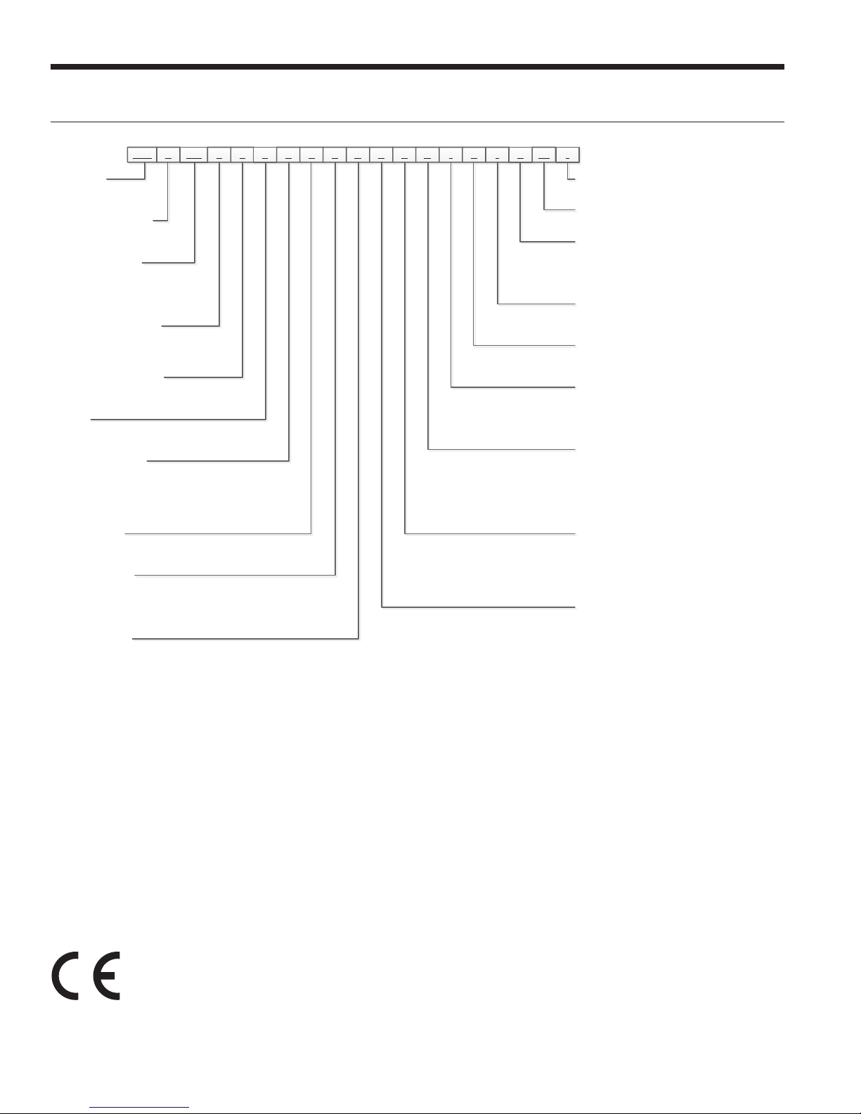
1-3 4 5-7 8 9 10
11 12 13 15
NBK V 015 T L 7 0 4 C A N14A16N17118A19120021SS
22-23*24
Model Nomenclature
Model Type
NBK – Envision
Compact 50Hz
Cabinet Configuration
V – Vertical
H - Horizontal
Unit Capacity (kW)
Single Speed
005, 017
Dual-Capacity
006, 009, 012, 015
Discharge Configuration
T – Top (Vertical)
E – End (Horizontal)
S – Side (Horizontal)
Return Air Configuration
L – Left
R – Right
Voltage
6 – 220-240/50/1 (005-017)
7 – 320-420/50/3 (006-017)
Refrigeration Option
0 – None
2 – HWG Only w/o Pump
G – Hot Gas Bypass
R – Hot Gas Reheat
B – Hot Gas Bypass w/Hot Gas Reheat
Blower Options
1 – Variable Speed ECM Blower
4 – 5-Speed ECM Blower
Water Coil Option
C – Copper
D – Insulated Copper
N – CuproNickel
P – Insulated CuproNickel
Sound Kit Option
A – None
B – Sound Kit
Note:
1 - Phase Guard Only Available on 380-420/50/3
2
Vintage
* - Factory Use Only
Non-Standard Options
SS – Standard
Drain Pan Option
0 – Composite, No Secondary Connection
1 – Composite, Secondary Connection
2 – Stainless Steel, No Secondary Connection
3 – Stainless Steel, Secondary Connection
Air Coil Option
3 – Standard
4 – AlumiSeal
Filter Option
A – MERV 4
B – MERV 13
Cabinet Option
0 – Unpainted Cabinet, Filter Rail
1 – Painted Cabinet, Filter Rail
2 – Unpainted Cabinet, 4-Sided Filter Rack
3 – Painted Cabinet, 4-Sided Filter Rack
Electrical Option
N – None
A – IntelliStart
E – IntelliStart and Disconnect
P – Phase Guard, No Disconnect
B – Phase Guard, Disconnect
D – No Phase Guard, Disconnect
Control Option
A – Aurora
E – Aurora
F – Aurora
Water Control Option
N – None
R – Water Flow Regulator
V – 2-Way Valve
B – 2-Way Valve w/ Water Flow Regulator
Rev.: 22 May 2014D
TM
1
®
Only
TM
Base Control (ABC)
TM
DDC
TM
DDC w/Lon
All Envision2 NBK 50Hz product is safety tested to CE standards and
performance tested in accordance with standard EN 14511-2.
4
General Installation Information
ENVISION2 COMPACT - 50 HZ INSTALLATION MANUAL
Safety Considerations
WARNING: Before performing service or
maintenance operations on a system, turn off main
power switches to the indoor unit. If applicable,
turn off the accessory heater power switch.
Electrical shock could cause personal injury.
Installing and servicing heating and air conditioning
equipment can be hazardous due to system pressure and
electrical components. Only trained and qualified service
personnel should install, repair or service heating and air
conditioning equipment. Untrained personnel can perform
the basic maintenance functions of cleaning coils and
cleaning and replacing filters. All other operations should
be performed by trained service personnel. When working on heating and air conditioning equipment, observe
precautions in the literature, tags and labels attached to the
unit and other safety precautions that may apply.
Follow all safety codes. Wear safety glasses and work
gloves. Use a quenching cloth for brazing operations and
have a fire extinguisher available.
Moving and Storage
Move units in the normal “up” orientation. Horizontal units
may be moved and stored per the information on the
packaging. Do not stack more than three units in total
height. Vertical units may be stored one upon another to
a maximum height of two units. Do not attempt to move
units while stacked. When the equipment is received, all
items should be carefully checked against the bill of lading
to be sure all crates and cartons have been received.
Examine units for shipping damage, removing the units
from the packaging if necessary. Units in question should
also be internally inspected. If any damage is noted, the
carrier should make the proper notation on the delivery
receipt, acknowledging the damage.
Unit Location
Locate the unit in an indoor area that allows for easy
removal of the filter and access panels. Location should
have enough space for service personnel to perform
maintenance or repair. Provide sufficient room to make
water, electrical and duct connection(s). If the unit is
located in a confined space, such as a closet, provisions
must be made for return air to freely enter the space
by means of a louvered door, etc. Any access panel
screws that would be difficult to remove after the unit
is installed should be removed prior to setting the unit.
On horizontal units, allow adequate room below the unit
for a condensate drain trap and do not locate the unit
above supply piping. Care should be taken when units are
located in unconditioned spaces to prevent damage from
frozen water lines and excessive heat that could damage
electrical components.
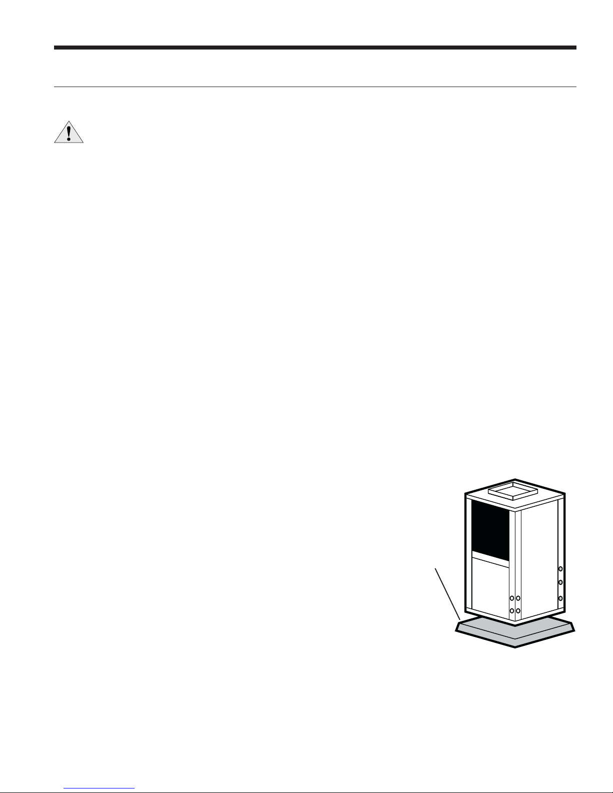
Installing Vertical Units
Prior to setting the unit in place, remove and discard the
compressor hold down shipping bolt located at the front of
the compressor mounting bracket.
Vertical units are available in left or right air return
configurations. Top flow vertical units should be mounted
level on a vibration absorbing pad slightly larger than the base
to provide isolation between the unit and the floor. It is not
necessary to anchor the unit to the floor (see figure below).
Vertical Unit Mounting
50.8 mm
PEX Foam
5
ENVISION2 COMPACT - 50 HZ INSTALLATION MANUAL
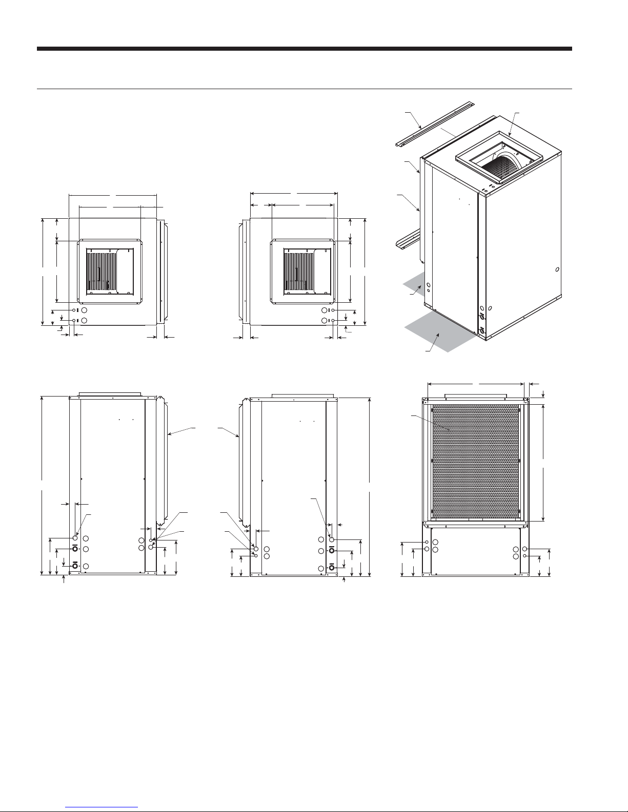
Vertical Dimensional Data
A
RN
S
Q
AIR COIL SIDE
P
B
AIR COIL SIDE
F
4
3
FRONT
1.4 in (3.5 cm)
M
M
G
Top View - Right Return Top View - Left Return
Air coil
A
N
FRONT
1.4 in (3.5 cm)
Standard filter rails for
open return applications
Deluxe filter rack for
ductable return applications
Air coil
Q
P
B
2' (61 cm)
G
Alternate
Service Access
4
3
F
2' (61 cm)
Service Access Left Return
(Right Return opposite side)
Air coil
ACCESS
PANEL
Isometric View - Left Return
U
Field installed
duct flange
T
W
ACCESS
PANEL
C
1.6 in (4.1 cm)
Condensate 3/4 in
PVC glue socket
1.6 in (4.1 cm)
5
H
2
E
1
D
6
8
1 in (25.4 mm)
1/2" (12.7 mm)
J
L
Power supply
knockout
Low voltage
knockout
L
K
Front View - Right Return
ACCESS
PANEL
Condensate
3/4 in PVC
glue socket
1.6 in (4.1 cm)
8
7
5
2
1
Front View - Left Return
1.6 in
(4.1 cm)
H
E
D
V
C
6
ACCESS
J
8
L
PANEL
8
7
L
K
Right View - Right Return
Left View - Left Return
6
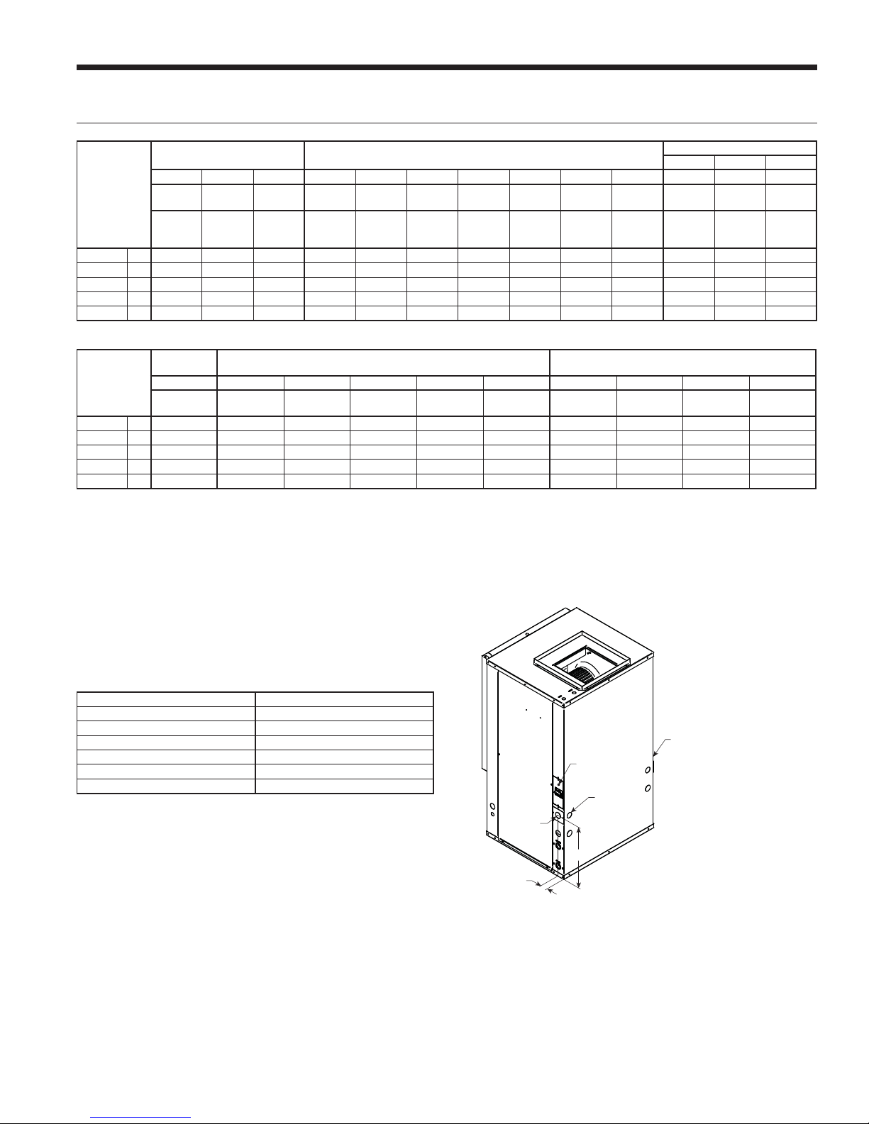
Vertical Dimensional Data cont.
ENVISION2 COMPACT - 50 HZ INSTALLATION MANUAL
Overall Cabinet Water Connections
Vertical
Models
005
006
009
012
015-017
Vertical
Models
005
006
009
012
015-017
Condensate is 3/4 in. PVC female glue socket and is switchable from side to front.
*Discharge flange is field installed and extends 25.4 mm from top of cabinet.
**Vertical units shipped with standard 50.8 mm (field adjustable to 25.4 mm) open application filter rack extending
55.88 mm from unit and is not suitable for duct connection. For ductable return connection applications, order the
deluxe 50.8 mm (field adjustable to 25.4 mm) duct collar/filter rack which extends 82.55 mm from the unit and is
suitable for duct connections.
12345 JKL
A B C D E F G H Loop Knockout
Width Depth Height* In Out HWG In HWG Out
cm 57.2 66.5 102.1 6.6 19.3 3.6 11.2 27.4 19.1 mm 22.2 mm 25.7 15.5 20.6
cm 57.2 66.5 112.3 6.6 19.3 3.6 11.2 27.4 19.1 mm 22.2 mm 25.7 15.5 20.6
cm 64.8 79.2 112.3 6.6 19.3 3.6 11.2 27.4 25.4 mm 22.2 mm 25.7 15.5 20.6
cm 64.8 79.2 122.4 6.6 19.3 3.6 11.2 27.4 25.4 mm 22.2 mm 25.7 15.5 20.6
cm 64.8 79.2 132.6 6.6 19.3 3.6 11.2 27.4 25.4 mm 22.2 mm 25.7 15.5 20.6
Discharge Connection
duct flange installed (±2.54 mm)
MNPQR S T U VW
Filter Rack
Width
cm 5.6 35.6 35.6 15.5 11.4 19.6 5.1 56.1 55.9 4.8
cm 5.6 35.6 35.6 15.5 11.4 19.6 5.1 56.1 66.3 4.6
cm 5.6 45.7 45.7 16.8 11.7 16.0 4.1 71.4 66.3 5.1
cm 5.6 45.7 45.7 16.8 11.7 16.0 4.1 71.4 76.2 5.1
cm 5.6 45.7 45.7 16.8 12.7 16.3 4.1 71.4 86.4 5.1
Supply
Width
Supply
Depth
Cond-
ensate
Water
FPT
HWG
Provi-
sions
**Return Connection
using deluxe filter rack (±2.54 mm)
Return
Depth
Electrical Knockouts
678
12.7 mm
cond
Low Volt-
age
12.7 mm
Low Volt-
Return
Height
cond
age
25.4 mm
Power
Supply
6/25/12
6/25/12
Vertical Disconnect
When using disconnect, do not use dimension L from the
standard vertical dimensional data. Use dimension LL from
the vertical disconnect dimensional data.
Vertical Models LL
005
006
009
012
015
017
Dimensions in cm 6/25/12
36.3
38.9
36.3
36.3
36.3
External
Power
Supply
1.8 in.
[4.6 cm]
Disconnect Located on this
Side for a Right Return
Disconnect
Location
Alternative
Power
Location
LL
Vertical Shown in
Left Return Configuration
7
ENVISION2 COMPACT - 50 HZ INSTALLATION MANUAL
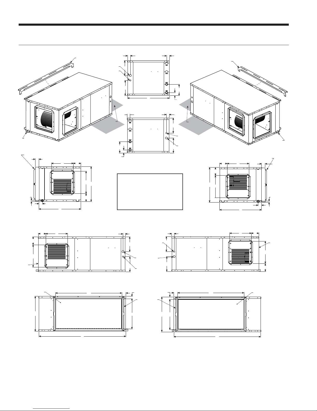
Horizontal Dimensional Data
Right Return
Condensate
"X" PVC size
End Discharge
Deluxe filter rack option shown
H
2.3 in. [5.8 cm]
FILTER RACK
AIR COIL SIDE
2.1 in. [5.3 cm]
Right Return
End Discharge
N
BLOWER
OUTLET
A
Standard filter rails
1 in. [2.5 cm] knockout
0.5 in. [1.3 cm] knockout
Front
AP
CMP
Service Access
Side Discharge
P
M
C
L
2' (61 cm)
1.7 in.
[5.3 cm]
K
J
E
D
AP = Alternate Service Panel
BP = Blower Service Panel
CP = Control Access Panel
CMP = Compressor Service Panel
CP
AP
A
RR Front View
1.7
CP
AP
LR Front View
Legend
1.7
1.7 in.
[5.3 cm]
E
D
J
Service Access
0.5 in. [1.3 cm]
knockout
1 in. [2.5 cm]
K
knockout
Standard filter rails
Front
AP
CMP
2' (61 cm)
Side Discharge
Deluxe filter rack option shown
P
N
L
C
M
BLOWER
OUTLET
2.1 in. [5.3 cm]
Left Return
End Discharge
Left Return
Condensate
"X" PVC size
End Discharge
2.3 in.
AIR COIL SIDE
A
[5.8 cm]
FILTER RACK
H
BP
Front
P
N
L
M
Air Coil
BLOWER
OUTLET
Right Return Side Discharge
C
Right Return Side View
J
K
T
R
1.5 in. [3.8 cm]
AP
CMP
S
Left Return Side Discharge
Q
B
Left Return Side View
1.5 in. [3.8 cm]
0.5 in. [1.3 cm]
K
AP
CMP
FILTER RACK CONNECTION FILTER RACK CONNECTION
B
J
SQ
R
Front
1 in. [2.5 cm]
knockout
0.5 in. [1.3 cm]
knockout
T
Deluxe filter
rack option
(shown)
knockout
Front
C
N
BLOWER
OUTLET
P
BP
M
L
Air Coil
Front
8
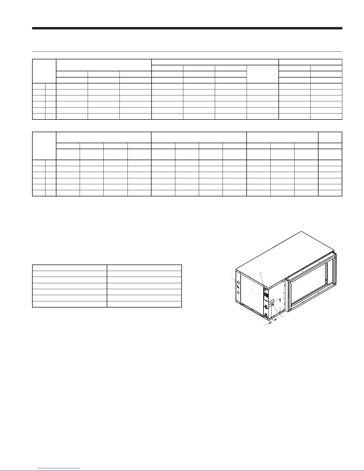
Horizontal Dimensional Data cont.
ENVISION2 COMPACT - 50 HZ INSTALLATION MANUAL
Overall Cabinet
Width
Supply
Depth
Horizontal
Models
005
cm 57.2 106.7 48.8 4.6 17.3 2.0 19.05 mm 23.1 18.0
006
cm 57.2 114.3 48.8 4.6 17.3 2.0 19.05 mm 23.4 18.0
009
cm 64.8 121.9 53.8 4.6 17.3 2.0 25.4 mm 23.4 23.1
012
cm 64.8 134.6 53.8 4.6 17.3 2.0 25.4 mm 23.4 23.1
015
cm 64.8 154.9 53.8 4.6 17.3 2.0 25.4 mm 23.4 23.1
017
cm 64.8 172.7 53.8 4.6 17.3 2.0 25.4 mm 23.4 23.1
Horizontal
Models
005
cm 17.0 26.7 23.9 12.4 69.6 42.2 5.1 3.6 108.6 63.8 54.4 1.9
006
cm 17.0 26.7 23.9 12.4 77.2 42.2 5.1 3.8 116.3 63.8 54.4 1.9
009
cm 12.4 34.5 33.5 11.7 89.9 47.2 5.8 3.6 124.0 71.4 62.0 1.9
012
cm 12.4 34.5 33.5 11.7 102.6 47.2 5.8 3.6 136.7 71.4 62.0 1.9
015
cm 12.4 34.5 33.5 11.7 115.3 47.2 5.8 3.6 157.0 71.4 62.0 1.9
017
cm 12.4 34.5 33.5 11.7 115.3 47.2 5.8 3.6 174.8 71.4 62.0 1.9
Horizontal units shipped with standard 50.8 mm (field adjustable to 25.4mm) open application filter rack extending 55.88 mm from
unit and is not suitable for duct connection. For ductable return connection applications, order the deluxe 50.8 mm (field adjustable
to 25.4 mm) duct collar/filter rack which extends 82.55 mm from the unit and is suitable for duct connections.
A B C D E H 12.7 mm cond 25.4 mm
Width Depth Height* In Out Condensate Low Voltage Power Supply
Discharge Connection
duct flange installed (±2.54mm)
LMNPQRS TUVWX
Supply
123
using deluxe filter rack option (±2.54 mm)
Return
Depth
Water Connections Electrical Knockouts
JK
Return Connection
Return
Height
Loop
Water FPT
Unit Hanger Dimensions PVC Size
6/25/12
6/25/12
Horizontal Disconnect
When using disconnect, do not use dimension K from the
standard horizontal dimensional data. Use dimension KK
from the horizontal disconnect dimensional data.
Horizontal Models KK
005
006
009
012
015
017
Dimensions in cm 6/25/12
23.4
23.4
28.4
25.9
28.4
25.9
Disconnect Located
on this Side for a
Left Return
2.1 in.
[5.3 cm]
Disconnect
Location
KK
Power Supply
Horizontal Shown in
Right Return Configuration
9
ENVISION2 COMPACT - 50 HZ INSTALLATION MANUAL
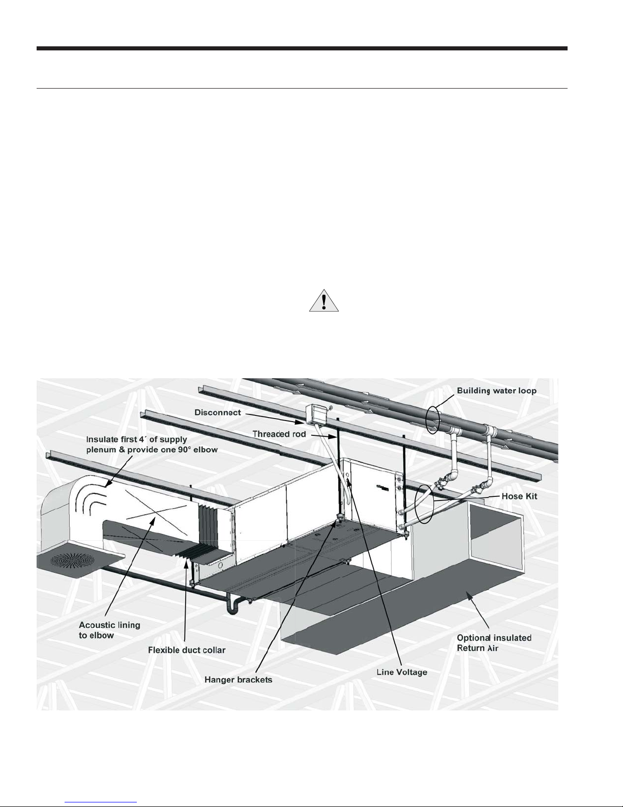
Installing Horizontal Units
Installing Horizontal Units
Remove and discard the compressor hold down shipping
bolt located at the front of the compressor mounting
bracket prior to setting the unit in place. Horizontal units
are available with side or end discharge.
NOTE: Left (Right) Return Side Discharge cannot be
converted to Left (Right) Return End Discharge or vice
versa, without additional custom sheet metal parts.
Horizontal units are normally suspended from a ceiling by
four (006-015 models) or five (017 model) 9.5 mm diameter
threaded rods. The rods are usually attached to the unit by
hanger bracket kits furnished with each unit.
Lay out the threaded rods per the Hanger Bracket
Dimensions table. Assemble the hangers to the unit as
shown. Securely tighten the brackets to the unit using the
weld nuts located on the underside of the bottom panel.
When attaching the hanger rods to the bracket, a double
nut is required since vibration could loosen a single nut. To
allow filter access, install hanger brackets as illustrated in
the Hanger Bracket Locations section. The unit should be
pitched approximately 6.35 mm towards the drain in both
directions to facilitate the removal of condensate. Use only
the bolts provided in the kit to attach hanger brackets. The
use of longer bolts could damage internal parts.
Some applications require the installation of horizontal
units on an attic floor. In this case, the unit should be set
in a full size secondary drain pan on top of a vibration
absorbing pad. The secondary drain pan prevents possible
condensate overflow or water leakage damage to the
ceiling. The secondary drain pan is usually placed on a
plywood base isolated from the ceiling joists by additional
layers of vibration absorbing material.
CAUTION: Do not use rods smaller than 9.5 mm
diameter since they may not be strong enough
to support the unit. The rods must be securely
anchored to the ceiling.
10
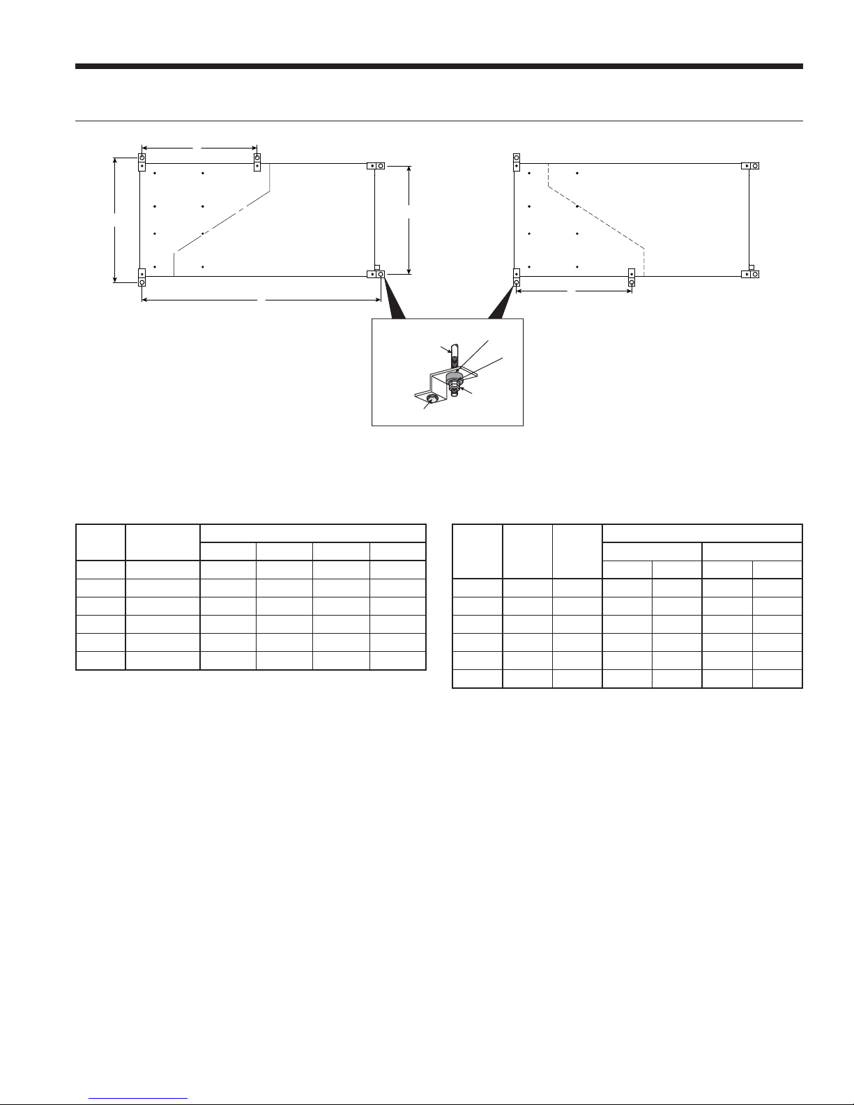
Hanger Bracket Locations
ENVISION2 COMPACT - 50 HZ INSTALLATION MANUAL
H
D
Compressor
Section
B
E
NOTE: Model size 017 will be shipped with six (6) hanger brackets. Only five(5) hanger brackets will be used on the unit. See the above
illustration for the fifth hanger bracket location. All other models will use four (4) hanger brackets.
Hanger Bracket Dimensions
Model
005
006
009
012
015
017
Dimensions are listed in cm. 6/25/12
Hanger Kit
Part Number
99S500A04 108.7 63.8 54.4 n/a
99S500A04 116.3 63.8 54.4 n/a
99S500A03 124.0 71.4 62.0 n/a
99S500A04 136.7 71.4 62.0 n/a
99S500A04 157.0 71.4 62.0 n/a
99S500A03 174.8 71.4 62.0 74.4
ABCD
Right
F
Air Handler
Section
G
A
Unit Hanger Dimensions
C
3/8”
Threaded Rod
(not supplied)
Bolt and
Lockwasher
E
Compressor
Section
D
H
Vibration Isolator
Washer
Hex Nuts
(not supplied)
Weight Distribution
Model
005
006
009
Weights are listed in kg. 6/25/12
Vertical
Weight
012
015
017
Horizontal
Weight
95 100 29 18 32 16
127 134 34 31 34 13
163 170 52 43 34 27
168 172 54 45 36 29
186 191 54 50 43 36
202 206 61 54 45 39
Left
Air Handler
Section
Horizontal Weight Distribution
Front Back
DEFG
G
F
11
ENVISION2 COMPACT - 50 HZ INSTALLATION MANUAL
Duct System
An air outlet collar is provided on vertical top flow units
and all horizontal units to facilitate a duct connection.
A flexible connector is recommended for discharge
and return air duct connections on metal duct systems.
Uninsulated duct should be insulated with a minimum of
1-inch duct insulation. Application of the unit to uninsulated
ductwork in an unconditioned space is not recommended
as the unit’s performance will be adversely affected.
If the unit is connected to existing ductwork, check the duct
system to ensure that it has the capacity to accommodate
the air required for the unit application. If the duct is too
small, as in the replacement of heating only systems, larger
ductwork should be installed. All existing ductwork should
be checked for leaks and repaired if necessary.
Water Piping
The proper water flow must be provided to each unit
whenever the unit operates. To assure proper flow, use
pressure/temperature ports to determine the flow rate.
These ports should be located at the supply and return
water connections on the unit. The proper flow rate cannot
be accurately set without measuring the water pressure
drop through the refrigerant-to-water heat exchanger.
The duct system should be sized to handle the design
airflow quietly and efficiently. To maximize sound
attenuation of the unit blower, the supply and return
plenums should include an internal duct liner of fiberglass
or constructed of ductboard for the first few feet. On
systems employing a sheet metal duct system, canvas
connectors should be used between the unit and the
ductwork. If air noise or excessive airflow is a problem, the
blower speed can be changed.
All source water connections on commercial units are
fittings that accept a male pipe thread (MPT). Insert the
connectors by hand, then tighten the fitting with a wrench
to provide a leakproof joint. When connecting to an open
loop (groundwater) system, thread any copper MPT fitting
into the connector and tighten in the same manner as
described above.
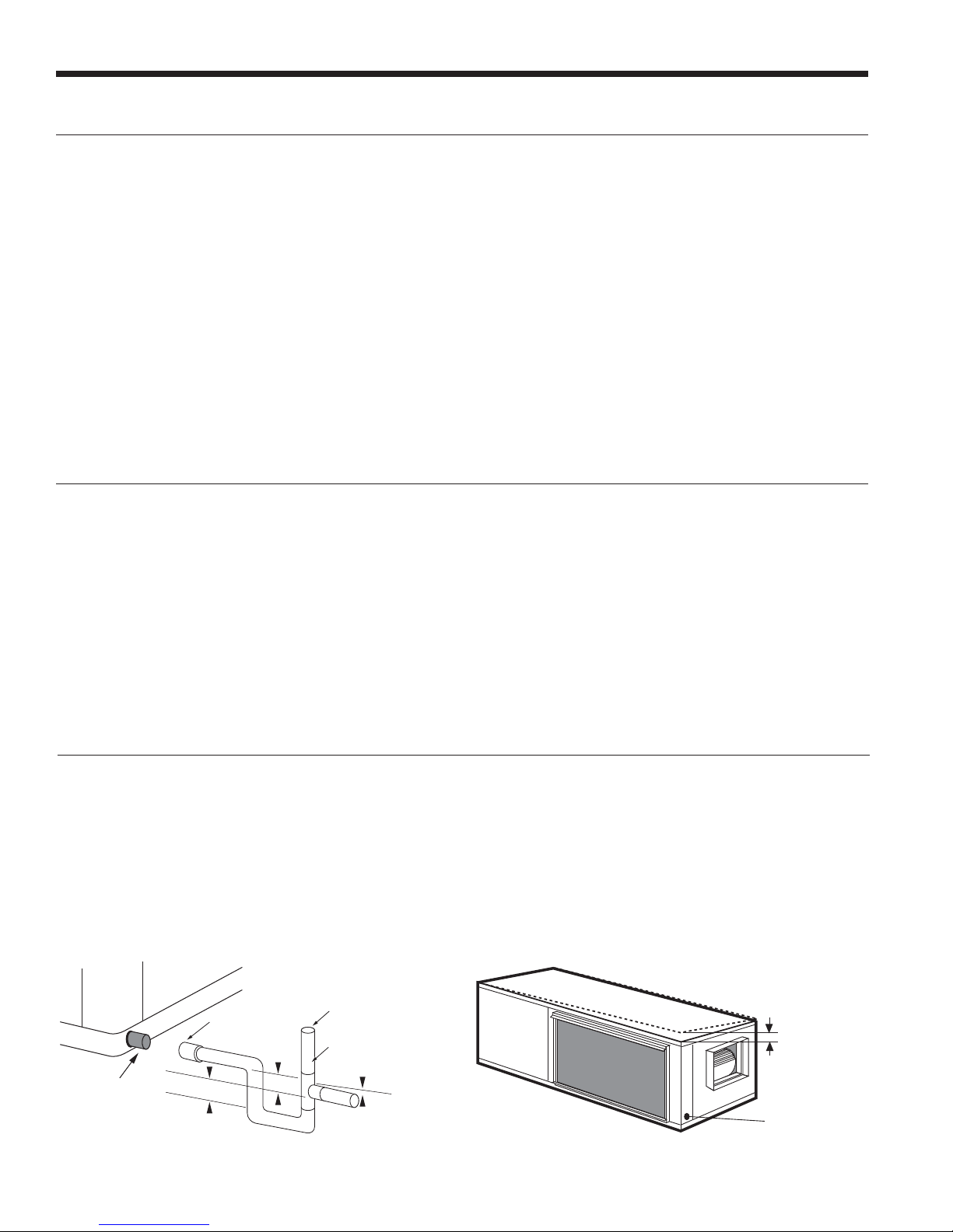
Condensate Drain
On vertical units, the internal condensate drain assembly
consists of a drain tube which is connected to the
drain pan, a 19.1 mm PVC female adapter and a flexible
connecting hose. The female adapter may exit either the
front or the side of the cabinet. The adapter should be
glued to the field-installed PVC condensate piping. On
vertical units, a condensate hose is inside all cabinets as a
trapping loop; therefore, an external trap is not necessary.
Vent (if needed)
PVC tube stub
10.4 mm per meter
PVC tube stub
PVC coupling
38.1 mm
38.1 mm
On horizontal units, a PVC stub or stainless steel tube
is provided for condensate drain piping connection. An
external trap is required (see below). If a vent is necessary,
an open stand pipe may be applied to a tee in the fieldinstalled condensate piping.
Unit Pitch for DrainHorizontal Drain Connection (Composite Drain Pan)
12.7 mm Pitch
Drain
12
Water Quality
ENVISION2 COMPACT - 50 HZ INSTALLATION MANUAL
In ground water situations where scaling could be heavy
or where biological growth such as iron bacteria will be
present, a closed loop system is recommended. The heat
exchanger coils in ground water systems may, over a period
with extremely hard water, the owner should be informed
that the heat exchanger may require occasional flushing.
Failure to adhere to the guidelines in the water quality table
could result in loss of warranty.
of time, lose heat exchange capabilities due to a buildup
of mineral deposits inside. These can be cleaned, but only
by a qualified service mechanic, as special solutions and
pumping equipment are required. Hot water generator coils
can likewise become scaled and possibly plugged. In areas
Material Copper 90/10 Cupronickel 316 Stainless Steel
pH Acidity/Alkalinity
Scaling
Corrosion
Iron Fouling
(Biological Growth)
Erosion
NOTES: Grains = ppm divided by 17
mg/L is equivalent to ppm
Calcium and
Magnesium Carbonate
Hydrogen Sulfide
Chlorides Less than 20 ppm Less than 125 ppm Less than 300 ppm
Carbon Dioxide Less than 50 ppm 10 - 50 ppm 10 - 50 ppm
Ammonia Less than 2 ppm Less than 2 ppm Less than 20 ppm
Ammonia Chloride Less than 0.5 ppm Less than 0.5 ppm Less than 0.5 ppm
Ammonia Nitrate Less than 0.5 ppm Less than 0.5 ppm Less than 0.5 ppm
Ammonia Hydroxide Less than 0.5 ppm Less than 0.5 ppm Less than 0.5 ppm
Ammonia Sulfate Less than 0.5 ppm Less than 0.5 ppm Less than 0.5 ppm
Total Dissolved Solids (TDS) Less than 1000 ppm 1000 - 1500 ppm 1000 - 1500 ppm
LSI Index +0.5 to -0.5 +0.5 to -0.5 +0.5 to -0.5
Iron, FE
Bacterial Iron Potential
Iron Oxide
Suspended Solids
Threshold Velocity
(Fresh Water)
Less than 0.5 ppm (rotten egg
smell appears at 0.5 ppm)
Sulfates Less than 125 ppm Less than 125 ppm Less than 200 ppm
Chlorine Less than 0.5 ppm Less than 0.5 ppm Less than 0.5 ppm
2
+ (Ferrous)
Less than 1 ppm, above this
level deposition will occur
Less than 10 ppm and filtered
for max. of 600 micron size
7 - 9 7 - 9 7 - 9
(Total Hardness)
less than 350 ppm
< 0.2 ppm < 0.2 ppm < 0.2 ppm
< 1.8 m/sec < 1.8 m/sec < 1.8 m/sec
Units with cupronickel heat exchangers are recommended
for open loop applications due to the increased resistance
to build-up and corrosion, along with reduced wear caused
by acid cleaning.
(Total Hardness)
less than 350 ppm
10 - 50 ppm Less than 1 ppm
Less than 1 ppm, above this
level deposition will occur
Less than 10 ppm and filtered
for max. of 600 micron size
(Total Hardness)
less than 350 ppm
Less than 1 ppm, above this
level deposition will occur
Less than 10 ppm and filtered
for max. of 600 micron size
2/22/12
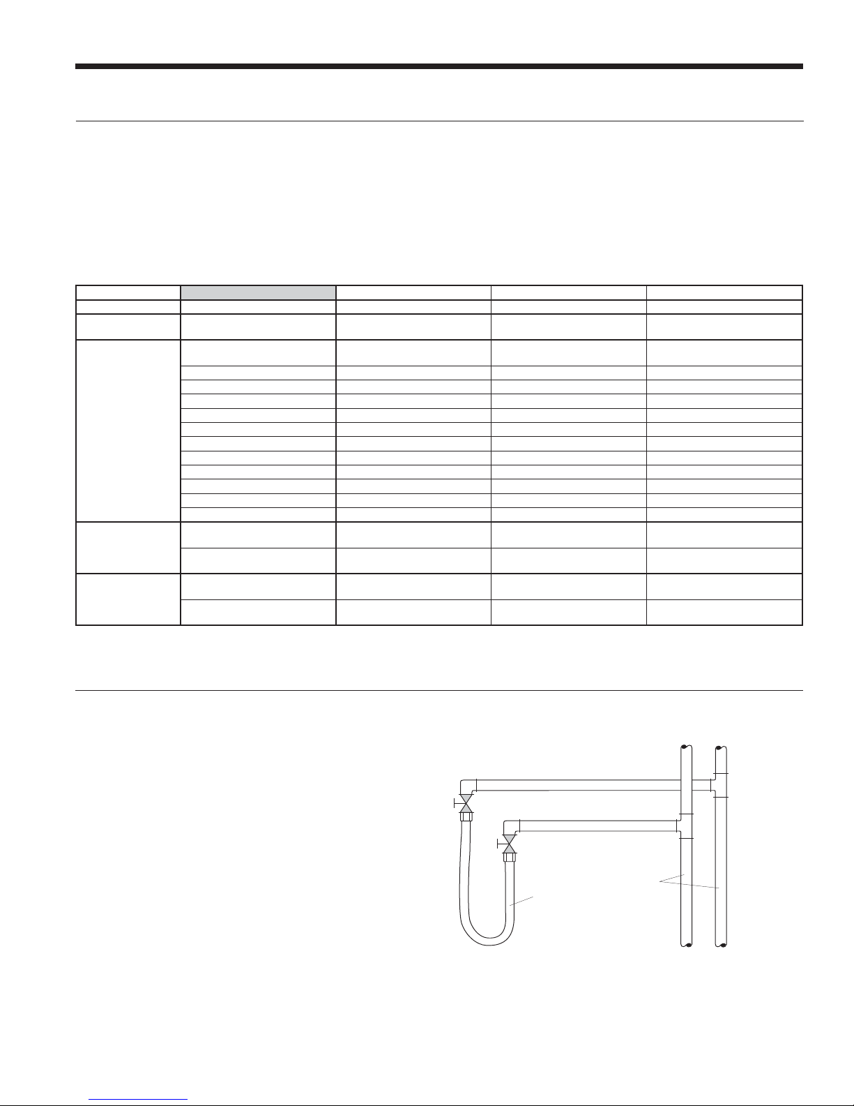
System Cleaning and Flushing
Cleaning and Flushing
Prior to start up of any heat pump, the water circulating
system must be cleaned and flushed of all dirt and debris.
If the system is equipped with water shutoff valves, the
supply and return runouts must be connected together
at each unit location (This will prevent the introduction of
dirt into the unit, see Flushing with Water Shutoff Valve
Equipped Systems illustration). The system should be filled
at the water make-up connection with all air vents open.
After filling, vents should be closed.
The contractor should start the main circulator with the
pressure reducing valve makeup open. Vents should be
checked in sequence to bleed off any trapped air and to
verify circulation through all components of the system.
As water circulates through the system, the contractor
should check and repair any leaks found in the piping
system. Drain(s) at the lowest point(s) in the system should
Flushing with Water Shutoff Valve Equipped Systems
Return Runout
Supply Runout
Mains
Rubber Hose
Runouts Initially
Connected Together
13
ENVISION2 COMPACT - 50 HZ INSTALLATION MANUAL
System Cleaning and Flushing cont.
be opened for initial flush and blowdown, making sure
water fill valves are set at the same rate. Check the pressure
gauge at the pump suction and manually adjust the makeup water valve to hold the same positive pressure both
before and after opening the drain valves. Flushing should
continue for at least two hours, or longer if required, until
drain water is clean and clear.
The supplemental heater and/or circulator pump, if used,
should be shut off. All drains and vents should be opened
to completely drain the system. Short-circuited supply and
return runouts should now be connected to the unit supply
and return connections.
Refill the system with clean water. Test the system water
for acidity and treat as required to leave the water slightly
alkaline (pH 7.5 to 8.5). The specified percentage of
antifreeze may also be added at this time. Use commercial
grade antifreeze designed for HVAC systems only.
Environol™ brand antifreeze is recommended.
Once the system has been filled with clean water and
antifreeze (if used), precautions should be taken to protect
the system from dirty water conditions. Dirty water will
result in system-wide degradation of performance, and
solids may clog valves, strainers, flow regulators, etc.
Additionally, the heat exchanger may become clogged
which reduces compressor service life and can cause
premature unit failure.
In boiler/tower application, set the loop control panel
set points to desired temperatures. Supply power to all
motors and start the circulating pumps. After full flow has
been established through all components including the
heat rejector (regardless of season), air vented and loop
temperatures stabilized, each of the units will be ready for
check, test and start up and for air and water balancing.
Ground Source Loop System Checkout
Once piping is completed between the unit pumping
system and ground loop, final purging and charging of
the loop is needed. A high pressure pump is needed to
achieve adequate flow velocity in the loop to purge air
and dirt particles from the loop itself. Antifreeze solution
is used in most areas to prevent freezing. Flush the
system adequately to remove as much air as possible;
then pressurize the loop to a static pressure of 276-345
kPa (summer) or 345-517 kPa (winter). This is normally
adequate for good system operation. Loop static pressure
may decrease soon after initial installation, due to pipe
expansion and loop temperature change. Running the
unit for at least 30 minutes after the system has been
completely purged of air will allow for the “break-in”
period. It may be necessary to adjust static loop pressure
(by adding water) after the unit has run for the first time.
Loop static pressure will also fluctuate with the seasons.
Pressures will be higher in the winter months than during
the cooling season. This fluctuation is normal and should be
considered when charging the system initially.
Ensure the pump provides adequate flow through the unit
by checking pressure drop across the heat exchanger.
Usually 0.14-0.19 L/s of flow per ton of cooling capacity is
recommended in earth loop applications.
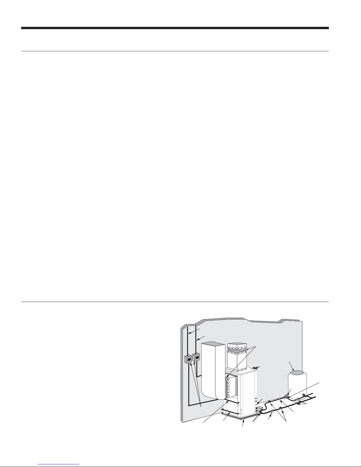
Open Loop Ground Water Systems
Typical open loop piping is shown below. Always maintain
water pressure in the heat exchanger by placing water
control valves at the outlet of the unit to prevent mineral
precipitation. Use a closed, bladder-type expansion tank
to minimize mineral formation due to air exposure. Insure
proper water flow through the unit by checking pressure
drop across the heat exchanger and comparing it to the
figures in unit capacity data tables in the specification
catalog. 0.09-0.13 L/s of flow per ton of cooling capacity is
recommended in open loop applications. Due to only minor
differences in flow rate from low to high, only one solenoid
valve should be used. The valve should be sized for full flow.
Discharge water from the unit is not contaminated in any
manner and can be disposed of in various ways, depending
on local codes, i.e. recharge well, storm sewer, drain field,
adjacent stream or pond, etc. Most local codes forbid the use
of sanitary sewer for disposal. Consult your local building and
zoning departments to assure compliance in your area.
Open System - Groundwater Application
Unit Supply
Aux. Heat Supply
Flexible
Duct Collar
Hot Water Generator
Connections
Drain
Disconnects
(IfApplicable)
Compressor
Line Voltage
Low Voltage
to Thermostat
and Valve
Vibration
Absorbing Pad
P/T Plugs
Strainer
14
Rubber Bladder
Expansion Tank
Solenoid
Valve
valve while acid flushing)
Boiler Drains
For HX Flushing
Flow Control
(on outlet of
Solenoid Valve)
Water Out
Shut Off Valves
Shut Off Valves
(to isolate solenoid
Valve
Water In
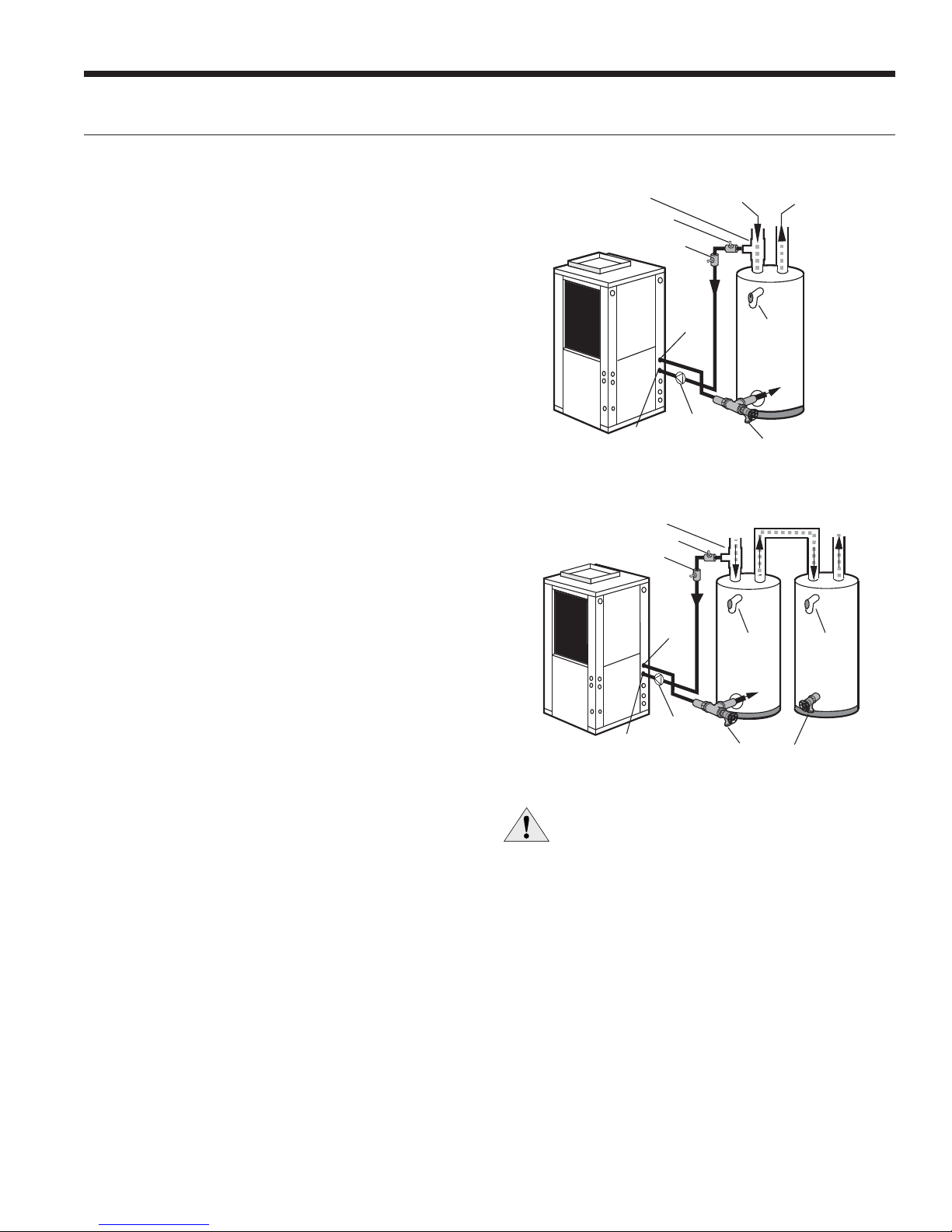
Hot Water Generator Connections
ENVISION2 COMPACT - 50 HZ INSTALLATION MANUAL
The heat reclaiming hot water generator coil is of vented
double-wall copper construction and is suitable for
potable water.
To maximize the benefits of the hot water generator a
minimum 189 L water heater is recommended. For higher
demand applications, use an 303 L water heater or two
189 L water heaters connected in a series as shown below.
Electric water heaters are recommended. Make sure all
local electrical and plumbing codes are met for installing
a hot water generator. A water softener is recommended
with hard water (greater than 0.65 g or 170 total hardness).
Water Tank Preparation
To install a unit with a hot water generator, follow these
installation guidelines.
1. Turn off the power to the water heater.
2. Attach a water hose to the water tank drain connection
and run the other end of the hose to an open drain
or outdoors.
3. Close the cold water inlet valve to the water heater tank.
4. Drain the tank by opening the valve on the bottom of the
tank, then open the pressure relief valve or hot water faucet.
5. Flush the tank by opening the cold water inlet valve to
the water heater to free the tank of sediments. Close
when draining water is clear.
6. Disconnect the garden hose and remove the drain valve
from the water heater.
7. Refer to Plumbing Installation and Hot Water
Generator Startup.
Typical Hot Water Generator Installation
19.1mm x 19.1mm x 12.7mm Tee
Ball Valve
Vent
HWG
Water Out
Field Installed
HWG Pump
HWG
Water In
Cold
Water In
Drain Valve
P/T Relief
Valve
Water Out
In
Hot
Hot Water Generator Installation In Preheat Tank
Cold
19.1mm x 19.1mm x 12.7mm Tee
Ball Valve
Vent
Water Out
Field Installed
HWG
Water In
HWG
HWG Pump
Water In
P/T Relief
Valve
Drain Valve
In
NOTE: This configuration maximizes hot water generator
capability.
Hot
Water Out
P/T Relief
Valve
Plumbing Installation
1. Inspect the dip tube in the water heater cold inlet
for a check valve. If a check valve is present it must
be removed or damage to the hot water generator
circulator will occur.
2. Remove drain valve and fitting.
3. Thread the 19.1 mm NPT x 89 mm brass nipple into the
water heater drain port.
4. Attach the center port of the 19.1 mm FPT tee to the
opposite end of the brass nipple.
5. Attach the 12.7 mm copper to 19.1 mm NPT adaptor to
the side of the tee closest to the unit.
6. Install the drain valve on the tee opposite the adaptor.
7. Run interconnecting tubing from the tee to HWG
water out.
CAUTION: Elements will burn out if energized dry.
8. Cut the cold water “IN” line going to the water heater.
9. Insert the reducing solder tee in line with cold water
“IN” line as shown.
10. Run interconnecting copper tubing between the unit
DHW water “IN” and the tee (12.7 mm nominal). The
recommended maximum distance is 9.1 m.
11.
To prevent air entrapment in the system, install a vent
coupling at the highest point of the interconnecting lines.
12. Insulate all exposed surfaces of both connecting water
lines with 9.5 mm wall closed cell insulation.
NOTE: All plumbing and piping connections must comply
with local plumbing codes.
15

ENVISION2 COMPACT - 50 HZ INSTALLATION MANUAL
Hot Water Generator Connections cont.
Hot Water Generator Startup
1. Make sure the power is off to the heat pump. Connect
the wire from the hot water generator pump to T1 on
the contactor.
2. Close the drain valve to the water heater.
3. Open the cold water supply to the tank.
4. Open a hot water faucet in the building to bleed air
from the system. Close when full.
5. Open the pressure relief valve to bleed any remaining
air from the tank, then close.
6. If so equipped, turn the venting (burping) screw in the
center of the pump two (2) turns open (water will drip out),
wait until all air is purged from the pump, then tighten the
plug. Use vent couplings to bleed air from the lines.
7. Carefully inspect all plumbing for water leaks and
correct as required.
8. Before restoring electrical supply to the water heater,
adjust the temperature setting on the tank.
• On tanks with both upper and lower elements,
the lower element should be turned down to
the lowest setting, approximately 37.8°C. The
upper element should be adjusted to 48.9°C to
54.4°C. Depending upon the specific needs of
the customer, you may want to adjust the upper
element differently.
• On tanks with a single element, lower the
thermostat setting to 48.9°C.
9. After the thermostat(s) is adjusted, replace the access
cover and restore electrical supply to the water heater.
10. Make sure that any valves in the hot water generator
circuit are open.
11. Turn on the unit to heating.
12. The HWG pump should be running. When the pump
is first started, turn the venting (burping) screw (if
equipped) in the center of the pump two (2) turns open
until water dribbles out, then replace. Allow the pump
to run for at least five minutes to ensure that water has
filled the circulator properly.
13. The temperature difference between the water entering
and leaving the hot water generator should be 2.8°C to
8.3°C. The water flow should be approximately 0.007
L/S per KW of nominal cooling.
14. Allow the unit to heat water for 15 to 20 minutes to be
sure operation is normal.
CAUTION: Never operate the HWG circulating
pump while dry. If the unit is placed in operation
before the hot water generator piping is
connected, be sure that the pump wires are
disconnected from the contactor.
16
Freeze Detection
ENVISION2 COMPACT - 50 HZ INSTALLATION MANUAL
For Aurora Base Control, set SW2-1, FP1, on the printed
circuit board for applications using a closed loop antifreeze
solution to -9.4°C. On applications using an open loop/
ground water system (or closed loop no antifreeze), set this
dip switch to -1.1°C, the factory default setting. (Refer to the
Dip Switch Field Selection table).
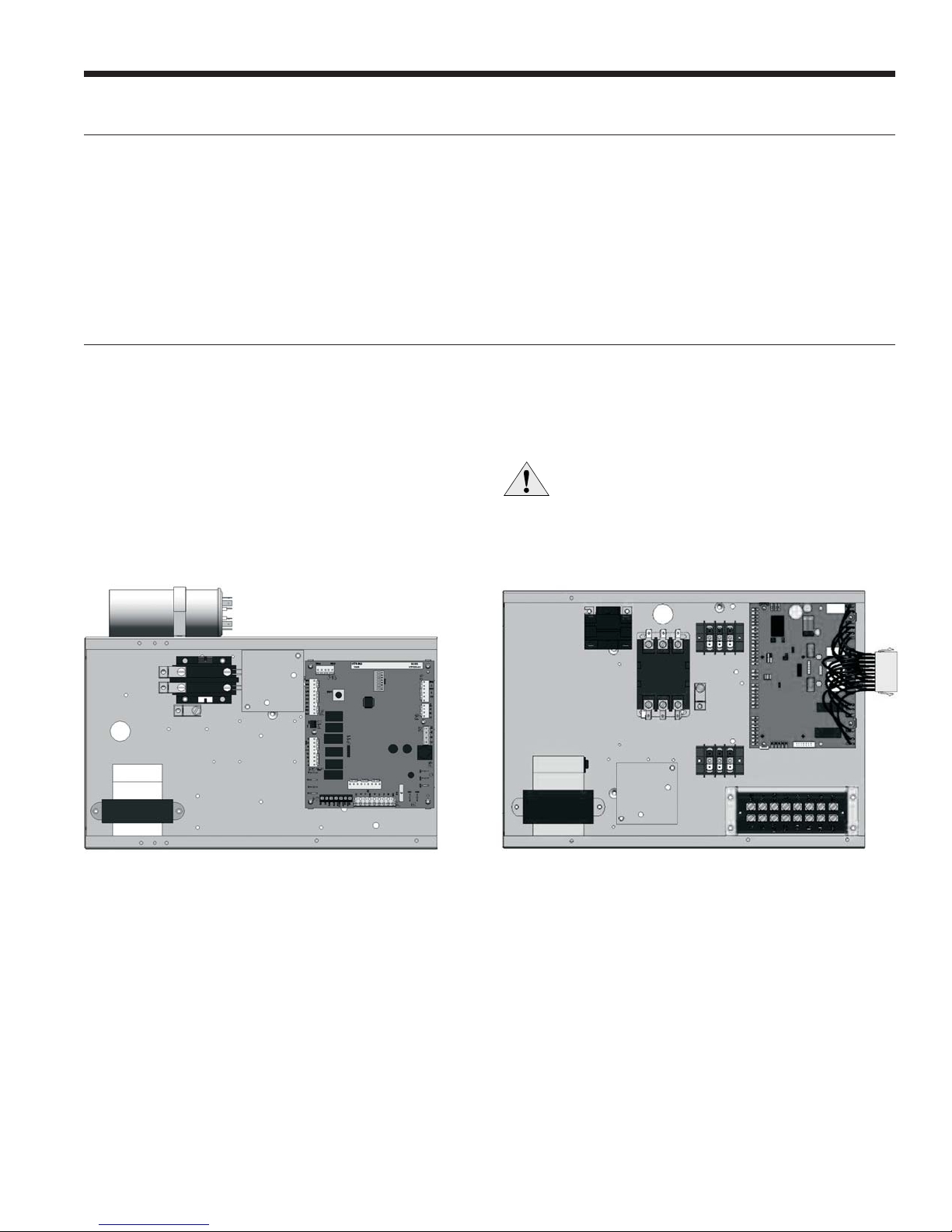
Electrical Connections
General
Be sure the available power is the same voltage and phase
as that shown on the unit serial plate. Line and low voltage
wiring must be done in accordance with local codes or the
National Electric Code, whichever is applicable.
Power Connection
Connect the incoming line voltage wires to L1 and L2 of the
contactor for single-phase unit. Consult the Electrical Data
tables for correct fuse sizes.
Aurora Base Control Box
For FX10 board, the “red” wire must be removed from PB2-3
to change from -1.1°C, the factory default setting, to -9.4°C.
220 Volt Operation
All 220-240 units are factory wired for 240 volt operation.
For 220 volt operation, the red and blue transformer wires
must be switched on terminal strip PS.
CAUTION: When installing a unit with a
variable speed ECM blower motor in 420/50/3
voltage, a neutral wire is required to allow
proper unit operation.
FX10 Control Box
17
 Loading...