

Page 1
Water Source/Geothermal Heat Pump
7 to 25 Tons
Installation Information
Water Piping Connections
Electrical Connections
Startup Procedures
Preventive Maintenance
Envision 7-25 Tons Installation Manual
IM1021ANA 01/15
Page 2

Table of Contents
Model Nomenclature. . . . . . . . . . . . . . . . . . . . . . . . . . . . . . . . . . . . . . . . . . . . . . . . . . . . . . . . . . . 4
General Installation Information . . . . . . . . . . . . . . . . . . . . . . . . . . . . . . . . . . . . . . . . . . . . . . . . . 5
Vertical Dimensions. . . . . . . . . . . . . . . . . . . . . . . . . . . . . . . . . . . . . . . . . . . . . . . . . . . . . . . . . . .6-7
Horizontal Dimensions . . . . . . . . . . . . . . . . . . . . . . . . . . . . . . . . . . . . . . . . . . . . . . . . . . . . . . . . . 8
Installing Horizontal Units . . . . . . . . . . . . . . . . . . . . . . . . . . . . . . . . . . . . . . . . . . . . . . . . . . . . 9-10
Installating Vertical Units . . . . . . . . . . . . . . . . . . . . . . . . . . . . . . . . . . . . . . . . . . . . . . . . . . . . . . . 11
Water Quality . . . . . . . . . . . . . . . . . . . . . . . . . . . . . . . . . . . . . . . . . . . . . . . . . . . . . . . . . . . . . . . . .12
System Cleaning and Flushing. . . . . . . . . . . . . . . . . . . . . . . . . . . . . . . . . . . . . . . . . . . . . . . . . . .13
Electrical Connections . . . . . . . . . . . . . . . . . . . . . . . . . . . . . . . . . . . . . . . . . . . . . . . . . . . . . . . . .14
Electrical Data . . . . . . . . . . . . . . . . . . . . . . . . . . . . . . . . . . . . . . . . . . . . . . . . . . . . . . . . . . . . . . . . 15
Blower Performance Data . . . . . . . . . . . . . . . . . . . . . . . . . . . . . . . . . . . . . . . . . . . . . . . . . . . 16-25
ENVISION 7-25 TONS INSTALLATION MANUAL
Wiring Schematics. . . . . . . . . . . . . . . . . . . . . . . . . . . . . . . . . . . . . . . . . . . . . . . . . . . . . . . . . 26-27
Optional FX10 Microprocessor Control . . . . . . . . . . . . . . . . . . . . . . . . . . . . . . . . . . . . . . . .28-37
Blower Drive Sheaves . . . . . . . . . . . . . . . . . . . . . . . . . . . . . . . . . . . . . . . . . . . . . . . . . . . . . . . . . 38
Unit Startup . . . . . . . . . . . . . . . . . . . . . . . . . . . . . . . . . . . . . . . . . . . . . . . . . . . . . . . . . . . . . . . . . 39
Operating Parameters. . . . . . . . . . . . . . . . . . . . . . . . . . . . . . . . . . . . . . . . . . . . . . . . . . . . . . . . . 40
Pressure Drop. . . . . . . . . . . . . . . . . . . . . . . . . . . . . . . . . . . . . . . . . . . . . . . . . . . . . . . . . . . . . . . . 40
Startup/Troubleshooting Form . . . . . . . . . . . . . . . . . . . . . . . . . . . . . . . . . . . . . . . . . . . . . . . . . .41
Preventive Maintenance . . . . . . . . . . . . . . . . . . . . . . . . . . . . . . . . . . . . . . . . . . . . . . . . . . . . . . . 42
Replacement Procedures . . . . . . . . . . . . . . . . . . . . . . . . . . . . . . . . . . . . . . . . . . . . . . . . . . . . . . 42
Page 3
ENVISION 7-25 TONS INSTALLATION MANUAL
COMMERCIAL
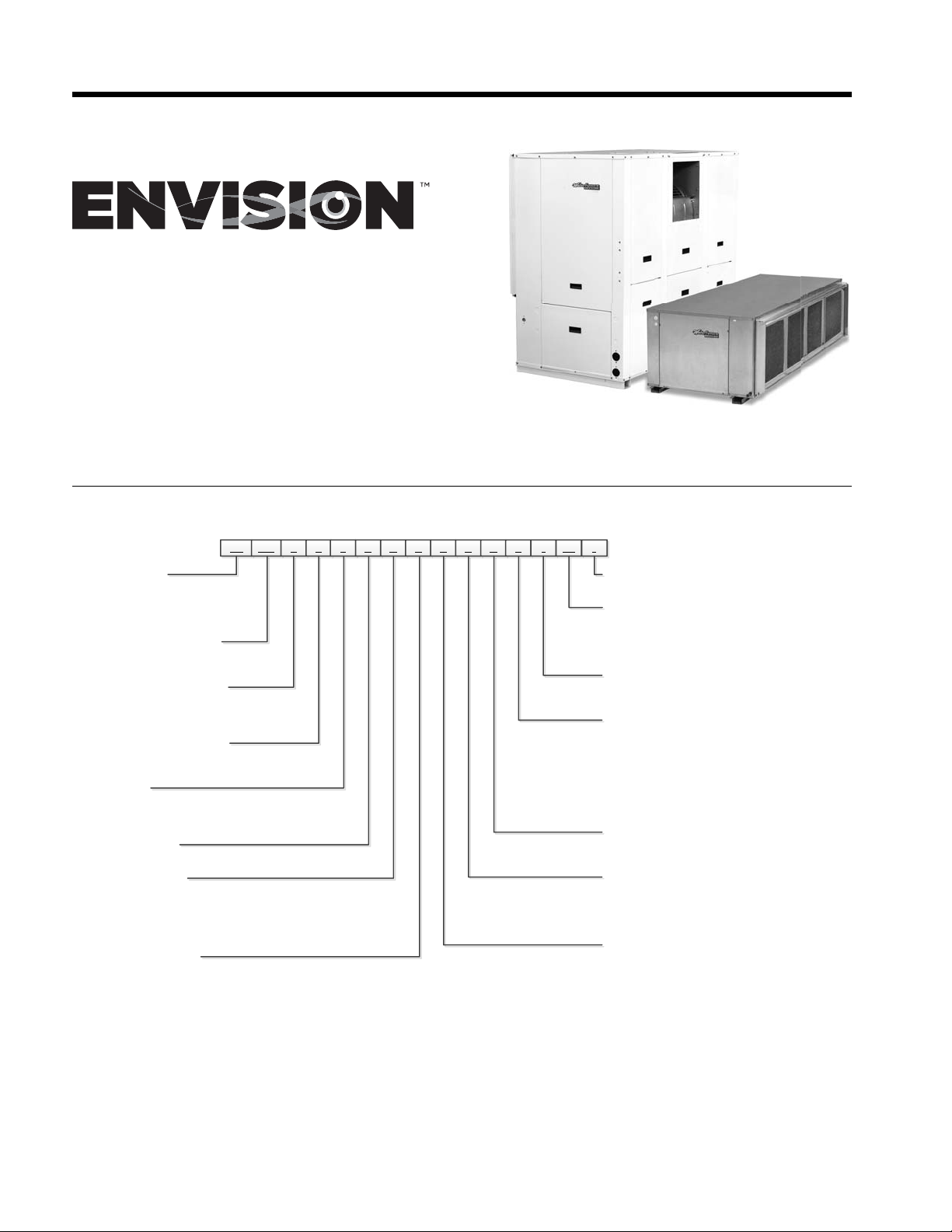
Model Nomenclature
1-2 3-5 6 7 8
NL
120 T L 3 0 A C A N12N14415116SS
Model Type
NL – Envision Series
(Low Temp)
NX – Envision Series
(Extended Range)
Unit Capacity (MBTUH)
080, 095, 120, 160
180, 240, 300
Discharge Configuration
T – Top Upflow (Vertical)
E – End Discharge (Horizontal)
S – Discharge Side (Horizontal)
Return Air Configuration
L – Left
R – Right
Voltage
3 – 208-230/60/3
4 – 460/60/3
5 – 575/60/3
Future Option
0 – Future
Blower Options
A – Standard Static, Standard Motor
B – Low Static, Standard Motor
C – High Static, Standard Motor
D – Standard Static, Large Motor
E – High Static, Large Motor
Water Coil Option
C – Copper
N – CuproNickel
1
2
2,3
3
91011 13
17-18*19
Vintage
* - Factory Use Only
Non-Standard Options
SS – Standard
QP – 2" MERV 13 Filter
SF – Stainless Steel Drain Pan
SG – 2" MERV 13 Filter, Stainless Steel Drain Pan
Air Coil/Insulation Option
3 – Uncoated
4 – AlumiSeal
Control Option
4 – FX10 Standard without Communication
5 – FX10 with Open N2 Communication
6 – FX10 with Lonworks Communication
7 – FX10 with BacNet Communication
8 – FX10 Standard with User Interface
9 – FX10 with Open N2 & User Interface
0 – FX10 with Lonworks & User Interface
3 – FX10 with BacNet & User Interface
Water Control Option
N – None
V – Two-Way Valve
Hot Gas Bypass/Reheat Option
N – None
G – Hot Gas Bypass
R – Hot Gas Reheat
B – Hot Gas Bypass w/Hot Gas Reheat
Sound Kit Option
A – None
B – Sound Kit
TM
4
4
Notes:
1 – Not available on vertical NL/NX095, 180, horizontal NL/NX080
2 – Not available on vertical NL/NX080, 160
3 – Not available on horizontal NL/NX120, vertical NL/NX300
4 – Not available on vertical NL/NX160-300. Stainless steel is standard on vertical NL/NX160-300
4
Rev.: 14 November 2014D
Page 4
ENVISION 7-25 TONS INSTALLATION MANUAL
General Installation Information
Safety Considerations
WARNING: Before performing service or maintenance operations on a system, turn off main power switches to
the indoor unit. If applicable, turn off the accessory heater power switch. Electrical shock could cause personal
injury.
Installing and servicing heating and air conditioning equipment can be hazardous due to system pressure and electrical
components. Only trained and qualified service personnel should install, repair or service heating and air conditioning
equipment. Untrained personnel can perform the basic maintenance functions of cleaning coils and cleaning and
replacing filters. All other operations should be performed by trained service personnel. When working on heating and
air conditioning equipment, observe precautions in the literature, tags and labels attached to the unit and other safety
precautions that may apply.
Follow all safety codes. Wear safety glasses and work gloves. Use a quenching cloth for brazing operations and have a fire
extinguisher available.
Moving and Storage
Move units in the normal “up” orientation. Horizontal units may be moved and stored per the information on the packaging.
Do not stack more than three units in total height. Vertical units may be stored one upon another to a maximum height
of two units. Do not attempt to move units while stacked. When the equipment is received, all items should be carefully
checked against the bill of lading to be sure all crates and cartons have been received. Examine units for shipping damage,
removing the units from the packaging if necessary. Units in question should also be internally inspected. If any damage is
noted, the carrier should make the proper notation on the delivery receipt, acknowledging the damage.
Unit Location
Locate the unit in an indoor area that allows for easy removal of the filter and access panels. Location should have enough
space for service personnel to perform maintenance or repair. Provide sufficient room to make water, electrical and duct
connection(s). If the unit is located in a confined space, such as a closet, provisions must be made for return air to freely
enter the space by means of a louvered door, etc. Any access panel screws that would be difficult to remove after the
unit is installed should be removed prior to setting the unit. On horizontal units, allow adequate room below the unit for
a condensate drain trap and do not locate the unit above supply piping. Care should be taken when units are located
in unconditioned spaces to prevent damage from frozen water lines and excessive heat that could damage electrical
components.
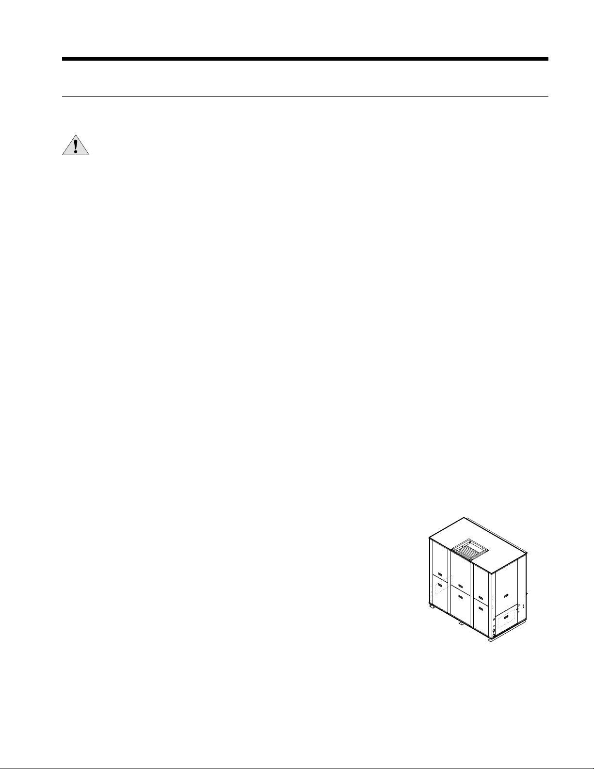
Installing Vertical Units
Prior to setting the unit in place, remove and discard the compressor hold down
shipping bolt located at the front of the compressor mounting bracket.
Vertical units are available in left or right air return configurations. Top flow vertical
units should be mounted level on a vibration absorbing pad slightly larger than the
base to provide isolation between the unit and the floor. It is not necessary to anchor
the unit to the floor (see right).
Figure 1: Vertical Unit Mounting
(NXV/NLV 080-300)
5
Page 5
ENVISION 7-25 TONS INSTALLATION MANUAL
N
8
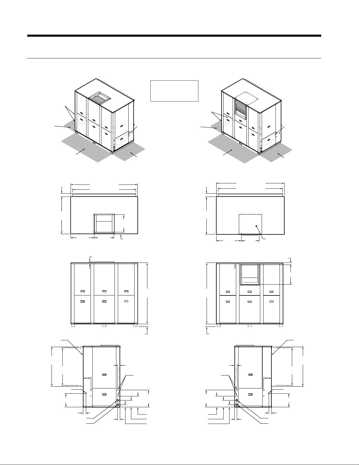
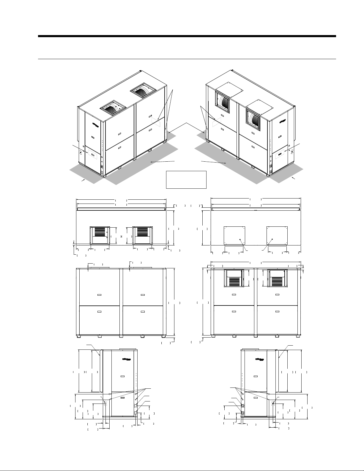
Vertical Dimensions
7-10 Tons
CONTROL BOX
AND WATER
LEFT RETURN
2’ PRIMARY
SERVICE ACCESS
FOR LEFT RETURN
2’ SECONDARY
SERVICE ACCESS
TOP DISCHARGE
Legend
AP = Alternate Service Panel
BP = Blower Service Panel
CP = Control Access Panel
CMP = Compressor Service Panel
CONTROL BOX AND WATER
LEFT RETURN
CP CP
AP
CMP
2.9 in
[7.4 cm]
61.3 in [155.8 cm]
58.1 in [147.6 cm]
CONTROL BOX
RIGHT RETURN
2’ PRIMARY
SERVICE ACCESS
FOR RIGHT RETURN
2’ PRIMARY
SERVICE ACCESS
FOR LEFT RETURN
TOP VIEW
34.1 in
[86.6 cm]
16.1 in
[40.9 cm]
Left or Right Return
AP
CMP
2’ SECONDARY
SERVICE ACCESS
2.9 in
[7.4 cm]
34.1 in
[86.6 cm]
SIDE DISCHARGE
61.3 in [155.7 cm]
58.1 in [147.6 cm]
CONTROL BOX
RIGHT RETURN
CPCP
2’ PRIMARY
SERVICE ACCESS
FOR RIGHT RETURN
AIR COILS
36.3 in
[92.2 cm]
34.4 in
[87.4 cm]
DRAIN CONNECTION
12.5 in [31.8 cm]
[54.9 cm]
7.2 in
[18.3 cm]
21.6 in
18.1 in
[46.0 cm]
1 in [2.5 cm]
1.42 in
[3.6 cm]
SIDE VIEW
Left or Right Return
2 in [5.1 cm]
56 in
[142.2 cm]
56 in
[142.2 cm]
LEFT RETURN RIGHT RETURN
2.2 in
[5.6 cm]
TOP OR SIDE DISCHARGE
ELECTRICAL
CONNECTIONS
15.6 in
[39.6 cm]
ELECTRICAL
CONNECTIONS
15.6 in
[39.6 cm]
22.6 in
[57.4 cm]
2 in [5.1 cm]
2.2 in
[5.6 cm]
16.1 in
[40.9 cm]
TOP PANEL
COVER
1.8 in [4.6 cm]
7.2 in
[18.3 cm]
12.5 in [31.8 cm]
18.1 in [46 cm]
AIR COILS
36.3 in
[92.2 cm]
34.4 in
[87.4 cm]
DRAIN CONNECTIO
2.6 in [6.6 cm]
WATER OUT
WATER IN
2.0 in
[5.1 cm]
10.1 in [25.7 cm]
4.0 in [10.2 cm]
2.2 in [5.6 cm]
10.1 in [25.7 cm]
4.0 in [10.2 cm]
2.2 in [5.6 cm]
6
2.0 in
[5.1 cm]
2.6 in [6.6 cm]
WATER OUT
WATER IN
REV 2/11/0
Page 6
Vertical Dimensions cont.
13-25 Tons
TOP DISCHARGE
CONTROL BOX
AND WATER
RIGHT RETURN
CONTROL BOX
AND WATER
LEFT RETURN
2’ PRIMARY
SERVICE ACCESS
ENVISION 7-25 TONS INSTALLATION MANUAL
SIDE DISCHARGE
CONTROL BOX
LEFT RETURN
2’ PRIMARY
SERVICE ACCESS
CPCP
2’ SECONDARY
AP
16.0 in
40.6 cm
CMP
1.0 in
2.5 cm
18.0 in
45.7 cm
14.2 in
36.1 cm
CP CP
88.1 in
223.8 cm
86.3 in
219.1 cm
16.0 in
40.6 cm
18.0 in
14.2 in
45.7 cm
36.1 cm
1.5 in
3.7 cm
1.0 in
2.5 cm
SERVICE ACCESS
Legend
AP = Alternate Service Panel
BP = Blower Service Panel
CP = Control Access Panel
CMP = Compressor Service Panel
2.9 in
2.9 in
7.3 cm
7.3 cm
TOP VIEW
L or R Return
34.0 in
86.4 cm
1.5 in
3.7 cm
SIDE VIEW
L or R Return
66.0 in
167.5 cm
34.0 in
86.4 cm
66.0 in
167.5 cm
13.8 in
35.1 cm
2.0 in
5.1 cm
18.0 in
45.8 cm
AP
CMP
TOP PANEL
COVER
16.0 in
40.6 cm
88.1 in
223.8 cm
86.3 in
219.1 cm
88.1 in
223.8 cm
16.0 in
40.6 cm
18.0 in
45.8 cm
CONTROL BOX
RIGHT RETURN
2’ PRIMARY
SERVICE ACCESS
13.8 in
35.1 cm
2.0 in
5.1 cm
AIR COILS
41.8 in
106.2 cm
DRAIN CONNECTION
24.5 in
62.2 cm
19.0 in
48.2 cm
40.4 in
102.6 cm
15.2 in
38.7 cm
2.6 in
6.5 cm
6.5 in
16.5 cm
1.7 in
4.4 cm
2.0 in
5.1 cm
LEFT RETURN
TOP OR SIDE DISCHARGE
ELECTRICAL
CONNECTIONS
WATER OUT
WATER IN
13.0 in
33.0 cm
6.0 in
15.2 cm
2.0 in
5.1 cm
RIGHT RETURN
7
ELECTRICAL
CONNECTIONS
WATER OUT
WATER IN
13.0 in
33.0 cm
6.0 in
15.2 cm
1.7 in
4.4 cm
AIR COILS
40.4 in
41.8 in
102.6 cm
106.2 cm
DRAIN CONNECTION
19.0 in
15.2 in
48.2 cm
38.7 cm
2.6 in
6.5 cm
6.5 in
16.5 cm
24.5 in
62.2 cm
REV 8/16/07
Page 7
ENVISION 7-25 TONS INSTALLATION MANUAL
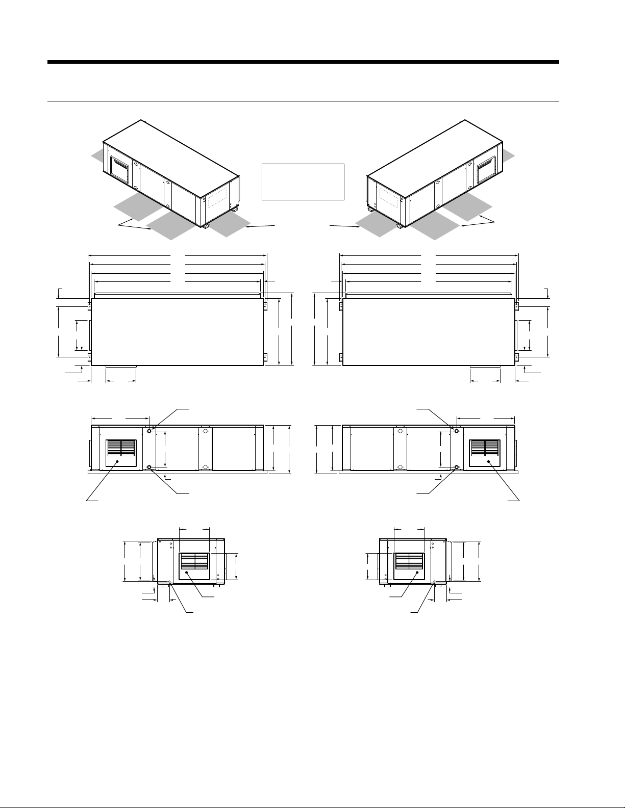
Horizontal Dimensions
7-10 Tons
2’ SECONDARY
SERVICE ACCESS
4.1
26.2
15.6
7.6
7.6 15.6
RIGHT RETURN
BP BP
Legend
AP = Alternate Service Panel
BP = Blower Service Panel
CP = Control Access Panel
CMP = Compressor Service Panel
CMP
2’ PRIMARY
SERVICE ACCESS
TOP VIEW
37.3
37.3
34.5
SIDE VIEW
29.929.9
CMP
92.5
90.0
89.0
85.9 1.6
WATER OUT
LEFT RETURN
34.5
CPCP
WATER OUT
92.5
90.0
89.0
85.91.6
CMP
CMP
2’ SECONDARY
SERVICE ACCESS
29.929.9
15.6
4.1
26.2
7.6
7.615.6
SIDE DISCHARGE
OPTION
21.0
20.1
2.9
6.1
18.6
3.4
WATER IN
15.62
DRAIN CONNECTION
13.5
END DISCHARGE
OPTION
23.5
24.5
END VIEW
24.5
23.5
END DISCHARGE
OPTION
DRAIN CONNECTION
13.5
WATER IN
15.62
18.6
3.4
SIDE DISCHARGE
OPTION
21.0
20.1
2.9
6.1
REV 4/28/08
8
Page 8
ENVISION 7-25 TONS INSTALLATION MANUAL
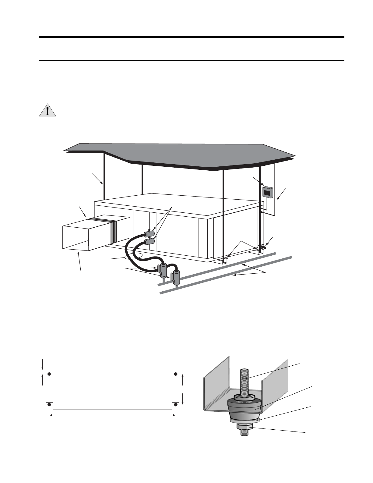
Installing Horizontal Units
Mounting Horizontal Units
Units are available with side or end discharge in left-hand or right-hand return air configurations. Horizontal units are
normally suspended from a ceiling by four 1/2 in. diameter threaded rods. The rods are usually attached to the unit corners
by the bottom panel mounting channel and the mounting grommets furnished with each unit.
CAUTION: Do not use rods smaller than 1/2 in. diameter since they may not be strong enough to support the
unit. The rods must be securely anchored to the ceiling (the units are approximately 800 lbs.).
Figure 1: Typical Horizontal Application
1/2”
Threaded Rods
(4)
Power
Disconnect
Low
Voltage
Flexible Duct
Collar
Hose Kits
Ball Valves
Insulate supply
plenum and use at
least a 90° elbow
to reduce noise
P/T Plugs
Isolation
Grommets
(Included)
Condensate
Drain
Connection
Water Loop
Layout the threaded rods per the dimensions in Figure 2. Assemble the hangers to the unit as shown in Figure 3. Securely
tighten the brackets to the unit. When attaching the hanger rods to the bracket, a double nut is recommended since
vibration could loosen a single nut. The unit should be pitched approximately 1/2 in. towards the drain in both directions, to
facilitate condensate removal.
Figure 3: Mounting HardwareFigure 2: Mounting Rod Layout
1/2 in. Threaded Rod
To p V i e w
(not included)
90.5
26.244.13
Isolator
Washer
(not included)
Hex Nuts
(not included)
9
Vibration
Page 9
ENVISION 7-25 TONS INSTALLATION MANUAL
Installing Horizontal Units cont.
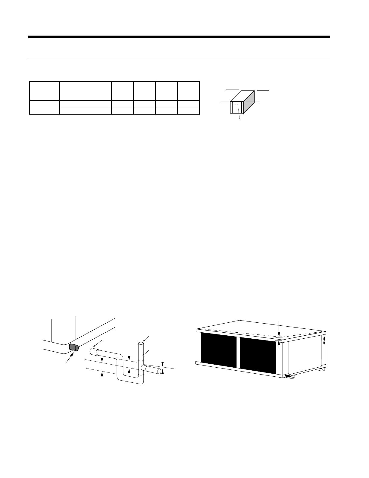
Horizontal Unit Corner Weight Distribution
ABCD
Front Front Back Back
Model Return / Discharge Left Right Right Left
080 - 120
Approximate
Left / Side or End 30% 26% 22% 22%
Right / Side or End 26% 30% 22% 22%
D
A
Controls
C
B
Duct System
An air outlet collar is provided on vertical top flow units and all horizontal units to facilitate a duct connection. A flexible
connector is recommended for discharge and return air duct connections on metal duct systems. Uninsulated duct should
be insulated with a minimum of 1-inch duct insulation. Application of the unit to uninsulated ductwork in an unconditioned
space is not recommended as the unit’s performance will be adversely affected.
If the unit is connected to existing ductwork, check the duct system to ensure that it has the capacity to accommodate the
air required for the unit application. If the duct is too small, as in the replacement of heating only systems, larger ductwork
should be installed. All existing ductwork should be checked for leaks and repaired if necessary.
The duct system should be sized to handle the design airflow quietly and efficiently. To maximize sound attenuation of the
unit blower, the supply and return plenums should include an internal duct liner of fiberglass or constructed of ductboard
for the first few feet. On systems employing a sheet metal duct system, canvas connectors should be used between the unit
and the ductwork. If air noise or excessive airflow is a problem, the blower speed can be changed.
Water Piping
The proper water flow must be provided to each unit whenever the unit operates. To assure proper flow, use pressure/temperature ports to determine the flow rate. These ports should be located at the supply and return water connections on the
unit. The proper flow rate cannot be accurately set without measuring the water pressure drop through the refrigerant-towater heat exchanger.
All source water connections on commercial units are fittings that accept a male pipe thread (MPT). Insert the connectors
by hand, then tighten the fitting with a wrench to provide a leakproof joint. When connecting to an open loop (groundwater) system, thread any copper MPT fitting into the connector and tighten in the same manner as described above.
Figure 5: Unit Pitch for DrainFigure 4: Suggested Layout of Condensate
1/2'' Pitch
Vent (if needed)
3/4 in. PVC
1/8 in. per foot
3/4 in. PVC tube stub
3/4 in. PVC
Coupling
1.5 in.
1.5 in.
10
Page 10
ENVISION 7-25 TONS INSTALLATION MANUAL
Installing Vertical Units
Mounting Vertical Units
Units are available with top/side discharge, left-hand or right-hand return air configurations. Vertical units are assembled on
rails which facilitate moving and placement of the units. It is not necessary to anchor the unit to the floor.
Duct System
A supply air duct flange is provided for field installation to facilitate the secure duct connection at the job site. A flexible
connector is recommended for discharge and return air duct connections on metal duct systems to prevent vibration
transmission. It is recommended that all ductwork be insulated with a minimum of 1/2-inch coated insulation. Installation of
the units with uninsulated ductwork in an unconditioned space is not recommended, as the system’s performance will be
adversely affected.
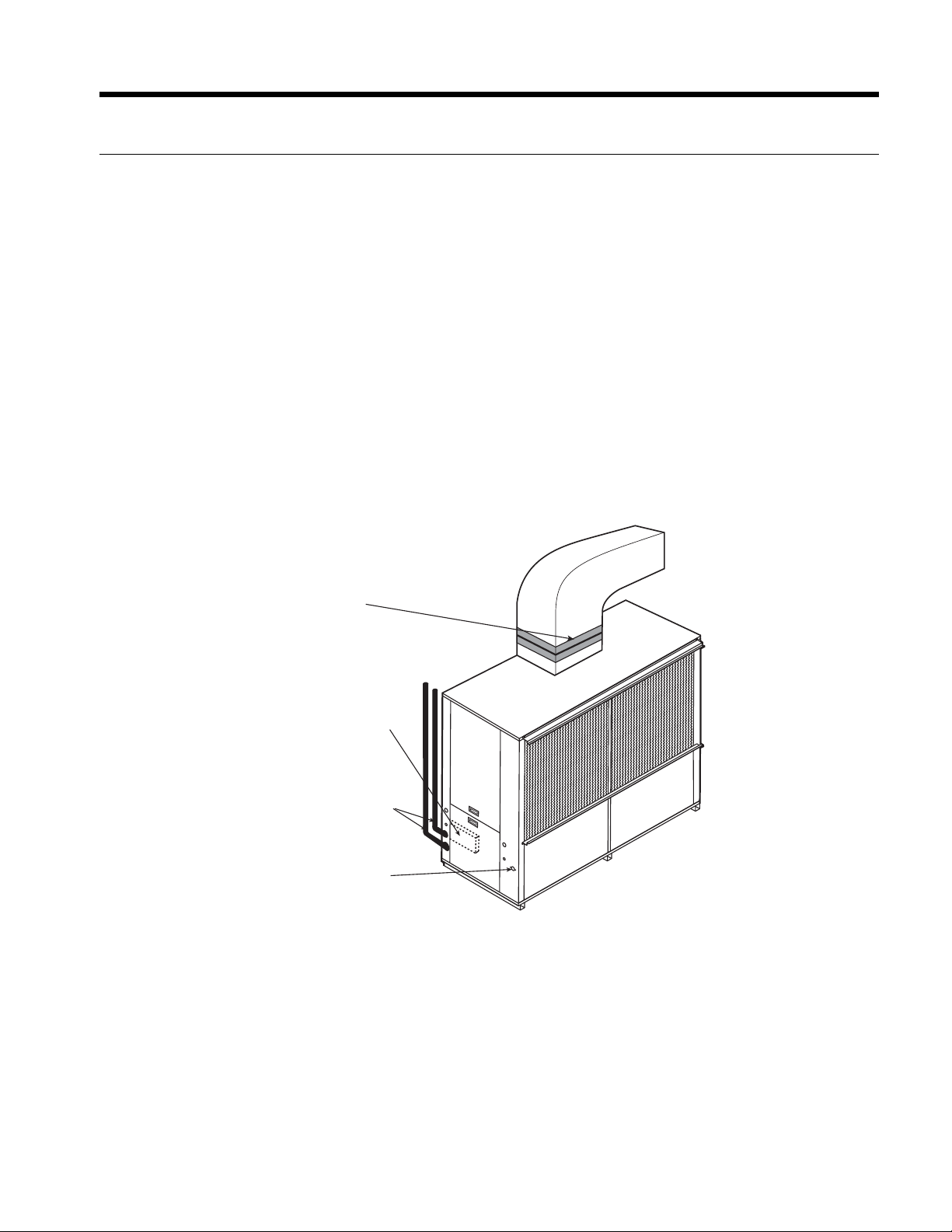
Condensate Drain
In vertical units, the internal condensate drain assembly consists of a flexible drain tube which is attached to the drain pan
and a 3/4-inch (7-10 tons) and 1-inch (13-25 tons) female pipe thread. An external water trap is not required as the drain
tube serves as a trapping loop. The field-installed piping and unit connection must be properly installed and sealed to
prevent water leakage.
Figure 6: Typical Vertical Application
Flexible duct
Collar
Control Box
Water Supply
and Return
Connections
Condensate
Drain
A
C
C
E
S
P
S
A
N
E
L
ACCESS
PAN EL
ACCESS
PANEL
11
Page 11
ENVISION 7-25 TONS INSTALLATION MANUAL
Water Quality
Water Quality Guidelines
In ground water situations where scaling could be heavy or where biological growth such as iron bacteria will be present,
a closed loop system is recommended. The heat exchanger coils in ground water systems may, over a period of time, lose
heat exchange capabilities due to a buildup of mineral deposits inside. These can be cleaned, but only by a qualified service
mechanic, as special solutions and pumping equipment are required. Hot water generator coils can likewise become scaled
and possibly plugged. In areas with extremely hard water, the owner should be informed that the heat exchanger may
require occasional flushing.
Units with cupronickel heat exchangers are recommended for open loop applications due to the increased resistance to
build-up and corrosion, along with reduced wear caused by acid cleaning.
Material Copper 90/10 Cupronickel 316 Stainless Steel
pH Acidity/Alkalinity
Scaling
Corrosion
Iron Fouling
(Biological Growth)
Erosion
NOTES: Grains = ppm divided by 17
mg/L is equivalent to ppm
Calcium and
Magnesium Carbonate
Hydrogen Sulfide
Chlorides Less than 20 ppm Less than 125 ppm Less than 300 ppm
Carbon Dioxide Less than 50 ppm 10 - 50 ppm 10 - 50 ppm
Ammonia Less than 2 ppm Less than 2 ppm Less than 20 ppm
Ammonia Chloride Less than 0.5 ppm Less than 0.5 ppm Less than 0.5 ppm
Ammonia Nitrate Less than 0.5 ppm Less than 0.5 ppm Less than 0.5 ppm
Ammonia Hydroxide Less than 0.5 ppm Less than 0.5 ppm Less than 0.5 ppm
Ammonia Sulfate Less than 0.5 ppm Less than 0.5 ppm Less than 0.5 ppm
Total Dissolved Solids (TDS) Less than 1000 ppm 1000 - 1500 ppm 1000 - 1500 ppm
LSI Index +0.5 to -0.5 +0.5 to -0.5 +0.5 to -0.5
Iron, FE
Bacterial Iron Potential
Iron Oxide
Suspended Solids
Threshold Velocity
(Fresh Water)
Less than 0.5 ppm (rotten egg
Sulfates Less than 125 ppm Less than 125 ppm Less than 200 ppm
Chlorine Less than 0.5 ppm Less than 0.5 ppm Less than 0.5 ppm
2
+ (Ferrous)
smell appears at 0.5 ppm)
Less than 1 ppm, above this
level deposition will occur
Less than 10 ppm and filtered
for max. of 600 mic
7 - 9 7 - 9 7 - 9
(Total Hardness)
less than 350 ppm
< 0.2 ppm < 0.2 ppm < 0.2 ppm
ron size
< 6 ft/sec < 6 ft/sec < 6 ft/sec
(Total Hardness)
less than 350 ppm
10 - 50 ppm Less than 1 ppm
Less than 1 ppm, above this
level deposition will occur
Less than 10 ppm and filtered
for max. of 600 micron size
Less than 1 ppm, above this
level deposition will occur
Less than 10 ppm and filtered
for max. of 600 micron size
(Total Hardness)
less than 350 ppm
2/22/12
Water Connections
All supply and return water connections are female pipe thread of size specified in physical dimensions. Never use flexible
hoses smaller than separate water connections on the unit and limit hose length to 10 ft. per connection. Check carefully for
water leaks.
Interior Piping
All units are recommended to be connected to supply and return piping in a two-pipe reverse return configuration. A
reverse return system is inherently self-balancing and requires only trim balancing when multiple quantities of units with
different flow and pressure drop characteristics are connected to the same loop. A direct return system may also be made
to work acceptably, but proper water flow balance is more difficult to achieve and maintain.
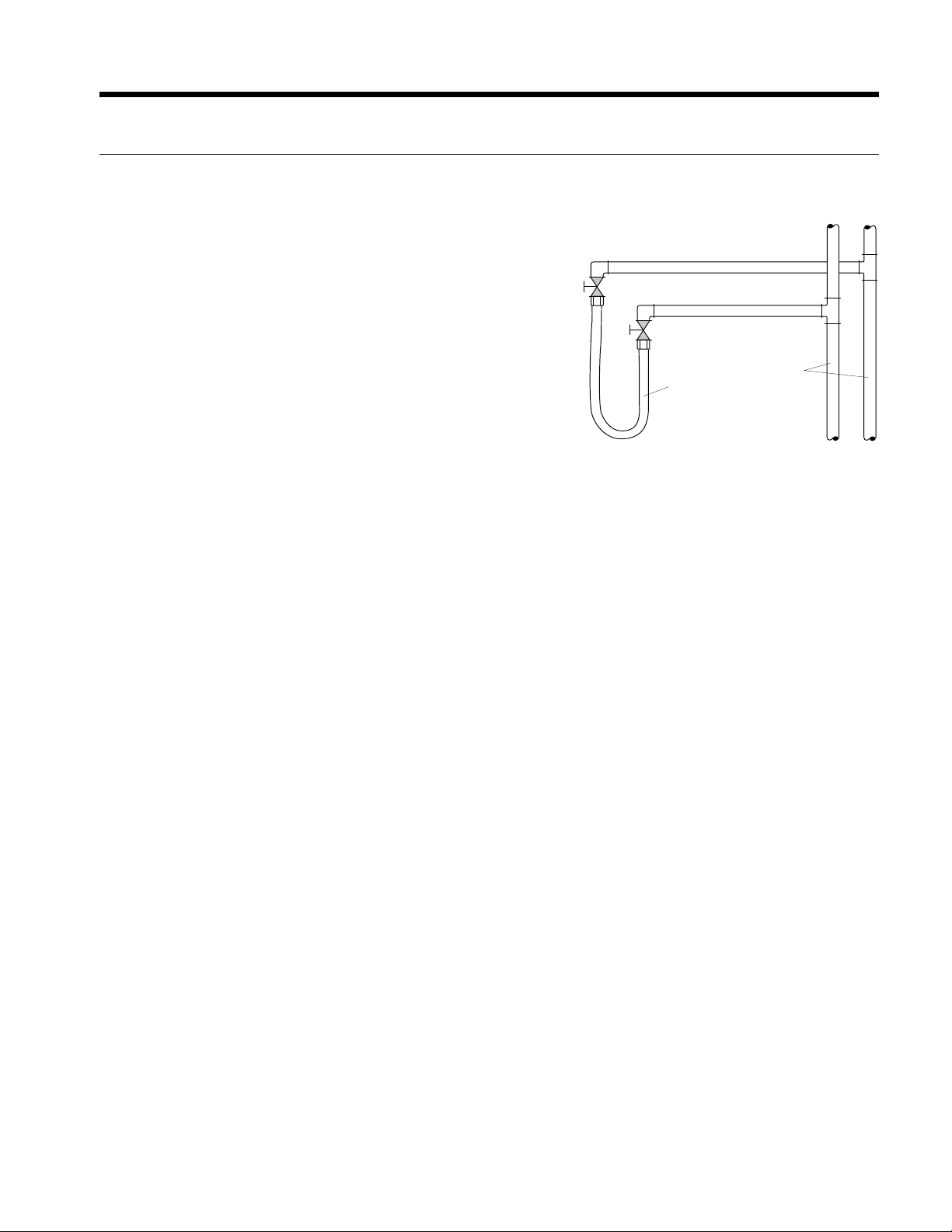
Supply and return runouts are usually connected to the unit by short lengths of high pressure flexible hose which are sound
attenuators for both unit operating noise and hydraulic pumping noise. One end of the hose should have a swivel fitting to
facilitate removal for service. Hard piping can also be connected directly to the unit although it is not recommended since
no vibration or noise attenuation can be accomplished. The hard piping must have unions to facilitate unit removal (see
figure 1 & 6) for typical application).
Some flexible hose threaded fittings are supplied with sealant compound. If not, apply Teflon tape to assure a tight seal.
Supply and return shutoff valves are required at each unit. The return shutoff valve can be used for balancing and should be
adjusted for proper flow required, or a manual or automatic flow control device should be on the leaving water hose assembly.
No unit should be connected to the supply and return piping until the water system has been cleaned and flushed
completely. After the cleaning and flushing has taken place, the initial connection should have all valves wide open in
preparation for water system filling.
12
Page 12
System Cleaning and Flushing
ENVISION 7-25 TONS INSTALLATION MANUAL
Cleaning and Flushing
Prior to start up of any heat pump, the water circulating system must be
cleaned and flushed of all dirt and debris.
If the system is equipped with water shutoff valves, the supply and
return runouts must be connected together at each unit location (This
will prevent the introduction of dirt into the unit, see Figure 7). The
system should be filled at the water make-up connection with all air
vents open. After filling, vents should be closed.
The contractor should start the main circulator with the pressure
reducing valve makeup open. Vents should be checked in sequence
to bleed off any trapped air and to verify circulation through all
components of the system.
As water circulates through the system, the contractor should check
and repair any leaks found in the piping system. Drain(s) at the lowest
point(s) in the system should be opened for initial flush and blowdown, making sure water fill valves are set at the same
rate. Check the pressure gauge at the pump suction and manually adjust the make-up water valve to hold the same
positive pressure both before and after opening the drain valves. Flushing should continue for at least two hours, or longer
if required, until drain water is clean and clear.
The supplemental heater and/or circulator pump, if used, should be shut off. All drains and vents should be opened to
completely drain the system. Short-circuited supply and return runouts should now be connected to the unit supply and
return connections.
Figure 7: Flushing with Water
Shutoff Valve Equipped Systems
Return Runout
Supply Runout
Mains
Rubber Hose
Runouts Initially
Connected Together
Refill the system with clean water. Test the system water for acidity and treat as required to leave the water slightly alkaline
(pH 7.5 to 8.5). The specified percentage of antifreeze may also be added at this time. Use commercial grade antifreeze
designed for HVAC systems only. Environol™ brand antifreeze is recommended..
Once the system has been filled with clean water and antifreeze (if used), precautions should be taken to protect the
system from dirty water conditions. Dirty water will result in system-wide degradation of performance, and solids may clog
valves, strainers, flow regulators, etc. Additionally, the heat exchanger may become clogged which reduces compressor
service life and can cause premature unit failure.
In boiler/tower application, set the loop control panel set points to desired temperatures. Supply power to all motors
and start the circulating pumps. After full flow has been established through all components including the heat rejector
(regardless of season), air vented and loop temperatures stabilized, each of the units will be ready for check, test and start
up and for air and water balancing.
Ground Source Loop System Checkout
Once piping is completed between the unit pumping system and ground loop, final purging and charging of the loop is
needed. A high pressure pump is needed to achieve adequate flow velocity in the loop to purge air and dirt particles from
the loop itself. Antifreeze solution is used in most areas to prevent freezing. Flush the system adequately to remove as
much air as possible; then pressurize the loop to a static pressure of 40-50 PSI (summer) or 50-75 PSI (winter). This is
normally adequate for good system operation. Loop static pressure may decrease soon after initial installation, due to pipe
expansion and loop temperature change. Running the unit for at least 30 minutes after the system has been completely
purged of air will allow for the “break-in” period. It may be necessary to adjust static loop pressure (by adding water) after
the unit has run for the first time. Loop static pressure will also fluctuate with the seasons. Pressures will be higher in the
winter months than during the cooling season. This fluctuation is normal and should be considered when charging the
system initially.
Ensure the pump provides adequate flow through the unit by checking pressure drop across the heat exchanger.
Usually 2.25-3.0 GPM of flow per ton of cooling capacity is recommended in earth loop applications.
13
Page 13

ENVISION 7-25 TONS INSTALLATION MANUAL
Electrical Connections
General
Be sure the available power is the same voltage and phase as that shown on the unit serial plate. Line and low voltage
wiring must be done in accordance with local codes or the National Electric Code.
Unit Power Connection
Line voltage connection is made by connecting the incoming line voltage wires to the terminal block as shown on the unit’s
wiring diagram attached to the inside front panel. Consult the Unit Electrical Data below for correct fuse size.
208 Volt Operation
NOTE: All 208-230 volt units are factory wired for 230 volt operation. For 208 volt operation, the red and the blue
transformer wires must be switched between terminal strip PS and contactor RB.
14
Page 14

Electrical Data
ENVISION 7-25 TONS INSTALLATION MANUAL
Model
Horizontal
080 460/60/3 414/506 9.0 5.8 38.0 2.4 1.5 13.9 15.4 20.0
080** 460/60/3 414/506 9.0 5.8 38.0 3.1 2.0 14.6 16.1 20.0
095 460/60/3 414/506 9.5 6.1 41.0 3.1 2.0 15.3 16.8 20.0
095** 460/60/3 414/506 9.5 6.1 41.0 4.3 3.0 16.5 18.0 20.0
120 460/60/3 414/506 12.1 7.7 52.0 4.3 3.0 19.8 21.7 25.0
Vertical
080 460/60/3 414/506 9.0 5.8 38.0 1.8 1.0 13.3 14.8 20.0
080** 460/60/3 414/506 9.0 5.8 38.0 2.4 1.5 13.9 15.4 20.0
095 460/60/3 414/506 9.5 6.1 41.0 2.4 1.5 14.6 16.1 20.0
095** 460/60/3 414/506 9.5 6.1 41.0 3.1 2.0 15.3 16.8 20.0
120 460/60/3 414/506 12.1 7.7 52.0 3.1 2.0 18.6 20.5 25.0
120** 460/60/3 414/506 12.1 7.7 52.0 4.3 3.0 19.8 21.7 25.0
160 460/60/3 414/506 16.5 10.6 75.0 1.8 1.0 24.8 54.0 35.0
160** 460/60/3 414/506 16.5 10.6 75.0 2.4 1.5 26.0 28.7 35.0
180 460/60/3 414/506 17.5 11.2 75.0 2.4 1.5 27.2 30.0 40.0
180** 460/60/3 414/506 17.5 11.2 75.0 3.1 2.0 28.6 31.4 40.0
240 460/60/3 414/506 26.0 16.6 114.0 3.1 2.0 39.5 43.6 60.0
240** 460/60/3 414/506 26.0 16.6 114.0 4.3 3.0 41.9 46.0 60.0
300 460/60/3 414/506 28.0 17.9 125.0 4.3 3.0 44.4 48.9 60.0
*Ratings per each compressor - unit supplied with two 9/10/07
**With optional motor
***Ratings per each blower motor - Vertical models 160-300 supplied with two.
Rated Voltage
Voltage Min/Max
208-230/60/3 187/253 16.3 10.4 88.0 4.8 1.5 25.7 28.3 35.0
575/60/3 518/632 5.9 3.8 36.5 1.9 1.5 9.5 10.4 10.0
208-230/60/3 187/253 16.3 10.4 88.0 6.2 2.0 27.1 29.7 40.0
575/60/3 518/632 5.9 3.8 36.5 2.5 2.0 10.1 11.0 10.0
208-230/60/3 187/253 21.2 13.6 83.1 6.2 2.0 33.3 36.7 50.0
575/60/3 518/632 7.8 5.0 34.0 2.5 2.0 12.5 13.7 15.0
208-230/60/3 187/253 21.2 13.6 83.1 9.2 3.0 36.3 39.7 50.0
575/60/3 518/632 7.8 5.0 34.0 3.4 3.0 13.4 14.6 15.0
208-230/60/3 187/253 24.9 15.9 110.0 9.2 3.0 41.1 45.1 60.0
575/60/3 518/632 8.9 5.7 38.9 3.4 3.0 14.8 16.2 20.0
208-230/60/3 187/253 16.3 10.4 88.0 3.6 1.0 24.5 27.1 35.0
575/60/3 518/632 5.9 3.8 36.5 1.5 1.0 9.0 9.9 10.0
208-230/60/3 187/253 16.3 10.4 88.0 4.8 1.5 25.7 28.3 35.0
575/60/3 518/632 5.9 3.8 36.5 1.9 1.5 9.5 10.4 10.0
208-230/60/3 187/253 21.2 13.6 83.1 4.8 1.5 31.9 35.3 45.0
575/60/3 518/632 7.8 5.0 34.0 1.9 1.5 11.9 13.1 15.0
208-230/60/3 187/253 21.2 13.6 83.1 6.2 2.0 33.3 36.7 50.0
575/60/3 518/632 7.8 5.0 34.0 2.5 2.0 12.5 13.7 15.0
208-230/60/3 187/253 24.9 15.9 110.0 6.2 2.0 38.1 42.1 50.0
575/60/3 518/632 8.9 5.7 38.9 2.5 2.0 13.9 15.3 20.0
208-230/60/3 187/253 24.9 15.9 110.0 9.2 3.0 41.1 45.1 60.0
575/60/3 518/632 8.9 5.7 38.9 3.4 3.0 14.8 16.2 20.0
208-230/60/3 187/253 35.0 22.4 149.0 3.6 1.0 52.0 57.6 80.0
575/60/3 518/632 12.0 7.7 54.0 1.5 1.0 18.4 20.3 25.0
208-230/60/3 187/253 35.0 22.4
575/60/3 518/632 12.0 7.7 54.0 1.9 1.5 19.2 21.1 25.0
208-230/60/3 187/253 36.2 23.2 164.0 4.8 1.5 56.0 61.8 80.0
575/60/3 518/632 12.3 7.9 54.0 1.9 1.5 19.6 21.6 25.0
208-230/60/3 187/253 36.2 23.2 164.0 6.2 2.0 58.8 64.6 80.0
575/60/3 518/632 12.3 7.9 54.0 2.5 2.0 20.8 22.8 30.0
208-230/60/3 187/253 47.0 30.1 225.0 6.2 2.0 72.6 80.1 110.0
575/60/3 518/632 19.0 12.2 80.0 2.5 2.0 29.3 32.4 40.0
208-230/60/3 187/253 47.0 30.1 225.0 9.2 3.0 78.6 86.1 110.0
575/60/3 518/632 19.0 12.2 80.0 3.4 3.0 31.1 34.2 45.0
208-230/60/3 187/253 52.0 33.3 239.0 9.2 3.0 85.0 93.3 125.0
575/60/3 518/632 20.0 12.8 80.0 3.4 3.0 32.4 35.6 45.0
Compressor*
MCC RLA LRA FLA*** *** FLA Amp HACR
149.0 4.8 1.5 54.4 60.0 80.0
Blower Blower Total Min Max
Motor HP Unit Circ Fuse/
HACR circuit breaker in USA only
All fuses Class RK-5
15
Page 15

ENVISION 7-25 TONS INSTALLATION MANUAL
NLV080 - Blower Performance Data
Belt Drive
Airflow in CFM with dry coil and clean air filter.
Rated CFM
MTR/SHEAVE 2.0 2.0 2.0 2.0 1.0 1.0 1.0 1.0 1.0 1.0 1.0 5.0 5.0 5.0 5.0 5.0
BHP 0.29 0.33 0.38 0.37 0.45 0.47 0.50 0.54 0.58 0.64 0.69 0.71 0.73 0.84 0.95 1.05
2200
RPM 437 478 518 539 586 617 647 677 707 736 765 775 809 843 876 909
TURNS OPEN 4.0 3.0 2.0 1.5 5.0 4.5 4.0 3.5 3.0 2.5 2.0 3.5 3.0 2.5 2.0 1.5
MTR/SHEAVE 2.0 2.0 2.0 1.0 1.0 1.0 1.0 1.0 1.0 1.0 5.0 5.0 5.0 5.0 5.0 5.0
BHP 0.38 0.44 0.43 0.52 0.56 0.59 0.63 0.68 0.73 0.78 0.81 0.83 0.94 1.05 1.13 1.20
2400
RPM 477 517 538 585 615 645 675 704 734 763 774 807 841 874 907 940
TURNS OPEN 3.0 2.0 1.5 5.0 4.5 4.0 3.5 3.0 2.5 2.0 3.5 3.0 2.5 2.0 1.5 1.0
MTR/SHEAVE 2.0 2.0 1.0 1.0 1.0 1.0 1.0 1.0 1.0 5.0 5.0 5.0 5.0 5.0 5.0
BHP 0.49 0.50 0.59 0.63 0.67 0.72 0.77 0.83 0.89 0.91 0.94 1.05 1.17 1.24 1.32
2600
RPM 516 537 584 614 643 673 702 732 761 772 806 839 871 905 938
TURNS OPEN 2.0 1.5 5.0 4.5 4.0 3.5 3.0 2.5 2.0 3.5 3.0 2.5 2.0 1.5 1.0
MTR/SHEAVE 2.0 1.0 1.0 1.0 1.0 1.0 1.0 1.0 5.05.05.05.05.05.0
BHP 0.56 0.66 0.71 0.75 0.81 0.86 0.92 0.99 1.02 1.05 1.17 1.29 1.37 1.44
2800
RPM 536 582 612 642 671 700 729 758 770 804 837 869 903 936
TURNS OPEN 1.5 5.0 4.5 4.0 3.5 3.0 2.5 2.0 3.5 3.0 2.5 2.0 1.5 1.0
MTR/SHEAVE 1.0 1.0 1.0 1.0 1.0 1.0 1.0 5.0 5.0 5.0 5.0 5.0 5.0
BHP 0.72 0.78 0.83 0.89 0.95 1.02 1.09 1.12 1.16 1.29 1.41 1.49 1.57
3000
RPM 581 611 640 669 698 727 756 768 802 835 867 900 933
TURNS OPEN 5.0 4.5 4.0 3.5 3.0 2.5 2.0 3.5 3.0 2.5 2.0 1.5 1.0
MTR/SHEAVE 1.0 1.0 1.0 1.0 1.0 1.0 5.0 5.0 5.0 5.0 5.0 5.0
BHP 0.83 0.90 0.97 1.03 1.11 1.18 1.14 1.27 1.40 1.53 1.61 1.70
3200
RPM 610 639 668 697 726 754 767 800 833 865 898 930
TURNS OPEN 4.5 4.0 3.5 3.0 2.5 2.0 3.5 3.0 2.5 2.0 1.5 1.0
MTR/SHEAVE 1.0 1.0 1.0 1.0 5.0 5.0 5.0 5.0 5.0 5.0 5.0
BHP 0.97
3400
RPM 637 666 695 725 731 765 798 830 862 895 927
TURNS OPEN 4.0 3.5 3.0 2.5 4.0 3.5 3.0 2.5 2.0 1.5 1.0
Bold Face Requires 1.5 HP Motor
A=Std Static/Std Mtr;B=Low Static/Std. Mtr;C=High Static/Std. Mtr;D=Std Static/Large Mtr;E=High Static/Large Mtr
Units factory shipped with standard static sheave and drive at 3 turns open (2600 cfm @ 0.6 in. ESP). Other speeds require field selection.
ISO/AHRI rating point with standard static sheave and drive at 3 turns open (2600 cfm @ 0.6 in. ESP). Other speeds require field selection.
For applications requiring higher static pressures, contact your local representative.
Performance data does not include drive losses and is based on sea level conditions.
Do not operate in gray region. "na" = information not available at time of printing.
All airflow is rated at lowest Voltage if unit is dual Voltage rated, i.e. 208V for 208-230V units.
For wet coil performance first calculate the face velocity of the air coil (Face Velocity [fpm] = Airflow [cfm] / Face Area [sq ft]).
Then for velocities of 200 fpm reduce the static capability by 0.03 in. wg, 300 fpm by 0.08 in. wg, and 400 fpm by 0.12in. wg.
0.0 0.1 0.2 0.3 0.4 0.5 0.6 0.7 0.8 0.9 1.0 1.1 1.2 1.3 1.4 1.5
B
1.04 1.11 1.19 1.23 1.30 1.37 1.51 1.64 1.73 1.82
External Static Pressure (in. w.g.)
A
E
07/25/07
16
Page 16

ENVISION 7-25 TONS INSTALLATION MANUAL
NLV095 - Blower Performance Data
Belt Drive
Airflow in CFM with dry coil and clean air filter.
External Static Pressure (in. w.g.)
Rated CFM
MTR/SHEAVE 1.0 1.0 1.0 1.0 1.0 1.0 1.0 1.0 4.0 4.0
BHP 0.61 0.64 0.66 0.68 0.76 0.81 0.87 0.89 0.94 1.05
2600
RPM 581 601 621 663 703 739 774 784 827 867
TURNS OPEN 5.0 4.5 4.0 3.0 2.0 1.5 1.0 0.0 2.0 1.0
MTR/SHEAVE 1.0 1.0 1.0 1.0 1.0 1.0 1.0 1.0 4.0 4.0 4.0
BHP 0.65 0.66 0.68 0.75 0.86 0.87 0.88 1.02 1.05 1.14 1.23
2800
RPM 580 600 621 662 701 722 742 782 805 855 905
TURNS OPEN 5.0 4.5 4.0 3.0 2.0 1.5 1.0 0.0 2.5 1.5 0.0
MTR/SHEAVE 1.0 1.0 1.0 1.0 1.0 1.0 1.0 1.0 3.0 3.0 3.0 3.0 3.0 5.0 5.0
BHP 0.72 0.73 0.74 0.84 0.96 0.98 0.99 1.13 1.14 1.17 1.23 1.36 1.48 1.59 1.69
3000
RPM 579 600 620 660 700 721 741 780 797 813 845 890 940 960 991
TURNS OPEN 5.0 4.5 4.0 3.0 2.0 1.5 1.0 0.0 3.0 2.5 2.0 1.0 0.0 3.0 2.5
MTR/SHEAVE 1.0 1.0 1.0 1.0 1.0 1.0 1.0 1.0 3.0 3.0 3.0 3.0 3.0 5.0 5.0 5.0
BHP 0.79 0.80 0.82 0.93 1.06 1.08 1.10 1.25 1.26 1.31 1.36 1.49 1.62 1.67 1.85 2.03
3200
RPM 578 599 619 659 699 719 739 778 795 819 843 890 937 942 967 991
TURNS OPEN 5.0 4.5 4.0 3.0 2.0 1.5 1.0 0.0 3.0 2.5 2.0 1.0 0.0 3.0 2.5 2.0
MTR/SHEAVE 1.0 1.0 1.0 1.0 1.0 1.0 1.0 3.0 3.0 3.0 3.0 3.0 5.0 5.0 5.0 5.0
BHP 0.84 0.89 1.01 1.15 1.17 1.20 1.35 1.36 1.42 1.48 1.52 1.61 1.82 1.90 1.99 2.03
3400
RPM 597 619 658 697 718 738 776 794 818 841 857 888 940 963 986 1034
TURNS OPEN 4.5 4.0 3.0 2.0 1.5 1.0 0.0 3.0 2.5 2.0 1.5 1.0 3.0 2.5 2.0 1.0
MTR/SHEAVE 1.0 1.0 1.0 1.0 1.0 1.0 3.0 3.0 3.0 3.0 3.0 5.0 5.0 5.0 5.0 5.0
BHP 0.97 1.09 1.23 1.26 1.29 1.45 1.47 1.53 1.60 1.67 1.74 1.95 2.05 2.14 2.19 2.41
3600
RPM 618 657 696 716 736 775 792 815 838 862 885 937 960 983 1031 1077
TURNS OPEN 4.0 3.0 2.0 1.5 1.0 0.0 3.0 2.5 2.0 1.5 1.0 3.0 2.5 2.0 1.0 0.0
MTR/SHEAVE 1.0 1.0 1.0 1.0 1.0 3.0 3.0 3.0 3.0 3.0 5.0 5.0 5.0 5.0 5.0
BHP 1.17 1.32 1.35 1.38 1.55
3800
RPM 656 695 715 735 773 790 814 837 860 883 935 958 981 1029 1074
TURNS OPEN 3.0 2.0 1.5 1.0 0.0 3.0 2.5 2.0 1.5 1.0 3.0 2.5 2.0 1.0 0.0
Bold Face Requires Larger 2 HP Motor
A=Std Static/Std Mtr;B=Low Static/Std. Mtr;C=High Static/Std. Mtr;D=Std Static/Large Mtr;E=High Static/Large Mtr
Units factory shipped with standard static sheave and drive at 2 turns open (2800 cfm @ 0.6 in. ESP). Other speeds require field selection.
ISO/AHRI rating point with standard static sheave and drive at 1 turns open (2800 cfm @ 0.7 in. ESP). Other speeds require field selection.
For applications requiring higher static pressures, contact your local representative.
Performance data does not include drive losses and is based on sea level conditions.
Do not operate in gray region. "na" = information not available at time of printing.
All airflow is rated at lowest Voltage if unit is dual Voltage rated, i.e. 208V for 208-230V units.
For wet coil performance first calculate the face velocity of the air coil (Face Velocity [fpm] = Airflow [cfm] / Face Area [sq ft]).
Then for velocities of 200 fpm reduce the static capability by 0.03 in. wg, 300 fpm by 0.08 in. wg, and 400 fpm by 0.12in. wg.
0.0 0.1 0.2 0.3 0.4 0.5 0.6 0.7 0.8 0.9 1.0 1.2 1.4 1.6 1.8 2.0
D
A
C
E
1.57 1.64 1.71 1.78 1.86 2.09 2.18 2.28 2.34 2.57
7/25/07
17
Page 17

ENVISION 7-25 TONS INSTALLATION MANUAL
NLV120 - Blower Performance Data
Belt Drive
Airflow in CFM with dry coil and clean air filter.
Rated CFM
MTR/SHEAVE 2.0 2.0 2.0 2.0 2.0 1.0 1.0 1.0 1.0 1.0 1.0 1.0 3.0 3.0 3.0
BHP 0.50 0.51 0.59 0.68 0.68 0.79 0.92 0.92 0.92 1.08 1.16 1.30 1.31 1.41 1.59
3200
RPM 418 438 480 521 541 582 623 644 665 705 732 787 826 867 932
TURNS OPEN 4.5 4.0 3.0 2.0 1.0 5.0 4.0 3.5 3.0 2.0 1.5 0.5 2.0 1.0 0.0
MTR/SHEAVE 2.0 2.0 2.0 2.0 1.0 1.0 1.0 1.0 1.0 1.0 1.0 3.0 3.0 3.0
BHP 0.58 0.67 0.77 0.78 0.90 1.04 1.05 1.07 1.16 1.26 1.28 1.37 1.47 1.65
3400
RPM 438 480 520 541 582 622 643 664 694 724 746 795 843 888
TURNS OPEN 4.0 3.0 2.0 1.0 5.0 4.0 3.5 3.0 2.5 1.5 1.0 3.0 1.5 0.5
MTR/SHEAVE 2.0 2.0 2.0 1.0 1.0 1.0 1.0 1.0 1.0 1.0 3.0 3.0 3.0 3.0
BHP 0.74 0.86 0.88 1.00 1.02 1.17 1.20 1.22 1.24 1.44 1.47 1.52 1.82 1.90
3600
RPM 479 519 540 581 602 643 663 684 704 745 765 806 866 906
TURNS OPEN 3.0 2.0 1.0 5.0 4.5 3.5 3.0 2.5 2.0 1.0 3.5 2.5 1.0 0.0
MTR/SHEAVE 2.0 2.0 1.0 1.0 1.0 1.0 1.0 1.0 1.0 3.0 3.0 3.0 3.0
BHP 0.94 0.96 1.10 1.15 1.24 1.32 1.35 1.38 1.41 1.62 1.66 1.91 2.06
3800
RPM 519 539 581 622 642 662 683 704 723 764 784 823 884
TURNS OPEN 2.0 1.0 5.0 4.0 3.5 3.0 2.5 2.0 1.5 3.5 3.0 2.0 0.5
MTR/SHEAVE 2.0 1.0 1.0 1.0 1.0 1.0 1.0 1.0 1.0 3.0 3.0 3.0 3.0 5.0 5.0 5.0
BHP 1.04 1.20 1.26 1.35 1.44 1.47 1.51 1.55 1.58 1.81 1.86 1.96 2.17 2.25 2.39 2.66
4000
RPM 539 580 621 641 661 682 703 724 744 783 803 843 893 933 970 1017
TURNS OPEN 1.0 5.0 4.0 3.5 3.0 2.5 2.0 1.5 1.0 3.0 2.5 1.5 0.0 3.5 2.5 1.5
MTR/SHEAVE 1.0 1.0 1.0 1.0 1.0 1.0 1.0 1.0 4.0 4.0 4.0 4.0 4.0 5.0 5.0 5.0
BHP 1.28 1.36 1.45 1.54 1.59 1.63 1.67 1.72 1.95 2.01 2.06 2.19 2.31 2.48 2.75 3.03
4200
RPM 580 620 641 661 682 702 722 742 782 802 822 863 902 944 991 1037
TURNS OPEN 5.0 4.0 3.5 3.0 2.5 2.0 1.5 1.0 3.0 2.5 2.0 1.0 0.0 3.0 2.0 1.0
MTR/SHEAVE 1.0 1.0 1.0 1.0 1.0
BHP 1.46 1.55 1.65 1.70 1.75 1.80 1.85 2.09 2.15 2.21 2.28 2.41 2.54 2.80 3.08
4400
RPM 620 640 660 681 701 722 742 781 801 821 841 881 919 965 1012
TURNS OPEN 4.0 3.5 3.0 2.5 2.0 1.5 1.0 3.0 2.5 2.0 1.5 0.5 3.5 2.5 1.5
Bold Face Requires Larger 3 HP Motor
A=Std Static/Std Mtr;B=Low Static/Std. Mtr;C=High Static/Std. Mtr;D=Std Static/Large Mtr;E=High Static/Large Mtr
Units factory shipped with standard static sheave and drive at 3 turns open (3600 cfm @ 0.6 in. ESP). Other speeds require field selection.
ISO/AHRI rating point with standard static sheave and drive at 1 turns open (3600 cfm @ 0.9 in. ESP). Other speeds require field selection.
For applications requiring higher static pressures, contact your local representative.
Performance data does not include drive losses and is based on sea level conditions.
Do not operate in gray region. "na" = information not available at time of printing.
All airflow is rated at lowest Voltage if unit is dual Voltage rated, i.e. 208V for 208-230V units.
For wet coil performance first calculate the face velocity of the air coil (Face Velocity [fpm] = Airflow [cfm] / Face Area [sq ft]).
Then for velocities of 200 fpm reduce the static capability by 0.03 in. wg, 300 fpm by 0.08 in. wg, and 400 fpm by 0.12 in. wg.
0.0 0.1 0.2 0.3 0.4 0.5 0.6 0.7 0.8 0.9 1.0 1.2 1.4 1.6 1.8 2.0
B
External Static Pressure (in. w.g.)
A
C
E
1.0 1.0 4.0 4.0 4.0 4.0 4.0 5.0 5.0 5.0
D
07/25/07
18
Page 18

ENVISION 7-25 TONS INSTALLATION MANUAL
NLV160 - Blower Performance Data
Belt Drive
Airflow in CFM with dry coil and clean air filter.
Rated CFM
MTR/SHEAVE 2.0 2.0 2.0 2.0 1.0 1.0 1.0 1.0 1.0 1.0 1.0 5.0 5.0 5.0 5.0 5.0
BHP 0.29 0.33 0.38 0.37 0.45 0.47 0.50 0.54 0.58 0.64 0.69 0.71 0.73 0.84 0.95 1.05
4400
RPM 437 478 518 539 586 617 647 677 707 736 765 775 809 843 876 909
TURNS OPEN 4.0 3.0 2.0 1.5 5.0 4.5 4.0 3.5 3.0 2.5 2.0 3.5 3.0 2.5 2.0 1.5
MTR/SHEAVE 2.0 2.0 2.0 2.0 1.0 1.0 1.0 1.0 1.0 1.0 1.0 5.0 5.0 5.0 5.0 5.0
BHP 0.33 0.38 0.41 0.44 0.50 0.53 0.57 0.61 0.66 0.71 0.75 0.77 0.84 0.95 1.04 1.13
4600
RPM 457 498 528 562 601 631 661 691 720 750 770 791 825 858 892 925
TURNS OPEN 3.5 2.5 1.5 0.5 4.5 4.0 3.5 3.0 2.5 2.0 1.0 3.0 2.5 2.0 1.5 1.0
MTR/SHEAVE 2.0 2.0 2.0 1.0 1.0 1.0 1.0 1.0 1.0 1.0 5.0 5.0 5.0 5.0 5.0 5.0
BHP 0.38 0.44 0.43 0.52 0.56 0.59 0.63 0.68 0.73 0.78 0.81 0.83 0.94 1.05 1.13 1.20
4800
RPM 477 517 538 585 615 645 675 704 734 763 774 807 841 874 907 940
TURNS OPEN 3.0 2.0 1.5 5.0 4.5 4.0 3.5 3.0 2.5 2.0 3.5 3.0 2.5 2.0 1.5 1.0
MTR/SHEAVE 2.0 2.0 2.0 1.0 1.0 1.0 1.0 1.0 1.0 1.0 5.0 5.0 5.0 5.0 5.0 5.0
BHP 0.44 0.47 0.51 0.58 0.62 0.66 0.70 0.75 0.81 0.85 0.87 0.94 1.05 1.15 1.22 0.60
5000
RPM 497 527 561 599 629 659 688 718 747 768 790 823 856 889 923 470
TURNS OPEN 2.5 1.5 1.0 4.5 4.0 3.5 3.0 2.5 2.0 1.5 3.0 2.5 2.0 1.5 1.0 0.5
MTR/SHEAVE 2.0 2.0 1.0 1.0 1.0 1.0 1.0 1.0 1.0 5.0 5.0 5.0 5.0 5.0 5.0
BHP 0.49 0.50 0.59 0.63 0.67 0.72 0.77 0.83 0.89 0.91 0.94 1.05 1.17 1.24 1.32
5200
RPM 516 537 584 614 643 673 702 732 761 772 806 839 871 905 938
TURNS OPEN 2.0 1.5 5.0 4.5 4.0 3.5 3.0 2.5 2.0 3.5 3.0 2.5 2.0 1.5 1.0
MTR/SHEAVE 2.0 2.0 1.0 1.0 1.0 1.0 1.0 1.0 1.0 5.0 5.0 5.0 5.0 5.0 5.0
BHP 0.53 0.58 0.65 0.69 0.74 0.79 0.85 0.91 0.95 0.98 1.05 1.17 1.27 1.34 0.66
5400
RPM 526 560 598 628 657 686 716 745 766 788 821 854 887
TURNS OPEN 1.5 1.0 4.5 4.0 3.5 3.0 2.5 2.0 1.5 3.0 2.5 2.0 1.5 1.0 0.5
MTR/SHEAVE 2.0 1.0 1.0 1.0 1.0 1.0 1.0 1.0 5.0 5.0 5.0 5.0 5.0 5.0
BHP 0.56 0.66 0.71 0.75 0.81 0.86 0.92 0.99 1.02 1.05 1.17 1.29 1.37 1.44
5600
RPM 536 582 612 642 671 700 729 758 770 804 837 869 903 936
TURNS OPEN 1.5 5.0 4.5 4.0 3.5 3.0 2.5 2.0 3.5 3.0 2.5 2.0 1.5 1.0
Bold Face Requires Larger 1.5 HP Motor
A=Std Static/Std Mtr;B=Low Static/Std. Mtr;C=High Static/Std. Mtr;D=Std Static/Large Mtr;E=High Static/Large Mtr
Units factory shipped with standard static sheave and drive at 3 turns open (5000 cfm @ 0.6 in. ESP). Other speeds require field selection.
ISO/AHRI rating point with standard static sheave and drive at 2.0 turns open (5000 cfm @ 0.7 in. ESP). Other speeds require field selection.
For applications requiring higher static pressures, contact your local representative.
Performance data does not include drive losses and is based on sea level conditions.
Do not operate in gray region. "na" = information not available at time of printing.
All airflow is rated at lowest Voltage if unit is dual Voltage rated, i.e. 208V for 208-230V units.
For wet coil performance first calculate the face velocity of the air coil (Face Velocity [fpm] = Airflow [cfm] / Face Area [sq ft]).
Then for velocities of 200 fpm reduce the static capability by 0.03 in. wg, 300 fpm by 0.08 in. wg, and 400 fpm by 0.12 in. wg.
BHP is given for each blower. Multiply BHP x 2 for unit BHP.
0.0 0.1 0.2 0.3 0.4 0.5 0.6 0.7 0.8 0.9 1.0 1.1 1.2 1.3 1.4 1.5
B
External Static Pressure (in. w.g.)
A
E
920 469
7/25/07
19
Page 19

ENVISION 7-25 TONS INSTALLATION MANUAL
NLV180 - Blower Performance Data
Belt Drive
Airflow in CFM with dry coil and clean air filter.
Rated CFM
MTR/SHEAVE 1.0 1.0 1.0 1.0 1.0 1.0 1.0 1.0 4.0 4.0
BHP 0.61 0.64 0.66 0.68 0.76 0.81 0.87 0.89 0.94 1.05
5200
RPM 581 601 621 663 703 739 774 784 827 867
TURNS OPEN 5.0 4.5 4.0 3.0 2.0 1.5 1.0 0.5 2.0 1.0
MTR/SHEAVE 1.0 1.0 1.0 1.0 1.0 1.0 1.0 1.0 4.0 4.0
BHP 0.64 0.66 0.71 0.77 0.82 0.85 0.94 0.97 1.04 1.14
5400
RPM 591 611 642 682 712 740 778 795 841 886
TURNS OPEN 4.5 4.0 3.5 2.5 1.5 1.0 0.5 0.0 1.5 0.5
MTR/SHEAVE 1.0 1.0 1.0 1.0 1.0 1.0 1.0 1.0 4.0 4.0 4.0
BHP 0.65 0.66 0.68 0.75 0.86 0.87 0.88 1.02 1.05 1.14 1.23
5600
RPM 580 600 621 662 701 722 742 782 805 855 905
TURNS OPEN 5.0 4.5 4.0 3.0 2.0 1.5 1.0 0.0 2.5 1.5 0.0
MTR/SHEAVE 1.0 1.0 1.0 1.0 1.0 1.0 1.0 1.0 3.0 3.0 3.0 3.0 5.0 5.0
BHP 0.69 0.70 0.76 0.86 0.92 0.93 1.01 1.08 1.11 1.19 1.30 0.74 0.80 0.85
5800
RPM 590 610 641 681 711 731 761 790 809 850 898 470 480 496
TURNS OPEN 4.5 4.0 3.5 2.5 1.5 1.0 0.5 0.0 3.0 2.5 2.0 1.0 3.0 2.5
MTR/SHEAVE 1.0 1.0 1.0 1.0 1.0 1.0 1.0 1.0 3.0 3.0 3.0 3.0 3.0 5.0 5.0
BHP 0.72 0.73 0.74 0.84 0.96 0.98 0.99 1.13 1.14 1.17 1.23 1.36 1.48 1.59 1.69
6000
RPM 579 600 620 660 700 721 741 780 797 813 845 890 940 960 991
TURNS OPEN 5.0 4.5 4.0 3.0 2.0 1.5 1.0 0.0 3.0 2.5 2.0 1.0 0.0 3.0 2.5
MTR/SHEAVE 1.0 1.0 1.0 1.0 1.0 1.0 1.0 1.0 3.0 3.0 3.0 3.0 5.0 5.0 5.0
BHP 0.76 0.77 0.84 0.95 1.02 1.04 1.12 1.20 1.23 1.27 1.36 1.49 1.58 1.72 1.86
6200
RPM 589 609 640 680 710 730 760 788 808 828 868 914 941 963 991
TURNS OPEN 4.5 4.0 3.5 2.5 1.5 1.0 0.5 0.0 2.5 2.0 1.5 0.5 3.5 2.5 2.0
MTR/SHEAVE 1.0 1.0 1.0 1.0 1.0 1.0 1.0 1.0 3.0 3.0 3.0 3.0 3.0 5.0 5.0 5.0
BHP 0.79 0.80 0.82 0.93 1.06 1.08 1.10 1.25 1.26 1.31 1.36 1.49 1.62 1.67 1.85 2.03
6400
RPM 578 599 619 659 699 719 739 778 795 819 843 890 937 942 967 991
TURNS OPEN 5.0 4.5 4.0 3.0 2.0 1.5
Bold Face Requires Larger 2.0 HP Motor
A=Std Static/Std Mtr;B=Low Static/Std. Mtr;C=High Static/Std. Mtr;D=Std Static/Large Mtr;E=High Static/Large Mtr
Units factory shipped with standard static sheave and drive at 3 turns open (5600 cfm @ 0.6 in. ESP). Other speeds require field selection.
ISO/AHRI rating point with standard static sheave and drive at 1.5 turns open (5600 cfm @ 0.7 in. ESP). Other speeds require field selection.
For applications requiring higher static pressures, contact your local representative.
Performance data does not include drive losses and is based on sea level conditions.
Do not operate in gray region. "na" = information not available at time of printing.
All airflow is rated at lowest Voltage if unit is dual Voltage rated, i.e. 208V for 208-230V units.
For wet coil performance first calculate the face velocity of the air coil (Face Velocity [fpm] = Airflow [cfm] / Face Area [sq ft]).
Then for velocities of 200 fpm reduce the static capability by 0.03 in. wg, 300 fpm by 0.08 in. wg, and 400 fpm by 0.12 in. wg.
BHP is given for each blower. Multiply BHP x 2 for unit BHP.
0.0 0.1 0.2 0.3 0.4 0.5 0.6 0.7 0.8 0.9 1.0 1.2 1.4 1.6 1.8 2.0
External Static Pressure (in. w.g.)
A
D
C
1.0 0.0 3.0 2.5 2.0 1.0 0.0 3.0 2.5 2.0
E
7/25/07
20
Page 20

ENVISION 7-25 TONS INSTALLATION MANUAL
NLV240 - Blower Performance Data
Belt Drive
Airflow in CFM with dry coil and clean air filter.
Rated CFM
MTR/SHEAVE 2.0 2.0 2.0 2.0 2.0 1.0 1.0 1.0 1.0 1.0 1.0 1.0 3.0 3.0 3.0
BHP 0.50 0.51 0.59 0.68 0.68 0.79 0.92 0.92 0.92 1.08 1.16 1.30 1.31 1.41 1.59
6400
RPM 418 438 480 521 541 582 623 644 665 705 732 787 826 867 932
TURNS OPEN 4.5 4.0 3.0 2.0 1.0 5.0 4.0 3.5 3.0 2.0 1.5 0.5 2.0 1.0 0.0
MTR/SHEAVE 2.0 2.0 2.0 2.0 1.0 1.0 1.0 1.0 1.0 1.0 1.0 3.0 3.0 3.0
BHP 0.58 0.67 0.77 0.78 0.90 1.04 1.05 1.07 1.16 1.26 1.28 1.37 1.47 1.65
6800
RPM 438 480 520 541 582 622 643 664 694 724 746 795 843 888
TURNS OPEN 4.0 3.0 2.0 1.0 5.0 4.0 3.5 3.0 2.5 1.5 1.0 3.0 1.5 0.5
MTR/SHEAVE 2.0 2.0 2.0 1.0 1.0 1.0 1.0 1.0 1.0 1.0 3.0 3.0 3.0 3.0
BHP 0.74 0.86 0.88 1.00 1.02 1.17 1.20 1.22 1.24 1.44 1.47 1.52 1.82 1.90
7200
RPM 479 519 540 581 602 643 663 684 704 745 765 806 866 906
TURNS OPEN 3.0 2.0 1.0 5.0 4.5 3.5 3.0 2.5 2.0 1.0 3.5 2.5 1.0 0.0
MTR/SHEAVE 2.0 2.0 1.0 1.0 1.0 1.0 1.0 1.0 1.0 3.0 3.0 3.0 3.0
BHP 0.94 0.96 1.10 1.15 1.24 1.32 1.35 1.38 1.41 1.62 1.66 1.91 2.06
7600
RPM 519 539 581 622 642 662 683 704 723 764 784 823 884
TURNS OPEN 2.0 1.0 5.0 4.0 3.5 3.0 2.5 2.0 1.5 3.5 3.0 2.0 0.5
MTR/SHEAVE 2.0 1.0 1.0 1.0 1.0 1.0 1.0 1.0 1.0 3.0 3.0 3.0 3.0 5.0 5.0 5.0
BHP 1.04 1.20 1.26 1.35 1.44 1.47 1.51 1.55 1.58 1.81 1.86 1.96 2.17 2.25 2.39 2.66
8000
RPM 539 580 621 641 661 682 703 724 744 783 803 843 893 933 970 1017
TURNS OPEN 1.0 5.0 4.0 3.5 3.0 2.5 2.0 1.5 1.0 3.0 2.5 1.5 0.0 3.5 2.5 1.5
MTR/SHEAVE 1.0 1.0 1.0 1.0 1.0 1.0 1.0 1.0 4.0 4.0 4.0 4.0 4.0 5.0 5.0 5.0
BHP 1.28 1.36 1.45 1.54 1.59 1.63 1.67 1.72 1.95 2.01 2.06 2.19 2.31 2.48 2.75 3.03
8400
RPM 580 620 641 661 682 702 722 742 782 802 822 863 902 944 991 1037
TURNS OPEN 5.0 4.0 3.5 3.0 2.5 2.0 1.5 1.0 3.0 2.5 2.0 1.0 0.0 3.0 2.0 1.0
MTR/SHEAVE 1.0 1.0 1.0 1.0 1.0
BHP 1.46 1.55 1.65 1.70 1.75 1.80 1.85 2.09 2.15 2.21 2.28 2.41 2.54 2.80 3.08
8800
RPM 620 640 660 681 701 722 742 781 801 821 841 881 919 965 1012
TURNS OPEN 4.0 3.5 3.0 2.5 2.0 1.5 1.0 3.0 2.5 2.0 1.5 0.5 3.5 2.5 1.5
Bold Face Requires Larger 3.0 HP Motor
A=Std Static/Std Mtr;B=Low Static/Std. Mtr;C=High Static/Std. Mtr;D=Std Static/Large Mtr;E=High Static/Large Mtr
Units factory shipped with standard static sheave and drive at 2.5 turns open (7600 cfm @ 0.6 in. ESP). Other speeds require field selection.
ISO/AHRI rating point with standard static sheave and drive at 2 turns open (7600 cfm @ 0.7 in. ESP). Other speeds require field selection.
For applications requiring higher static pressures, contact your local representative.
Performance data does not include drive losses and is based on sea level conditions.
Do not operate in gray region. "na" = information not available at time of printing.
All airflow is rated at lowest Voltage if unit is dual Voltage rated, i.e. 208V for 208-230V units.
For wet coil performance first calculate the face velocity of the air coil (Face Velocity [fpm] = Airflow [cfm] / Face Area [sq ft]).
Then for velocities of 200 fpm reduce the static capability by 0.03 in. wg, 300 fpm by 0.08 in. wg, and 400 fpm by 0.12 in. wg.
BHP is given for each blower. Multiply BHP x 2 for unit BHP.
0.0 0.1 0.2 0.3 0.4 0.5 0.6 0.7 0.8 0.9 1.0 1.2 1.4 1.6 1.8 2.0
B
External Static Pressure (in. w.g.)
A
C
E
1.0 1.0 4.0 4.0 4.0 4.0 4.0 5.0 5.0 5.0
D
7/25/07
21
Page 21

ENVISION 7-25 TONS INSTALLATION MANUAL
NLV300 - Blower Performance Data
Belt Drive
Airflow in CFM with dry coil and clean air filter.
Rated CFM
MTR/SHEAVE 2.0 2.0 2.0 2.0 2.0 1.0 1.0 1.0 1.0 1.0 1.0 3.0
BHP 1.46 1.49 1.77 1.94 2.11 2.29 2.32 2.39 2.65 2.72 2.80 2.36
8400
RPM 677 696 745 778 810 841 858 878 912 932 951 994
TURNS OPEN 5.0 4.0 3.0 2.0 1.0 4.0 3.5 3.0 2.0 1.5 1.0 4.5
MTR/SHEAVE 2.0 2.0 2.0 2.0 2.0 1.0 1.0 1.0 1.0 1.0 1.0 3.0 3.0
BHP 1.55 1.70 1.86 2.03 2.21 2.39 2.42 2.50 2.75 2.83 2.91 2.63 2.61
8800
RPM 674 708 742 774 806 837 853 873 907 926 945 981 1010
TURNS OPEN 5.0 4.0 3.0 2.0 1.0 4.0 3.5 3.0 2.0 1.5 1.0 4.5 4.0
MTR/SHEAVE 2.0 2.0 2.0 2.0 2.0 1.0 1.0 1.0 1.0 1.0 1.0 3.0 3.0 3.0
BHP 1.63 1.79 1.96 2.13 2.31 2.49 2.52 2.60 2.85 2.93 3.01 2.87 2.87 2.86
9200
RPM 671 705 738 771 802 833 849 869 903 922 940 969 997 1025
TURNS OPEN 5.0 4.0 3.0 2.0 1.0 4.0 3.5 3.0 2.0 1.5 1.0 4.5 4.0 3.5
MTR/SHEAVE 2.0 2.0 2.0 2.0 2.0 1.0 1.0 1.0 1.0 1.0 1.0 3.0 3.0 3.0
BHP 1.72 1.88 2.04 2.22 2.40 2.58 2.62 2.70 2.95 3.03 3.11 3.09 3.10 3.11
9600
RPM 668 702 735 767 799 829 845 864 898 917 935 959 985 1012
TURNS OPEN 5.0 4.0 3.0 2.0 1.0 4.0 3.5 3.0 2.0 1.5 1.0 4.5 4.0 3.5
MTR/SHEAVE 2.0 2.0 2.0 2.0 1.0 1.0 1.0 1.0 1.0 1.0 3.0 3.0 3.0
BHP 1.96 2.13 2.31 2.49 2.68 2.71 2.79 3.05 3.13 3.21 3.29 3.31 3.33
10000
RPM 699 732 764 795 825 841 860 894 912 931 949 975 1001
TURNS OPEN 4.0 3.0 2.0 1.0 4.0 3.5 3.0 2.0 1.5 1.0 4.5 4.0 3.5
MTR/SHEAVE 2.0 2.0 2.0 1.0 1.0 1.0 1.0 1.0 1.0 3.0 3.0 3.0 3.0
BHP 2.21 2.39 2.58 2.77 2.81 2.89 3.13 3.22 3.31 3.39 3.51 3.54 3.56
10400
RPM 729 761 792 821 837 856 890 908 926 944 965 990 1016
TURNS OPEN 3.0 2.0 1.0 4.0 3.5 3.0 2.0 1.5 1.0 4.5 4.0 3.5 3.0
MTR/SHEAVE 2.0 2.0 1.0 1.0 1.0 1.0 1.0 1.0 3.0 3.0 3.0 3.0
BHP 2.48 2.66 2.85 2.90 2.98 3.23 3.32 3.40 3.48 3.61 3.73 3.76
10800
RPM 758 788 818 833 852 885 904 922 939 960 980 1005
TURNS OPEN 2.0 1.0
0.0 0.1 0.2 0.3 0.4 0.5 0.6 0.7 0.8 0.9 1.0 1.2 1.4 1.6 1.8 2.0
4.0 3.5 3.0 2.0 1.5 1.0 4.5 4.0 3.5 3.0
External Static Pressure (in. w.g.)
AB
C
7/25/07
A=Std Static/Std Mtr;B=Low Static/Std. Mtr;C=High Static/Std. Mtr;D=Std Static/Large Mtr;E=High Static/Large Mtr
Units factory shipped with standard static sheave and drive at 3.0 turns open (9500 cfm @ 0.7 in. ESP). Other speeds require field selection.
ISO/AHRI rating point with standard static sheave and drive at 3.0 turns open (9500 cfm @ 0.7 in. ESP). Other speeds require field selection.
For applications requiring higher static pressures, contact your local representative.
Performance data does not include drive losses and is based on sea level conditions.
Do not operate in gray region. "na" = information not available at time of printing.
All airflow is rated at lowest Voltage if unit is dual Voltage rated, i.e. 208V for 208-230V units.
For wet coil performance first calculate the face velocity of the air coil (Face Velocity [fpm] = Airflow [cfm] / Face Area [sq ft]).
Then for velocities of 200 fpm reduce the static capability by 0.03 in. wg, 300 fpm by 0.08 in. wg, and 400 fpm by 0.12 in. wg.
BHP is given for each blower. Multiply BHP x 2 for unit BHP.
22
Page 22

ENVISION 7-25 TONS INSTALLATION MANUAL
NLH080 - Blower Performance Data
Belt Drive
Airflow in CFM with dry coil and clean air filter.
Rated CFM
MTR/SHEAVE 1.0 1.0 1.0 1.0 1.0 4.0 4.0 4.0 4.0 5.0 5.0 5.0 5.0
BHP 0.37 0.40 0.43 0.47 0.52 0.59 0.65 0.71 0.75 0.78 0.81 0.86 0.90
2200
RPM 583 624 665 706 747 770 791 821 865 911 957 986 1015
TURNS OPEN 5.0 4.0 3.0 2.0 1.0 3.0 2.0 1.0 0.0 3.5 3.0 2.5 2.0
MTR/SHEAVE 1.0 1.0 1.0 1.0 1.0 4.0 4.0 4.0 4.0 5.0 5.0 5.0 5.0 5.0
BHP 0.45 0.49 0.53 0.59 0.62 0.67 0.70 0.74 0.79 0.85 0.88 0.91 0.95 1.08
2400
RPM 582 623 664 705 746 765 790 820 861 906 938 970 1004 1030
TURNS OPEN 5.0 4.0 3.0 2.0 1.0 3.0 2.0 1.0 0.0 4.0 3.0 2.5 2.0 1.5
MTR/SHEAVE 1.0 1.0 1.0 1.0 3.0 3.0 3.0 3.0 3.0 5.0 5.0 5.0 5.0 5.0
BHP 0.51 0.56 0.62 0.66 0.69 0.73 0.76 0.84 0.90 0.93 0.96 1.04 1.12 1.17
2600
RPM 602 643 684 726 760 783 805 853 877 916 954 988 1021 1051
TURNS OPEN 4.5 3.5 2.5 1.5 4.0 3.5 2.5 2.0 1.5 3.5 3.0 2.5 1.5 1.0
MTR/SHEAVE 1.0 1.0 1.0 1.0 1.0 3.0 3.0 3.0 3.0 3.0 5.0 5.0 5.0 5.0
BHP 0.53 0.58 0.64 0.69 0.76 0.79 0.80 0.94 0.99 1.03 1.15 1.16 1.17 1.27
2800
RPM 581 622 663 704 744 776 802 851 876 900 951 976 1001 1033
TURNS OPEN 5.0 4.0 3.0 2.0 1.0 3.5 3.0 2.0 1.5 1.0 3.0 2.5 2.0 1.5
MTR/SHEAVE 1.0 1.0 1.0 1.0 1.0 3.0 3.0 3.0 3.0 3.0 5.05.05.05.0 5.0
BHP 0.59 0.66 0.73 0.80 0.87 0.90 0.92 1.07 1.08 1.10 1.30 1.33 1.35 1.40 1.44
3000
RPM 580 621 662 702 743 775 801 848 873 898 949 973 997 1022 1046
TURNS OPEN 5.0 4.0 3.0 2.0 1.0 3.5 3.0 2.0 1.5 1.0 3.0 2.5 2.0 1.5 1.0
MTR/SHEAVE 1.0 1.0 1.0 1.0 3.0 3.0 3.0 3.0 3.0 5.0 5.0 5.0 5.0 5.0
BHP 0.72 0.81 0.90 0.98 1.02 1.04 1.19 1.21 1.23 1.44 1.47 1.51 1.54 1.57
3200
RPM 620 661 701 741 773 799 846 871 895 946 970 994 1019 1043
TURNS OPEN 4.0 3.0 2.0 1.0 3.5 3.0 2.0 1.5 1.0 3.02.52.01.51.0
MTR/SHEAVE 1.0 1.0 1.0 3.0 3.0 3.0 3.0 3.0 5.0 5.0 5.0 5.0 5.0
BHP 0.87 0.98 1.08 1.12 1.16 1.31 1.34 1.36 1.58 1.62 1.65 1.69 1.73
3400
RPM 660 700 740 772 797 844 869 893 944 968 992 1016 1040
TURNS OPEN 3.0 2.0 1.0 3.5 3.0 2.0 1.5 1.0 3.0 2.5 2.0 1.5 1.0
Bold Face Requires Larger 2 HP Motor
A=Std Static/Std Mtr;B=Low Static/Std. Mtr;C=High Static/Std. Mtr;D=Std Static/Large Mtr;E=High Static/Large Mtr
Units factory shipped with standard static sheave and drive at 2.5 turns open (2600 cfm @ 0.4 in. ESP). Other speeds require field selection.
ISO/AHRI rating point with standard static sheave and drive at 1.5 turns open (2600 cfm @ 0.5 in. ESP). Other speeds require field selection.
For applications requiring higher static pressures, contact your local representative.
Performance data does not include drive losses and is based on sea level conditions.
Do not operate in gray region. "na" = information not available at time of printing.
All airflow is rated at lowest Voltage if unit is dual Voltage rated, i.e. 208V for 208-230V units.
For wet coil performance first calculate the face velocity of the air coil (Face Velocity [fpm] = Airflow [cfm] / Face Area [sq ft]).
Then for velocities of 200 fpm reduce the static capability by 0.03 in. wg, 300 fpm by 0.08 in. wg, and 400 fpm by 0.12in. wg.
0.0 0.1 0.2 0.3 0.4 0.5 0.6 0.7 0.8 0.9 1.0 1.1 1.2 1.3 1.4 1.5
A
External Static Pressure (in. w.g.)
D
C E
07/25/07
23
Page 23

ENVISION 7-25 TONS INSTALLATION MANUAL
NLH095 - Blower Performance Data
Belt Drive
Airflow in CFM with dry coil and clean air filter.
Rated CFM
MTR/SHEAVE 2.0 2.0 2.0 2.0 1.0 1.0 1.0 1.0 1.0 4.0 4.0 4.0 4.0 5.0
BHP 0.44 0.47 0.52 0.57 0.66 0.78 0.79 0.80 0.92 0.97 1.08 1.18 1.37 1.56
2600
RPM 584 625 667 708 757 806 831 856 905 960 1021 1082 1142 1202
TURNS OPEN 5.0 4.0 3.0 2.0 4.0 3.0 2.5 2.0 1.0 3.0 2.0 1.0 0.0 3.0
MTR/SHEAVE 2.0 2.0 2.0 2.0 1.0 1.0 1.0 1.0 1.0 4.0 4.0 4.0 4.0 5.0 5.0
BHP 0.51 0.56 0.61 0.67 0.77 0.89 0.90 0.91 1.06 1.11 1.14 1.38 1.44 1.59 1.73
2800
RPM 583 625 665 707 756 804 829 854 902 933 982 1055 1100 1156 1212
TURNS OPEN 5.0 4.0 3.0 2.0 4.0 3.0 2.5 2.0 1.0 3.5 2.5 1.5 0.5 3.5 2.5
MTR/SHEAVE 2.0 2.0 2.0 2.0 1.0 1.0 1.0 1.0 1.0 4.0 4.0 4.0 4.0 4.0 5.0 5.0
BHP 0.57 0.64 0.70 0.76 0.87 1.00 1.01 1.03 1.19 1.25 1.28 1.33 1.59 1.64 1.68 1.91
3000
RPM 582 624 665 705 754 802 827 852 900 930 955 1005 1078 1110 1169 1228
TURNS OPEN 5.0 4.0 3.0 2.0 4.0 3.0 2.5 2.0 1.0 3.5 3.0 2.0 0.5 0.0 3.0 2.0
MTR/SHEAVE 2.0 2.0 2.0 1.0 1.0 1.0 1.0 1.0 3.0 3.0 3.0 3.0 3.0 5.0 5.0
BHP 0.70 0.78 0.86 0.97 1.11 1.13 1.15 1.31 1.31 1.38 1.44 1.61 1.69 1.80 2.02
3200
RPM 623 664 704 753 801 826 851 899 919 949 978 1036 1086 1137 1196
TURNS OPEN 4.0 3.0 2.0 4.0 3.0 2.5 2.0 1.0 4.0 3.5 3.0 2.5 1.5 3.5 2.5
MTR/SHEAVE 2.0 2.0 1.0 1.0 1.0 1.0 1.0 3.0 3.0 3.0 3.0 3.0 3.0 5.0 5.0
BHP 0.85 0.94 1.07 1.21 1.24 1.26 1.42 1.43 1.50 1.57 1.65 1.71 1.76 2.10 2.35
3400
RPM 663 703 752 800 825 849 896 917 947 976 1020 1057 1094 1164 1223
TURNS OPEN 3.0 2.0 4.0 3.0 2.5 2.0 1.0 4.0 3.5 3.0 2.5 1.8 1.0 3.0 2.0
MTR/SHEAVE 2.0 1.0 1.0 1.0 1.0 1.0 3.0 3.0 3.0 3.0 3.0 3.0 5.0 5.0
BHP 1.01 1.16 1.31 1.34 1.37 1.54 1.55 1.63 1.70 1.78 1.87 2.06 2.15 2.40
3600
RPM 702 751 798 823 848 894 915 945 974 1003 1031 1088 1133 1191
TURNS OPEN 2.0 4.0 3.0 2.5 2.0 1.0 4.0 3.5 3.0
MTR/SHEAVE 1.0 1.0 1.0 1.0 1.0 3.0 3.0 3.0 3.0 3.0 3.0 5.0 5.0
BHP 1.23 1.40 1.44 1.48 1.66 1.67 1.75 1.83 1.91 2.00 2.10 2.19 2.44
3800
RPM 750 797 821 845 893 913 942 971 1000 1029 1086 1102 1160
TURNS OPEN 4.0 3.0 2.5 2.0 1.0 4.0 3.5 3.0 2.5 2.0 1.5 4.0 3.0
Bold Face Requires Larger 2 HP Motor
A=Std Static/Std Mtr;B=Low Static/Std. Mtr;C=High Static/Std. Mtr;D=Std Static/Large Mtr;E=High Static/Large Mtr
Units factory shipped with standard static sheave and drive at 2 turns open (3200 cfm @ 0.6 in. ESP). Other speeds require field selection.
ISO/AHRI rating point with standard static sheave and drive at 2 turns open (3200 cfm @ 0.6 in. ESP). Other speeds require field selection.
For applications requiring higher static pressures, contact your local representative.
Performance data does not include drive losses and is based on sea level conditions.
Do not operate in gray region. "na" = information not available at time of printing.
All airflow is rated at lowest Voltage if unit is dual Voltage rated, i.e. 208V for 208-230V units.
For wet coil performance first calculate the face velocity of the air coil (Face Velocity [fpm] = Airflow [cfm] / Face Area [sq ft]).
Then for velocities of 200 fpm reduce the static capability by 0.03 in. wg, 300 fpm by 0.08 in. wg, and 400 fpm by 0.12in. wg.
0.0 0.1 0.2 0.3 0.4 0.5 0.6 0.7 0.8 0.9 1.0 1.2 1.4 1.6 1.8 2.0
B
External Static Pressure (in. w.g.)
A
C
2.5 2.0 1.5 3.5 2.5
D
E
07/25/07
24
Page 24

ENVISION 7-25 TONS INSTALLATION MANUAL
NLH120 - Blower Performance Data
Belt Drive
Airflow in CFM with dry coil and clean air filter.
Rated CFM
MTR/SHEAVE 2.0 2.0 2.0 2.0 1.0 1.0 1.0 1.0 1.0 1.0 3.0 3.0
BHP 0.80 0.88 0.96 1.07 1.09 1.11 1.13 1.28 1.36 1.48 1.67 1.86
3000
RPM 707 748 789 830 857 882 907 931 956 1032 1115 1198
TURNS OPEN 5.0 4.0 3.0 2.0 5.0 4.5 4.0 3.5 2.5 1.0 4.5 3.5
MTR/SHEAVE 2.0 2.0 2.0 2.0 1.0 1.0 1.0 1.0 1.0 1.0 3.0 3.0 3.0
BHP 0.90 0.99 1.09 1.16 1.22 1.25 1.27 1.34 1.49 1.63 1.77 1.98 2.08
3200
RPM 707 747 788 830 855 880 905 930 955 1031 1107 1166 1210
TURNS OPEN 5.0 4.0 3.0 2.0 5.0 4.5 4.0 3.5 2.5 1.0 4.0 3.0 2.5
MTR/SHEAVE 2.0 2.0 2.0 2.0 1.0 1.0 1.0 1.0 1.0 1.0 3.0 3.0 3.0 3.0
BHP 0.99 1.09 1.20 1.19 1.35 1.38 1.41 1.44 1.47 1.55 1.76 2.06 2.15 2.24
3400
RPM 706 747 787 829 854 879 904 929 954 1004 1070 1137 1180 1224
TURNS OPEN 5.0 4.0 3.0 2.0 5.0 4.5 4.0 3.5 3.0 2.0 4.5 3.5 2.5 2.0
MTR/SHEAVE 2.0 2.0 2.0 2.0 1.0 1.0 1.0 1.0 1.0 1.0 3.0 3.0 3.0 3.0 3.0
BHP 1.05 1.18 1.30 1.32 1.47 1.51 1.54 1.58 1.61 1.85 1.90 2.12 2.22 2.32 2.51
3600
RPM 706 746 787 828 853 878 903 928 953 1001 1044 1103 1134 1184 1233
TURNS OPEN 5.0 4.0 3.0 2.0 5.0 4.5 4.0 3.5 3.0 2.0 5.0 4.0 3.5 2.5 1.5
MTR/SHEAVE 2.0 2.0 2.0 2.0 1.0 1.0 1.0 1.0 1.0 1.0 1.0 3.0 3.0 3.0 3.0 3.0
BHP 1.11 1.25 1.39 1.53 1.59 1.63 1.67 1.71 1.75 1.99 2.08 2.16 2.27 2.37 2.64 2.75
3800
RPM 705 756 786 827 853 878 902 927 951 999 1037 1075 1118 1161 1219 1255
TURNS OPEN 5.0 4.0 3.0 2.0 5.0 4.5 4.0 3.5 3.0 2.0 1.0 4.5 3.5 3.0 2.0 1.5
MTR/SHEAVE 2.0 2.0 2.0 1.0 1.0 1.0 1.0 1.0 1.0 1.0 3.0 3.0 3.0 3.0 3.0 3.0
BHP 1.31 1.46 1.61 1.68 1.74 1.79 1.84 1.89 2.13 2.17 2.20 2.43 2.68 2.76 2.84 2.94
4000
RPM 745 786 826 852 877 901 926 950 998 1023 1047 1100 1157 1188 1231 1275
TURNS OPEN 4.0 3.0 2.0 5.0 4.5 4.0 3.5 3.0 2.0 1.0 5.0 4.0 3.0 2.5 1.5 1.0
MTR/SHEAVE 2.0 2.0 1.0 1.0 1.0 1.0 1.0 1.0 1.0 3.0 3.0 3.0 3.0
BHP 1.52 1.69 1.85 1.88 1.90 1.96 2.02 2.26 2.30 2.34 2.57 2.84 2.91 2.97 3.28
4200
RPM 785 825 851 876 900 925 949 997 1018 1039 1098 1155 1184 1214 1270
TURNS OPEN 3.0 2.0 5.0 4.5 4.0 3.5 3.0 2.0 1.0 5.0 4.5 3.5 2.5 2.0 1.0
0.0 0.1 0.2 0.3 0.4 0.5 0.6 0.7 0.8 0.9 1.0 1.2 1.4 1.6 1.8 2.0
B
External Static Pressure (in. w.g.)
A
C
3.0 3.0
07/23/07
A=Std Static/Std Mtr;B=Low Static/Std. Mtr;C=High Static/Std. Mtr;D=Std Static/Large Mtr;E=High Static/Large Mtr
Units factory shipped with standard static sheave and drive at 3.0 turns open (3600 cfm @ 0.9 in. ESP). Other speeds require field selection.
ISO/AHRI rating point with standard static sheave and drive at 2.0 turns open (3600 cfm @ 1.0 in. ESP). Other speeds require field selection.
For applications requiring higher static pressures, contact your local representative.
Performance data does not include drive losses and is based on sea level conditions.
Do not operate in gray region. "na" = information not available at time of printing.
All airflow is rated at lowest Voltage if unit is dual Voltage rated, i.e. 208V for 208-230V units.
For wet coil performance first calculate the face velocity of the air coil (Face Velocity [fpm] = Airflow [cfm] / Face Area [sq ft]).
Then for velocities of 200 fpm reduce the static capability by 0.03 in. wg, 300 fpm by 0.08 in. wg, and 400 fpm by 0.12in. wg.
25
Page 25

ENVISION 7-25 TONS INSTALLATION MANUAL
Wiring Schematic - FX10 Control
208-230/60/3
Note 1
TB
24VAC
R
24V COM
C
Comp 1
Y1
Rev Valve
O
Fan
G
Alarm
Acc 2
Acc 1
Comp 2
Setpoint Shift
AI Com
Room Sens or
Sensor Com
Temp Oc c
Brown (13 )
L
X2
X1
Y2
SS
AIC
RS
Black (6 0 )
SC
TO
PB2
1
2
3
Yellow (18)
Viol et (1 5)
Black (61)
NOTE 4
NOTE 3
Unit Power Supply
480/60/3 or 575/60/3
Viol et (5 9)
AP
ES
OS
NOTE 2
Blue (58 )
CO
FP1
DA
FP2
Orange (35)
Org /Wht (36)
LP2
LP1
L3L1 L2
Brown (24 )
Brown (25)
White (26)
T
White/Blue (27)
Black (2 8 )
T
Black/Red (29)
Gray (30 )
T
Gry/Wht (31)
Blue/Wht (33)
Pink (5 )
Viol et (1 )
Green (45)
Orange (46)
Blue (47)
Yellow (48)
Viol et (5 0)
Blk/ W ht (5 5)
Orange (56)
G
Black (49 )
Red (51)
Gray (52)
Blue (53)
Pink (5 4)
11K
Red (69)
Yellow ( 70)
Black (71)
J8
23
24
25
26
27
28
29
30
31
32
33
34
35
36
37
38
J2
39
40
41
J10
42
43
44
45
46
47
48
J9
49
50
51
52
53
54
55
56
Compressor 1
5VDC
AI3
+
AI5
+
AI4
+
AI6
+
AI2
+
5VDC
AI1
+
LED
5VDC
PWM2
PWM2 Com
PWM1
24VAC Com
DI12
DI11
DI10
DI9
DI8
DI7
DI 3/4/5/6/ Com
DI6
DI5
DI4
DI3
DI2
9VDC
DI1
Compresso r 2
Viol et (1 5)
D09
D08
D07
D06
D05
D04
D03
D02
D01
Yellow
T2
L2
T2
CC2
Brown (13)
T1T3
T1
L1
Black (44 )
BlackRed
Yellow ( 63)
Brown (64)
Gray (65)
Red (43)
20
19
Yellow
(172)
18
17
16
15
Yellow
(126)
14
13
12
Yellow
(912)
11
10
Orange (10)
9
8
7
Gray (7)
6
Black/Wh i te (6 )
5
Pink (5 )
4
White/Red (4)
3
White (3)
2
Black (2 )
1
T1T3
T2
BlackRed
Yello w
CC1
T3
T2
T1
L3
A21A12
A23
L1
L2
Yellow (40)
24VAC
24VAC Com
GROUND
A14
A13
A34
A24
A25
A22
A11
A33
A35
A32
A31
A15
Red (66)
Yellow (67)
Black (6 8 )
Blk/ W ht (4 1)
T3
L3
Yellow ( 18)
Johnson FX-10
J7
Violet (1)
Pink (5)
Green
Yellow (78)
Yellow (20)
RV1
HP2
HP1
Org (37)
Org (38)
Belt Drive
Blower
Motor
Brown (79)
L2 L1L3
Grn/Y e l ( 62)
Orange (32)
RV2
RB
Gray/Wht (39)
CC2
Blk /W ht (3 4)
CC1
Gray (80)
PB1
Blk/ W ht (2 2)
Black (21 )
RBT2 T1T3
Transformer Switch
Black
(75)
1
2
Yellow (57)
3
2
Blk/WhtGrn/Yel (42)
Blk /W ht (2 3)
1
Red
3
Black
208V
Blue
230V
Transformer
Yellow
L1
Factory low voltage wiring
Factory line voltage wiring
Field low voltage wiring
Field line voltage wiring
Optional block
Internal junction
Quick connect terminal
Wire nut
Field wire lug
Ground
Relay Contacts-
N.O., N.C.
Thermistor - Johnson Control
T
Relay coil
Legend
AP - Air Proving
Compressor contactor 1CC1 -
Switch - High pressure
Switch - Low pressure
Polarized connector
132
P
Condensate Overflow
CC2 - Compressor contactor 2
Condensate overflowCO CPM1 - Compressor Protection Module 1
CPM2 - Compressor Protection Module 2
Discharge Air TemperatureDA -
ES - Emergency Shutdown
Freeze protection sensor 1FP1 -
Freeze protection sensor 2FP2 -
Notes:
1 - R, C, Y1, Y2, O, and G are for use with a wall mounted thermostat
2 - Disconnect for 15 degree freeze protection
3 - Acc 1 output is cycled with the compressor
4 - Acc 2 output is cycled with the fan
26
HP1 - Stage 1 High Pressure
HP2 - Stage 2 High Pressure
LP1 - Stage 1 Low Pressure
LP2 - Stage 2 Low Pressure
OS - Occupied Switch
RB - Blower power relay
RV1 - Reversing Valve coil 1
RV2 - Reversing Valve coil 2
97P699-01 5/17/06
Page 26

Wiring Schematic - FX10 Control cont.
ENVISION 7-25 TONS INSTALLATION MANUAL
460/60/3 and 575/60/3
Unit Power Supply
480/60/3 or 575/60/3
L3L1 L2
Note 1
TB
24VAC
R
24V COM
C
Comp 1
Y1
Rev Valve
Fan
Alarm
Acc 2
Acc 1
Comp 2
Setpoint Shif t
AI Com
Room Sens or
Sensor Com
Temp Oc c
O
G
Brown (13)
L
X2
X1
Y2
SS
AIC
RS
Black (60)
SC
TO
PB2
1
2
3
Yellow (18)
Violet (15)
Black (61)
NOTE 4
NOTE 3
Violet (59)
AP
ES
OS
NOTE 2
Blue (58 )
CO
FP1
DA
FP2
Orange (35)
Org /Wht (36)
LP2
LP1
Brown (24)
Brown (25)
White (26)
T
White/Blue (27)
Black (28)
T
Black/Red (29)
Gray (30 )
T
Gry/Wht (31)
Blue/Wht (33)
Pink (5 )
Violet (1)
Green (45)
Orange (46)
Blue (47 )
Yellow (48)
Violet (50)
Blk/Wht (55)
Orange (56)
G
Black (49)
Red (51)
Gray (52)
Blue (53)
Pink (54)
11K
Red (69)
Yellow (70)
Black (71 )
J8
23
24
25
26
27
28
29
30
31
32
33
34
35
36
37
38
J2
39
40
41
J10
42
43
44
45
46
47
48
J9
49
50
51
52
53
54
55
56
Compressor 1
T3
L3
5VDC
AI3
+
AI5
+
AI4
+
AI6
+
AI2
+
5VDC
AI1
+
A21A12
LED
5VDC
PWM2
PWM2 Com
PWM1
24VAC Com
DI12
DI11
DI10
DI9
DI8
DI7
DI 3/4/5/6/ Com
DI6
DI5
DI4
DI3
DI2
9VDC
DI1
Comp ressor 2
Violet (15)
T2
L2
D09
D08
D07
D06
D05
D04
D03
D02
D01
Yellow
Brown (13)
T1T3
T2
BlackRed
CC2
T1
L1
Yellow (63)
Brown (64 )
Gray (65)
Red (43)
Black (4 4 )
20
19
Yellow
(172)
18
17
16
15
Yellow
(126)
14
13
12
Yellow
(912)
11
10
Orange (10)
9
8
7
Gray (7)
6
Black/White (6)
5
Pink (5 )
4
White/Red (4)
3
White (3)
2
Black (2)
1
Green
Yellow (78)
Yellow (20)
RV1
HP2
HP1
Org ( 3 7 )
Org ( 3 8 )
Belt Drive
Blower
Motor
Brown (79)
L2 L1L3
Grn/Yel (62)
Orange (32)
RV2
RB
Gray/Wht ( 39)
CC2
Blk /W ht (3 4)
CC1
Gray (80)
PB1
Blk/Wht (22)
Black (21 )
RBT2 T1T3
Blue
Black
460
575
Transformer
1
Blk/Wht
2
3
Yellow (57)
Yellow
Blk /W ht (2 3)
T1T3
T2
BlackRed
Yello w
CC1
T2
T1
L1
L2
Yellow (40)
Grn/ Yel (42)
24VAC
24VAC Com
GROUND
A14
A23
A13
A34
A24
A25
A22
A11
A33
A35
A32
A31
A15
Red (66)
Yellow (67)
Black (68)
Blk/Wht (41)
T3
L3
Yellow ( 18)
Johnson FX-10
J7
Violet (1)
Pink (5)
L1
Factory low voltage wiring
Factory line voltage wiring
Field low voltage wiring
Field line voltage wiring
Optional block
Internal junction
Quick connect terminal
Wire nut
Field wire lug
Ground
Relay Contacts-
N.O., N.C.
Thermistor -Johnson Control
T
Relay coil
Legend
AP - Air Proving
Compressor contactor 1CC1 -
Switch - High pressure
Switch - Low pressure
Polarized connector
132
P
Condensate Overflow
CC2 - Compressor contactor 2
Condensate overflowCO CPM1 - Compressor Protection Module 1
CPM2 - Compressor Protection Module 2
Discharge Air TemperatureDA -
ES - Emergency Shutdown
Freeze protection sensor 1FP1 -
Freeze protection sensor 2FP2 -
Notes:
1 - R, C, Y1, Y2, O, and G are for use with a wall mounted thermostat
2 - Disconnect for 15 degree freeze protection
3 - Acc 1 output is cycled with the compressor
4 - Acc 2 output is cycled with the fan
27
HP1 - Stage 1 High Pressure
HP2 - Stage 2 High Pressure
LP1 - Stage 1 Low Pressure
LP2 - Stage 2 Low Pressure
OS - Occupied Switch
RB - Blower power relay
RV1 - Reversing Valve coil 1
RV2 - Reversing Valve coil 2
97P699-02 5/17/06
Page 27

ENVISION 7-25 TONS INSTALLATION MANUAL
Optional FX10 Microprocessor Control
FX10 Control Overview
The FX10 is a microprocessor based control that not
only monitors and controls the heat pump but also can
communicate any of this information back to the building
automation system (BAS). This means that not only does
the control monitor the heat pump at the unit you can also
monitor and control many the features over the BAS. This
clearly puts the FX10 in a class of its own.
The control will enumerate all fault conditions (HP, LP, CO,
LOC, and Freeze Detection) over a BAS as well as display
them on a medium user interface (MUI). HP, LP, CO and
Freeze Detection faults can all be reset over a BAS. A
Loss Of Charge fault can not be reset or bypassed until
the problem has been corrected. A MUI is invaluable as a
service tool for the building service team.
The unit can be commanded to run by a typical heat
pump thermostat or run based on heating and cooling
set points supplied by a BAS. The control board is wired
with quick connect harnesses for easy field change out
of a bad control board. All ECM2.3 variable blower speed
settings can be changed over a BAS or with a MUI. The
control has an output programmed to enable emergency
heat in the event that the compressor is locked out. This
output can also be commanded on from a BAS as needed.
An alarm history can be viewed through the MUI and will
be held in memory until the unit is power cycled. Relative
humidity can be read by a humidity sensor and displayed
over the network and if you are using an ECM2.3 blower
motor the control can enable dehumidification mode based
on a set point in the control. The dehumidification set
point itself can also be changed over a BAS or with a MUI.
Dehumidification mode can also be enabled by the BAS.
The FX10 control has unused analog and digital inputs
for field installed items such as air temperature, water
temperature, or current status switches. The control has
unused binary and PWM outputs that can be commanded
over the BAS for field use.
An optional Medium User Interface (MUI) for control setup
and advanced diagnostics is available with some mounting
kits, MUIK1 - Panel mount version and the MUIK2-Wall
mount version.
Standard Features
• Anti Short Cycle
• High Pressure Protection
• Low Pressure Protection
• Freeze Detection
• Loss Of Charge Detection
• Random Start
• Display for diagnostics
• Reset Lockout at disconnect or through BAS
• 2 Accessory outputs
• Optional DDC control add-on
DDC Operation and Connection
Other optional network protocol boards that can be added
to the FX10 are:
• Johnson Control N2
• BACnet
• LonWorks
Control and Safety Feature Details
Emergency Shutdown
The emergency shutdown mode can be activated by a
command from a facility management system or a closed
contact on BI-2. The default state for the emergency
shutdown data point is off. When the emergency
shutdown mode is activated, all outputs will be turned
off immediately and will remain off until the emergency
shutdown mode is de-activated. The first time the
compressor starts after the emergency shutdown mode
has been de-activated, there will be a random start delay
present.
Main FX 10 Board
Lockout Mode
Lockout mode can be activated by any of the following
fault signals: refrigerant system high pressure, refrigerant
system low pressure, heating freeze detection, and
condensate overflow. When any valid fault signal remains
continuously active for the length of its recognition delay,
the controller will go into fault retry mode, which will turn
off the compressor. After the Compressor short cycle
delay, the compressor will attempt to operate once again.
If three consecutive faults occur in 60 minutes during a
single heating or cooling demand, the unit will go into
lockout mode, turning off the compressor, enabling the
alarm output, and setting the blower back to low speed
28
Page 28

ENVISION 7-25 TONS INSTALLATION MANUAL
Optional FX10 Microprocessor Control cont.
operation until the controller is reset. If the control faults
due to the low pressure input (BI-3) being open during
the pre-compressor startup check, the control will go into
lockout mode immediately, disabling the compressor from
starting and enabling the alarm output (BO-6). The lockout
condition can be reset by powering down the controller, by
a command from the BAS, or by the holding the ESC and
Return keys on the MUI for 5 seconds.
Freeze Detection (AI-5)
The freeze detection sensor will monitor the liquid
refrigerant temperature entering the water coil in the
heating mode. If the temperature drops below the freeze
detection trip point for the recognition delay period,
the condition will be recognized as a fault. The freeze
detectopm trip point will be factory set for 30°F and will
be field selectable for 15°F by removing a jumper wire on
BI-5. The freeze detection fault condition will be bypassed
2 minutes at normal compressor startup, to allow the
refrigeration circuit to stabilize. If the freeze detection
sensor becomes unreliable at any time compressor
operation will immediately be suspended until the problem
is corrected. This should be displayed as an alarm on the
BAS and the MUI. This alarm will be reported a “Water Low
Temp Limit” fault.
High Pressure (BI-11)
The high-pressure switch shall be a normally closed (NC)
switch that monitors the systems refrigerant pressure. If
the input senses the high-pressure switch is open it must
disable the compressor output immediately and count the
fault. The compressor minimum on time does not apply if
the high-pressure switch opens. The compressor will not
restart until the compressor short cycle time delay has
been satisfied.
Test Mode
Raising the zone temperature input (AI-1) reading to 180
– 220 degrees F or by holding the ESC and down arrow
keys on the MUI for 5 seconds will put the control into
test mode. In test mode the random start delay and the
compressor fixed on delay time will both be shortened
to 5 seconds and the reversing valve will be allowed to
cycle with out shutting down the compressor. If an MUI is
connected to the control LED 8 will flash and the words
“Test Mode Enabled” will be shown on the LCD display
when the control is in test mode. Test mode will be disabled
after a power cycle, 30 minute timeout, or by holding the
ESC and Up arrow keys on the MUI.
Power Fail Restart
When the controller is first powered up, the outputs will be
disabled for a random start delay. The delay is provided
to prevent simultaneous starting of multiple heat pumps.
Once the timer expires, the controller will operate normally.
Random Start Delay
This delay will be used after every power failure, as well as
the first time the compressor is started after the control
exits the unoccupied mode or the emergency shutdown
mode. The delay should not be less than 1 second and not
longer than 120 seconds. If the control is in test mode the
random start delay will be shortened to 5 seconds.
Compressor Fixed On Delay Time
The Compressor Fixed On Delay Time will ensure that the
compressor output (B02) is not enabled for (90) seconds
after the control receives a call to start the compressor.
This delay is adjustable from 30 – 300 seconds over a BAS
or a MUI. If the control is in test mode the Compressor
Fixed On Delay Timer will be shortened to 5 seconds.
Low Pressure (BI-3)
The low-pressure switch shall be a normally closed (NC)
switch that monitors the systems refrigerant pressure.
The input shall be checked 15 seconds before compressor
start up to be sure the pressure switch is closed and then
ignored for the first 2 minutes after the compressor output
(BO-2) is enabled. If the switch is open continuously for
(30) seconds during compressor operation the compressor
output (BO-2) will be disabled. The compressor will not
restart until the compressor short cycle time delay has
been satisfied.
Alarm Output (BO-6)
The alarm output will be enabled when the control is in
the lockout mode and will be disabled when the lockout is
reset.
Compressor Minimum On Delay
The compressor minimum on delay will ensure that the
compressor output is enabled for a minimum of (2)
minute each time the compressor output is enabled. This
will apply in every instance except in the event the high
pressure switch is tripped or emergency shutdown then the
compressor output will be disable immediately.
Compressor Short Cycle Delay Time
The compressor short cycle time delay will ensure that the
compressor output will not be enabled for a minimum of
(5) minutes after it is disabled. This allows for the system
refrigerant pressures to equalize after the compressor is
disabled.
29
Page 29

ENVISION 7-25 TONS INSTALLATION MANUAL
Optional FX10 Microprocessor Control cont
Heating Cycle
On a call for heating, the blower enable output and
accessory output 2 will turn on immediately after the
random start delay timer has been satisfied. If the
compressor short cycle time delay has been satisfied,
the compressor will turn on after the blower enable and
accessory output 2 are on and the fixed compressor start
delay timers have been satisfied.
Set Point Control Mode
In set point control mode the reversing valve output
will be disabled. As the temperature drops below the
heating set point and begins to operate in the heating
proportional band, the low capacity compressor
output (BO-2) will be enabled. A PID loop in the
programming of the control will determine when
the full capacity compressor output (BO-4) is to be
enabled. The compressor must be operating in low
capacity for a minimum of 30 seconds before the full
capacity compressor output can be enabled. During
low capacity compressor operation the ECM2.3 blower
will operate in medium speed and will operate in
high speed when the compressor is operating at full
capacity.
Thermostat Control Mode
In thermostat mode the compressor will be cycled
based on Y1 and Y2 calls from a room thermostat.
When the control receives a Y1 command (BI-7) from
the thermostat the low capacity compressor output
(BO2) will be enabled and the ECM2.3 blower will
operate in medium speed. When the control receives
a Y2 command (BI-8) from the thermostat the full
capacity compressor output will be enabled and the
ECM2.3 blower will operate in high speed. During the
heating cycle the reversing valve will be commanded
into the off position.
Cooling Cycle
On a call for cooling, the blower enable output and
accessory output 2 will turn on immediately after the
random start delay timer has been satisfied. If the
compressor short cycle time delay has been satisfied,
the compressor will turn on after the blower enable and
accessory output 2 are on and the fixed compressor start
delay timers have been satisfied.
setting and the highest selection set to ON will select the
high-speed blower setting. If all selections are set to OFF
the software shall select speed setting 10 for low-speed, 11
for medium-speed, and will select speed setting 12 for high
speed. If only one selection is set to ON, that selection
will set the low-speed blower setting, the medium-speed
setting will be 11, and the high-speed setting will be speed
12. The maximum low-speed setting will be speed 10 and
the minimum high-speed setting will be speed 3.
In addition there is a low limit setting in the software to
prevent the ECM2.3 blower speed from being set below
acceptable limits for each unit size.
Network Enabled Output/
Electric Heat Output (BO-5)
This output can be enabled by the BAS network for use as
needed in the field. There is a soft switch in the application
that can be enabled through the BAS or MUI that will allow
this output to be used for auxiliary electric heat. A second
soft switch is available that can be enabled through the
BAS or MUI that will interlock this output with the blower
proving input (BI-6) for operating electric heat. If the
blower proving input is open when the interlock is enabled,
the Electric Heat Output (BO-5) will be immediately
disabled.
If this output is enabled for electric heat then it shall be
used as a backup for the compressor in the event that a
compressor fault occurs during heating operation.
MUI Alarm History Reporting
If a fault occurs the fault will be recorded in history for
display on the medium user interface in the History Menu.
Each fault type will be displayed in the history menu with
a number between 0 and 3. A reading of 3+ will mean
that fault has occurred more than three times in the past.
The history menu can be cleared with a power cycle only.
Alarm date and time are not included in the history.
ECM2.3 Blower Operation
Blower speeds will be selected through the user interface
or the facility management system. There will be a total
of 12 speeds selectable with only three being selected at
any one time. The lowest numbered speed selection set
to ON will select the low-speed blower setting, the middle
selection set to ON will select the medium-speed blower
30
Page 30

ENVISION 7-25 TONS INSTALLATION MANUAL
Optional FX10 Microprocessor Control cont.
FX10 User Interface (MUI) Physical Layout
Power LED
LED 1
LED 4
Alarm LED - Indicates a Lock-Out or a bad Freeze Sensor
Power LED - Shows FX processor is operational
LED 1 - Flashing shows Compressor 1 running
Alarm LED
LED 8
Up Arrow Right Arrow
Escape (ESC)
Button
Return Button
Left Arrow Down Arrow
LED 3 - On shows Fan running
LED 4 - On shows Reversing Valve in cool
LED 8 - Flashing shows unit in ‘Test’ Mode
LED 2 - Flashing shows Full Capacity Compressor running
MUI Menu Navigation for Single Compressor - Envision Water-to-Air
Welcome
Info Status Temps Outputs Settings Maint Alarms Alm-History
Info
WFI
Envision Series
PROFXENV-XX
3/8/07
Status
Run Mode Auto
Eff Oc cup’y Occ
Y1 Input OFF
Y2 Input OFF
G Input OFF
O Input OFF
Occ Input Occ
Temp Occ Inp OFF
Condensate NML
Emg Input Run
Lo Press ON
Hi Press ON
Rndm Tmr 0
BI-4 Input OFF
Temps
Zone Temp 77.2 ºF
Dis Air Temp 51.0 ºF
Eff Clg Setpt 70.0°F
Eff Htg Setpt 66.0°F
Water Coil 77.8°F
Low WC Limit 30.0°F
Humidity 56.7 %RH
WarmCool AI 14.6
WarmCoolAdj 0.2
31
Outputs Settings
nvoFanStatus ON
CmpCmd Status OFF
Cmp Capacity OFF
Rev Valve Heat
X1 Output OFF
X2 Output OFF
PWMOut 98%
BO5 OFF
BO9 OFF
AO2 Output 0%
Unit of Measure F
Occ Clg Setpt 73.9 ºF
Occ Htg Setpt 69.9 ºF
Unocc Clg 84.0 ºF
Unocc Htg 60.0 ºF
DeHumSetpt 0%
SensorSelect TAXXJ02
Page 31

ENVISION 7-25 TONS INSTALLATION MANUAL
Optional FX10 Microprocessor Control cont.
MUI Menu Navigation for Single Compressor - Envision Water-to-Air
Alarms
ALARM SUMMARY
^/High Pressure
Maintenance
MinClgSetpt 60.0 ºF
MaxHtgSetpt 89.9 ºF
W Coil LoLim1 30.0 ºF
W Coil LoLim2 15.0 ºF
TmpOccTime 120 mi n
Rev Vlv Default Heating
BO5 Mode Network
CompStrtDly 90 sec
SpaceT Offset -1 ºF
DehumEnaDis Dis
Acc1 A ction On Comp
Acc2 A ction On Fan
Alm-History
Alarm #Events
Condensate 0
Hi Pressure 0
Low Pressure 0
Low Temp 0
Bad Sensor 0
Press right arrow key
one time from
Maintenance Menu
NOTE: This FX10 application im plements an alarm history which is reset
only by cycling power. This history shows on the Alm-History page. Any
alarm showing 4+ events has occurred more than 4 times.
Alarm lock-outs
Return keys simultaneously for a minimum of 15 seconds, or by
commanding the nv iAlarmReset over the BAS network.
Test mode
for a minimum of 15 seconds and releasing. Test mode times out after 30
minutes, and may also be ended by pressing ‘ESC’ and Up Arrow
simul taneously and releasing. Test Mode bypasses the On Delay (90 sec)
and Random Start timers for quicker troubleshooting. It also allows cycling
the reversing valve without compressor shutdown.
ECM
SW1 OFF
SW2 OFF
SW3 ON
SW4 OFF
SW5 OFF
SW6 OFF
SW7 ON
SW8 OFF
SW9 OFF
SW10 ON
SW11 OFF
SW12 OFF
No more than three
speeds should be “ON”
at one time
are reset by cycling power, by pressi ng the “ESC” and
is enabl ed by holding the ‘Esc’ and Down Arrow simultaneously
32
Page 32

ENVISION 7-25 TONS INSTALLATION MANUAL
Optional FX10 Microprocessor Control - N2
N2 Open
Point Type Point Address Long Name
ADF 1 nciSetpoints.Occupied_Co
ADF 2 nciSetpoints.Standby_Coo
ADF 3 nciSetpoints.Unoccupied_
ADF 4 nciSetpoints.Occupied_He
ADF 5 nciSetpoints.Standby_Hea
ADF 6 nciSetpoints.Unoccupi5#6
ADF 7 nciMinClgSetpt
ADF 8 nciMaxHtgSetpt
ADF 9 nvoSpaceTemp
ADF 10 nvoDischAirTemp
ADF 11 nvoEffClgSetpt
ADF 12 nvoEffHtgSetpt
ADF 13 nviSpaceTemp
ADF 16 nciAux1Temp
ADF 17 nciAux2Temp
ADF 18 nvoUnitStatus.Heat_Outpu
ADF 20 nvoUnitStatus.Cool_Outpu
ADF 22 nvoUnitStatus.Fan_Output
BD 9 nvoUnitStatus.Mode
BD 10 nvoUnitStatus.In_Alarm
ADF 23 nciPropBand
ADF 26 nciRemoteSetptMin
ADF 27 nciRemoteSetptMax
ADF 28 nciTempOffset
ADF 33 nviSetpoint
ADF 40 nvoHtgFrzPro1Tmp
ADF 41 nvoHtgFrzPro2Tmp
ADF 53 nvoAlarms
ADF 54 nvoSrcLoopTmp
ADF 55 nciSummerSetpt
ADF 56 nciAuxTempOffset
ADF 58 nvoHtgFrzSetpt
ADI 3 nciHours
BD 1 nvoEffectOccup
BD 2 nviOccManCmd
BD 4 nviEmergOverride
BD 5 nvoFanStatus
BD 6 nvoAccStatus
BD 7 nvoLP_WVStatus
BD 8 nvoAlarmStatus
BD 12 nviAlarmReset
BD 14 nviFanSpeedCmd.State
BD 15 nviComprEnable.State
BD 25 nviCompr2Enable.State
BD 16 nviValveEnable.State
BD 18 nvoComp1Status
BD 19 nvoRV1Status
BD 23 nviOccSchedule.Current_s
BD 26 nvoComp2Status
BD 27 nciLogic_19
BD 30 nciLogic_35
BD 31 nvoCompFanProv
BD 32 nviBO5
BD 34 nvoDirtyFilter
BD 35 nviBO9
BD 36 nvoBO9
Point Description
Occupied Cooling Setpoint Input (Read/Write)
Standby Cooling Setpoint Input (Read/Write)
Unoccupied Cooling Setpoint Input (Read/Write)
Occupied Heating Setpoint Input (Read/Write)
Standby Heating Setpoint Input (Read/Write)
Unoccupied Heating Setpoint Input (Read/Write)
Minimum Cooling Setpoint Input (Read/Write)
Maximum Heating Setpoint Input (Read/Write)
Space or Zone Temperature Value (Read Only)
Discharge Air Temp Field Supplied Only (Read Only)
Effective Cooling Setpoint Value (Read Only)
Effective Heating Setpoint Value (Read Only)
Space or Zone Temperature Value Override(Write)
Heating Freeze Protection Temperature Setpoint Value (Read/Write)
Heating Freeze Protection Temperature Setpoint Value (Read/Write)
1st Stage Compressor Heating Output (Read Only)
1st Stage Compressor Cooling Output (Read Only)
Fan Output (Read Only)
Unit Mode of Operation (Read Only)
Unit Alarm mode (Read Only)
Heating/Cooling Prop Band Input (Read/Write)
Warm/Cool Adjust Min (Read/Write)
Warm/Cool Adjust Max (Read/Write)
Space or Zone Temperature Sensor Calibration Input (Read/Write)
General Setpoint Input (Read/Write)
Heating Freeze Protection Temperature 1 Value (Read Only)
Heating Freeze Protection Temperature 2 Value (Read Only)
Alarms Enumerated [0=no alarms, 1=condensate alarm, 2=Compressor Hi Discharge Pressure
alarm, 3=Compressor low Suction Pressure alarm, 4=Freeze protection alarm, 8=Faulty Freeze
Sensor alarm,
9=Loss of Charge]
(Read Only)
Main Loop Temp for Economizer Control (Read Only)
Setpoint for Economizer (Read/Write)
Economizer Temperature Sensor Calibration Input (Read/Write)
Heating Freeze Protection Temperature Setpoint Value (Read Only)
Compressor Stage Lead/Lag hour setting (Read/Write)
Effective Occupancy State (Read Only)
Occupancy Override Command Input (Read/Write)
Emergency Override Input (Read/Write)
Fan Output Status (Read Only)
Accessory 2 Output Status (Read Only)
Accessory 1 Output Status (Read Only)
Alarm Output Status (Read Only)
Alarm Reset Input (Read/Write)
Network equivelant of a thermostatic 'G' call. (Write)
Network equivelant of a thermostatic 'Y1' call. (Write)
Network equivelant of a thermostatic 'Y2' call. (Write)
Network equivelant of a thermostatic 'O' call. (Write)
Compressor 1 Command Status (Read Only)
Reversing Valve Output Status (Read Only)
Occupancy Supervisory Scheduler Command Input (Read/Write)
Compressor 2 Command Status (Read Only)
Compressor Stage Lead/Lag Enable/Disable (Read/Write)
Water Side Economizer Enable/Disable (Read/Write)
Compressor/Fan Proving Switch Status (Read Only)
Command for output BO5 used for Emg Heat-Interlocked with Fan DP9Read/Write)
Value Output for BO5 used for Emg Heat (Read Only)
Command for output BO9(Read/Write)
Value output for BO9 (Read Only)
33
Page 33

ENVISION 7-25 TONS INSTALLATION MANUAL
Optional FX10 Microprocessor Control - LonWorks
LonWorks
LonWorks Name SNVT Type
nciSetpoints SNVT_temp_setpt 106 SCPTsetPnts
nciMinClgSetpt SNVT_temp_p 105 4 Minimum Cooling Setpoint Input (Read/Write)
nciMaxHtgSetpt SNVT_temp_p 105 3 Maximum Heating Setpoint Input (Read/Write)
nvoSpaceTemp SNVT_temp_p 105 Space or Zone Temperature Value (Read Only)
nvoDischAirTemp SNVT_temp_p 105 Discharge Air Temp Field Supplied Only (Read Only)
nvoEffClgSetpt SNVT_temp_p 105 Effective Cooling Setpoint Value (Read Only)
nvoEffHtgSetpt SNVT_temp_p 105 Effective Heating Setpoint Value (Read Only)
nviSpaceTemp SNVT_temp_p 105 Space or Zone Temperature Value Override(Write)
nciAux1Temp SNVT_temp_p 105 147 Heating Freeze Protection Temperature Setpoint Value (Read/Write)
nciAux2Temp SNVT_temp_p 105 148 Heating Freeze Protection Temperature Setpoint Value (Read/Write)
nciPropBand SNVT_temp_diff_p 147 177 Heating/Cooling Prop Band Input (Read/Write)
nciRemoteSetptMin SNVT_temp_diff_p 147 98 Warm/Cool Adjust Min (Read/Write)
nciRemoteSetptMax SNVT_temp_diff_p 147 97 Warm/Cool Adjust Max (Read/Write)
nciTempOffset SNVT_temp_diff_p 147 11 Space or Zone Temperature Sensor Calibration Input (Read/Write)
nviSetpoint SNVT_temp_p 105 General Setpoint Input (Read/Write)
nvoHtgFrzPro1Tmp SNVT_temp_p 105 Heating Freeze Protection Temperature 1 Value (Read Only)
nvoHtgFrzPro2Tmp SNVT_temp_p 105 Heating Freeze Protection Temperature 2 Value (Read Only)
nvoAlarms SNVT_lev_cont 21
nvoSrcLoopTmp SNVT_temp_p 105 Main Loop Temp for Economizer Control (Read Only)
nciSummerSetpt SNVT_temp_p 105 Setpoint for Economizer (Read/Write)
nciAuxTempOffset SNVT_temp_diff_p 147 11 Economizer Temperature Sensor Calibration Input (Read/Write)
nvoHtgFrzSetpt SNVT_temp_p 105 Heating Freeze Protection Temperature Setpoint Value (Read Only)
nciHours SNVT_time_hour 22 Compressor Stage Lead/Lag hour setting (Read/Write)
nvoEffectOccup SNVT_occupancy 109 Effective Occupancy State (Read Only)
nviOccManCmd SNVT_occupancy 109 Occupancy Override Command Input (Read/Write)
nviEmergOverride SNVT_hvac_emerg 103 Emergency Override Input (Read/Write)
nvoFanStatus SNVT_lev_disc 22 Fan Output Status (Read Only)
nvoAccStatus SNVT_lev_disc 22 Accessory 2 Output Status (Read Only)
nvoLP_WVStatus SNVT_lev_disc 22 Accessory 1 Output Status (Read Only)
nvoAlarmStatus SNVT_lev_disc 22 Alarm Output Status (Read Only)
nviAlarmReset SNVT_lev_disc 22 Alarm Reset Input (Read/Write)
nviFanSpeedCmd.State SNVT_switch 95 Network equivelant of a thermostatic 'G' call. (Write)
nviComprEnable.State SNVT_switch 95 Network equivelant of a thermostatic 'Y1' call. (Write)
nviCompr2Enable.State SNVT_switch 95 Network equivelant of a thermostatic 'Y2' call. (Write)
nviValveEnable.State SNVT_switch 95 Network equivelant of a thermostatic 'O' call. (Write)
nvoComp1Status SNVT_lev_disc 22 Compressor 1 Command Status (Read Only)
nvoRV1Status SNVT_lev_disc 22 Reversing Valve Output Status (Read Only)
nviOccSchedule SNVT_tod_event 128 Occupancy Supervisory Scheduler Command Input (Read/Write)
nvoComp2Status SNVT_lev_disc 22 Compressor 2 Command Status (Read Only)
nciLogic_19 UNVT_logic 24 Compressor Stage Lead/Lag Enable/Disable (Read/Write)
nciLogic_35 UNVT_logic 35 Water Side Economizer Enable/Disable (Read/Write)
nvoCompFanProv SNVT_lev_disc 22 Compressor/Fan Proving Switch Status (Read Only)
nviBO5 SNVT_lev_disc 22 Command for output BO5 used for Emg Heat-Interlocked with Fan DP9Read/Write)
nvoDirtyFilter SNVT_lev_disc 22 Value Output for BO5 used for Emg Heat (Read Only)
nviBO9 SNVT_lev_disc 22 Command for output BO9(Read/Write)
nvoBO9 SNVT_lev_disc 22 Value output for BO9 (Read Only)
SNVT
Index
112SNVT_hvac_typenvoUnitStatus
SCPT
Reference
SCPT
UCPT
Index
Index
Standby Cooling Setpoint Input (Read/Write)
60
Occupied Cooling Setpoint Input (Read/Write)
Unoccupied Cooling Setpoint Input (Read/Write)
Occupied Heating Setpoint Input (Read/Write)
Standby Heating Setpoint Input (Read/Write)
Unoccupied Heating Setpoint Input (Read/Write)
1st Stage Compressor Heating Output (Read Only)
1st Stage Compressor Cooling Output (Read Only)
Fan Output (Read Only)
Unit Mode of Operation (Read Only)
Unit Alarm mode (Read Only)
Alarms Enumerated [0=no alarms, 1=condensate alarm, 2=Compressor Hi Discharge Pressure
alarm, 3=Compressor low Suction Pressure alarm, 4=Freeze protection alarm, 8=Faulty Freeze
Sensor alarm,
9=Loss of Charge]
(Read Only)
Point Description
34
Page 34

ENVISION 7-25 TONS INSTALLATION MANUAL
Optional FX10 Microprocessor Control - BACnet
Object Identifier Property
Object Type Type Enumeration Instance Name Enumeration
Analog Value 2 1 Present_Value 85 WFI##########.Occupied Cool.Present_Value Occupied Cooling Setpoint Input (Read/Write)
Analog Value 2 3 Present_Value 85 WFI##########.Unoccupied Cool.Present_Value Unoccupied Cooling Setpoint Input (Read/Write)
Analog Value 2 2 Present_Value 85 WFI##########.Occupied Heat.Present_Value Occupied Heating Setpoint Input (Read/Write)
Analog Value 2 4 Present_Value 85 WFI##########.Unoccupied Heat.Present_Value Unoccupied Heating Setpoint Input (Read/Write)
Analog Value 2 7 Present_Value 85
Analog Value 2 6 Present_Value 85
Analog Input 0 1 Present_Value 85 WFI##########.Space Temp.Present_Value
Analog Input 0 2 Present_Value 85 WFI##########.Discharge Air Temp.Present_Value Discharge Air Temp Field Supplied Only (Read Only)
Analog Input 0 5 Present_Value 85 WFI##########.Effective Clg Setpt.Present_Value Effective Cooling Setpoint Value (Read Only)
Analog Input 0 6 Present_Value 85 WFI##########.Effective Htg Setpt.Present_Value Effective Heating Setpoint Value (Read Only)
Analog Output 1 2 Present_Value 85 WFI##########.Space temp Ovrd.Present_Value
Multistate Input 13 2 Present_Value 85 WFI##########.Mode.Present_Value Unit Mode of Operation (Read Only)
Analog Value 2 9 Present_Value 85 WFI##########.Remote Setpt Min.Present_Value Warm/Cool Adjust Min (Read/Write)
Analog Value 2 8 Present_Value 85 WFI##########.Remote Setpt Max.Present_Value Warm/Cool Adjust Max (Read/Write)
Analog Value 2 10 Present_Value 85 WFI##########.Zone Temp Offset.Present_Value Space or Zone Temperature Sensor Calibration Input (Read/Write)
Analog Output 1 1 Present_Value 85 WFI##########.Common Setpoint.Present_Value General Setpoint Input (Read/Write)
Analog Input 0 3 Present_Value 85 WFI##########.Freez Temp 1.Present_Value Heating Freeze Protection Temperature 1 Value (Read Only)
Analog Input 0 3 Present_Value 85 WFI##########.Freez Temp 2.Present_Value Heating Freeze Protection Temperature 2 Value (Read Only)
Analog Input 0 8 Present_Value 85 WFI##########.nvoAlarms.Present_Value
Analog Input 0 9 Present_Value 85 WFI##########.Economizer Temp.Present_Value Main Loop Temp for Economizer Control (Read Only)
Analog Input 2 5 Present_Value 85 WFI##########.Economizer Setpt.Present_Value Setpoint for Economizer (Read/Write)
Analog Value 2 11 Present_Value 85 WFI##########.EconomizerTempOffset.Present_Value Economizer Temperature Sensor Calibration Input (Read/Write)
Analog Input 0 7 Present_Value 85 WFI##########.Freez Temp Limit.Present_Value Heating Freeze Protection Temperature Setpoint Value (Read Only)
Multistate Input 13 1 Present_Value 85 WFI##########.Effective Occupancy.Present_Value Effective Occupancy State (Read Only)
Multistate Output 14 1 Present_Value 85 WFI##########.Occupancy Command.Present_Value Occupancy Override Command Input (Read/Write)
Multistate Output 14 6 Present_Value 85 WFI##########.Emergency Override.Present_Value Emergency Override Input (Read/Write)
Binary Input 3 1 Present_Value 85 WFI##########.Fan Cmd Status.Present_Value Fan Output Status (Read Only)
Multistate Output 14 7 Present_Value 85 WFI##########.Alarm Reset.Present_Value Alarm Reset Input (Read/Write)
Multistate Output 14 2 Present_Value 85 WFI##########.Fan Command (G).Present_Value Network equivelant of a thermostatic 'G' call. (Write)
Multistate Output 14 3 Present_Value 85 WFI##########.Comp1 Command (Y1).Present_Value Network equivelant of a thermostatic 'Y1' call. (Write)
Multistate Output 14 4 Present_Value 85 WFI##########.Comp2 Command (Y2).Present_Value Network equivelant of a thermostatic 'Y2' call. (Write)
Multistate Output 14 5 Present_Value 85 WFI##########.Rev Vlv Cmd (O).Present_Value Network equivelant of a thermostatic 'O' call. (Write)
Binary Input 3 2 Present_Value 85 WFI##########.Comp1 Cmd Status.Present_Value Compressor 1 Command Status (Read Only)
Binary Input 3 4 Present_Value 85 WFI##########.Reversing Valve.Present_Value Reversing Valve Output Status (Read Only)
Binary Input 3 3 Present_Value 85 WFI##########.Comp2 Cmd Status.Present_Value Compressor 2 Command Status (Read Only)
Multistate Value 19 1 Present_Value 85 WFI##########.Economizer Ena/Dis.Present_Value Water Side Economizer Enable/Disable (Read/Write)
Multistate Input 13 3 Present_Value 85 WFI##########.Compressor/Fan Prove.Present_Value Compressor/Fan Proving Switch Status (Read Only)
Multistate Output 14 8 Present_Value 85 WFI##########.Emergency Heat BO5.Present_Value Command for output BO5 used for Emg Heat-Interlocked with Fan DP9Read/Write)
Binary Input 3 5 Present_Value 85 WFI##########.BO5 ElecHeat.Present_Value Value Output for BO5 used for Emg Heat (Read Only)
Multistate Output 14 9 Present_Value 85 WFI##########.BO9.Present_Value Command for output BO9(Read/Write)
Binary Input 3 9 Present_Value 85 WFI##########.BO9 Output.Present_Value Value output for BO9 (Read Only)
BACnet
Full Reference
WFI##########.Min Clg Setpt.Present_Value
WFI##########.Max Htg Setpt.Present_Value
Point Description
Standby Cooling Setpoint Input (Read/Write)
Standby Heating Setpoint Input (Read/Write)
Minimum Cooling Setpoint Input (Read/Write)
Maximum Heating Setpoint Input (Read/Write)
Space or Zone Temperature Value (Read Only)
Space or Zone Temperature Value Override(Write)
Heating Freeze Protection Temperature Setpoint Value (Read/Write)
Heating Freeze Protection Temperature Setpoint Value (Read/Write)
1st Stage Compressor Heating Output (Read Only)
1st Stage Compressor Cooling Output (Read Only)
Fan Output (Read Only)
Unit Alarm mode (Read Only)
Heating/Cooling Prop Band Input (Read/Write)
Alarms Enumerated [0=no alarms, 1=condensate alarm, 2=Compressor Hi Discharge Pressure
alarm, 3=Compressor low Suction Pressure alarm, 4=Freeze protection alarm, 8=Faulty Freeze
Sensor alarm, 9=Loss of Charge] (Read Only)
Compressor Stage Lead/Lag hour setting (Read/Write)
Accessory 2 Output Status (Read Only)
Accessory 1 Output Status (Read Only)
Alarm Output Status (Read Only)
Occupancy Supervisory Scheduler Command Input (Read/Write)
Compressor Stage Lead/Lag Enable/Disable (Read/Write)
35
Page 35

ENVISION 7-25 TONS INSTALLATION MANUAL
Optional FX10 Microprocessor Control - BACnet Variables
The network variables will be listed by point type:instance
convention. 2:1 would mean point type 2, point instance 1.
All volatile points will revert to the uncommanded values
after a power interruption.
Analog Input (Type 0)
0:1 Space Temp
[Read, shows the sensor value connected to
terminals RS and AIC on the terminal board]
0:2 Disch Air Temp
[Read, shows sensor value connected to AI4 on
the FX10]
0:3 Freez Temp 1
[Read, shows the water coil heat exchanger
temperature For circuit 1.]
0:4 Freez Temp 2
[Read, shows the water coil heat exchanger
temperature For circuit2.]
0:5 Active Clg Setpt
[Read, shows the active cooling setpoint value]
0:6 Active Htg Setpt
[Read, shows the active heating setpoint value]
0:7 Freez Temp Limit
[Read, shows the low temperature limit of the
water coil heat exchanger.]
0:8 nvoAlarms
[Read, shows the current alarm status of the heat
pump, 0=No alarms, 1=Condensate detected,
2=Compressor 1 Hi Discharge Pressure,
3=Compressor 1 Low Suction Pressure, 4=Circuit
1 Low Temp Limit on Coax, 5= Compressor 2 Hi
Discharge Pressure, 6= Compressor 1 Low
Suction Pressure, 7= Circuit 1 Low Temp Limit
on Coax, 8=Circuit 1 Bad Refrigerant Temp Sensor,
9= Circuit 2 Bad Refrigerant Temp Sensor]
0:9 Economizer Temp
[Read, Shows the source water temperature for
Economizer operation.(effective on units released
after 8/11/07]
Analog Output (Type 1)
1:1 Common Setpoint
[Write, Adjust the midpoint value between Active
Clg Setpt and Active Htg Setpt, raises and lowers
both from a single command.]
1:2 Space Temp Ovrd
[Write, Override the space temperature.]
Analog Value (Type 2)
2:1 Occupied Cool
[Read/Write, Occupied cooling setpoint,
nonvolatile]
2:3 Occupied Heat
[Read/Write, Occupied heating setpoint,
nonvolatile]
2:2 Unoccupied Cool
[Read/Write, Unoccupied cooling setpoint,
nonvolatile]
2:4 Unoccupied Heat
[Read/Write, Unoccupied heating setpoint,
nonvolatile] Shutdown with antifreeze,
nonvolatile.]
2:5 Economizer Setpt
[Read/Write, adjust the temperature threshold for
economizer operation.]
2:6 Max Htg Setpt
[Read/Write, The upper limit that the heating
setpoint may be adjusted to.]
2:7 Min Clg Setpt
[Read/Write, The lower limit that the cooling
setpoint may be adjusted to.]
2:8 Remote Setpt Max
[Read/Write, Sets the upper value for the remote
setpoint adjust. A 2 setting gives you + 2 degrees
maximum.]
2:9 Remote Setpt Min
[Read/Write, Sets the lower value for the remote
setpoint adjust. A 2 setting gives you - 2 degrees
maximum.]
2:10 Zone Temp Offset
[Read/Write, This value is added to the sensor
value for For zone temp, and the sum is shown
on the Space Temp Variable. This is used for
calibrating the Space Temperature, nonvolatile.]
2:11 Economizer TempOffset
[Read/Write, This value is used for calibrating the
Economizer water temperature.]
Binary Input (Type 3)
3:1 Blower Cmd Status
[Read, shows the commanded status of the blower.]
3:2 Comp1 Cmd Status
[Read, shows the commanded status of
compressor 1]
3:3 Comp2 Cmd Status
[Read, shows the commanded status of
compressor 2]
3:4 Rev Valve Status
[Read, shows the reversing valve position,
inactive = heating, active = cooling.]
3:5 BO-5 ElectHeat
[Read, shows command status of BO-5 for
electric heat]
3:6 BO9 Spare
[Read, shows command status of BO-9]
36
Page 36

ENVISION 7-25 TONS INSTALLATION MANUAL
Optional FX10 Microprocessor Control - BACnet Variables cont.
Multistate Input (Type 13)
13:1 Effective Occupancy
[Read, shows the occupancy status of the heat
pump. 1=Occupied, 2=Unoccupied, 3=Bypass
(temporary occupancy)]
13:2 Mode
[Read, shows heat pump as normal or emergency
shutdown 1=Auto(normal), 7=Off(shutdown)]
13:3 Compressor/Blower Prove
[Read, shows the contact status of BI-4.]
Multistate Output (Type 14)
14:1 Occupancy Command
[Read/Write, controls the occupancy mode of the
heat Pump. 1=Occupied, 2=Unoccupied, 3=Bypass
(Temporary Occupancy), 4=Standby,
255=Uncommanded]
14:2 Blower Command (G)
[Read/Write, network command to run the blower]
14:3 Comp1 Command (Y1)
[Read/Write, network Y1 command (compressor
1 call).]
14:4 Comp2 Command (Y2)
[Read/Write, network Y2 command (compressor
2 call).]
14:5 Rev Vlv Cmd (O)
[Read/Write, network O command. 1= heating,
2= cooling.]
14:6 Emergency Override
[Read/Write, provide means of emergency
shutdown]
14:7 Alarm Reset
[Read/Write, allows remote reset of manual reset
alarms, Command to a ‘2’ value for reset action,
1 for normal Operation.]
14:8 BO5 ElectHeat
[Read/Write, network command to enable electric
heat (interlocked with BI4)]
14:9 BO9 Spare
[Read/Write, network command to enable/disable
BO9]
37
Page 37

ENVISION 7-25 TONS INSTALLATION MANUAL
Blower Drive Sheaves
Blower Sheave Adjustment
Follow the procedures listed below if airflow of heat pump is to be changed from factory setting. (Refer to Figure 10.)
1. Loosen the blower motor fastening nuts from the motor mount.
2. Turn the adjusting bolts until the tension is off the drive belt.
3. Remove belt from sheave and loosen allen heat set screw “B”.
4. Adjust sheave pitch diameter for desired speed by opening or closing moveable portion in or out in 1/2-turn increments.
Do not open more than 5 full turns.
5. Sheave should be mounted with set screw “A” toward the motor. Be sure driven and drive sheaves are in alignment and
parallel.
6. Retighten set screw “B” and replace drive belt on sheaves.
7. Turn motor mount adjusting bolts until belt has approximately 1/2-inch of deflection midway between sheaves
(4 lbs. tension if measured with gauge, see Figure 11).
8. Retighten motor mounting nuts. Belt tension of a new belt will drop rapidly during the first few hours of operation.
9. Check and readjust as needed.
Figure 10: Blower Motor Sheave Adjustments and Settings
Moveable
Keyway
Set Screw “A”
Portion
Set Screw “B”
Figure 11: Checking Drive Belt Tension
Deflection
Driven Sheave
Drive Sheave
38
Page 38

ENVISION 7-25 TONS INSTALLATION MANUAL
Unit Startup
Before powering the unit, check the following:
• High voltage is correct and matches nameplate
• Fuses, breakers and wire size are correct
• Low voltage wiring is complete
• Piping has been completed and water system cleaned and flushed
• Air is purged from closed loop system
• Isolation valves are open and water control valves or loop pumps wired
• Condensate line is open and correctly pitched
• Transformer has been switched to lower voltage tap if needed
• Blower rotates freely
• Blower speed is correct
• Air filter is clean and in position
• Service/access panels are in place
• Return air temperature is between 60°F-80°F in heating and 70°F-95°F in cooling
• Air coil has been cleaned
Startup Steps
1. Initiate a control signal to energize the blower motor. Check blower operation.
2. Initiate a control signal to place the unit in the cooling mode. Cooling set point must be set below room temperature.
3. First stage cooling will energize after a time delay. Check for correct rotation of scroll compressors in 120, 080, 095
units. Incorrect rotation will cause unusual noise and low refrigerant pressures. Switch any two power leads at the
compressor or contractor to reverse rotation.
4. Be sure the compressor and water control valve or loop pumps are activated.
5. Initiate a control signal to energize second stage cooling.
6. Second stage cooling will energize after a time delay. Check for correct rotation as indicated in step 3.
7. Verify that the water flow rate is correct by measuring pressure drop through the heat exchanger using the P/T plugs
and comparing to Water Pressure Drop Table on page 24.
8. Check the temperature of both the supply and discharge water. Refer to Unit Operating Pressures and Temperatures
9. Check for an air temperature drop of 15° to 25°F across the air coil, depending on blower speed and entering water
temperature.
10. Adjust the cooling setpoint above the room temperature and verify that the compressor and water valve or pumps
deactivate.
11. Initiate a control signal to place the unit in the heating mode. Heating setpoint must be set above room temperature.
12. First stage heating will energize after a time delay.
13. Initiate a control signal to energize second stage heating.
14. Second stage heating will energize after a time delay.
15. Check the temperature of both the supply and discharge water. Refer to Unit Operating Pressures and Temperatures.
16. Check for an air temperature rise of 20°F to 25°F across the air coil, depending on the blower speed and entering water
temperature.
17. Adjust the heating setpoint below room temperature and verify that the compressor and water valve or loop pumps
deactivate.
18. During all testing, check for excessive vibration, noise or water leaks.
19. Set system to desired normal operating mode and set temperature to maintain desired comfort level.
20. Instruct the owner/operator in the proper operation of the thermostat and system maintenance.
21. Check belt tension and readjust as necessary after first few hours.
39
Page 39

ENVISION 7-25 TONS INSTALLATION MANUAL
Operating Parameters
Entering
Water Temp
°F
50
70
90
Entering
Water Temp
°F
30
50
70
Note: Cooling performance based on entering air temperatures of 80º F DB, 67º F WB.
Heating performance based on entering air temperature of 70º F DB.
Water Flow
GPM/Ton
Suction
Pressure
PSIG
Discharge
Pressure
PSIG
080-300
Superheat
080-300
Subcooling
1.5 110-130 160-190 10-17 13-17 17-22 20-30
3.0 110-130 160-190 20-30 11-15 8-12 20-30
1.5 120-140 260-300 9-13 15-19 17-22 20-30
3.0 120-140 260-300 9-13 11-15 8-12 20-30
1.5 130-150 340-380 8-12 15-19 15-19 15-25
3.0 130-150 340-380 8-12 11-15 7-11 15-25
Heating
Water Flow
GPM/Ton
Suction
Pressure
PSIG
Discharge
Pressure
PSIG
080-300
Superheat
080-300
Subcooling
1.5 - - - - - -
3.0 60-80 280-310 10-14 5-12 4-8 20-30
1.5 80-110 300-330 8-12 5-12 6-12 20-30
3.0 80-110 300-330 8-12 5-12 6-12 20-30
1.5 110-140 330-360 8-12 1-8 10-15 30-40
3.0 110-140 330-360 8-12 1-8 10-15 30-40
Cooling
Water Temp
Rise °F
Water Temp
Drop °F
Air Temp
Drop °F DB
Air Temp
Rise °F DB
7/25/07
Pressure Drop
Model GPM
080
095
120
160
180
240
300
30°F 50°F 70°F 90°F 110°F
10.0
16.0
22.0
12.0 2.22 2.00
18.0 4.62 4.02
24.0 7.31 6.81
16.0
22.0
28.0
20.0
28.0
35.0
22.0
34.0
45.0
30.0
45.0
60.0
35.0
56.0
75.0
2.48
5.96
10.91
2.03
3.69
5.58
1.20
2.64
3.72
1.50 1.50 1.50 1.50 1.50
3.95 3.90 3.85 3.80 3.75
6.40 6.10 6.00 5.80 5.70
0.90 0.82 0.75 0.69 0.63
2.22 2.06 1.91 1.77 1.64
3.47 3.29 3.06 2.88 2.40
1.84 1.60 1.39 1.21 1.05
4.09 3.88 3.69 3.51 3.33
6.10 5.95 5.77 5.45 5.10
Pressure Drop (psi)
2.29
2.36
5.62
10.38
1.93
3.58
5.50
1.19
2.50
3.65
5.22
9.73
1.92
3.80
5.80
1.88
3.40
5.32
1.18
2.37
3.41
2.21
4.89
9.12
1.83
3.75
5.60
1.80
3.19
5.00
1.17
2.24
3.36
2.14
4.69
8.50
1.67
3.65
5.19
1.50
2.99
4.84
1.16
2.12
3.21
40
Page 40

DEALER:
PHONE #: DATE:
PROBLEM:
MODEL #:
SERIAL #:
COOLING CYCLE ANALYSIS
ENVISION 7-25 TONS INSTALLATION MANUAL
Startup/Troubleshooting Form
Unit Amp Draw:
°F
AIR
°F
Line Voltage:
COIL
COAX
LOAD
°F°F
PSI PSI
BRINE IN
Water to Water Application
BRINE OUT
Heat of Extraction/Rejection = GPM x 500 (485 for water/antifreeze) x ∆T
Note: DO NOT hook up pressure gauges unless there appears to be a performance problem.
HEATING CYCLE ANALYSIS
Unit Amp Draw:
°F
AIR
COIL
°F
Line Voltage:
EXPANSION
VALVE
LIQUID LINE
Loop: Open
SOURCE
°F
PSI PSI
BRINE IN
Loop: Open
Closed
COAX
BRINE OUT
Closed
PSI
°F
SAT °F=
SUCTION
COMPRESSOR
REVERSING
VALVE
Hot Water
-
Generator
°F°F
°F
°F
DISCHARGE
°
F
PSI = SAT F
PSI
°F
SUCTION
°
Superheat
Subcooling
SAT °F=
COAX
LOAD
°F°F
PSI PSI
BRINE IN
Water to Water Application
BRINE OUT
°
LIQUID LINE
EXPANSION
VALVE
F
PSI PSI
BRINE IN
41
COAX
SOURCE
BRINE OUT
COMPRESSOR
REVERSING
VALVE
Hot Water
-
Generator
°F°F
°F
°F
DISCHARGE
°
F
PSI = SAT F
Superheat
Subcooling
°
Page 41

ENVISION 7-25 TONS INSTALLATION MANUAL
Preventive Maintenance
Water Coil Maintenance
1. Keep all air out of the water. An open loop system should be checked to ensure that the well head is not allowing air to
infiltrate the water line. Lines should always be airtight.
2. Keep the system under pressure at all times. It is recommended in open loop systems that the water control valve be
placed in the discharge line to prevent loss of pressure during off cycles. Closed loop systems must have positive static
pressure or air vents may draw air into the system.
NOTES: If the installation is performed in an area with a known high mineral content (125 P.P.M. or greater) in the water, it
is best to establish with the owner a periodic maintenance schedule so the coil can be checked regularly. Should periodic
coil cleaning be necessary, use standard coil cleaning procedures which are compatible with either the cupronickel or
copper water lines. Generally, the more water flowing through the unit, the less chance for scaling.
Other Maintenance
Filters
Filters must be clean to obtain maximum performance. They should be inspected every two to three months under normal
operating conditions and be replaced when necessary. Units should never be operated without a filter.
Condensate Drain
In areas where airborne bacteria produce a residual buildup in the drain pan, it may be necessary to chemically treat the
pan to minimize the problem. The condensate drain can pick up lint and dirt, especially with dirty filters. Inspect twice a
year to avoid the possibility of overflow.
Air Coil
The air coil must be clean to obtain maximum performance. Check once a year under normal operating conditions and
brush, vacuum or chemically clean the air coil if necessary. Care must be taken not to damage or disturb the aluminum fins
while cleaning.
CAUTION: Fin edges are sharp.
Drive Belts
Check periodically for proper tension.
Replacement Procedures
Obtaining Parts
Contact your distributor for service or replacement parts required.
In-warranty Material Return
Material may not be returned except by permission of authorized service personnel. Contact your local distributor for
warranty return authorization and assistance.
42
Page 42

Revision Guide:
Pages: Description: Date: By:
Revision table added 10 Nov 2014 MA
4 Updated Nomenclature 10 Nov 2014 MA
Page 43

Manufactured by
WaterFurnace International, Inc.
9000 Conservation Way
Fort Wayne, IN 46809
www.waterfurnace.com
Product: Envision Commercial Series
Type: Geothermal/Water Source Heat Pump
Size: 7-25 Tons
IM1021ANA 01/15
©2015 WaterFurnace International, Inc., 9000 Conservation Way, Fort Wayne, IN 46809-9794. WaterFurnace has a policy of continual product research and development and
reserves the right to change design and specifi cations without notice.
Document: Installation Manual
 Loading...