

Page 1
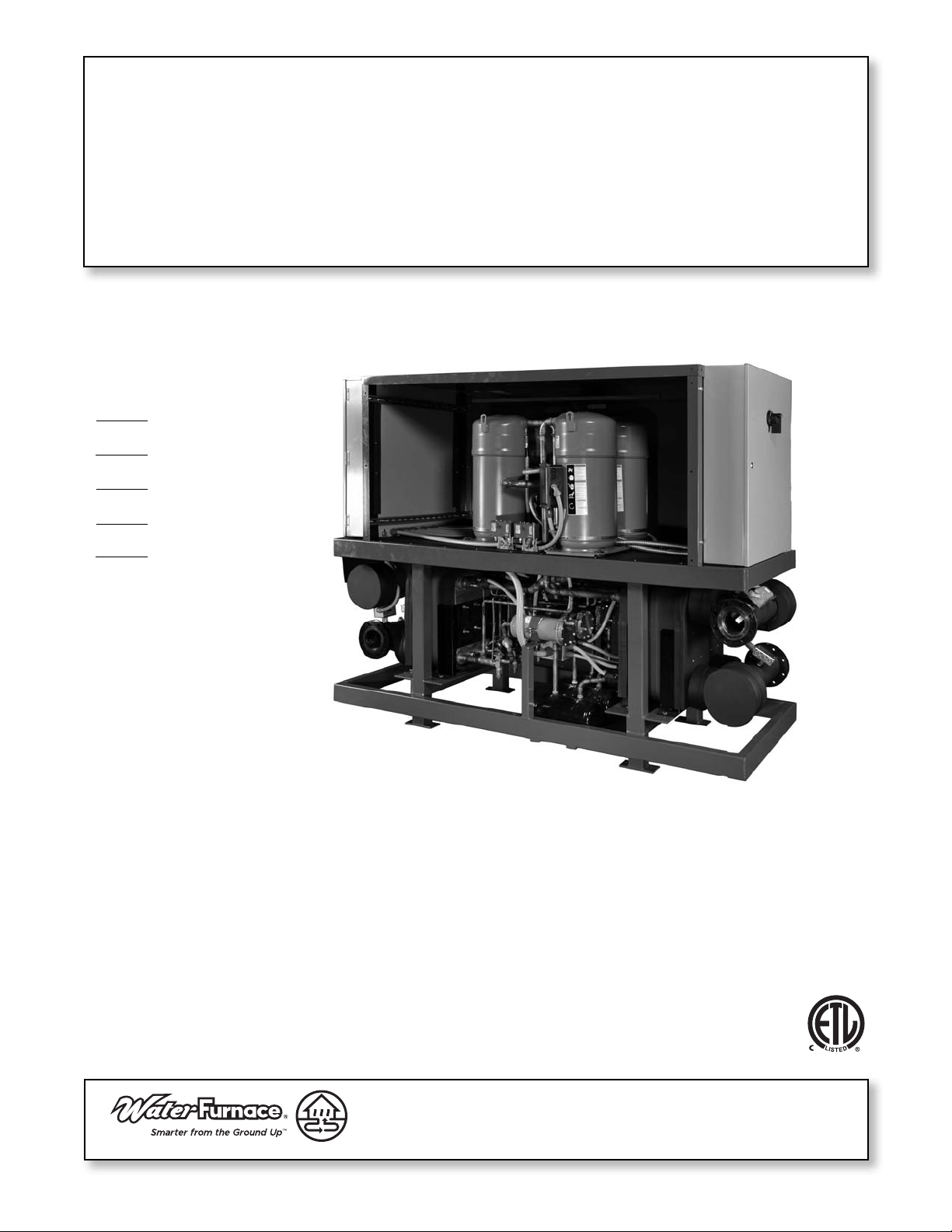
CLW Quad Series 60 to 140 Tons
Commercial Chiller - 60 Hz
Installation Information
Water Piping Connections
Electrical Data
Microprocessor Control
Startup Procedures
Preventive Maintenance
CLW Quad Series Chiller Installation Manual
IM1900WW 11/13
Page 2

Page 3

Table of Contents
Model Nomenclature . . . . . . . . . . . . . . . . . . . . . . . . . . . . . . . . . . . . . . . . . . . . . . . . . . . . . . . . . . . . . . 4
General Installation Information . . . . . . . . . . . . . . . . . . . . . . . . . . . . . . . . . . . . . . . . . . . . . . . . . . . . 5
CLW QUAD SERIES CHILLER INSTALLATION MANUAL
Physical Data
Field Connected Water Piping. . . . . . . . . . . . . . . . . . . . . . . . . . . . . . . . . . . . . . . . . . . . . . . . . . . . . . 7
Water Quality . . . . . . . . . . . . . . . . . . . . . . . . . . . . . . . . . . . . . . . . . . . . . . . . . . . . . . . . . . . . . . . . . . . . 8
System Cleaning and Flushing. . . . . . . . . . . . . . . . . . . . . . . . . . . . . . . . . . . . . . . . . . . . . . . . . . . . . . 9
Electrical Data . . . . . . . . . . . . . . . . . . . . . . . . . . . . . . . . . . . . . . . . . . . . . . . . . . . . . . . . . . . . . . . . . . . .11
Wiring Schematics . . . . . . . . . . . . . . . . . . . . . . . . . . . . . . . . . . . . . . . . . . . . . . . . . . . . . . . . . . . . .12-13
Field Wiring and Control Setup. . . . . . . . . . . . . . . . . . . . . . . . . . . . . . . . . . . . . . . . . . . . . . . . . . . . 14
Control Features. . . . . . . . . . . . . . . . . . . . . . . . . . . . . . . . . . . . . . . . . . . . . . . . . . . . . . . . . . . . . . .15-16
Sequence of Operation . . . . . . . . . . . . . . . . . . . . . . . . . . . . . . . . . . . . . . . . . . . . . . . . . . . . . . . . . . . 17
Reference Calculations . . . . . . . . . . . . . . . . . . . . . . . . . . . . . . . . . . . . . . . . . . . . . . . . . . . . . . . . . . . 18
Legend . . . . . . . . . . . . . . . . . . . . . . . . . . . . . . . . . . . . . . . . . . . . . . . . . . . . . . . . . . . . . . . . . . . . . . . . . 18
Unit Startup . . . . . . . . . . . . . . . . . . . . . . . . . . . . . . . . . . . . . . . . . . . . . . . . . . . . . . . . . . . . . . . . . . . . . 18
Pressure Drop . . . . . . . . . . . . . . . . . . . . . . . . . . . . . . . . . . . . . . . . . . . . . . . . . . . . . . . . . . . . . . . . . . . 19
Heat of Extraction/Rejection Data . . . . . . . . . . . . . . . . . . . . . . . . . . . . . . . . . . . . . . . . . . . . . . 20-21
. . . . . . . . . . . . . . . . . . . . . . . . . . . . . . . . . . . . . . . . . . . . . . . . . . . . . . . . . . . . . . . . . . . . . 6
Troubleshooting . . . . . . . . . . . . . . . . . . . . . . . . . . . . . . . . . . . . . . . . . . . . . . . . . . . . . . . . . . . . . . . . . 22
Heating and Cooling Cycle Analysis. . . . . . . . . . . . . . . . . . . . . . . . . . . . . . . . . . . . . . . . . . . . . . . .23
Startup and Troubleshooting Form. . . . . . . . . . . . . . . . . . . . . . . . . . . . . . . . . . . . . . . . . . . . . . . . .24
Preventive Maintenance . . . . . . . . . . . . . . . . . . . . . . . . . . . . . . . . . . . . . . . . . . . . . . . . . . . . . . . . . . 25
Service Parts List . . . . . . . . . . . . . . . . . . . . . . . . . . . . . . . . . . . . . . . . . . . . . . . . . . . . . . . . . . . . . . . .26
Revision Guide. . . . . . . . . . . . . . . . . . . . . . . . . . . . . . . . . . . . . . . . . . . . . . . . . . . . . . . . . . . . . . . . . . . 27
Page 4
CLW QUAD SERIES CHILLER INSTALLATION MANUAL
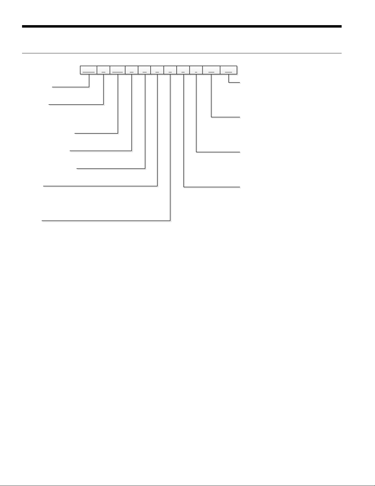
CLW
1-3 4 5-7 8 9 10
11 12 13
C 060 V Q 4 S S 1 1N
14-15SD15-16
Model Nomenclature
Model Type
CLW – Quad R-410A Series
Operation
C – Chiller
R – Heat Recovery
H – Heat Pump
Unit Capacity (Tons)
060, 080, 100, 120, 140
Compressor Series
V – Standard Series
Compressor Quantity
Q – Quad
Voltage
2 – 208-230/60/3
3 – 380/60/3
4 – 460/60/3
5 – 575/60/3
Chassis
S – Standard
Water
SD – Standard
NC – Non-Modular with Isolation Valves
NH – Non-Modular with Isolation Valves
and Head Pressure Control
Refrigeration
0N – EEV Optimized
1N – TEV
0H – EEV with Hot Gas Bypass
1H – TEV with Hot Gas Bypass
Electrical
0 – No Disconnect
1 – Non-Fused Disconnect
3 – Breaker
4 – Separate 120VAC Connection
Controls
S – Standard
N – No Local Interface
P – Primary
E – Enhanced Interface
W – Local Workstation Present
Rev.: 23 July 2013D
4
Page 5
General Installation Information
CLW QUAD SERIES CHILLER INSTALLATION MANUAL
Safety Considerations
Installing and servicing air conditioning and heating
equipment can be hazardous due to system pressure and
electrical components. Only trained and qualified service
personnel should install, repair or service heating and air
conditioning equipment. When working on heating and
air conditioning equipment, observe precautions in the
literature, tags and labels attached to the unit and other
safety precautions that may apply.
Follow all safety codes. Wear safety glasses and work
gloves. Use quenching cloth for brazing operations. Have
fire extinguisher available for all brazing operations.
NOTE: Before installing, check voltage of unit(s) to ensure
proper voltage.
WARNING: Before performing service or
maintenance operations on the system, turn off
main power switches to the unit. Electrical shock
could cause serious personal injury.
Application
Units are not intended for heating domestic (potable water)
by direct coupling. If used for this type of application, a
secondary heat exchanger must be used.
Moving and Storage
Move units in the normal “Up” orientation as indicated by
the labels on the unit packaging. When the equipment
is received, all items should be carefully checked against
the bill of lading to ensure that all crates and cartons
have been received in good condition. Examine units for
shipping damage, removing unit packaging if necessary
to properly inspect unit. Units in question should also
be internally inspected. If any damage is observed, the
carrier should make the proper notation on delivery receipt
acknowledging the damage. Units are to be stored in a
location that provides adequate protection from dirt, debris
and moisture.
WARNING: To avoid equipment damage, do not
leave the system filled in a building without heat
during cold weather, unless adequate freeze
protection levels of antifreeze are used. Heat
exchangers do not fully drain and will freeze
unless protected, causing permanent damage.
Unit Location
Provide sufficient room to make water and electrical
connections. If the unit is located in a confined space,
provisions must be made for unit servicing. Locate the
unit in an indoor area that allows easy removal of the
access panels and has enough space for service personnel
to perform maintenance or repair. These units are not
approved for outdoor installation and, therefore, must be
installed inside the structure being conditioned. Do not
locate units in areas subject to freezing conditions.
WARNING: Do not store or install units in
corrosive environments or in locations subject
to temperature or humidity extremes (e.g. attics,
garages, rooftops, etc.). Corrosive conditions and
high temperature or humidity can significantly
reduce performance, reliability, and service life.
WARNING: To avoid equipment damage and
possible voiding of warranty, be sure that
properly sized strainers are installed upstream
of both brazed plate heat exchangers to protect
them against particles in the fluid.
Unpacking the Unit
Remove the stretch warp and protective cardboard from
the unit. Where applicable, remove any additional crating or
bracketing and discard.
Units are setup to be side picked using a fork lift. Some
units include pick bars allowing for picking from the end
with required fork lengths. Note unit labels and markings
for safe picking points. Do not pick the unit up from points
not specified and keep the unit level during transport and
handling. Using improper equipment handling methods can
result in damage and/or void the warranty.
5
Page 6
CLW QUAD SERIES CHILLER INSTALLATION MANUAL
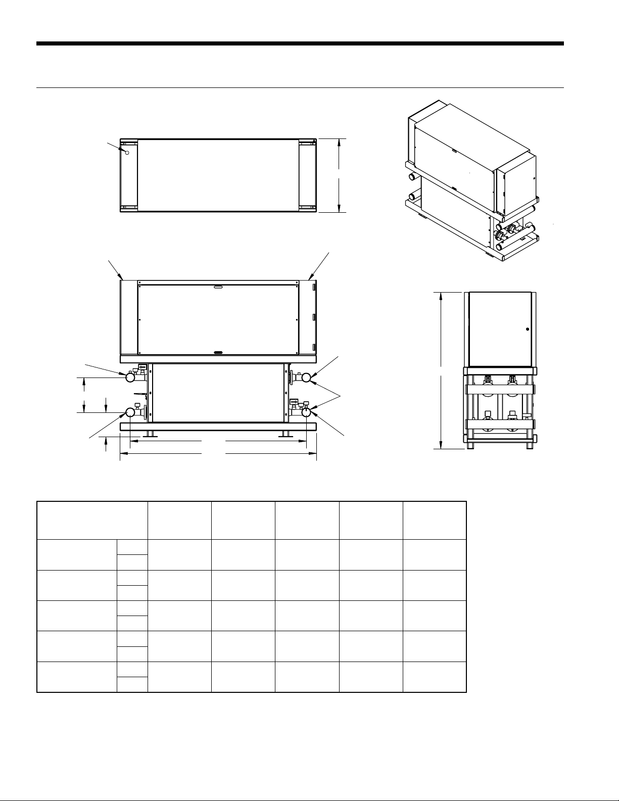
Physical Dimensions With Enclosure
Electrical
Connection
B
High Voltage
Elec Panel
CWR
(Inlet)
17.00
12.00
CWS
(Outlet)
Dimensional Data and Physical Data
A
Length
060
080
100
120
140
Model
in. 96 36 76 2976 22
cm. 243.8 91.4 193.0 1349.9 10.0
in. 96 36 76 3174 24
cm. 243.8 91.4 193.0 1439.7 10.9
in. 96 36 76 3352 24
cm. 243.8 91.4 193.0 1520.4 10.9
in. 100 36 76 3540 26
cm. 254.0 91.4 193.0 1605.7 11.8
in. 100 36 76 3642 28
cm. 254.0 91.4 193.0 1652.0 12.7
All dimensions in inches, [mm]
All water connections are 4 in. Victaulic
?
A
B
Width
C
Height
Low Voltage
Elec Panel
HWS
(Outlet)
4'' Victaulic
(standard)
HWR
(Inlet)
Weight
lbs [kg]
C
Charge
(per Circuit)
lbs [kg]
6
Page 7

Field Connected Water Piping
CLW QUAD SERIES CHILLER INSTALLATION MANUAL
General
System piping should be kept as simple as possible to
minimize the pressure drop, but hand valves should be field
installed to facilitate unit servicing. The piping installation
should provide service personnel with the ability to measure
and/or monitor water temperatures and pressures.
Source and load fluid connections are provided with 4-inch
[10.2cm] Victaulic grooved nipples. Each nipple will also
have a PT port installed for test and balance purposes.
It will be the installing contractor’s responsibility to
adequately support incoming piping to avoid damage to the
unit’s piping or heat exchangers. The water lines should be
routed so as not to interfere with access to the unit.
For any installation where the transmission of vibration
through the piping connections could cause unacceptable
noise levels in occupied spaces it is important to provide
adequate vibration damping. One method is to use the
optional Adapter Hose Kit (kit number TKC16S-4). This Kit
consists of four pieces of a braided stainless steel flexible
hose with a 4” Victaulic connection on one end and a 4”
MPT connection with pipe union on the other. Overall length
of each piece is 18”.
NOTE: Units are factory run-tested using propylene
glycol. Prior to connecting piping to unit, thoroughly flush
heat exchangers.
7
Page 8

CLW QUAD SERIES CHILLER INSTALLATION MANUAL
Field Connected Water Piping cont.
Before final connection to the unit, the supply and return
hose kits must be connected to each other, bypassing
the unit, and the system flushed to remove dirt, piping
chips and other foreign material. Normally, a combination
balancing and close-off (ball) valve is installed at the return,
and a rated gate or ball valve is installed at the supply. The
return valve can be adjusted to obtain the proper water
flow. The valves allow the unit to be removed for servicing.
The proper water flow must be delivered to each unit
whenever the unit heats or cools. The proper flow rate
cannot be accurately set without measuring the water
pressure drop through the refrigerant-to-water heat
exchanger. A 3 GPM flow rate per ton [0.054 LPS per kW]
of cooling capacity (2.25 GPM per ton [0.0404 LPS per
kW] minimum) is required.
NOTE: The placement and connection of the water
circulating pump(s) must be taken into consideration prior
to designing the final water piping systems.
Closed Loop Tower/Boiler Systems
The water loop is usually maintained between 60°F [15.5°C]
and 90°F [32.2°C] for proper heating and cooling operation.
This is accomplished with a cooling tower and a boiler.
Earth Coupled Systems
All supply and return water piping should be insulated to
prevent excess condensation from forming on the water
lines. Ensure pumping system is capable of providing
adequate flow rate at the system pressure drop, 3.0 GPM
per ton [0.054 LPS per kW] (source side) is recommended.
Antifreeze in the loop is strongly recommended.
To reject excess heat from the condenser water loop, the
use of a closed-circuit evaporative cooler or an open type
cooling tower with a secondary heat exchanger between
the tower and the condenser water loop is recommended.
If an open type cooling tower is used without a secondary
heat exchanger, continuous chemical treatment and filtering
of the water must be performed to ensure the water is free
from damaging materials.
CAUTION: Water piping exposed to outside
temperature may be subject to freezing.
Open Loop Well Water Systems
Installation of an open loop system is not recommended
without using a secondary heat exchanger unless water
quality guidelines are met.
8
Page 9
Water Quality
CLW QUAD SERIES CHILLER INSTALLATION MANUAL
General
Commercial chiller systems may be successfully applied in a
wide range of commercial and industrial applications. It is the
responsibility of the system designer and installing contractor
to ensure that acceptable water quality is present and that all
applicable codes have been met in these installations.
Water Treatment
Do not use untreated or improperly treated water. Equipment
damage may occur. The use of improperly treated or
untreated water in this equipment may result in scaling,
erosion, corrosion, algae or slime. The services of a qualified
water treatment specialist should be engaged to determine
what treatment, if any, is required. The product warranty
specifically excludes liability for corrosion, erosion or
deterioration of equipment.
The heat exchangers in the units are 316 stainless steel plates
with copper brazing. The water piping in the heat exchanger
is steel. There may be other materials in the building’s piping
system that the designer may need to take into consideration
when deciding the parameters of the water quality.
If an antifreeze or water treatment solution is to be used, the
designer should confirm it does not have a detrimental effect
on the materials in the system.
Contaminated Water
In applications where the water quality cannot be held to
prescribed limits, the use of a secondary or intermediate heat
exchanger is recommended to separate the unit from the
contaminated water.
The following table outlines the water quality guidelines
for unit heat exchangers. If these conditions are exceeded,
a secondary heat exchanger is required. Failure to supply
a secondary heat exchanger where needed will result in a
warranty exclusion for primary heat exchanger corrosion or
failure.
Strainers
These units must have properly sized strainers upstream of
both brazed plate heat exchangers to protect them against
particles in the fluid. Failure to install proper stainers and
perform regular service can result in serious damage to the
unit, and cause degraded performance, reduced operating
life and failed compressors. Improper installation of the unit
(which includes not having proper strainers to protect the
heat exchangers) can also result in voiding the warranty.
Field supplied strainers with 20-40 mesh (530-1060 microns)
are recommended, with 30 mesh (800 microns) being the
optimum choice. The strainers selected should have a mesh
open area of at least 6 square inches (39 square centimeters)
for each unit being serviced by the strainer. Using strainers
with a smaller amount of open area will result in the need for
more frequent cleaning.
Strainers should be selected on the basis of acceptable
pressure drop, and not on pipe diameter. The strainers
selected should have a pressure drop at the nominal flow rate
of the units; low enough to be within the pumping capacity of
the pump being used.
WARNING: Must have intermediate heat
exchanger when used in pool applications.
Water Quality Guidelines
Material Copper 90/10 Cupronickel 316 Stainless Steel
pH Acidity/Alkalinity
Scaling
Corrosion
Iron Fouling
(Biological Growth)
Erosion
NOTES: Grains = ppm divided by 17
mg/L is equivalent to ppm
Calcium and
Magnesium Carbonate
Hydrogen Sulfide
Chlorine Less than 0.5 ppm Less than 0.5 ppm Less than 0.5 ppm
Chlorides Less than 20 ppm Less than 125 ppm Less than 300 ppm
Carbon Dioxide Less than 50 ppm 10 - 50 ppm 10 - 50 ppm
Ammonia Less than 2 ppm Less than 2 ppm Less than 20 ppm
Ammonia Chloride Less than 0.5 ppm Less than 0.5 ppm Less than 0.5 ppm
Ammonia Nitrate Less than 0.5 ppm Less than 0.5 ppm Less than 0.5 ppm
Ammonia Hydroxide Less than 0.5 ppm Less than 0.5 ppm Less than 0.5 ppm
Ammonia Sulfate Less than 0.5 ppm Less than 0.5 ppm Less than 0.5 ppm
Total Dissolved Solids (TDS) Less than 1000 ppm 1000 - 1500 ppm 1000 - 1500 ppm
LSI Index +0.5 to -0.5 +0.5 to -0.5 +0.5 to -0.5
Iron, FE
Bacterial Iron Potential
Iron Oxide
Suspended Solids
Threshold Velocity
(Fresh Water)
Less than 0.5 ppm (rotten egg
Sulfates Less than 125 ppm Less than 125 ppm Less than 200 ppm
2
+ (Ferrous)
smell appears at 0.5 ppm)
Less than 1 ppm, above this
level deposition will occur
Less than 10 ppm and filtered
for max. of 600 micron size
7 - 9 7 - 9 7 - 9
(Total Hardness)
less than 350 ppm
< 0.2 ppm < 0.2 ppm < 0.2 ppm
< 6 ft/sec < 6 ft/sec < 6 ft/sec
(Total Hardness)
less than 350 ppm
10 - 50 ppm Less than 1 ppm
Less than 1 ppm, above this
level deposition will occur
Less than 10 ppm and filtered
for max. of 600 micron size
(Total Hardness)
less than 350 ppm
Less than 1 ppm, above this
level deposition will occur
Less than 10 ppm and filtered
for max. of 600 micron size
9
2/22/12
Page 10

CLW QUAD SERIES CHILLER INSTALLATION MANUAL
System Cleaning and Flushing
Cleaning and Flushing
Prior to start up of any heat pump, the water circulating
system must be cleaned and flushed of all dirt and debris.
If the system is equipped with water shutoff valves, the
supply and return runouts must be connected together
at each unit location (This will prevent the introduction of
dirt into the unit, see Flushing with Water Shutoff Valve
Equipped Systems illustration). The system should be filled
at the water make-up connection with all air vents open.
After filling, vents should be closed.
Flushing with Water Shutoff Valve Equipped Systems
Return Runout
Supply Runout
Mains
Rubber Hose
Runouts Initially
Connected Together
The contractor should start the main circulator with the
pressure reducing valve makeup open. Vents should be
checked in sequence to bleed off any trapped air and to
verify circulation through all components of the system.
As water circulates through the system, the contractor
should check and repair any leaks found in the piping
system. Drain(s) at the lowest point(s) in the system should
be opened for initial flush and blowdown, making sure
water fill valves are set at the same rate. Check the pressure
gauge at the pump suction and manually adjust the makeup water valve to hold the same positive pressure both
before and after opening the drain valves. Flushing should
continue for at least two hours, or longer if required, until
drain water is clean and clear.
The supplemental heater and/or circulator pump, if used,
should be shut off. All drains and vents should be opened
to completely drain the system. Short-circuited supply and
return runouts should now be connected to the unit supply
and return connections.
Refill the system with clean water. Test the system water
for acidity and treat as required to leave the water slightly
alkaline (pH 7.5 to 8.5). The specified percentage of
antifreeze may also be added at this time. Use commercial
grade antifreeze designed for HVAC systems only.
Environol™ brand antifreeze is recommended.
Once the system has been filled with clean water and
antifreeze (if used), precautions should be taken to protect
the system from dirty water conditions. Dirty water will
result in system-wide degradation of performance, and
solids may clog valves, strainers, flow regulators, etc.
Additionally, the heat exchanger may become clogged
which reduces compressor service life and can cause
premature unit failure.
In boiler/tower application, set the loop control panel
set points to desired temperatures. Supply power to all
motors and start the circulating pumps. After full flow has
been established through all components including the
heat rejector (regardless of season), air vented and loop
temperatures stabilized, each of the units will be ready for
check, test and start up and for air and water balancing.
Ground Source Loop System Checkout
Once piping is completed between the unit pumping
system and ground loop, final purging and charging of
the loop is needed. A high pressure pump is needed to
achieve adequate flow velocity in the loop to purge air
and dirt particles from the loop itself. Antifreeze solution
is used in most areas to prevent freezing. Flush the
system adequately to remove as much air as possible;
then pressurize the loop to a static pressure of 40-50
PSI (summer) or 50-75 PSI (winter). This is normally
adequate for good system operation. Loop static pressure
may decrease soon after initial installation, due to pipe
expansion and loop temperature change. Running the
unit for at least 30 minutes after the system has been
completely purged of air will allow for the “break-in”
period. It may be necessary to adjust static loop pressure
(by adding water) after the unit has run for the first time.
Loop static pressure will also fluctuate with the seasons.
Pressures will be higher in the winter months than during
the cooling season. This fluctuation is normal and should be
considered when charging the system initially.
Ensure the pump provides adequate flow through the unit
by checking pressure drop across the heat exchanger.
Usually 2.25-3.0 GPM of flow per ton of cooling capacity is
recommended in earth loop applications.
10
Page 11

Electrical Data
CLW QUAD SERIES CHILLER INSTALLATION MANUAL
Model
060
080
100
120
140
Notes:
1. Where RLA1 is equal to the largest compressor in the system and the others RLA's are all subsequent
motors present in the system.
2. Total unit MCA shall not exceed 500A or a second connection will be required.
Rated
Voltage
208-230/60/3 187/253
460/60/3 414/506 43.0 27.6 35.0 117.3 144.9
575/60/3 517/633 34.4 22.0 28.0 93.5 115.5
208-230/60/3 187/253
460/60/3 414/506 54.1 34.7 48.8 147.5 182.2
575/60/3 517/633 43.3 27.8 39.1 118.2 146.0
208-230/60/3 187/253
460/60/3 414/506 63.5 40.7 53.2 173.0 213.7
575/60/3 517/633 50.8 32.6 42.6 138.6 171.2
208-230/60/3 187/253
460/60/3 414/506 82.8 53.1 65.6 225.7 278.8
575/60/3 517/633 66.3 42.5 52.5 180.6 223.1
208-230/60/3 187/253
460/60/3 414/506 80.2 51.4 75.0 218.5 269.9
575/60/3 517/633 64.2 41.1 60.0 174.7 215.8
Voltage
Min/Max
HP
15
20
25
30
35
MCC RLA1 MOA MCA HP MOCP
89.9 57.6 77.3 244.8
110.7 70.9 108.0 301.3
132.8 85.1 117.7 361.7
165.6 106.2 145.1 451.4
160.4 102.8 165.8 436.9
Compressor Unit
302.4
60
372.2
80
446.8
100
557.6
120
539.7
140
11/05/13
MCA (Maximum Current Rating) is a calculation based off the RLA of the compressor on the electrical connection
and is used to properly size the wire. Please refer to NEC for additional information.
MOCP (Maximum Over Current Protection) is a calculation based off the RLA of the compressor on the electrical
connection and is used to fuses and breakers. Please refer to NEC for additional information.
11
Page 12

CLW QUAD SERIES CHILLER INSTALLATION MANUAL
WIRE LEGEND
(TB-P7): 120VAC Power (Comp 3&4)
(TB-P12): 24 VAC Power (Circuit 1 & 2)
(TB-P5): 120 VAC switch power
(TB-P11): 24 VAC switch power
(TB-P16):24VDC switch power
(TB-P13): 24 VAC Power (Circuit 3 & 4)
(TB-P8): 120 VAC Neutral (Comp 1&2)
(TB-P9): 120VAC Neutral (Comp 3&4)
(TB-P14): 24 VAC Neutral (Circuit 1 & 2)
(TB-P15): 24 VAC Neutral (Circuit 3 & 4)
(TB-P17): 24 VDC Power (Circuit 1 & 2)
(TB-P20): 24 VDC Neutral (Circuit 3 & 4)
(TB-P10): 120VAC Ground
(TB-P2): 120 VAC Power (Outlets & Heaters)
(TB-P1): 120 VAC switch power
(TB-P3): 120 VAC Neutral (Outlets & Heaters)
(TB-P4): 120 VAC Ground
(Outlets)
(
TB
-
P
6
)
(TB-P6): 120 VAC Power (Comp 1&2)
(TB-P19): 24 VDC Neutral (Circuit 1 & 2)
(Outlets)
(TB-P2)
(RIB-2.1 & Outlets)
(
R
-
3
.
13
,
TB-
B
22
)
(
RIB-
7
.1
)
(
RIB
-
1
.
1
)
INPUT/OUTPUT SIGNAL
INPUT/OUTPUT COMMON
120VAC, 24VAC
120VAC (+)/ 24VDC (-)
GROUND
24VAC &24VDC (+)
BLACK
WHITE
GREEN
RED
BLUE
GRAY
(
R
-
9
.
13
,
TB
-
Y
22
)
(
KMC
-
U
1
,
2
,
3
)
(
K
MC
-
U
4
,
5
,
6
&
TB-
O
1
9
)
(
KMC
-
U
1
,
2
,3
)
(KMC
-
U
4
,
5,
6
& TB
-
B
20
)
(
U2
-
C
-
5
,
U
3
-
C
-
5
)
(U5
-C
-
5,
U6-
C
-5
)
(
TB
-
O
4
)
ETHERNET WIRE
(TB-P18): 24 VDC Power (Circuit 3 & 4)
10A
10A
5A
1A
120 VAC POWER 24 VAC POWER 24 VDC POWER COMPRESSOR 2 SENSORSWATER TEMP SENSORS & CONTROL VALVES
(
120
VAC
Transformer
)
(24 VACTransformer)
(24 VDCTransformer)
(120 VAC
Transformer)
120VAC 15A Duplex
Receptacle
(
T
B
-
G
4
)
COMPRESSOR 1 SENSORS
(
TB
-
P12
)
(
TB
-
P
1
7
)
LOW VOLTAGE PANEL LAYOUT
UNIT TYPE:
UNIT MODEL:
SERIAL NUMBER:
Touch Screen IP: ________________________ (Assigned)
Master Controller IP: _____________________ (Assigned)
Chipkin Field Server IP:___________________ (Assigned)
START-UP DATE:
START-UP TECHNICIAN:
CHILLIT CHILLERS LLC PH: (574) 970-3035
Rev: E 08/01/13 CPM
© CHILLIT CHILLERS 2013
(TB-B19):Isolation Valves (24VAC)
(TB-B20):Isolation Valve (common)
(TB-B10) +24 VAC
(
T
B
-
B11
, U
1
-
G
-
16
)
(TB-B1): Evaporator Inlet C1&C2
(TB-B2): Common TBG1 & 3
(TB-B3): Evaporator Outlet Temp C1&C2
(U1-IN1-1)
(U1-C-2)
(U1-IN2-3)
(TB-B9): Evaporator Outlet Temp C3&C4
(TB-B8): Common TBG8&10
(TB-B21):C1&2 Isolation Valves Signal
(TB-B22): C3&4 Isolation Valve Signal
(TB-B18): Condenser Header Outlet Temp
(TB-B17): Common TBG20
(TB-O1): C1-Condenser Liquid Temp
(TB-O2): Common TBG1 & 3
(TB-O3): C1-Evaporator Gas Temp
(TB-O4): C1-Discharge Pressure
(TB-O5): C1-Discharge Pressure
(TB-O10): C1- Motor Protect Alarm
(TB-O12): C1-High Pressure Alarm
(TB-O13): C1-Low Pressure ALarm
(TB-O6): C1-Suction Pressure
(TB-O8): C1-Current Transducer
(TB-O9): C1-Current Transducer
(TB-O7): C1-Suction Pressure
(R-1.14)
(R-3.14)
(R-4.14)
(U2-IN1-1)
(U2-IN2-3)
(U1-IN3-4)
(U2-IN4-6)
(TB-P17) +24vDc
(TB-O4) +24vDc
(TB-Y1): C2-Condenser Liquid Temp
(TB-Y2): Common TBG1 & 3
(TB-Y3): C2-Evaporator Gas Temp
(TB-Y4): C2-Discharge Pressure
(TB-Y5): C2-Discharge Pressure
(TB-Y10): C2-Motor Protect
(TB-Y12): C2-High Pressure Alarm
(TB-Y13): C2-Low Pressure Alarm
(TB-Y6): C2-Suction Pressure
(TB-Y8): C2-Current Transducer
(TB-Y9): C2-Current Transducer
(TB-Y7): C2-Suction Pressure
(R-5.14)
(R-7.14)
(R-8.14)
(U3-IN1-1)
(U3-C-2)
(U3-IN2-3)
(U3-IN3-4)
(U3-IN4-6)
(TB-O8) +24vDc
(TB-Y4) +24vDc
(U2-IN5-7)
(
TB
-
O
6
) +
24
v
Dc
(U3-IN5-7)
(TB-Y6) +24vDc
(TB-Y11): C2-Thermal Overload Alarm
(TB-O11): C1- Thermal Overload Alarm
(R-2.14)
(R-6.14)
COMPRESSOR 4 SENSORSCOMPRESSOR 3 SENSORS
(TB-G1): C3-Condenser Liquid Temp
(TB-G2): Common TBG1 & 3
(TB-G3): C3-Evaporator Gas Temp
(TB-G4): C3-Discharge Pressure
(TB-G3): C3-Discharge Pressure
(TB-G10): C3- Motor Protect Alarm
(TB-G12): C3-High Pressure Alarm
(TB-G13): C3-Low Pressure ALarm
(TB-G6): C3-Suction Pressure
(TB-G8): C3-Current Transducer
(TB-G9): C3-Current Transducer
(TB-G7): C3-Suction Pressure
(R-9.14)
(R-11.14)
(R-12.14)
(U5-IN1-1)
(U5-C-2)
(U5-IN2-3)
(U5-IN3-4)
(U5-IN4-6)
(TB-P18) +24vDc
(TB-G4) +24vDc
(TB-N1): C4-Condenser Liquid Temp
(TB-N2): Common TBG1 & 3
(TB-N3): C4-Evaporator Gas Temp
(TB-N4): C4-Discharge Pressure
(TB-N5): C4-Discharge Pressure
(TB-N10): C4-Motor Protect
(TB-N12): C4-High Pressure Alarm
(TB-N13): C4-Low Pressure Alarm
(TB-N6): C4-Suction Pressure
(TB-N8): C4-Current Transducer
(TB-N9): C4-Current Transducer
(TB-N7): C4-Suction Pressure
(R-13.14)
(R-15.14)
(R-16.14)
(U6-IN1-1)
(U6-C-2)
(U6-IN2-3)
(U6-IN3-4)
(U6-IN4-6)
(TB-G8) +24vDc
(TB-N4) +24vDc
(U5-IN5-7)
(
TB
-
G6
)
+24
v
Dc
(U6-IN5-7)
(TB-N6) +24vDc
(TB-N11): C4-Thermal Overload Alarm
(TB-G11): C3- Thermal Overload Alarm
(R-10.14)
(R-14.14)
(TB-Z1): Enable Compressor 1
(TB-Z3): 120 VAC Neutral
(TB-Z5): Enable Compressor 2
(RIB-1.2)
(RIB-2.2)
(TB-Z2): Enable Heat Comp1
(TB-Z6): 120 VAC Neutral
(TB-Z7): Enable Heat Comp2
(RIB-3.2)
(RIB-4.2)
(TB-Z4): Reset Compressor 1
(TB-Z9): 120 VAC Neutral
(TB-Z8): Reset Compressor 2
(RIB-5.2)
(RIB-6.2)
(TB-P9)
(TB-Z3)
(TB-Z6)
(TB-Z19): Ground
(TB-Z10): Enable Compressor 3
(TB-Z12): 120 VAC Neutral
(TB-Z14): Enable Compressor 4
(TB-Z11): Enable Heat Comp3
(TB-Z15): 120 VAC Neutral
(TB-Z16): Enable Heat Comp4
(TB-Z13): Reset Compressor 3
(TB-Z18): 120 VAC Neutral
(TB-Z17): Reset Compressor 4
ENABLE COMPRESSORS & RESET
RIB-2
Heater C1
RIB-5
Heater C2
RIB-3
Reset C1
RIB-6
Reset C2
(TB-P2_120V+)
(RIB-2.1_120V+)
(TB-Z8)
(TB-Z4)
(TB-Z7)
(TB-Z2)
RIB-1
Enable C1
RIB-4
Enable C2
(
TB
-
P
6
)
(TB-Z5)
(TB-Z1)
(RIB-4.1_120V+)
(RIB-1.1_120V+)
(RIB-3.1_120V+)
(U2-G-4 & RIB-2.5)
(U2-OUT1-1)
(U3-G-4)
(U3-OUT1-1)
(RIB-1.5)
(U2-OUT2-3)
(U3-G-4)
(
U
3
-
OUT
2
-
3
)
(
U
2
-
G
-
8
)
(
U
2-
O
U
T
4-
7
)
(U3-G-8)
(U3-OUT4-7)
RIB-8
Heater C3
RIB-11
Heater C4
RIB-9
Reset C3
RIB-12
Reset C4
(R
I
B-5
.
1
_
1
2
0
V
+)
(RIB-8.1_120V+)
(TB-Z8)
(TB-Z4)
(TB-Z7)
(TB-Z2)
RIB-7
Enable C3
RIB-10
Enable C4
(TB-P7)
(TB-Z5)
(TB-Z1)
(RIB-10.1_120V+)
(RIB-7.1_120V+)
(
R
I
B
-
9
.
1_
120
V
+
)
(U5-G-4)
(U5-OUT1-1)
(U6-G-4)
(U6-OUT1-1)
(U5-G-4)
(U5-OUT2-3)
(U6-G-4)
(U6-OUT2-3)
(U5-G-8)
(U5-OUT4-7)
(U6-G-8)
(U6-OUT4-7)
1
(TB-Y10)
(R-4.13)
(TB-Y12)
(R-6.13)
(TB-Y13)
(R-7.13)
R-5
[120VAC]
Comp-2
MotorProtect
Alarm
R-7
[120VAC]
Comp-2
HighPressure
Alarm
R-8
[120VAC]
Comp-2
LowPressure
Alarm
(TB-O10)
(TB-P11)
(TB-O12)
(R-2.13)
(U2-IN6-9)
(U2-IN7-10)
(TB-O13)
(R-3.13)
(U2-IN8-12)
5(NO)
13(-)
9
1(NC)
14(+)
R-1
[120VAC]
Comp-1
MotorProtect
Alarm
R-3
[120VAC]
Comp-1
HighPressure
Alarm
R-4
[120VAC]
Comp-1
LowPressure
Alarm
(U2-C-11)
(R-2.5)
(R-3.5)
(U3-IN6-9)
(U3-IN7-10)
(U3-IN8-12)
(U3-C-11)
(R-6.5)
(R-7.5)
R-6
[120VAC]
Comp-2
Thermal
Overload
Alarm
(TB-O11)
(R-1.13)
(U2-IN6-9)
R-2
[120VAC]
Comp-1
Thermal
Overload
Alarm
(R-1.5)
(TB-Y11)
(R-5.13)
(U3-IN6-9)
(TB-B1)
(TB-B2)
(eSC-1)
(eSC-3)
(eSC-2)
(TB-B3)
(TB-B4)
(TB-B5)
(TB-B6)
(TB-B13)
(TB-B14)
NOTE: Pressuresensors &CT’s require resistors and DIP switches
(TB-P14)
(TB-P12)
(TB-P19)
(U1-IN1-1)
(U1-C-2)
(U1-IN2-3)
(U1-IN3-4)
(U1-C-5)
(U1-IN4-6)
(U1-IN5-7)
(U1-C-8)
(U1-IN6-9)
(U1-IN7-10)
(U1-C-11)
(U1-IN8-12)
Evap Inlet (Return) Temp C1 C2
Common IN1 & IN2
Evap Outlet (Supply) Temp C1 C2
Cond Inlet (Return) Temp C1 C2
Common IN3 & IN4
Cond Outlet (Supply) Temp C1 C2
Evap/Cond Flow Switch C1 C2
Common IN5 & IN6
[A]
[A]
Common IN7 & IN8
[A]
Input ID
U1 -A
U1 +B
U1 ϛ
U1 24Vac c
U1 24Vac U1 24Vac +
[A]
[A]
Common Out1 & Out2
[A]
[A]
Common Out3 & Out4
Output ID
[A]
Evap/Cond Iso 2-Way C1 C2
Common Out5 & Out6
[A]
[A]
U1-OUT1-1
U1-OUT2-3
U1-G-4
U1-OUT3-5
U1-OUT4-7
U1-G-8
U1-OUT5-9
U1-OUT6-11
U1-G-12
U1-OUT7-13
U1-OUT8-15
Common Out5 & Out6
U1-G-16
U1 – MASTER TEMPS C1 & C2
(U2-IN1-1)
(U2-C-2)
(U2-IN2-3)
(U2-IN3-4)
(U2-C-5)
(U2-IN4-6)
C1-Condenser Liquid Temp
Common IN1 & IN2
C1-Evaporator Gas Temp
C1- Discharge Pressure
Common IN3 & IN4
Input ID
C1-Suction Pressure
(U2-IN5-7)
(U2-C-8)
(U2-IN6-9)
(U2-IN7-10)
(U2-C-11)
(U2-IN8-12)
C1-Current Transducer (CT)
Common IN5 & IN6
C1-Motor+ Thermal Alarm
C1-High Pressure Alarm
Common IN7 & IN8
C1- Low Pressure Alarm
C1 – Enable Compressor
C1 – Crank Heater
Common Out1 & Out2
Not Used
C1 – Momentary Reset
Common Out3 & Out4
Output ID
Not Used
Not Used
Common Out5 & Out6
Not Used
Not Used
U2-OUT1-1
U2-OUT2-3
U2-G-4
U2-OUT3-5
U2-OUT4-7
U2-G-8
U2-OUT5-9
U2-OUT6-11
U2-G-12
U2-OUT7-13
U2-OUT8-15
Common Out5 & Out6
U2-G-16
U2 - COMPRESSOR 1
(
T
B
-
P
14
)
(
T
B
-
P1
2
)
(TB-Z19)
U2 24Vac c
U2 24Vac U2 24Vac +
(
U1
+
B
)
(
U
1
ϛ
)
(
U
1
-
A
)
U2 -A
U2 +B
U2 ϛ
(U3-IN1-1)
(U3-C-2)
(U3-IN2-3)
(U3-IN3-4)
(U3-C-5)
(U3-IN4-6)
C2-Condenser Liquid Temp
Common IN1 & IN2
C2-Evaporator Gas Temp
C2-Discharge Pressure
Common IN3 & IN4
Input ID
C2-Suction Pressure
(U3-IN5-7)
(U3-C-8)
(U3-IN6-9)
(U3-IN7-10)
(U3-C-11)
(U3-IN8-12)
C2-Current Transducer (CT)
Common IN5 & IN6
C2- Motor + Thermal Alarm
C2-High Pressure Alarm
Common IN7 & IN8
C2-Low Pressure Alarm
C2 – Enable Compressor
C2- Crank Heater
Common Out1 & Out2
Not Used
C2 – Momentary Reset
Common Out3 & Out4
Output ID
Not Used
Not Used
Common Out5 & Out6
Not Used
Not Used
U3-OUT1-1
U3-OUT2-3
U3-G-4
U3-OUT3-5
U3-OUT4-7
U3-G-8
U3-OUT5-9
U3-OUT6-11
U3-G-12
U3-OUT7-13
U3-OUT8-15
Common Out5 & Out6
U3-G-16
U3 - COMPRESSOR 2
(
T
B
-
P
1
4
)
(
T
B
-
P
1
2
)
(
T
B
-
Z
1
9
)
U3 24Vac c
U3 24Vac U3 24Vac +
U3 -A
U3 +B
U3 ϛ
250Ω
250Ω
250Ω
250Ω
250Ω
250Ω
(
U
2
+
B
)
(
U
2
ϛ
)
(
U
2
-
A
)
NOTE: Pressuresensors &CT’s require resistors and DIP switches
(U4-IN1-1)
(U4-C-2)
(U4-IN2-3)
(U4-IN3-4)
(U4-C-5)
(U4-IN4-6)
(U4-IN5-7)
(U4-C-8)
(U4-IN6-9)
(U4-IN7-10)
(U4-C-11)
(U4-IN8-12)
Evap Inlet (Return) Temp C3 C4
Common IN1 & IN2
EvapOutlet (Supply)TempC3 C4
CondInlet (Return)Temp C3C4
Common IN3 & IN4
CondOutlet (Supply)Temp C3C4
Evap/Cond Flow Switch C3 C4
Common IN5 & IN6
[A]
Evap Header Outlet Temp
Common IN7 & IN8
Cond Header Outlet Temp
Input ID
U4 -A
U4 +B
U4 ϛ
U4 24Vac c
U4 24Vac U4 24Vac +
[A]
[A]
Common Out1 & Out2
[A]
[A]
Common Out3 & Out4
Output ID
[A]
Evaporator Iso 2-Way C3 C4
Common Out5 & Out6
Condenser Iso 2-way C3 C4
[A]
U4-OUT1-1
U4-OUT2-3
U4-G-4
U1-2-OUT3-5
U4-OUT4-7
U4-G-8
U4-OUT5-9
U4-OUT6-11
U4-G-12
U4-OUT7-13
U4-OUT8-15
Common Out5 & Out6
U4-G-16
U4 – MASTER TEMPS C3 & C4
(U5-IN1-1)
(U5-C-2)
(U5-IN2-3)
(U5-IN3-4)
(U5-C-5)
(U5-IN4-6)
C3-Condenser Liquid Temp
Common IN1 & IN2
C3-Evaporator Gas Temp
C3- Discharge Pressure
Common IN3 & IN4
Input ID
C3-Suction Pressure
(U5-IN5-7)
(U5-C-8)
(U5-IN6-9)
(U5-IN7-10)
(U5-C-11)
(U5-IN8-12)
C3-Current Transducer (CT)
Common IN5 & IN6
C3-Motor+ Thermal Alarm
C3-High Pressure Alarm
Common IN7 & IN8
C3- Low Pressure Alarm
C3 – Enable Compressor
C3 – Crank Heater
Common Out1 & Out2
Not Used
C3 – Momentary Reset
Common Out3 & Out4
Output ID
Not Used
Not Used
Common Out5 & Out6
Not Used
Not Used
U5-OUT1-1
U5-OUT2-3
U5-G-4
U5-OUT3-5
U5-OUT4-7
U5-G-8
U5-OUT5-9
U5-OUT6-11
U5-G-12
U5-OUT7-13
U5-OUT8-15
Common Out5 & Out6
U5-G-16
U5 - COMPRESSOR 3
U5 24Vac c
U5 24Vac U5 24Vac +
U5 -A
U5 +B
U5 ϛ
(U6-IN1-1)
(U6-C-2)
(U6-IN2-3)
(U6-IN3-4)
(U6-C-5)
(U6-IN4-6)
C4-Condenser Liquid Temp
Common IN1 & IN2
C4-Evaporator Gas Temp
C4-Discharge Pressure
Common IN3 & IN4
Input ID
C4-Suction Pressure
(U6-IN5-7)
(U6-C-8)
(U6-IN6-9)
(U6-IN7-10)
(U6-C-11)
(U6-IN8-12)
C4-Current Transducer (CT)
Common IN5 & IN6
C4- Motor + Thermal Alarm
C4-High Pressure Alarm
Common IN7 & IN8
C4-Low Pressure Alarm
C4 – Enable Compressor
C4- Crank Heater
Common Out1 & Out2
Not Used
C4 – Momentary Reset
Common Out3 & Out4
Output ID
Not Used
Not Used
Common Out5 & Out6
Not Used
Not Used
U6-OUT1-1
U6-OUT2-3
U6-G-4
U6-OUT3-5
U6-OUT4-7
U6-G-8
U6-OUT5-9
U6-OUT6-11
U6-G-12
U6-OUT7-13
U6-OUT8-15
Common Out5 & Out6
U6-G-16
U6 - COMPRESSOR 4
U6 24Vac c
U6 24Vac U6 24Vac +
U6 -A
U6 +B
U6 ϛ
250Ω
250Ω
250Ω
250Ω
250Ω
250Ω
(TB-N10)
(R-12.13)
(TB-N12)
(R-14.13)
(TB-N13)
(R-15.13)
R-13
[120VAC]
Comp-4
MotorProtect
Alarm
R-15
[120VAC]
Comp-4
HighPressure
Alarm
R-16
[120VAC]
Comp-4
LowPressure
Alarm
(TB-G10)
(R-8.13)
(TB-G12)
(R-10
.
13
)
(U5-IN6-9)
(U5-IN7-10)
(TB-G13)
(R-11.13)
(U5-IN8-12)
R-9
[120VAC]
Comp-3
MotorProtect
Alarm
R-11
[120VAC]
Comp-3
HighPressure
Alarm
R-12
[120VAC]
Comp-3
LowPressure
Alarm
(U
5
-C-11)
(R-10.5)
(R-11.5)
(U6-IN6-9)
(U6-IN7-10)
(U6-IN8-12)
(U6-C-11)
(R-14.5)
(R-15.5)
R-14
[120VAC]
Comp-4
Thermal
Overload
Alarm
(TB-G11)
(R-9.13)
(U5-IN6-9)
R-10
[120VAC]
Comp-3
Thermal
Overload
Alarm
(R-9.5)
(TB-N11)
(R-13.13)
(U6-IN6-9)
(TB-B10): Condenser Inlet (Return) C1&C2
(TB-B4): Condenser Inlet (Return) C1&C2
(TB-B5): Common TBG4,5 & 7
(TB-B6): Cond Outlet (Supply) Temp C1&C2
(U1-IN3-1)
(U1-C-5)
(U1-IN4-6)
(TB-B7): Evaporator Inlet C3&C4
(TB-B12): Cond Outlet (Supply) Temp C1&C2
(TB-B13): Evap & Cond Flow Switch C1&C2
(TB-B15): Evap & Cond Flow Switch C3&C4
(TB-B16): Evaporator Header Outlet Temp
(TB-B14): Common TBG11,12,14,15
BB2
2
(RIB-7.2)
(RIB-8.2)
(RIB-9.2)
(RIB-10.2)
(RIB-11.2)
(RIB-12.2)
(TB-Z9)
(TB-Z12)
(TB-Z15)
(TB-B11): Common TBG11,12,14,15
(U4-IN1-1)
(U4-C-2)
(U4-IN2-3)
(U4-IN3-1)
(U4-C-5)
(U4-IN4-6)
21 21 21 21 21 21 21 21 21 21 21 2
3 4 5 3 4 5 3 4 5 3 4 5 3 4 5 3 4 5 3 4 5 3 4 5 3 4 5 3 4 5 3 4 5 3 4 5
13(-)
9
14(+) 13(-)
9
14(+) 13(-)
9
14(+) 13(-)
9
14(+) 13(-)
9
14(+) 13(-)
9
14(+) 13(-)
9
14(+) 13(-)
9
14(+) 13(-)
9
14(+) 13(-)
9
14(+) 13(-)
9
14(+) 13(-)
9
14(+) 13(-)
9
14(+) 13(-)
9
14(+) 13(-)
9
14(+)
5(NO)1(NC) 5(NO)1(NC) 5(NO)1(NC) 5(NO)1(NC) 5(NO)1(NC) 5(NO)1(NC) 5(NO)1(NC) 5(NO)1(NC) 5(NO)1(NC) 5(NO)1(NC) 5(NO)1(NC) 5(NO)1(NC) 5(NO)1(NC) 5(NO)1(NC) 5(NO)1(NC)
(R-5.1)
(R-13.5)
(TB-O1)
(TB-O2)
(TB-O3)
(TB-O5)
TB-P19(24VDC-)
(TB-O7)
(TB-O9)
(U2-C-5)
(R-1 & 2.9)
(R-4.9)
(R-1.5)
(R-3.9)
(TB-Y1)
(TB-Y2)
(TB-Y3)
(TB-Y5)
TB-P19(24VDC-)
(TB-Y7)
(TB-Y9)
(U3-C-5)
(R-5 & 6.9)
(R-8.9)
(R-5.5)
(R-7.9)
(TB-B7)
(TB-B8)
(TB-B9)
(TB-B10)
(TB-B11)
(TB-B12)
(TB-B15)
(TB-B14)
(TB-B18)
(TB-B17)
(
U
4 +
B
)
(U4 ϛ)
(
U
4 -
A
)
(
U
5
+B
)
(
U
5
ϛ
)
(
U
5
-
A
)
(TB-B16)
(TB-G1)
(TB-G2)
(TB-G3)
(TB-G5)
TB-P20(24VDC-)
(TB-G7)
(TB-G9)
(U5-C-5)
(R-9 & 10.9)
(R-12.9)
(R-9.5)
(R-11.9)
(TB-N1)
(TB-N2)
(TB-N3)
(TB-N5)
TB-P20(24VDC-)
(TB-N7)
(TB-N9)
(U6-C-5)
(R-13 & 14.9)
(R-16.9)
(R-13.5)
(R-15.9)
EOL - ON
EOL – OFF
EOL – OFF
EOL – OFF
EOL – OFF
EOL – OFF
(U1-IN5-7)
(U1-C-8 & U4-C-8)
(U4-IN5-7)
(U4-IN7-10)
(U4-C-11)
(U4-IN8-12)
(RIB-1.4)
(RIB-1.5)
(RIB-2.4)
(RIB-3.5)
(RIB-3.4)
(TB-B21)
(TB-B20)
(RIB-4.4)
(RIB-4.5)
(RIB-5.4)
(RIB-6.5)
(RIB-6.4)
(TB-P15)
(TB-P13)
(TB-Z19)
(
T
B
-
P15
)
(
T
B
-P
13
)
(TB-Z19)
(RIB-7.4)
(RIB-7.5)
(RIB-8.4)
(RIB-9.5)
(RIB-9.4)
(TB-B22)
(U1-G-16)
(RIB-10.4)
(RIB-10.5)
(RIB-11.4)
(RIB-12.5)
(RIB-12.4)
(
T
B
-
P1
5
)
(
T
B
-P
13
)
(TB-Z19)
(
U
3
+B)
(
U
3
ϛ
)
(
U
3
-
A)
(U1-OUT7-13)
(U4-OUT7-13)
Low Voltage Wiring
12
Page 13

Wiring Schematics
L1
L2
L3
1
2
L
11
N1214
L1
L2
L3
F1
F1 Main Fuse
F2 Compressor Fuse
K1 Motor Contactor
T/O Thermal Overload Relay
M Compressor Motor
F3 Control Circuit Fuse
RIB1 Enable Compressor Relay (HOA)
RIB2 Enable Crank Heater (HOA)
RIB3 Fault Reset (HOA)
BO1 Binary Controller Output (Enable Compressor)
BO2 Binary Controller Output (Crank Heater)
BO4 Binary Controller Output (Fault Reset)
LEGEND
Main
Switch
F2
K1
T/O
120V AC
M
1
2
3
F3
RIB3
N/C
RIB1
N/O
BO4
COM
BO1
COM
R1 Motor Protect Alarm Monitor Relay
R2 Thermal Overload Alarm Monitor Relay
R3 High Pressure Alarm Monitor Relay
R4 Low Pressure Alarm Monitor Relay
BI6 Binary Control Input 6 (Motor Protect & Thermal Overload)
BI7 Binary Control Input 7 (High Pressure Alarm)
BI8 Binary Control Input 8 (Low Pressure Alarm)
CK HTR Crankcase Heater
Note 1: Many different power connection configurations are available, refer to specifications.
RIB2
N/O
BO2
COM
R1
BI6
COM
Dual
Pressure
Switch
Low Pressure
High Pressure
R4
BI8
COM
R3
BI7
COM
CK HTR
R2
BI6
COM
120V
-
+
SE-E1
See Note 1
See Note 1
CHILLIT CHILLERS
(CLW SCROLL SERIES BASIC WIRING DIAGRAM)
CLW QUAD SERIES CHILLER INSTALLATION MANUAL
13
Page 14

CLW QUAD SERIES CHILLER INSTALLATION MANUAL
Field Wiring and Control Setup
Line Voltage
High Voltage Connections
Connect power wiring as shown in the line voltage wiring
schematic on page 13.
Low Voltage Operation
Thermostat/Controller (Aquastat)
A two-stage 24 VAC thermostat or liquid controller (field
supplied) must be used to turn the commercial chiller on
or off, and to switch it from cooling to heating if
necessary. Multiple chillers in the same bank must be
controlled from one thermostat/controller (must be
isolation relays for multiple unit applications).
Low Voltage Connections
Connect low voltage thermostat wiring as shown in the low
voltage wiring schematic on page 12. Connections shown
are for typical thermostat. Actual connections may vary
with specific device used.
NOTE: If a separate transformer is used to supply a Y1, Y2, or
B signal to the unit controls, isolation relays must be used.
CAUTION: Use only copper conductors for field
installed wiring. Terminals in the unit are not
designed for other types of conductors.
WARNING: All wiring must comply with local and
state codes. Disconnect the power supply before
beginning to wire to prevent electrical shock or
equipment damage.
14
Page 15

Control Features
CLW QUAD SERIES CHILLER INSTALLATION MANUAL
The CLW’s microprocessor based control not only monitors
and controls the heat pump but also can communicate any
of this information back to the building automation system
(BAS) clearly putting the CLW Quad Series in a class of
its own. The control will enumerate all fault and warning
conditions which can be read over a BAS as well as display
on a local user interface. An enhanced local interface is
invaluable as a service tool for the building service team
and is used to aid in diagnosing issues and the initial setup,
startup, and commissioning.
The Control Provides:
• Operational sequencing
• High and low-pressure safety switch monitoring
• Monitoring motor rotation, oil temperature, and motor
windings overheating
• Monitors for electrical thermal overloading
• Lockouts and mode control
▶ The unit can be commanded to run from the local
display, BAS or HOA switches (manual hand-off-auto
switch) located in the low voltage panel.
▶ An alarm history can be viewed through the local
user interface.
▶ Trending of key inputs and variables are stored in the
controller and available to viewed and graphed.
▶ The Controller has unused analog and digital inputs and
outputs for field installed items such as additional water
temperature or status switches
Standard Features
• Operational sequencing and compressor and
unit staging
• High and low-pressure safety switch monitoring
• Monitoring motor rotation, oil temperature, and
motor overheating
• Monitors for electrical thermal overloading
• Monitors for high and low saturation temperatures
• Proves Flow prior to starting
• Short cycle warnings
• Lockout and mode control
DDC Operation & Connection
The controller is a native BACnet controller. Other optional
network protocols are supported via a protocol Gateway.
• Johnson Control N2
• LonWorks
• Modbus
• And many more
Control and Safety Feature Details
User Shutdown
• The shutdown mode can be activated by a command
from a facility management system or the local user
interface. When the unit is shut down any isolation
valves are close and any compressor heaters are
powered. Additionally the shutdown can be complete
and no outputs are active.
Alarm Shutdown
• Alarm Shutdown occurs when ever an alarm condition
is present from any physical safety: refrigerant system
high pressure, refrigerant system low pressure, motor
thermal overload, motor rotation direction incorrect,
electrical thermal overload, no flow, or freeze detection.
• Alarm Shutdown occurs when ever an alarm condition
is present from any software safety: High Sat, Low
Sat, trying to start a compressor too quickly. Other
software condition can trigger an alarm shut down
like approaching or exceeding the application range
of the compressor.
• When any valid fault signal remains continuously
active for the length of its recognition delay, the
controller will go into fault retry mode, which will
turn off compressors. If the safety is auto resetting,
after the compressor delay time for that alarm, the
compressors will attempt to operate once again. If
four consecutive faults occur in 2 hours, the unit will
go into lockout mode.
Alarm Lockout Mode
• Lockout mode is activated when a physical safety
requires a manual reset or a software safety with an
auto resetting safety is configured to lockout after
a number of repeated alarms in a period of time
described above.
• The lockout condition can be reset by powering down
the controller, by a commanding the unit off from the
local display or the BAS, or by the pushing the alarm
reset button on the local display.
Refrigerant System Low Pressure
• The low-pressure switch is a normally closed (NC)
switch that monitors the systems refrigerant pressure.
• This safety requires a manual reset.
Refrigerant System High Pressure
• The high-pressure switch is a normally closed (NC)
switch that monitors the systems refrigerant pressure.
• This safety requires a manual reset.
15
Page 16

CLW QUAD SERIES CHILLER INSTALLATION MANUAL
Control Features
Motor & Oil Thermal Overload
• The motor thermal overload switch is a normally
closed (NC) switch that monitors the temperature of
the motor.
• This safety can be configured to auto reset or manual
reset (factory default).
Motor Rotation Direction
• The motor rotation direction switch is a normally
closed (NC) switch that monitors the rotation direction
of the motor.
Electrical Thermal Overload
• The electrical thermal overload switch is a normally
closed (NC) switch that monitors the electrical thermal
conditions of the wires leaving the main contactor.
• This safety can be configured to auto reset or manual
reset (factor default).
Flow Switches
• The optional flow switches are normally closed (NC)
switch that monitors the flow in the pipes into the
evaporator and condenser.
• This safety clears when flow is present.
Alarm Outputs
• The control has 18-enumerated status variable for each
compressor and the unit.
• Compressor Lockout
• Any compressor can be locked out from the local
display or using the HOA switch.
Freeze Protection
• The optional freeze protection switch is a normally
closed (NC) switch that monitors the temperature of
the water in the pipe coming out of the evaporator for
freeze conditions.
• This safety can be configured to auto reset or
manual reset.
Low Refrigerant Saturation Temperatures
• The controller monitors the refrigerant saturation
temperatures for low saturation temperatures. Without
glycol, it is recommend to set the low saturation
temperature to 34°F and consider it an alarm condition
it the saturation temperature continuously remains
below that temperature for 90 seconds.
• The compressor will not restart until the low saturation
compressor delay time delay has been satisfied.
High Refrigerant Saturation Temperatures
• The controller monitors the refrigerant saturation
temperatures for high saturation temperatures. An
alarm condition occurs if the saturation temperature
exceeds the high limit.
• The compressor will not restart until the high saturation
compressor delay time delay has been satisfied.
16
Page 17

Sequence of Operation
CLW QUAD SERIES CHILLER INSTALLATION MANUAL
Power Fail Restart
• When the controller is first powered up, the outputs will
be disabled and delay timers reset to avoid a random
start or multiple compressors staring simultaneously.
Lead Compressor Start Delay Time
• The lead compressor Fixed-On-Delay-Time that will
ensure that the lead compressor output is not enabled
for 120 seconds after the control receives a call to start
the unit and the lead compressor.
• This delay is not adjustable.
Lag Compressor Start Delay Time
• The lag compressor Fixed-On-Delay-Time will ensure
that the lead compressor output is not enabled for 5
minutes after the control receives a call to start the
lead compressor.
• This delay is adjustable from 60 – 3600 seconds over a
BAS or a local display.
Compressor Minimum On Delay
• There is no compressor minimum on time safety but in
adjusting the on off dead band for any given site no
compressor should never be enabled for less than two
(2) minutes each time the compressor output is enabled.
Modes
• The flowing modes are supported. Optional dual 6-pipe
rack* or local valves are required to implement many of
the modes
• Heating Only Cycle
• Cooling Only Cycle
• Simultaneous Heating and Cooling*
• Fixed Building Heating and Cooling*
• Primary Heating Secondary Cooling*
• Primary Cooling Secondary Heating*
• Free Cooling*
Fault History
• If a fault occurs the fault will be recorded and
displayed on the local display and an enumerated
status is available for the BAS.
• Optional trending and archiving solutions are available.
• Control Accessories and Options
• Local 7” user display
• Local 7” user display and Web pages
• Local 17” touch Screen and SQL Database
Compressor Minimum Off Delay Time
• The compressor minimum time delay will ensure
that the compressor output will not be enabled for a
minimum of ten (10) minutes after it is disabled.
• This allows for the system refrigerant pressures to
equalize after the compressor is disabled.
• This delay is adjustable from 480 - 1200 over a BAS or
a local display.
Compressor Lead/Lag
• Compressor lead/lag is a standard part of the
system. The unit is shipped from the factory with lead/
lag disabled.
• Lead/lag can be activated through the unit from the
user interface.
17
Page 18

CLW QUAD SERIES CHILLER INSTALLATION MANUAL
Reference Calculations
Heating Calculations:
LWT = EWT -
NOTE: * When using water. Use 485 for 15% methanol/water or Environol solution.
HE
GPM x 500*
Cooling Calculations:
LWT = EWT +
GPM x 500*
HR
Legend
Abbreviations and Definitions
ELT = entering load fluid temperature to heat pump
LLT = leaving load fluid temperature from heat pump
LGPM = load flow in gallons per minute
LWPD = load heat exchanger water pressure drop
EST = entering source fluid temperature to heat pump
LST = leaving source fluid temperature from heat pump
SGPM = source flow in gallons per minute
SWPD = source heat exchanger water pressure drop
EER = cooling energy effciency (TC/KW)
PSI = pressure drop in pounds per square inch
FT HD = pressure drop in feet of head
KW = kilowatt
HR = heat rejected in MBTUH
TC = total cooling capacity in MBTUH
COP = coefficient of performance (HC/KW x 3.413)
HC = heating capacity in MBTUH
HE = heat of extraction in MBTUH
Unit Startup
Verify the following:
• High voltage is correct and matches nameplate
• Fuses, breakers and wire size are correct
• Low voltage wiring is complete
• Piping is complete and the water system has been
cleaned and flushed
• Air is purged from closed loop system
• Isolation valves are open and water control valves or loop
pumps are wired
• Service/access panels are in place
• Transformer has been switched to lower voltage tap if
needed (208/230 volt units only)
• Unit controls are in “off” position
• Flow switches are installed and ready or wires
are jumpered
• Freeze detection setpoints have been set in
the microprocessor
WARNING: Verify ALL water controls are open
and allow water flow PRIOR to engaging the
compressor. Failure to do so can result in freezing
the heat exchanger or water lines causing
permanent damage to the unit.
Startup Steps
• Set thermostat control above cooling setpoint.
• Set thermostat control in cooling mode.
• Slowly reduce the control setting until both the
compressor and water control valve/loop pumps are
activated. Verify that the compressor is on and that
the water flow rate is correct by measuring pressure
drop through the heat exchanger and comparing to the
Pressure Drop table. Check for correct rotation of scroll
compressors. Switch any two power leads at the L1, L2,
and L3 line voltage termination block if incorrect.
• Perform a cooling capacity test by multiplying GPM x ΔT
x 485 (antifreeze/water). Use 500 for 100% water. Check
capacity against catalog data at same conditions.
• Set control to “OFF” position.
• Leave unit “OFF” for approximately five (5) minutes to
allow pressure to equalize.
• Adjust control below heating setpoint.
• Set control in “HEAT” position mode.
• Slowly increase the control setting until both compressor
and water control valve/loop pumps are activated. The
reversing valve should be heard changing over.
• Perform a heating capacity test by multiplying GPM x ΔT
x 485 (antifreeze/water). Use 500 for 100% water. Check
capacity against catalog data at same conditions.
• Check for vibrations, noise and water leaks.
• Set system to maintain desired setpoint.
• Instruct the owner/operator of correct control and
system operation.
18
Page 19

CLW QUAD SERIES CHILLER INSTALLATION MANUAL
Pressure Drop
Evaporator
CLW060 CLW080 CLW100 CLW120 CLW140
GPM PD GPM PD GPM PD GPM PD GPM PD
84.8 1.9 106.2 1.7 124.8 1.5 169.6 2.2 169.8 1.9
99.8 2.6 127.4 2.3 169.6 2.8 184.6 2.6 199.8 2.6
114.8 3.3 149.8 3.2 184.6 3.3 199.6 3.1 237.6 3.6
135.8 4.6 166.4 3.9 199.6 3.8 229.6 4.0 258.4 4.2
147.8 5.4 178.8 4.5 229.6 4.9 263.8 5.2 279.4 4.9
159.6 6.2 191.4 5.1 249.4 5.8 287.2 6.1 300.4 5.6
171.6 7.2 214.6 6.4 268.2 6.6 310.4 7.1 321.4 6.4
183.6 8.1 237.6 7.7 286.8 7.6 333.8 8.2 339.0 7.1
199.4 9.5 254.2 8.8 306.4 8.6 357.0 9.3 369.0 8.4
214.4 10.9 276.6 10.4 327.8 9.8 369.0 10.0 399.0 9.8
232.8 12.8 299.0 12.0 339.0 10.4 399.0 11.6 428.8 11.2
249.2 14.6 321.6 13.8 369.0 12.3 428.8 13.3 458.8 12.8
268.0 16.7 344.0 15.7 398.8 14.2 458.8 15.1 478.6 13.9
Condenser
CLW060 CLW080 CLW100 CLW120 CLW140
GPM PD GPM PD GPM PD GPM PD GPM PD
82.0 2.0 114.4 2.3 124.4 1.9 143.0 1.7 191.2 2.0
101.0 2.9 124.4 2.7 144.6 2.5 168.2 2.3 208.0 2.4
114.4 3.7 134.6 3.1 171.4 3.4 205.8 3.3 213.4 2.9
124.4 4.4 144.6 3.6 186.6 4.0 224.0 3.9 232.2 3.4
134.6 5.1 160.0 4.3 201.6 4.7 242.0 4.5 251.2 4.0
143.8 5.9 174.0 5.1 216.8 5.4 260.2 5.2 270.0 4.6
156.4 6.9 188.2 5.9 232.0 6.1 274.2 5.8 288.8 5.2
165.8 7.5 202.2 6.8 248.6 7.0 298.4 6.8 320.0 6.3
179.2 8.7 216.4 7.7 268.8 8.1 322.6 7.9 348.2 7.5
182.8 9.1 239.8 9.4 289.0 9.3 346.8 9.1 376.4 8.7
199.0 10.6 261.0 11.0 309.0 10.6 371.0 10.3 404.6 9.9
215.0 12.3 282.2 12.8 335.6 12.4 376.8 10.7 432.8 11.3
231.2 14.2 303.2 14.6 362.8 14.4 410.0 12.5
247.4 16.1 324.4 16.6 390.0 16.5 443.4 14.5 476.6 13.6
443.4 11.9
19
Page 20

CLW QUAD SERIES CHILLER INSTALLATION MANUAL
Heat of Extraction Data
Model
060
080
100
120
140
Source
GPM
180 180
240 240
300 300
360 360
420 420
Load
GPM
EST Heat Of Extraction (HE)
ºF 105°F 110°F 115°F 120°F 125°F
50 864.6 847.6 837.4 827.6 823.8
55 920.0 910.6 901.2 889.2 877.4
60 992.4 978.4 962.6 955.6 941.6
65 1062.0 1046.0 1035.8 1021.0 1003.2
50 1145.4 1129.0 1116.4 1111.4 1098.4
55 1226.4 1219.6 1201.6 1185.4 1169.8
60 1323.0 1304.2 1283.4 1276.2 1255.2
65 1426.8 1405.0 1380.8 1361.6 1337.6
50 1366.0 1360.6 1343.2 1329.0 1312.4
55 1462.6 1455.4 1436.8 1418.4 1398.2
60 1577.8 1556.4 1546.0 1524.8 1503.2
65 1701.0 1676.4 1664.0 1639.0 1613.8
50 1762.6 1743.6 1723.0 1700.8 1693.8
55 1892.0 1867.4 1857.4 1833.2 1807.2
60 2043.6 2014.8 1986.6 1973.6 1945.8
65 2189.2 2156.8 2140.8 2108.6 2076.8
50 1937.4 1910.0 1885.8 1876.0 1850.0
55 2077.2 2065.0 2033.2 2004.8 1974.2
60 2244.2 2211.6 2179.0 2159.2 2126.4
65 2405.0 2387.0 2349.6 2312.0 2287.6
07/24/13
20
Page 21

Heat of Rejection Data
CLW QUAD SERIES CHILLER INSTALLATION MANUAL
Model
060
080
100
120
140
Source
GPM
180 180
240 240
300 300
360 360
420 420
Load
GPM
EST Heat Of Extraction (HR)
ºF 65°F 70°F 75°F 80°F 85°F 90°F 95°F
42 934.0 923.0 915.6 905.0 897.0 888.8 878.8
44 960.0 953.8 946.0 934.4 922.8 910.2 905.8
46 990.6 980.0 968.4 963.8 951.6 939.4 934.4
48 1023.4 1011.8 1000.0 992.0 982.0 968.0 960.0
50 1048.0 1042.0 1030.0 1018.0 1004.0 998.0 986.0
42 1248.0 1234.6 1224.6 1210.4 1199.8 1188.8 1175.2
44 1290.0 1271.2 1261.0 1253.8 1234.4 1217.4 1209.4
46 1327.0 1308.4 1291.4 1285.0 1268.8 1253.2 1249.4
48 1371.2 1348.8 1332.8 1326.8 1312.6 1294.4 1284.4
50 1413.4 1392.0 1374.8 1357.0 1343.4 1329.4 1315.2
42 1493.2 1474.8 1464.8 1448.0 1435.4 1417.4 1409.0
44 1542.6 1525.0 1512.4 1494.6 1482.6 1465.0 1446.6
46 1591.0 1577.0 1559.6 1544.6 1524.8 1506.2 1493.6
48 1642.0 1625.2 1601.6 1591.2 1572.4 1552.2 1532.0
50 1692.6 1672.2 1651.6 1638.8 1620.0 1599.2 1581.6
42 1934.0 1907.0 1890.0 1868.0 1846.6 1828.4 1807.8
44 1955.2 1967.4 1948.4 1925.8 1903.0 1880.6 1861.6
46 2054.0 2033.0 2008.8 1985.0 1964.2 1937.4 1917.2
48 2122.0 2093.0 2071.2 2048.2 2024.0 1995.8 1971.0
50 2184.2 2160.0 2129.6 2108.0 2084.0 2057.6 2030.8
42 2112.0 2092.8 2072.8 2055.2 2028.6 2009.6 1986.4
44 2172.4 2160.0 2140.0 2114.4 2095.2 2067.8 2046.4
46 2244.0 2228.8 2206.0 2182.4 2154.4 2133.6 2111.0
48 2317.6 2293.8 2274.0 2249.4 2224.2 2194.4 2170.4
50 2386.0 2367.6 2344.2 2318.2 2294.6 2262.6 2242.2
07/24/13
21
Page 22

CLW QUAD SERIES CHILLER INSTALLATION MANUAL
Troubleshooting
Should a major problem develop, refer to the following information for possible causes and corrective steps.
If compressor won’t run:
1. The fuse may be open or the circuit breaker is tripped. Check electrical circuits and motor windings for shorts or
grounds. Investigate for possible overloading. Replace fuse or reset circuit breakers after fault is corrected.
2. Supply voltage may be too low. Check it with a volt meter.
3. Control system may be faulty. Check control for correct wiring of thermostat or aquastat and check the 24 volt
transformer for proper voltage.
4. Wires may be loose or broken. Replace or tighten.
5. The low pressure switch may have tripped due to one or more of the following:
a) Heating
1) Plugged heat exchanger on source side
2) Water flow source side -(Low)
3) Water too cold source side
4) Low refrigerant
b) Cooling
1) Plugged heat exchanger on load side
2) Water flow load side - (Low)
3) Water too cold load side
4) Low refrigerant
6. The high pressure switch may have tripped due to one or more of the following:
a) Heating
1) Plugged heat exchanger on load side
2) Low water flow load side
3) Water too warm load side
b) Cooling
1) Plugged heat exchanger on source side
2) Low water flow on source side
3) Water too warm source side
7. The compressor overload protection may be open. Disconnect power. Remove S1 & S2 wires from the compressor
protection module. Measure the resistance between the S1 & S2 wires. If the resistance measures > 2750 ohms, then
the internal compressor resistance has tripped the compressor protection module. The compressor protection module
will reset after a 30 minute delay and the resistance measures < 2250 ohms. Cycling the power off for a minimum of 3
seconds will manually reset the compressor module. The internal compressor resistance must measure < 2250 ohms for
the compressor module to reset.
8. The internal winding of the compressor motor may be grounded to the compressor shell. If so, replace the compressor.
9. The compressor winding may be open or shorted. Disconnect power. Check continuity with ohm meter. If the winding is
open, replace the compressor.
If sufficient cooling or heating is not obtained:
1. Check control for improper location or setting.
2. Check for restriction in water flow.
3. Check refrigerant subcooling and superheat for proper refrigerant charge and expansion valve operation.
4. The reversing valve may be defective and creating a bypass of refrigerant. If the unit will not heat, check the reversing
valve coil.
If the unit operation is noisy:
1. Check compressor for loosened mounting bolts. Make sure compressor is floating free on its isolator mounts. Check for
tubing contact with the compressor or other surfaces. Readjust it by bending slightly.
2. Check screws on all panels.
3. Check for chattering or humming in the contactor or relays due to low voltage or a defective holding coil. Replace
the component.
4. Check for proper installation of vibration absorbing material under the unit.
5. Check for abnormally high discharge pressures.
6. Compressor rotation incorrect
22
Page 23

Heating Cycle Analysis
CLW QUAD SERIES CHILLER INSTALLATION MANUAL
MMMMMM>A 7+ MMMMMMA/B 4
MMMMMM 4
AcQbW]\
:]OR
1]Of
MMMMMM 4:W_cW R:W\S
C\Wb/[^2`Oe
:W\SD]ZbOUS
:]]^( =^S\ 1Z]aSR
AcPQ]]ZW\U
Ac^S`VSOb
<=B3(2]\]bObbOQV`ST`WUS`O\bUOcUSac\ZSaaO^`]PZS[Waaca^SQbSR
Cooling Cycle Analysis
42
A]c`QS
1]Of
@D
1][ ^`Saa]`
2WaQVO`US
MMMMMM>A 7+ MMMMMMA /B4
MMMMMM 4
3\bS`W\UA]c`QSEObS` 4
3\bS`W\UEObS`>`Saac`S >A7
:SOdW\UA]c`QSEObS` 4
:SOdW\UEObS`>`Saac`S >A7
3\bS`W\U:]OREObS` 4
3\bS`W\U:]OREObS`>`Saac`S >A7
:SOdW\U:]OREObS` 4
:SOdW\U:]OREObS`>`Saac`S >A7
MMMMMM>A 7+ MMMMMMA/B 4
MMMMMM 4
:]OR
1]Of
42
MMMMMM 4:W_cW R:W\S
A]c`QS
1]Of
C\Wb/[^2`Oe
:W\SD]ZbOUS
:]]^( =^S\ 1Z]aSR
AcPQ]]ZW\U
Ac^S`VSOb
<=B3(2]\]bObbOQV`ST`WUS`O\bUOcUSac\ZSaaO^`]PZS[Waaca^SQbSR
23
AcQbW]\
@D
1][ ^`Saa]`
2WaQVO`US
MMMMMM>A 7+ MMMMMMA /B4
MMMMMM 4
3\bS`W\UA]c`QSEObS` 4
3\bS`W\UEObS`>`Saac`S >A7
:SOdW\UA]c`QSEObS` 4
:SOdW\UEObS`>`Saac`S >A7
3\bS`W\U:]OREObS` 4
3\bS`W\U:]OREObS`>`Saac`S >A7
:SOdW\U:]OREObS` 4
:SOdW\U:]OREObS`>`Saac`S >A7
Page 24

CLW QUAD SERIES CHILLER INSTALLATION MANUAL
______
______
______
p
p
q
q
(
)
CLW Quad Startup and Troubleshooting Form
Company Name: _________________________________
Technician Name: ________________________________
Model No: ______________________________________
Owner’s Name: __________________________________
Installation Address: ______________________________
Company Phone No:______________________________
Date: __________________________________________
Serial No:_______________________________________
Open or Closed Loop: _____________________________
Installation Date: _________________________________
Check One
Start up/Check-out for new installation
1. FLOW RATE IN GPM (SOURCE SIDE HEAT EXCHANGER)
Water In Pressure: a.______ PSI
Water Out Pressure: b.______ PSI
Pressure Drop = a - b c.______ PSI
Convert Pressure Drop to Flow Rate
(refer to Pressure Drop table) d.______ GPM
2. TEMPERATURE RISE OR DROP ACROSS SOURCE SIDE HEAT EXCHANGER
Water In Temperature: e.______ °F e.______ °F
Water Out Temperature: f. ______ °F f. ______ °F
Temperature Difference: g.______ °F g.______ °F
3. TEMPERATURE RISE OR DROP ACROSS LOAD SIDE HEAT EXCHANGER
Water In Temperature: h.______ °F h.______ °F
Water Out Temperature: i. ______ °F i. ______ °F
Temperature Difference: j. ______ °F j. ______ °F
T Troubleshooting Problem:___________________________________T
COOLING HEATING
COOLING HEATING
4. HEAT OF REJECTION (HR) / HEAT OF EXTRACTION (HE) CALCULATION
HR or HE = Flow Rate x Temperature Difference x Brine Factor*
d. (above) x g. (above) x 485 for Methanol or Environol, 500 for water*
Heat of Extraction (Heating Mode) = btu/hr
Heat of Rejection (Cooling Mode) = btu/hr
Compare results to Capacity Data Tables
Note: Steps 5 through 8 need only be completed if a problem is suspected
5. WATTS
Volts: m._____
Total Amps (Comp. + Fan): n. _____ AMPS n. ______ AMPS n.
Watts = m. x n. x 0.85 o. _____ WATTS o. ______ WATTS o.
6. CAPACITY
Cooling Capacity = HR. - (o. x 3.413)
Heating Capacity= HE. + (o. x 3.413)
7. EFFICIENCY
Cooling EER = p. / o.
Heating COP = p. / (o. x 3.413)
8. SUPERHEAT
COOLING HEATING HYDRONIC
Suction Pressure: r. ______ PSI r. ______ PSI r. ______ PSI
Suction Saturation Temperature: s. ______ °F s. ______ °F s. ______ °F
Suction Line Temperature: t. ______ °F t. ______ °F t. ______ °F
Superheat = t. - s. u. _____ °F u. ______ °F u. ______ °F
Head Pressure: v. ______ PSI v. ______ PSI v. ______ PSI
High Pressure Saturation Temp.: w. _____ °F w. _____ °F w. _____ °F
Liquid Line Temperature*: x. ______ °F x. ______ °F x. ______ °F
Subcooling = w. - x. y. ______ °F y. ______ °F y. ______ °F
* Note: Liquid line is between the source heat exchanger and the expansion valve in the cooling mode;
between the load heat exchanger and the expansion valve in the heating mode.
S.H.) / SUBCOOLING (S.C.
COOLING HEATING HYDRONIC
VOLTS m.______ VOLTS m.
. _____ btu/hr
. _____ btu/hr
. _____ EER
. _____ COP
COOLING
VOLTS
AMPS
WATTS
24
Page 25

Preventive Maintenance
CLW QUAD SERIES CHILLER INSTALLATION MANUAL
Unit Heat Exchanger Maintenance
1. Keep all air out of the water or antifreeze solution.
2. Keep the system under pressure at all times. Closed
loop systems must have positive static pressure or air
vents may draw air into the system.
NOTES: If the installation is in an area with a known high
mineral content in the water, it is best to establish with
the owner a periodic maintenance schedule for checking
the water-to-refrigerant heat exchanger on a regular
basis. Should periodic cleaning be necessary, use standard
cleaning procedures. Generally, the more water flowing
through the unit, the less chance there is for scaling. Low
GPM flow rates produce higher temperatures through the
heat exchanger. To avoid excessive pressure drop and the
possibility of metal erosion, do not exceed GPM flow rate as
shown on the specification sheets for each unit.
Quarterly Checks
• Compressor oil levels
• Test and check all manual safeties
• Check strainers for debris
• Check water flow rates and pressure drops across
evaporators and condensers
• Verify graphical data and trending
• Properly document all data
Replacement Procedures
When contacting the company for service or replacement
parts, refer to the model number and serial number of the
unit as stamped on the serial plate attached to the unit.
If replacement parts are required, mention the date of
installation of the unit and the date of failure, along with an
explanation of the malfunctions and a description of the
replacement parts required.
In-Warranty Material Return
Material may not be returned except by permission
of authorized warranty personnel. Contact your local
distributor for warranty return authorization and assistance.
Annual Checks
• Remove and clean all waterside strainers
• Back washing of heat exchangers
• Perform leak tests on all refrigerant circuits
• Check all water flanged connections for wear or leaks
• Implement oil analysis if deemed necessary
• Verify all electrical connections
• Check and update all graphical interface items along
with main controller
• Check and test all safeties both mechanical and
software
• Verify sensor accuracy
• Do a system check to get overall overview
• Properly document all data
25
Page 26

CLW QUAD SERIES CHILLER INSTALLATION MANUAL
Service Parts List
Not available at time of publication. See selection software for a full part list.
26
Page 27

CLW QUAD SERIES CHILLER INSTALLATION MANUAL
Revision Guide
Pages: Description: Date: By:
11 Updated Electrical Data 14 Nov 2013 DS
All First Published 06 Sept 2013 DS
27
Page 28

Manufactured by
WaterFurnace International, Inc.
9000 Conservation Way
Fort Wayne, IN 46809
www.waterfurnace.com
Product: CLW Quad Series Chiller
Type: Commercial Chiller - 60 Hz
Size: 60-140 Tons
IM1900WW 11/13
©2013 WaterFurnace International, Inc., 9000 Conservation Way, Fort Wayne, IN 46809-9794. WaterFurnace has a policy of continual product research and development and
reserves the right to change design and specifi cations without notice.
Document: Installation Manual
 Loading...