

WaterFurnace AT034D, AT019D, AT028D, AT022C/D, AT056D Installation And Maintenance Manual
...
P/N 96P557A01 rev. 2/99
Installation
Guide
Table of
Contents
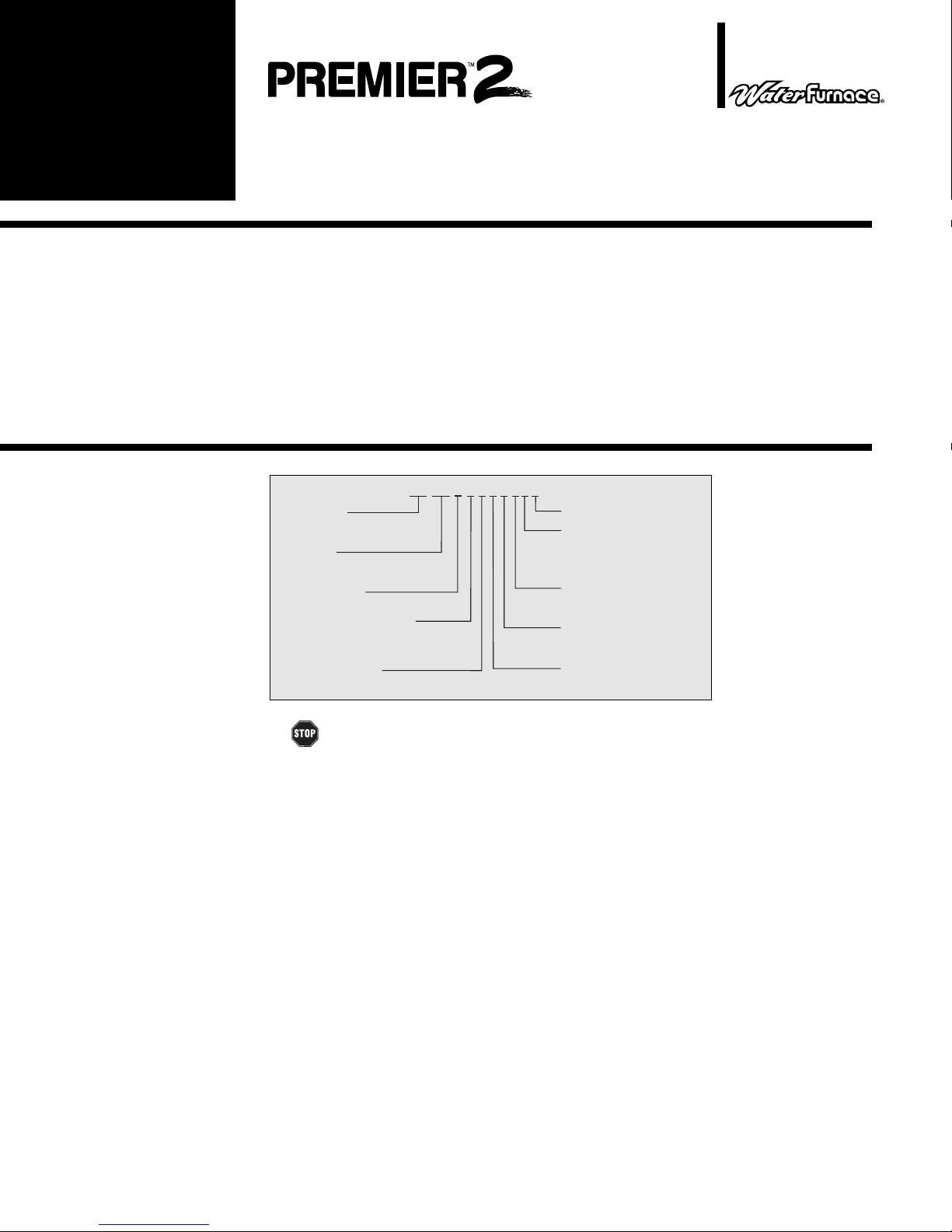
Model
Nomenclature
Geothermal System Single-Speed
Installation and Maintenance Manual
208-230/60/1 & 208-230/60/3
Model Nomenclature 1
Safety Considerations 1
Moving and Storage 1
Physical Data 2
General Installation Information 2-5
Closed Loop Cooler/Boiler Systems 5-6
Closed Loop Ground Source Systems 6-8
Open Loop Groundwater Systems 8-9
Desuperheater Connection 9-10
Initial Desuperheater Start Up 10-11
Electrical Connections 11-12
0
1
034
Model Type
ATV= Vertical Premier Unit
ATH= Horizontal Premier Unit
Unit Size
034 = 34,000 BTUH Nominal cooling at
90° F entering water
Design Vintage
C or higher = Premier2
Electrical Characteristics
0 = 208-230/60/1 Commercial
1 = 208-230/60/1 Residential
3 = 208-230/60/3 Commercial
Hot Water Options
0 = No hot water option
1 = Hot Water Generation w/pump
ATV
1
D
T
L
X
C
Wiring Schematics 13-16
Thermostats 17
Microprocessor Control Operation 17-19
Blower Speed 19
Blower Performance 20
Unit Start-Up 20-22
Preventive Maintenance 23
Troubleshooting 24
Replacement Procedures 24
Unit Operating Pressures 25
Unit Electrical Data 25
Non-Standard Options
Discharge Air Options
B = Bottom discharge (Vertical)
T = Top discharge (Vertical)
T = End discharge (Horizontal)
T = Side discharge (Horizontal)
Return Air Options
L = Left return
R = Right return
Coax Options
C = Copper
N = Cupronickel
For Future Use
Safety
Considerations
Moving and
Storage
WARNING: Before performing service or maintenance operations on a system,
turn off main power switches to the indoor unit. If applicable, turn off the accessory heater
power switch. Electrical shock could cause personal injury.
Installing and servicing heating and air conditioning equipment can be hazardous due to
system pressure and electrical components. Only trained and qualified service personnel should
install, repair or service heating and air conditioning equipment.
Untrained personnel can perform the basic maintenance functions of cleaning coils and
cleaning and replacing filters. All other operations should be performed by trained service
personnel. When working on heating and air conditioning equipment, observe precautions in the
literature, tags and labels attached to the unit and other safety precautions that may apply.
Follow all safety codes. Wear safety glasses and work gloves. Use a quenching cloth for
brazing operations and have a fire extinguisher available.
Move units in the normal “up” orientation as indicated by the arrows on each carton. Horizontal units may be moved and stored per the information on the carton. Do not stack more than
three units in total height. Vertical units may be stored one upon another to a maximum height of
two units. Do not attempt to move units while stacked. When the equipment is received, all items
should be carefully checked against the bill of lading to be sure all crates and cartons have been
received. Examine units for shipping damage, removing the units from the cartons if necessary.
Units in question should also be internally inspected. If any damage is noted, the carrier should
make the proper notation on the delivery receipt, acknowledging the damage.
PREMIER 2 SINGLE-SPEED INSTALLATION AND MAINTENANCE MANUAL
Physical Data
General
Installation
Information
MODEL
Fan Wheel
Fan Motor
Compressor
Air Coil: (Vertical)
Dimensions
Area (sq. ft.)
Rows
Air Coil: (Horizontal)
Dimensions
Area (sq. ft.)
Rows
R22 (oz.)
Filter-1" (Vertical)
Throwaway
Electrostatic
Filter-1" (Horizontal)
Throwaway
Electrostatic
Weight (lbs.)-Vertical
Weight (lbs.)-
* Optional 1 hp ECM2 fan motor available
Horizontal
AT019D
9 x 7
ECM2-1/2
Rotary
19 x 20
2.6
3
18 x 21
2.6
3
43.0
20 x 24
EAF2024
18 x 24
EAF1824
189
210
AT022C/D
9 x 7
ECM2-1/2
Rotary
24 x 20
3.3
3
18 x 27
3.4
3
58.0
24 x 24
EAF2424
2-18 x 18
EAF1836
252
256
AT028D AT034D
ECM2-1/2
24 x 20
18 x 27
9 x 7
Scroll
3.3
3
3.4
3
62.0
258
260
9 x 7
ECM2-1/2*
Scroll
27 x 20
3.8
3
18 x 30
3.8
3
65.0
2-14 x 24
EAF2428
2-18 x 18
EAF1836
274
270
AT046D
AT040D
11 x 10
ECM2-1/2*
11 x 10
ECM2-1/2*
Scroll
Scroll
28 x 25
28 x 25
4.9
4.9
3
3
20 x 35
20 x 35
4.9
4.9
3
2-14 x 30
EAF2830
EAF2037
88.0
336
339
3
85.0
1-20 x 12, 1-20 x 25
320
337
AT056D
11 x 10
ECM2-1
Scroll
32 x 25
5.6
3
20 x 40
5.6
3
116.0
2-10x30
1-12x30
EAF2042
1-18x20
1-24x20
EAF2042
399
429
AT066D
11 x 10
ECM2-1
Scroll
36 x 25
6.3
3
20 x 45
6.3
3
98.0
3-12x30
EAF2048
2-24x20
EAF2048
426
456
UNIT LOCATION
CAUTION:
45
°
-95°F and less than 75% relative humidity.
Locate the unit in an indoor area that allows for easy removal of the filter and access panels.
Location should have enough space for service personnel to perform maintenance or repair.
Provide sufficient room to make water, electrical and duct connection(s). If the unit is located in a
confined space, such as a closet, provisions must be made for return air to freely enter the space
by means of a louvered door, etc. Any access panel screws that would be difficult to remove
after the unit is installed should be removed prior to setting the unit. On horizontal units, allow
adequate room below the unit for a condensate drain trap and do not locate the unit above
supply piping. These units are not approved for outdoor installation and, therefore, must be
installed inside the structure being conditioned.
Do not locate in areas where ambient conditions are not maintained within
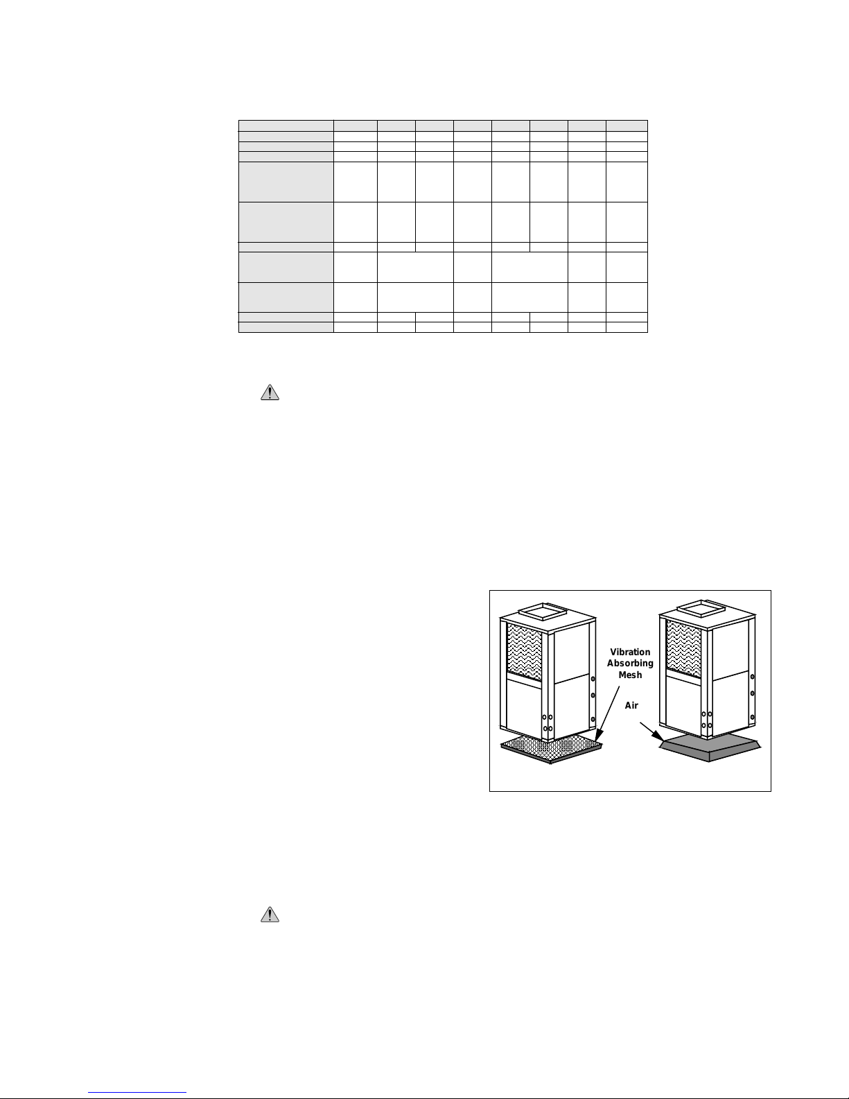
SETTING VERTICAL UNITS
Vertical units are available in left or
right air return configurations. Top flow
vertical units should be mounted level on a
vibration absorbing pad slightly larger than
the base to provide isolation between the
unit and the floor. It is not necessary to
Vibration
Absorbing
Mesh
Air
Pad
anchor the unit to the floor (see Figure 1).
Bottom flow units should be mounted level
and well sealed to the floor to prevent
air leakage.
NOTE:
If access to the left side of the
Figure 1 – Vertical Unit Mounting
unit will be limited after installation, remove the two mounting screws on the left side of the
control box before setting the unit (leave the two front mounting screws intact). This will allow the
control box to be removed with only the two front mounting screws for future service.
SETTING HORIZONTAL UNITS
CAUTION:
enough to support the unit. The rods must be securely anchored to the ceiling.
Horizontal units are available with side or end discharge and may be field converted from one
to the other by replacing the discharge panel (TB920813) with a new panel which must be
ordered separately. Horizontal units are normally suspended from a ceiling by four 3/8” diameter
threaded rods (six on ATH040-066). The rods are usually attached to the unit by hanger bracket
kits furnished with each unit.
Do not use rods smaller than 3/8” diameter since they may not be strong
2
PREMIER 2 SINGLE-SPEED INSTALLATION AND MAINTENANCE MANUAL
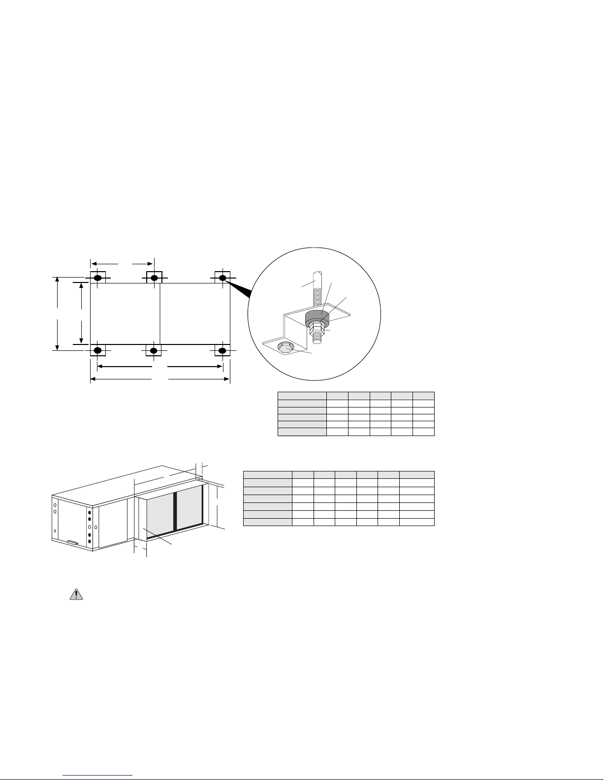
Lay out the threaded rods per the dimensions in Figure 2. Assemble the hangers to the unit
as shown. Securely tighten the brackets to the unit using the weld nuts located on the underside
of the bottom panel. When attaching the hanger rods to the bracket, a double nut is recommended since vibration could loosen a single nut. The unit should be pitched approximately
1/4” towards the drain in both directions to facilitate the removal of condensate. (see Figure
5A on page 5). Use only the bolts provided in the kit. The use of longer bolts could damage
internal parts.
Some residential applications require the installation of horizontal units on an attic floor. In
this case, the unit should be set in a full size secondary drain pan on top of a vibration absorbing
mesh. The secondary drain pan prevents possible condensate overflow or water leakage
damage to the ceiling. The secondary drain pan is usually placed on a plywood base isolated
from the ceiling joists by additional layers of vibration absorbing mesh.
Figure 2– Hanger Location and Assembly
E
3/8" Threaded Rod
C
Compressor
Section
A
Air Handler
Section
B
D
(not supplied)
ATH019
ATH022, 028, 34
ATH040, 046
ATH056
ATH066
MODEL
Vibrator
Isolator
Hex Nuts
(not supplied)
Bolt and
Lockwasher
A
24.8
24.8
27.8
27.8
27.8
Washer
51.5
61.5
70.5
75.5
80.5
22.5
22.5
25.5
25.5
25.5
CB
DE
53.0
63.0
29.9
72.0
29.9
77.0
29.9
82.0
-
-
Figure 3– Optional Filter Rack
C
A
Horizontal Filter Rack
MODEL
ATH019
D
ATH022, 028
ATH034
B
ATH040, 046
ATH056
ATH066
A
24.5
36.1
36.1
37.1
42.1
47.1
18.1
18.1
18.1
20.1
20.1
20.1
CB
D E Model No.
0.5
2.5
0.5
2.0
0.5
2.0
0.6
2.2
0.6
2.2
0.6
2.2
5.5
5.5
5.5
5.5
5.5
5.5
DCH1824
DCH1836
DCH1836
DCH2037
DCH2042
DCH2048
1" duct connection is provided.
E
Door side mountable
on either end
Construction is air tight.
DUCT SYSTEM
CAUTION:
ing ductwork.
An air outlet collar is provided on vertical top flow units and all horizontal units to facilitate a
duct connection (vertical bottom flow units have no collar). A flexible connector is recommended
for discharge and return air duct connections on metal duct systems. Uninsulated duct should be
insulated with a minimum of 1" duct insulation. Application of the unit to uninsulated ductwork in
an unconditioned space is not recommended as the unit’s performance will be adversely affected.
For vertical bottom flow units, cut the floor opening for air discharge at least 1/2" larger than
the unit air outlet. Protect opening edges in combustible flooring with a sheet metal
overwrap. Discharge air only into a suitable supply duct system and do not locate
registers or openings directly under unit air outlet.
Be sure to remove the shipping material from the blower throat before connect-
3
PREMIER 2 SINGLE-SPEED INSTALLATION AND MAINTENANCE MANUAL
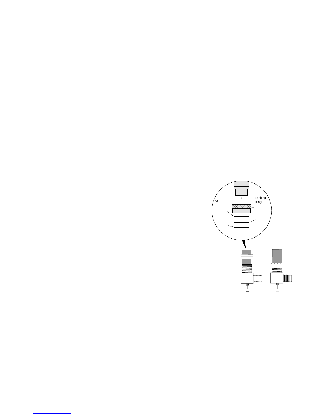
Locking
Ring
Stainless
Steel
Snap Ring
Gasket
Support
Sleeve
Gasket
Material
If the unit is connected to existing ductwork, check the duct system to ensure that it has the
capacity to accommodate the air required for the unit application. If the duct is too small, as in
the replacement of heating only systems, larger ductwork should be installed. All existing
ductwork should be checked for leaks and repairs.
The duct system should be sized to handle the design airflow quietly. Due to increased run
time at lower airflows, the Premier 2 diffusers should be sized for 75% of design airflow. To
maximize sound attenuation of the unit blower, the supply and return plenums should
include an internal duct liner of fiberglass or constructed of ductboard for the first few
feet. If air noise or excessive airflow is a problem, the blower speed can be changed (see the
Blower Speed and Blower Performance sections on pages 19 and 20).
WATER PIPING
All Residential Premier 2 source water connections are swivel piping fittings that accept a 1"
male pipe thread (MPT) (see Figure 4A). The swivel connector has a rubber gasket seal similar
to a rubber hose gasket, which when mated to the flush end of any 1" threaded pipe provides a
leak-free seal without the need for thread sealing tape or compound. Check to ensure that the
rubber seal is in the swivel connector prior to attempting any connection. The rubber
seals are shipped attached to the air coil inside the blower compartment.
To make the connection to a ground loop system, mate the brass connector (supplied in
CK4L and CK4S connector kits) against the
rubber gasket in the swivel connector and
thread the female locking ring onto the pipe
threads, while maintaining the brass
connector in the desired direction (see
Figure 4B). Tighten the connectors by
hand, then gently snug the fitting with pliers
to provide a leak-proof joint. When connecting to an open loop (groundwater) system,
thread any 1" MPT fitting (PVC or copper)
into the swivel connector and tighten in the
same manner as noted above. The open
and closed loop piping system should
include pressure/temperature taps for
serviceability.
Never use flexible hoses smaller
than 1" inside diameter on the unit.
Limit hose length to 10 ft. per connection. Check carefully for water leaks.
Figure 4A
Figure 4B - The female
locking ring is threaded
onto the pipe threads which
holds the male pipe end
against the gasket and seals
the joint.
WATER QUALITY
The unit may be ordered with either a copper or a cupronickel coaxial heat exchanger.
Copper is adequate for closed loop and open loop groundwater systems which are not high in
mineral content. In conditions anticipating moderate scale formation or in brackish water, a
cupronickel heat exchanger is recommended. In groundwater situations where scaling could be
heavy or where biological growth such as iron bacteria will be present, a closed loop system is
recommended. The heat exchanger coils in groundwater systems may over a period of time lose
heat exchange capabilities due to a buildup of mineral deposits inside. These can be cleaned,
but only by a qualified service mechanic as acid and special pumping equipment are required.
4
Desuperheater coils can likewise become scaled and possibly plugged. In areas with
extremely hard water, the owner should be informed that the heat exchanger may require
occasional acid flushing.
PREMIER 2 SINGLE-SPEED INSTALLATION AND MAINTENANCE MANUAL
FREEZE PROTECTION
Set the freeze protection switch SW2-2 on the printed circuit board for applications using a
closed loop antifreeze solution to "LOOP". On applications using an open loop/groundwater
system, set to "WELL" (the factory setting).
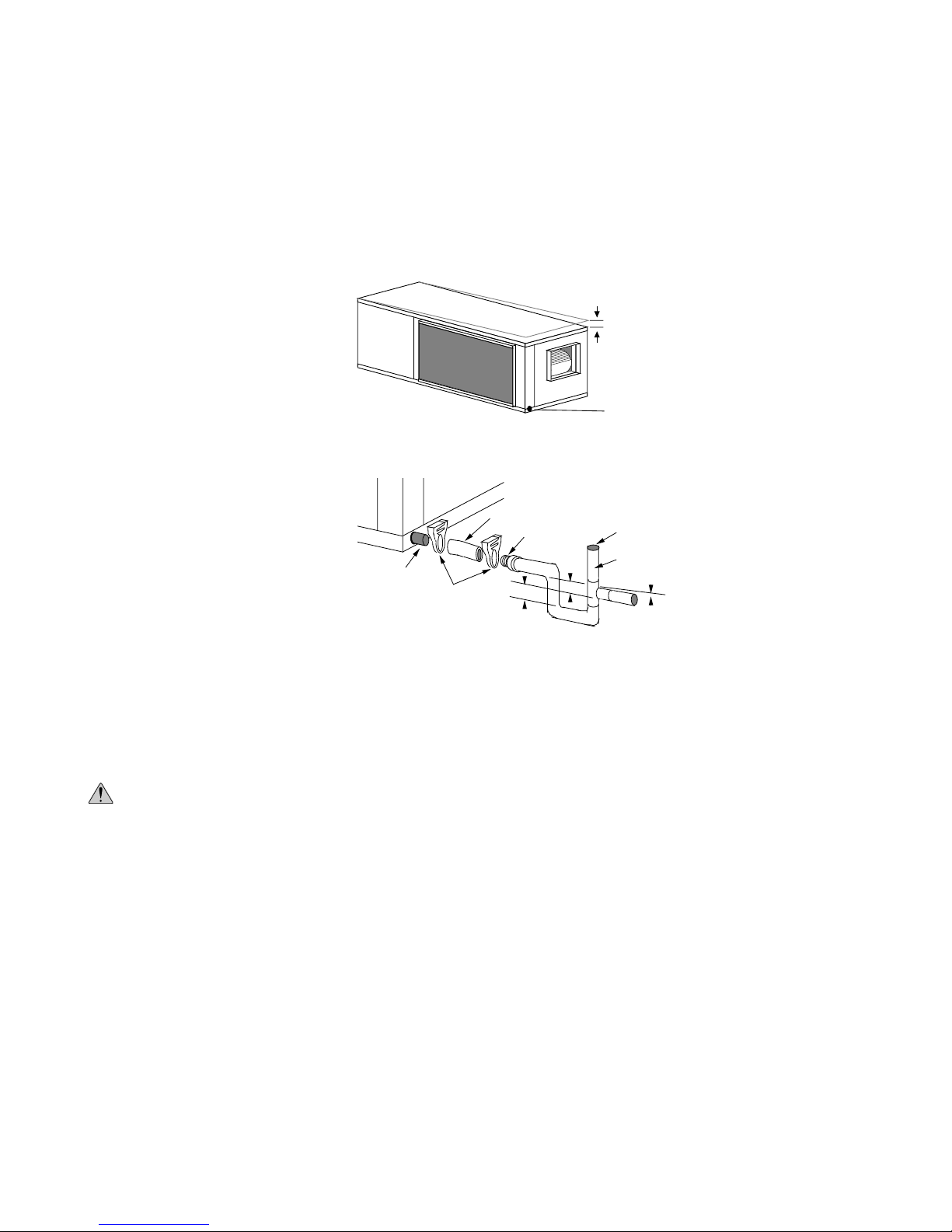
CONDENSATE DRAIN
On vertical units, the internal
condensate drain assembly consists of a
drain tube which is connected to the
drain pan, a 3/4" PVC female adapter
and a flexible connecting hose. The
female adapter may exit either the front
or the side of the cabinet. The adapter
should be glued to the field-installed
PVC condensate piping. On vertical
units, a condensate hose is inside all
cabinets as a trapping loop; therefore,
an external trap is not necessary. On
horizontal units, a copper stub is
provided for condensate drain piping
connection. An external trap is required
(see Figure 5B). If a vent is necessary,
an open stand pipe may be applied to a
tee in the field-installed condensate
piping.
Figure 5A - Unit Pitch for Drain
Figure 5B - Horizontal Drain Connection
Clear PVC Hose *
3/4" Barb to
Glue Adapter *
Copper Tube Stub
Plastic Hose Clamp *
*Included with unit
1.5"
1.5"
1/4'' Pitch
Drain
Vent (if needed)
3/4" PVC
1/8" per foot
AIR COIL
To obtain maximum performance, the air coil should be cleaned before start-up. A 10 percent
solution of dishwasher detergent and water is recommended for both sides of the coil; a thorough
water rinse should follow.
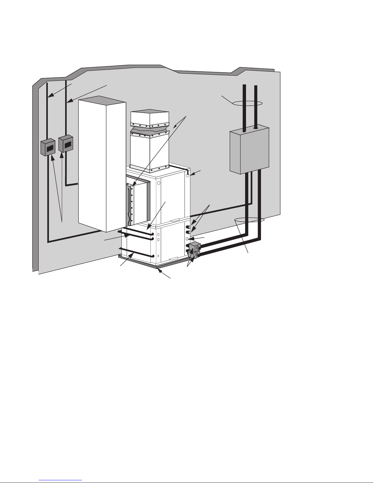
COOLER/BOILER
CAUTION:
The water loop is usually maintained between 60°F and 90°F (Premier 2 units allow 25°F 110°F EWT) for proper heating and cooling operation. This is accomplished with a cooling tower
and a boiler (see Figure 6). To reject excess heat from the water loop, use a closed circuit
evaporative cooler or an open type cooling tower with a secondary heat exchanger between the
tower and the water loop. If an open type cooling tower is used without a secondary heat
exchanger, continuous chemical treatment and filtering of the water must be performed to ensure
the water is free from damaging materials. The water lines should be routed so as not to interfere
with access to the unit. Flexible hose connections should be used to minimize vibration transmission.
Before final connection to the unit, the supply and return hose kits must be connected
together and the system flushed to remove dirt, piping chips and other foreign material. Normally,
a combination balancing and close-off (ball) valve is installed at the return and a rated gate or
ball valve is installed at the supply. The return valve can be adjusted to obtain the proper water
flow. The valves allow the unit to be removed for servicing.
Water piping exposed to outside temperatures may be subject to freezing
Closed Loop
.
Cooler/Boiler
Systems
5

Figure 6 - Closed Loop—Cooler/Boiler System
PREMIER 2 SINGLE-SPEED INSTALLATION AND MAINTENANCE MANUAL
Electric heat
assembly
(optional)
Flexible Duct
Collar
Insulate supply
plenum and use at
least a 90° elbow
to reduce noise
3/8”
Threaded rods (6)
To Thermostat
P/T Plugs
Hose Kits
Ball Valves
Cooler/Boiler Loop
Disconnects
To Line
Power
Line Voltage
Hanging
Brackets
(included)
The proper water flow must be assured to each unit whenever the unit operates. To assure
proper flow, use pressure/temperature ports to determine the flow rate. These ports should be
located adjacent to the supply and return connections on the unit. The proper flow rate cannot be
accurately set without measuring the water pressure drop through the refrigerant-to-water heat
exchanger (circuit setters may also be used). See Table 2 on page 22 for water flow and
pressure drop information.
NOTE:
For boiler/cooling tower systems with no antifreeze solution, set SW2-2 to the
"WELL" position.
Closed Loop
Ground
Source
Systems
GROUND SOURCE SYSTEMS
NOTE:
position.
Once piping is completed between the unit, flow center and the ground loop (see Figure 7
on page 7), final purging and charging of the loop is required. A WaterFurnace flush cart (or a 1.5
HP pump minimum) is needed to achieve adequate flow velocity in the loop to purge air and dirt
particles from the loop itself. Antifreeze solution is used in most areas to prevent freezing. Flush
the system adequately to remove as much air as possible then pressurize the loop to a static
pressure of 50-75 psi (winter) or 40-50 psi (summer). This is normally adequate for good system
operation. Loop static pressure will fluctuate with the seasons. Pressures will be higher in the
winter months than during the cooling season. This fluctuation is normal and should be
considered when initially charging the system.
6
For closed loop systems with antifreeze protection, set SW2-2 to the "LOOP"
PREMIER 2 SINGLE-SPEED INSTALLATION AND MAINTENANCE MANUAL
Figure 7- Closed Loop: Ground Source Application - Single unit with Flow Center
Unit Supply
Disconnects
(If Applicable)
External
Pump Power
Auxiliary Heat
Supply
Unit Power
GEOLINK
Polyethylene w/
Armaflex
Insulation
Flexible Duct Collar
Desuperheater
Connections
®
®
Auxiliary
Heater
Knockout
Drain
TO
LOOP
GEOLINK
Flow
Centre*
®
* For complete
Geolink Flow
Center installation
information refer
to WF P/N
96P090A01
WF Ground Loop Connector
Low
Voltage to
Thermostat
P/T Plugs
Vibration Absorbing Pad
Kits with Armaflex
(CK4S or CK4L)
After pressurization, be sure to remove the plug in the end of the loop pump motor(s) (if
applicable) to allow trapped air to be discharged and to ensure that the motor housing has been
flooded. Ensure that the loop flow center provides adequate flow through the unit by checking the
pressure drop across the heat exchanger and comparing it to the figures shown in Table 2 on
page 22. Usually 2.5 to 3 gpm of flow per ton of cooling capacity is recommended in earth loop
applications. See Figures 4A and 4B on page 12 for loop pump power wiring details.
MULTIPLE UNITS ON ONE FLOW CENTER
When two Premier 2 units are connected to one loop pumping system, pump control is
automatically achieved by connecting the slave terminals on connector P2 in both units with 2wire thermostat wire. These terminals are polarity conscious (see Figure 8 on page 8). The loop
pump(s) may be powered from either Premier 2 unit, whichever is more convenient. If either unit
calls, the loop pump(s) will automatically start. The use of two units on one flow center is
generally limited to a total of six tons of unit capcity.
®
7

Figure 8- Premier 2 Slave Hook-up
PREMIER 2 SINGLE-SPEED INSTALLATION AND MAINTENANCE MANUAL
Premier 2 Unit #1
Shut
CC
Down
With pump
wired to
Unit 1
Shut
Down
CC
SL1InSL1
Premier 2 Unit #2
Two Premier 2 units
Open Loop
Groundwater
Systems
SL1InSL1
Out
Not
Out
Used
Not
Not
Used
Used
With pump
wired to
Unit 2
Not
Used
Premier 2 Unit #1
Not
Used
SL1InSL1
Out
SLG
SL
Shut
CC
Down
With pump
wired to Unit 1
GL1
Not
Used
Premier or Spectra Unit #2
One Premier 2 unit and one
Premier AT or Spectra unit
(with optional circut board)
Not
Not
Used
Used
With pump
wired to
Unit 2
SX unit
12345678
Normally Open
Contacts
Coil
C SL1 IN
Premier 2 Unit Low Voltage
Wiring Legend
Low Voltage
High Voltage
One Premier 2 unit
and one Spectra
electro-mechanical unit
24v
Premier
High
Voltage
PB1
L 1
L 2
OPEN LOOP SYSTEMS
NOTE:
For open loop/groundwater systems or systems that do not contain an antifreeze
solution, set SW2-2 to the WELL position.
Typical open loop piping is shown below in Figure 9. Always maintain water pressure in
the heat exchanger by placing water control valves at the outlet of the unit to prevent mineral
precipitation. Use a closed, bladder-type expansion tank to minimize mineral formation due to air
exposure. Ensure proper water flow through the unit by checking pressure drop across the heat
exchanger and comparing it to the figures in Table 2 on page 22. Normally, about 2 gpm flow rate
per ton of cooling capacity (1.5 gpm per ton minimum at 50°F) is needed in open loop systems.
FC 1 or FC 2
Flow Center
240v
pump
Figure 9 - Open System: Groundwater Application
Auxiliary Heat Supply
Unit Supply
Flexible Duct Collar
Rubber Bladder
Expansion Tank
Auxiliary
Heater
Knockout
Flow Control
Disconnects
(If Applicable)
Low Voltage
to Thermostat and
8
Valve
Vibration Absorbing Pad
Unit Power
P/T Plugs
Desuperheater
Connections
Drain
Strainer
Boiler Drains
For HX Flushing
Solenoid Valve
Valve
(on oulet of
solenoid
valve)
Water Out
Water In
Shut-Off
Valves
Shut-Off Valve
(to isolate solenoid
valve while acid
flushing)
PREMIER 2 SINGLE-SPEED INSTALLATION AND MAINTENANCE MANUAL
Typical external 24V
C
R
2
1
P1
Solenoid
P3
123
Acc Com
Acc NC
Acc NO
Discharge water from the unit is not contaminated in any manner and can be disposed of in
various ways, depending on local building codes (e.g. recharge well, storm sewer, drain field,
adjacent stream or pond, etc.) Most local codes forbid using the sanitary sewer for disposal.
Consult your local building and zoning department to assure compliance in your area.
Figure 10 - The water control
solenoid is wired between the common
pin #2 connector P1 and pin #3
connector P3, and a jumper wire is
water solenoid valves (type PPV100,
BPV100) wiring
Note: switch SW2 - 3 to comp position
connected between R and pin #1
connector P3. Notice that DIP switch
2–3, located on the PCB, must be
switched to the “Comp” position so the
valve will operate with the compressor.
Valve
WATER TANK PREPARATION
A family of four should have a water heater with approximately a 50-gallon capacity. For
families of more than four, use an 80-gallon water heater or two 50-gallon water heaters connected in a series as shown in Figure 13. Electric water heaters are recommended.
Steps:
1) Turn off the power to the water heater. Elements will burn out if energized dry!
2) Attach a water hose to the water tank drain connection and run the other end of the hose to
an open drain or outdoors.
3) Close the cold water inlet valve to the water heater tank.
4) Drain the tank by opening the valve on the bottom of the tank, then open the pressure relief
valve or hot water faucet.
5) Flush the tank by opening the cold water inlet valve to the water heater to free the tank of
sediments. Close when draining water is clear.
6) Disconnect the garden hose and remove the drain valve from the water heater.
Desuperheater
Connection
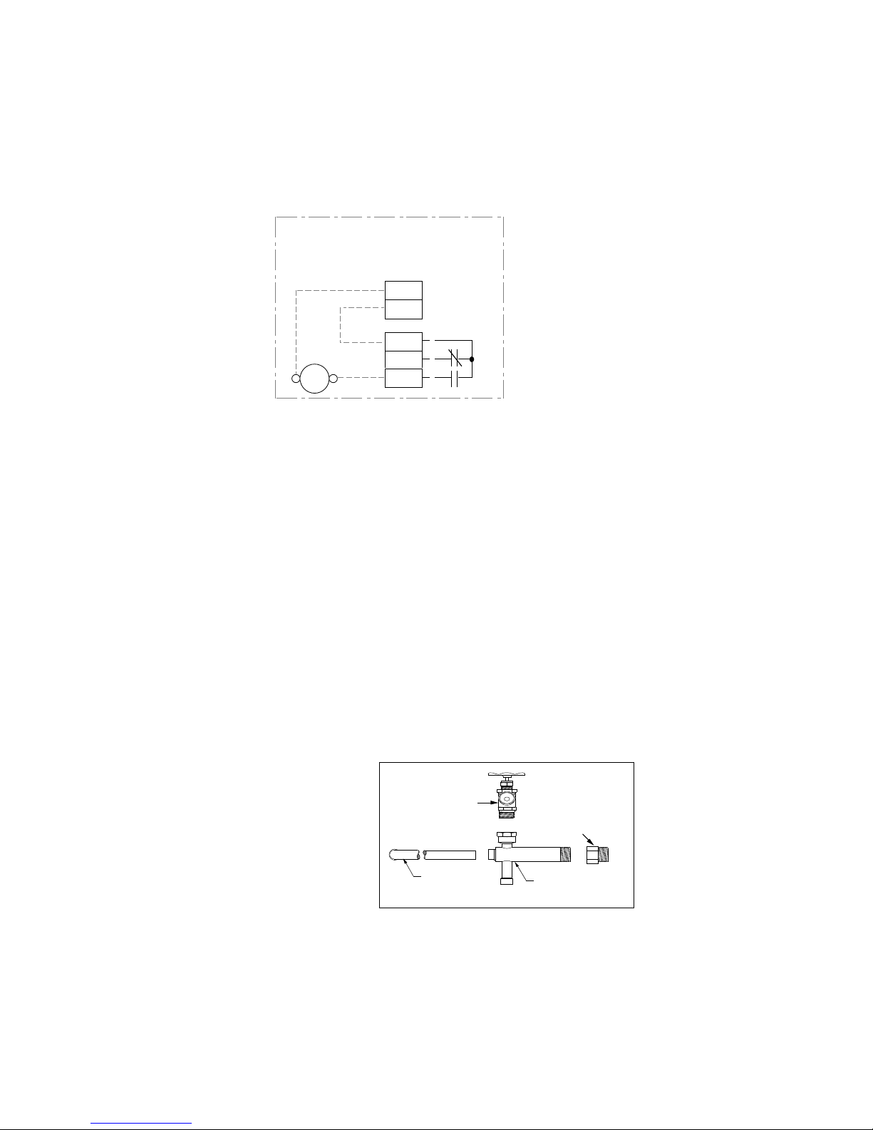
PLUMBING INSTALLATION
Steps:
1) Thread the male end of the coaxial drain tee
into the water heater drain port (see Figure 11.
2) Solder the 1/2" copper elbow into the coaxial
drain tee with the 90° bend pointing in the
correct direction.
3) Install the drain valve on the drain tee
assembly.
4) Run interconnection copper tubing (1/2”
nominal). The recommended maximum
distance is 50 ft. between the unit and water
heater (see Figures 12 and 13).
5) To prevent air entrapment in the system, install
a vent coupling at the highest point of the interconnecting line.
6) Insulate all exposed surfaces of both connecting water lines with 3/8" wall closed
cell insulation.
Figure 11 - Water Heater Connection Kit
DRAIN VALVE
BRASS ADAPTER
1/2
NOMINAL
LONG
ELBOW
The optional brass adapter is available for use in areas
where local plumbing codes require it.
COAXIAL DRAIN TEE
9
 Loading...