

Page 1
700A11
Geothermal Heat Pump - 50Hz
• R-410A Refrigerant
• 009, 012, 015 kW Variable Speed
Installation Information
Water Piping Connections
Hot Water Generator Connections
Electrical
Startup Procedures
Troubleshooting
Preventive Maintenance
7 Series 50Hz 700A11 Installation Manual
CUS
IM2705AN 01/15
Page 2

Page 3

Table of Contents
Model Nomenclature. . . . . . . . . . . . . . . . . . . . . . . . . . . . . . . . . . . . . . . . . . . . . . . . . . . . . . . . . . . . . . . 4
General Installation Information . . . . . . . . . . . . . . . . . . . . . . . . . . . . . . . . . . . . . . . . . . . . . . . . . . . . . 5
Closed Loop Ground Source Systems . . . . . . . . . . . . . . . . . . . . . . . . . . . . . . . . . . . . . . . . . . . . . . . . 9
Open Loop Ground Water Systems . . . . . . . . . . . . . . . . . . . . . . . . . . . . . . . . . . . . . . . . . . . . . . . . . 10
Hot Water Generator Connections. . . . . . . . . . . . . . . . . . . . . . . . . . . . . . . . . . . . . . . . . . . . . . . . . . . 11
Electrical Connections . . . . . . . . . . . . . . . . . . . . . . . . . . . . . . . . . . . . . . . . . . . . . . . . . . . . . . . . . . . . .13
Electronic Thermostat Installation . . . . . . . . . . . . . . . . . . . . . . . . . . . . . . . . . . . . . . . . . . . . . . . . . . 14
Auxiliary Heat Ratings . . . . . . . . . . . . . . . . . . . . . . . . . . . . . . . . . . . . . . . . . . . . . . . . . . . . . . . . . . . . .15
Auxiliary Heat Electrical Data . . . . . . . . . . . . . . . . . . . . . . . . . . . . . . . . . . . . . . . . . . . . . . . . . . . . . . .15
Electrical Data . . . . . . . . . . . . . . . . . . . . . . . . . . . . . . . . . . . . . . . . . . . . . . . . . . . . . . . . . . . . . . . . . . . .15
7 SERIES 700A11 INSTALLATION MANUAL
Blower Performance Data . . . . . . . . . . . . . . . . . . . . . . . . . . . . . . . . . . . . . . . . . . . . . . . . . . . . . . . . . 16
Dimensional Data. . . . . . . . . . . . . . . . . . . . . . . . . . . . . . . . . . . . . . . . . . . . . . . . . . . . . . . . . . . . . . . . . .17
Physical Data . . . . . . . . . . . . . . . . . . . . . . . . . . . . . . . . . . . . . . . . . . . . . . . . . . . . . . . . . . . . . . . . . . . . .21
The Aurora™ Advanced VS Control System . . . . . . . . . . . . . . . . . . . . . . . . . . . . . . . . . . . . . . . . . . 22
Operation Logic . . . . . . . . . . . . . . . . . . . . . . . . . . . . . . . . . . . . . . . . . . . . . . . . . . . . . . . . . . . . . . . . . . .31
Wiring Schematics. . . . . . . . . . . . . . . . . . . . . . . . . . . . . . . . . . . . . . . . . . . . . . . . . . . . . . . . . . . . . . . . 32
Unit Startup. . . . . . . . . . . . . . . . . . . . . . . . . . . . . . . . . . . . . . . . . . . . . . . . . . . . . . . . . . . . . . . . . . . . . . 36
Pressure Drop . . . . . . . . . . . . . . . . . . . . . . . . . . . . . . . . . . . . . . . . . . . . . . . . . . . . . . . . . . . . . . . . . . . . 38
Compressor and Thermistor Resistance . . . . . . . . . . . . . . . . . . . . . . . . . . . . . . . . . . . . . . . . . . . . . 38
Refrigerant Circuit Guideline . . . . . . . . . . . . . . . . . . . . . . . . . . . . . . . . . . . . . . . . . . . . . . . . . . . . . . . 39
Heat of Extraction/Rejection. . . . . . . . . . . . . . . . . . . . . . . . . . . . . . . . . . . . . . . . . . . . . . . . . . . . . . . 39
Operating Parameters. . . . . . . . . . . . . . . . . . . . . . . . . . . . . . . . . . . . . . . . . . . . . . . . . . . . . . . . . . . . . 40
Reference Calculations and Legend. . . . . . . . . . . . . . . . . . . . . . . . . . . . . . . . . . . . . . . . . . . . . . . . . 41
Troubleshooting . . . . . . . . . . . . . . . . . . . . . . . . . . . . . . . . . . . . . . . . . . . . . . . . . . . . . . . . . . . . . . . . . . 41
Preventive Maintenance and Replacement Procedures. . . . . . . . . . . . . . . . . . . . . . . . . . . . . . . . 45
Service Parts List . . . . . . . . . . . . . . . . . . . . . . . . . . . . . . . . . . . . . . . . . . . . . . . . . . . . . . . . . . . . . . . . . 46
Page 4
7 SERIES 50Hz 700A11 INSTALLATION MANUAL
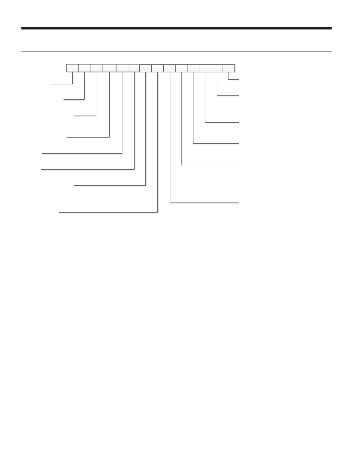
N
1 2-3 4 5-7 8 9 10
11 12 13 15
VK V 012 * 6 1 1 C T L 014J16N
17
Model Nomenclature
Model Type
N – 7 Series Water-to-Air
Compressor Type
VK – Variable Speed
Cabinet Configuration
V – Vertical
H - Horizontal
Unit Capacity (kW)
009, 012, 015
Vintage
* - Factory Use Only
Voltage
6 – 220-240/50/1
Hot Water Generation
0 – No Hot Water Generation
1 – Hot Water Generation with
Factory Installed Pump
Blower Options
1 – Variable Speed ECM
2 – High Static Variable Speed ECM
(009 Only)
Future Option
N - None
Control Option
J – Aurora
K – Aurora Variable Speed Control with
Performance Monitoring
Filter Option
0 – 5.08cm MERV11 Filter
1 – AlpinePure 411 (Vertical Only)
Return Air Configuration
L – Left
R – Right
Discharge Air Configuration
T – Top (Vertical)
B – Bottom (Vertical)
R – Rear (Vertical)
S – Side (Horizontal)
E – End (Horizontal)
Water Coil Option
C – Copper
N – CuproNickel
Rev.: 17 July 2013D
TM
Variable Speed Control
4
Page 5
General Installation Information
7 SERIES 50Hz 700A11 INSTALLATION MANUAL
Safety Considerations
WARNING: Before performing service or
maintenance operations on a system, turn off main
power switches to the indoor unit. If applicable,
turn off the accessory heater power switch.
Electrical shock could cause personal injury.
Installing and servicing heating and air conditioning
equipment can be hazardous due to system pressure and
electrical components. Only trained and qualified service
personnel should install, repair or service heating and air
conditioning equipment. Untrained personnel can perform
the basic maintenance functions of cleaning coils and
cleaning and replacing filters. All other operations should
be performed by trained service personnel. When working
on heating and air conditioning equipment, observe
precautions in the literature, tags and labels attached to the
unit and other safety precautions that may apply.
Follow all safety codes. Wear safety glasses and work
gloves. Use a quenching cloth for brazing operations and
have a fire extinguisher available.
Moving and Storage
Move units in the normal “up” orientation. Horizontal units
may be moved and stored per the information on the
packaging. Do not stack more than three units in total
height. Vertical units may be stored one upon another to
a maximum height of two units. Do not attempt to move
units while stacked. When the equipment is received, all
items should be carefully checked against the bill of lading
to be sure all crates and cartons have been received.
Examine units for shipping damage, removing the units
from the packaging if necessary. Units in question should
also be internally inspected. If any damage is noted, the
carrier should make the proper notation on the delivery
receipt, acknowledging the damage.
locate the unit above supply piping. Care should be taken
when units are located in unconditioned spaces to prevent
damage from frozen water lines and excessive heat that
could damage electrical components.
Filter Rack Conversion
A 50.8mm MERV 11 filter is shipped with the heat pump.
To field convert the filter rack to use 25.4mm filters, simply
insert the provided plastic push pins into the holes located
in the filter rack. There are holes on the top and bottom
of the rack, underneath the instruction labels, for field
conversion to 25.4mm filters.
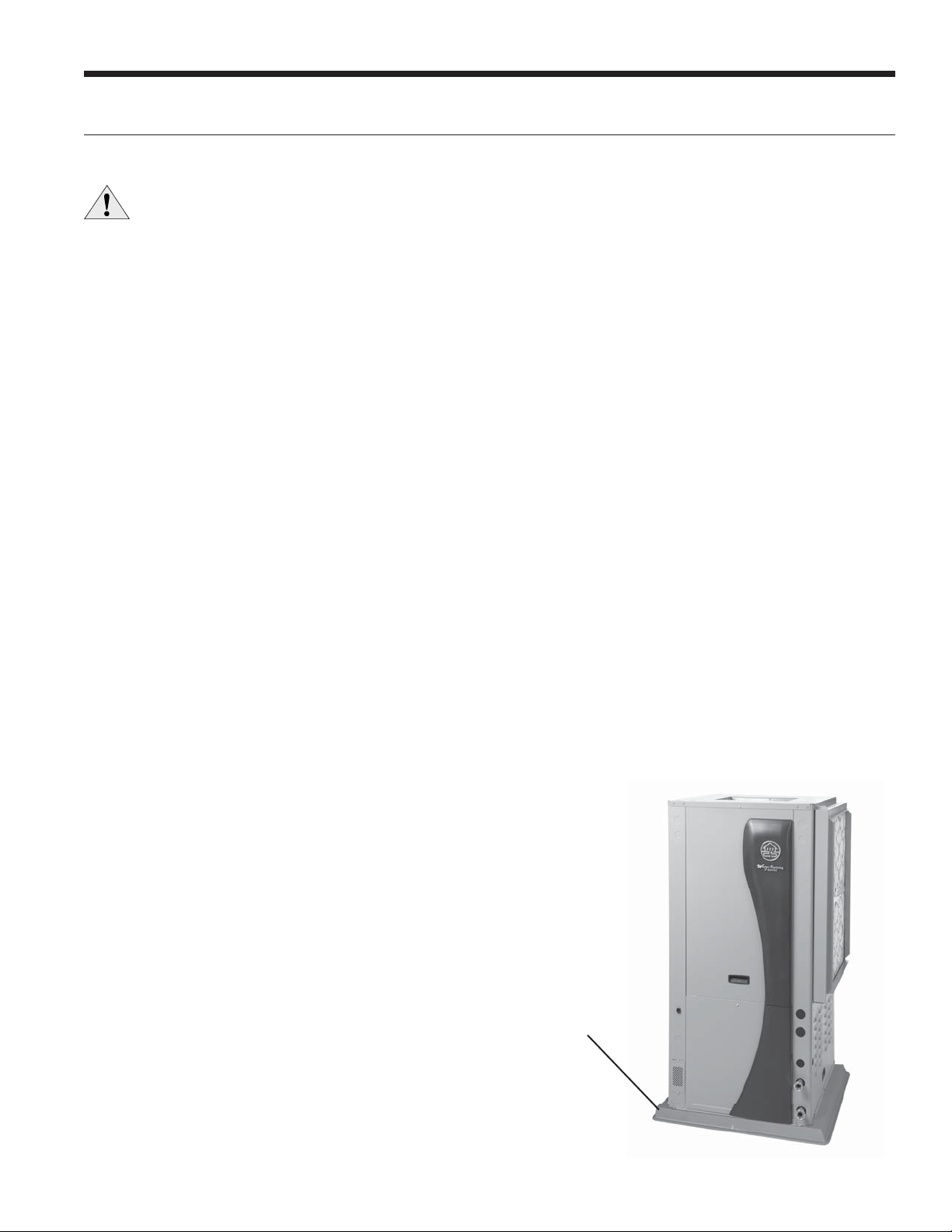
Installing Vertical Units
Prior to setting the unit in place, remove and discard the
compressor hold down shipping bolt located at the front of
the compressor mounting bracket.
Vertical units are available in left or right air return
configurations. Top and rear air discharge vertical units
should be mounted level on a vibration absorbing pad
slightly larger than the base to provide isolation between
the unit and the floor. It is not necessary to anchor the unit
to the floor (see below).
Bottomflow units should be mounted level and sealed well
to floor to prevent air leakage. Bottomflow units require
the supply air opening to be cut at least 12.7mm larger
than the unit’s air outlet. Protect the edges of combustible
flooring with sheet metal over-wrap or other noncombustible material.
Figure 1: Vertical Unit Mounting
Unit Location
Locate the unit in an indoor area, minimum ambient of
7.2°C and maximum ambient of 37.8°C, that allows for easy
removal of the filter and access panels. Attic installations
are not approved and could result in loss of warranty.
Installation is not recommended in areas with excessive dirt
and debris as this may be drawn into the VS drive causing
overheating of the VS drive. Location should have enough
space for service personnel to perform maintenance or
repair. Provide sufficient room to make water, electrical
and duct connection(s). If the unit is located in a confined
space, such as a closet, provisions must be made for return
air to freely enter the space by means of a louvered door,
etc. Any access panel screws that would be difficult to
remove after the unit is installed should be removed prior
to setting the unit. On horizontal units, allow adequate
room below the unit for a condensate drain trap and do not
50.8mm Extruded
Polystyrene
5
Page 6
7 SERIES 50Hz 700A11 INSTALLATION MANUAL
General Installation Information cont.
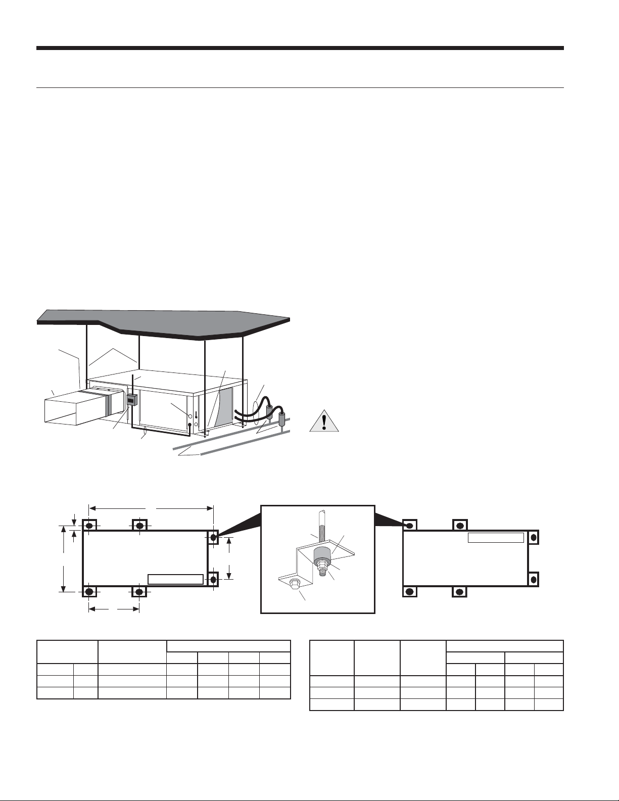
Installing Horizontal Units
Remove and discard the compressor hold down shipping
bolt located at the front of the compressor mounting
bracket prior to setting the unit in place. Horizontal units
are available with side or end discharge. Horizontal units
are normally suspended from a ceiling by four or six 9.5mm
diameter threaded rods. The rods are usually attached to
the unit by hanger bracket kits furnished with each unit.
Lay out the threaded rods per the dimensions in Figure
3. Assemble the hangers to the unit as shown. Securely
tighten the brackets to the unit using the weld nuts located
on the underside of the bottom panel. When attaching the
hanger rods to the bracket, a double nut is required since
Figure 2: Horizontal Unit Mounting
O
Threaded Rods
Electrical
Disconnect
To Line
Power
To
Thermostat
Line Voltage
Building Water Loop
Hanging
Brackets
(Included)
Ball Valves
Hose
Kits
Flexible Duct
Collar
Insulate supply
plenum and use
at least one 90
elbow to
reduce noise
vibration could loosen a single nut. To allow filter access,
one bracket on the filter side should be installed 180° from
the position shown in Figure 3. The unit should be pitched
approximately 6.35mm towards the drain in both directions
to facilitate the removal of condensate. Use only the bolts
provided in the kit to attach hanger brackets. The use of
longer bolts could damage internal parts.
Some residential applications require the installation of
horizontal units on an attic floor. In this case, the unit
should be set in a full size secondary drain pan on top of a
vibration absorbing pad. The secondary drain pan prevents
possible condensate overflow or water leakage damage to
the ceiling. The secondary drain pan is usually placed on a
plywood base isolated from the ceiling joists by additional
layers of vibration absorbing material.
SPECIAL NOTE: The VS drive is limited to a maximum of
51.7°C ambient temperature. For this reason the 7 Series
is not approved for attic installations. The compressor
compartment temperature is also monitored by the
Aurora. This ‘compressor ambient’ temperature is available
on the AID Tool for reading. The control will de-rate the
compressor when ambient air is above 51.7°C. Installing this
product in an attic could result in loss of warranty.
CAUTION: Do not use rods smaller than 9.5mm
diameter since they may not be strong enough
to support the unit. The rods must be securely
anchored to the ceiling.
Figure 3: Hanger Location and Assembly
4
0
2
/
!
"
/W`1]WZ
Hanger Dimensions
Unit Hanger Dimensions
ABCD
009
012
015
Model
Hanger Kit Part
Number
cm. 99S500A03 196.6 70.6 61.2 74.4
cm. 99S500A03 196.6 70.6 61.2 74.4
cm. 99S500A03 209.3 70.6 61.2 74.4
:STb@WUVb
!&BV`SORSR
@]RPg]bVS`a
1
0]ZbO\R
:]QYEOaVS`
DWP`ObW]\
7a]ZOb]`
EOaVS`
6Sf<cba
Pg]bVS`a
/W`1]WZ
"
!
Weight Distribution
Horizontal Weight Distribution
Front Back
1234
6/1/12
Model
009
012
015
Weights are listed in kg 7/18/13
Vertical
Shipping
Weight
159.7 175.5 61.2 37.7 39.0 37.7
163.8 179.6 65.8 38.1 38.1 37.7
174.6 188.2 54.4 54.4 20.4 59.0
Horizontal
Shipping
Weight
6
Page 7
General Installation Information cont.
7 SERIES 50Hz 700A11 INSTALLATION MANUAL
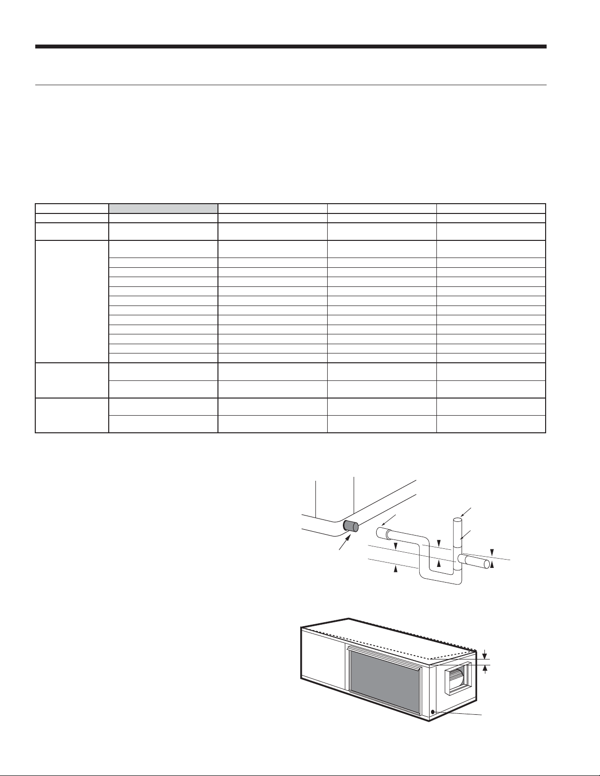
Duct System
An air outlet collar is provided on vertical top and rear air
discharge units and all horizontal units to facilitate a duct
connection (vertical bottomflow units have no collar). A
flexible connector is recommended for discharge and return
air duct connections on metal duct systems. Uninsulated
duct should be insulated with a minimum of 25.4mm duct
insulation. Application of the unit to uninsulated ductwork
in an unconditioned space is not recommended as the unit’s
performance will be adversely affected.
If the unit is connected to existing ductwork, check the duct
system to ensure that it has the capacity to accommodate
the air required for the unit application. If the duct is too
small, as in the replacement of heating only systems, larger
ductwork should be installed. All existing ductwork should
be checked for leaks and repaired if necessary.
The duct system should be sized according to the table
below to handle the design airflow quietly and efficiently.
To maximize sound attenuation of the unit blower, the
supply and return plenums should include an internal duct
liner of fiberglass or constructed of ductboard for the first
few meters. On systems employing a sheet metal duct
system, canvas connectors should be used between the
unit and the ductwork. If air noise or excessive airflow is a
problem, the blower speed can be changed.
Model Design Airflow L/s
NVK009
NVK012
NVK015
708
849.6
1038.4
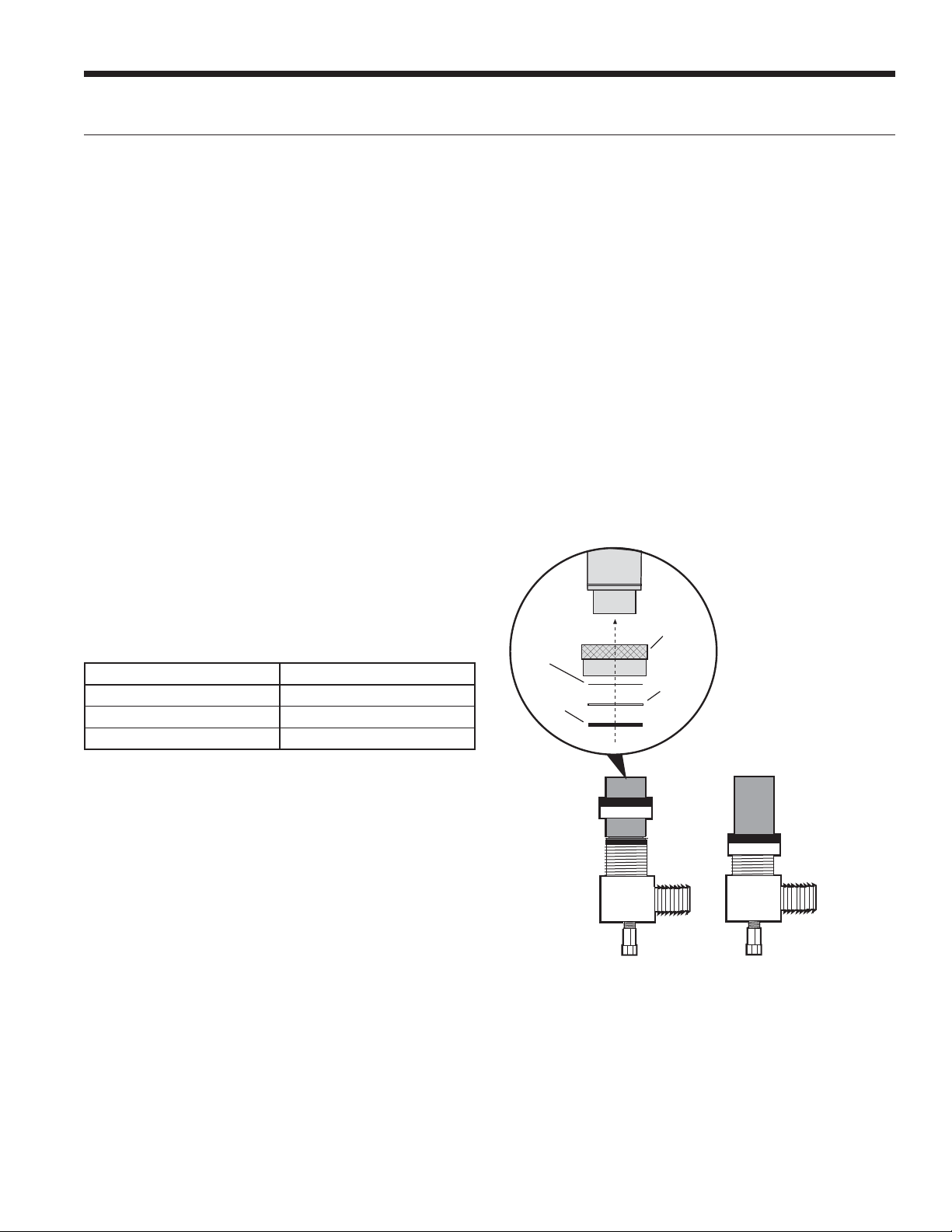
seal is in the swivel connector prior to attempting any
connection. The rubber seals are shipped attached to the
waterline. To make the connection to a ground loop system,
mate the brass connector (supplied in CK4LI connector
kit) against the rubber gasket in the swivel connector and
thread the female locking ring onto the pipe threads, while
maintaining the brass connector in the desired direction.
Tighten the connectors by hand, then gently snug the
fitting with pliers to provide a leak-proof joint. When
connecting to an open loop (ground water) system, thread
any 25.4mm MPT fitting (SCH80 PVC or copper) into the
swivel connector and tighten in the same manner as noted
above. The open and closed loop piping system should
include pressure/temperature taps for serviceability.
Never use flexible hoses smaller than 25.4mm inside
diameter on the unit. Limit hose length to 3.1 meters per
connection. Check carefully for water leaks.
Figure 4: Swivel Connections
Stainless
Steel
Snap Ring
Gasket
Material
Locking
Ring
Gasket
Support
Sleeve
Water Piping
The proper water flow must be provided to each unit
whenever the unit operates. To assure proper flow, use
pressure/temperature ports to determine the flow rate.
These ports should be located at the supply and return
water connections on the unit. The proper flow rate cannot
be accurately set without measuring the water pressure
drop through the refrigerant-to-water heat exchanger.
All source water connections on residential units are swivel
piping fittings (see Figure 4) that accept a 25.4mm male
pipe thread (MPT). The swivel connector has a rubber
gasket seal similar to a rubber hose gasket, which when
mated to the flush end of any 25.4mm threaded pipe
provides a leak-free seal without the need for thread
sealing tape or compound. Check to ensure that the rubber
7
Page 8
7 SERIES 50Hz 700A11 INSTALLATION MANUAL
General Installation Information cont.
Water Quality
In ground water situations where scaling could be heavy
or where biological growth such as iron bacteria will be
present, a closed loop system is recommended. The heat
exchanger coils in ground water systems may, over a period
of time, lose heat exchange capabilities due to a buildup
of mineral deposits inside. These can be cleaned, but only
by a qualified service mechanic, as special solutions and
pumping equipment are required. Hot water generator coils
Material Copper 90/10 Cupronickel 316 Stainless Steel
pH Acidity/Alkalinity
Scaling
Corrosion
Iron Fouling
(Biological Growth)
Erosion
NOTES: Grains = ppm divided by 17
mg/L is equivalent to ppm
Calcium and
Magnesium Carbonate
Hydrogen Sulfide
Chlorine Less than 0.5 ppm Less than 0.5 ppm Less than 0.5 ppm
Chlorides Less than 20 ppm Less than 125 ppm Less than 300 ppm
Carbon Dioxide Less than 50 ppm 10 - 50 ppm 10 - 50 ppm
Ammonia Less than 2 ppm Less than 2 ppm Less than 20 ppm
Ammonia Chloride Less than 0.5 ppm Less than 0.5 ppm Less than 0.5 ppm
Ammonia Nitrate Less than 0.5 ppm Less than 0.5 ppm Less than 0.5 ppm
Ammonia Hydroxide Less than 0.5 ppm Less than 0.5 ppm Less than 0.5 ppm
Ammonia Sulfate Less than 0.5 ppm Less than 0.5 ppm Less than 0.5 ppm
Total Dissolved Solids (TDS) Less than 1000 ppm 1000 - 1500 ppm 1000 - 1500 ppm
LSI Index +0.5 to -0.5 +0.5 to -0.5 +0.5 to -0.5
Iron, FE
Bacterial Iron Potential
Iron Oxide
Suspended Solids
Threshold Velocity
(Fresh Water)
Less than 0.5 ppm (rotten egg
Sulfates Less than 125 ppm Less than 125 ppm Less than 200 ppm
2
+ (Ferrous)
smell appears at 0.5 ppm)
Less than 1 ppm, above this
level deposition will occur
Less than 10 ppm and filtered
for max. of 600 micron size
7 - 9 7 - 9 7 - 9
(Total Hardness)
less than 350 ppm
< 0.2 ppm < 0.2 ppm < 0.2 ppm
< 1.8 m/sec < 1.8 m/sec < 1.8 m/sec
can likewise become scaled and possibly plugged. In areas
with extremely hard water, the owner should be informed
that the heat exchanger may require occasional flushing.
Units with cupronickel heat exchangers are recommended
for open loop applications due to the increased resistance
to build-up and corrosion, along with reduced wear caused
by acid cleaning. Failure to adhere to the guidelines in the
water quality table could result in the loss of warranty.
(Total Hardness)
less than 350 ppm
10 - 50 ppm Less than 1 ppm
Less than 1 ppm, above this
level deposition will occur
Less than 10 ppm and filtered
for max. of 600 micron size
(Total Hardness)
less than 350 ppm
Less than 1 ppm, above this
level deposition will occur
Less than 10 ppm and filtered
for max. of 600 micron size
2/22/12
Low Water Coil Limit
Set the freeze sensing switch SW2-1 on the Aurora Base
Control (ABC) printed circuit board for applications using
a closed loop antifreeze solution to “LOOP” (-9.4°C). On
applications using an open loop/ground water system (or
closed loop no antifreeze), set this dip switch to “WELL”
(-1.1°C), the factory default setting. (Refer to the DIP Switch
Settings table in the Aurora Control section.)
Condensate Drain
On vertical units, the internal condensate drain assembly
consists of a drain tube which is connected to the drain
pan, a 19.1mm PVC female adapter and a flexible connecting
hose. The female adapter may exit either the front or the
side of the cabinet. The adapter should be glued to the
field-installed PVC condensate piping. On vertical units, a
condensate hose is inside all cabinets as a trapping loop;
therefore, an external trap is not necessary.
On horizontal units, a PVC stub is provided for condensate
drain piping connection. An external trap is required (see
below). If a vent is necessary, an open stand pipe may be
applied to a tee in the field-installed condensate piping.
Figure 5: Horizontal Drain Connection
PVC coupling
PVC tube stub
38.1 mm
Figure 6: Unit Pitch for Drain
8
Vent (if needed)
PVC tube stub
10.4 mm per meter
38.1 mm
12.7 mm Pitch
Drain
Page 9
Closed Loop Ground Source Systems
7 SERIES 50Hz 700A11 INSTALLATION MANUAL
NOTE: For closed loop systems with antifreeze protection,
set SW2-1 to the “LOOP” (-9.4°C) position. (Refer to the
DIP Switch Settings table in the Aurora Control section.)
Once piping is completed between the unit, pumps and the
ground loop (see figure below), final purging and charging
of the loop is required. A flush cart (or a 1.5 HP pump
minimum) is needed to achieve adequate flow velocity
in the loop to purge air and dirt particles from the loop
itself. Antifreeze solution is used in most areas to prevent
freezing. Flush the system adequately to remove as much
air as possible then pressurize the loop to a static pressure
of 276-345 kPa (summer) or 345-517 kPa (winter). This is
normally adequate for good system operation. Loop static
pressure will fluctuate with the seasons. Pressures will be
higher in the winter months than during the cooling season.
This fluctuation is normal and should be considered when
initially charging the system.
After pressurization, be sure to turn the venting (burping)
screw in the center of the pump two (2) turns open (water
will drip out), wait until all air is purged from the pump,
then tighten the plug. Variable speed pumps do not have
a venting screw. Ensure that the loop pumps provide
adequate flow through the unit(s) by checking the pressure
drop across the heat exchanger and comparing it to the unit
capacity data in this catalog. 0.14-0.19 L/s of flow per ton of
cooling capacity is recommended in earth loop applications.
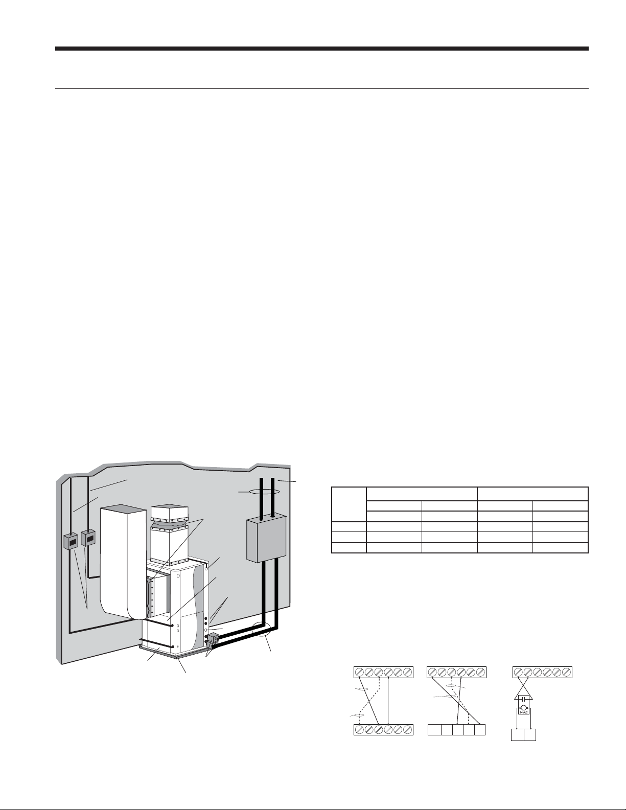
Figure 7: Closed Loop Ground Source Application
Multiple Units on One Flow Center
NOTE: This feature is only available in the Aurora Advanced
Control package (AXB board), NOT the Aurora Base
Control (ABC).
When two units are connected to one loop pumping system,
pump control is automatically achieved by connecting the
SL terminals on connector P2 in both units with 2-wire
thermostat wire. These terminals are polarity dependant (see
Figure 8). The loop pump(s) may be powered from either
unit, whichever is more convenient. If either unit calls, the loop
pump(s) will automatically start. The use of two units on one
flow center is generally limited to a total of 1.26 L/s capacity.
Variable Speed Pump Setup
When using a variable speed pump flow center (FCV1-GL,
FCV2-GL, FCV1-GLNP, or FCV2-GLNP) the use of an AID
Tool will be necessary to adjust minimum and maximum
flow rates. The factory default is: minimum=50% and
maximum=100% speed levels. See the 7 Series Variable
Speed Pump Setup and Modulating Water Valve Setup
instructions within the Unit Startup section which is located
in the back of this manual. Always ensure that there is
adequate flow for the heat pump. See Recommended
Minimum/Maximum Flow Rates table.
NOTE: When sharing a flow center, the variable speed heat
pump should be the primary unit. When two variable speed
heat pumps share a flow center, the larger capacity heat
pump should be the primary unit.
Disconnects
(If Applicable)
Unit Supply
Auxiliary Heat
Supply
Low
Voltage to
Thermostat
P/T Plugs
Vibration Absorbing Pad
®
GeoLink
Polyethylene w/
®
Armaflex
Insulation
Flexible Duct
Collar
Auxiliary
Heater
Knockout
Unit Power
Hot Water Generator
Connections
Drain
P/T
GeoLink
Flow
Center
Insulated piping
or hose kit
NOTE: Additional information can be found in Flow
Center installation manual and Flush Cart manual.
TO
LOOP
®
Recommended Minimum/Maximum Flow Rates
Model
and Size
NVK009
NVK012
NVK015
Closed Loop Open Loop
Min. Flow Rate Max. Flow Rate Min. Flow Rate Max. Flow Rate
L/s L/s L/s L/s
0.3 0.8 0.3 0.5
0.3 0.9 0.3 0.6
0.3 1.1 0.3 0.8
5/23/13
Figure 8: Primary/Secondary Hook-up
7 Series to
5 or 7 Series Units
7 Series Unit #1
with AXB Board
With pump
wired to Unit 1
With pump
wired to
Unit 2
OUTIN C C
OUTIN C C
VSPUMPSLAVE
12
12
VSPUMPSLAVE
7 Series to
Envision Units
7 Series Unit #1
with AXB Board
With pump
wired to
Unit 1
Shut
Down
OUTIN C C
CC
VSPUMPSLAVE
12
With pump
wired to
Unit 2
SL1InSL1
Out
7 Series to
Electromechanical Units
7 Series Unit #1
with AXB Board
VSPUMPSLAVE
12
OUTIN C C
C
S
9
Page 10
7 SERIES 50Hz 700A11 INSTALLATION MANUAL
Open Loop Ground Water Systems
Typical open loop piping is shown below. Always maintain
water pressure in the heat exchanger by placing water
control valves at the outlet of the unit to prevent mineral
precipitation. Use a closed, bladder-type expansion tank
to minimize mineral formation due to air exposure. Ensure
proper water flow through the unit by checking pressure
drop across the heat exchanger and comparing it to the
figures in unit capacity data tables in the specification
catalog. 0.095-0.13 L/s of flow per ton of cooling capacity
is recommended in open loop applications.
Discharge water from the unit is not contaminated in any
manner and can be disposed of in various ways, depending
on local codes, i.e. recharge well, storm sewer, drain field,
adjacent stream or pond, etc. Most local codes forbid the use
of sanitary sewer for disposal. Consult your local building and
zoning departments to assure compliance in your area. On
VS systems, a modulating valve, as shown in figure 9a is the
best choice to limit water consumption. The WWKVS well
water kit with modulating valve is the recommended setup
for open loop applications with variable speed products.
NOTE: For open loop/groundwater systems or systems
that do not contain an antifreeze solution, set SW2-Switch
#1 to the “WELL” (-1.1°C) position. (Refer to the DIP Switch
Settings in the Aurora Control section.) Slow opening/
closing solenoid valves (type VM or V) or modulating
valves are recommended to eliminate water hammer.
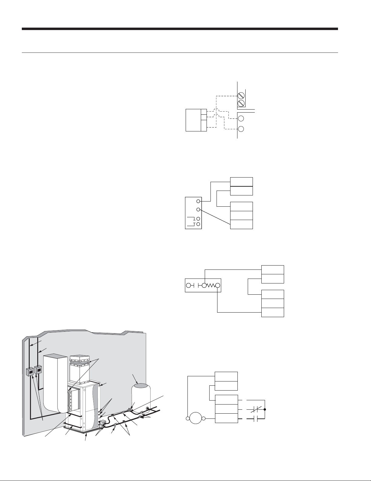
Figure 9a: Modulating Water Valve Connection Option
Typical 0-10VDC modulating water valve.
AXB BOARD
2 1
GND
24 VAC
0-10DC
1
2
3
VS PUMP
C
R
VALVE
ABC BOARD
Figure 9b: Open Loop Solenoid Valve Connection Option
Typical slow operating external 24V water solenoid valve
(type V) wiring.
C
R
C
W/Y
Acc Com
ACC NC
Acc NO
V Valve ABC Board
Modulating Water Valve Setup
When using a modulating water valve (23P529-01) the use
of an AID Tool will be necessary to adjust minimum and
maximum flow rates. The factory default is: minimum=50%
and maximum=100% flow levels. See the 7 Series Variable
Speed Pump Setup and Modulating Water Valve Setup
instructions within the Unit Startup section which is located
in the back of this manual. See Recommended Minimum
and Maximum Flow Rates table. Always ensure that there is
adequate flow for the heat pump. A modulating water valve
is preferred on variable speed system to conserve water.
Figure 10: Open System - Groundwater Application
Unit Supply
Aux. Heat Supply
Flexible
Duct Collar
Rubber Bladder
Expansion Tank
Auxiliary
Disconnects
(IfApplicable)
Compressor
Line Voltage
Low Voltage
to Thermostat
and Valve
P/T Plugs
Vibration
Absorbing Pad
Heater
Knockout
Hot Water Generator
Connections
Drain
Strainer
Boiler Drains
For HX Flushing
Solenoid
Valve
valve while acid flushing)
Flow Control
(on outlet of
Solenoid Valve)
Water Out
Shut Off Valves
Shut Off Valves
(to isolate solenoid
Valve
Water In
Figure 9c: Open Loop Solenoid Valve Connection Option
Typical slow operating external 24V water solenoid valve
(type VM) wiring.
C
R
VM Valve
Acc Com
ACC NC
Acc NO
ABC Board
NOTE: SW2-4 should be “ON” and SW2-5 should be “OFF” when using
a slow opening (VM or V) water valve.
Figure 9d: Open Loop Solenoid Valve Connection Option
Typical quick operating external 24V water solenoid valve
(type PPV100 or BPV100) wiring.
C
P1
R
SV
Solenoid
Acc Com
Acc NC
Acc NO
ABC Board
1
2
P2
3
Valve
NOTE: SW2-4 and SW2-5 should be “OFF” to cycle with the compressor.
10
Page 11
Hot Water Generator Connections
7 SERIES 50Hz 700A11 INSTALLATION MANUAL
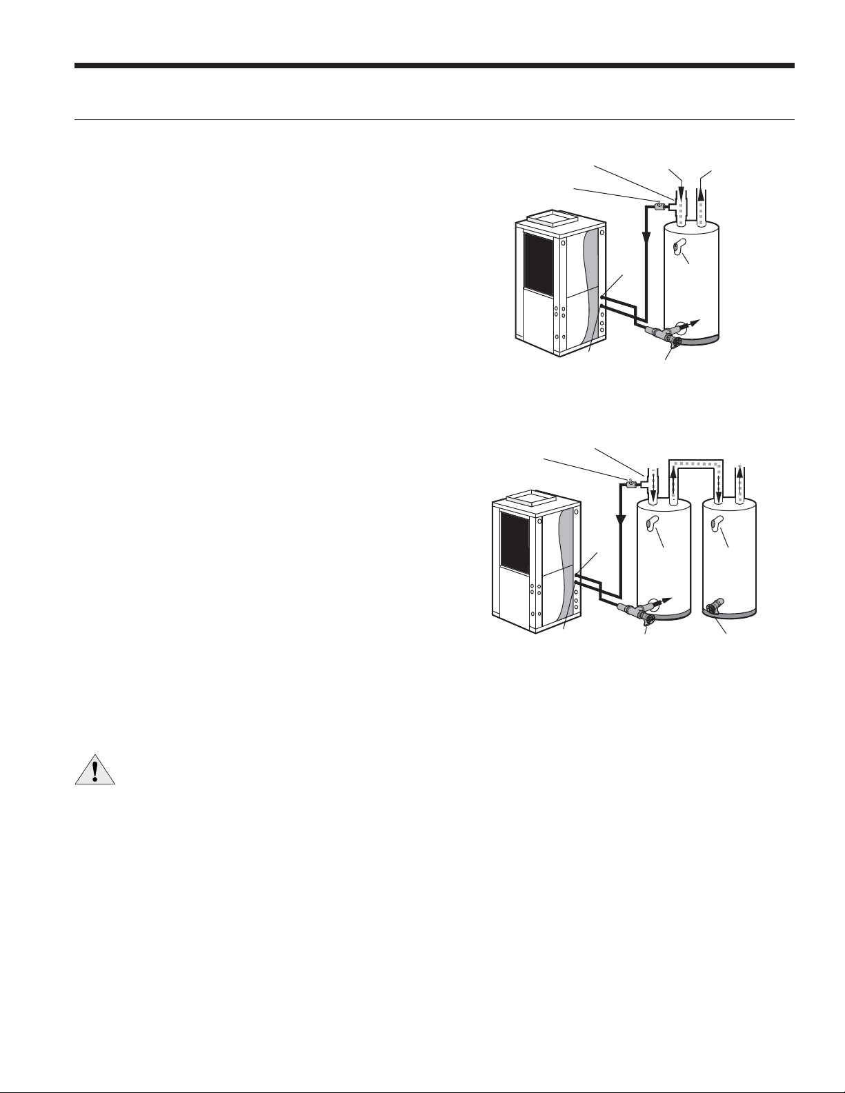
To maximize the benefits of the hot water generator a
minimum 189-liter water heater is recommended for higher
demand applications, use an 302.8-liter water heater or
two 189-liter water heaters connected in a series as shown
below. Two tanks plumbed in a series is recommended to
maximize the hot water generator capability. Electric water
heaters are recommended. Make sure all local electrical
and plumbing codes are met for installing a hot water
generator. Residential units with hot water generators
contain an internal circulator and fittings. A water softener
is recommended with hard water (greater than 10 grains or
170 total hardness).
NOTES: 1) Using a preheat tank, as shown in Figure 12, will
maximize hot water generator capabilities. 2) The hot water
generator coil is constructed of vented double wall copper
suitable for potable water.
Water Tank Preparation
To install a unit with a hot water generator, follow these
installation guidelines.
1. Turn off the power to the water heater.
2. Attach a water hose to the water tank drain
connection and run the other end of the hose to an open
drain or outdoors.
3. Close the cold water inlet valve to the water heater tank.
4. Drain the tank by opening the valve on the bottom
of the tank, then open the pressure relief valve or hot
water faucet.
5. Flush the tank by opening the cold water inlet valve to
the water heater to free the tank of sediments. Close
when draining water is clear.
6. Disconnect the garden hose and remove the drain valve
from the water heater.
7. Refer to Plumbing Installation and Hot Water
Generator Startup.
Figure 11: Typical Hot Water Generator Installation
19.1mm x 19.1mm x 12.7mm tee
Venting Waste
Valve or Vent
Coupling
HWG
Water Out
HWG
Water In
Cold
Water In
P/T Relief
Drain Valve
Valve
Hot
Water Out
In
Figure 12: Hot Water Generator Installation In Preheat Tank
19.1mm x 19.1mm x
tee
Venting Waste Valve
or Vent Coupling
Water In
12.7mm
HWG
HWG
Water Out
Cold
Water In
P/T Relief
Valve
Storage
Tank
Water Out
P/T Relief
In
Drain ValveDrain Valve
Electric Powered
Water Heater
Hot
Valve
NOTE: This configuration maximizes hot water
generator capability.
CAUTION: Elements will burn out if energized dry.
11
Page 12
7 SERIES 50Hz 700A11 INSTALLATION MANUAL
Hot Water Generator Connections cont.
Plumbing Installation
1. Inspect the dip tube in the water heater cold inlet
for a check valve. If a check valve is present it must
be removed or damage to the hot water generator
circulator will occur.
2. Remove drain valve and fitting.
3. Thread the 19.1mm NPT x 88.9mm brass nipple into the
water heater drain port.
4. Attach the center port of the 19.1mm FPT tee to the
opposite end of the brass nipple.
5. Attach the 12.7mm copper to 19.1mm NPT adaptor to the
side of the tee closest to the unit.
6. Install the drain valve on the tee opposite the adaptor.
7. Run interconnecting tubing from the tee to hot water
generator water out.
8. Cut the cold water “IN” line going to the water heater.
9. Insert the reducing solder tee in line with cold water “IN”
line as shown.
10.
Run interconnecting copper tubing between the unit hot
water generator water “IN” and the tee (
The recommended maximum distance is 15.24 meters.
11.
To prevent air entrapment in the system, install a vent
coupling at the highest point of the interconnecting lines.
12. Insulate all exposed surfaces of both connecting water
lines with 9.5mm wall closed cell insulation.
NOTE: All plumbing and piping connections must comply
with local plumbing codes.
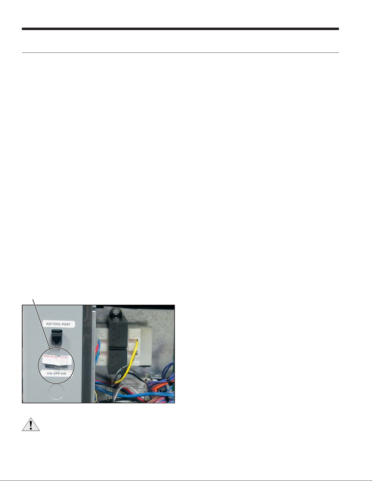
Hot Water Generator Switch
The hot water generator switch is taped in the disabled
position at the factory.
12.7mm
nominal).
Hot Water Generator Startup
1. Turn the hot water generator switch to the “ON”
position. The hot water generator switch will allow the
hot water generator pump to be enabled or disabled by
the service technician or homeowner.
2. Close the drain valve to the water heater.
3. Open the cold water supply to the tank.
4. Open a hot water faucet in the building to bleed air from
the system. Close when full.
5. Open the pressure relief valve to bleed any remaining air
from the tank, then close.
6. If so equipped, turn the venting (burping) screw in the
center of the pump two (2) turns open (water will drip
out), wait until all air is purged from the pump, then
tighten the plug. Use vent couplings to bleed air from
the lines.
7. Carefully inspect all plumbing for water leaks and
correct as required.
8. Before restoring electrical supply to the water heater,
adjust the temperature setting on the tank.
• On tanks with both upper and lower elements,
the lower element should be turned down to
the lowest setting, approximately 37.8°C. The
upper element should be adjusted to 48.9°C to
54.4°C. Depending upon the specific needs of
the customer, you may want to adjust the upper
element differently.
• On tanks with a single element, lower the
thermostat setting to 48.9°C.
9. After the thermostat(s) is adjusted, replace the access
cover and restore electrical supply to the water heater.
10. Make sure that any valves in the hot water generator
water circulating circuit are open.
11. Use an AID Tool to enable HWG and select the desired
water heating set point. Selectable set points are 37.8°C
– 60°C in 5°C increments (default 54.4°C). From the
Main Menu of the AID Tool select Setup, then AXB Setup.
12. Turn on the unit to first stage heating..
13. The hot water generator pump should be running. When
the pump is first started, turn the venting (burping)
screw (if equipped) in the center of the pump two (2)
turns open until water dribbles out, then replace. Allow
the pump to run for at least five minutes to ensure that
water has filled the circulator properly. Be sure the
switch for the hot water generator pump is “ON”.
14. Allow the unit to heat water for 15 to 20 minutes to be
sure operation is normal.
CAUTION: Never operate the HWG circulating
pump while dry. If the unit is placed in operation
before the hot water generator piping is
connected, be sure that the pump switch is set
to the OFF position.
12
Page 13
Electrical Connections
7 SERIES 50Hz 700A11 INSTALLATION MANUAL
General
Be sure the available power is the same voltage and phase
as that shown on the unit serial plate. Line and low voltage
wiring must be done in accordance with local codes or
the National Electric Code, whichever is applicable. The
compressor has no internal overload. The circuit breaker in
the control box is the overload protection for the drive and
the compressor. Bypassing the circuit breaker could result
in damage to the compressor and voiding the warranty.
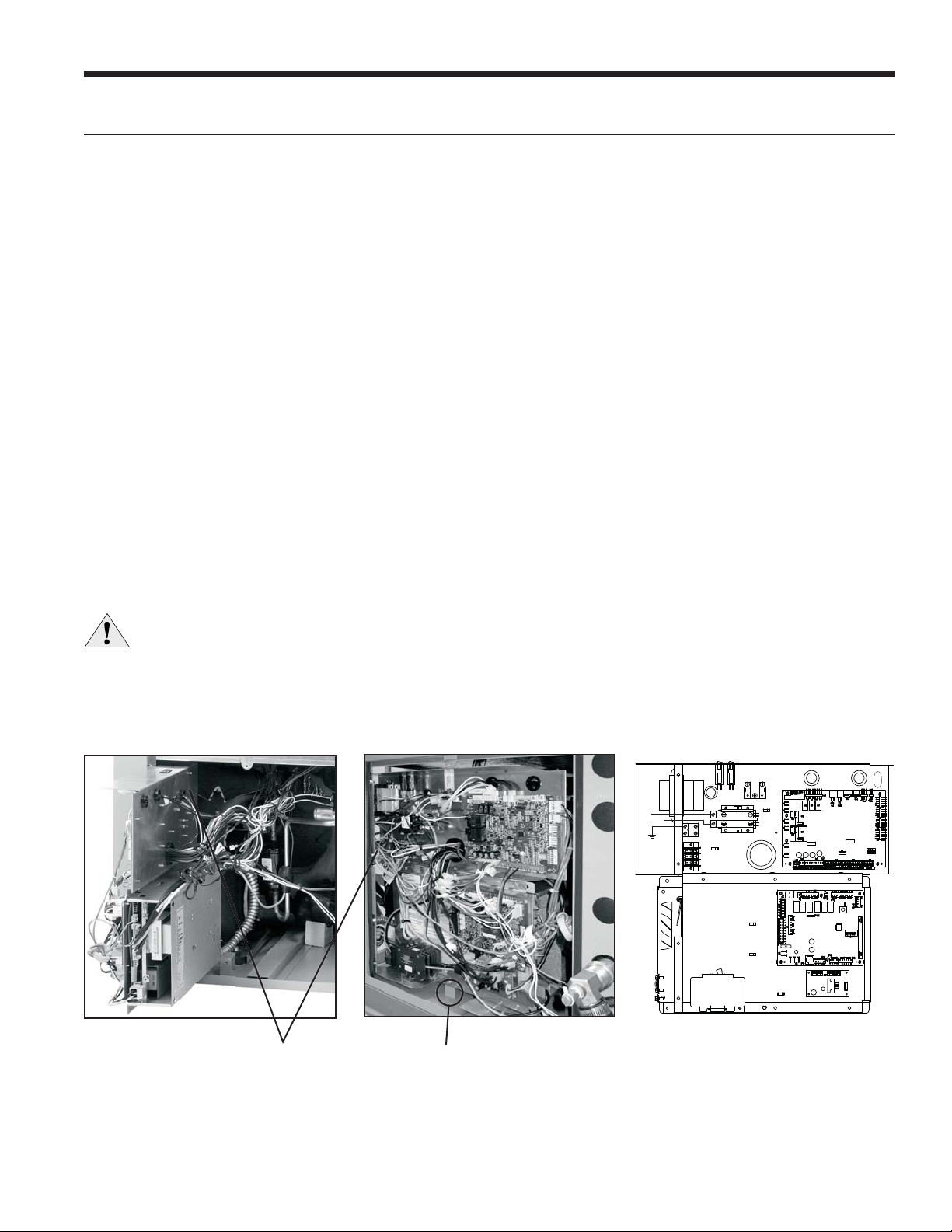
Unit Power Connection
Connect the incoming line voltage wires to L1 and L2 of
the contactor as shown in Figure 13c for single-phase unit.
Consult the Unit Electrical Data in this manual for correct
fuse sizes.
Open lower front access panel. Remove ground fastener
from bottom of control box (Figure 13b). Swing open
control box (Figure 13a). Insert power wires through
knockouts on lower left side of cabinet. Route wires
through left side of control box and connect to contactor
and ground (Figure 13c). Close control box and replace
grounding fastener before unit startup.
CAUTION: Frequent cycling of power to the drive
can damage the drive! Wait at least 5 minutes
between cycles (connecting and disconnecting
power to the drive).
Accessory Relay
A set of “dry” contacts has been provided to control
accessory devices, such as water solenoid valves on open
loop installations, electronic air cleaners, humidifiers, etc.
This relay contact should be used only with 24 volt signals
and not line voltage power. The relay has both normally
open and normally closed contacts and can operate with
either the blower or the compressor. Use DIP switch SW2-4
and 5 to cycle the relay with blower, compressor, or control
a slow opening water valve. The relay contacts are available
on terminals #2 and #3 of P2.
A second configurable accessory relay is provided on the
AXB board. When powering high VA draw components
such as electronic air cleaners or VM type open loop water
valves, R should be taken ‘pre-fuse’ from the ‘R’ quick
connect on the ABC board and not the ‘post-fuse’ ‘R’
terminal on the thermostat connection. If not, blown ABC
fuses might result.
220 Volt Operation
All 220-240 units are factory wired for 240 volt operation.
For 220 volt operation, the red and blue transformer wires
must be switched on terminal strip PS.
Figure 13a:
Wire access (control box open)
Wire Insert
Location
Figure 13b:
Wire access (control box closed)
Ground Fastener
must be installed for
proper unit ground
Figure 13c:
Line Voltage 220-240/50/1 control box
CB
PB1
L2
L1
Compressor
Drive
Overload
L1
L2
13
Page 14
7 SERIES 50Hz 700A11 INSTALLATION MANUAL
Electrical Connections cont.
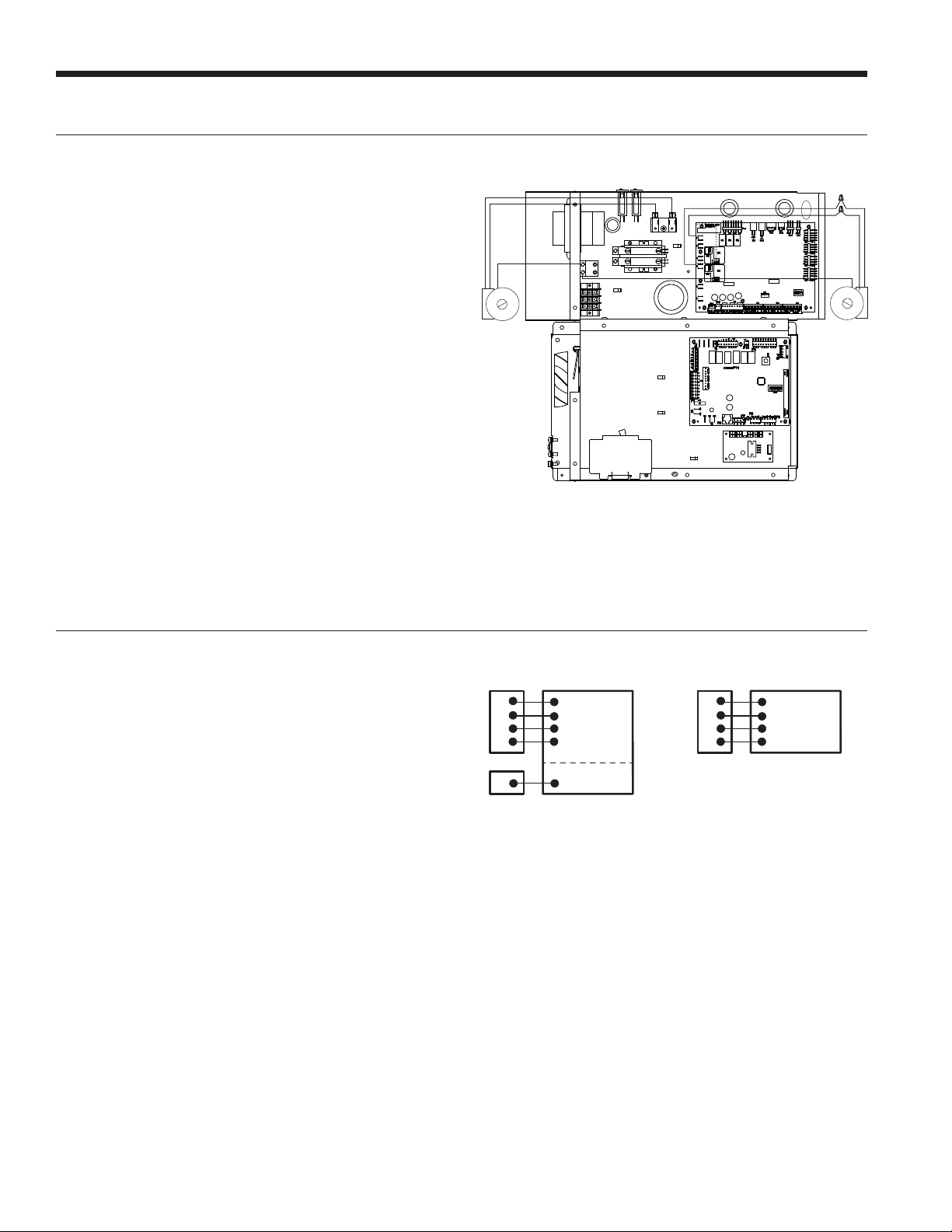
Pump Power Wiring
See Figure 14 for electrical connections from control box
to pumps.
FC1/FC2 style flow centers with fixed speed pumps
connect to PB1 in the control box. If using a variable speed
pump it should be connected to L1 and L2 on the AXB.
Figure 14: Pump Wiring 220-240/50/1
CB
PB1
L1
L2
External Loop Pump(s)
(ex. UP26-99)
220-240/50/1
1/2 hp Max
Wire Nuts
(Optional)
External Variable
Speed Loop Pump
(ex. Magna Geo)
220-240/50/1
Electronic Thermostat Installation
Position the thermostat subbase against the wall so that
it is level and the thermostat wires protrude through
the middle of the subbase. Mark the position of the
subbase mounting holes and drill holes with a 0.1875mm
bit. Install supplied anchors and secure base to the wall.
Thermostat wire must be 4-conductor, 20-AWG (minimum)
wire. Strip the wires back 6.35mm (longer strip lengths
may cause shorts) and insert the thermostat wires into
the connector as shown. Tighten the screws to ensure
secure connections. The thermostat has the same type
connectors, requiring the same wiring. See instructions
enclosed in the thermostat for detailed installation and
operation information. The W1 terminal on TPCM32U04
communicating thermostats may be hard wired to provide
aux/emergency heat in the event communication is lost
between the thermostat and the ABC microprocessor.
Figure 15: Thermostat Wiring (Communicating Style Signals)
P7
C
ABC Controller
R
–
+
P1
W
C 24VAC (Common)
R 24VAC (Hot)
B- Communication
A+ Communication
W1 (Optional)
TPCM32U04
Monochrome Thermostats
Thermostat Connection
Controller
ABC
P7
C
R
–
+
C 24VAC (Common)
R 24VAC (Hot)
DX- Communication
DX+ Communication
TPCC32U01
Color Touchscreen
Thermostat
Connection
NOTE: If using the IntelliZone2 zoning system, then
disregard the diagrams above. The IntelliZone2 system will
connect directly to the AXB control board instead. See the
IntelliZone2 installation manual for more details.
Thermostat
14
Page 15
Auxiliary Heat Ratings
7 SERIES 50Hz 700A11 INSTALLATION MANUAL
Model
EAL(H)10
EAL(H)15
EAL(H)20
Air flow level for auxiliary heat (Aux) must be above the minimum air flow in this table
Order the “H” part number when installed on horizontal and vertical rear discharge units
kW
208V 230V 009 012 015
7.2 9.6 2 519 • • •
10.8 14.4 3 590 • • •
14.4 19.2 4 708 • •
Stages Min L/s
Auxiliary Heat Electrical Data
Model
EAL(H)10
EAL(H)15
EAL(H)20
All heaters rated single phase 60 cycle and include unit fan load
All fuses type “D” time delay (or HACR circuit breaker in USA)
Supply
Circuit
Single 34.7 40 53.3 60 60 60 60 60 60 60
Single 52.0 60 75 85 80 90 80 90 70 100
L1/L2 34.7 40 53.3 60 60 60 60 60 60 60
L3/L4 17.3 20 21.7 25 25 25 25 25 20 30
Single 69.3 80 96.7 110 100 110 100 110 100 100
L1/L2 34.7 40 53.3 60 60 60 60 60 60 60
L3/L4 34.7 40 43.3 50 45 50 45 50 40 50
Heater Amps Min Circuit Amp Max Fuse (USA) Max Fuse (CAN) Max CKT BRK
208 V 240 V 208 V 240 V 208 V 240 V 208 V 240 V 208 V 240 V
Model Compatibility
7/17/13
6/1/12
Electrical Data
Model
009
*009
012
015
*With optional 1 hp Variable Speed ECM Motor
Rated Voltage of 220-240/50/1
HACR circuit breaker in USA only
All fuses Class RK-5
Rated
Voltage
220-240/50/1 198/264 10.2 18.0 22.0 30.0 0.4 5.4 4.0 31.8 37.3 40
220-240/50/1 198/264 10.2 18.0 22.0 30.0 0.4 5.4 7.0 34.8 40.3 45
220-240/50/1 198/264 12.0 23.5 28.0 35.0 0.4 5.4 7.0 40.8 47.8 50
220-240/50/1 198/264 12.0 30.0 33.0 40.0 0.4 5.4 7.0 45.8 54.1 60
Voltage
Min/Max
Compressor Drive
LRA CMCC LRA
Internal
Breaker
HWG
Pump
FLA
Ext Loop
FLA
Blower
Motor
FLA
Total Unit
FLA
Minimum
Circuit
Amp
Max Fuse
HACR
Breaker
5/08/13
15
Page 16

7 SERIES 50Hz 700A11 INSTALLATION MANUAL
Blower Performance Data
Variable Speed ECM Blower Motor
Model
009
009 w/746W*
012
015
**VS Compressor Speed
Max ESP
(Pa)
124.50
186.75
186.75
186.75
Speed 1 Speed 2 Speed 3 Speed 4 Speed 5 Speed 6 Speed 7 Speed 8 Speed 9 Speed 10 Speed 11 Speed 12
135 179
G
227 267
248
319 385 463
L
314 L 359 411 472
G
224 293
G
189 283
G
345
L
392
L
401 481 538
496 580 661
1-2 3-4 5-6 7-8 9-10 11-12
** VS Compressor speed is given for the factory default L/s settings. When the L/s default settings are changed it will change the
relationship to the compressor speed that is shown in the table. In cooling mode compressor speeds 10-12 are only available when
SuperBoost mode is selected at the thermostat.
* Optional 746W Variable Speed ECM
Factory settings are at recommended L , H and Aux positions
“G” may be located anywhere within the airflow table
“L” setting should be located within the boldface L/s range
“H” setting MUST be located within the shaded L/s range
“Aux” setting MUST be equal to or greater than “H” setting
“Aux” setting MUST be equal to or greater than the minimum allowable L/s for the auxiliary heater kit (see auxiliary heat ratings table)
Cfm is controlled within 5% up to the maximum ESP
Max ESP includes allowance for wet coil and standard filter
Air Flow
519 576 628 680
H
519 566 614 665
H
599 661 717 779
H
736 802 883 949
H
727
Aux
717
Aux
845
Aux
1010
Aux
743
769
908
1069
5/13/13
Setting Blower Speed - Variable speed ECM
The ABC board’s Yellow Config LED will flash the current
ECM blower speed selections for G, low, and high
continuously with a short pause in between. The speeds
can also be confirmed with the AID Tool under the Setup/
ECM Setup screen. The Aux will not be flashed but can be
viewed in the AID Tool. The ECM blower motor speeds can
be field adjusted with or without using an AID Tool.
Variable speed ECM Setup without an AID Tool
The blower speeds for G only, Low (Y1), and High (Y2/
Aux) can be adjusted directly at the Aurora ABC board
which utilizes the push button (SW1) on the ABC board.
This procedure is outlined in the ECM Configuration Mode
portion of the Aurora ‘Base’ Control System section. The
Aux cannot be set manually without an AID Tool.
Variable speed ECM Setup with an AID Tool
A much easier method utilizes the AID Tool to change
the airflow using the procedure below. First navigate to
the Setup screen and then select ECM Setup. This screen
displays the current ECM settings. It allows the technician to
enter the setup screens to change the ECM settings. Change
ECM Speed Info
Blower Only Speed 3
Lo Compressor 6
Hi Compressor 9
Aux Heat 10
Want To Change?
Yes
Option ◀▶NoEnter ◙
the highlighted item using the ◄
and ► buttons and then press the
◙ button to select the item.
Selecting YES will enter ECM
speed setup, while selecting NO
will return to the previous screen.
ECM Speed Setup - These screens allow the technician to
select the G, low, high, and auxiliary heat blower speed for
the ECM blower motor. Change the highlighted item using
the ▲ and ▼ buttons. Press the ◙ button to select the speed.
ECM Speed Info
1
▶ 2 ◀ G
3
4
5
6
7
8
9
10
11
12
Option
◀▶ Enter ◙
ECM Speed Info
1
2 G
▶ 3 ◀ Lo
4
5
6
7
8
9
10
11
12
Option
◀▶ Enter ◙
ECM Speed Info
1
2 G
3 Lo
4
5
▶ 6 ◀ Hi
7
8
9
10
11
12
Option
◀▶ Enter ◙
ECM Speed Info
1
2 G
3 Lo
4
5
6 Hi
7
8
9
▶10 ◀ Aux
11
12
Option
◀▶ Enter ◙
After the auxiliary heat speed setting is selected the AID
Tool will automatically transfer back to the ECM Setup screen.
Cooling Airflow Setup - These screens allow the technician
to select -15%, -10%, -5%, None or +5% change from the
heating airflow. Change the adjustment percentage using
the ▲ and ▼ buttons. Press the ◙ button to save the change.
Cooling Airflow Setup
--- ECM Only ---
The airflow will be
adjusted by the chosen
amount in cooling mode.
Adjustment:
-15%
Want To Change?
Yes
Option ◀▶NoEnter ◙
Cooling Airflow Setup
--- ECM Only ---
The airflow will be
adjusted by the chosen
amount in cooling mode.
Adjustment:
-15%
Enter ◙
▼▲
Change
16
Page 17

LEFT RETURN RIGHT RETURN
FRONT
TOP
2 ft [61 cm ]
Primary Service Access
TOP
A
DEHFIKJ G
1.9in
[4.8cm]
1.9in
[4.8cm]
M
R
Q
N
O
L
R
N
O
L
P
Q
RIGHT SIDE
B
C
B
LEFT SIDE
STS
T
C
Vertical Dimensional Data
Top Air Discharge
7 SERIES 50Hz 700A11 INSTALLATION MANUAL
Vertical
Top Flow
Model
009
cm. 65.0 80.3 138.2 5.8 18.5 40.4 48.0 26.9
012
cm. 65.0 80.3 138.2 5.8 18.5 40.4 48.0 26.9 36.3 24.9 31.2 17.5 2.8 45.7 45.7 9.7 4.3 71.4 76.2 4.3
015
cm. 65.0 80.3 148.3 5.8 18.5 40.4 48.0 26.9 36.3 24.9 31.2 17.5 2.8 45.7 45.7 9.7 4.3 71.4 86.4 4.3
Condensate is 19.05mm PVC female glue socket and is switchable from side to front
Unit shipped with deluxe 5.08cm. (field adjustable to 2.54cm) duct collar/filter rack extending from unit 8.255cm and is suitable for duct connection.
Discharge flange is field installed and extends 2.54cm from cabinet
Decorative molding and/or water connections extend 30.5mm beyond front of cabinet.
Louvered vents in the compressor section right side access panel extend 12.7 mm from side of cabinet. Allow clearance for venting.
Overall Cabinet Water Connections
A
WidthBDepthCHeight
D
Loop
In
E
Loop
Out
F
HWG
In
G
HWG
Out
H
Condensate
Loop
Water
FPT
25.4mm
Swivel
Electrical
Connections
I
J
cond
Ext
K
19.05mm
cond
Power
Supply
12.7mm
12.7mm
HWG
cond
Sweat
(I.D.)
Low
Voltage
Pump
36.3 24.9 31.2 17.5 2.8 45.7 45.7 9.7 4.3 71.4 76.2 4.3
12.7mm
Female
Discharge Connection
duct flange installed (± 2.54mm)
LMNSupply
Width
O
Supply
Depth
Return Connection
using std deluxe filter rack
PQRReturn
(± 2.54mm)
Return
Depth
Height
S
T
5/22/13
17
Page 18

7 SERIES 50Hz 700A11 INSTALLATION MANUAL
Vertical Dimensional Data cont.
Bottom Air Discharge
LEFT RETURN
C
S
S
T T
RIGHT RETURN
1.70
(4.3 cm)
4
3
C
I
K
J
2
1
G
F
E
D
B
LEFT SIDE
R
L
Q
2 ft [61 cm ]
Primary Service Access
Overall Cabinet
Bottomflow
009-
Condensate is 19.05mm PVC female glue socket and is switchable from side to front
Unit shipped with deluxe 5.08cm (field adjustable to 2.54cm) duct collar/filter rack extending from unit 8.255cm and is suitable for duct connection.
Decorative molding and/or water connections extend 30.5mm beyond front of cabinet.
Louvered vents in the compressor section right side access panel extend 12.7mm from side of cabinet. Allow clearance for venting.
Models
cm. 64.8 80.0 158.8 110.2 122.9 144.8 152.4 7.9
015
A
WidthBDepthCHeightDInEOut
12345
O
M
LEFT BOTTOM DISCHARGE
FLOOR FOOT PRINT
N
RIGHT BOTTOM DISCHARGE
FLOOR FOOT PRINT
Water Connections Electrical Knockouts
Loop
HWG
Water
F
HWG
In
G
HWG
Out
H
Cond-
ensate
FPT
25.4mm
Swivel
Sweat
(I.D.)
12.7mm
Female
B
O
I
12.7mm
cond
Low
Voltage
RIGHT SIDE
R
J
12.7mm
cond
Ext
Pump
LN
K
19.05mm
cond
Power
Supply
Q
P
Discharge Connection
duct flange installed (± 2.54mm)
LMNSupply
Width
1.90
(4.7 cm)
O
Supply
Depth
A
FRONT
PQRReturn
129.8 141.2 136.1 23.1 12.2 34.0 34.5 4.3 4.6 71.4 86.4 14.2
5
H
Return Connection
using std deluxe filter rack
(± 2.54mm)
S
Return
Depth
Height
5/29/13
T
18
Page 19

Vertical Dimensional Data cont.
Rear Air Discharge
7 SERIES 50Hz 700A11 INSTALLATION MANUAL
2 ft [61 cm ]
Primary Service Access
M
L
C
N
A
REAR VIEW
LEFT RETURN
1.90 in.
1.90 in. [4.8 cm]
[4.8 cm]
G
I
K
J
A
F
H
E
D
FRONT
O
Q
R
T
T
R
Q
P
M
S
C
S
C
C
N
B
SIDE VIEW
LEFT RETURN
B
SIDE VIEW
RIGHT RETURN
A
REAR VIEW
RIGHT RETURN
Vertical
Rear
Discharge
Model
009
012
015
Condensate is 19.05mm PVC female glue socket and is switchable from side to front
Unit shipped with deluxe 5.08cm (field adjustable to 2.54cm) duct collar/filter rack extending from unit 8.255cm and is suitable for duct connection.
Discharge flange is field installed and extends 25.4mm from cabinet
Decorative molding and/or water connections extend 30.5mm beyond front of cabinet.
Louvered vents in the compressor section right side access panel extend 12.7 mm from side of cabinet. Allow clearance for venting.
Overall Cabinet Water Connections
D
E
F
G
H
Loop
A
WidthBDepthCHeight
cm. 65.0 80.3 138.2 5.8 18.5 40.4 48.0 26.9
cm. 65.0 80.3 138.2 5.8 18.5 40.4 48.0 26.9 36.3 24.9 31.2 33.8 34.5 100.1 23.1 20.6 4.3 71.4 76.2 4.3
cm. 65.0 80.3 148.3 5.8 18.5 40.4 48.0 26.9 36.3 24.9 31.2 33.8 34.5 110.2 23.1 20.6 4.3 71.4 86.4 4.3
Loop
In
Loop
Out
HWG
In
HWG
Out
Cond-
ensate
Water
FPT
25.4mm
Swivel
HWG
Sweat
(I.D.)
12.7mm
Female
Electrical
Connections
I
J
cond
Ext
K
19.05mm
cond
Power
Supply
12.7mm
12.7mm
cond
Low
Voltage
Pump
36.3 24.9 31.2 33.8 34.5 100.1 23.1 20.6 4.3 71.4 76.2 4.3
Discharge Connection
duct flange installed (± 2.54mm)
L
M
Supply
Supply
Width
NOP QRReturn
Depth
Return Connection
using std deluxe filter rack
(± 2.54mm)
Depth
19
S
Return
Height
T
5/29/13
Page 20

7 SERIES 50Hz 700A11 INSTALLATION MANUAL
Horizontal Dimensional Data
1.9in
[4.8cm]
IKJ
FRONT VIEW
A
S
2 ft [61 cm ]
Primary Service Access
EFG
D
TOP VIEW
Q
SIDE DISHCARGE VIEW
B
P
2.1in
[5.4cm ]
MOUNT (2) HANGER BRACKETS
AS SHOWN TO ALLOW ACCESS
TO FILTER
END VIEW
L
L
ON
M
C
H
AS SHOWN LR UNIT (RR UNIT ON OPPOSITE SIDE—SAME DIMENSIONS)
Electrical Connections
I
Horizontal
Models
009
012
015
Condensate is 19.05mm PVC female glue socket and is switchable from side to front
Unit shipped with deluxe 5.08cm (field adjustable to 2.54cm) duct collar/filter rack extending from unit 8.255cm and is suitable for duct connection.
Discharge flange is field installed and extends 25.4mm from cabinet
Decorative molding and/or water connections extend 30.5mm beyond front of cabinet.
Louvered vents in the compressor section right side access panel extend 12.7 mm from side of cabinet. Allow clearance for venting.
Overall Cabinet Water Connections
F
G
H
A
WidthBDepthCHeightDInEOut
cm. 65.0 195.6 54.1 5.8 18.5 40.4 48.0 2.0
cm. 65.0 195.6 54.1 5.8 18.5 40.4 48.0 2.0 36.3 24.9 31.2 34.5 33.5 7.1 102.6 48.0 3.3
cm. 65.0 208.3 54.1 5.8 18.5 40.4 48.0 2.0 36.3 24.9 31.2 34.5 33.5 7.1 115.3 48.0 3.3
HWG
In
HWG
Out
Condensate
Loop
Water
FPT
25.4mm
Swivel
HWG
Sweat
(I.D.)
12.7mm
Female
12.7mm
Voltage
J
12.7mm
cond
Ext
Pump
19.05mm
cond
Power
Supply
cond
Low
36.3 24.9 31.2
Discharge Connection
K
duct flange installed
LMSupply
See
Chart
(± 2.54mm)
Supply
Height
34.5 33.5
N
Depth
Return Connection
using std deluxe filter rack
OPQReturn
See
Chart
Depth
7.1 102.6 48.0 3.3
(± 2.54mm)
O
R
Return
Height
S
R
S
5/29/13
Units Not Shown Above L O
Right Return End Discharge
Right Return Side Discharge
Left Return End Discharge
Left Return Side Discharge
cm 7.1 11.8
cm 12.4 17.5
cm 12.4 19.4
cm 7.1 17. 5
20
Page 21

Physical Data
7 SERIES 50Hz 700A11 INSTALLATION MANUAL
Model
Compressor (1 each) Variable Speed Scroll
Factory Charge R-410A, kg Vertical 2.69 3.40 3.96
Factory Charge R-410A, kg Horizontal 2.69 3.85 4.19
ECM Blower Motor & Blower
Blower Motor Type/Speeds ECM Variable Speed
Blower Motor - W ECM 373 746 746
High Static Blower Motor - W ECM 746 N/A N/A
Blower Wheel Size (Dia x W), mm ECM 279 x 254 279 x 254 279 x 254
High Static Blower Wheel Size - [Dia. x W], mm ECM 279 x 254 N/A N/A
Coax and Water Piping
Water Connections Size - Swivel - in [mm] 1 [25.4] 1 [25.4] 1 [25.4]
HWG Connection Size - Female Sweat I.D. - in [mm] 1/2 [12.7] 1/2 [12.7] 1/2 [12.7]
Coax & Piping Water Volume - l 6.1 6.1 8.7
Vertical
Air Coil Dimensions (H x W), mm 813 x 635 813 x 635 914 x 635
Air Coil Total Face Area, m
Air Coil Tube Size, mm 9.5 9.5 9.5
Air Coil Number of rows 3 3 4
Filter Standard - 51 mm Pleated MERV 11 Throwaway, mm 813 x 762 813 x 762 914 x 762
Weight - Operating, kg 160 164 175
Weight - Packaged, kg 169 173 184
Horizontal
Air Coil Dimensions (H x W), mm 508 x 1016 508 x 1016 508 x 1143
Air Coil Total Face Area, m
Air Coil Tube Size, mm 9.5 9.5 9.5
Air Coil Number of rows 3 3 4
Filter Standard - 51 mm Pleated MERV 11 Throwaway, mm
Weight - Operating, kg 176 180 188
Weight - Packaged, kg 189 193 202
2
2
009 012 015
0.570 0.570 0.641
0.570 0.570 0.641
1 - 508 x 508
1 - 508 x 559
Variable Speed
1 - 508 x 508
1 - 508 x 559
1 - 508 x 635
1 - 508 x 559
5/13/13
21
Page 22

7 SERIES 50Hz 700A11 INSTALLATION MANUAL
The Aurora™ Advanced VS Control System
Aurora Advanced VS Control
Aurora Advanced VS
Control System is a
complete residential
and commercial comfort
system that brings all
aspects of the HVAC
system into one cohesive
module network. The
Aurora Advanced VS
Control features the Aurora
Base Control (ABC) and
the Aurora Expansion
Board (AXB). The variable
speed drive communicates
to the Aurora Control
and provides variable
capacity and envelope
control. The ABC features
microprocessor control
and HP, LP, loss of charge, condensate and freeze detection,
over/under voltage faults, along with communicating
thermostat capability for complete fault detection text at
the thermostat. Aurora uses the Modbus communication
protocol to communicate between modules. Each module
contains the logic to control all features that are connected
to the module. The ABC has two Modbus channels. The
first channel is configured for connecting to devices such
as a communicating thermostat, expansion board, or other
devices. The second channel is configured for connecting
the Aurora Interface Diagnostics Tool (AID Tool).
The Aurora AXB expands on the capability of the ABC
control board. The additional features include active
dehumidification, SuperBoost cooling mode, loop pump
linking, intelligent hot water generator control, variable
speed pump capability, and also allows for optional energy,
refrigeration, and performance monitoring add-on sensor
kits. The AXB also features a second field configurable
accessory relay, and two home automation inputs that
are AID configurable for different types of alarms from
sump pumps to home security. The Smart Grid input is
AID configurable with many options to react to Utility
controlled relay operation for On Peak optimization.
The AXB also expands the communication capability for
IntelliZone2 ready operation as well as other expansion
with the ClimateTalk protocol.
Aurora Control Features Description Aurora Advanced VS
Advanced Microprocessor Features
Advanced Hot Water Generator
Advanced Speed Pump Control
Home Automation Alarm Input
IntelliZone2
Aurora Interface and Diagnostics
Control
Variable Speed Pump
Active Dehumidification
SuperBoost
Smart Grid/Utility Input
HAN/Smart Grid Com
(AWL and Portal) Kit
®
Compatibility
Service Device Description Aurora Advanced VS
(AID) Tool
Smart Grid, Home Automation Alarm Inputs, and Accessory2 Relay (HRV/ERV)
Microprocessor and separate power relay for Hot Water Generator Pump with digital
temperature monitoring and multiple HWG setpoint selection.
Microprocessor and separate power relay for loop pump and inline circuit breakers
and loop pump slaving.
Capable of setup, monitoring and controlling a variable speed flow center.
Coil temperature is monitored and air flow is reduced for maximum latent moisture
removal.
Allow the variable speed compressor to ramp up an extra 30% of cooling capacity if
needed. This extra ‘SuperBoost’ will only be available for a 24 hr period and then the
unit will revert to normal operation.
Allows simple input to externally enable of occupied/unoccupied mode for basic
utility time of use programs.
Allows simple input to signal sump, security, or smoke/CO sensor alarms from other
home automation or security systems. The two inputs can be field configured to a
number of options and logic.
Allows direct communication of the Aurora to Smart Meters, Home Automation
Network and Internet.
IntelliZone2 communicates to the heat pump via the AXB board. IntelliZone requires
traditional thermostat inputs and is not compatible with the 7 Series.
Allows setup, monitoring and troubleshooting of any Aurora Control.
NOTE: Although the ABC has basic compatibility with all Aurora, new product
features may not be available on older AID Tools. To simplify the basic compatibility
ensure the version of AID is at least the same or greater than the ABC software
version.
7 Series Variable
Speed Only
Dry Contact x1
Dry Contact x2
Optional AWL
Optional IntelliZone2
For Service
(Ver. 2.xx or greater)
•
•
•
•
•
22
Page 23

7 SERIES 50Hz 700A11 INSTALLATION MANUAL
S
The Aurora Advanced VS Control System cont.
Add On Control Feature Kits
(field or factory Installed)
Geo Energy Monitoring Kit
Refrigeration Monitoring Kit
Performance Monitoring Kit
Data Logging (AWL) Kit
HAN/Smart Grid Com
(AWL and Portal) Kit
Add On Thermostats and Zoning Description Aurora Advanced VS
TPCM32U04 - MonoChrome
Communicating Thermostat
TPCC32U01 - Color Touchscreen
Communicating Thermostat
Monitors real time power consumption of compressor, blower, aux heat and pump.
Requires thermostat TPCM32U04 or TPCC32U01.
Monitors real time pressures, temperatures, superheat, and subcooling. Standard
Monitors air and water temperatures, and water flow rate and calculates heat of
extraction/rejection.
Allows data logging of up to 12 months. Can also be temporarily installed. Optional
Allows direct communication of the Aurora to Smart Meters, HAN, and internet. Optional
Elite Stat with full English fault codes and alerts, communicating thermostat;
Required for viewing Energy Monitoring. Monochrome thermostat allows
instantaneous energy measurement only.
4.3 in. color touchscreen communicating thermostat with full English fault codes
and alerts; Required for viewing Energy Monitoring. Color thermostat allows
instantaneous and 13 month history.
Includes color main thermostat and up to 6 zones (with variable speed), 4 zones
(with dual capacity), and 2 zones (with single speed). There are 3 thermostat
options (MasterStat, SensorStat, ZoneStat).
Description Aurora Advanced VS
Standard
Optional Sensor Kit
Optional
Optional
Optional
IntelliZone2® Zoning
NOTES: The IntelliZone2 or one of the communicating thermostats shown above must be used to control the variable speed heat pump.
Aurora Advanced VS Control Features
NOTE: Refer to the Aurora Advanced VS Control Application
• Accessory output with N.O. and N.C.
• Modbus communication
and Troubleshooting Guide and the Instruction Guide: Aurora
Interface and Diagnostics (AID) Tool for additional information.
Variable Speed ECM Blower Motor
A variable speed ECM blower motor is driven directly using
Control Features
oftware ABC VS Version 2.0 Variable Capacity Compressors
• Random start at power up
• Anti-short cycle protection
• High and low pressure cutouts
• Loss of charge
• Water coil freeze detection
• Air coil freeze detection
• Over/under voltage protection
• Condensate overflow sensor
• Load shed
• Dehumidification (where applicable)
• Emergency shutdown
• Diagnostic LED
• Test mode push button switch
• Two auxiliary electric heat outputs
• Alarm output
the onboard PWM output. Multiple blower speeds are
available based upon requirements of the compressor and
electric heat. The blower speeds can be changed either
by the variable speed ECM manual configurations mode
method or by using the Aurora AID Tool directly.
Advanced Hot Water Generator Control
(Domestic Hot Water Option)
An AID Tool selectable temperature limit and
microprocessor control of the process is featured. This will
maximize hot water generation and prevent undesirable
energy use. An alert will occur when the hot water input
temperature is at or above the set point (54.4°C default)
for 30 continuous seconds. This alert will appear as an E15
on the AID Tool and the hot water pump de-energizes. Hot
water pump operations resume on the next compressor
cycle or after 15 minutes of continuous compressor
operation during the current thermostat demand cycle.
Since compressor hot gas temperature is dependent on
23
Page 24

7 SERIES 50Hz 700A11 INSTALLATION MANUAL
The Aurora Advanced VS Control System cont.
loop temperature in cooling mode, loop temperatures may
be too low to allow proper heating of water. The control will
monitor water and refrigerant temperatures to determine if
conditions are satisfactory for heating water.
VS Drive and Envelope Control
The VS drive operates the compressor between 20 and
100% capacity. The VS drive communicates any out of
refrigerant envelope conditions to the Aurora and will
attempt to adjust the compressor speed to keep within
the envelope. These conditions are measured using the
discharge and suction pressure transducers, discharge
temperature, and current sensors of the drive.
IntelliZone2 Zoning Compatibility
(Optional IntelliZone2 Zoning)
A dedicated input to connect and communicate with the
IntelliZone2 (IZ2) zoning system is provided on P7 on the
AXB control board. There is a dedicated communication port
using a proprietary ModBus protocol. The AXB is standard
on variable speed systems. An AXB can be added to other
selected ABC only systems as well. Then an advanced
communicating IntelliZone2 zoning system can be added
to ABC-only systems. Consult the IntelliZone2 literature for
more information.
Loop Pump Linking
This input and output are provided so that two units can
be linked together with a common flow center. When either
unit has a call for loop outputs, both unit’s loop pump
relays and variable speed pumps are energized. The flow
center then can simply be wired to either unit. The output
from one unit should be routed to the input of the other. If
daisy chained, up to 16 heat pumps can wired and linked
together in this fashion.
Advanced Communication Ports
Communication ports P6 and P8 will provide future
expansion via dedicated protocols. These are for future use.
Smart Grid/On Peak (SG) Input
The 'Smart Grid/On Peak' input was designed to allow
utilities to utilize simple radio controlled switches to
control the On Electric Peak behavior of the 5 and 7 Series
Geothermal Heat Pumps and provide demand reduction.
With a closed contact signal, this input will limit the
operation and thus the power consumption of the unit
by disabling the compressor and electric heat as long as
the signal is present. Code 7 will flash on the Green LED
signifying the 'On Peak' mode. On Peak will also display on
communicating thermostats.
Electronic Expansion Valve (EEV)
The electronic expansion valve is operated by the EEV
board and is set to maintain optimal superheat setting
for maximum efficiency. All operation parameters are
communicated to the VS drive and the Aurora system.
Variable Speed Pump
This input and output are provided to drive and monitor
a variable speed pump. The VS pump output is a PWM
signal to drive the variable speed pump. The minimum and
maximum level are set using the AID Tool. 50% and 100%
are the default settings respectively. The VS data input
allows a separate PWM signal to return from the pump
giving fault and performance information. Fault received
from the variable speed pump will be displayed as E16.
Modulating Water Valve
This output is provided to drive a modulating water valve.
Through advanced design the 0-10VDC valve can be
driven directly from the VS Pump output. The minimum
and maximum level are set in the same way as the VS
pump using the AID Tool. 50% and 100% are the default
settings respectively.
Home Automation 1 and 2 Inputs
The Home Automation inputs are simple closed contact
inputs that will trigger an AID Tool and thermostat alert
for the homeowner. These would require optional sensors
and or equipment for connection to the AXB board. With
two inputs, two different sensors can be selected. The
selected text will then be displayed on the AID Tool and
communicating thermostats. These events will NOT alter
functionality or operation of the heat pump/accessories
and is for homeowner/service notification only.
Home Automation 1 - E23 HA1
With a closed dry contact signal, this input will cause an
alarm and Alert Code 23 to indicate on the stat or flash
on ABC. The AID Tool will allow configuration of this input
between the following selections:
• No Action
• Home Automation Fault [no lockout info only] -
Output from home automation system
• Security Alarm [no lockout info only] - Output from
home security
• Sump Alarm Fault [no lockout info only] - Switch
output from sump sensor
• Smoke/CO Alarm Fault [no lockout info only] Switch output from Smoke/CO sensor
• Dirty Filter Alarm [no lockout info only] - Output
from dirty filter sensor
24
Page 25

7 SERIES 50Hz 700A11 INSTALLATION MANUAL
The Aurora Advanced VS Control System cont.
Home Automation 2 – E24 HA2
With a closed dry contact signal, this input will cause an
alarm and Alert Code 24 to indicate on the stat or flash
on ABC. The AID Tool will allow configuration of this input
between the following selections:
• No Action
• Home Automation Fault [no lockout info only] -
Output from home automation system
• Security Alarm [no lockout info only] - Output
from home security
• Sump Alarm Fault [no lockout info only] - Switch
output from sump sensor
• Smoke/CO Alarm Fault [no lockout info only] Switch output from Smoke/CO sensor
• Dirty Filter Alarm [no lockout info only] - Output
from dirty filter sensor
Monitoring Sensor Kits
Energy Monitoring
(Standard on all 7 Series units)
The Energy Monitoring Kit includes two current transducers
(blower and electric heat) added to the existing two
compressor sensors so that the complete power usage of
the heat pump can be measured. The AID Tool provides
configuration detail for the type of blower motor and a line
voltage calibration procedure to improve the accuracy. This
information can be displayed on the AID Tool or selected
communicating thermostats. The TPCM32U04 will display
instantaneous energy use while the color touchscreen
TPCC32U01 will, in addition, display a 13 month history in
graph form.
Refrigerant Monitoring
(Standard on all 7 Series units)
The optional Refrigerant Monitoring Kit includes two
pressure transducers, and three temperature sensors,
heating liquid line, suction temperature and existing cooling
liquid line (FP1). These sensors allow the measurement of
discharge and suction pressures, suction and liquid line
temperatures as well as superheat and subcooling. This
information will only be displayed on the AID Tool.
Performance Monitoring
(Optional sensor kit)
The optional Performance Monitoring Kit includes three
temperature sensors, entering and leaving water, leaving
air temperature and a water flow rate sensor. With this kit
heat of extraction and rejection will be calculated. This
requires configuration using the AID Tool for selection of
water or antifreeze.
Special Modes and Applications
Communicating Digital Thermostats
The Aurora VS controls system also requires either the
monochromatic or color touch screen graphic display
thermostats for user interface. These displays not only
feature easy to use graphical interface but display alerts
and faults in plain English.
‘SuperBoost’ Cooling Mode
Occasionally there can be a requirement for a short term
‘boost’ of cooling capacity during a large party etc. The
7 Series allows the user to select ‘SuperBoost’ mode on
the thermostat which will allow the 7 Series VS to ramp
up an extra 30% of cooling capacity if needed. This extra
‘SuperBoost’ will only be available for a 24 hr period and
then the unit will revert to normal operation. The short term
boost does not affect ground loop sizing since it is limited
in operation. Continuous use of SuperBoost will result in
overheating of the ground loop.
Dehumidification – Active
Active dehumidification will only activate during cooling
operation and is based upon the humidity setpoint of the
thermostat being at least 5% below the actual relative
humidity and being within the temperature parameters
described here. The green status LED will flash code 2
when active. The unit can operate a maximum of 1.1°C
below the cooling setpoint. The compressor will ramp up
and airflow will begin at a low level. Airflow is then reduced
periodically until air coil temperature setpoint is reached. If
coil temperature continues to drop, the airflow is increased
until air coil setpoint is maintained. After 20 minutes of
operation in the Active Dehumidification mode, normal
cooling operation will resume for 5 minutes. This cycle
continues until the dehumidification setpoint is reached,
room temperature is more than 1.1°C below cooling
setpoint, or more than 0.6°C above cooling setpoint
(normal cooling takes over). In IntelliZone2 systems, the
main zone will remain open during active dehumidification.
Field Hardware Selectable Options
ABC Field Selectable Options via Button (SW1)
Test/Configuration Button (See SW1 Operation Table)
Test Mode
The control is placed in the test mode by holding the push
button switch on the ABC SW1 for 2 - 5 seconds. In test
mode most of the control timings will be shortened by a
factor of sixteen (16). LED3 (green) will flash at 1 second
on and 1 second off. Additionally, when entering test mode
LED1 (red) will flash the last lockout one time. Test mode
will automatically time out after 30 minutes. Test mode can
be exited by pressing and holding the SW1 button for 2 to
5 seconds or by cycling the power. NOTE: Test mode will
automatically be exited after 30 minutes.
25
Page 26

7 SERIES 50Hz 700A11 INSTALLATION MANUAL
The Aurora Advanced VS Control System cont.
Variable Speed ECM Configuration Mode
The control is placed in the variable speed ECM
configuration mode by holding the push-button switch SW1
for 5 to 10 seconds, the high, low, and G variable speed ECM
speeds can be selected by following the LED display lights.
LED2 (yellow) will fast flash when entering the variable
speed ECM configuration. When setting G speed LED3
(green) will be continuously lit, for low speed LED1 (red) will
be continuously lit, and for high speed both LED3 (green)
and LED1 (red) will be continuously lit. During the variable
speed ECM configuration mode LED2 (yellow) will flash each
of the 12 possible blower speeds 3 times. When the desired
speed is flashed press SW1, LED2 will fast flash until SW1 is
released. G speed has now been selected. Next select low
speed, and high speed blower selections following the same
process above. After third selection has been made, the
control will exit the variable speed ECM configuration mode.
Aux blower speed will remain at default or current setting
and requires the AID Tool for adjustment.
Reset Configuration Mode
The control is placed in reset configuration mode by holding
the push button switch SW1 on the ABC for 50 to 60 seconds.
This will reset all configuration settings and the EEPROM
back to the factory default settings. LED3 (green) will turn off
when entering reset configuration mode. Once LED3 (green)
turns off, release SW1 and the control will reset.
Alarm Jumper Clip Selection
From the factory, ALM is connected to 24 VAC via JW2. By
cutting JW2, ALM becomes a dry contact connected to ALG.
Variable Speed ECM Blower Speeds
The blower speeds can be changed either by using the
variable speed ECM manual configurations mode method
or by using the Aurora AID Tool directly (see Instruction
Guide: Aurora Interface and Diagnostics (AID) Tool topic).
AXB DIP Switch (SW1)
DIP 1 - ID: This is the AXB ModBus ID and should always
read On.
DIP 2 & 3 - Future Use
DIP 4 & 5 - Accessory Relay2: A second, DIP configurable,
accessory relay is provided that can be cycled with the
compressor 1 or 2 , blower, or the Dehumidifier (DH)
input. This is to complement the Accessory 1 Relay on
the ABC board.
Position DIP 4 DIP 5 Description
1 ON ON Cycles with blower or ECM (or G)
2 OFF ON
3 ON OFF
4 OFF OFF Cycles with DH input from ABC board
Cycles with CC1 first stage of compressor
or compressor spd 1-12
Cycles with CC2 second stage of
compressor or compressor spd 7-12
ABC DIP Switch (SW2)
SW2-1
SW2-2 FP2 Selection – Low air coil temperature limit setting
SW2-3 RV – O/B - thermostat type. Heat pump
SW2-4 Access Relay Operation (P2)
and 2-5
SW2-6 CC Operation – selection of single or dual capacity
NOTE: SW2-6 is not applicable to the 7 Series
SW2-7 Lockout and Alarm Outputs (P2) – selection of a
NOTE: SW2-7 is not applicable to the 7 Series
SW2-8 Future Use
FP1 Selection – Low water coil temperature limit
setting for freeze detection. On = -1.1°C; Off = -9.4°C.
for freeze detection. On = -1.1°C; Off = Not Used
thermostats with “O” output in cooling or “B”
output in Heating can be selected. On = O; Off = B.
Access Relay Operation SW2-4 SW2-5
Cycle with Blower ON ON
Cycle with Compressor OFF OFF
Water Valve Slow Opening ON OFF
Cycle with Comm. T-stat Hum Cmd OFF ON
compressor. On = Single Stage; Off = Dual Capacity
continuous or pulsed output for both the LO and
ALM Outputs. On = Continuous; Off = Pulsed
Field Selectable Options via Software
(Selectable via the Aurora AID Tool)
Many options are field selectable and configurable in
Aurora software via the AID Tool. Consult the installation
manual or Aurora documentation for further details.
Basic Aurora Safety Features
The following safety features are provided to protect the
compressor, heat exchangers, wiring and other components
from damage caused by operation outside of design
conditions.
Fuse – a 3 amp automotive type plug-in fuse provides
protection against short circuit or overload conditions.
Anti-Short Cycle Protection – 4 minute anti-short cycle
protection for the compressor.
Random Start – 5 to 80 second random start upon power up.
Fault Retry – in the fault condition, the control will stage off
the outputs and then “try again” to satisfy the thermostat
VS call. Once the thermostat input calls are satisfied,
the control will continue on as if no fault occurred. If 3
consecutive faults occur without satisfying the thermostat
VS call, then the control will go to Lockout mode.
26
Page 27

7 SERIES 50Hz 700A11 INSTALLATION MANUAL
The Aurora Advanced VS Control System cont.
Lockout – when locked out, the blower will operate
continuously in “G” blower speed setting. The Alarm output
(ALM) and Lockout output (L) will be turned on. The fault
type identification display LED1 (Red) shall flash the fault
code. To reset lockout conditions with SW2-8 On, the demand
call must be removed for at least 30 seconds. To reset lockout
conditions with SW2-8 Off, the demand call must be removed
for at least 30 seconds. Lockout may also be reset by
turning power off for at least 30 seconds or by enabling the
emergency shutdown input for at least 30 seconds.
CAUTION: Frequent cycling of power to the drive
can damage the drive! Wait at least 5 minutes
between cycles (connecting and disconnecting
power to the drive).
Lockout With Emergency Heat - if the control is locked
out in the heating mode, and a call for emergency heat
is received, the control will operate in the emergency
heat mode while the compressor is locked out. The first
emergency heat output will be energized 10 seconds after
the W input is received, and the blower will shift to high
speed. If the control remains locked out, and the W input
is present, additional stage of emergency heat will stage
on after 2 minutes. When the W input is removed, all of
the emergency heat outputs will turn off, and the variable
speed ECM blower will shift to low speed.
High Pressure – fault is recognized when the Normally
Closed High Pressure Switch, P4-9/10 opens, no matter how
momentarily. The High Pressure Switch is electrically in series
with the Compressor Contactor and serves as a hardwired
limit switch if an overpressure condition should occur.
Low Pressure - fault is recognized when the Normally
Closed Low Pressure Switch, P4-7/8 is continuously open
for 30 seconds. Closure of the LPS any time during the 30
second recognition time restarts the 30 second continuous
open requirement. A continuously open LPS shall not be
recognized during the 2 minute startup bypass time.
Loss of Charge – fault is recognized when the Normally
Closed Low Pressure Switch, P4-7/8 is open prior to the
compressor starting.
Condensate Overflow - fault is recognized when the
impedance between this line and 24 VAC common or chassis
ground drops below 100K ohms for 30 seconds continuously.
Freeze Detection-Coax - set points shall be either -1.1°C
or -9.4°C. When the thermistor temperature drops below
the selected set point, the control shall begin counting
down the 30 seconds delay. If the thermistor value rises
above the selected set point, then the count should reset.
The resistance value must remain below the selected set
point for the entire length of the appropriate delay to be
recognized as a fault. This fault will be ignored for the initial
2 minutes of the compressor run time.
Freeze Detection-Air Coil - Air Coil Freeze Detection will
use the FP2 input to protect against ice formation on the
air coil. The FP2 input will operate exactly like FP1 except
that the set point is 30 degrees and is not field adjustable.
Over/Under Voltage Shutdown - An over/under voltage
condition exists when the control voltage is outside the
range of 18 VAC to 30 VAC. If the over/under voltage
shutdown lasts for 15 minutes, the lockout and alarm relay
will be energized. Over/under voltage shutdown is selfresetting in that if the voltage comes back within range
of 18 VAC to 30 VAC for at least 0.5 seconds, then normal
operation is restored.
Other Lockouts and Alarms
Several other lockouts and alarms are shown in the Status
LED1 (LED1, Red) table with the associated codes visible on
the thermostat, ABC Fault LED, and in text in the AID Tool.
Operation Description
Power Up - The unit will not operate until all the inputs and
safety controls are checked for normal conditions. The unit
has a 5 to 80 second random start delay at power up. Then
the compressor has a 4 minute anti-short cycle delay after
the random start delay.
Standby - In standby mode the compressor, pump, and
blower motor are not active. The RV may be active. The
blower and compressor will be off.
Heating Operation - The unit will operate based upon demand
as calculated by the room setpoint algorithm. The resulting
compressor speed (1-12) will also select an appropriate blower
speed for the selected compressor speed. Aux Heat will not be
available (on IntelliZone2 Aux Heat is available on compressor
speeds 10-12) until after the 12th compressor speed has been
operational and still is not satisfying the thermostat, then
auxiliary electric heat will be activated.
Emergency Heat (W) - The blower will be started on G
speed, 10 seconds later the first stage of electric heat will
be turned on. 5 seconds after the first stage of electric
heat is energized the blower will shift to Aux speed. If the
emergency heat demand is not satisfied after 2 minutes the
second electric heat stage will be energized.
Cooling Operation - The unit will operate based upon
demand as calculated by the room setpoint algorithm.
The resulting compressor speed, speeds 1-9, (speeds 10-12
are reserved for SuperBoost mode only) will also select
an appropriate blower speed. The blower mode will also
27
Page 28

7 SERIES 50Hz 700A11 INSTALLATION MANUAL
The Aurora Advanced VS Control System cont.
have the cooling airflow adjustment applied. In all cooling
operations, the reversing valve directly tracks the O input.
Thus, anytime the O input is present, the reversing valve
will be energized.
Blower (G) - The blower will start immediately upon
receiving a thermostat G command. If there are no other
commands from the thermostat the variable speed ECM
will run on low speed until the G command is removed.
Regardless of blower input (G) from the thermostat, the
blower will remain on low speed for 30 seconds at the end
of each heating, cooling, and emergency heat cycle.
Emergency Shutdown - Four (4) seconds after a valid ES
input, P2-7 is present, all control outputs will be turned off
and remain off until the emergency shutdown input is no
longer present. The first time that the compressor is started
after the control exits the emergency shutdown mode,
there will be an anti-short cycle delay followed by a random
start delay. Input must be tied to common to activate.
Continuous Blower Operation - The blower output will
be energized any time the control has a G input present,
unless the control has an emergency shutdown input
present. The blower output will be turned off when G input
is removed.
Load Shed - The LS input disables all outputs with the
exception of the blower output. When the LS input has been
cleared, the anti-short cycle timer and random start timer
will be initiated. Input must be tied to common to activate.
Aurora Advanced VS Control LED Displays
These three LEDs display the status, configuration, and
fault codes for the control. These can also be read in plain
English via the Aurora AID Tool. See the LED tables for
further explanation.
Aurora Interface and Diagnostics (AID) Tool
The Aurora Interface and
Diagnostics (AID) Tool is
a device that is a member
of the Aurora network.
The AID Tool is used to
troubleshoot equipment
which uses the Aurora
control via Modbus RTU
communication. The AID
Tool provides diagnostics,
fault management, variable speed ECM setup, and system
configuration capabilities to the Aurora family of controls.
An AID Tool is recommended, although not required, for
variable speed ECM airflow settings. The AID Tool simply
plugs into the exterior of the cabinet in the AID Tool port.
Status LED (LED3, Green)
Description of Operation Fault LED, Green
Normal Mode ON
Control is Non-functional OFF
Test Mode Slow Flash
Lockout Active Fast Flash
Dehumidification Mode Flash Code 2
Load Shed Flash Code 5
Emergency Shutdown Flash Code 6
On Peak Mode Flash Code 7
Warning! VS Derated Flash Code 8
Warning! VS SafeMode Flash Code 9
Configuration LED (LED2, Yellow)
Description of Operation Configuration LED, Yellow
No Software Overwritten ECM Setting
DIP Switch Overwritten Slow Flash
ECM Configuration Mode Fast Flash
Reset Configuration Mode OFF
28
Page 29

7 SERIES 50Hz 700A11 INSTALLATION MANUAL
The Aurora Advanced VS Control System cont.
IntelliZone2 and
Thermostat Display
Alert - E18 Non-Critical Communication
Error
AID Tool
Display and History
Alert - E18 Non-Critical Communication
Error
ABC Red
Fault LED
ABC Action
Status LED
ABC Green
Fault Condition Summary
Reset/
Remove
Lockout
Lockout Code 3 Lockout - E3 Low Press Lockout - E3 Low Press
Lockout Code 4 Lockout - E4 Freeze Detection FP2 Lockout - E4 Freeze Detection FP2
Lockout Code 5 Lockout - E5 Freeze Detection FP1 Lockout - E5 Freeze Detection FP1
Low Pressure Switch has tripped (<276 kPa for 30 continuous sec.)
Freeze protection sensor has tripped (<-9.4 or -1.1 degC for 30
continuous sec.)
Freeze protection sensor has tripped (<-9.4 or -1.1 degC for 30
Lockout Code 8 Lockout - E8 Over/Under voltage Lockout - E8 Over/Under voltage
continuous sec.)
Instantaneous Voltage is out of range. **Controls shut down until
resolved.
SafeMode Code 49 Warning! SafeMode - E49 Warning! SafeMode - E49
Ambient Temperature (Tamb) is <-60 or > 100°C and out of range
or invalid
Code 53 Lockout! - E53 ConPrsSnr Lockout! - E53 ConPrsSnr
Lockout
Lockout Code 54 Lockout! - E54 LowSupVolt Lockout! - E54 LowSupVolt
Norm then
Low condensing pressure (PD) or invalid (0 to 5998.4 kPa) Retry 10x.
Supply Voltage is <175 V (190V to reset) or powered off/on too
Hard or Soft
Yes
10x then
Code 55 Lockout! - E55 OutEnvelop No Display
Lockout
Lockout Code 56 Lockout! - E56 OverCurrnt Lockout! - E56 OverCurrnt
Norm then
quickly (<30 sec.).
Over current tripped by phase loss, earth fault, short circuit,
low water flow, low air flow, or major drive fault.
Hard or Soft Comp Operating out of envelope (P0) more than 90 sec. Retry 10x.
Yes
10x then
Lockout Code 59 Lockout! - E59 DrvIntErr Lockout! - E59 DrvIntErr
Lockout Code 71 Lockout! - E71 LossCharge Lockout! - E71 LossCharge
The MOC has encountered an internal fault or an internal error.
Probably fatal.
High superheat and high EEV opening % for a long time will trigger
a loss of charge fault
SafeMode Code 74 Warning! SafeMode - E74 MaxOpPress Warning! SafeMode - E74 MaxOpPress
Suction pressure has exceeded that maximum operating level for
90 sec.
Status LED (LED1, Red)
Code *
LED Flash
Red Fault LED
Normal - No Faults Off -
Fault-Input 1 No Auto Tstat input error. Autoreset upon condition removal. Normal Code 1
Fault-High Pressure 2 Yes Hard or Soft HP switch has tripped (>4137 kPa) Lockout Code 2 Lockout - E2 High Press Lockout - E2 High Press
Fault-Low Pressure 3 Yes Hard or Soft
Fault-Freeze Detection FP2 4 Yes Hard or Soft
Fault-Freeze Detection FP1 5 Yes Hard or Soft
Fault-Condensate Overflow 7 Yes Hard or Soft Condensate switch has shown continuity for 30 continuous sec. Lockout Code 7 Lockout - E7 Condensate Lockout - E7 Condensate
Fault-Over/Under Voltage 8 No Auto
Fault-Compressor Monitor 10 Yes Hard or Soft Open Crkt, Run, Start or welded cont Lockout Code 10 Lockout - E10 Compress Monitor Lockout - E10 Compress Monitor
Fault-FP1 & 2 Snsr Error 11 Yes Hard or Soft If FP1 or 2 Sensor Error Lockout Code 11 Lockout - E11 FP1/FP2 Sensor Error Lockout - E11 FP1/FP2 Sensor Error
Non-CriticAXBSnsrErr 13 No Auto Any Other Sensor Error Normal Code 13 Alert - E13 Non-Critical AXB Sensor Error Alert - E13 Non-Critical AXB Sensor Error
CriticAXBSnsrErr 14 Yes Hard or Soft Sensor Err for EEV or HW Lockout Code 14 Lockout - E14 Critical AXB Sensor Error Lockout - E14 Critical AXB Sensor Error
Alarm-HotWtr 15 No Auto HW over limit or logic lockout. HW pump deactivated. Normal Code 15 Alert - E15 Hot Water Temp Limit No Display
Fault-VarSpdPump 16 No Auto Alert is read from PWM feedback. Normal Code 16 Alert - E16 Var Spd Pump Err Alert - E16 Var Spd Pump Err
Non-CritComErr 18 No Auto Any non-critical com error Normal Code 18
Fault-CritComErr 19 No Auto Any critical com error. Auto reset upon condition removal Normal Code 19 Alert - E19 Critical Communication Error Alert - E19 Critical Communication Error
Alarm - Low Loop Pressure 21 No Auto Loop pressure is below 21 kPa for more than 3 minutes Normal Code 21 Alert - E51 Low Loop Pressure No Display
Alarm - Home Automation 1 23 No Auto Closed contact input is present on Dig 2 input - Text is configurable Normal Code 23 Alert - E23 Selected choice Alert - E23 Selected choice
Alarm - Home Automation 2 24 No Auto Closed contact input is present on Dig 3 input - Text is configurable Normal Code 24 Alert - E24 Selected Choice Alert - E24 Selected Choice
Derate-DriveTemp 41 No Auto Drive Temp has reached critical High Temp Derated Code 41 Warning! Derated - E41 DriveTemp Warning! Derated - E41 DriveTemp
Derate-HiDisTemp 42 No Auto Compressor Discharge is exceeded limit for 90 continuous sec.. Derated Code 42 Warning! Derated - E42 HiDisTemp Warning! Derated - E42 HiDisTemp
Derate-LoSucPres 43 No Auto Suction Pressure is critically low Derated Code 43 Warning! Derated - E43 LoSucPres Warning! Derated - E43 LoSucPres
Derate-LoConPres 44 No Auto Condensing pressure is critically low Derated Code 44 Warning! Derated - E44 LoConPress Warning! Derated - E44 LoConPress
Derate-HiConPres 45 No Auto Condensing pressure is critically high Derated Code 45 Warning! Derated - E45 HiConPress Warning! Derated - E45 HiConPress
Derate-OutPwrLmt 46 No Auto Supply Voltage is <208V or Max Pwr is reached due to high pressure Derated Code 46 Warning! Derated - E46 OutPwrLmt Warning! Derated - E46 OutPwrLmt
SafeMd-EEVIndCom 47 No Auto Com with EEV is interrupted EEV has gone independent mode SafeMode Code 47 Warning! SafeMode - E47 EEVIndCom Warning! SafeMode - E47 EEVIndCom
SafeMd-EEVOutCom 48 No Auto Com with EEV is interrupted EEV has gone independent mode SafeMode Code 48 Warning! SafeMode - E48EEVOutCom Warning! SafeMode - E48EEVOutCom
SafeMd-AmbTmpSnr 49 No Auto
Fault-DisTmpSnr 51 Yes Hard or Soft Discharge Sensor (Sd) is > 138°C or invalid (-60 to 200°C) Lockout Code 51 Lockout! - E51 DisTmpSnr Lockout! - E51 DisTmpSnr
Fault-SucPrsSnr 52 Yes Hard or Soft Suction Pressure (P0) is invalid (0 to 1600 kPa) Lockout Code 52 Lockout! - E52 SucPrsSnr Lockout! - E52 SucPrsSnr
Fault-ConPrsSnr 53
Fault-LowSupVolt 54 Yes Hard or Soft
Fault-OutEnvelop 55
Fault-OverCurrnt 56 Yes Hard or Soft
Fault-Over/UnderVolt 57 Yes Hard or Soft DC Link Voltage to compressor is >253V or at minimum Volt. Lockout Code 57 Lockout! - E57 Over/Under Volt Lockout! - E57 Over/Under Volt
Fault-HiDrivTemp 58 Yes Hard or Soft Drive Temp has reached critical High Temp >115°C Lockout Code 58 Lockout! - E58HiDrivTemp Lockout! - E58HiDrivTemp
Fault-DrvIntErr MOC/AOC 59 Yes Hard or Soft
Fault-MultSafeMd 61 Yes Hard or Soft More than one SafeMode condition is present requiring lockout. Lockout Code 61 Lockout! - E61 MultSafeMd Lockout! - E61 MultSafeMd
Fault-LossofCharge 71 Yes Hard or Soft
SafeMd-SucTmpSnr 72 No Auto Suction Temperature Sensor is invalid (-60 to 200°C) SafeMode Code 72 Warning! SafeMode - E72 SucTmpSnr Warning! SafeMode - E72 SucTmpSnr
SafeMd-LATSensor 73 No Auto Leaving Air Temperature Sensor is invalid (-60 to 200°C) Normal Code 73 Alert - E73 LAT Sensor No Display
SafeMd-MaxOpPres 74 No Auto
ABC & AXB Basic Faults
Miscellaneous
Danfoss VS Drive
EEV2
Ind/Pkg Danfoss
NOTES: *All codes >11 use long flash for tens digit and short flash for the ones digit. 20, 30, 40, 50 etc. are skipped!
Alert’ is a noncritical sensor or function that has failed. Normal operation of the heat pump is maintained but service is desired at some point.
29
Page 30

7 SERIES 50Hz 700A11 INSTALLATION MANUAL
A
1
ACC
2
The Aurora Advanced VS Control System cont.
ABC Control Board Layout AXB Control Board Layout
See Figure 1 for
L1
C
VS SLO SLI
LOOP PWM
HA2 HA1 SGI
P14
P16
P1
P3
RX
MOTOR
R
P8 P6
R
TX
On
RV – B/O
CC – Dip
– Dip
Control
C
O/B
Field ConnectionsField Connections
C
O/B
o
F/30
o
F/30oF
G
G
Off
LED 2
o
1
F
2
YR
3
Config
4
5
6
7
8
SW2
Com1
Com2
W
Y1
Y2
DH
W
Y1
Y2
DH
LED 5
G
LED 4
3A-Fuse
P6
P7
P8
G
RR
EH1
P3
Factory
Exp
RS485
RS 485
RS485 NET
EH2
EH1
N/A
C
C
CO
(+)
(-)
(+)
(-)
R
C
R
C
DISCH
LLT
LATFLOWLWTEWT
CC
C
C
CFM
G
HI
F
R
JW2 - Alarm
P2
ES
P4
P5
Factory
Factory
LS
PWM
P13
ALM
ECM PWM
SW1 Test
RV – K1
CC – K2
CC Hi – K3
Fan – K4
Alarm – K5
Acc – K6
ALG
ACC c
HP
HP
LP
LP
FP2
FP2
FP1
FP1
REV
REV
CC2
LO
CC2
CCG
CC
FG
F
CC
G
Y1
ACC no
ACC nc
LED 1
Fault
LED 3
CC – Dual/Single
G
L – Pulse/Continuous
Status
AuroraTM Base
Factory Use
P11
P9
Factory Fan Connection
R
LO
P1
R
LO
FP1 – 15
FP2 – 15
Reheat/Normal
P4 P2
L1
K6
Status
(Aurora Expansion Board)
ONOFF
Modbus Add. ID
1
Future Use
2
3
Future Use
4
Acc 2 – Dip 4
5
Acc 2 – Dip 5
SW1
RS485
R
(-)
(+)
C
V+
DHW wiring.
G
AXB™
C
NO
COM
ZONE
K5
P7
R
(-)
(+)
L2
L2
NO
COM
K1
P11
K2K3
ANA SPR DH DIV
CT1
2 1
CT2
4 3
CT1
2 1
P15
CT2
4 3
P10 P5
STEPPER
P12
SUC P
SCT
P18
P17
HW
HW
P9
C
R
C
(-)
+5
(+)
ABC
EEV Board Layout
KM4
2
1
4
3
KM1
KM5
1
3322
KM6
2
2
1
1
1
44
KM7
KM2
KM9
Variable Speed Drive
30
Page 31

Operation Logic
7 SERIES 50Hz 700A11 INSTALLATION MANUAL
Heating Mode
When the variable speed controls determine that heating
is needed in the space the blower will be turned on, the
compressor will be ramped to speed 6 and the loop pump
will be started. The compressor will continue to run at
speed 6 for 60 seconds for oil circulation. During the 60
second oil circulation the controls will calculate what speed
the compressor will need to operate at to maintain the set
point in the space. If the compressor is operating at speed
12 and the unit is unable to maintain set point the controls
will stage on the electric heat. Electric heat will not operate
unless the compressor is already running at speed 12. Every
30 minutes if the compressor has been operating lower
than speed 6, the controls will increase the compressor to
speed 6 for one minute for oil circulation.
Cooling Mode
When the variable speed controls determine that cooling
is needed in the space the blower will be turned on, the
reversing valve will be enabled, the compressor will be
ramped to speed 6, and the loop pump will be started. The
compressor will continue to run at speed 6 for 60 seconds
for oil circulation. During the 60 second oil circulation the
controls will calculate what speed the compressor will
need to operate at to maintain the set point in the space.
The compressor will be limited to a maximum of speed 9
for cooling. If additional capacity is needed SuperBoost
mode can be enabled from the thermostat allowing the
compressor to run at speeds higher than 9 for a period of
24 hours. Every 30 minutes if the compressor has been
operating lower than speed 6, the controls will increase the
compressor to speed 6 for one minute for oil circulation.
Variable Speed Loop Pump
The variable speed controls will operate the variable speed
loop pump similar to the way the ECM blower motor operates.
The speed of the pump will be increased as the compressor
speed is increased to maintain adequate water flow.
Safe Mode
The system has encountered an unsafe operating condition
that prevents automatic speed control, e.g. lost a sensor
signal. To avoid damage to the system, the drive is running
the compressor at a fixed speed of 2400 rpm awaiting the
problem to be solved and eventually returning to normal
operation. If the problem cannot be solved the drive stops
and issues an alarm. (See fault/alarm table.)
Derating
The VS compressor utilizes ‘envelope control’ to
maintain performance within operational limits and
improve reliability. To accomplish this, pressure sensors
for discharge and suction pressure as well as hot gas
temperature sensing are used to monitor the conditions
in which the compressor operates. The envelope does
vary based upon operating speed (rpm). When operating
out of these limits the control will attempt to improve the
situation by moderating the compressor speed for a larger
envelope. When this occurs it can be observed on the
Aurora control as an ‘E’ code. The control will automatically
try to resolve the situation. If the situation progresses, a
fault and lockout will be generated by the control.
ECM Blower Motor
The variable speed controls will vary the ECM blower
output to maintain optimum air flow at each of the 12
compressor speeds. If dehumidification mode is selected
during the cooling operation the airflow will be varied to
allow for maximum moisture removal.
31
Page 32

7 SERIES 50Hz 700A11 INSTALLATION MANUAL
Wiring Schematics
Aurora Variable Speed
Ext Pump
1/2 hp Total
220-240/50/1
Variable
Speed
Pump
220-240/50/1
FLOW METER
GND
3
OUT
2
5DC
4
T
T
PERFORMANCE
OPTION
VARIABLE
SPEED PUMP
LOW VOLTAGE
10DC
1
GND
2
PWM
3
NA
4
T
3
2
4
Pump Slave
Input/Output
1
2
3
4
Future Use
Smart Grid
VS
Pump
Green
White
Brown
NOTE: 4
Home
Automation
GND
24 VAC
0-10DC
Brown
Blue
Brown
Purple
Purple
Black
Brown
Pump
Pump
G
G
Gray
Gray
White
White
P4 P2
MODULATING VALVE
1
2
3
P14
DISCH
P16
LLT
LAT
FLOW
LWT
EWT
P1
IN
C
OUT
PUMP SLAVE
1C
VS PUMPLOOP
+5 2
S
VS DATA
C
S+5
C
P3
SGI
HA1
HA2
AXB BOARD
C
MOTOR
1
2
C
R
ABC BOARD
1
1
PB1
2
2
R
R
TX
RX
VS
NOTE 12
L1
(Aurora Expansion Board)
P8
C
V+
Communicating Thermostat
To Master on
VS Drive
RS485
Brown(10)
(+)
AID Tool
C
L1
(-)
1
2
3A-B+
See Figure 1 for
DHW wiring.
K6
Status
G
AXB™
C
R
Orange(9)
NO
COM
P6
ZONE
Modbus Add. ID
Future Use
Future Use
Acc 2 – Dip 4
Acc 2 – Dip 5
(-)
(+)
L2
L2
NO
K5
COM
K1
P11
K2K3
P5
P15
ONOFF
P10
1
2
3
P12
4
5
SW1
P17 P18
P7
C
R
C
R
(-)
+5
(+)
ABC
ANA ACC2 DH DIV
CT1
CT2
CT1
CT2
STEPPER
SUC P
SCT
HW
HW
P9
2 1
4 3
2 1
4 3
Violet(8)
Violet(7)
White
White
Black
Black
Orange
Orange
Black
Black
Brown
Brown
Pink
Pink
HOT WATER
OPTION
5A Circuit Breaker
Dehumidification Output
Accessory 2 Output
Analog Output 0-10VDC
T
P2
P1
R
ES
LS
ALM
ALG
ACC COM
ACC NO
ACC NC
LO
R
C
O/B
G
1
Y
Y2
W
DH
5A Circuit Breaker
BLOWER
CT
NOTE: 8
CC2
EH1
NOTE: 9
AUXILIARY
HEAT CT
CCFC
K5-Alarm
Relay
K6-Acc
Relay
C
Green(11)
Black(3)
Black(2)
RS485 NET
P9
Com2
LED5
G
P8
CC
T2
L2 L1
G
Unit Power
220-240/50/1
JW2
R F FG CC CCG
K4-Fan Relay
RS485 NET
R-+
Red
Black
T1
CC
Violet(14)
Black(15)
Blue
CC2HICC2LOCC2
K2-CC Relay
K3
-CC2 Relay
Aurora Base Control
Com1
LED5
G
RS485 EXP
C
P7
Black/White(5)
Gray/White(4)
Blue
G
(ABC)
R-+C
P5
Brown(23)
Circuit Breaker
Circuit Breaker
NOTE 2
2
1
NOTE 1
P6
Condensate
Red
L1 L2
12
Black
L1 and L2 on
VS Drive
BLOWER
CURRENT
TRANSDUCER
(CT)
3
PS
Blue
240V
Black
Red
220V
Transformer
LP
FP2
FP1
RV
T
T
RV
Orange(02)
Orange(01)
Yellow
Yellow
Black
Blue(08)
Blue(07)
Black
REVREV FP1 FP1 FP2 FP2 LPS LPS HPSHPS
K1-RV Relay
Status
SW1
LED3
G
Test Mode
FP1 – 15°F/30°F
FP2 – 15°F/30°F
CC – Dual/Single
L Output Type
EH2CEH1CCO
CCGY1
P3
Black(21)
Black(20)
Black(22)
24V
HP
Black(09)
Fault
LED1
RV – B/O
Acc – Dip 4
Acc – Dip 5
Future Use
Config
LED2
Y
Orange
Black(10)
R
Yellow
Black/White
P4
F1-3A
PWM
CFM
Off
SW2
NOTE 6
C
P13
Brown
C
R
F
On
1
2
3
4
5
6
7
8
NOTE 7
Green
Violet(42)
Blue(24)
ECM
Blower
Motor
R
Yellow(25)
Green/Yellow(28)
To P2 on
1 C
Electric Heat
24
3 2
G
Board
P112 3 4 51
C1
C2
CFM
PWM
3
16 112 15 10
3
P12
32
Page 33

Wiring Schematics cont.
Aurora Variable Speed cont.
7 SERIES 50Hz 700A11 INSTALLATION MANUAL
With optional ' EA' Series
Auxiliary ElectricHeat
Typical schematic shown
Brown
Green
P112 3 4 51
ECM
Blower
Motor
R
G
C1
C2
CFM
PWM
3
16 112 15 10
3
3
F
CFM
PWM
P13 on ABC Board
220-240/50/1
Circuit 2
NOTE 3
P9
1
2
Green
3
Condensate
5
4
Pink
EA Series PCB
C1234
P3 on ABC Board
Orange
Blue
Violet
P12
P13
C
220-240/50/1
Circuit 1
L2 L1 L2 L1G G
Brown
Orange
Black
Yellow
Gray
G
G
G
G
P1P2
C1234
EA Staging
NOTE 5
EH2CEH1CCO
P3
PB2
ER1
NO
ER2
NO
ER3
NO
ER4
NO
Auxiliary Electric Heat Power
Pink
Yellow
Black
Gray
HE1 TS1
Gray
Black
HE2 TS2
Yellow
Pink
HE3 TS3
HE4 TS4
CSA installed units only
Local codes may require a single
source of power supply
Single Disconnect Power
220-240/50/1
Breaker box
L1 L2
furnished by
installer
Circuit Breakers
L1 L2 L1 L2
Aux Elect Power
220-240/50/1
Black
Yellow
Gray
Pink
Unit Power
220-240/50/1
Figure 1:
Optional Internal
Hot Water
Generation Pump
Wiring Schematic
DHW
Pump
Blue
3
1
COM
Cabinet
HW
Switch
K6 Relay
Blue
2
NO
L2
Connects to L2
and NO on
AXB Board
Purple
1 - Switch blue and red wires for 220V operation.
Notes
2 - The blk/wh and gray/wh wires are removed when Aux Heat is installed
3 - Use manufacturer’s part number 19P592-01 (jumper bar assembly)
when single source power is required.
4 – Variable speed pump low voltage harness provided with Variable Speed Flow Center.
5 - For additional Auxiliary Heat staging place jumpers as shown.
6 - Wire
s provided for Auxiliary Heat low voltage control. Wires are secured at blower.
7 – When Auxiliary Heat is field installed the harness will then be connected to
the auxiliary heat unit. The auxiliary heat unit will then power the blower. Refer to
EAS/EAM/EAL Auxiliary Heat kit installation instructions.
8 – Brown blower power wire routed through Current Transducer two times.
9 – Field Connected: Refer to Installation Manual and Auxiliary Heat Instructions for
Current Transducer installation.
10 – Communication cable routed through Ferrite Toroid four times.
11 – Compressor power cable routed through Ferrite Toroid three times.
12 – Variable speed pump power wires to connect the pump to L1 and L2 on the AXB board
are provided with Variable Speed Flow Center.
02/15/1397P842-11A
33
Page 34

7 SERIES 50Hz 700A11 INSTALLATION MANUAL
Wiring Schematics cont.
Aurora Variable Speed Drive/EEV Wiring
Entering
Unit Power
220-240/50/1
Compressor
Ambient
T
Water Temp
EWT
T
Discharge
Line Temp
Suction
Pressure
OUT
COM
213
T
5 VDC
Discharge
Pressure
N/A
4
COM
213
OUT
5 VDC
N/A
4
G
L2
Red
Circuit Breaker
CC
L1
Black
T1T2
Circuit Breaker
Red
Black
HP
P4
HP
LP
LP
FP2
FP2
FP1
Factory
FP1
REV
REV
CC2
G
P5
LO
CC2
HI
CCG
CC
Factory
FG
F
R
JW2 - Alarm
F
CC
G
Y1
P2
LS
ES
12
PWM
P13
ALM
L1 L2
CFM
ECM PWM
ALG
Black
1
+
SW1 Test
RV – K1
CC – K2
CC Hi – K3
Fan – K4
Alarm – K5
Acc – K6
ACC c
Black
2
-
S-Ambient
C
ACC no
ACC nc
Red
Black
Black
1
2
1
-
+
+
S-AUX
Variable Speed
Fault
LED3
CC – Dual/Single
G
L – Pulse/Continuous
Status
AURORA BASE
CONTROL™
Factory Use
P11
P9
R
LO
P1
R
LO
Blue
Red
Brown
2
123
OUT
COM
S-D
Danfoss
Drive
Off
FP1 – 15oF/30oF
o
F/30oF
FP2 – 15
RV – B/O
ACC – Dip 4
ACC – Dip 5
Reheat/Normal
Factory Fan Connection
C
G
Y1
O/B
Field ConnectionsField Connections
C
G
Y1
O/B
Blue
Black
5 VDC
P-O
B+
(+)
(-)
R
C
SW2
Black
Brown
123
4
123
4
N/A
On
1
2
3
4
5
6
7
8
LED2LED1
Config
Green
White
Red
Black
YR
COM
OUT
P-C
5 VDC
N/A
P6
P3
EH1
EH2
EH1
Factory
RS485 Exp
123
B
COM
RLY-1
RS485 EXP
(+)
(-)
R
C
ABC P6
To Aurora Board
C
C
CO
N/A
(+)
(-)
R
C
4
O
A-
R
B+
EEV2
NOTE 11
C
Ferrite Toroid
3
T3
12
T1 T2
G
Master
(+)
(-)
C
123
NOTE 10
Ferrite Toroid
ABC
5VAC
C
R
(-)
(+)
AXB P9
To AXB Board
EEV 1
MASTER
EEV 2
EXT. FAN
S_AMBIENT
S_AUX
(+)
P7
(-)
G
Com1
Com2
W
Y2
DH
3A-Fuse
W
Y2
DH
G
RR
LAT
P8
RS 485
RS485 NET
R
C
CC
C
S_D
P_O
P_C
RLY 1
L1
POWER TO
VS DRIVE
L2
VARIABLE SPEED
DRIVE END VIEWS
EEV
COMM
NOT
USED
USED
NOT
SUCTION
TEMP
EEV CONTROL BOARD
34
EEV
COIL
POWER TO
COMPRESSOR
T2
T1
T3
Page 35

Wiring Schematics cont.
Aurora Variable Speed Drive/EEV Wiring cont.
Discharge
Metal
Flexible
Conduit
Black
Green
Red
Blue
VS Compressor
T3
T2
Black
T1
123
C
A-
B+
Red Connector (4 Pin)
KM4
Power
Line Temp
4R
Suction
Black
1
GND
T
Black
2
S2
KM2
Suction Temp
Air Temp
T
Black
1
GND
(LAT)
Leaving Air Temp
Bipolar Stepper Motor
+
X1X2Y1
123
Red
Black
Orange
123
2
S2
X1X2Y1
12 VDC
KM3
EEV Output
Danfoss EEV
Control
Yellow
KM9
Black
7 SERIES 50Hz 700A11 INSTALLATION MANUAL
5Y2
4
Gray
4
5
Y2
CC CO K5 K6 CR3 CR4 CS - Compressor Solenoid
F1 and F2 HE HP ER1 to ER4 - Aux heat stage relays
LP -
L1
Compressor Contactor
Condensate overflow sensor
DHW pump relay
Loop pump relay
PSC Fan Speed Relay
PSC Fan Power Relay
Fuses
Heater element
High pressure switch
Low pressure switch
Factory Low voltage wiring
Factory Line voltage wiring
Field low voltage wiring
Field line voltage wiring
Optional block
DC Voltage PCB traces
Junction
Quick connect terminal
Wire nut
Field wire lug
Ground
Relay ContactsN.O., N.C.
Fuse
Legend
Thermistor
T
Light emitting diode - Green
G
Relay coil
Capacitor w/ bleed resistor
Switch - Condensate overflow
Switch - High pressure
Switch - Low pressure
132
PB1, PB2 PS RV SW1 SW1 SW2 -
TS HWL SC SR WCL -
Current Transducer (CT)
Polarized connector
Power blocks
Power strip
Reversing Valve coil
DIP package 5 position AXB
TEST MODE ABC Board
DIP package 8 position ABC Board
Thermal limit switch
Hot water limit sensor
Start Contactor
Start Relay
Water Coil Limit Sensor
P
AXB™
Slow Flash
1 second on and 1 second off
Fast Flash
100 milliseconds on and 100 milliseconds off
Flash Code
100 milliseconds on and 400 milliseconds off with a 2 second pause before repeating
Fault LED (LED 1, Red)
Normal Mode OFF
Input Fault Lockout Flash Code 1
SW1
High Pressure Lockout
Low Pressure Lockout Flash Code 3
Freeze Detection- FP2 Flash Code 4
Freeze Detection - FP1 Flash Code 5
Reserved Flash Code 6
Condensate Overflow Lockout Flash Code 7
Over/Under Voltage Shutdown Flash Code 8
Future Use Flash Code 9
Compressor Monitoring Flash Code 10
Fault- FP1 and FP2 Sensor Error Flash Code 11
Future Use Flash Code 12
Non-Critical AXB Sensor Erro r Flash Code 13
Critical AXB Sensor Error Flash Code 14
Alarm - Hot Water Flash Code 15
Fault Variable Speed Pump Flash Code 16
Future Use Flash Code 17
Non-Critical Communication Error Flash Code 18
Fault - Critical Communication Error
Alarm - Low Loop Pressure Flash Code 21
Fault - Communication ECM Fan Motor Error Flash Code 22
Alarm - Home Automation 1 Flash Code 23
Alarm - Home Automation 2 Flash Code 24
Fault - EEV Error Flash
Derate - Drive Temperature Flash Code 41
Derate - High Discharge Temperature Flash Code 42
Derate - Low Suction Temperature Flash Code 43
Derate - Low Condensing Pressure Flash Code 44
Derate - High Condensing Pressure Flash Code 45
Derate - Outer Power Limit Flash Code 46
Safe Mode - EEV (Indoor) Communication Flash Code 47
Safe Mode - EEV (Outdoor) Communication Flash Code 48
SW1-4 SW1-5 DESCRIPTION
ON ON Cycles wi th Blower
OFF ON Cycles with CC Įrst stage compressor or compressor spd 1-12
ON OFF Cycles with CC2 second stage of compressor or comp spd 7-12
OFF O FF Cycl es wi th DH from A BC board
Cycle with Blowe r ON ON
Cycle with Compressor OFF OFF
Water Valve Slow Opening ON OFF
Cycle with Comm. T-stat Hum Cmd OFF ON
Aurora LED Flash Codes
Random Start Delay (Alternating Colors)
Status LED (LED1, Green) Fast Flash
Configuration LED (LED 2, Yellow) Fast Flash
sh Code 2
Fault LED (LED 3, Red) Fast Flash
Fla
Flash Code 19
Code 25
Configuration LED (LED 2, Yellow)
No Software Overide OFF
DIP Switch Ov eride Slow Flash
Status LED (LED 3, Green)
Normal Mode ON
Control is Non - Functional OFF
Test Mode Slow Flash
Lockout Active Fast Flash
Dehumidification Mode
Future Use
Future Use Flash Code 4
Load Shed Flash Code 5
ESD Flash Code 6
Future Use Flash Code 7
Fault LED (LED 1, Red) Cont.
Safe Mode - Ambient Temperature Sensor Flash Code 49
Fault - Discharge Temperature Sensor Flash Code 51
Fault - Suction Pressure Sensor Flash Code 52
Fault - Condensing Pressure Sensor
Fault - Low Supply Voltage
Fault - Compressor Out of Envelope Flash Code 55
Fault - Over Current Flash Code 56
Fault - Over/Under Voltage Flash Code 57
Fault - High Drive Temperature Flash Code 58
Fault - Drive Internal Error MOC/AOC Flash Code 59
Fault - Multiple Safe Mode s Flash Code 61
Faul
t - Loss of Charge Flash Code 71
Safe Mode - Suction Temperature Sensor Flash Code 72
Safe Mode - LAT Temperature Sensor Flash Code 73
Safe Mode - Max Operating Pressure Flash Code 74
AXB Accessory 2 DIP Seƫngs
ABC SW2 Accessory Relay
DESCRIPTION SW2-4 SW2-5
Flash Code 2
Flash Code 3
Flash Code 53
Flash Code 54
2/15/1397P842-11B
35
Page 36

7 SERIES 50Hz 700A11 INSTALLATION MANUAL
Unit Startup
Before Powering Unit, Check the Following:
NOTE: Remove and discard the compressor hold down
shipping bolt located at the front of the compressor
mounting bracket.
• High voltage is correct and matches nameplate.
• Fuses, breakers and wire size correct.
• Low voltage wiring complete.
• Piping completed and water system cleaned and flushed.
• Air is purged from closed loop system.
• Isolation valves are open, water control valves or loop
pumps wired.
• Condensate line open and correctly pitched.
• Transformer switched to 220V if applicable.
• Black/white and gray/white wires in unit control box
have been removed if auxiliary heat has been installed.
• Dip switches are set correctly.
• Hot water generator pump switch is “OFF” unless piping
is completed and air has been purged.
• Blower rotates freely.
• Blower speed is correct.
• Air filter/cleaner is clean and in position.
• Variable speed drive filter is clean and in place.
• Service/access panels are in place.
• Return air temperature is between 10-26.7°C heating and
15.6-35°C cooling.
• Check air coil cleanliness to ensure optimum
performance. Clean as needed according to maintenance
guidelines. To obtain maximum performance the air coil
should be cleaned before startup. A 10-percent solution
of dishwasher detergent and water is recommended for
both sides of coil, a thorough water rinse should follow.
Powering The Controls
Initial Configuration of the Unit
Before operating the unit, apply power and complete
the following Aurora Startup procedure for the controls
configuration. An AID Tool is required for setup, configuration,
and troubleshooting on the 7 Series Variable Speed system.
AID Tool version 2.01 or greater is preferred.
1. Configure Aurora Screen
a. Confirm AXB is added and communicating.
b. Confirm AOC is added and communicating.
c. Confirm MOC is added and communicating.
d. Confirm EEV2 is added and communicating.
e. Confirm IntelliZone2 is added and communicating
if installed. Set zoning system to OFF.
f. Confirm communicating thermostat is added
and communicating if IntelliZone2 is not installed.
Set thermostat mode to OFF.
NOTE: The AOC and MOC are the two boards that
comprise the VS drive.
2. Aurora Setup Screen
a. ECM Setup for Heating Airflow – select G, low,
high and aux blower speeds as appropriate for the
unit and electric heat.
b. Cooling Airflow % – sets the cooling airflow % from
heating airflow.
c. AXB Setup
i. DHW Enable – Ensure air is purged from
HW system before enabling (remember
the HW switch on the front cabinet)
ii. DHW Setpoint – 54.4°C is the default
but can be changed from 37.8 to 60°C
iii. 7 Series Variable Speed Pump Setup and
Modulating Water Valve Setup – Can be
setup to a range between 5% and 100%.
Defaults are 50% and 100%.
- From the Main Menu of the AID Tool go
to AXB Setup and select “Yes” at the
bottom of the screen to Make Changes
- Set VS Pump Control to MIN
- The pump(s) or water valve should
begin to operate and flow rate is visible
on this screen, it may take several
seconds for flow to stabilize. Adjust the
minimum % until the minimum flow rate
is achieved.
- Go back to Set VS Pump Control and
select MAX.
- The pump(s) or water valve should
begin to operate and flow rate is visible
on this screen, it may take several
seconds for flow to stabilize. Adjust the
maximum % until the maximum flow
rate is achieved.
- Press Enter.
d. Sensor Kit Setup
i. Brine Selection – for HE/HR
capacity calculation
ii. Flow Meter – activates the flow meter
iii. Select blower energy – PSC or
ECM/5-Speed ECM
iv. Activate energy option
v. Blower and Aux heat current
sensor activation
vi. Line Voltage calibration – Voltmeter
required to calibrate line voltage during
heating or cooling. Refer to Line Voltage
Calibration in this manual for more details.
e. Smart Grid Setup – Select action option for utility
received On Peak signal
f. Home Automation 1 and 2 Setup – Select type of
sensor for two home automation inputs.
36
Page 37

Unit Startup cont.
7 SERIES 50Hz 700A11 INSTALLATION MANUAL
Configuring the Sensor Kits
Configuring the Sensor kits
The Aurora Advanced Control allows Refrigeration, Energy,
and Performance Monitoring sensor kits. These kits can be
factory or field installed. The following description is for
field activation of a factory installation of the sensor kits.
Energy Monitoring
(Standard Sensor Kit Variable Speed Models)
The Energy Monitoring Kit includes two current transducers
(fan and electric heat) added to the existing two
compressor sensors so that the complete power usage of
the heat pump can be measured. The AID Tool provides
configuration detail for the type of blower motor and a line
voltage calibration procedure to improve the accuracy. This
information can be displayed on the AID Tool or selected
communicating thermostats. The TPCM32U04 will display
instantaneous energy use while the color touchscreen
TPCC32U01 will in addition display a 13 month history
in graph form. Ensure the Energy Kit has been enabled
by accessing the ‘Sensor Kit Setup’ in the AID Tool and
complete the following:
a. Select ‘Blower Energy’ – PSC or ECM/5-Speed ECM
b. Activate ‘Energy Option’ to activate the sensors on
for compressor (2), blower and aux heat current sensor.
c. Select ‘Pump’ option of FC1, FC2, VS Pump, VS +
26-99, or open loop. This selects the pump watts
used in the calculation. Pump watts are not
measured but estimated.
d. Line Voltage Calibration – Voltmeter required to
calibrate line voltage during heating or cooling.
i. Turn on Unit in Heating or Cooling .
ii. Use multimeter at L1 and L2 to measure
line voltage
iii. In the Sensor Kit Setup screen adjust the
‘Base Voltage’ to the nearest value to that
is measured
iv. Then use the ‘Fine Adjust’ to select the
exact voltage being measured at L1 and L2.
v. Exit ‘Sensor Setup’ Screen
e. Energy monitoring can be read on any of the
following components:
i. AID Tool – instantaneous information only
ii. TPCM32U04 Communicating
Thermostat (B/W) - instantaneous
information only
iii. TPCC32U01 Color Touchscreen
Thermostat – Both Instantaneously and
historical (13 months)
iv. WaterFurnace Web Portal via AWL
device hooked to Aurora (future release)
Refrigerant Monitoring
(Standard on Variable Speed Models)
The Refrigerant Monitoring Kit includes two pressure
transducers, and three temperature sensors, heating liquid
line, suction temperature, and existing cooling liquid line
(FP1). These sensors allow the measurement of discharge
and suction pressures, suction and liquid line temperatures
as well as superheat and subcooling. This information will
only be displayed on the AID Tool. Ensure the Refrigerant
Monitoring has been setup by accessing the ‘Sensor Kit
Setup’ in the AID Tool and complete the following:
Once sensors are installed for discharge pressure, suction
pressure, suction, liquid line cooling, liquid line heating, and
leaving air temperature no further setup is required.
a. Turn on unit in Heating or Cooling.
b. Use the AID Tool to view the refrigerant
performance in the ‘Refrigerant Monitor’ screen.
c. Refrigerant monitoring can be read on any of the
following components:
i. AID Tool – instantaneous information only
ii. WF Web Portal via AWL device hooked
to Aurora (future release)
Performance Monitoring
(Optional Sensor Kit)
The optional Performance Monitoring Kit includes three
temperature sensors, entering and leaving water, leaving air
temperature and a water flow rate sensor. With this kit heat
of extraction and rejection will be calculated. This requires
configuration using the AID Tool for selection of water or
antifreeze. Ensure the Performance Kit has been enabled
by accessing the ‘Sensor Kit Setup’ in the AID Tool and
complete the following:
a. Select ‘Brine’ – and then choose Water or
Antifreeze for the proper factor
b. Activate ‘Flowmeter’ to activate the flow sensor
select the appropriate 19.1mm, 25.4mm, or none
(25.4mm is standard on variable speed units).
c. Exit ‘Sensor Kit Setup’ screen.
d. Turn on unit in Heating or Cooling.
e. Use the AID Tool to view the performance in the
‘Performance Monitor’ screen.
f. Performance monitoring can be read on any of the
following components:
i. AID Tool – instantaneous information only
ii. WaterFurnace Web Portal via AWL
device hooked to Aurora (future release)
Startup Steps
NOTE: Complete the Equipment Startup/Commissioning
Check Sheet during this procedure. Refer to thermostat
operating instructions and complete the startup procedure.
Verify that the compressor shipping bolt has been removed.
1. Initiate a control signal to energize the blower motor.
Check blower operation through the AID Tool.
2. Initiate a control signal to place the unit in the
cooling mode. Cooling setpoint must be set below
room temperature.
3. First stage cooling will energize after a time delay.
37
Page 38

7 SERIES 50Hz 700A11 INSTALLATION MANUAL
Unit Startup cont.
4. Be sure that the compressor and water control valve or
loop pump(s) are activated.
5. Verify that the water flow rate is correct by measuring the
pressure drop through the heat exchanger using the P/T
plugs and comparing to unit performance data in catalog
or view on the AID Tool if Performance Kit is installed.
6. Check the temperature of both the supply and discharge
water (see the Unit Operating Parameters tables).
7. Check for an air temperature drop of -9.4°C to -3.9°C across
the air coil (cooling compressor speed 9), depending on the
blower speed and entering water temperature.
8. Decrease the cooling set point several degrees and
verify high-speed blower operation.
9. Adjust the cooling setpoint above the room temperature
and verify that the compressor and water valve or loop
pumps deactivate.
10. Initiate a control signal to place the unit in the
heating mode. Heating set point must be set above
room temperature.
11. First stage heating will energize after a time delay.
12. Check the temperature of both the supply and discharge
water (see the Unit Operating Parameters tables).
Pressure Drop
13. Check for an air temperature rise of -11.1°C to 1.7°C across
the air coil (heating compressor speed 12), depending on
the fan speed and entering water temperature
.
14. If auxiliary electric heaters are installed, increase the
heating setpoint until the electric heat banks are
sequenced on (must get to compressor speed 12 before
auxiliary heat enables). All stages of the auxiliary heater
should be sequenced on when the thermostat is in the
Emergency Heat mode. Check amperage of each element.
15. Adjust the heating setpoint below room temperature
and verify that the compressor and water valve or loop
pumps deactivate.
16. During all testing, check for excessive vibration, noise or
water leaks. Correct or repair as required.
17. Set system to desired normal operating mode and set
temperature to maintain desired comfort level.
18. Instruct the owner/operator in the proper operation of
the thermostat and system maintenance.
NOTE: Be certain to fill out and forward all warranty
registration papers.
Thermistor Resistance
Model L/s
-1.1°C 10.0°C 21.1°C 32.2°C 43.3°C
Pressure Drop (kPa)
0.7 23.44 22.06 20.68 19.31 17.93
0.6 18.62 17.93 16.55 15.17 14.48
009
0.4 11.38 10.69 10.00 9.31 8.62
0.3 7.58 6.89 6.21 5.86 5.17
0.3 4.69 4.41 4.14 3.79 3.52
0.9 31.72 30.34 28.27 26.20 24.13
0.7 19.99 18.62 17.24 15.86 15.17
012
0.5 11.72 11.03 10.34 9.65 8.96
0.4 8.27 7.58 6.89 6.62 6.27
0.3 4.27 4.21 4.14 4.00 3.86
1.1 44.13 41.37 38.61 35.85 33.09
0.9 28.27 26.20 24.82 22.75 21.37
015
0.6 15.17 14.48 13.79 12.41 11.72
0.5 11.72 11.03 10.34 9.65 8.96
0.3 4.69 4.27 4.00 3.79 3.65
Compressor Resistance
Model
009
012
015
Compressor Model
No.
VRJ028UKNP6 0.255
VRJ035UKNP6 0.210
VRJ044UKNP6 0.210
Winding Resistance
5/22/13
220-240/50/1
5/09/13
Thermistor Resistance (10k Ohm)
for FP1, FP2, HWL, LWT and LLT
(EWT with Performance Option)
Thermistor
Temperature
(°C)
-15 75757-70117 -6.7 974.4-973.4
-10 57392-53234 -3.9 985.4-984.4
-5 43865-40771 -1.1 996.1-995.1
0 33809-31487 1.7 1007.0-1006.0
5 26269-24513 4.4 1017.8-1016.8
10 20570-19230 7.2 1028.6-1027.6
15 16226-15196 10.0 1039.5-1038.5
20 12889-12093 12.8 1050.2-1049.2
25 10310-9688 15.6 1061.2-1060.2
30 8300-7812 18.3 1072.9-1071.9
35 6723-6337 21.1 1082.7-1081.7
40 5480-5172 23.9 1093.4-1092.4
45 4490-4246 26.7 1103.0-1102.0
50 3700-3504 29.4 1115.5-1114.5
55 3067-2907 32.2 1126.2-1125.2
60 2554-2424 35.0 1136.6-1135.6
65 2149-2019 37.8 1147.2-1146.2
Thermistor
Resistance
(Ohms)
5/23/13 40.6 1158.1-1157.1
Thermistor Resistance (1k Ohm)
for compressor discharge line,
suction line, LAT, compressor
ambient and EWT
Thermistor
Temperature
(°C)
43.3 1168.8-1167.8
46.1 1179.4-1178.4
48.9 1190.1-1189.1
51.7 1200.3-1199.3
54.4 1212.2-1211.2
Thermistor
Resistance
(Ohms)
5/23/13
38
Page 39

Refrigerant Circuit Guideline
7 SERIES 50Hz 700A11 INSTALLATION MANUAL
Symptom
Under Charged System (Possible Leak) Low Low Low High Low Low Low
Over Charged System High High High Normal High Normal/Low Normal
Low Air Flow Heating High High High High/Normal Low High Low
Low Air Flow Cooling Low Low Low Low/Normal High High Low
Low Water Flow Heating Low/Normal Low/Normal Low Low High Low High
Low Water Flow Cooling High High High High Low Low High
High Air Flow Heating Low Low Low Low High Low Low
High Air Flow Cooling Low High Normal High Low Low Normal
High Water Flow Heating Normal Low Normal High Normal Normal Low
High Water Flow Cooling Low Low Low Low High Normal Low
Low Indoor Air Temperature Heating Low Low Low Normal High Normal Normal/High
Low Indoor Air Temperature Cooling Low Low Low Normal/Low High Low Low
High Indoor Air Temperature Heating High High High Normal/High Normal/Low Low Normal
High Indoor Air Temperature Cooling High High High High Low Low High
Restricted EEV (Check Service Advisory) High Low Normal/Low High High Low Low
Insufficient Compressor (Possible Bad Valves) Low High Low High Normal/High Low Low
Scaled Coaxial Heat Exchanger Heating Low Low Low Normal/Low High Low Low
Scaled Coaxial Heat Exchanger Cooling High High High Normal/Low Low Low Low
Restricted Filter Drier Check temperature difference (delta T) across filter drier.
Head
Pressure
Suction
Pressure
Compressor
Amp Draw
Superheat Subcooling
Air Temp.
Differential
Water Temp.
Differential
6/1/12
Heat of Extraction/Rejection
Model L/s
009
012
015
Full Load
Full Load
Full Load
Heat of Extraction (MBtu/h)
-1.1°C 10.0°C 21.1°C 32.2°C -1.1°C 10.0°C 21.1°C 32.2°C 43.3°C
5.5 7.7 10.7 13.5 16.0 4.5 12.4 14.2 12.6 12.5 11.8
8.0 7.8 11.0 14.0 16.9 7.0 12.3 14.3 13.8 12.5 11.8
11.5 8.1 11.3 14.6 17.2 9.0 12.4 14.4 13.7 12.5 11.8
6.5 9.5 13.1 16.1 20.1 5.5 16.4 18.5 16.5 15.7 15.4
10.0 9.6 13.5 17.0 21.3 8.0 16.3 18.5 17.4 15.7 15.4
13.5 9.9 13.8 17.7 21.6 10.5 16.5 18.6 17.3 15.7 15.4
8.5 11.8 16.0 20.7 25.2 6.5 22.0 22.8 21.8 20.2 18.8
13.0 11.9 16.5 21.7 27.3 10.0 21.9 22.7 21.7 20.1 18.8
17.0 12.3 16.9 22.7 27.7 13.5 22.1 22.8 21.7 20.2 18.8
L/s
Heat of Rejection (MBtu/h)
5/23/13
39
Page 40

7 SERIES 50Hz 700A11 INSTALLATION MANUAL
Operating Parameters
Model 015 - Compressor Speed 9 (849.5 L/s)
Entering Water
Temp °C
-1.1 0.85 841.2-875.6 1117.0-1185.9 -6.7-(-4.4) -15.0-(-12.2) -13.3-(-11.1) -7.2-(-3.9)
10.0 0.85 951.5-986.0 1482.4-1551.3 -14.4-(-12.2) -14.4-(-11.7) -13.3-(-11.1) -7.2-(-3.9)
21.1 0.85 986.0-1020.4 1930.5-1999.5 -14.4-(-12.2) -13.3-(-11.1) -13.3-(-11.1) -7.2-(-3.9)
32.2 0.85 1013.5-1048.0 2461.4-2530.4 -14.4-(-12.2) -11.7-(-9.4) -13.3-(-11.1) -8.3-(-5.6)
43.3 0.85 1027.3-1061.8 3102.6-3171.6 -14.4-(-12.2) -9.4-(-7.2) -13.3-(-11.1) -8.3-(-5.6)
Water Flow l/s
Suction Pressure
kPa
Discharge
Pressure kPa
Model 015 - Compressor Speed 12 (1038.3 L/s)
Entering Water
Temp °C
-1.1 1.07 551.6-586.1 2378.7-2447.6 -14.4-(-12.2) -9.4-(-6.7) -15.6-(-13.3) -6.7-(-3.3)
10.0 1.07 765.3-799.8 2413.2-2482.1 -14.4-(-12.2) -12.2-(-9.4) -15.6-(-13.3) -4.4-(-1.1)
21.1 1.07 1054.9-1089.4 2723.4-2792.4 -14.4-(-12.2) -10.6-(-7.8) -14.4-(-12.2) 0.0-3.3
32.2 1.07 1296.2-1300.7 3033.7-3102.6 -13.3-(-11.1) -7.8-(-5.0) -13.3-(-11.1) 3.9-7.2
Water Flow l/s
Suction Pressure
kPa
Discharge
Pressure kPa
Model 012 - Compressor Speed 9 (660.7 L/s)
Entering Water
Temp °C
-1.1 0.66 848.1-882.5 1034.2-1103.2 -8.3-(-5.6) -12.8-(-10.0) -13.3-(-10.6) -7.2-(-3.9)
10.0 0.66 965.3-999.7 1310.0-1379.0 -12.2-(-10.0) -15.6-(-12.8) -13.3-(-10.6) -7.2-(-3.9)
21.1 0.66 979.1-1013.5 1792.6-1861.6 -12.2-(-10.0) -14.4-(-11.7) -13.3-(-10.6) -7.8-(-4.4)
32.2 0.66 986.0-1020.4 2364.9-2399.4 -12.2-(-10.0) -133-(-10.6) -13.9-(-11.1) -8.3.-(-5.0)
43.3 0.66 999.7-1034.2 3033.7-3102.6 -12.2-(-10.0) -12.2-(-9.4) -13.9-(-11.1) -8.3.-(-5.0)
Water Flow l/s
Suction Pressure
kPa
Discharge
Pressure kPa
Cooling -- No Hot Water Generation
Superheat Subcooling
Cooling -- No Hot Water Generation
Superheat Subcooling
Cooling -- No Hot Water Generation
Superheat Subcooling
Water Temp Rise °CAir Temp Drop
Water Temp Rise °CAir Temp Drop
Water Temp Rise °CAir Temp Drop
°C DB
°C DB
°C DB
Model 012 - Compressor Speed 12 (849.5 L/s)
Entering Water
Temp °C
-1.1 0.85 517.1-551.6 2213.2-2282.2 -14.4-(-12.2) -6.7-(-3.9) -15.6-(-13.3) -6.7-(-3.9)
10.0 0.85 744.6-779.1 779.1-2378.7 -14.4-(-12.2) -6.1-(-3.3) -15.0-(-12.8) -2.2-0.6
21.1 0.85 999.7-1034.2 1034.2-2757.9 -13.9-(-11.1) -5.6-(-2.8) -13.3-(-11.1) 1.1-3.9
32.2 0.85 1261.7-1296.2 1296.2-3102.6 -11.7-(-8.9) -4.4-(-1.7) -12.8-(-10.6) -0.6-2.2
Water Flow l/s
Suction Pressure
kPa
Discharge
Pressure kPa
Cooling -- No Hot Water Generation
Superheat Subcooling
Water Temp Rise °CAir Temp Drop
Model 009 - Compressor Speed 9 (613.5 L/s)
Entering Water
Temp °C
-1.1 0.76 813.6-848.1 930.8-999.7 -8.3-(-3.9) -13.3-(10.6) -14.4-(-12.2) -9.4-(-6.7)
10.0 0.76 1013.5-1048.0 1296.2-1365.2 -15.0-(-12.2) -15.0-(-12.2) -14.4-(-12.2) -6.7-(-3.9)
21.1 0.76 1034.2-1068.7 1723.7-1792.6 -15.0-(-12.2) -15.0-(-12.2) -14.4-(-12.2) -6.7-(-3.9)
32.2 0.76 1048.0-1082.5 2247.7-2316.6 -15.0-(-12.2) -13.9-(-11.1) -14.4-(-12.2) -7.8-(-5.0)
43.3 0.76 1082.5-1123.8 2895.8-2964.7 -15.0-(-12.2) -13.9-(-11.1) -15.0-(-12.8) -8.9-(-6.1)
Water Flow l/s
Suction Pressure
kPa
Discharge
Pressure kPa
Cooling -- No Hot Water Generation
Superheat Subcooling
Water Temp Rise °CAir Temp Drop
Model 009 - Compressor Speed 12 (707.9 L/s)
Entering Water
Temp °C
-1.1 0.82 551.6-586.1 1985.7-1985.7 -14.4-(-12.2) -14.4-(-11.7) -16.1-(13.9) -8.3-(-5.6)
10.0 0.82 792.9-827.4 2171.8-2240.8 -14.4-(-12.2) -14.4-(-11.7) -15.6-(-12.8) -5.0-(2.2)
21.1 0.82 1089.4-1123.8 2378.7-2447.9 -15.0-(-12.8) -15.6-(-12.8) -15.6-(-12.8) -1.1-1.7
32.2 0.82 1302.1-1337.6 2930.3-2999.2 -10.6-(-7.8) -15.0-(-12.2) -13.9-(-11.7) 1.7-4.4
Water Flow l/s
Suction Pressure
kPa
Discharge
Pressure kPa
Cooling -- No Hot Water Generation
Superheat Subcooling
Water Temp Rise °CAir Temp Drop
°C DB
°C DB
°C DB
6/5/2012
40
Page 41

Reference Calculations Legend
7 SERIES 50Hz 700A11 INSTALLATION MANUAL
Heating Calculations:
LWT = EWT -
LAT = EAT +
TH = HC + HW
NOTE: * When using water. Use 4.1 for 15% methanol/water
or Environol solution.
HE
WF x 500
HC
AF x 1.08
Cooling Calculations:
LWT = EWT +
LAT (DB) = EAT (DB) -
LC = TC - SC
SC
S/T =
TC
HR
WF x 500
SC
AF x 1.08
ABBREVIATIONS AND DEFINITIONS:
COP = coefficient of performance
EER = cooling energy efficiency (TC/kW)
ELT = entering load fluid temperature
EST = entering source fluid temperature to heat pump
FLA = full load amps
FtHd = pressure drop in feet of head
gpm = US gallon per minute
HC = heating capacity in kW
HE = heat of extraction in kW
HR = heat rejected in kW
kPa = kilopascal
kW = kilowatt
L/s = liters per second
LLT = leaving load fluid temperature from heat pump
LRA = locked rotor amps (starting current)
LST = leaving source fluid temperature from heat pump
LWPD = load heat exchanger water pressure drop
MCC = maximum continuous current
PD = pressure drop
psi = pressure drop in pounds per square inch
P/T = Pressure/Temperature
RLA = run load amps
TC = total cooling capacity in kW
W = Watt
Troubleshooting
Aurora Control System
NOTE: Refer to the Aurora Base Control Application and
Troubleshooting Guide and the Instruction Guide: Aurora
Interface and Diagnostics (AID) Tool for additional information.
To check the unit control board for proper operation:
1. General Check
• If any new device was installed, or any wiring
was changed, check the connections to ensure
the wiring is correct, and all the wires are in
good condition.
• Verify all the plugs are securely connected and in
good condition.
• Check the DIP switch (SW2) positions are correct.
• Measure 24 VAC between R and C. (The actual
reading may be from 18 to 30 VAC). Check the
incoming power and the power transformer if
the R and C voltage reading is not correct.
2. No LEDs are On
• Check 24 VAC on board.
• Check the 3 amp fuse. Replace the fuse if needed.
• Verify transformer circuit breaker has not tripped
if no low voltage is present.
• Disconnect the thermostat connection P1.
• Replace the Aurora base control board.
Refrigerant Systems
Refrigerant pressures are monitored by the control
system; to maintain sealed circuit integrity, do not install
service gauges unless pressure sensor is suspected to be
inoperative. Compare the change in temperature on the
air side as well as the water side to the Unit Operating
Parameters tables. If the unit’s performance is not within
the ranges listed, make sure the airflow and water flow are
correct. Check superheat and subcooling with an AID Tool. If
superheat and subcooling are outside recommended ranges,
an adjustment to the refrigerant charge may be necessary.
NOTE:
Refrigerant tests must be made with hot water
generator turned “OFF”.
are at proper levels before servicing the refrigerant circuit.
Verify that air and water flow rates
41
Page 42

7 SERIES 50Hz 700A11 INSTALLATION MANUAL
Troubleshooting cont.
Sensor Locations
Air
Coil
FP2 Sensor
Blower
Leaving Air
Thermistor
(
Wire Bundle In
Blower
Compartment)
Performance
KƉƟŽŶKŶůLJ
Entering Water
Thermistor
(Sensor Wire
Wrapped 4
Times Around
Water Line)
Leaving Water
Thermistor
Flow
Sensor
Flow Meter
Entering Water
Thermistor
WĞƌĨŽƌŵĂŶĐĞKƉƟŽŶKŶůLJ
Water Line View of Coax
Water
OUT
Coax
Water
IN
EEV
Thermistor
Compressor
Line
Discharge
Pressure
Transducer
Discharge
Thermistor
Pressure
Transducer
Ambient Air
Thermistor
(
Wire Bundle In
Compressor
Compartment)
Rev. Valve
Water OUT
Coax
DƵŋĞƌ
Line
Water IN
Filter
Dryer
LLT
(
FP1 Sensor
42
Page 43

7 SERIES 50Hz 700A11 INSTALLATION MANUAL
Startup/7roubleshooting Form
Installer:
Phone #: Date:
Problem:
Model #:
Serial #:
COOLING CYCLE ANALYSIS
°C °C
AIR
°C
COIL
High Speed
°C
Low Speed
COAX
LOAD
°C
kPa
BRINE IN
Water to Water Application
°C
kPa
BRINE OUT
Unit Amp Draw:
Line Voltage:
ELECTRONIC
EXPANSION
VALVE
High Speed
High Speed
Low Speed
Low Speed
LIQUID LINE
Controls Info:
ABC Version:
AXB Version:
IZ2 Version:
T-Stat Version:
Installed Sensors:
Loop: Open
COAX
SOURCE
°F
°C
kPa
°C
kPa
BRINE IN
BRINE OUT
kPa
kPa
°C
°C
Closed
REVERSING
VALVE
Hot Water
-
Generator
°C °C
kPa
°C
SAT °C=
SUCTION
COMPRESSOR
DISCHARGE
$
C
kPa = SAT C
$
Superheat
Subcooling
+HDWRI([WUDFWLRQ5HMHFWLRQ JSP[IRUZDWHUDQWLIUHH]H[¨7
1RWH'2127 hook up pressure gauges unless pressure sensors are suspect.
HEA7,1*&<&/( ANALYSIS
°C °C
AIR
°C
COIL
High Speed
°C
Low Speed
COAX
LOAD
°C
kPa
BRINE IN
Water to Water Application
°C
kPa
BRINE OUT
Unit Amp Draw:
Line Voltage:
LIQUID LINE
ELECTRONIC
EXPANSION
VALVE
$
C
High Speed
High Speed
Low Speed
Low Speed
kPa
kPa
BRINE IN
Loop: Open
COAX
SOURCE
°C
°C
BRINE OUT
kPa
kPa
°C
°C
Closed
REVERSING
VALVE
Hot Water
-
Generator
°C
kPa
°C
SUCTION
COMPRESSOR
DISCHARGE
$
C
kPa = SAT C
°C
SAT °C=
$
Superheat
Subcooling
43
Page 44

7 SERIES 50Hz 700A11 INSTALLATION MANUAL
Troubleshooting cont.
Variable Speed Startup/Troubleshooting Form
1. Job Information
Model # Job Name: Loop: Open / Closed
Serial # Install Date: Hot Water Generator: Y / N
2. Flow Rate in L/s SOURCE COAX
HEATING SPEED 12 HEATING SPEED 4 COOLING SPEED 9 COOLING SPEED 3
WATER IN Pressure:
WATER OUT Pressure:
Pressure Drop: a - b
Look up flow rate in table:
3. Temperature Rise/Drop Across Coaxial Heat Exchanger
WATER IN Pressure:
WATER OUT Pressure:
Temperature Difference:
4. Temperature Rise/Drop Across Air Coil
SUPPLY AIR Temperature:
RETURN AIR Temperature:
Temperature Difference:
5. Heat of Rejection (HR)/Heat of Extraction (HE)
Brine Factor
2
: k.
HR/HE = d x g x k
STEPS 6-9 NEED ONLY BE COMPLETED IF A PROBLEM IS SUSPECTED. USE HEATING SPEED 12 AND COOLING SPEED 9 FOR STEPS 6-9.
6. Watts ENERGY MONITOR
Volts:
Total Amps (Comp. + Blower)
3
: n. Amps n. Amps
Watts = m x n x 0.85:
7. Capacity
Cooling Capacity = l - (o x 3.413):
Heating Capacity = l + (o x 3.413):
8. Efficiency
Cooling EER = p / o:
Heating COP = p / (o x 3.413):
9. Superheat (S.H.)/Subcooling (S.C.)
Suction Pressure:
Suction Saturation Temperature:
Suction Line Temperature:
S.H. = t - s
Head Pressure:
High Pressure Saturation Temp:
4
Liquid Line Temperature
: x. °C x. °C
S.C. = w - x
1
NOTES:
2
Steps 3-9 should be conducted with the hot water generator disconnected.
Use 500 for pure water, 485 for methanol or Environol™. (This constant is derived by multiplying the weight of one gallon of water (8.34) times the minutes
in one hour (60) times the specific heat of the fluid. Water has a specific heat of 1.0.
3
4
If there is only one source of power for the compressor and blower, amp draw can be measured at the source wiring connection.
Liquid line is between the coax and the expansion device in the cooling mode; between the air coil and the expansion device in the heating mode.
a. kPa a. kPa a. kPa a. kPa
b. kPa b. kPa b. kPa b. kPa
c. kPa c. kPa c. kPa c. kPa
d. L/s d. L/s d. L/s d. L/s
1
HEATING SPEED 12 HEATING SPEED 4 COOLING SPEED 9 COOLING SPEED 3
e. °C e. °C e. °C e. °C
f. °C f. °C f. °C f. °C
g. °C g. °C g. °C g. °C
HEATING SPEED 12 HEATING SPEED 4 COOLING SPEED 9 COOLING SPEED 3
h. °C h. °C h. °C h. °C
i. °C i. °C i. °C i. °C
j. °C j. °C j. °C j. °C
HEATING SPEED 12 HEATING SPEED 4 COOLING SPEED 9 COOLING SPEED 3
l. kW/h l. kW/h l. kW/h l. kW/h
HEATING SPEED 12 COOLING SPEED 9
m. Volts m. Volts
o. Watts o. Watts
HEATING SPEED 12 COOLING SPEED 9
p. kW/h p. kW/h
HEATING SPEED 12 COOLING SPEED 9
q. kW/h q. kW/h
HEATING SPEED 12 COOLING SPEED 9
r. kPa r. kPa
s. °C s. °C
t. °C t. °C
u. °C u. °C
Software Version
ABC:
AXB:
IZ2:
TSTAT:
v. kPa v. kPa
w. °C w. °C
y. °C y. °C
44
Page 45

Preventive Maintenance
7 SERIES 50Hz 700A11 INSTALLATION MANUAL
Water Coil Maintenance
1. Keep all air out of the water. An open loop system
should be checked to ensure that the well head is not
allowing air to infiltrate the water line. Lines should
always be airtight.
2. Keep the system under pressure at all times. It is
recommended in open loop systems that the water
control valve be placed in the discharge line to prevent
loss of pressure during off cycles. Closed loop systems
must have positive static pressure.
NOTE: On open loop systems, if the installation is in
an area with a known high mineral content (125 PPM
or greater) in the water, it is best to establish with the
owner a periodic maintenance schedule so the coil can
be checked regularly. Should periodic coil cleaning be
necessary, use standard coil cleaning procedures which
are compatible with either the cupronickel or copper
water lines. Generally, the more water flowing through the
unit the less chance for scaling.
Other Maintenance
Filters
Air filters and variable speed drive filter must be clean to
obtain maximum performance. They should be inspected
monthly under normal operating conditions and be
replaced when necessary. Units should never be operated
without a filter. The VS drive filter is located on the lower
left corner of the cabinet. Removing the two screws in the
honey comb grill allows access to the filter. Run the filter
under warm water and gently rub. Let the filter dry. The, reinstall the filter and cover.
Condensate Drain
In areas where airborne bacteria produce a slime in the
drain pan, it may be necessary to treat chemically to
minimize the problem. The condensate drain can pick up
lint and dirt, especially with dirty filters. Inspect twice a
year to avoid the possibility of overflow.
Blower Motors
ECM blower motors are equipped with sealed ball bearings
and require no periodic oiling.
Hot Water Generator Coil
See Water Coil Maintenance section above.
Replacement Procedures
Obtaining Parts
When ordering service or replacement parts, refer to the
model number and serial number of the unit as stamped
on the serial plate attached to the unit. If replacement
parts are required, mention the date of installation of the
unit and the date of failure, along with an explanation of
the malfunctions and a description of the replacement
parts required.
Air Coil
The air coil must be cleaned to obtain maximum
performance. Check once a year under normal operating
conditions and, if dirty, brush or vacuum (with a brush
attachment) clean. Care must be taken not to damage the
aluminum fins while cleaning.
CAUTION: Fin edges are sharp.
In-Warranty Material Return
Material may not be returned except by permission
of authorized warranty personnel. Contact your local
distributor for warranty return authorization and assistance.
45
Page 46

7 SERIES 50Hz 700A11 INSTALLATION MANUAL
Service Parts List
Parts List
Compressor 220-240/50/1 34P647-01 34P648-01 34P649-01
Sound Jacket 92P504A05 92P504A05 92P504A05
Power Harness 11P853-01 11P853-01 11P853-01
Compressor
ECM Motor 220-240/50/1 14S545-01 14S546-01 14S547-01
ECM Blower Housing 53P501B01 53P501B01 53P501B01
ECM Harness - Low Voltage 11P827-02 11P827-02 11P827-02
& Blower
ECM Motor
ECM Power Harness 11P585B03 11P585B03 11P585B03
5.08cm Air Filter MERV 11
(top flow & rear discharge)
5.08cm Air Filter MERV 11
(bottom flow)
AP411 10.16cm Media Refill RM-AP411-46 RM-AP411-46 RM-AP411-46
Air Filters
AP411 2.54cm Carbon Media Refill
Air Coil 61S606-02 61S606-02 61S701-02
Coax 62I543A01 62I555-01 62I555-01
EEV 33P617-01 33P617-01 33P617-01
Reversing Valve 33P526-05 33P526-05 33P526-05
Discharge Muffler 36P503B02 36P503B02 36P503B02
Components
Refrigeration
Filter Dryer 36P500B01 36P500B02 36P500B02
Hot Water Generator 62P516-03 62P516-03 62P516-03
Hot Water Generator Pump 24P501A01 24P501A01 24P501A01
Generator
Hot Water
Contactor 13P004A03 13P004A03 13P004A03
Transformer 220-240/50/1 15P501-02 15P501-02 15P501-02
3 Pole Power Block 12P503-06 12P503-06 12P503-06
2 Pole Screw Term. Block 12P500A01 12P500A01 12P500A01
EEV Solenoid Coil 33P617-02 33P617-02 33P617-02
EEV/VS Drive
Communication Cable
ABC/AXB/VS Drive
Communication Cable
Keystone Category 5 Coupler
(AID Port)
Category 5 cable
(AID Port to ABC)
Electrical
Current Transformer 12P557-01 12P557-01 12P557-01
Rocker Switch - HWG ON/OFF 13P607A01 13P607A01 13P607A01
Pump Circuit Breaker -
5 amp, 250v
Pressure Transmitter DIN Cable 11P855-01 11P855-01 11P855-01
VS Drive Control 17P560-01 17P560-02 17P560-03
Drive Circuit Breaker 19P595-01 19P595-02 19P595-03
EEV Board 17P561-01 17P561-01 17P561-01
ABC Board 17X553-02 17X553-02 17X553-02
AXB Board 17P557-01 17P557-01 17P557-01
Freeze Detection Thermistor-
FP1-Yellow
HWL Thermistor-Pink (AXB P17) 12P555-04 12P555-04 12P555-04
Thermistor FP2 12P550-01 12P550-01 12P550-01
Thermistor - LAT/EWT/Suct Line/
Compr Ambient
Thermistor - Compressor
Discharge Line
Thermistor - Heating Liquid Line 12P555-03 12P555-03 12P555-03
Thermistor - Leaving
Water Temperature
Transmitter, Flow Meter (sensor,
clip, harness)
Sensors & Safeties
Pressure Transmitter
Replacement, High Pressure
Pressure Transmitter
Replacement, Low Pressure
Switch, High Pressure SKHPE600 SKHPE600 SKHPE600
Switch, Low Pressure SKLPE40 SKLPE40 SKLPE40
VS Drive Fan Filter 59P512-01 59P512-01 59P512-01
Misc
Part numbers subject to change 1/8/13
036 048 060
59P509-07 59P509-07 59P509-06
59P509-06 59P509-06 59P509-06
RM-AP411-46C RM-AP411-46C RM-AP411-46C
11P843-01 11P843-01 11P843-01
11P836-01 11P836-01 11P836-01
12P553-01 12P553-01 12P553-01
11P846-01 11P846-01 11P846-01
19P583-01 19P583-01 19P583-01
12P505-09 12P505-09 12P505-09
12P556-01 12P556-01 12P556-01
12P556-02 12P556-02 12P556-02
12P555-02 12P555-02 12P555-02
29P535-01 29P535-01 29P535-01
SK7SHPT SK7SHPT SK7SHPT
SK7SLPT SK7SLPT SK7SLPT
Vertical
Parts List
Compressor 220-240/50/1 34P647-01 34P648-01 34P649-01
Sound Jacket 92P504A05 92P504A05 92P504A05
Power Harness 11P853-01 11P853-01 11P853-01
Compressor
ECM Motor 220-240/50/1 14S545-01 14S546-01 14S547-01
ECM Blower Housing 53P501B01 53P501B01 53P501B01
ECM Harness - Low Voltage 11P827-01 11P827-01 11P827-01
& Blower
ECM Motor
ECM Power Harness 11P585B04 11P585B04 11P585B04
5.08cm Air Filter MERV 11 59P509-02 59P509-02 59P509-03
5.08cm Air Filter MERV 11
Air
Filters
(second filter if needed)
Air Coil 61S612-02 61S612-02 61S649-02
Coax 62I543A01 62I555-01 62I555-01
EEV 33P617-01 33P617-01 33P617-01
Reversing Valve 33P526-05 33P526-05 33P526-05
Discharge Muffler 36P503B02 36P503B02 36P503B02
Components
Refrigeration
Filter Dryer 36P500B01 36P500B02 36P500B02
Hot Water Generator 62P516-03 62P516-03 62P516-03
Hot Water Generator Pump 24P501A01 24P501A01 24P501A01
Generator
Hot Water
Contactor 13P004A03 13P004A03 13P004A03
Transformer 220-240/50/1 15P501-02 15P501-02 15P501-02
3 Pole Power Block 12P503-06 12P503-06 12P503-06
2 Pole Screw Term. Block 12P500A01 12P500A01 12P500A01
EEV Solenoid Coil 33P617-02 33P617-02 33P617-02
EEV/VS Drive
Communication Cable
ABC/AXB/VS Drive
Communication Cable
Keystone Category 5 Coupler
(AID Port)
Category 5 cable
(AID Port to ABC)
Electrical
Current Transformer 12P557-01 12P557-01 12P557-01
Rocker Switch - HWG ON/OFF 13P607A01 13P607A01 13P607A01
Pump Circuit Breaker -
5 amp, 250v
Pressure Transmitter DIN Cable 11P855-01 11P855-01 11P855-01
VS Drive Control 17P560-01 17P560-02 17P560-03
Drive Circuit Breaker 19P595-01 19P595-02 19P595-03
EEV Board 17P561-01 17P561-01 17P561-01
ABC Board 17P553-02 17P553-02 17P553-02
AXB Board 17P557-01 17P557-01 17P557-01
Freeze Detection Thermistor-
FP1-Yellow
HWL Thermistor-Pink (AXB P17) 12P555-04 12P555-04 12P555-04
Thermistor FP2 12P550-01 12P550-01 12P550-01
Thermistor - LAT/EWT/Suct Line/
Compr Ambient
Thermistor - Compressor
Discharge Line
Thermistor - Heating Liquid Line 12P555-03 12P555-03 12P555-03
Thermistor - Leaving
Water Temperature
Transmitter, Flow Meter (sensor,
clip, harness)
Sensors & Safeties
Pressure Transmitter
Replacement, High Pressure
Pressure Transmitter
Replacement, Low Pressure
Switch, High Pressure SKHPE600 SKHPE600 SKHPE600
Switch, Low Pressure SKLPE40 SKLPE40 SKLPE40
VS Drive Fan Filter 59P512-01 59P512-01 59P512-01
Misc
Part numbers subject to change 1/8/13
036 048 060
59P509-11 59P509-11 59P509-11
11P843-01 11P843-01 11P843-01
11P836-01 11P836-01 11P836-01
12P553-01 12P553-01 12P553-01
11P846-01 11P846-01 11P846-01
19P583-01 19P583-01 19P583-01
12P505-09 12P505-09 12P505-09
12P556-01 12P556-01 12P556-01
12P556-02 12P556-02 12P556-02
12P555-02 12P555-02 12P555-02
29P535-01 29P535-01 29P535-01
SK7SHPT SK7SHPT SK7SHPT
SK7SLPT SK7SLPT SK7SLPT
Horizontal
46
Page 47

7 SERIES 50Hz 700A11 INSTALLATION MANUAL
Revision Guide
Pages: Description: Date: By:
All First Published 05 Sept 2013 DS
25 Corrected temperatures in “Active- Dehumidification” section 18 Nov 2014 MA
47
Page 48

Manufactured by
WaterFurnace International, Inc.
9000 Conservation Way
Fort Wayne, IN 46809 USA
www.waterfurnace.com
Product: 7 Series 700A11
Type: Geothermal Heat Pump - 50Hz
Size: 009 - 015 kW Variable Speed
Document: Installation Manual
CUS
©2015 WaterFurnace International, Inc., 9000 Conservation Way, Fort Wayne, IN 46809-9794. WaterFurnace has a policy of
continual product research and development and reserves the right to change design and specifi cations without notice.
ISO 17025 Accredited
IM2705AN 01/15
 Loading...