

Water Furnace 502W12 Installation Manual
5 Serie
ll l
502W12
High Temp Hydronic Geothermal Heat Pump
• R-134a Refrigerant
• 7 Ton Dual Capacity
Installation Information
Water Piping Connections
Electrical Data
Microprocessor Control
Startup Procedures
Preventive Maintenance
5 Series 502W12 Installation Manual
CUS
IM2517WN 03/13


Table of Contents
Model Nomenclature . . . . . . . . . . . . . . . . . . . . . . . . . . . . . . . . . . . . . . . . . . . . . . . . . . . . . . . . . . . . 4
General Installation Information . . . . . . . . . . . . . . . . . . . . . . . . . . . . . . . . . . . . . . . . . . . . . . . . . . 5
Field Connected Water Piping . . . . . . . . . . . . . . . . . . . . . . . . . . . . . . . . . . . . . . . . . . . . . . . . . . . . 6
Typical Application Piping . . . . . . . . . . . . . . . . . . . . . . . . . . . . . . . . . . . . . . . . . . . . . . . . . . . . . . . 8
Water Quality . . . . . . . . . . . . . . . . . . . . . . . . . . . . . . . . . . . . . . . . . . . . . . . . . . . . . . . . . . . . . . . . . . 9
Dimensional Data . . . . . . . . . . . . . . . . . . . . . . . . . . . . . . . . . . . . . . . . . . . . . . . . . . . . . . . . . . . . . . 10
Physical Data. . . . . . . . . . . . . . . . . . . . . . . . . . . . . . . . . . . . . . . . . . . . . . . . . . . . . . . . . . . . . . . . . . .11
Electrical Data . . . . . . . . . . . . . . . . . . . . . . . . . . . . . . . . . . . . . . . . . . . . . . . . . . . . . . . . . . . . . . . . .11
Wiring Schematics . . . . . . . . . . . . . . . . . . . . . . . . . . . . . . . . . . . . . . . . . . . . . . . . . . . . . . . . . . . . . 12
Field Wiring and Control Setup . . . . . . . . . . . . . . . . . . . . . . . . . . . . . . . . . . . . . . . . . . . . . . . . . . 17
5 SERIES 502W12 INSTALLATION MANUAL
Control Features. . . . . . . . . . . . . . . . . . . . . . . . . . . . . . . . . . . . . . . . . . . . . . . . . . . . . . . . . . . . . . . 18
Sequence of Operation . . . . . . . . . . . . . . . . . . . . . . . . . . . . . . . . . . . . . . . . . . . . . . . . . . . . . . . . .20
Inputs and Outputs Configuration. . . . . . . . . . . . . . . . . . . . . . . . . . . . . . . . . . . . . . . . . . . . . . . . 21
Unit Display and Interface. . . . . . . . . . . . . . . . . . . . . . . . . . . . . . . . . . . . . . . . . . . . . . . . . . . . . . . 21
Reference Calculations . . . . . . . . . . . . . . . . . . . . . . . . . . . . . . . . . . . . . . . . . . . . . . . . . . . . . . . . . 24
Legend. . . . . . . . . . . . . . . . . . . . . . . . . . . . . . . . . . . . . . . . . . . . . . . . . . . . . . . . . . . . . . . . . . . . . . . 24
Unit Startup. . . . . . . . . . . . . . . . . . . . . . . . . . . . . . . . . . . . . . . . . . . . . . . . . . . . . . . . . . . . . . . . . . . 24
Operating Parameters . . . . . . . . . . . . . . . . . . . . . . . . . . . . . . . . . . . . . . . . . . . . . . . . . . . . . . . . . . 25
Load and Source Pressure Drop . . . . . . . . . . . . . . . . . . . . . . . . . . . . . . . . . . . . . . . . . . . . . . . . .25
Thermistor Resistance . . . . . . . . . . . . . . . . . . . . . . . . . . . . . . . . . . . . . . . . . . . . . . . . . . . . . . . . . . 26
Heat of Extraction/Rejection Data . . . . . . . . . . . . . . . . . . . . . . . . . . . . . . . . . . . . . . . . . . . . . . .26
Compressor Resistance . . . . . . . . . . . . . . . . . . . . . . . . . . . . . . . . . . . . . . . . . . . . . . . . . . . . . . . . . 26
Heating/Cooling Cycle Analysis. . . . . . . . . . . . . . . . . . . . . . . . . . . . . . . . . . . . . . . . . . . . . . . . . . 27
Startup and Troubleshooting Form . . . . . . . . . . . . . . . . . . . . . . . . . . . . . . . . . . . . . . . . . . . . . . . 28
Troubleshooting . . . . . . . . . . . . . . . . . . . . . . . . . . . . . . . . . . . . . . . . . . . . . . . . . . . . . . . . . . . . . . . 29
Preventive Maintenance . . . . . . . . . . . . . . . . . . . . . . . . . . . . . . . . . . . . . . . . . . . . . . . . . . . . . . . . 29
Service Parts List . . . . . . . . . . . . . . . . . . . . . . . . . . . . . . . . . . . . . . . . . . . . . . . . . . . . . . . . . . . . . . 30
Revision Guide . . . . . . . . . . . . . . . . . . . . . . . . . . . . . . . . . . . . . . . . . . . . . . . . . . . . . . . . . . . . . . . . 31
5 SERIES 502W12 INSTALLATION MANUAL
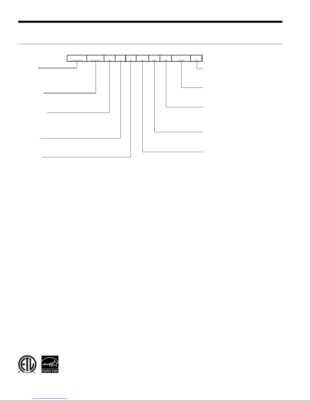
Model Nomenclature
1-3
NHW
4-6
0847H819810011A12B
Model
NHW = 5 Series High Temp
Hydronic Heat Pump
Capacity
084 = Dual Compressor, 84 MBtu/h
Operation
H = Heating Only
R = Reversible
Voltage
1 = 208-230/60/1
Controls
8 = FX10 std. no communication, with MUI
NOTE: MUI = Medium User Interface
13-14SS15
A
Vintage
A = Residential Cabinet
Non-Standard Option
SS = Standard
Water Connections
B = Back mounted connections
T = Top mounted connections
Heat Exchanger Option
A = Brazed Plate
IntelliStart Option
0 = None
3 = IntelliStart
®
All 5 Series 502W12 product is safety listed under UL1995 thru ETL and performance listed with AHRI in
accordance with standard 13256-2. The 5 Series 502W12 is also Energy Star rated.
4
General Installation Information
5 SERIES 502W12 INSTALLATION MANUAL
Safety Considerations
Installing and servicing air conditioning and heating
equipment can be hazardous due to system pressure and
electrical components. Only trained and qualified service
personnel should install, repair or service heating and air
conditioning equipment. When working on heating and
air conditioning equipment, observe precautions in the
literature, tags and labels attached to the unit and other
safety precautions that may apply.
Follow all safety codes. Wear safety glasses and work
gloves. Use quenching cloth for brazing operations. Have
fire extinguisher available for all brazing operations.
NOTE: Before installing, check voltage of unit(s) to ensure
proper voltage.
WARNING: Before performing service or
maintenance operations on the system, turn off
main power switches to the unit. Electrical shock
could cause serious personal injury.
WARNING: This heat pump is capable of
producing hot water up to 150°F. All exposed
piping surfaces shall be insulated to prevent
serious personal injury that can occur from
touching water piping.
Application
Units are not intended for heating domestic (potable) water
or swimming pools by direct coupling. If used for this type
of application, a secondary heat exchanger must be used.
Unit Location
Provide sufficient room to make water and electrical
connections. If the unit is located in a confined space,
provisions must be made for unit servicing. Locate the
unit in an indoor area that allows easy removal of the
access panels and has enough space for service personnel
to perform maintenance or repair. These units are not
approved for outdoor installation and, therefore, must be
installed inside the structure being conditioned. Do not
locate units in areas subject to freezing conditions.
WARNING: Do not store or install units in
corrosive environments or in locations subject
to temperature or humidity extremes (e.g. attics,
garages, rooftops, etc.). Corrosive conditions and
high temperature or humidity can significantly
reduce performance, reliability, and service life.
WARNING: To avoid equipment damage and
possible voiding of warranty, be sure that
properly sized strainers are installed upstream
of both brazed plate heat exchangers to protect
them against particles in the fluid.
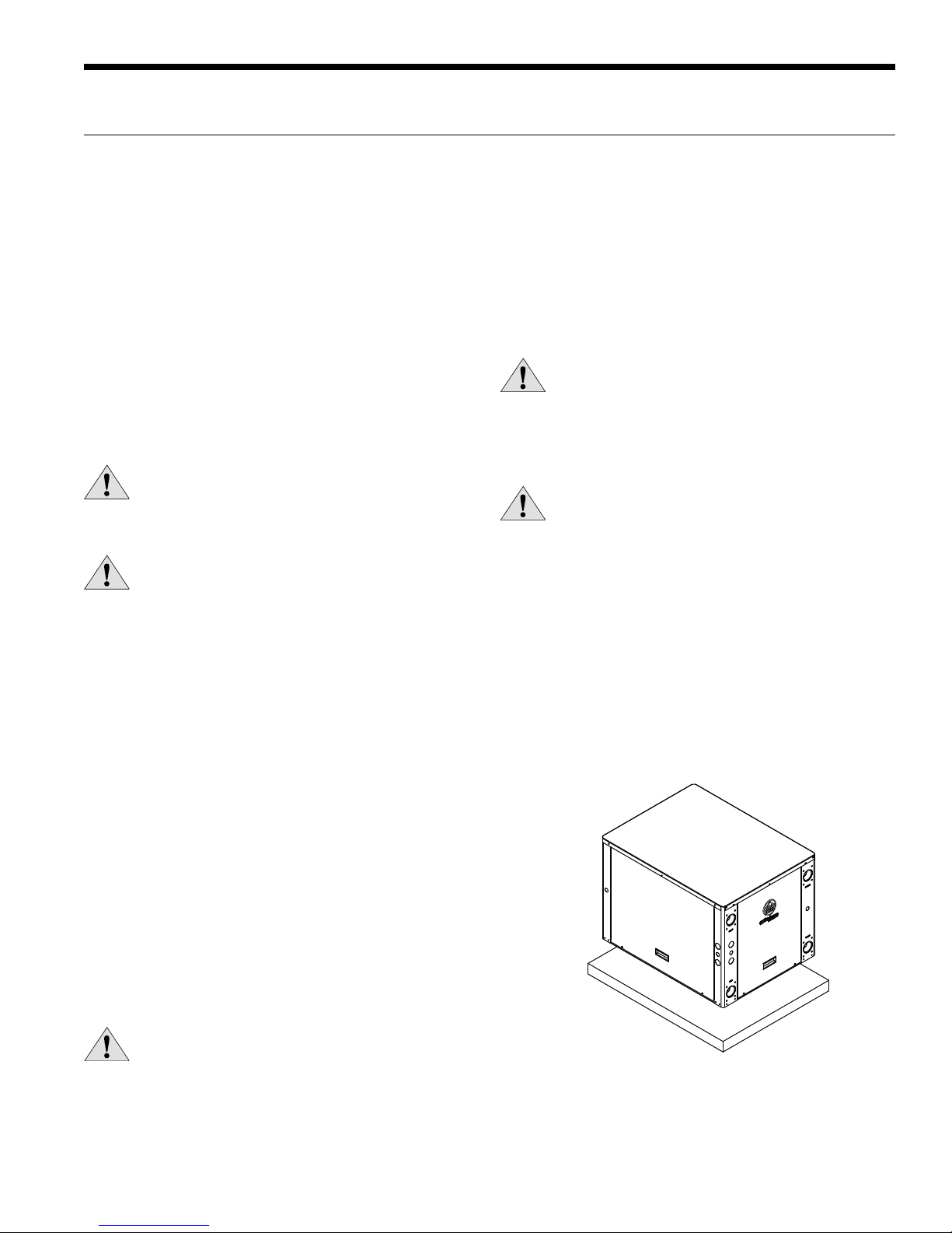
Mounting Units
Prior to setting the unit in place, remove and discard
both compressor hold down shipping bolts located at the
front of each compressor mounting bracket. Units should
be mounted level on a vibration absorbing pad slightly
larger than the base to provide isolation between the
unit and the floor. It is not necessary to anchor the unit to
the floor. Allow access to the front, back, and side access
panels for servicing.
Moving and Storage
Move units in the normal “Up” orientation as indicated by
the labels on the unit packaging. When the equipment
is received, all items should be carefully checked against
the bill of lading to ensure that all crates and cartons
have been received in good condition. Examine units for
shipping damage, removing unit packaging if necessary
to properly inspect unit. Units in question should also
be internally inspected. If any damage is observed, the
carrier should make the proper notation on delivery receipt
acknowledging the damage. Units are to be stored in a
location that provides adequate protection from dirt, debris
and moisture.
WARNING: To avoid equipment damage, do not
leave the system filled in a building without heat
during cold weather, unless adequate freeze
protection levels of antifreeze are used. Heat
exchangers do not fully drain and will freeze
unless protected, causing permanent damage.
DWP`ObW]\>OR;]c\bW\U
5
5 SERIES 502W12 INSTALLATION MANUAL
Field Connected Water Piping
General
Each unit is equipped with captive 1-1/4 in. [31.8 mm] FPT
water connections to eliminate ‘egg-shaping’ from use of a
backup wrench. For making the water connections to the unit,
a Teflon tape thread sealant is recommended to minimize
internal fouling of the piping. Do not over tighten connections.
NOTE: Units are factory run-tested using propylene
glycol. Prior to connecting piping to unit, thoroughly
flush heat exchangers.
The piping installation should provide service personnel
with the ability to measure water temperatures and
pressures. The water lines should be routed so as not to
interfere with access to the unit. The use of a short length
of high pressure hose with a swivel type fitting may simplify
the connections and prevent vibration.
Before final connection to the unit, the supply and return
hose kits must be connected, and the system flushed
to remove dirt, piping chips and other foreign material.
Normally, a combination balancing and close-off (ball) valve
is installed at the return, and a rated gate or ball valve is
installed at the supply. The return valve can be adjusted to
obtain the proper water flow. The valves allow the unit to
be removed for servicing. Both source as well as load fluid
piping must be at least as large as the unit connections on
the heat pump (larger on long runs).
Water Flow Rate
The proper water flow must be delivered to each unit
whenever the unit heats or cools. To assure proper flow,
the use of pressure/temperature ports is recommended
to determine the flow rate. These ports should be located
adjacent to the supply and return connections on the unit.
The proper flow rate cannot be accurately set without
measuring the water pressure drop through the refrigerantto-water heat exchanger (See Pressure Drop Table for water
flow and pressure drop information).
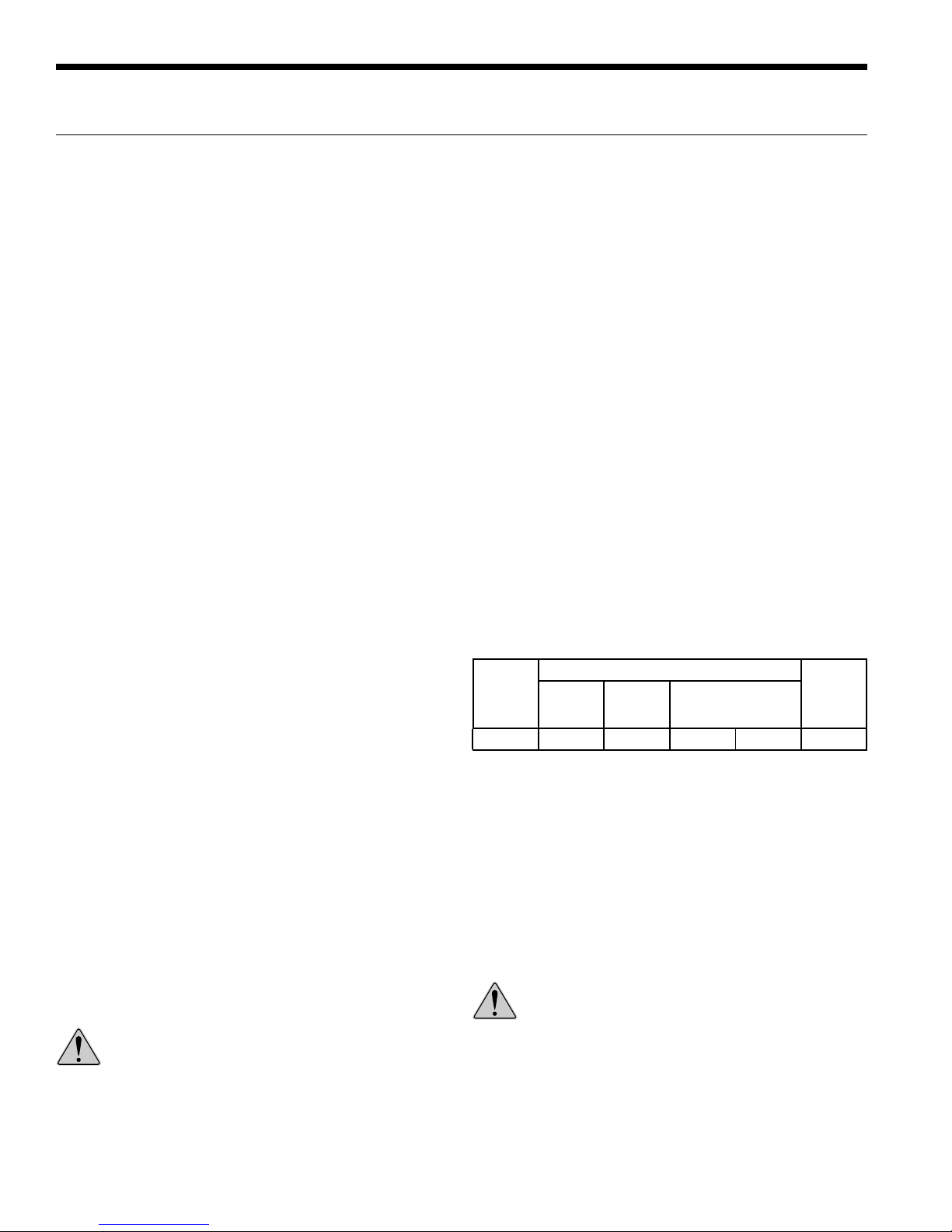
Load Flow Rate
The load flow on the 5 Series 502W12 should be 20 gpm
(typically the rated flow). Refer to the table below. This
flow rate is required especially when heating water to limit
the effects of the higher condensing temperatures of water
heating for radiant floor heating or domestic water use.
Source Flow Rate
The source flow can range between 15 and 25 gpm for earth
loops. For open loop well water systems the minimum flow
should be 15 gpm. In earth loop systems where entering
water temperatures are expected to be above 95°F, 25
gpm should be used. In well systems where the water
temperature is below 50°F, 20 gpm should be used to avoid
nuisance freeze detection trips.
Never use flexible hoses of a smaller inside diameter than
that of the water connection on the unit and limit hose length
to 10 ft. per connection. Check carefully for water leaks.
Load and Source Piping Connections
The 5 Series 502W12 has two connection options available.
Each kit is intended to connect one piping connection.
Therefore, two kits will be required for each unit. The kits can
be mixed for installer convenience, one on source and the other
on load
.
• CK5L - Kit includes a pair of forged brass street elbows
(1-1/4 in. MPT x 1-1/4 in. hose barb) with 1/4 in. pressure/
temperature plugs
• CK5L-XL - 1-1/4 in. rubber hose kit includes CK5L plus
two 8 ft. pieces of 1-1/4 in. rubber hose, a pair of 1-1/4 in.
hose barb x 1-1/4 in. XL style fittings, and stainless steel
hose clamps
• CK5L-XLS - 1-1/4 in. rubber hose kit includes all the same
items from CK5L-XL plus 1-1/4 in. 20 mesh bronze strainer
WARNING: All field installed piping and piping
connections must be rated for temperatures
greater than 160°F. Materials such as PVC, CPVC,
and DWV shall not be used.
Model
NHW084
Source Flow Rate (gpm)
Minimum
Open
Loop
15 20 20 25 25
Open
Loop
< 50°F
Closed Loop Range
(Min - Full Flow)
Load
Flow
Rate
(gpm)
Flushing
Flushing the system of debris is especially important in
brazed plate heat exchanger systems. These systems have
many small parallel flow paths in which debris can clog.
Initial flushing of the system can be accomplished in one
of two ways. First flushing the piping system toward the
strainer will allow the strainers to capture all debris prior the
heat exchangers and commissioning. Secondly a temporary
bypass can be included in the piping design so that the heat
pump itself can be bypassed during the initial flushing stage
with an external strainer gathering the debris.
CAUTION: Water piping exposed to outside
temperature may be subject to freezing.
6
Field Connected Water Piping cont.
Open Loop Well Water Systems
Installation of an open loop system is not recommended
unless water quality guidelines are met.
5 SERIES 502W12 INSTALLATION MANUAL
Earth Coupled Systems
All supply and return water piping should be insulated to
prevent excess condensation from forming on the water
lines. Ensure pumping system is capable of providing
adequate flow rate at the system pressure drop, 25 gpm
[1.58 L/s] (source side) is recommended. Antifreeze in the
loop is strongly recommended.
Heating with High Source Temperatures
Heating water with a water to water unit using high source
temperatures can lead to operating conditions that fall
outside of the system operating range. The condition
occurs when the loop (source) temperature exceeds 70°F
[21.1°C] with a full flow of 25 gpm [1.58 L/s]. Under this
scenario, the evaporating temperature can fall outside of
the compressor operating window.
To allow the system to operate correctly, restricting the
source side flow when the evaporating temperature
exceeds 55°F [12.7°C] is recommended. One way of
accomplishing this is to use a flow-restricting valve on the
source loop circuit that is controlled by the evaporating
temperature. Locate the sensing device on the refrigerant
inlet of the evaporator. In dual circuit systems, the company
recommends monitoring both circuits and controlling off
the sensor that reads the highest temperature.
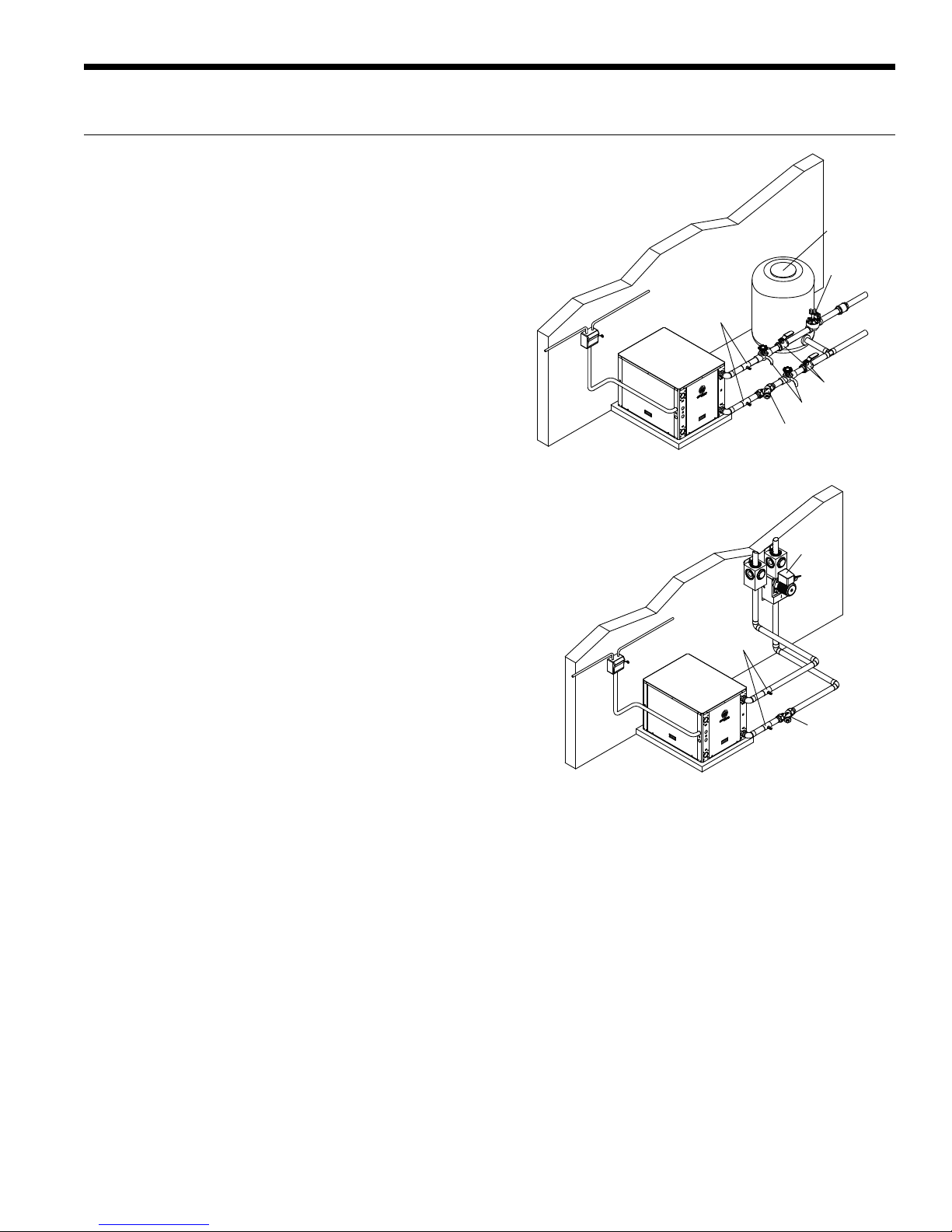
PT Ports
NHW
Open Loop Well Water Systems
PT Ports
NHW
Boiler Drain
Y-strainer
Flow
Center
Well Tank
Solenoid
Valve
Ball Valve
As an alternative to the evaporating temperature, the
suction line temperature can be monitored with the same
control capability. In this control, temperature should be a
maximum of 65°F [18.3°C].
A kit is available for this application, contact WaterFurnace
for support.
Y-strainer
Earth Coupled Systems
7
5 SERIES 502W12 INSTALLATION MANUAL
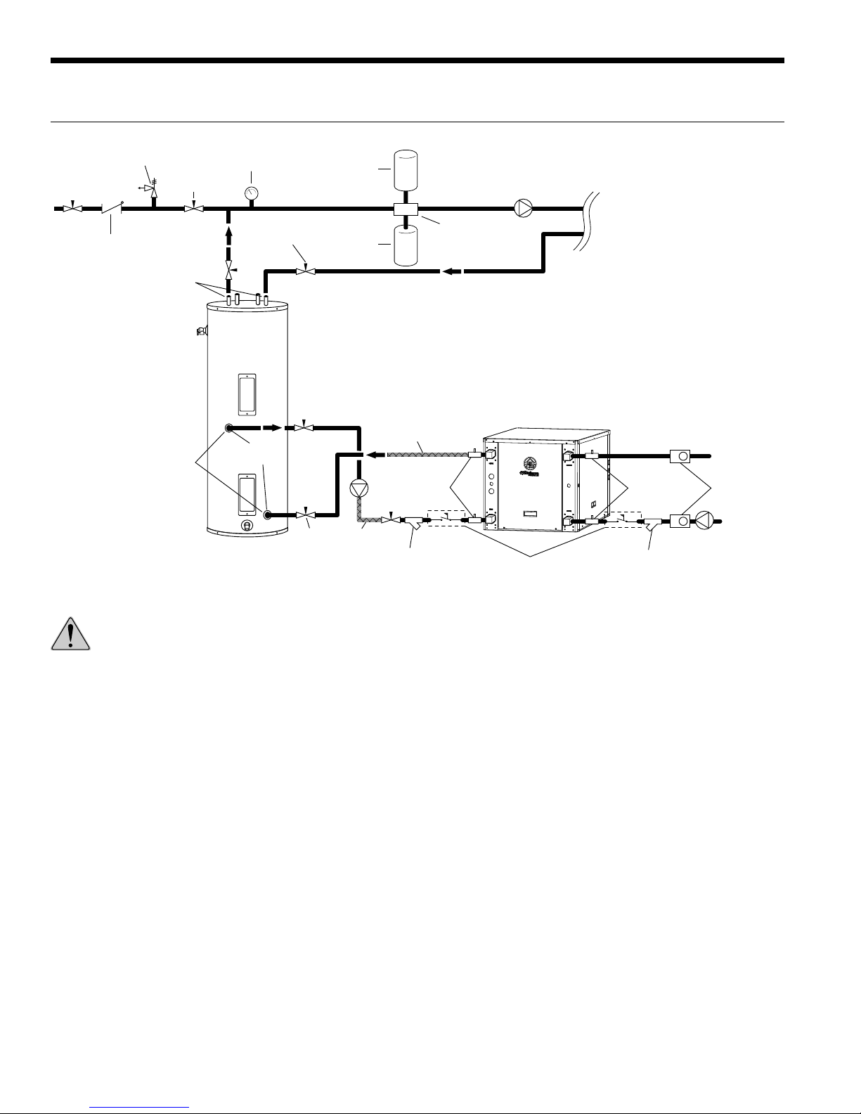
Typical Application Piping
30 PSI
RELIEF VALVE
Pressure
Reduction
Back Flow Preventer /
Pressure Relief Valve
Dielectric
Unions
Dielectric
Unions
NOTE: * A 30 PSI pressure relief valve
(Part No: SRV30) should be used in
hydronic applications.
Pressure
Gauge
Pressure
Reduction
GEO
STORAGE
TANK
1-1/2˝
FPT
Ball Valve
Air
Vent
Expansion
Tank
Hose Kit
(required to prevent
damage from fouling)
Hose Kit
P/T Ports
Y-Strainer
Air
Separator
LOAD PUMP
WaterFurnace
5 Series 502W12
Flow Switch
(recommended)
HYDRONIC
LOAD
P/T Ports
Y-Strainer
(required to prevent
damage from fouling)
Source OUT
3-Way Valves
Source IN
WARNING: When using a water storage tank thermostat the tank temperature should not be set higher than the
maximum entering water temperature of the heat pump. This will limit the possibility of the heat pump from
operating outside of the performance table.
8
Water Quality
5 SERIES 502W12 INSTALLATION MANUAL
General
Reversible chiller systems may be successfully applied in a
wide range of commercial and industrial applications. It is the
responsibility of the system designer and installing contractor
to ensure that acceptable water quality is present and that all
applicable codes have been met in these installations.
Water Treatment
Do not use untreated or improperly treated water. Equipment
damage may occur. The use of improperly treated or
untreated water in this equipment may result in scaling,
erosion, corrosion, algae or slime. The services of a qualified
water treatment specialist should be engaged to determine
what treatment, if any, is required. The product warranty
specifically excludes liability for corrosion, erosion or
deterioration of equipment.
The heat exchangers in the units are 316 stainless steel plates
with copper brazing. The water piping in the heat exchanger
is steel. There may be other materials in the building’s piping
system that the designer may need to take into consideration
when deciding the parameters of the water quality.
If an antifreeze or water treatment solution is to be used, the
designer should confirm it does not have a detrimental effect
on the materials in the system.
Contaminated Water
In applications where the water quality cannot be held to
prescribed limits, the use of a secondary or intermediate heat
exchanger is recommended to separate the unit from the
contaminated water.
The following table outlines the water quality guidelines for unit
heat exchangers. If these conditions are exceeded, a secondary
heat exchanger is required. Failure to supply a secondary heat
exchanger where needed will result in a warranty exclusion for
primary heat exchanger corrosion or failure.
Strainers
These units must have properly sized strainers upstream of
both brazed plate heat exchangers to protect them against
particles in the fluid. Failure to install proper stainers and
perform regular service can result in serious damage to the
unit, and cause degraded performance, reduced operating
life and failed compressors. Improper installation of the unit
(which includes not having proper strainers to protect the
heat exchangers) can also result in voiding the warranty.
Field supplied strainers with 420-840 microns are
recommended, with 500 microns being the optimum choice.
The strainers selected should have a mesh open area of at
least 39 cm2 for each unit being serviced by the strainer. Using
strainers with a smaller amount of open area will result in the
need for more frequent cleaning.
Strainers should be selected on the basis of acceptable
pressure drop, and not on pipe diameter. The strainers
selected should have a pressure drop at the nominal flow rate
of the units; low enough to be within the pumping capacity of
the pump being used.
WARNING: Must have intermediate heat
exchanger when used in pool applications.
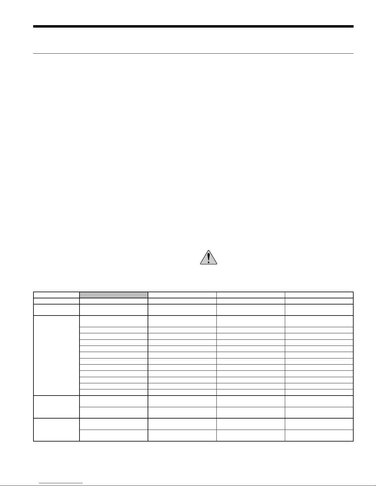
Water Quality Guidelines
Material Copper 90/10 Cupronickel 316 Stainless Steel
pH Acidity/Alkalinity
Scaling
Corrosion
Iron Fouling
(Biological Growth)
Erosion
NOTES: Grains = ppm divided by 17
mg/L is equivalent to ppm
Calcium and
Magnesium Carbonate
Hydrogen Sulfide
Chlorine Less than 0.5 ppm Less than 0.5 ppm Less than 0.5 ppm
Chlorides Less than 20 ppm Less than 125 ppm Less than 300 ppm
Carbon Dioxide Less than 50 ppm 10 - 50 ppm 10 - 50 ppm
Ammonia Less than 2 ppm Less than 2 ppm Less than 20 ppm
Ammonia Chloride Less than 0.5 ppm Less than 0.5 ppm Less than 0.5 ppm
Ammonia Nitrate Less than 0.5 ppm Less than 0.5 ppm Less than 0.5 ppm
Ammonia Hydroxide Less than 0.5 ppm Less than 0.5 ppm Less than 0.5 ppm
Ammonia Sulfate Less than 0.5 ppm Less than 0.5 ppm Less than 0.5 ppm
Total Dissolved Solids (TDS) Less than 1000 ppm 1000 - 1500 ppm 1000 - 1500 ppm
LSI Index +0.5 to -0.5 +0.5 to -0.5 +0.5 to -0.5
Iron, FE
Bacterial Iron Potential
Iron Oxide
Suspended Solids
Threshold Velocity
(Fresh Water)
Less than 0.5 ppm (rotten egg
smell appears at 0.5 ppm)
Sulfates Less than 125 ppm Less than 125 ppm Less than 200 ppm
2
+ (Ferrous)
Less than 1 ppm, above this
level deposition will occur
Less than 10 ppm and filtered
for max. of 600 micron size
7 - 9 7 - 9 7 - 9
(Total Hardness)
less than 350 ppm
< 0.2 ppm < 0.2 ppm < 0.2 ppm
< 1.8 m/sec < 1.8 m/sec < 1.8 m/sec
(Total Hardness)
less than 350 ppm
10 - 50 ppm Less than 1 ppm
Less than 1 ppm, above this
level deposition will occur
Less than 10 ppm and filtered
for max. of 600 micron size
(Total Hardness)
less than 350 ppm
Less than 1 ppm, above this
level deposition will occur
Less than 10 ppm and filtered
for max. of 600 micron size
9
2/22/12
5 SERIES 502W12 INSTALLATION MANUAL
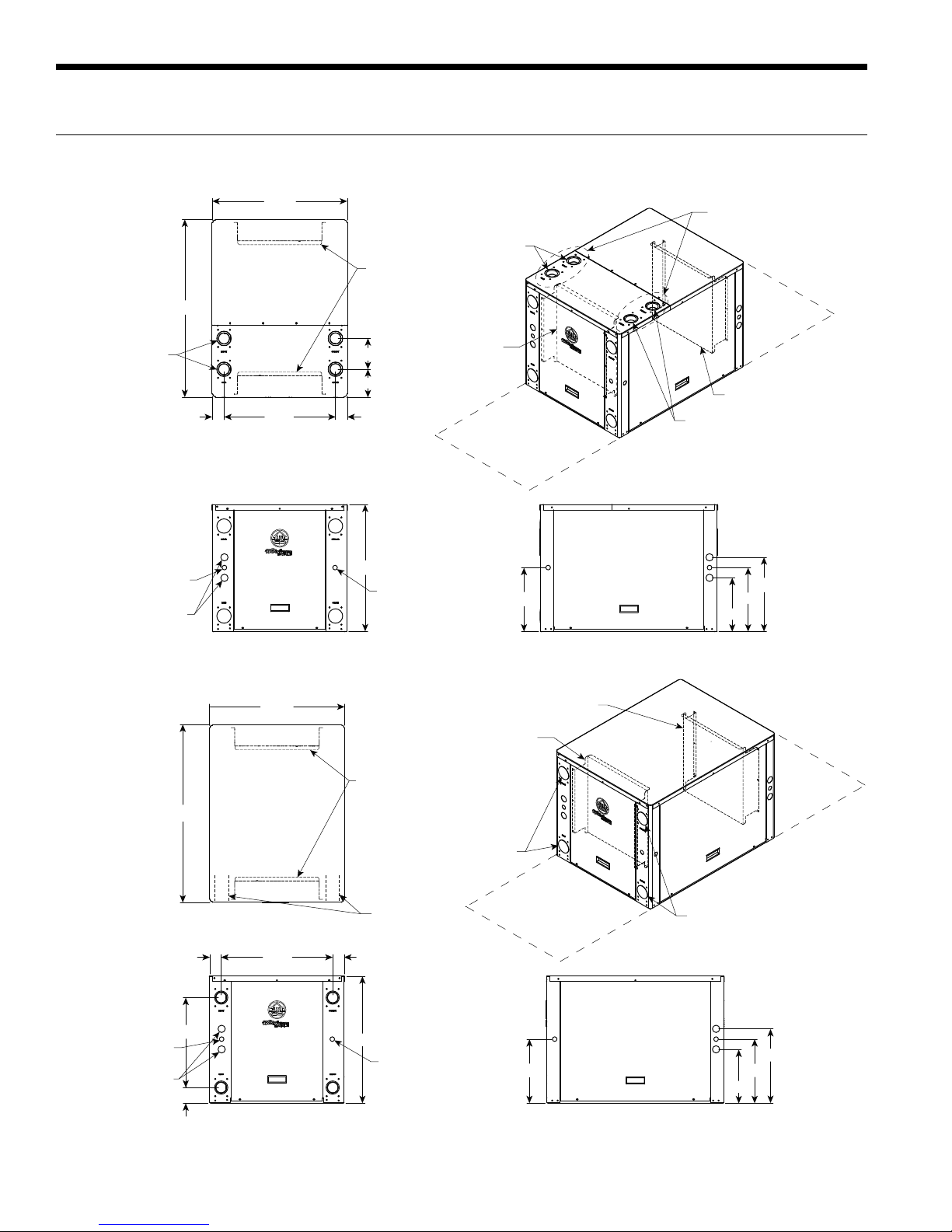
Dimensional Data
NHW084 - Top Waterline Configuration
!!$
E/B3@:7<3A
:=ED=:B/53
%&9<=19=CB
:7<3D=:B/53
!&9<=19=CBA
$
##&
AB/<2/@2
=>B7=</:
%
1=<B@=:0=FA67>A
AB/<2/@2=>>=A7B3
=4E/B3@:7<3A0CB
6/A473:2=>B7=<
B=03AE7B1632
#&
# &
$
"
1=<B@=:0=F
=>B7=</::=E
D=:B/53
%&9<=19=CB
:=/2
=>B7=<
/:B3@</B3
A3@D713/113AA
=>B7=</:
B=>E/B3@
1=<<31B7=<A
>@7;/@G
A3@D713
/113AA
1=<B@=:0=F
A=C@13
"#
&
NHW084 - Back Waterline Configuration
##&
AB/<2/@2
1=<B@=:0=FA67>A
AB/<2/@2=>>=A7B3
=4E/B3@:7<3A0CB
6/A473:2=>B7=<
B=03AE7B1632
E/B3@:7<3A
$
"
=>B7=</::=ED=:B/53
%&9<=19=CB
:=ED=:B/53
%&9<=19=CB
:7<3D=:B/53
!&9<=19=CBA
!!#'
$
%
'$
=>B7=</:
$
1=<B@=:0=F
1=<B@=:0=F
=>B7=<
:=/2
/:B3@</B3
A3@D713/113AA
>@7;/@G
A3@D713
/113AA
A=C@13
"#
&
10
 Loading...