

Wascomat WS3 230-340-470-670 H, WSB3 230-340-470-670 H, WS3 230 H, WS3 340 H, WS3 470 H Instruction Handbook Manual
...
08100226gb
WASHER-EXTRACTORS
WS3 230-340-470-670 H
WSB3 230-340-470-670 H
INSTRUCTION HANDBOOK

Notice
Date Page
01201055
INSTRUCTION
HANDBOOK
General instructions
General..................................................... 1/1
Precautions for use...................................1/2
Environmental information........................ 1/3
Preliminary instructions ............................ 1/4
Locking and tagging procedure ................ 1/5
Handling/Weight
Handling ................................................... 1/6
Packing - Weight ...................................... 1/7
Technical characteristics
Technical characteristics .......................... 1/8
Sound level.............................................. 17/8
Label of energetic performances ............. 17/8
Installation/Putting into service
Installation ................................................ 1/9
Working place lighting .............................. 2/9
Supplies.................................................... 2/9
Mechanical installation ............................. 3/9
Fitting of the safety flanges....................... 4/9
Fitting of the filling angles ......................... 5/9
Assembling of the partition for
barrier machine.........................................6/9
Water connections.................................... 7/9
Steam connection..................................... 8/9
Drain connection......................................10/9
Air vent connection .................................. 11/9
Installation of the gas exchanger............. 11/9
Connection of the evacuation pipe of
the gas exchanger ................................... 13/9
Gas connection........................................15/9
Liquid detergents connection...................22/9
Electrical connection................................24/9
Remove of the transport locks fitted ........ 29/9
Operating inspection
Manual operation..................................... 1/10
Automatic operation.................................2/10
Machine operation
Auxiliary control ....................................... 1/11
Automatic operation.................................3/11
Detergent dispenser ................................ 5/11
To run a wash program ........................... 6/11
The "move back" key............................... 6/11
To start the wash program.......................6/11
To start a wash program from the
program library .......................................10/11
To change parameters in the current
program step ..........................................13/11
Rapid advance........................................14/11
Pages/Chapters
The manufacturer reserves the right to modify construction and equipment characteristics.
Table of contents
0401
0
0
Pages/Chapters
Show weight ...........................................15/11
Pause .....................................................17/11
Manual operation during a program .......18/11
Text.........................................................24/11
To change the wash program after
program operation has commenced.......25/11
To change temperature scale °C/ °F ......26/11
Auto restart .............................................27/11
Manual operation
To select a manual operation .................28/11
Motor/door ..............................................29/11
Water/drain.............................................30/11
Heating ...................................................31/11
Detergent signals and water flushing .....32/11
At the end of the wash............................34/11
Statistics
To select "statistics"................................35/11
Resetting statistic registers.....................37/11
Automatic weighing
Scale adjustments ..................................42/11
ON/OFF and pause
On/off and pause by exterior signals ......53/11
Memory card
General introduction ...............................54/11
To select the "Memory card" function.....55/11
To run a wash program straight from
a memory card........................................58/11
To copy a program from a memory card
to the machine's program control unit.....59/11
To copy a program from the program
control unit to a memory card .................61/11
To delete a program on a
memory card...........................................63/11
To delete all programs on a
memory card...........................................64/11
Weighing equipment.................................65/11
HACCP option ...........................................76/11
Safety
Safety ...................................................... 1/12
Maintenance
Operating incidents.................................. 1/13
Preventive maintenance .......................... 1/14
Electric diagrams
Electric diagrams ..................................... 1/15
Appendices
Convertion measurement units................ 1/16
Washing symbols .................................... 2/16
Gas exchanger (25 kW)........................... 3/16
Notice
Date Page
01201055
INSTRUCTION
HANDBOOK
0300 1
1
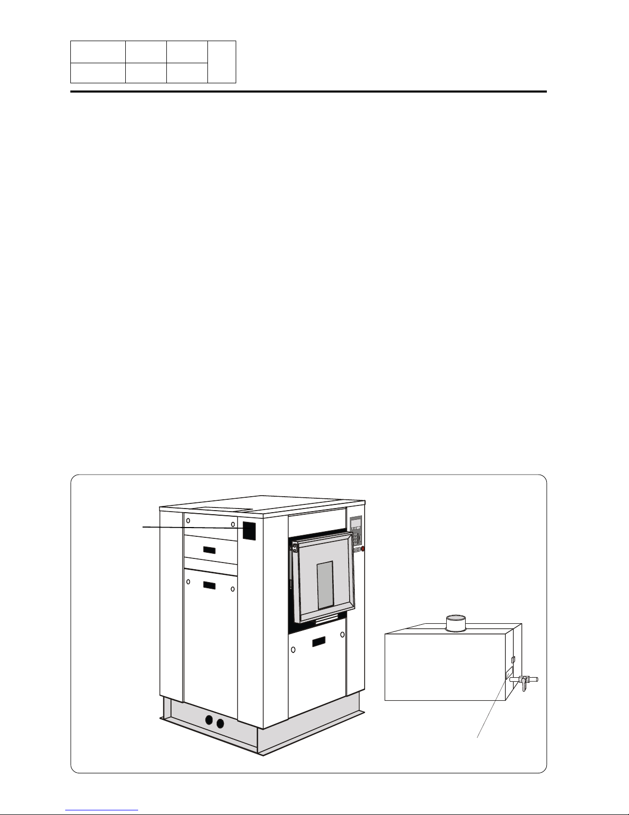
1. General
Identification
plate
General instructions
The machines described in this handbook have a washing capacity of 229, 338, 467 or 668
litres according to their type.
They are washer-extractors designed to meet the most severe requirements.
They are designed to be installed in hotels, laundries, hospitals or collectivities.
The suspension device mounted with springs and shock absorbers limits to the maximum
ground vibrations.
A important G factor guarantees the highest extraction quality for your linen.
These machines also exist in barrier version allowing the respect of linen's hygiene rules.
D0630/434
Adjustment label
GAS EXCHANGER

Notice
Date Page
01201055
INSTRUCTION
HANDBOOK
1199 2
1
1. General
1
2
3
45
6
7
89
0
During a wash : "Pause" key.
Before and after a wash, and during programming : "Move
back key".
By pressing this key repeatedly you can move backwards
through the menus you have navigated through. This will
always bring you back to the menu shown on the display in
this illustration.
Function keys.
The functions of these keys change, depending on
which menu or part of a menu you are using. Their
current functions at any time are shown on the
display immediately above each key.
Card reader for
memory cards
Display screen
Numeric keyboard
This washer extractor is controlled by a microprocessor-based program control unit placed on
the loading side. There are many advantages to this equipment, including :
•Timing, levels and temperatures are controlled with great precision and flexibility.
• The large display screen means that detailed information on wash programs, machine status
and operations, wash times and temperatures can be accessed in plain language
• It is possible for the user to create new wash programs, and to adapt programs with great
precision, on the basis of experience and to suit various types of textile, degrees of soiling
etc.
• a very high level of machine safety through continuous monitoring and built-in safety
interlocks.
• The program control unit has a reader for "smart cards". These are cards the size of a credit
card which contain a memory chip. Smart cards allow the user to :
- transfer wash programs between a PC and the washer extractor, or from one washer
extractor to another
- run programs straight from a card
• Great flexibility during program operation :
- rapid advance both forwards and backwards in the program
- the user can change temperatures, program module lengths and extraction speeds
directly, during program operation
- change to running a different wash program, at any time during program operation of the
washer extractor.
4221 3651
RUN A W ASH PROGR AM
GO TO THE MENU

Notice
Date Page
01201055
INSTRUCTION
HANDBOOK
1298 3
1
1. General
A very high working safety level of the machine is achieved thanks to a continuous monitoring
and built-in safety devices.
Even the compound textile fabrics can be washed at a high temperature with no crumpling risk
thanks to a special cooling process before the rinsing cycle.
In order to avoid an excessive mechanical fatigue during the hydro-extraction process, the
machine is equipped with an unbalance detector. If the latter detects the least unbalance of the
load, the hydro-extraction cycle is interrupted and the machine fills with water to make a new
distribution of the linen possible.
The machine then resumes the distribution speed and another hydro-extraction cycle begins.
The machine can also be controlled sequence by sequence and is equipped with a keyboard
for the manual control of certain functions.

Notice
Date Page
01201055
INSTRUCTION
HANDBOOK
0700 1
2
2. Precautions for use
Precautions for use
. The machine should not be used by children.
. The machine is designed for "water washing" of textile only.
. This machine is for professional use and must be used exclusively by qualified personnel.
. It is forbidden to wash textiles soaked with solvents.
. In case of a gas heated machine, do not assemble the machine on premises containing a
dry cleaning machines or other similar machines.

Notice
Date Page
01201055
INSTRUCTION
HANDBOOK
0401 1
3
3. Environmental
information
Environmental information
Concerned by providing the end user with useful and necessary environmental information, we
wish to precise :
. Data about energetic consumptions, wastes (atmospheric and liquid) and sound level are
indicated in the paragraph "Technical characteristics".
. The running of this machine requires the use of detergents which draining in the nature can
have a significant environmental impact. So, we do recommend to only use, with agreement
of the manufacturers, the quantities of detergents strictly necessary.
. This machine is fully dismantle.
. This machine is free from any asbestos.
. Our machine packing complies with the provisions of rule 98-639 dated July 20th 1998
regarding environmental demands.
For additional information, do not hesitate to consult our environmental department.
Notice
Date Page
01201055
INSTRUCTION
HANDBOOK
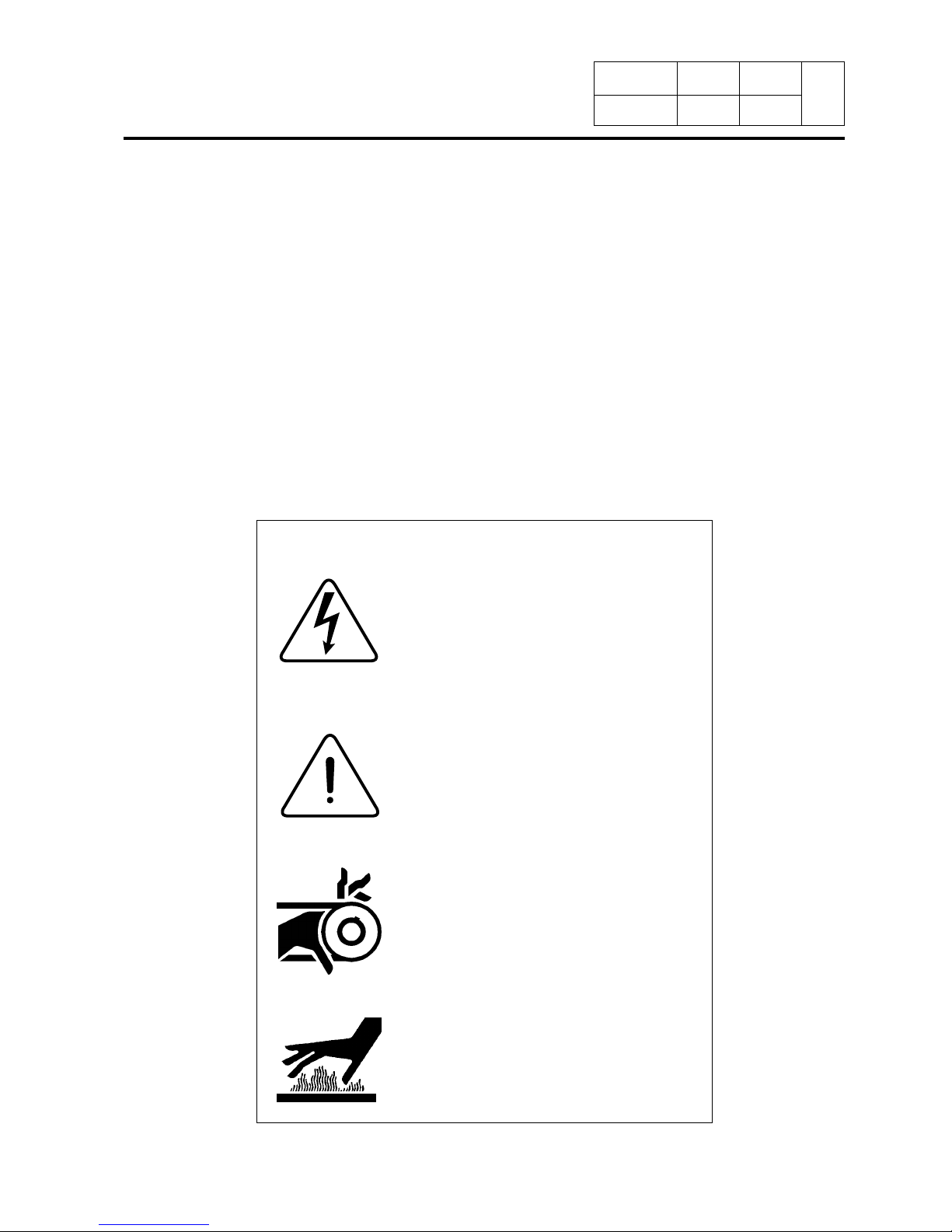
A flash of lightning with an arrow at its
end displayed inside an equilateral triangle, warns the user about the presence of uninsulated "dangerous current" sufficient in intensity to cause
electrocution.
An exclamation mark inside an equilateral triangle offers the user important advice about usage, servicing and
hazardous conditions.
This symbol warns the user that there
are mechanisms inside the machine
which can be dangerous. The protective housing must be in place during
use.
This symbol warns the user of the presence of high temperatures which could
cause severe burns. Some surfaces
can reach close to 200 °C (392 °F).
Explanation of graphic symbols
0401 1
4
4. Preliminary
instructions
Preliminary instructions
Before any use, it is compulsory to read the instruction handbook.
Users must have learnt how the machine operates.
The identification plate is placed on the left hand side of the machine.
In order to prevent any risk of fire or explosion, flammable products should never be used to
clean the machine.
Any repair or maintenance intervention should be carried out by qualified personnel only.
Detergents used in laundry are particularly agressive. No stainless steel is able to resist their
corrosive actions. Detergent dispenser must consequently be considered as wearing parts
likely to be replaced.

Notice
Date Page
01201055
INSTRUCTION
HANDBOOK
1199 2
4
4. Preliminary
instructions
SAFETY
The mechanical and electrical installation
of the machine should only be done by
qualified personnel.
CAUTION
Do not use the machine unless it is plugged
into a correctly earthed power socket complying with standards in force.
CAUTION
For your personal safety, never use the
machine without the protective housings.
CAUTION
Disconnect the machine electrical power
supply before doing any repair or servicing work.
SAFETY
This machine should be installed in conformance to the health and safety regulations, and only used in a sufficiently aerated area.
Check the instructions before installing or
using the machine.
Disconnect all the sources of energy before any intervention on the machine.
Never try to open the drum door before the complete stop of the cage.
The safety devices of the drum door(s) should in no case be made inoperative.
The machines comply with the European Directive EMC (Electromagnetic Compatibility). They
have been tested in laboratory and approved as such. It is so prohibited to add wires or non
shielded electric cables in the cabinets, strands or cables' troughs.
Considering that the volume of the cage is superior to 150 liters, the standard kept for the
electric part is the IN 60204.
Notice
Date Page
01201055
INSTRUCTION
HANDBOOK
1101 3
4
4. Preliminary
instructions
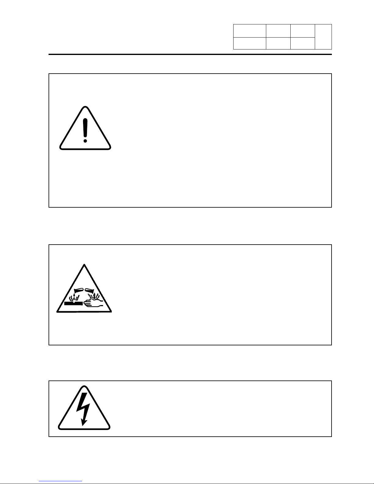
The use and handling of chemical products such as detergent, chlorine, acids, antiliming agents etc... may create hazards for health
and environment ; the following precautions should be taken.
- Do not breathe the dusts or steam.
- Avoid contact with skin or eyes (may cause burns).
- In case of important spillage, wear a protecting mask, gloves, and
eye protectors.
- Handle with care.
- Consult the use and first aid advice on the packings.
- Do not dispose pure products in the environment.
The machine can work without the protective casing when the electric supply is not cut off.
Interlock the main isolating switch with a padlock.
Close the steam or gas inlet valves.
Ensure that the machine is not loaded beyond its nominal capacity
(see "Specific load" in the instruction booklet’s technical characteristics).
An excessive load has consequences for the lifetime of the machine’s organs, as follows:
· Rapid destruction of the suspension elements (springs, shock
absorbers);
· Excessive fatigue of motorisation elements (engine, belt);
· Rapid reduction of lifetime of drum bearings (rolling bearings);
· Opening and destruction of drum doors and tank doors during
oil dehydration.
This is particularly important for your safety and that of others.
The consequence is an immediate cancellation of the warranty.

Notice
Date Page
01201055
INSTRUCTION
HANDBOOK
1298 4
4
4. Preliminary
instructions
Distributor Letter
Chemical System Responsibility
Disclaimer
The following policy should be considered and understood as a warranty/disclaimer to customers
operating textile care installations where liquid supply (chemical) systems use or may use peristaltic
pumps to inject supplies into equipment.
To Whom it May Concern :
We, the undersigned, accept no responsibility for loss or damage when, during periods of non-use,
concentrated chemicals leak, spray or "dribble" onto any part of our machines or their contents.
It is well known that many pumped liquid chemical systems tend to permit concentrated chemicals to
dribble out of the injection tubes when the system has not been used for relatively long periods of
time – as after working hours and during weekends. This puts highly concentrated corrosive chemicals in direct contact with dry stainless steel surfaces and often directly on any textiles left in the
machine. Chemical deterioration (rusting) of the stainless steel and damage to the textiles is the
inevitable result.
It is absolutely useless to flush the affected sites after each injection because the harmful dribble
always occurs later – after the machine is no longer in use. One seemingly foolproof solution for
"dribbling chemicals" (which we highly recommend but obviously cannot guarantee) is to locate the
chemical tanks and pumps well below the injection point on the machine (so the contents of the
injection tube(s) cannot siphon into the machine) and to completely purge the just-used chemical
injection tube(s), or manifold, with fresh water after every injection so that only fresh water (which
cannot cause a problem) can dribble out. Naturally, this – or any other solution – is the sole responsibility of the pump and/or chemical supplier (not the machine manufacturer).
Additionally, external chemical leakage is dangerous to personal health and safety, and will also
cause severe damage to machines and/or their surroundings. The installer and/or user of the chemical injection system must make sure there are no external chemical leaks and that excessive pressure can never build up in any chemical delivery tube, because excessive pressure can burst the
tube, or disconnect it from the machine, and spray dangerous concentrated chemicals about the
premises.
The machinery manufacturer is not, and cannot be, responsible for compliance with the
above.
Notice
Date Page
01201055
INSTRUCTION
HANDBOOK
1298 1
5
5. Locking and
tagging procedure
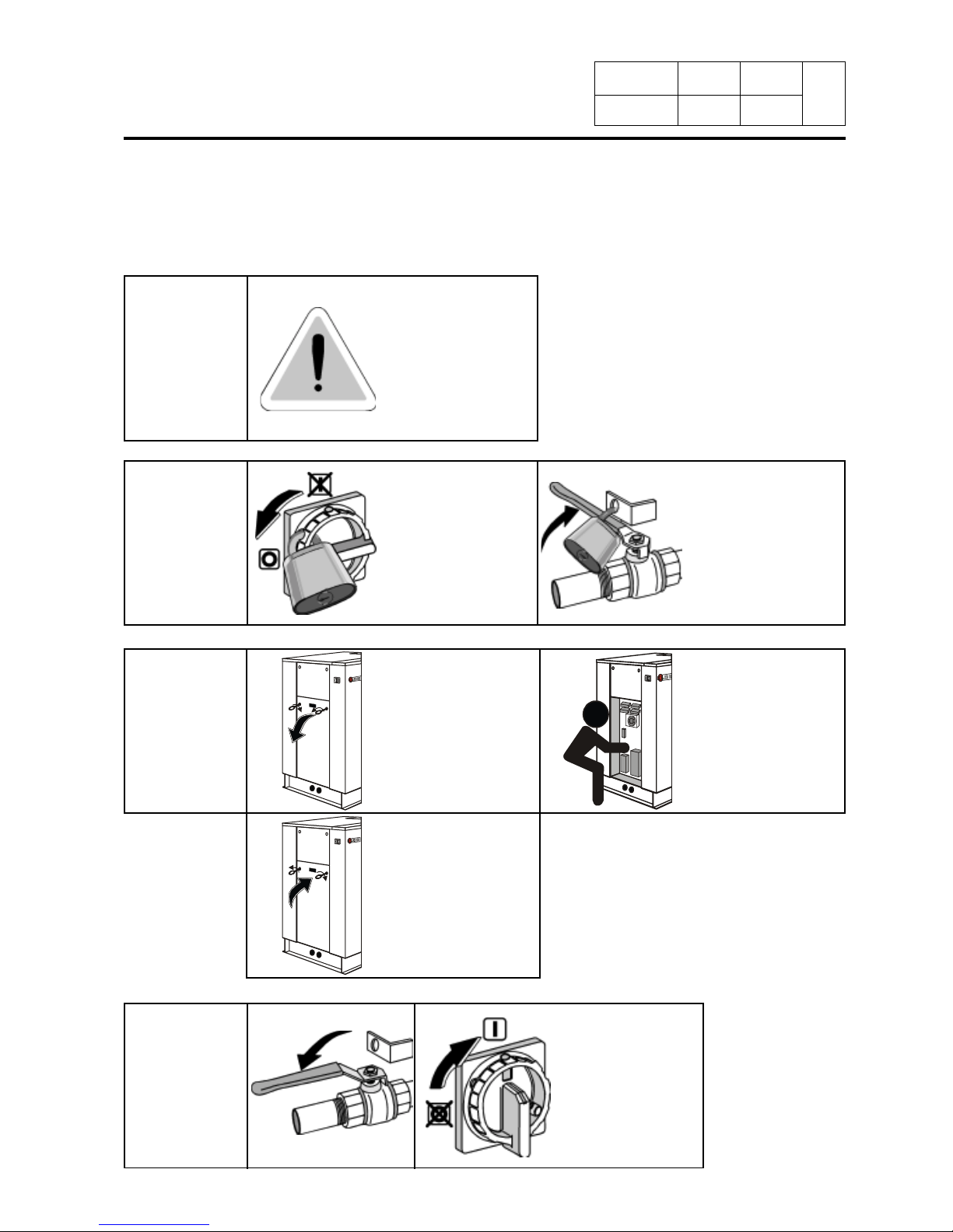
Locking and tagging procedure
1
2
3
4
A red insert at the beginning of this instruction handbook schematically shows the locking and
tagging procedure described below. If you wish, you can detach this insert and display it close
to the machine to remind maintenance personnel of the safety instructions.
Put the main switch
to Off and lock the
handle with a padlock
in one of the three
holes provided for
this purpose.
Always respect items
2, 3 and 4 carefully
before doing any repair or maintenance
work on the machine.
Open the fixed
protectors (casings,
doors) with the key
provided or a special
tool.
Close and carefully
lock the fixed
protectors.
Unlock the stop
valves and the
main switch.
Do the maintenance.
Close the stop valves for
the other supplies
(steam, gas, thermal
fluid, compressed air)
to stop and lock their
handle with a padlock.
Notice
Date Page
01201055
INSTRUCTION
HANDBOOK
1298 1
6
6. Handling
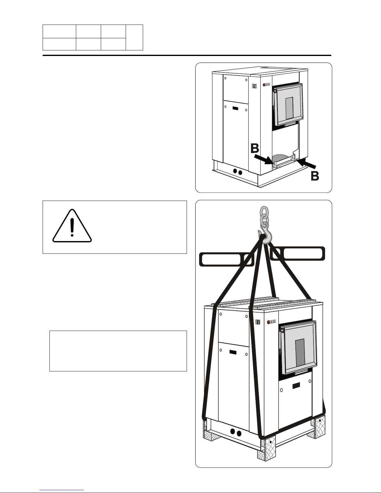
1/ Lifting with handling straps
Lifting in that case can only be done with
handling straps (minimum capacity 1000
daN) which bear weight of the machine.
Nota : in order to avoid bending of the
machine's casings, make sure to place
the lifting straps at each end of the
wooden planks.
Handling
D0604
1000 daN
1000 daN
Before any handling, check that the four
transport locks fitted are still in place and
well-tightened.
To do so, remove the front and rear casings
and check presence of four locks (B).
D0650
SAFETY
It is obligatory that all
these operations are
undertaken by handling
specialists.

Notice
Date Page
01201055
INSTRUCTION
HANDBOOK
1298 2
6
D0603
2/ Lifting with a fork-lift truck
This can be carried out from the front or
back, at the centre of the machine.
CAUTION
You should never handle the machine in
its longitudinal side (any other than shown
on the drawing below) with a fork-lift truck.
Important risk of parts deterioration for
those fixed under the machine.
OK
3/ Ground moving
The machine frame is made up of two parallel parts, making ground moving possible by
means of rollers.
D0659
6. Handling
Notice
Date Page
01201055
INSTRUCTION
HANDBOOK
1298 3
6
6. Handling
7
4
0
3
2
1
4
6
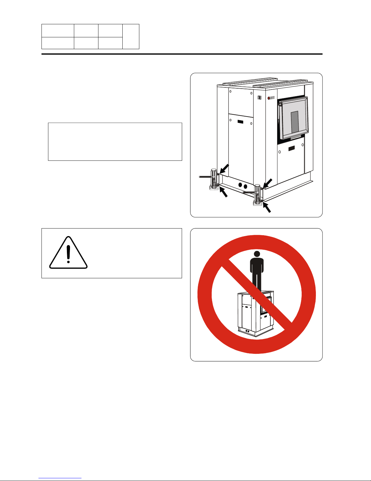
CAUTION
In order to avoid any bending of casings, you should
never climb and stand on
top of the machine.
4/ Lifting with a jack
Lifting in this case can only be done with a
jack (minimum capacity 500 daN) which can
bear the machine's weight.
Nota : in order to avoid the bending of
the sole, make sure to place the lifting
jack at each corner of the machine at
point A or B.
D0671
A
B
B
A
Notice
Date Page
01201055
INSTRUCTION
HANDBOOK
0102 1
7
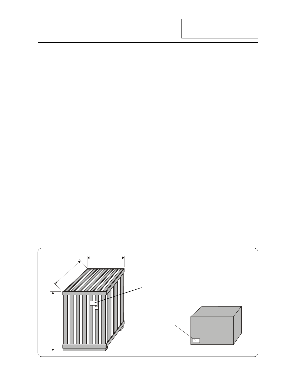
7. Packing - Weight
Packing
Packing dimensions in mm/inch Size A Size B Size C
Washer extractor Type 230 standard 1180/46.5 1230/48.4 1840/72.4
Washer extractor Type 230 barrier 1180/46.4 1230/48.4 1840/72.4
Washer extractor Type 340 standard 1180/46.4 1450/57 1840/72.4
Washer extractor Type 340 barrier 1180/46.4 1450/57 1840/72.4
Washer extractor Type 470 standard 1180/46.4 1760/69.3 1840/72.4
Washer extractor Type 470 barrier 1180/46.4 1760/69.3 1840/72.4
Washer extractor Type 670 standard 1180/46.4 2180/85.8 1840/72.4
Washer extractor Type 670 barrier 1180/46.4 2180/85.8 1840/72.4
Weight
Weight in kg/lb (machine + crate) Gas Electric Steam/T.F
Washer extractor Type 230 standard 775/1709 775/1709 775/1709
Washer extractor Type 230 barrier 775/1709 775/1709 775/1709
Washer extractor Type 340 standard 890/1963 890/1963 890/1963
Washer extractor Type 340 barrier 890/1963 890/1963 890/1963
Washer extractor Type 470 standard 1090/2404 1090/2404 1090/2404
Washer extractor Type 470 barrier 1090/2404 1090/2404 1090/2404
Washer extractor Type 670 standard 1195/2636 1195/2636 1195/2636
Washer extractor Type 670 barrier 1195/2636 1195/2636 1195/2636
Identification plate
(for gas machine only)
A
B
C
D0660/776
Adjustment label
GAS
EXCHANGER
Notice
Date Page
01201055
INSTRUCTION
HANDBOOK
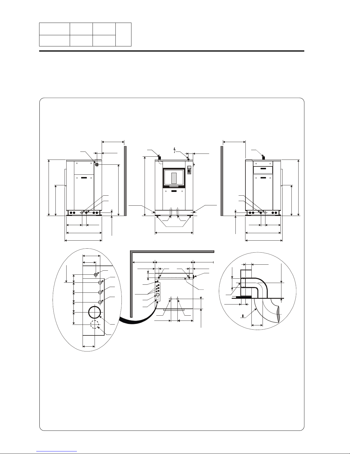
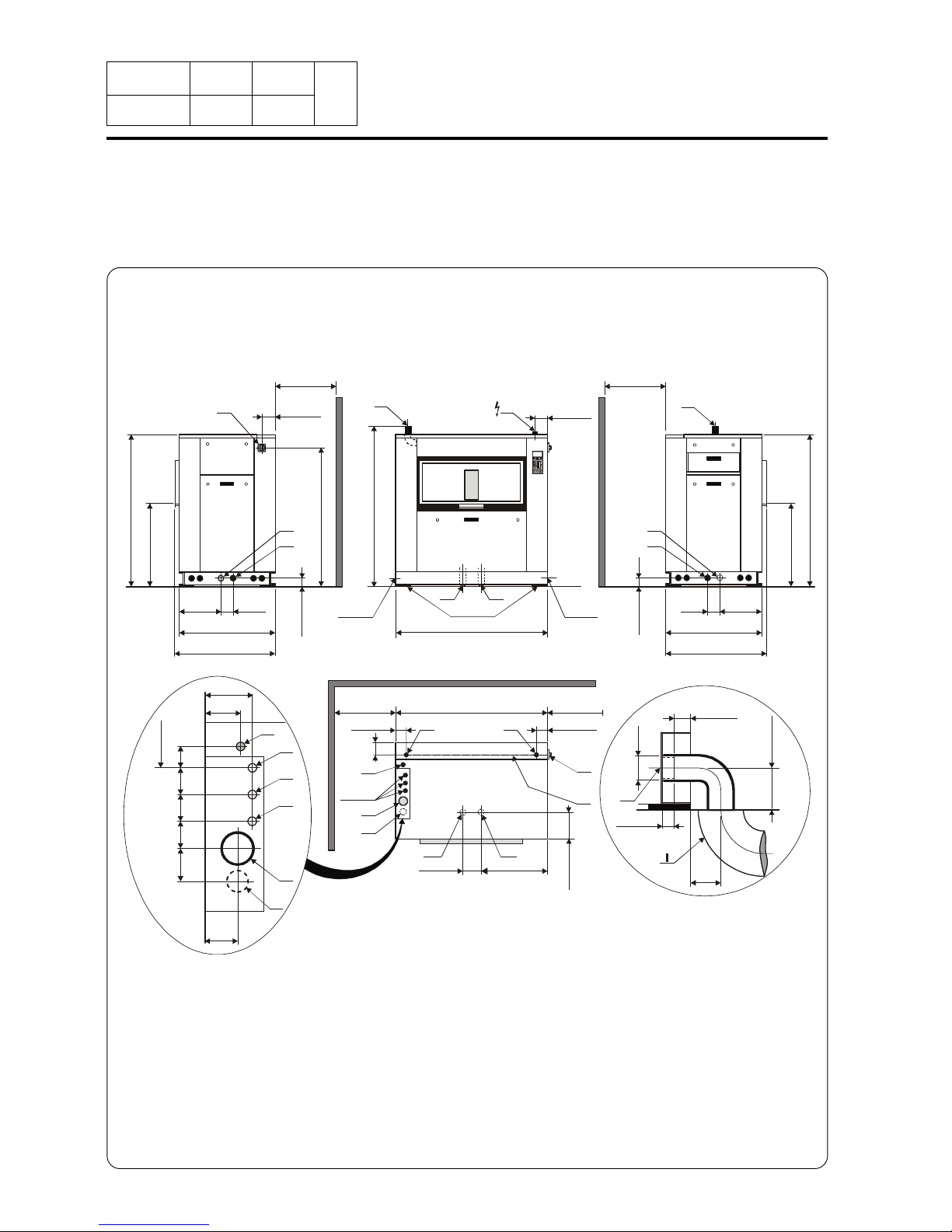
Front view
Top view
Right view Left view
Example of
drain connection
0999 1
8
8.Technical
characteristics
07100081
Washer extractor type 230 standard
8
7
0
/
3
4
.
2
5
”
8
7
0
/
3
4
.
2
5
”
1
6
1
0
/
6
3
.
3
8
”
1
6
1
0
/
6
3
.
3
8
”
> 1 m/40” > 1 m/40”
> 1 m/40”> 1 m/40”
430/17”
430/17”
110/
4.33”
110/
4.33”
1
0
0
/
3
.
9
3
”
1
0
0
/
3
.
9
3
”
160/6.3”
150/5.9”
150/5.9”
1045/41.14”
980/38.58” 980/38.58”
1015/39.96” 1015/39.96”
1045/41.14”
NN'
M
L
L
H3 H1
H4 H2
1
4
4
0
/
5
6
.
6
9
”
H3-H4
F-D-E
J
K
G
1
7
1
0
/
6
7
.
3
2
”
J
H1-H2
J
150/5.9”
N
55/2.16”
40/1.57”
1
0
0
/
3
.
9
3
”
Ø
7
5
/
3
”
H1
120/
4.72”
E
J
K
F
D
G
2
7
0
/
1
0
.
6
”
100/
3.93”
1
0
0
/
3
.
9
3
”
8
0
/
3
.
1
5
”
8
0
/
3
.
1
5
”
8
0
/
3
.
1
5
”
135/5.3”
160/6.3”
“Gripsol”
H6
H5
H6 H5
170/6.7”
440
17.3”
2
7
5
/
1
0
.
8
”
7
5
/
3
”
1
3
0
/
5
.
1
”

Notice
Date Page
01201055
INSTRUCTION
HANDBOOK
0102 2
8
Washer extractor type 230 standard Diagram no. 07100081
8.Technical
characteristics
Heating Gas Electric Steam Thermic fluid
Characteristics Ø cage --------------------------- 770 mm (30.31")--------------------
Cage length --------------------------- 520 mm (20.47")-------------------Cage volume ----------------------- 229 dm³ (229 l) -------------------Specific load 1/11 ----------------------------- 21 kg (46 lb)----------------------(dry linen, ISO 9398-4)
Opening cage doors (L x H) ----------------- 450 x 400 mm (17.71x15.74")-----------Opening drum door (L x H) ------------------ 466 x 525 mm (18.34x20.67") ------------
Floor area --------------------------- 1 m² (10.76 sq. ft) ------------------
Net weight --------------------------- 670 daN (1478 lb)-----------------
Weight loaded (high level) --------------------------- 834 daN (1840 lb)-----------------
Water volume, washing, low level xx l xx l xx l xx l
Water volume, washing, high level xx l xx l xx l xx l
Dynamic stress --------------------- F = 101 daN (222 lb)-------------------
Transmitted floor laod ----------------------- 814 daN (1795 lb)-------------------
Spin efficiency ---------------------------------- 350 G ------------------------
Max. unbalance --------------------------- 3.6 kg (7.94 lb)--------------------
(L) Main switch to connect main cable
(M) Electric cable (section) 4x2.5 mm² 4x6 mm² 4x2.5 mm² 4x2.5 mm²
(N) or (N') Stuffing box for main cable
Supply voltage -------------------------380 / 415 V 3+E ~ 50/60 Hz------------
Installed electric power 3.7 kW 21.7 kW 3.7 kW 3.7 kW
Installed heating power 40 kW 18 kW - -
Electric consumption for a normal cycle* 0.8 kWh/h 6 kWh/h 0.6 kWh/h 0.6 kWh/h
Heat loss -------------------3 % of installed heating power--------------
(G) Steam inlet DN 20 (3/4" BSP)
- Maximum supply pressure 600 kPa (87 psi)
- Steam intantaneous flow rate at 600 kPa x kg/h
- Seam consumption for a normal cycle* 12 kg/h at 600 kPa (87 psi)
(D) Hot water connection / flow DN 20 (3/4" BSP) - 70 l/min at 250 kPA (36 psi)
(E) Cold hard water connection / flow DN 20 (3/4" BSP) - 70 l/min at 250 kPA (36 psi)
(F) Cold soft water connection / flow (option) DN 20 (3/4" BSP) - 70 l/min at 250 kPA (36 psi)
Water supply minimum pressure --------------------------- 50 kPa (7.25 psi)------------------
Water supply maximum pressure --------------------------- 300 kPa (43.5 psi)----------------
Water consumption for a normal cycle* 360 l 340 l 340 l 340 l
Water consumption for an ECO cycle** 282 l 260 l 260 l 260 l
(K) Liquid detergents inlet
(H1 or H3 or H5) Drain connection --------------------------- Ø 75 mm (3")----------------------
(H2 or H4 or H6) Double drain connection --------------------------- Ø 75 mm (3")----------------------
Maximum flow rate ------------------------------- xx l/min -------------------------
(I) Waste water collector ------------------------ DN 150 mm (6" BSP)----------------
(3 cm/m ( 3 %) minimum slope)
(J) Air vent hole ------------------------ Ø 60 mm (2.36 ") -------------------
(N') Thermic fluid inlet DN 15 (1/2" BSP)
(G) Thermic fluid return DN 15 (1/2" BSP)
- Maximum supply pressure xxx kPa
- Installed calorific power xxx kcal
- Average calorific consumption xxx kcal/h
- Inner volume thermic fluid exchanger xx l
Gas inlet DN 20 (3/4" BSP)
Combustion products evacuation Ø 125 mm (5")
* normal cycle : prewash 3 min at 35 °C, drain. 2 min, main wash 4 min at 65 °C, drain 2 min, rinse 2 min, extract. 2 min, rinse 2 min,
extract 2 min, rinse 2 min, extrac. 10 min (cold water supply at 15 °C).
** ECO cycle : normal cycle with rinse 5 l/kg instead of 6 l/kg dry linen.

Notice
Date Page
01201055
INSTRUCTION
HANDBOOK
0999 3
8
07100083
Washer extractor type 340 standard
Top view
Example of
drain connection
Front viewRight view Left view
8.Technical
characteristics
J
8
7
0
/
3
4
.
2
5
”
8
7
0
/
3
4
.
2
5
”
1
6
1
0
/
6
3
.
3
8
”
1
6
1
0
/
6
3
.
3
8
”
> 1 m/40”
> 1 m/40”
> 1 m/40”> 1 m/40”
430/17”
430/17”
110/
4.33”
110/
4.33”
1
0
0
/
3
.
9
3
”
1
0
0
/
3
.
9
3
”
150/5.9”
150/5.9”
980/38.58”
980/38.58”
1015/39.96” 1015/39.96”
1285/50.59”
1285/50.59”
H1-H2
NN'
M
L
H3
H1
H4 H2
H3-H4
F-D-E
J
K
G
1
7
1
0
/
6
7
.
3
2
”
1
4
4
0
/
5
6
.
6
9
”
J
150/5.9”
N
E
J
K
F
D
G
7
5
/
3
”
1
3
0
/
5
.
1
”
160/6.3”
L
“Gripsol”
H6
H5
H6 H5
560
22”
2
7
5
/
1
0
.
8
”
2
7
0
/
1
0
.
6
”
100/
3.93”
1
0
0
/
3
.
9
3
”
8
0
/
3
.
1
5
”
8
0
/
3
.
1
5
”
8
0
/
3
.
1
5
”
135/5.3”
160/6.3”
170/6.7”
55/2.16”
40/1.57”
1
0
0
/
3
.
9
3
”
Ø
7
5
/
3
”
H1
120/
4.72”

Notice
Date Page
01201055
INSTRUCTION
HANDBOOK
Washer extractor type 340 standard Diagram n°. 07100083
0201 4
8
8.Technical
characteristics
Heating Gas Electric Steam Thermic fluid
Characteristics Ø cage --------------------------- 770 mm (30.31")--------------------
Cage length ----------------------------- 760 mm (30")---------------------Cage voume ----------------------- 338 dm³ (338 l) -------------------Specific load 1/11 ----------------------------- 31 kg (68 lb)----------------------(dry linen, ISO 9398-4)
Opening cage doors (L x H) ----------------- 600 x 400 mm (23.62x15.74")-----------Opening drum door (L x H) ------------------ 616 x 525 mm (24.25x20.67") ------------
Floor area ------------------------ 1.25 m² (13.45 sq. ft) ----------------
Net weight --------------------------- 760 daN (1676 lb)-----------------
Weight loaded (high level) -------------------------- 1008 daN (2223 lb)-----------------
Water, washing, low level xx l xx l xx l xx l
Water, washing, high level xx l xx l xx l xx l
Dynamic stress --------------------- F = 155 daN (342 lb)-------------------
Transmitted floor load ----------------------- 800 daN (1765 lb)-------------------
Spin efficiency ---------------------------------- 350 G ------------------------
Max. unbalance --------------------------- 4.8 kg (10.58 lb)--------------------
(L) Main switch to connect main cable
(M) Electric cable (section) 4x2.5 mm² 4x16 mm² 4x2.5 mm² 4x2.5 mm²
(N) or (N') Stuffing box for main cable
Supply voltage -------------------------380 / 415 V 3+E ~ 50/60 Hz------------
Installed electric power 4.8 kW 32 kW 4.8 kW 4.8 kW
Installed heating power 40 kW 27 kW - -
Electrical consumption for a normal cycle* 1.2 kWh/h 9.2 kWh/h 1 kWh/h 1 kWh/h
Heat loss -------------------3 % of installed heating power--------------
(G) Steam inlet DN 20 (3/4" BSP)
- Maximum supply pressure 600 kPa (87 psi)
- Steam instantaneous flow rate at 600 kPa x kg/h
- Steam consumption for a normal cycle* 18 kg/h at 600 kPa (87 psi)
(D) Hot water connection / flow DN 20 (3/4" BSP) - 70 l/min at 250 kPA (36 psi)
(E) Cold hard water connection / flow DN 20 (3/4" BSP) - 70 l/min at 250 kPA (36 psi)
(F) Cold soft water connection / flow (option) DN 20 (3/4" BSP) - 70 l/min at 250 kPA (36 psi)
Water supply minimum pressure --------------------------- 50 kPa (7.25 psi)------------------
Water supply maximum pressure --------------------------- 300 kPa (43.5 psi)----------------
Water consumption for a normal cycle* 495 l 470 l 470 l 470 l
Water consumption for a ECO cycle** 415 l 395 l 395 l 395 l
(K) Liquid detergents inlet
(H1 or H3 or H5) Drain connection --------------------------- Ø 75 mm (3")----------------------
(H2 or H4 or H6) Double drain connection --------------------------- Ø 75 mm (3")----------------------
Maximum drain flow rate xx l/min xx l/min xx l/min xx l/min
(I) Waste water collector ------------------------ DN 150 mm (6" BSP)----------------
(3 cm/m (3 %) minimum slope)
(J) Air vent hole ------------------------ Ø 60 mm (2.36 ") ---------------------
(N') Thermic fluid inlet DN 15 (1/2" BSP)
(G) Thermic fluid return DN 15 (1/2" BSP)
- Maximum supply pressure. xxx kPa
- Installed calorific power xxx kcal
- Average calorific consumption xxx kcal/h
- Inner volume thermic fluid xx l
Gas inlet DN 20 (3/4" BSP)
Combustion products evacuation Ø 125 mm (5")
* normal cycle : prewash 3 min at 35 °C, drain. 2 min, main wash 4 min at 65 °C, drain 2 min, rinse 2 min, extract. 2 min, rinse 2 min,
extract 2 min, rinse 2 min, extrac. 10 min (cold water supply at 15 °C).
** ECO cycle : normal cycle with rinse 5 l/kg instead of 6 l/kg dry linen.
Notice
Date Page
01201055
INSTRUCTION
HANDBOOK
0999 5
8
07100085
Washer extractor type 470 standard
Top view
Example of
drain connection
Front viewRight view Left view
8.Technical
characteristics
J
1565/61.61”
1565/61.61”
H1-H2
NN'
H3 H1
H4 H2
H3-H4
F-D-E
J
K
G
1
7
1
0
/
6
7
.
3
2
”
J
150/5.9”
N
E
J
K
F
D
G
L
M
L
H6 H5
700/27.56”
“Gripsol”
H6 H5
8
7
0
/
3
4
.
2
5
”
1
6
1
0
/
6
3
.
3
8
”
> 1 m/40” > 1 m/40”
> 1 m/40”
> 1 m/40”
430/17”
110/
4.33”
1
0
0
/
3
.
9
3
”
160/6.3”
980/38.58”
1015/39.96”
1
4
4
0
/
5
6
.
6
9
”
8
7
0
/
3
4
.
2
5
”
1
6
1
0
/
6
3
.
3
8
”
430/17”
110/
4.33”
1
0
0
/
3
.
9
3
”
980/38.58”
1015/39.96”
55/2.16”
40/1.57”
1
0
0
/
3
.
9
3
”
Ø
7
5
/
3
”
H1
120/
4.72”
150/5.9”
150/5.9”
170/6.7”
2
7
5
/
1
0
.
8
”
1
3
0
/
5
.
1
”
2
7
0
/
1
0
.
6
”
100/
3.93”
1
0
0
/
3
.
9
3
”
8
0
/
3
.
1
5
”
8
0
/
3
.
1
5
”
8
0
/
3
.
1
5
”
135/5.3”
160/6.3”
7
5
/
3
”

Notice
Date Page
01201055
INSTRUCTION
HANDBOOK
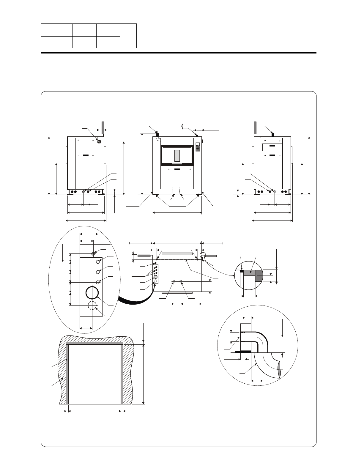
Washer extractor type 470 standard Diagram no. 07100085
0102 6
8
8.Technical
characteristics
Heating Gas Electric Steam Thermic fluid
Characteristics Ø cage --------------------------- 770 mm (30.31")--------------------
Cage length ----------------------------- 1040 mm (41") ------------------Cage volume ----------------------- 467 dm³ (467 l) -------------------Specific load 1/11 --------------------------- 42.5 kg (94 lb)----------------------(dry linen, ISO 9398-4)
Opening cage doors (L x H) ---------------- 2x450 x 400 mm (17.71x15.74")----------Opening drum door (L x H) ------------------ 935 x 527 mm (36.81x20.74") ------------
Floor area ------------------------ 1.52 m² (16.36 sq. ft) ----------------
Net weight --------------------------- 870 daN (1919 lb)-----------------
Weight loaded (high level) --------------------------- 1272 daN (2805 lb)----------------
Water, washing, low level xx l xx l xx l xx l
Water, washing, high level xx l xx l xx l xx l
Dynamic stress --------------------- F = 275 daN (606 lb)-------------------
Transmitted floor load ----------------------- 830 daN (1830 lb)--------------------
Spin efficiency ---------------------------------- 350 G ------------------------
Max. unbalance --------------------------- 5.5 kg (12.13 lb)--------------------
(L) Main switch to connect main cable
(M) Electric cable (section) 4x2.5 mm² 4x25 mm² 4x2.5 mm² 4x2.5 mm²
(N) or (N') Stuffing box for main cable
Supply voltage -------------------------380 / 415 V 3+E ~ 50/60 Hz------------
Installed electric power 5.8 kW 42 kW 5.8 kW 5.8 kW
Installed heating power 40 kW 36 kW - -
Electrical consumption for a normal cycle* 1.5 kWh/h 11 kWh/h 1.2 kWh/h 1.2 kWh/h
Heat loss -------------------3 % of installed heating power--------------
(G) Steam inlet DN 20 (3/4" BSP)
- Maximum supply pressure 600 kPa (87 psi)
- Steam instantaneous flow rate at 600 kPa x kg/h
- Steam consumption for a normal cycle* 24.5 kg/h at 600 kPa (87 psi)
(D) Hot water connection / flow DN 20 (3/4" BSP) - 70 l/min at 250 kPA (36 psi)
(E) Cold hard water connection / flow DN 20 (3/4" BSP) - 70 l/min at 250 kPA (36 psi)
(F) Cold soft water connection / flow (option) DN 20 (3/4" BSP) - 70 l/min at 250 kPA (36 psi)
Water supply minimum pressure --------------------------- 50 kPa (7.25 psi)------------------
Water supply maximum pressure --------------------------- 300 kPa (43.5 psi)----------------
Water consumption for a normal cycle* 638 l 610 l 610 l 610 l
Water consumption for an ECO cycle** 558 l 530 l 530 l 530 l
(K) Liquid detergents inlet
(H1 or H3 or H5) Drain connection --------------------------- Ø 75 mm (3")----------------------
(H2 or H4 or H6) Double drain connection --------------------------- Ø 75 mm (3")----------------------
Maximum drain flow rate xx l/min xx l/min xx l/min xx l/min
(I) Waste water collector ------------------------ DN 150 mm (6" BSP)----------------
(3 cm/m (3 %) minimum slope)
(J) Air vent hole ------------------------ Ø 60 mm (2.36 ") ---------------------
(N') Thermic fluid inlet DN 15 (1/2" BSP)
(G) Thermic fluid return DN 15 (1/2" BSP)
- Maximum supply pressure xxx kPa
- Installed calorific power xxx kcal
- Average calorific consumption xxx kcal/h
- Inner volume thermic fluid xx l
Gas inlet DN 20 (3/4" BSP)
Combustion products evacuation Ø 125 mm (5")
* normal cycle : prewash 3 min at 35 °C, drain. 2 min, main wash 4 min at 65 °C, drain 2 min, rinse 2 min, extract. 2 min, rinse 2 min,
extract 2 min, rinse 2 min, extrac. 10 min (cold water supply at 15 °C).
** ECO cycle : normal cycle with rinse 5 l/kg instead of 6 l/kg dry linen.
Notice
Date Page
01201055
INSTRUCTION
HANDBOOK
0999 7
8
8.Technical
characteristics
07100087
Washer extractor type 670 standard
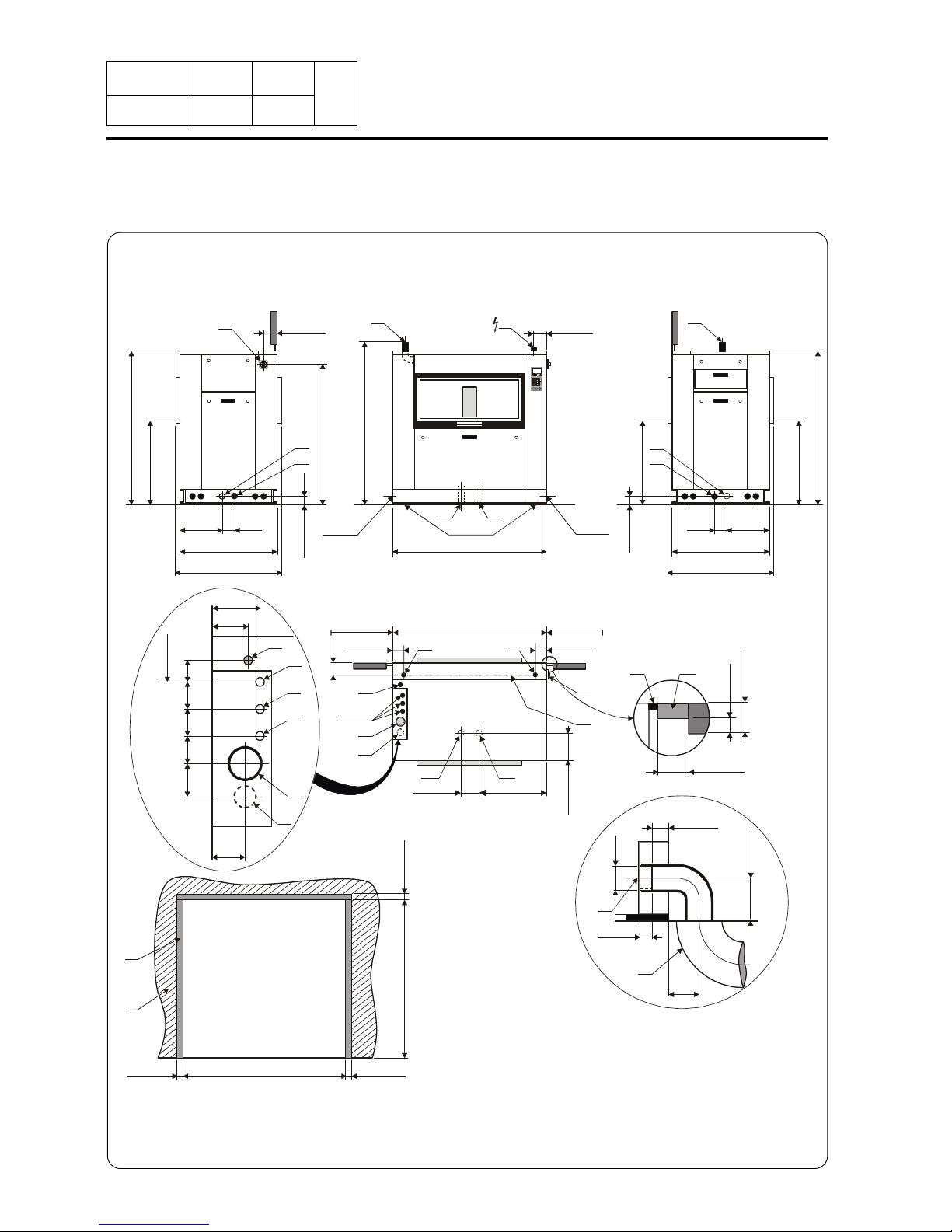
Front viewRight view Left view
Top view
Example of
drain connection
J
200078.74”
200078.74”
H1-H2 H6
H6
H5
H5
H3 H1
H4 H2
H3-H4
1
7
1
0
/
6
7
.
3
2
”
J
150/5.9”
N
915/36”
NN'
M
L
F-D-E
J
K
G
E
J
K
F
D
G
L
“Gripsol”
8
7
0
/
3
4
.
2
5
”
1
6
1
0
/
6
3
.
3
8
”
> 1 m/40”
> 1 m/40”
> 1 m/40”
> 1 m/40”
430/17”
110/
4.33”
1
0
0
/
3
.
9
3
”
160/6.3”
980/38.58”
1015/39.96”
1
4
4
0
/
5
6
.
6
9
”
8
7
0
/
3
4
.
2
5
”
1
6
1
0
/
6
3
.
3
8
”
430/17”
110/
4.33”
1
0
0
/
3
.
9
3
”
980/38.58”
1015/39.96”
55/2.16”
40/1.57”
1
0
0
/
3
.
9
3
”
Ø
7
5
/
3
”
H1
120/
4.72”
150/5.9”
150/5.9”
170/6.7”
2
7
5
/
1
0
.
8
”
1
3
0
/
5
.
1
”
2
7
0
/
1
0
.
6
”
100/
3.93”
1
0
0
/
3
.
9
3
”
8
0
/
3
.
1
5
”
8
0
/
3
.
1
5
”
8
0
/
3
.
1
5
”
135/5.3”
160/6.3”
7
5
/
3
”

Notice
Date Page
01201055
INSTRUCTION
HANDBOOK
0102 8
8
8.Technical
characteristics
Heating Gas Electric Steam Thermic fluid
Characteristics Ø cage --------------------------- 770 mm (30.31")--------------------
Cage length ----------------------------- 1500 mm (59") ------------------Cage volume ----------------------- 668 dm³ (668 l) -------------------Specific load 1/11 --------------------------- 61 kg (134 lb)----------------------(dry linen, ISO 9398-4)
Opening cage doors (L x H) ---------------- 2x600 x 400 mm (23.62x15.74")----------Opening drum door (L x H) --------------- 2x616 x 525 mm (24.25x20.66") -----------
Floor area ------------------------ 2 m² (21.53 sq. ft) --------------------
Net weight --------------------------- 940 daN (2073 lb)-----------------
Weight loaded (high level) ---------------------------1589 daN (3504 lb)-----------------
Water, washing, low level xx l xx l xx l xx l
Water, washing, high level xx l xx l xx l xx l
Dynamic stress --------------------- F = 466 daN (1028 lb)-------------------
Transmitted floor load ------------------------ 811 daN (1789 lb)------------------
Spin efficiency ---------------------------------- 350 G ------------------------
Max. unbalance --------------------------- 8 kg (17.65 lb)--------------------
(L) Main switch to connect main cable
(M) Electric cable (section) 4x2.5 mm² 4x35 mm² 4x2.5 mm² 4x2.5 mm²
(N) or (N') Stuffing box for main cable
Supply voltage -------------------------380 / 415 V 3+E ~ 50/60 Hz------------
Installed electric power 7.8 kW 61.5 kW 7.8 kW 7.8 kW
Installed heating power 40 kW 54 kW - -
Electrical consumption for a normal cycle* 2 kWh/h 23 kWh/h 2 kWh/h 2 kWh/h
Heat loss -------------------3 % of installed heating power--------------
(G) Steam inlet DN 20 (3/4" BSP)
- Maximum supply pressure 600 kPa (87 psi)
- Steam instantaneous flow rate at 600 kPa x kg/h
- Steam consumption for a normal cycle* 24.5 kg/h at 600 kPa (87 psi)
(D) Hot water connection / flow DN 20 (3/4" BSP) - 70 l/min at 250 kPA (36 psi)
(E) Cold hard water connection / flow DN 20 (3/4" BSP) - 70 l/min at 250 kPA (36 psi)
(F) Cold soft water connection / flow (option) DN 20 (3/4" BSP) - 70 l/min at 250 kPA (36 psi)
Water supply minimum pressure --------------------------- 50 kPa (7.25 psi)------------------
Water supply maximum pressure --------------------------- 300 kPa (43.5 psi)----------------
Water consumption for a normal cycle* 977 l 977 l 977 l 977 l
Water consumption for an ECO cycle** 782 l 782 l 782 l 782 l
(K) Liquid detergents inlet
(H1 or H3 or H5) Drain connection --------------------------- Ø 75 mm (3")----------------------
(H2 or H4 or H6) Double drain connection --------------------------- Ø 75 mm (3")----------------------
Maximum drain flow rate xx l/min xx l/min xx l/min xx l/min
(I) Waste water collector ------------------------ DN 150 mm (6" BSP)----------------
(3 cm/m (3 %) minimum slope)
(J) Air vent hole ------------------------ Ø 60 mm (2.36 ") ---------------------
(N') Thermic fluid inlet DN 15 (1/2" BSP)
(G) Thermic fluid return DN 15 (1/2" BSP)
- Maximum supply pressure xxx kPa
- Installed calorific power xxx kcal
- Average calorific consumption xxx kcal/h
- Inner volume thermic fluid xx l
Gas inlet DN 20 (3/4" BSP)
Combustion products evacuation Ø 125 mm (5")
Washer extractor type 670 standard Diagram no. 07100087
* normal cycle : prewash 3 min at 35 °C, drain. 2 min, main wash 4 min at 65 °C, drain 2 min, rinse 2 min, extract. 2 min, rinse 2 min,
extract 2 min, rinse 2 min, extrac. 10 min (cold water supply at 15 °C).
** ECO cycle : normal cycle with rinse 5 l/kg instead of 6 l/kg dry linen.

Notice
Date Page
01201055
INSTRUCTION
HANDBOOK
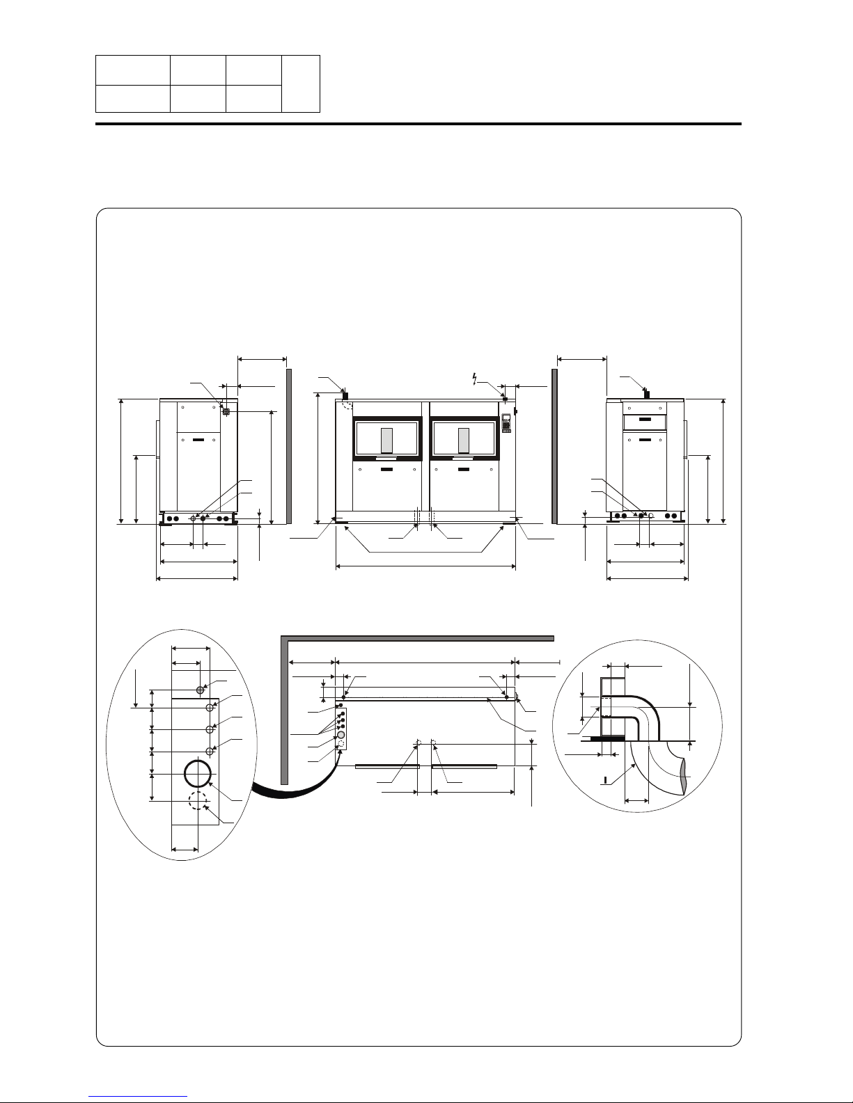
0999 9
8
07100082
Washer extractor type 230 barrier
Top view
Example of
drain connection
Front viewRight view Left view
8.Technical
characteristics
1
7
1
0
/
6
7
.
3
2
”
> 1 m/40”
55/2.16”
40/1.57”
1
0
0
/
3
.
9
3
”
Ø
7
5
/
3
”
150/5.9”
> 1 m/40”
1055/41.53”
1045/41.14”
1045/41.14”
N
JJ
F-D-E
J
K
E
J
K
F
D
G
G
H1-H2
H3-H4
NN'
M
L
H3 H1
H4 H2
H1
I
100/
3.93”
120/
4.72”
100/3.93”
5
0
/
1
.
9
7
”
1
0
0
/
3
.
9
3
”
R
P
O
P
100/3.93”
100/3.93”
1
0
0
/
3
.
9
3
”
1075/42.32”
1
6
2
5
/
6
3
.
9
7
”
L
H6 H5
170/6.7”
440/
17.3”
2
7
5
/
1
0
.
8
”
“Gripsol”
H6
H5
8
7
0
/
3
4
.
2
5
”
1
6
1
0
/
6
3
.
3
8
”
430/17”
110/
4.33”
1
0
0
/
3
.
9
3
”
160/6.3”
980/38.58”
1
4
4
0
/
5
6
.
6
9
”
1055/41.53”
8
7
0
/
3
4
.
2
5
”
8
7
0
/
3
4
.
2
5
”
1
6
1
0
/
6
3
.
3
8
”
430/17”
110/
4.33”
1
0
0
/
3
.
9
3
”
980/38.58”
2
7
0
/
1
0
.
6
”
1
0
0
/
3
.
9
3
”
8
0
/
3
.
1
5
”
8
0
/
3
.
1
5
”
8
0
/
3
.
1
5
”
135/5.3”
160/6.3”
7
5
/
3
”
150/5.9”
150/5.9”
1
3
0
/
5
.
1
”

Notice
Date Page
01201055
INSTRUCTION
HANDBOOK
Washer extractor type 230 barrier Diagram no. 07100082
0102 10
8
8.Technical
characteristics
Heating Gas Electric Steam Thermic fluid
Characteristics Ø cage --------------------- 770 mm (30.31") -------------------
Cage length --------------------- 520 mm (20.47") ------------------Cage volume ---------------------- 229 dm³ (229 l) --------------------Specific load 1/11 -------------------- 21 kg (46 lb) ------------------(dry linen, ISO 9398-4)
Opening cage doors (L x H) ----------- 450 x 400 mm (17.71x15.74") ------------Opening drum door (L x H) ----------- 466 x 525 mm (18.34x20.67") -------------
Floor area ------------------- 1 m² (10.76 sq. ft) -------------------
Net weight --------------------- 670 daN (1478 lb) -------------------
Weight loaded (high level) --------------------- 934 daN (1840 lb) -------------------
Water, washing, low level xx l xx l xx l xx l
Water, washing, high level xx l xx l xx l xx l
Dynamic stress ---------------------- F = 101 daN (222 lb) --------------------
Transmitted floor load ----------------------- 814 daN (1795 lb) ----------------------
Spin efficiency ------------------------------- 350 G -------------------------------
Max. unbalance ----------------------------- 3.6 kg (7.94 lb) ---------------------
(L) Main switch to connect main cable
(M) Electric cable (section) 4x2.5 mm² 4x6 mm² 4x2.5 mm² 4x2.5 mm²
(N) or (N') Stuffing box for main cable
Supply voltage -------------------------380 / 415 V 3+E ~ 50/60 Hz------------
Installed electric power 3.7 kW 21.70 kW 3.7 kW 3.7 kW
Installed heating power 40 kW 18 kW - -
Electrical consumption for a normal cycle* 0.8 kWh/h 5.3 kWh/h 0.6 kWh/h 0.6 kWh/h
Heat loss -------------------3 % of installed heating power--------------
(G) Steam inlet DN 20 (3/4" BSP) (87 psi)
- Maximum supply pressure 600 kPa
- Steam instantaneous flow rate at 600 kPa x kg/h
- Steam consumption for a a normal cycle* 12 kg/h at 600 kPa (87 psi)
(D) Hot water connection / flow DN 20 (3/4" BSP) - 70 l/min at 250 kPA (36 psi)
(E) Cold hard water connection / flow DN 20 (3/4" BSP) - 70 l/min at 250 kPA (36 psi)
(F) Cold soft water connection / flow (option) DN 20 (3/4" BSP) - 70 l/min at 250 kPA (36 psi)
Water supply minimum pressure ---------------------- 50 kPa (7.25 psi) -------------------
Water supply maximum pressure ---------------------- 300 kPa (43.5 psi) ------------------
Water consumption for a normal cycle* 360 l 340 l 340 l 340 l
Water consumption for an ECO cycle** 282 l 260 l 260 l 260 l
(K) Liquid detergents inlet
(H1 or H3 or H5) Drain connection ------------------------- Ø 75 mm (3") ---------------------
(H2 or H4 or H6) Double drain connection ------------------------- Ø 75 mm (3") ---------------------
Maximum drain flow rate xx l/min xx l/min xx l/min xx l/min
(I) Waste water collector --------------------- DN 150 mm (6" BSP) --------------
(3 cm/m (3 %) minimum slope)
(J) Air vent hole ------------------------ Ø 60 mm (2.36") ------------------
(N') Thermic fluid inlet
DN 15 (1/2" BSP)
(G) Thermic fluid return DN 15 (1/2" BSP)
- Maximum supply pressure xxx kPa
- Installed calorific power xxx kcal
- Average calorific consumption xxx kcal/h
- Inner volume thermic fluid xx l
Gas inlet DN 20 (3/4" BSP)
Combustion products evacuation Ø 125 mm (5")
(O) Barrier partition (provided by customer)
(P) Frame 50x100 mm (provided by customer)
(R) Foam joint
* normal cycle : prewash 3 min at 35 °C, drain. 2 min, main wash 4 min at 65 °C, drain 2 min, rinse 2 min, extract. 2 min, rinse 2 min,
extract 2 min, rinse 2 min, extrac. 10 min (cold water supply at 15 °C).
** ECO cycle : normal cycle with rinse 5 l/kg instead of 6 l/kg dry linen.
Notice
Date Page
01201055
INSTRUCTION
HANDBOOK
0999 11
8
07100084
Washer extractor type 340 barrier
Top view
Example of
drain connection
Front viewRight view Left view
8.Technical
characteristics
> 1 m/40”
> 1 m/40”
1285/50.59”
1285/50.59”
H1-H2
H3-H4
N
M
H3 H1
H4 H2
R
P
O
P
1315/51.77”
F-D-E
J
K
G
1
7
1
0
/
6
7
.
3
2
”
J J
150/5.9”
N
H1
I
N'
E
J
K
F
D
G
L
L
H6 H5
560/22”
2
7
5
/
1
0
.
8
”
“Gripsol”
H6
H5
1055/41.53”
8
7
0
/
3
4
.
2
5
”
1
6
1
0
/
6
3
.
3
8
”
430/17”
110/
4.33”
1
0
0
/
3
.
9
3
”
160/6.3”
980/38.58”
1
4
4
0
/
5
6
.
6
9
”
100/
3.93”
100/3.93” 100/3.93”
1
0
0
/
3
.
9
3
”
1
6
2
5
/
6
3
.
9
7
”
2
7
0
/
1
0
.
6
”
1
0
0
/
3
.
9
3
”
8
0
/
3
.
1
5
”
8
0
/
3
.
1
5
”
8
0
/
3
.
1
5
”
135/5.3”
160/6.3”
7
5
/
3
”
1
3
0
/
5
.
1
”
55/2.16”
40/1.57”
1
0
0
/
3
.
9
3
”
Ø
7
5
/
3
”
120/
4.72”
100/3.93”
5
0
/
1
.
9
7
”
1
0
0
/
3
.
9
3
”
1055/41.53”
8
7
0
/
3
4
.
2
5
”
8
7
0
/
3
4
.
2
5
”
1
6
1
0
/
6
3
.
3
8
”
430/17”
110/
4.33”
1
0
0
/
3
.
9
3
”
980/38.58”
170/6.7”
150/5.9”
150/5.9”

Notice
Date Page
01201055
INSTRUCTION
HANDBOOK
Washer extractor type 340 barrier Diagram no. 07100084
0102 12
8
8.Technical
characteristics
Heating Gas Electric Steam Thermic fluid
Characteristics Ø cage --------------------- 770 mm (30.31") -------------------
Cage lenght ----------------------- 760 mm (30") ------------------Cage volume ---------------------- 338 dm³ (338 l) --------------------Specific load 1/11 ------------------------ 31 kg (68 lb) ---------------------(dry linen, ISO 9398-4)
Opening cage doors (L x H) -------------- 600 x 400 mm (23.62x15.74") ------------Opening drum door (L x H) --------------- 616 x 525 mm (24.25x20.67") -------------
Floor area ------------------ 1.25 m² (13.45 sq. ft) ------------------
Net weight --------------------- 760 daN (1676 lb) -------------------
Weight loaded (high level) -------------------- 1008 daN (2223 lb) ------------------
Water, washing, low level xx l xx l xx l xx l
Water, washing, high level xx l xx l xx l xx l
Dynamic stress -------------------- F = 155 daN (342 lb) ----------------
Transmitted floor load ---------------------- 800 daN (1765 lb) ------------------
Spin efficiency ----------------------------- 350 G ---------------------------
Max. unbalance ------------------------ 4.8 kg (10.58 lb) ------------------
(L) Main switch to connect main cable
(M) Electric cable (section) 4x2.5 mm² 4x16 mm² 4x2.5 mm² 4x2.5 mm²
(N) or (N') Stuffing box for main cable
Supply voltage -------------------------380 / 415 V 3+E ~ 50/60 Hz------------
Installed electric power 4.8 kW 32 kW 4.8 kW 4.8 kW
Installed heating power 40 kW 27 kW - -
Electrical consumption for a normal cycle* 1.2 kWh/h 9.2 kWh/h 1 kWh/h 1 kWh/h
Heat loss -------------------3 % of installed heating power--------------
(G) Steam inlet DN 20 (3/4" BSP) (87 psi)
- Maximum supply pressure 600 kPa
- Steam instantaneous flow rate at 600 kPa x kg/h
- Steam consumption for a normal cycle* 18 kg/h at 600 kPa (87 psi)
(D) Hot water connection / flow DN 20 (3/4" BSP) - 70 l/min at 250 kPA (36 psi)
(E) Cold hard water connection / flow DN 20 (3/4" BSP) - 70 l/min at 250 kPA (36 psi)
(F) Cold soft water connection / flow (option) DN 20 (3/4" BSP) - 70 l/min at 250 kPA (36 psi)
Water supply minimum pressure ---------------------- 50 kPa (7.25 psi) -------------------
Water supply maximum pressure --------------------- 300 kPa (43.5 psi) ------------------
Water consumption for a normal cycle* 495 l 470 l 470 l 470 l
Water consumption for an ECO cycle** 315 l 395 l 395 l 395 l
(K) Liquid detergents inlet
(H1 or H3 or H5) Drain connection ------------------------- Ø 75 mm (3") ---------------------
(H2 or H4 or H6) Double drain connection ------------------------- Ø 75 mm (3") ---------------------
Maximum drain flow rate xx l/min xx l/min xx l/min xx l/min
(I) Waste water collector --------------------- DN 150 mm (6" BSP) --------------
(3 cm/m (3 %) minimum slope)
(J) Air vent hole ------------------------ Ø 60 mm (2.36") ------------------
(N') Thermic fluid inlet DN 15 (1/2" BSP)
(G) Thermic fluid return DN 15 (1/2" BSP)
- Maximum supply pressure xxx kPa
- Installed calorific power xxx kcal
- Average calorific consumption xxx kcal/h
- Inner volume thermic fluid xx l
Gas inlet DN 20 (3/4" BSP)
Combustion products evacuation Ø 125 mm (5")
(O) Barrier partition (provided by customer)
(P) Frame 50x100 mm (provided by customer)
(R) Foam joint
* normal cycle : prewash 3 min at 35 °C, drain. 2 min, main wash 4 min at 65 °C, drain 2 min, rinse 2 min, extract. 2 min, rinse 2 min,
extract 2 min, rinse 2 min, extrac. 10 min (cold water supply at 15 °C).
** ECO cycle : normal cycle with rinse 5 l/kg instead of 6 l/kg dry linen.
Notice
Date Page
01201055
INSTRUCTION
HANDBOOK
0999 13
8
07100086
Washer extractor type 470 barrier
Top view
Example of
drain connection
Front viewRight view Left view
8.Technical
characteristics
1565/61.61”
1565/61.61”
H1-H2
H3-H4
N
H3 H1
H4 H2
O
P
1595/62.79”
F-D-E
J
K
G
1
7
1
0
/
6
7
.
3
2
”
J
J
150/5.9”
N
N'
E
J
K
F
D
G
L
M
L
“Gripsol”
H6
H5
H6 H5
700/27.56”
1055/41.53”
8
7
0
/
3
4
.
2
5
”
1
6
1
0
/
6
3
.
3
8
”
430/17”
110/
4.33”
1
0
0
/
3
.
9
3
”
160/6.3”
980/38.58”
1
4
4
0
/
5
6
.
6
9
”
100/
3.93”
100/3.93”
100/3.93”
1
0
0
/
3
.
9
3
”
1
6
2
5
/
6
3
.
9
7
”
2
7
0
/
1
0
.
6
”
1
0
0
/
3
.
9
3
”
8
0
/
3
.
1
5
”
8
0
/
3
.
1
5
”
8
0
/
3
.
1
5
”
135/5.3”
160/6.3”
7
5
/
3
”
1
3
0
/
5
.
1
”
55/2.16”
40/1.57”
1
0
0
/
3
.
9
3
”
Ø
7
5
/
3
”
H1
I
120/
4.72”
100/3.93”
5
0
/
1
.
9
7
”
1
0
0
/
3
.
9
3
”
R
P
1055/41.53”
8
7
0
/
3
4
.
2
5
”
8
7
0
/
3
4
.
2
5
”
1
6
1
0
/
6
3
.
3
8
”
430/17”
110/
4.33”
1
0
0
/
3
.
9
3
”
980/38.58”
> 1 m/40”
> 1 m/40”
170/6.7”
2
7
5
/
1
0
.
8
”
150/5.9”
150/5.9”

Notice
Date Page
01201055
INSTRUCTION
HANDBOOK
Washer extractor type 470 barrier Diagram no. 07100086
0102 14
8
8. Characteristics
techniques
Heating Gas Electric Steam Thermic fluid
Characteristics Ø cage --------------------- 770 mm (30.31") -------------------
Cage length ----------------------- 1040 mm (41") ------------------Cage volume ---------------------- 467 dm³ (467 l) --------------------Specific load 1/11 ----------------------- 42.5 kg (94 lb) --------------------(dry linen, ISO 9398-4)
Opening cage doors (L x H) -------------- 2x450 x 400 mm (17.71x15.74") ------------Opening drum door (L x H) ----------------- 935 x 527 mm (36.81x20.74") -------------
Floor area ------------------ 1.52 m² (16.36 sq. ft) ------------------
Net weight -------------------- 870 daN (1919 lb) -------------------
Weight loaded (high level) -------------------- 1272 daN (2805 lb) ------------------
Water, washing, low level xx l xx l xx l xx l
Water, washing, high level xx l xx l xx l xx l
Dynamic stress -------------------- F = 275 daN (606 lb) ----------------
Transmitted floor load ---------------------- 830 daN (1830 lb) ------------------
Spin efficiency ----------------------------- 350 G ---------------------------
Max. unbalance ------------------------ 5.5 kg (12.13 lb) ------------------
(L) Main switch to connect main cable
(M) Electric cable (section) 4x2.5 mm² 4x25 mm² 4x2.5 mm² 4x2.5 mm²
(N) or (N') Stuffing box for main cable
Supply voltage -------------------------380 / 415 V 3+E ~ 50/60 Hz------------
Installed electric power 5.8 kW 42 kW 5.8 kW 5.8 kW
Installed heating power 40 kW 36 kW - -
Electrical consumption for a normal cycle* 1.5 kWh/h 11 kWh/h 1.2 kWh/h 1.2 kWh/h
Heat loss -------------------3 % of installed heating power--------------
(G) Steam inlet DN 20 (3/4" BSP)
- Maximum supply pressure 600 kPa (87 psi)
- Steam instantaneous flow rate at 600 kPa x kg/h
- Steam consumption for a normal cycle* 24.5 kg/h at 600 kPa (87 psi)
(D) Hot water connection / flow DN 20 (3/4" BSP) - 70 l/min at 250 kPA (36 psi)
(E) Cold hard water connection / flow DN 20 (3/4" BSP) - 70 l/min at 250 kPA (36 psi)
(F) Cold soft water connection / flow (option) DN 20 (3/4" BSP) - 70 l/min at 250 kPA (36 psi)
Water supply minimum pressure ---------------------- 50 kPa (7.25 psi) -------------------
Water supply maximum pressure --------------------- 300 kPa (43.5 psi) ------------------
Water consumption for a normal cycle* 638 l 610 l 610 l 610 l
Water consumption for an ECO cycle** 558 l 530 l 530 l 530 l
(K) Liquid detergents inlet
(H1 or H3 or H5) Drain connection ------------------------- Ø 75 mm (3") ---------------------
(H2 or H4 or H6) Double drain connection ------------------------- Ø 75 mm (3") ---------------------
Maximum drain flow rate xx l/min xx l/min xx l/min xx l/min
(I) Waste water collector --------------------- DN 150 mm (6" BSP) --------------
(3 cm/m (3 %) minimum slope)
(J) Air vent hole ------------------------ Ø 60 mm (2.36") ------------------
(N') Thermic fluid inlet DN 15 (1/2" BSP)
(G) Thermic fluid return DN 15 (1/2" BSP)
- Maximum supply pressure xxx kPa
- Installed calorific power xxx kcal
- Average calorific consumption xxx kcal/h
- Inner volume thermic fluid xx l
Gas inlet DN 20 (3/4" BSP)
Combustion products evacuation Ø 125 mm (5")
(O) Barrier partition (provided by customer)
(P) Frame 50x100 mm (provided by customer)
(R) Foam joint
* normal cycle : prewash 3 min at 35 °C, drain. 2 min, main wash 4 min at 65 °C, drain 2 min, rinse 2 min, extract. 2 min, rinse 2 min,
extract 2 min, rinse 2 min, extrac. 10 min (cold water supply at 15 °C).
** ECO cycle : normal cycle with rinse 5 l/kg instead of 6 l/kg dry linen.
 Loading...