

WARNING: ALL OPERATING AND MAINTENANCE PROCEDURES SHOWN ON THE NEXT
PAGE OF THIS MANUAL MUST BE FOLLOWED DAILY FOR PROPER OPERATION OF
YOUR WASCOMAT MACHINE.
PLEASE ENTER THE FOLLOWING INFORMATION AS IT APPEARS ON THE MACHINE(S)
DATA PLATE(S).
MAKE CERTAIN TO KEEP THIS MANUAL IN A SECURE PLACE FOR FUTURE
REFERENCE.
MACHINE TYPE OR MODEL
MACHINE SERIAL NUMBER(S)
ELECTRICAL CHARACTERISTICS:________ VOLTS, _______ PHASE,_______ HZ.
OPERATING & MAINTENANCE MANUAL
WASCOMAT SELECTA
S28/125
S28/185
471 1562-69/03
00.23

WARNING: ALL OPERATING AND MAINTENANCE PROCEDURES SHOWN ON THE NEXT
PAGE OF THIS MANUAL MUST BE FOLLOWED DAILY FOR PROPER OPERATION OF
YOUR WASCOMAT MACHINE.
PLEASE ENTER THE FOLLOWING INFORMATION AS IT APPEARS ON THE MACHINE(S)
DATA PLATE(S).
MAKE CERTAIN TO KEEP THIS MANUAL IN A SECURE PLACE FOR FUTURE
REFERENCE.
MACHINE TYPE OR MODEL
MACHINE SERIAL NUMBER(S)
ELECTRICAL CHARACTERISTICS:________ VOLTS, _______ PHASE,_______ HZ.
OPERATING & MAINTENANCE MANUAL
WASCOMAT SELECTA
S28/125
S28/185

SAFETY AND WARNINGS SIGNS
Replace If Missing Or Illegible
One or more of these signs must be affixed on each machine as indicated, when not included as part of the front instruction panel.
LOCATED ON THE OPERATING INSTRUCTION SIGN OF THE MACHINE:
LOCATED AT THE REAR OF THE MACHINE:
INSTALLATION AND MAINTENANCE WARNINGS
1. This machine MUST be securely bolted according to the installation instruction to
reduce the risk of fire and to prevent serious injury, or damage to the machine.
Pour reduire les risques d'incendie, fixer cet appareil sur un plancher beton sans
revetement.
2. If installed on a floor of combustible material, the floor area below this machine must
be covered by a metal sheet extending to the outer edges of the machine.
3. This machine MUST be connected to a dedicated electrical circuit to which no other
lightning unit or general purpose receptacle is connected. Use copper conductor only.
Utiliser seulement des conducteurs en cuivre.
4. This machine MUST be serviced and operated in compliance with manufacturer's
instructions. CHECK DOOR LOCKS EVERY DAY FOR PROPER OPERATION TO PREVENT INJURY OR DAMAGE. IF THE DOOR LOCK FAILS TO OPERATE PROPERLY,
PLACE THE MACHINE OUT OF ORDER UNTIL THE PROBLEM IS CORRECTED.
5. Disconnect power prior to servicing of machine.
Deconnecter cet appareil del'alimentation avant de proceder a l'entretien.
6. To remove top panel, first remove screws at the rear. When remounting the top,
reinstall them. To remove the top panel on models on which it is secured by one or
two keylocks, use the keys originally shipped in the drum package. Be certain to
relock after remounting the top panel.
MANUFACTURED BY WASCATOR
DISTRIBUTED BY WASCOMAT INWOOD, NEW YORK, USA
LOCATED ON THE DOOR:
DO NOT ATTEMPT TO OPEN DOOR
UNTIL PROGRAM HAS FINISHED AND
DRUM HAS STOPPED ROTATING.
WARNING !
If you need to order more safety or warning
signs, call Wascomat's parts department at
516-371-2000, or call your local dealer.
471 7651-17
CAUTION
1. Do not open washer door until cycle is completed, operating
light is off, and wash cylinder has stopped rotating.
2. Do not tamper with the door safety switch or door lock.
3. Do not attempt to open door or place hands into washer to
remove or add clothes during operation. This can cause
serious injury.
MACHINE SHOULD NOT BE USED BY CHILDREN
PRECAUCION
1. No abra la puerta de la máquina lavadora sino hasta que la
máquina haya terminado su ciclo, la luz operativa esté apaga
da y el cilindro de lavado haya completamento terminado de
girar.
2. No interferia o manipule el switch o la cerradura de la puerta.
3. No trate de abrir la puerta o meta las manos dentro de la
máquina para meter o sacar ropa mientras la máquina está
en operación, pues puede resultar seriamento herido.
LAS MÁQUINAS NO DEBEN SER USADAS POR NIÑOS
471 7662-02

NOTICE TO: OWNERS, OPERATORS AND DEALERS OF WASCOMAT MACHINES
II
IMPROPER INSTALLATION AND INADEQUATE MAINTENANCE, POOR HOUSEKEEPING AND WILLFUL
NEGLECT OR BYPASSING OF SAFETY DEVICES MAY RESULT IN SERIOUS ACCIDENTS OR INJURY.
TO ASSURE THE SAFETY OF CUSTOMERS AND/OR OPERATORS OF YOUR MACHINE, THE FOLLOWING MAINTENANCE CHECKS MUST BE PERFORMED ON A DAILY BASIS.
1. Prior to operation of the machine, check to make certain that all operating instructions and
warning signs are affixed to the machine and legible. (See the following page of this manual
for description and location of the signs.) Missing or illegible ones must be replaced immediately. Be sure you have spare signs and labels available at all times. These can be obtained from your dealer or Wascomat.
2. Check the door safety interlock, as follows:
(a) OPEN THE DOOR of the machine and attempt to start in the normal manner:
For SELECTA 28 models, select a wash program and press the Start button.
THE MACHINE(S) MUST NOT START !
(b) CLOSE THE DOOR to start machine operation and, while it is operating, attempt to
open the door without exerting extreme force on the door handle. The door should
remain locked!
If the machine can start with the door open, or can continue to operate with the door
unlocked, the door interlock is no longer operating properly. The machine must be
placed out of order and the interlock immediately replaced.
(See the door interlock section of the manual.)
3. DO NOT UNDER ANY CIRCUMSTANCES ATTEMPT TO BYPASS OR REWIRE ANY OF
THE MACHINE SAFETY DEVICES AS THIS CAN RESULT IN SERIOUS ACCIDENTS.
4. Be sure to keep the machine(s) in proper working order: Follow all maintenance and
safety procedures. Further information regarding machine safety, service and parts can be
obtained from your dealer or from Wascomat through its Teletech Service Hotline 516/371-0700.
All requests for assistance must include the model, serial number and electrical characteristics as
they appear on the machine identification plate. Insert this information in the space provided on the
previous page of this manual.
5. WARNING: DO NOT OPERATE MACHINE(S) WITH SAFETY DEVICES BYPASSED, REWIRED OR
INOPERATIVE! DO NOT OPEN MACHINE DOOR UNTIL DRUM HAS STOPPED ROTATING!


Wascomat Selecta S28/125 • S28/185
Contents
Introduction ...................................................................... 1
Technical data..................................................................2
Installation ........................................................................ 5
Safety rules ....................................................................14
Operating instructions ....................................................15
Mechanical and electrical design ...................................19
Maintenance...................................................................36
Trouble-shooting ............................................................37
Safety instructions
• The machine is designed for water washing only.
• The machine must not be used by children.
• All installation operations are to be carried out by qualified
personnel. Licensed personnel are necessary for all electric
power wiring.
• The interlock of the door must be checked daily for proper
operation and must not be bypased.
• All seepage in the system, due to faulty gaskets etc., must be
repaired immediately.
• All service personnel must be fully familiar with the operating
manual before attempting any repair or maintenance of the
machine.
• The machine must not be sprayed with water, otherwise short
circuiting may occur.
• Fabric softeners with volatile or inflammable fluids are not to
be used in the machine.
Consignes de sécurité
• La machine est conçue pour le lavage à l'eau exclusivement.
• La machine ne peut être utilisée par des enfants.
• Tous les travaux d'installation doivent être effectués par une
personne qualifiée. Tous les câblages électriques doivent être
réalisés par un électricien diplômé.
• Le verrouillage du hublot doit être vérifié chaque jour et ne
peut être neutralisé.
• Tout fuite du système, due à des joints défectueux etc., doit
être réparée sans délai.
• Tous les membres du personnel d'entretien doivent être
parfaitement familiarisés avec le manuel d'entretien avant
d'entreprendre une réparation ou un entretien de la machine.
• Ne jamais asperger d'eau la machine sous peine de risquer un
court-circuit.
• Ne pas utiliser dans la machine des adoucissants textiles
contenant des liquides volatils ou inflammables.
The manufacturer reserves the right to make changes to design and
material specifications, without notifications.
1
Introduction
Introduction
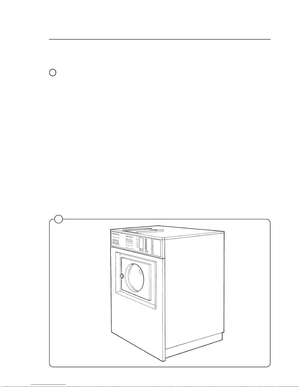
The Selecta 28 model washer/extractor has been developed to meet the
heavy duty requirements of hotels, motels, nursing homes, hospitals, professional laundries, restaurants, airlines, ships, schools, colleges and all
on-premises laundries where flexibility and quick formula variation, coupled
with high quality automatic washing, are required.
The Selecta offers 28 pre-set wash programs which can be selected by
means of push buttons. These programs are designed to suit a variety of
fabrics and offer different water temperatures, water levels, wash periods
and supply injection. The machine is designed for connection to hot and
cold water supplies and to be used with free-standing liquid supply injectors
which can be activated by signals from the machine.
All parts of the machine which come into contact with the items being
washed are made of heavy gauge surgical stainless steel, ensuring long life
and lasting beauty, as well as full protection for no-iron fabrics. All electrical
components are made accessible for servicing by simply removing the top
panel.
This manual contains a technical description of the machine and instructions for its installation, operation and maintenance. Together with the
wiring diagram which accompanies each individual machine it should be
kept in a safe place for easy reference.
When ordering spare parts or contacting the manufacturer for any purpose
always give the machine serial number, model, voltage and other electrical
characteristics appearing on the nameplate at the rear of the machine.
G135
1
Fig.
1

Technical data
Technical data Wascomat Selecta S28/125
Dry load capacity up to 35 lbs
Overall dimensions Width 745 mm 29 5/16 in
Depth (at the top) 915 mm 36 in
Height 1196 mm 47 4/6 in
Net weight 210 kg 462 lbs
Inner drum Diameter 620 mm 24 1/2 in
Depth 520 mm 20 1/2 in
Volume 157 litre 5.65 cu.ft
Speed Wash 52 r.p.m.
Extraction 500 r.p.m.
G-factor During wash 0.9
During extraction 87
Floor loading Dyn force 2.4±4.8 576±1152 lbs. force
Motor speed During wash 360 r.p.m.
During extraction 3450 r.p.m.
Rated power Motor, wash 3-phase 300 W
0.4 HP
Motor, extract. 3-phase 1300 W
1.8 HP
Motor, wash 1-phase 280 W
0.4 HP
Motor, extract. 1-phase 1300 W
Voltage requirements Choice:
208-240 V 1-phase 60 Hz or
208-240 V 3-Phase 60 Hz
1.8 HP
Overcurrent protection Three-phase 15 A
Single-phase 20 A
Water connections
Recommended water pressure 2-6 kp/cm
2
25-85 psi
Hose connection, water 20 mm 3/4"
Hose connection, drain 74 mm 3"
2

Technical data Wascomat Selecta S28/185
Dry load capacity up to 50 lbs
Overall dimensions Width 827 mm 32 9/16 in
Depth (at the top)960 mm 37 13/16 in
Height 1315 mm 51 3/4 in
Net weight 264 kg 582 lbs
Inner drum Diameter 700 mm 27 9/16 in
Depth 600 mm 23 5/8 in
Volume 230 litre 8.1 cu.ft
Speed of rotation Wash 45 r.p.m.
Extraction 455 r.p.m.
G-factor During wash 0.8
During extraction 81
Floor loading Dyn force 3.1±5.2 kN 744±1248 lbs. force
Motor speed During wash 360 r.p.m
During extraction 3480 r.p.m
Rated output power Motor, wash 3-phase 400 W
0.55 HP
Motor, extract. 3-phase 2000 W
2.7 HP
Motor, wash 1-phase 400 W
0.55 HP
Motor, extract. 1-phase 1800 W
2.4 HP
Voltage requirements Choice:
208-240 V 1-phase 60 Hz
or
208-240 V 3-Phase 60 Hz
Overcurrent protection Three-phase 15 A
Single-phase 20 A
Water connections
Recommended water pressure 2-6 kp/cm
2
25-85 psi
Hose connection, water 20 DN 3/4"
Hose connection, drain 74 mm 3"
Technical data
3
Technical data
4
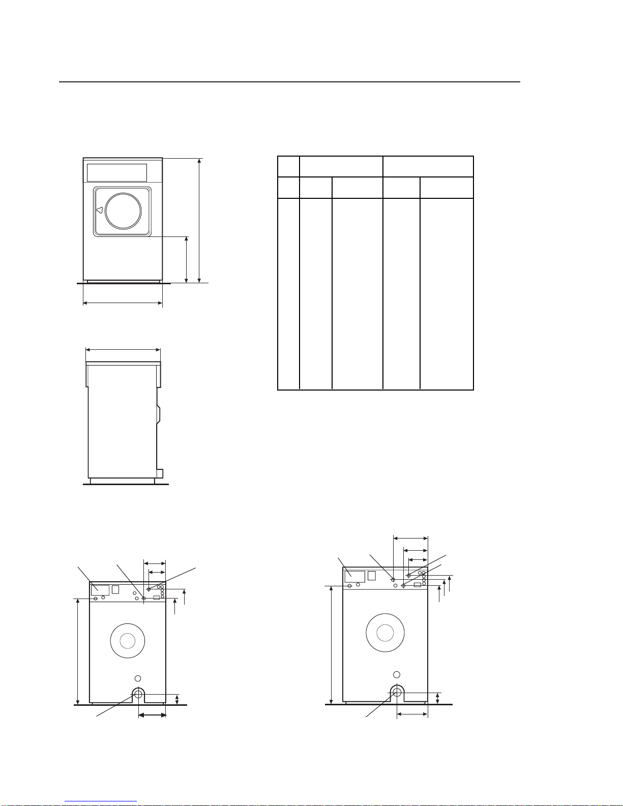
S28/125 S28/185
mm inches mm inches
A 1196 47 1/16 1315 51 3/4
B 465 18 5/16 540 21 1/4
C 745 29 5/16 829 32 9/16
D 915 36 960 37 13/16
E 205 8 1/16 205 8 1/16
F 160 6 5/16 160 6 5/16
G 1040 40 15/16 1160 45 5/8
H 1035 40 3/4 1155 45 1/2
J 100 3 15/16 100 3 15/16
K 270 10 5/8 260 10 1/4
L - - 295 11 9/16
M - - 1215 47 13/16
N 1135 44 11/16 1255 49 7/16
Outline and dimensions
S28/125 S28/185
1852b
1. Drain outlet
2. Electrical connections
3. Cold water inlet
4. Hot water inlet
A
B
C
D
2
4
3
1
K
J
H
N
E
F
G
K
1
J
G
H
M
N
L
E
F
2
4
3
4
SE125 SE185
mm inches mm inches
A 508 20 600 23 5/8
B 915 36 960 37 13/16
C 965 38 1010 39 3/4
D 115 4 1/2 115 4 1/2
E 600 23 5/8 700 27 9/16
F 815 32 1/16 900 35 9/16
G 786 30 15/16 922 36 1/8
H 991 39 1090 42 7/8
I 281 11 236 9 5/16
Installation
5
0271
1677
1132
B = machine outline to edge of front panel
C, F = minimum foundation pad for one machine
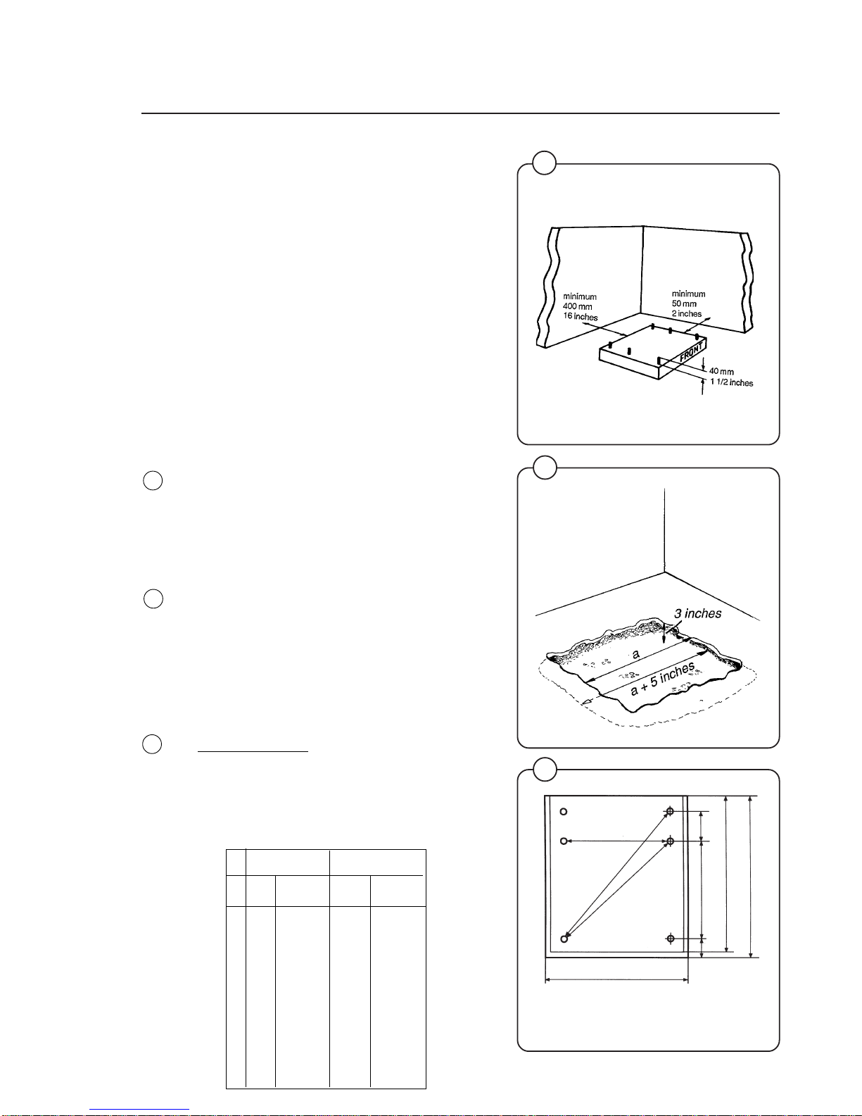
Installation
Machine foundation
The machines are designed to be bolted in
position to a concrete floor or specially prepared
concrete foundation. A template showing the size
of the foundation and positioning of the
foundation bolts can be provided by Wascomat.
For installation on an existing concrete floor, the
floor must be at least 8" thick and of good quality.
If the floor does not meet these requirements,
then a 6-8" high concrete foundation should be
made. A prefabricated steel base is available for
mounting of machines without an additional
foundation.
Follow the instructions below when making a
concrete foundation:
1. Decide where to place the machine and
consider maintenance requirements, i.e.
determine a suitable distance from the rear of
the foundation to the wall, and the distance
from the foundation to the nearest side wall.
The distance should be at least 16 and 12
inches, respectively.
2. Break up the floor to a depth of 3 inches,
making sure that the sides of the hole slope
inwards - the bottom of the hole should be 5
inches longer than the upper length.
3. Wet the hole well. Brush the bottom and sides
with cement grout.
4. Prepare a casing and fill with 3,000 PSI min.
concrete to form foundation. Make sure the
foundation is level.
5.
Use the template to position the foundation
bolts correctly - bolts are to extend 1 1/2"
above concrete.
NOTE: A prefabricated steel frame, designed
to be placed in the concrete instead of the
individual mounting bolts, is available.
2
3
4
Fig.
4
Fig.
3
Fig.
2
I
A
B
C
D
F
E
H
G
Installation
5
6
7
0274
0950
1133
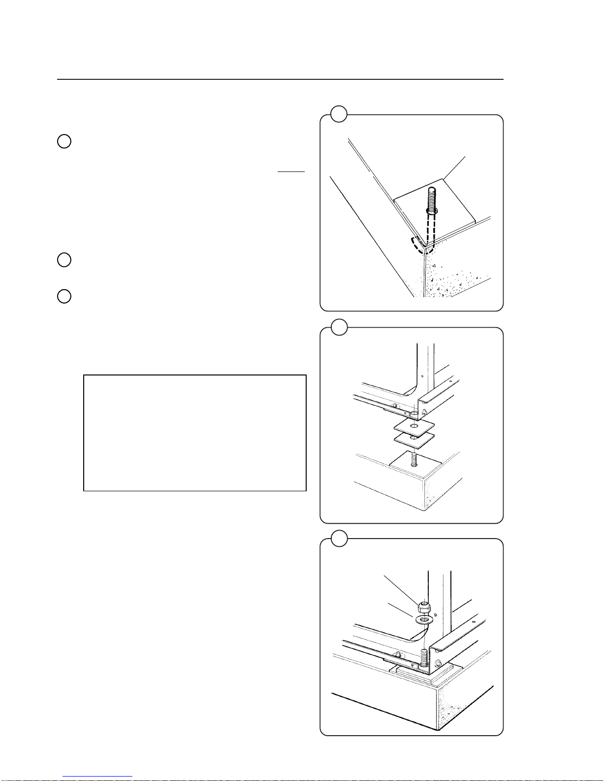
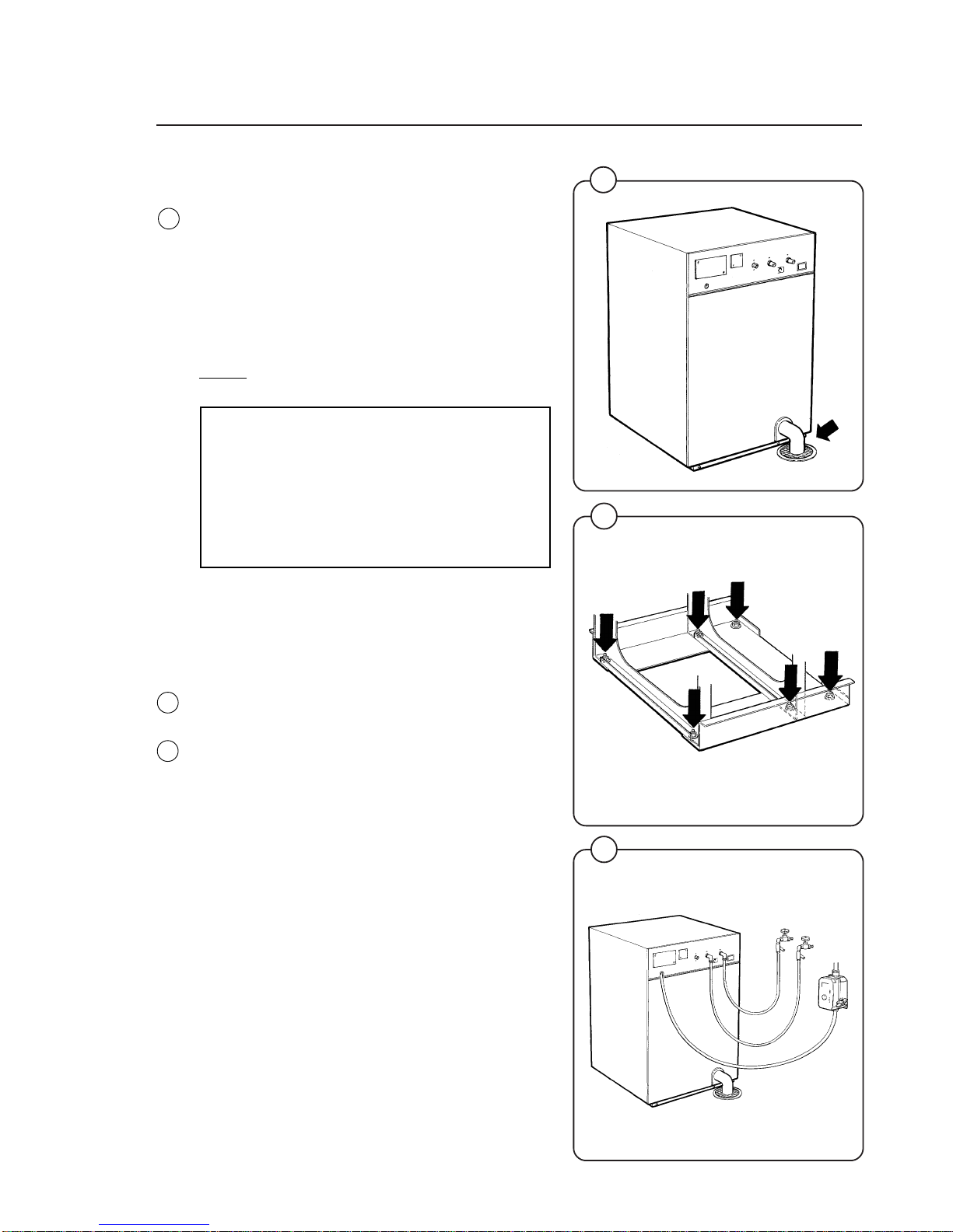
Mechanical installation
• Before mounting the machine place wide steel
shims on the concrete foundation over the
bolts.
• Lift the machine and lower it in position.
Never
use the door or the door handle to lift or lower
the machine since this can damage the door
and door interlock.
• Check that the machine is level front-to-rear
and side-to-side and standing firmly on the six
supporting points. Spacing washers must be
mounted if one or more of these points is not
resting against the floor/foundation.
• Place flat washers over the foundation bolts
and secure the machine in position by tightening the self-locking nuts. See illustration 7
below.
• Check and tighten the nuts every week for the
first month to compensate for any setting of
the foundation.
NOTE
If the side panels of the washer vibrate
during extraction remove the shipping
security which connects the top of the
cylinder to the upper section of the back
panel. This is used to prevent shipping
damage but has no function after the
machine is installed.
Fig.
5
6
steel
shim
selflocking
nut
flat washer
Fig.
6
Fig.
7
Installation
10
1830
1838
1839
1137
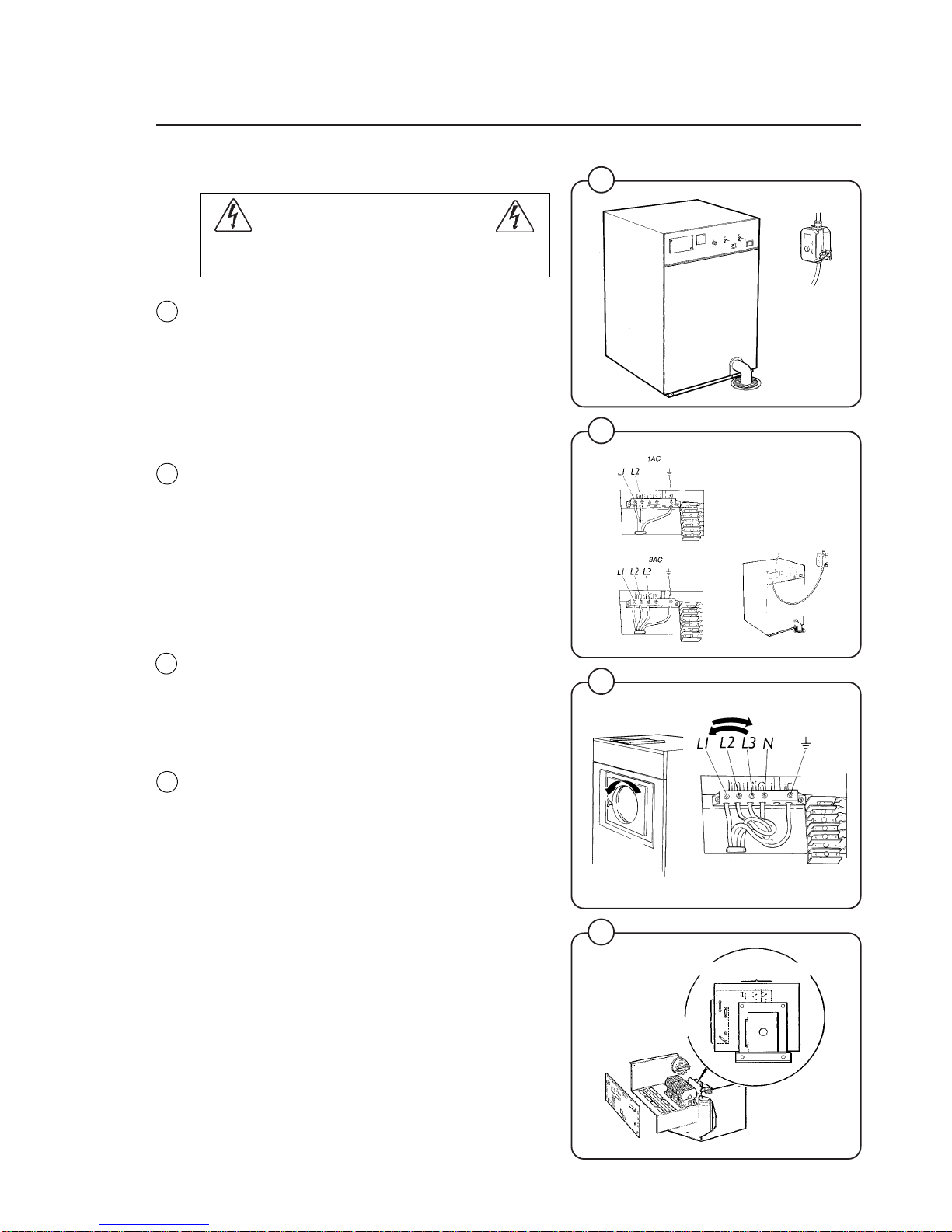
Electrical installation
All electrical installations are to be carried
out by licensed personnel.
Although the machines are fitted with a thermal
overload in the motor windings a separate threephase common-trip circuit breaker must be
installed for all three-phase machines.
For proper overcurrent protection, check the data
plate at the rear of the machine. Also consult
local electrical code for special requirements.
Use inverse-time circuit breaker only.
Connect L1, L2, L3 and ground wires according
to the markings of the terminal block. The cable
is to hang in a large loose loop, supported by the
clip of the terminal block.
After installation, do the following for 3-phase
machines:
Check the incoming power for a high voltage or
"stinger" leg. If present, connect that line to L2 on
the terminal block.
Start the machine and check that the drum
rotates in the proper direction during extraction,
i.e. counter-clockwise when seen from the front.
If the drum rotates in the wrong direction intercharge line L1 and L3 at the power connection
terminal.
Check that the jumper clips on the transformer on
the control unit are correctly connected in relation
to the incoming voltage. The different alternatives
are printed on the transformer circuit board.
8
9
7
11
jumper clip alternatives
strapping
area
Fig.
8
Fig.
9
Fig.
10
Fig.
11
Installation
14
12
13
1832
1870
1844
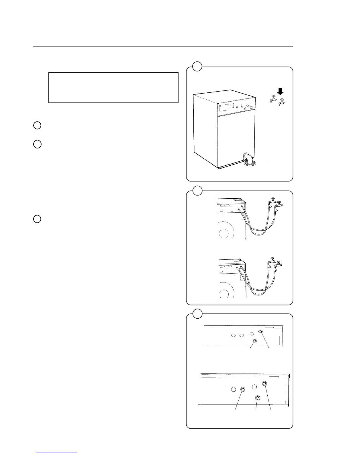
Water connection
NOTE
All plumbing must conform to national
and local plumbing codes.
Incoming water lines do not require non-return or
back-suction valves, as the machine is already
fitted with a siphon breaker. However, all incoming lines must be fitted with shut-off valves.
• Water inlets are labelled for hot and cold
water connection.
• Before connecting the water hoses flush the
water system thoroughly and check that the
filter at the machine inlet is fitted correctly.
This is essential since dirt and grit in the water
lines may clog the inlet valve filter screens
and/or the drain pilot valve. This could cause
the machine to fill very slowly or the drain
valve not operate properly.
• Connect the machine to the water mains with
3/4" reinforced rubber hosing not to exceed 6
ft in length. Hang the hosing in a large loop.
Do not use rigid piping.
Never force a hose onto the threads or you may
cause cross-threading and leaks. If this occurs,
place the threaded portion of the hose over the
valve threads and push forward firmly, to catch
the next thread. Then tighten.
Fig.
12
Fig.
14
Fig.
13
8
S28/125
S28/185
1846
S28/125
S28/185
hot water cold water
hot water cold water hot water
(to detergent supply box)
Installation
9
15
1833
16
1140
17
1834
Drain connection
Connect a 3" (75 mm) flexible hose to the drain
outlet of the machine.
The drain hose must not have sharp bends and
must slope from the machine to assure proper
drainage.
If the machine drains into an open trough, the
trough should have a minimum slope of 1/8-inch
to 1/4-inch per foot towards the main drain.
Do not reduce the size of the drain connection
from the machine to the waste line.
NOTE
To simplify installation, Wascomat has
made available the following hose kits:
For S28/125 – part. No. 002008
For S28/185 – part. No. 002009
These kits contain inlet hoses, drain hose,
hose clamps and washers.
Start-up and safety checklist
Before initial start-up of a Wascomat washerextractor, the following safety checks must be
performed:
• Make sure the machine is properly bolted to
the floor.
• Make sure that all electrical and plumbing
connections have been made in accordance
with applicable local codes.
• Use only flexible water fill and drain hoses of
the proper length to avoid sags and kinks.
• Make sure the machine is properly grounded
electrically.
Fig.
16
Fig.
17
Fig.
15
Installation
10
1
2
19
3648
18
3649
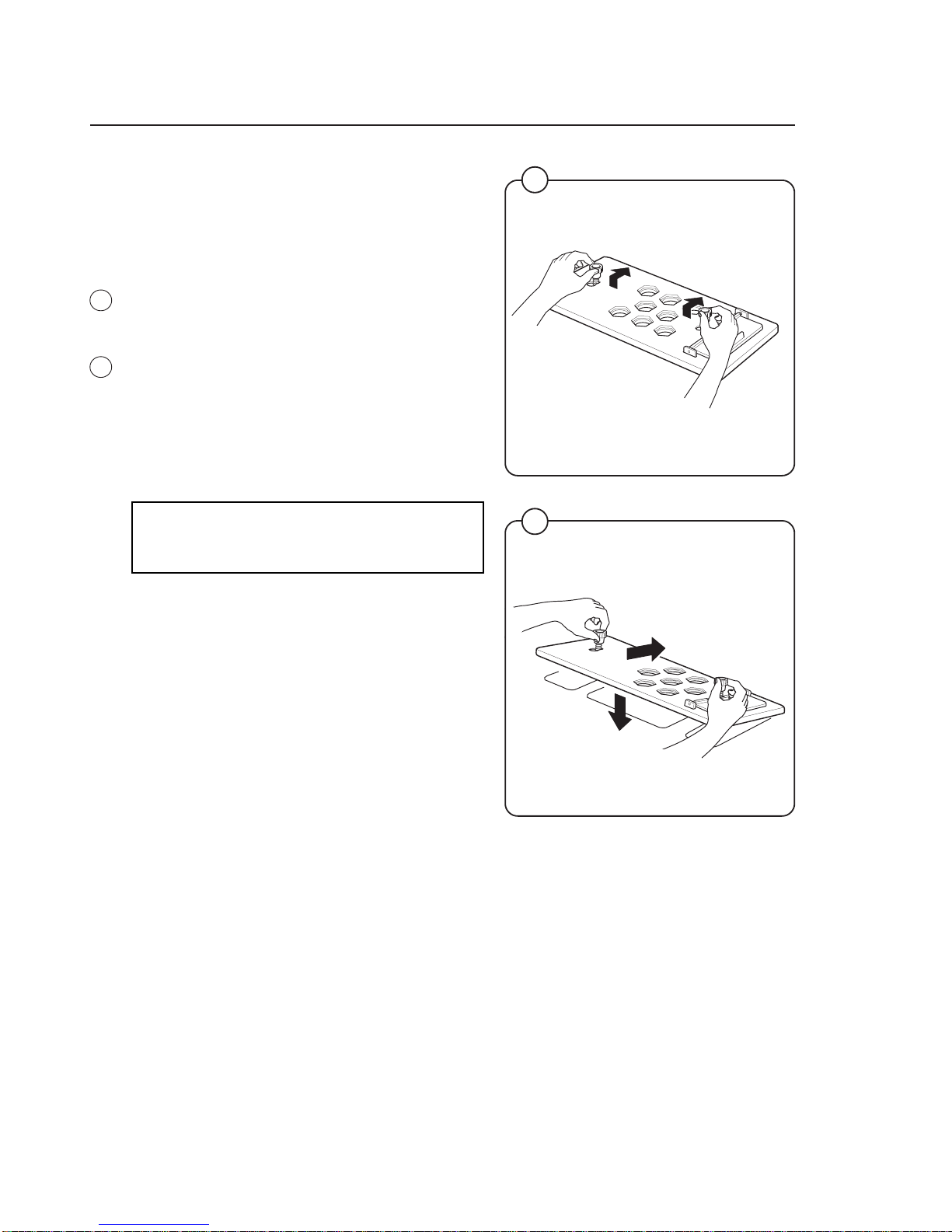
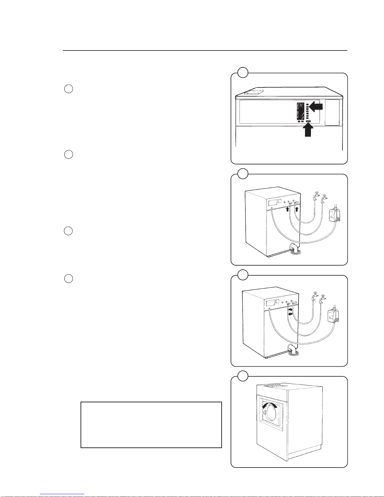
Installing top-mount manifold for
connection of liquid supplies
Remove the lid and lid support from over the
soap box.
Pull the manifold knobs up and forward. The
small hinged lid shall be mounted towards the
front.
1. Loosen both knobs so that one side of the
metal fingers underneath can slide under the
top lid of the machine, within the supply box.
2. Fit the supply injector manifold into the supply
box so that both sides are held securely in
place by the metal fingers, and the small
hinged lid is at the front.
Note:
If the supply injector manifold does not fit turn
it around. You have it in backwards.
Fig.
18
Fig.
19
Cut to fit
on tube
2
1
Multi-rubber ring
20
3647
21
3641
3643
21
Fig.
20
Fig.
21
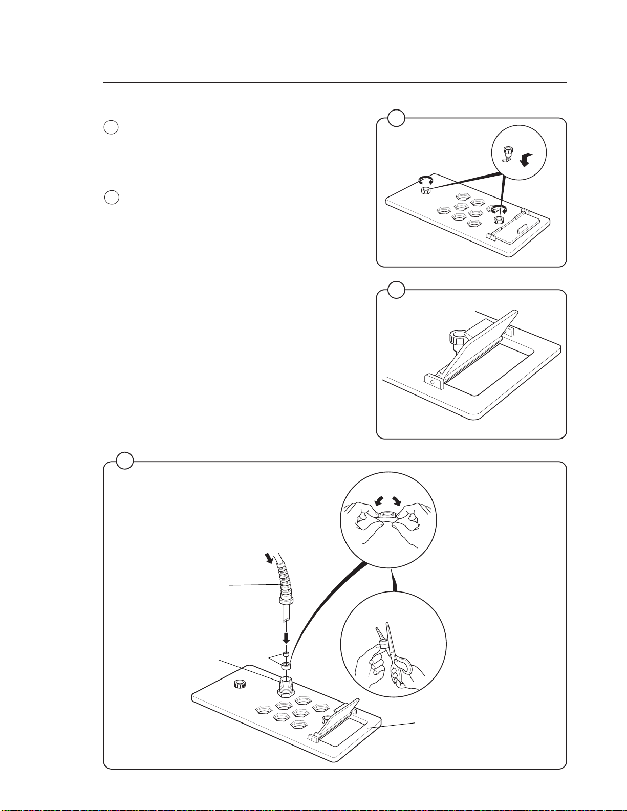
1. Drop the knob into the larger opening in the
supply injector manifold.
2. Tighten securely. Do not overtighten!
Do not use pliers or other tools to tighten the
knobs!
1. Select the correct size rubber ring which will fit
snugly on the chemical tube you are using.
Ring A is used for tubes with Ø 5/16" (8mm).
2. Use scissors or a razor to carefully cut out the
proper size rubber ring. Wrap the rubber ring
around each tube after threading each tube
through the plastic strain relief. Run the tube
through the compression nut to the bottom of
the soap box compartment. Cut the end of the
tube at an angle. Hand tighten the strain relief
on to the compression nut.
This separate lid allows the addition of powder
detergent in compartment 1.
1
Manifold
Compression nut
A
B
Rubber
rings
Strain relief
Installation 11
Installation
22
23
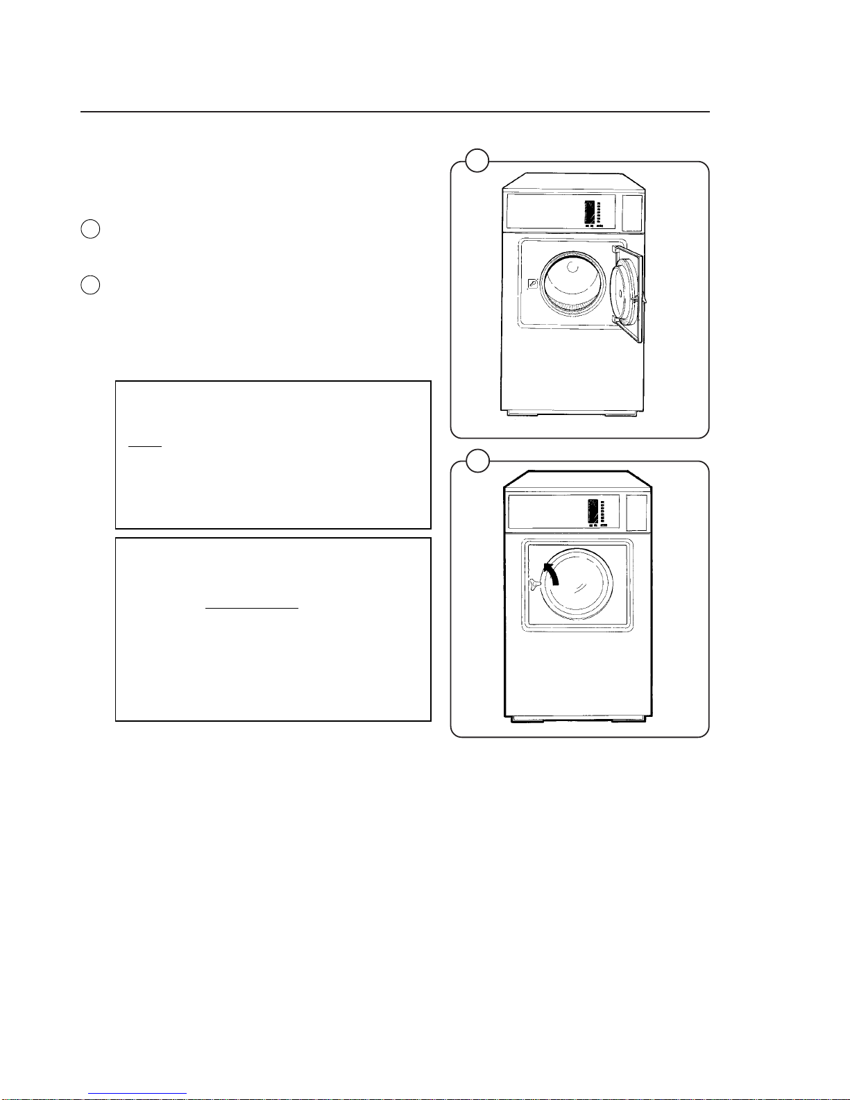
Before the machine is operated, the door safety
interlock must be checked for proper operation
as follows:
• When washer loading door is open, the machine must not start. Verify this by attempting
to start washer with door open.
• When washer is in operation, the loading door
is locked and cannot be opened. Verify this by
attempting to open the loading door when the
machine is operating. If necessary, consult
this manual for proper operation of the door
lock and door safety interlock or call a qualified serviceman.
IMPORTANT:
Door safety interlock must be checked
daily in accordance with above procedure.
WARNING:
Before servicing Wascomat equipment,
disconnect electrical power.
IMPORTANT:
Le verrouillage de sûreté de la porte doit
être vérifié
tous les jours selon la
procédure ci-dessus.
AVERTISSEMENT:
Couper l'alimentation électrique avant
tous travaux d'entretien sur un appareil
Wascomat.
1853
1854
12
Fig.
22
Fig.
23
Installation
26
1295
1835
1836
0958
Function control check-out list
In the machine cylinder, you will find the warranty
registration card, a copy of the warranty policy
and other pertinent material. The warranty card
should be completed and sent to Wascomat. All
other items should be placed in a safe place for
future reference.
The machine should be cleaned when the installation is completed, and checked out as detailed
below without loading the machine with fabrics:
1. Check the incoming power for proper voltage,
phase and cycles.
2. Open manual shut-off valves to the machine.
3. Turn on electric power.
4. Check the door safety interlock as detailed on
page II of this manual.
5. Select the HEAVY SOIL program and then
press the "ON" button for power to the
machine.
6. Run through a complete cycle, checking for
water temperature, drain operation and extract
direction. To advance the timer, press the
START button and hold down until the
indicator arrow reaches the desired part of the
cycle.
7. When the program is in the Break cycle, hot
and cold water should be entering the
machine.
Turn the program selector to MEDIUM SOIL.
The program will rapid advance to the Suds
position and hot water should now enter.
If cold water comes in, the hoses are
improperly connected. Reverse hot and cold
water hoses.
8. Machine must spin in a counter-clockwise
direction, as seen from the front, during
extraction. If it does not, reverse lines L1 and
L3 on 3-phase machines.
NOTE
All machines are factory tested prior to
shipment. Occasionally, some residual
water may be found when the machine is
installed.
24
25
27
Fig.
24
Fig.
25
Fig.
26
Fig.
27
13

Safety rules
14
Safety instructions
• The machine is designed for water washing only.
• The machine must not be used by children.
• All installation operations are to be carried out by qualified
personnel. Licensed personnel are necessary for all electric
power wiring.
• The interlock of the door must be checked daily for proper
operation and must not be bypased.
• All seepage in the system, due to faulty gaskets etc., must be
repaired immediately.
• All service personnel must be fully familiar with the operating
manual before attempting any repair or maintenance of the
machine.
• The machine must not be sprayed with water, otherwise short
circuiting may occur.
• Fabric softeners with volatile or inflammable fluids are not to
be used in the machine.
Consignes de sécurité
• La machine est conçue pour le lavage à l’eau exclusivement.
• La machine ne peut être utilisée par des enfants.
• Tous les travaux d’installation doivent être effectués par une
personne qualifiée. Tous les câblages électriques doivent être
réalisés par un électricien diplômé.
• Le verrouillage du hublot doit être vérifié chaque jour et ne
peut être neutralisé.
• Toute fuite du système, due à des joints défectueux etc., doit
être réparée sans délai.
• Tous les membres du personnel d’entretien doivent être
parfaitement familiarisés avec le manuel d’entretien avant
d’entreprendre une réparation ou un entretien de la machine.
• Ne jamais asperger d’eau la machine sous peine de risquer un
court-circuit.
• Ne pas utiliser dans la machine des adoucissants textiles
contenant des liquides volatils ou inflammables.
15
1855
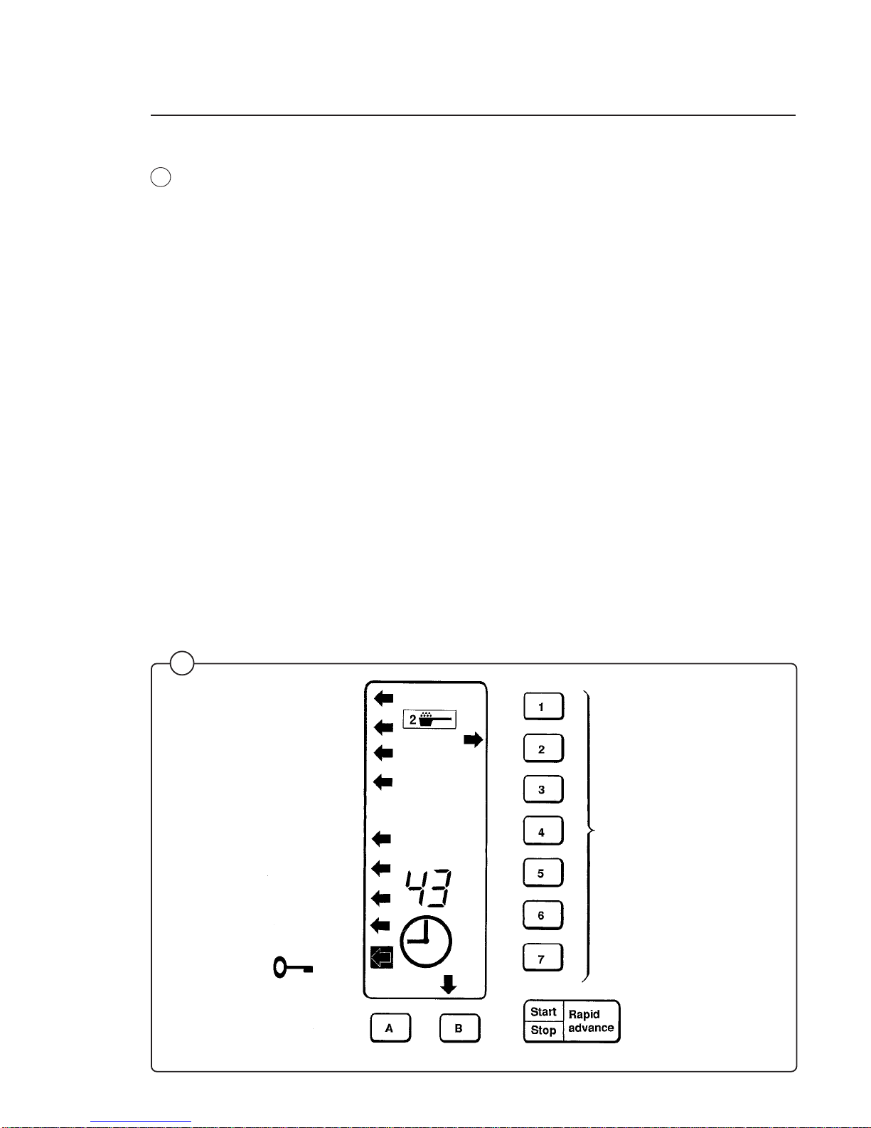
Operating instructions
The keypad has seven program buttons, two programs option buttons and
a combined start, pause and rapid advance button. A display panel with
illuminated symbols shows the chosen program, the functions that have
already occured, those still to occur, and the remaining wash time.
If a fault occurs then indicators will refer the user to the fault list found
under Service Information in this handbook.
Program buttons
Start/Stop/Rapid advance
Program option buttons
28
Fig.
28
16
1856
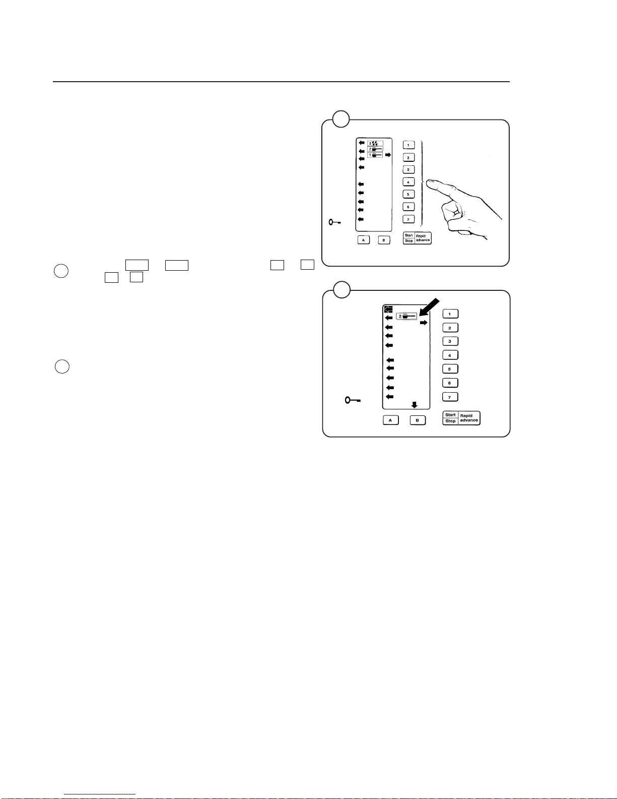
Preparation
Sort the wash according to the choices shown on
the control panel. Check washing tips on garment
labels.
Make sure all pockets are empty and zips are
closed.
Open drum door, load articles and close door.
Wash-program start
• Select wash program. Press correct number
button 1 → 7 and letter button A alt. B
or A + B.
An arrow to the right will light up to show selection. The five lowest arrows to the left will
light to show the stages that will be passed
during the program.
• The five top arrows to the left will indicate which
of the supply pumps will be used during
operation. One window in the display will also
indicate that detergent will be used during the
wash program.
29
Fig.
29
Operating Instructions
1857
30
Fig.
30
 Loading...