

WARNING: ALL OPERATING AND MAINTENANCE PROCEDURES SHOWN ON THE NEXT
PAGE OF THIS MANUAL MUST BE FOLLOWED DAILY FOR PROPER OPERATION OF
YOUR WASCOMAT MACHINE.
PLEASE ENTER THE FOLLOWING INFORMATION AS IT APPEARS ON THE MACHINE(S)
DATA PLATE(S).
MAKE CERTAIN TO KEEP THIS MANUAL IN A SECURE PLACE FOR FUTURE
REFERENCE.
MACHINE TYPE OR MODEL
MACHINE SERIAL NUMBER(S)
ELECTRICAL CHARACTERISTICS:________ VOLTS, _______ PHASE, ______ HZ.
OPERATING & MAINTENANCE MANUAL
FL 125 HI-TEK
FL 185 HI-TEK
471 1562-56/01
95.32

NOTICE TO: OWNERS, OPERATORS AND DEALERS OF WASCOMAT MACHINES
II
IMPROPER INSTALLATION AND INADEQUATE MAINTENANCE, POOR HOUSEKEEPING AND WILLFUL
NEGLECT OR BYPASSING OF SAFETY DEVICES MAY RESULT IN SERIOUS ACCIDENTS OR INJURY.
TO ASSURE THE SAFETY OF CUSTOMERS AND/OR OPERATORS OF YOUR MACHINE, THE FOLLOWING MAINTENANCE CHECKS MUST BE PERFORMED ON A DAILY BASIS.
1. Prior to operation of the machine, check to make certain that all operating instructions and
warning signs are affixed to the machine and legible. (See the following page of this manual
for description and location of the signs.) Missing or illegible ones must be replaced immediately. Be sure you have spare signs and labels available at all times. These can be obtained from your dealer or Wascomat.
2. Check the door safety interlock, as follows:
(a) OPEN THE DOOR of the machine and attempt to start in the normal manner:
For coin-operated models, insert the proper coins to start the machine.
For manually operated models, place the ON-OFF switch in the ON position and
press the Start switch.
For FL and EX models, insert a program card, turn the starter knob to the Start
position and place the ON-OFF switch in the ON position.
For HI-TEK microprocessor models, turn the key switch to the RUN position, choose
a program and press the START button.
For SELECTA 28 models, select a wash program and press the Start button.
THE MACHINE(S) SHOULD NOT START !
(b) CLOSE THE DOOR to start machine operation and, while it is operating, attempt to
open the door without exerting extreme force on the door handle. The door should
remain locked!
If the machine can start with the door open, or can continue to operate with the door
unlocked, the door interlock is no longer operating properly. The machine must be
placed out of order and the interlock immediately replaced.
(See the door interlock section of the manual.)
3. DO NOT UNDER ANY CIRCUMSTANCES ATTEMPT TO BYPASS OR REWIRE ANY OF
THE MACHINE SAFETY DEVICES AS THIS CAN RESULT IN SERIOUS ACCIDENTS.
4. Be sure to keep the machine(s) in proper working order: Follow all maintenance and
safety procedures. Further information regarding machine safety, service and parts can be
obtained from your dealer or from Wascomat through its Teletech Service Telephone - 516/
371-0700.
All requests for assistance must include the model, serial number and electrical characteristics as
they appear on the machine identification plate. Insert this information in the space provided on the
previous page of this manual.
5. WARNING: DO NOT OPERATE MACHINE(S) WITH SAFETY DEVICES BYPASSED, REWIRED OR
INOPERATIVE! DO NOT OPEN MACHINE DOOR UNTIL DRUM HAS STOPPED ROTATING!
SAFETY AND WARNINGS SIGNS
Replace If Missing Or Illegible
One or more of these signs must be affixed on each machine as indicated, when not included as part of the front instruction panel.
LOCATED ON THE OPERATING INSTRUCTION SIGN OF THE MACHINE:
LOCATED AT THE REAR OF THE MACHINE:
INSTALLATION AND MAINTENANCE WARNINGS
1. This machine MUST be securely bolted to an uncovered concrete floor, according to
the installation instructions, to reduce the risk of fire and to prevent serious injury, or
damage to the machine.
2. If installed on a floor of combustible material, the floor area below this machine must
be covered by a metal sheet extending to the outer edges of the machine.
3. This machine MUST be connected to a dedicated electrical circuit to which no other
lighting unit or general purpose receptacle is connected. Use copper conductor only.
4. This machine MUST be serviced and operated in compliance with manufacturer's
instructions. CHECK DOOR LOCKS EVERY DAY FOR PROPER OPERATION TO PRE
VENT INJURY OR DAMAGE. IF THE DOOR LOCK FAILS TO OPERATE PROPERLY,
PLACE THE MACHINE OUT OF ORDER UNTIL THE PROBLEM IS CORRECTED.
5. Disconnect power prior to servicing of machine.
6. To remove the top panel for service on those models on which it is secured by screws
at the rear, first remove the screws. Be certain to reinstall them when remounting the
top panel. To remove the top panel for service on those models on which it is secured
by one or two keylocks, use the keys originally shipped in the drum package. Be
certain to relock after remounting the top panel.
MANUFACTURED BY WASCATOR
DISTRIBUTED BY WASCOMAT INWOOD, NEW YORK, USA
LOCATED ON THE DOOR:
DO NOT ATTEMPT TO OPEN DOOR
UNTIL PROGRAM HAS FINISHED AND
DRUM HAS STOPPED ROTATING.
WARNING !
If you need to order more safety or warning
signs, call Wascomat's parts department at
516-371-2000, or call your local dealer.
471 7651-17
CAUTION
1. Do not open washer door until cycle is completed, operating
light is off, and wash cylinder has stopped rotating.
2. Do not tamper with the door safety switch or door lock.
3. Do not attempt to open door or place hands into washer to
remove or add clothes during operation. This can cause
serious injury.
MACHINE SHOULD NOT BE USED BY CHILDREN
PRECAUCION
1. No abra la puerta de la máquina lavadora sino hasta que la
máquina haya terminado su ciclo, la luz operativa esté apaga
da y el cilindro de lavado haya completamento terminado de
girar.
2. No interferia o manipule el switch o la cerradura de la puerta.
3. No trate de abrir la puerta o meta las manos dentro de la
máquina para meter o sacar ropa mientras la máquina está
en operación, pues puede resultar seriamento herido.
LAS MÁQUINAS NO DEBEN SER USADAS POR NIÑOS
471 76 62 03-01

21
FLEX-O-MATIC FL 125, FL 185 HI-TEK
Contents
Introduction ......................................................................1
Technical data.................................................................. 2
Installation ........................................................................5
Safety rules ....................................................................15
Mechanical and electrical design ................................... 16
Procedure for use...........................................................31
Programming..................................................................38
Service information ........................................................ 60
Maintenance...................................................................61
Safety instructions
• All installation operations are to be carried out by qualified
personnel. Licensed personnel are necessary for all electric
power wiring.
• This machine is designed for water washing only.
• This machine must not be used by children.
• This machine must not be sprayed with water, otherwise short
circuiting may occur.
• Fabrics softener with volatile or inflammable fluids are not to
be used in the machine.
• The interlock of the door must be checked daily for proper
operation and must not be bypased.
• All service personnel must be fully familiar with the operating
manual before attempting any repair or maintenance of the
machine.
• Any leakage in the system, due to faulty gaskets etc., must be
repaired immediately.
The manufacturer reservs the right to make changes to design and
material specifications.
1
Introduction
Introduction
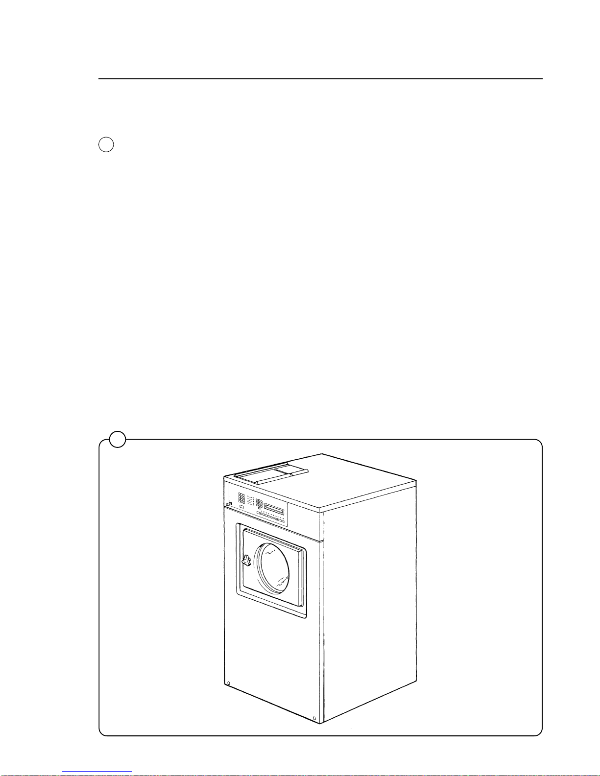
The FL HI-TEK model washer/extractors have been developed to cover the
heavy duty requirements of hotels, motels, nursing homes, hospitals,
professional laundries, restaurants, airlines, ships, schools, colleges and all
on-premises laundries where flexibility and quick formula variation coupled
with high quality automatic washing are required.
The microcomputer controlled FL HI-TEK model allows for complete
programming of water temperatures, water levels, wash and extraction
periods and supply injections. The machine is designed for connection to
hot and cold water supplies and may be used with free-standing powder or
liquid supply injectors which can be activated by signals from the machine.
All parts of the machine which come into contact with the items being
washed are made of heavy gauge surgical stainless steel, ensuring long life
and lasting beauty, as well as full protection for no-iron fabrics. All electrical
components are made accessible for servicing by simply removing the top
panel.
This manual contains a technical description of the machine and instructions for its installation, operation and maintenance. Together with the
wiring diagram which accompanies each individual machine it should be
kept in a safe place for easy reference.
When ordering spare parts or contacting the manufacturer for any purpose
always give the machine serial number, model, voltage and other electrical
characteristics appearing on the dataplate at the rear of the machine.
1718
1
Fig.
1

2
Technical data
Technical data FL 125 HI-TEK
Dry load capacity up to 35 lbs
Overall dimensions Width 775 mm 30 1/2 in
Depth 995 mm 39 3/16 in
Height 1196 mm 47 3/32 in
Net weight 210 kg 462 lbs
Dyn force 2.4 ± 4.8 kN 576 ±
1152 lbs force
Crated dimensions Volume 1,06 m
3
39 cu.ft
Weight 222 kg 489 lbs
Inner drum dimensions Diameter 620 mm 24 1/2 in
Depth 520 mm 20 1/2 in
Volume 157 litre 5.65 cu.ft
Speed of rotation Wash 52 r.p.m.
Extraction 500 r.p.m.
G-factor During wash 0.9
During extraction 87
Motor speed During wash 330 r.p.m.
During extraction 3450 r.p.m.
Voltage requirements Choice:
208-240 V 1-Phase 60 Hz or
208-240 V 3-Phase 60 Hz
Rated output power Motor, wash, 300 W
0.4 HP
Motor, extract. 3-phase 1300 W
1.8 HP
Motor, wash 1-phase 280 W
0.4 HP
Motor, extract. 1-phase 1300 W
1.8 HP
Overcurrent protection Three-phase 15 A
Single-phase 20 A
Water connections
Recommended water pressure 2 - 6 kp/cm
2
25 - 85 psi
Hose connection, water DN 20 3/4"
Hose connection, drain 74 mm 3"

3
Technical data
Technical data FL 185 HI-TEK
Dry load capacity up to 23 kg 50 lbs
Overall dimensions Width 860 mm 33 7/8 in
Depth 1085 mm 42 3/4 ın
Height 1315 mm 51 3/4 in
Net weight 264kg 582 lbs
Dyn force 3.1 ± 5.2 kN 744 ±
1248 lbs force
Crated dimensions Volume 1,42 m
3
50.2 cu.ft.
Weight 275 kg 606 lbs
Inner drum Diameter 700 mm 27 9/16 in
Depth 600 mm 23 5/8 in
Volume 230 litre 8.1 cu.ft
Speed of rotation Wash 45 r.p.m.
Extraction 455 r.p.m.
G-factor During wash 0.8
During extraction 81
Motor speed During wash 360 r.p.m.
During extraction 3480 r.p.m.
Voltage requirements Choice:
208-240 V 3-Phase 60 Hz or 208-240 V 1 -phase 60 Hz
Rated output power Motor, wash, 3-phase 400 W 0.55 HP
Motor, extract, 3-phase 2000 W 2.7 HP
Motor, wash 1-phase 400 W 0.55 HP
Motor, extract, 1-phase 1800 W 2.4 HP
Overcurrent protection Three-phase 15 A
Single-phase 20 A
Water connections
Recommended water pressure 2-6 kp/cm
2
25-85 psi
Hose connection, water DN 20 3/4"
Hose connection, drain 74 mm 3"

4
Outline and dimensions
Technical data
FL 125HI-TEK FL 185HI-TEK
mm inches mm inches
A 1196 47 1/16 1315 51 3/4
B 465 18 5/16 540 21 1/4
C 775 30 1/2 860 33 7/8
D 995 39 3/16 1085 42 11/16
E 205 8 1/16 205 8 1/16
F 160 6 5/16 160 6 5/16
G 1040 40 15/16 1160 45 11/16
H 1035 40 3/4 1155 45 1/2
J 100 3 15/16 100 3 15/16
K 270 10 5/8 260 10 3/8
L - - 295 11 5/8
M - - 1215 47 13/16
N 1135 44 11/16 1255 49 7/16
1 Drain outlet
1
1852
FL 185
1
FL 125
5
Installation
2
3
4
0271
1677
1132
FL125 HI-TEK FL185 HI-TEK
mm inches mm inches
A 508 20 600 23 2/3
B 910 35 13/16 960 37 3/4
C 1031 37 13/32 1000 39 3/8
D 142 5 9/16 142 5 9/16
E 600 23 5/8 700 27 9/16
G 800 31 1/2 880 34 2/3
H 786 30 15/16 922 36 1/8
I 991 39 1090 42 7/8
K 281 11 236 9 7/16
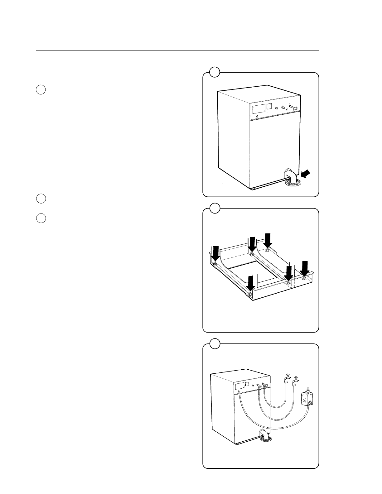
Installation
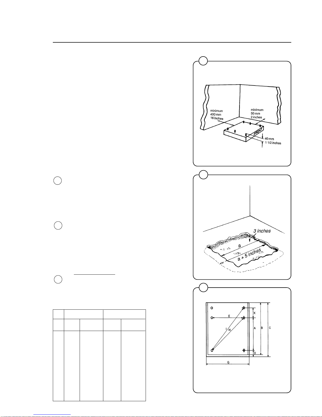
Machine foundation
The machines are designed to be bolted in
position to a concrete floor or specially prepared
concrete foundation. A template showing the size
of the foundation and positioning of the
foundation bolts is delivered with each machine.
For installation on an existing concrete floor, the
floor must be at least 8" thick and of good quality.
If the floor does not meet these requirements,
then a 6-8" high concrete foundation should be
made. A prefabricated steel base is available for
mounting of machines without an additional
foundation.
Follow the instructions below when making a
concrete foundation:
1. Decide where to place the machine and
consider maintenance requirements, i.e.
determine a suitable distance from the rear of
the foundation to the wall, and the distance
from the foundation to the nearest side wall.
The distance should be at least 16 and 12
inches, respectively.
2. Break up the floor to a depth of 3 inches,
making sure that the sides of the hole slope
inwards - the bottom of the hole should be 5
inches longer than the upper length.
3. Wet the hole well. Brush the bottom and sides
with cement grout.
4. Prepare a casing and fill with concrete to form
foundation. Make sure the foundation is level.
5.
Use the template to position the foundation
bolts correctly - bolts are to extend 1 1/2"
above concrete.
NOTE: A prefabricated steel frame, designed
to be placed in the concrete instead of the
individual mounting bolts, is available.
Fig.
4
Fig.
3
Fig.
2
B = machine outline to edge of front panel
C, G = minimum foundation pad for one machine
6
Installation
5
0274
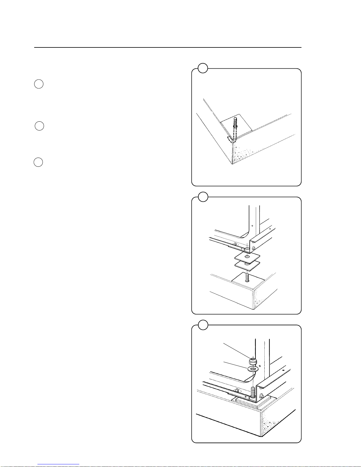
Mechanical installation
• Place wide steel shims on the concrete foundation over the bolts.
• Lift the machine and lower it in position. Never
use the door or the door handle to lift or lower
the machine.
• Check that the machine is level front-to-rear
and side-to-side and standing firmly on the
six supporting points. Spacing washers must
be mounted if one or more of these points is
not resting against the floor/foundation.
• Place flat washers over the foundation bolts
and secure the machine in position by tightening the self-locking nuts. See illustration
below.
• Check and tighten the nuts every week for the
first month.
Fig.
5
7
1133
selflocking
nut
flat washer
6
0950
Fig.
7
Fig.
6
7
Installation
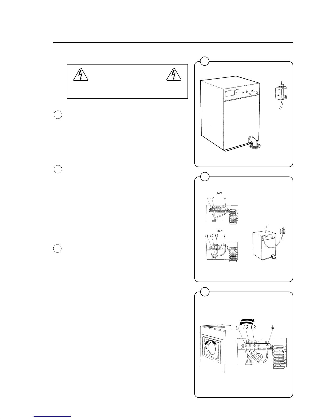
Electrical installation
All electrical installations are to be carried
out by licensed personal.
Although the machines are fitted with a thermal
overload in the motor windings and a separate
fuse for the control circuit, a separate threephase common-trip circuit breaker must be
installed for all three-phase machines.
For proper overcurrent protection, check the data
plate at the rear of the machine. Also consult
local electrical code for special requirements.
Connect L1, L2, L3 and ground wires according
to the markings of the terminal block. The cable
is to hang in a large loose loop, supported by the
clip of the terminal block.
Make sure the machine is properly grounded
electrically.
After installation, do the following for 3-phase
machines
Check the incoming power for a high voltage leg.
If present, connect that line to L2 on the terminal
block.
Start the machine and check that the drum
rotates in the proper direction during extraction,
i.e. counter-clockwise when seen from the front.
If the drum rotates in the wrong direction intercharge line L1 and L3 at the power connection
terminal.
Fig.
9
Fig.
10
Fig.
8
1830
8
1838
9
1839
10
8
Installation
11
1832
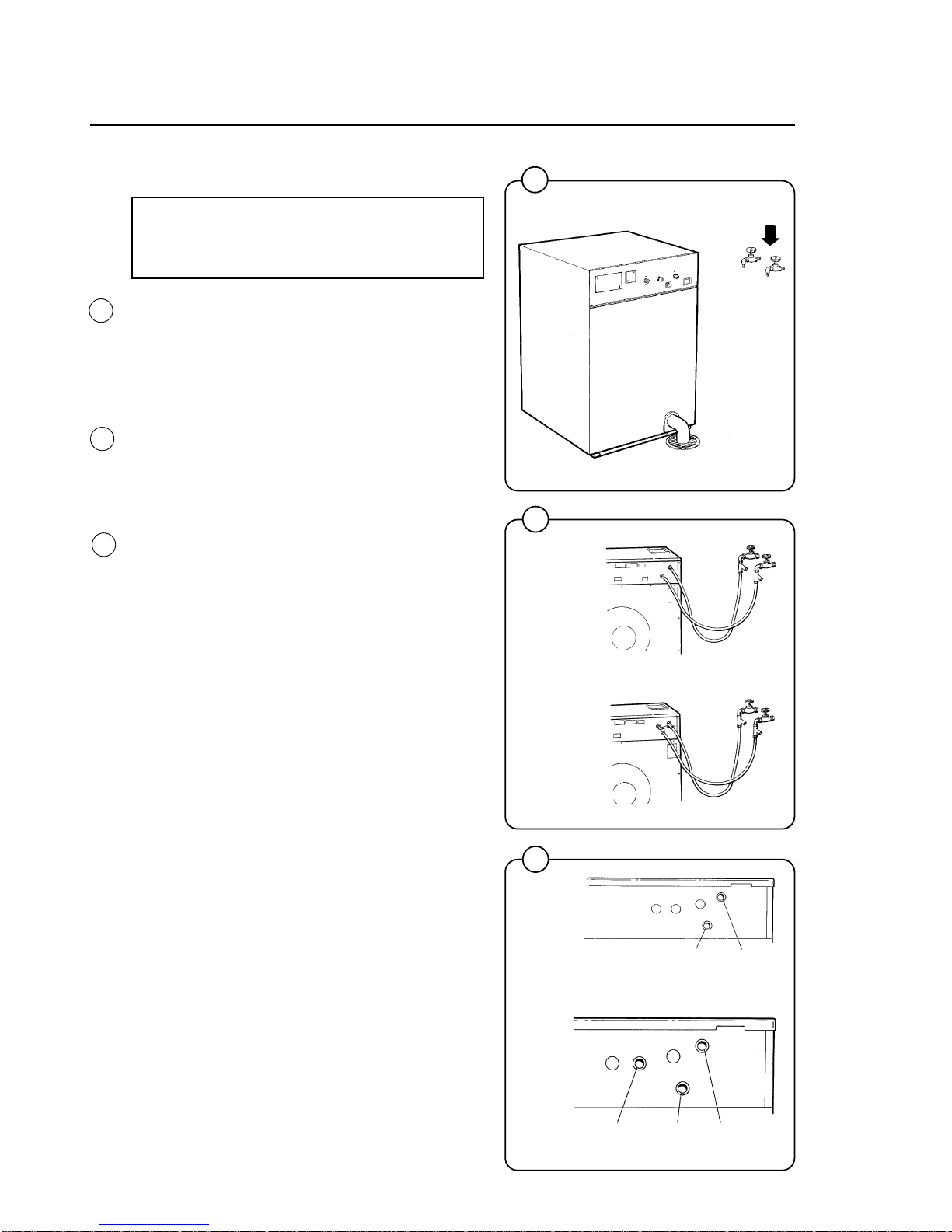
Water connection
NOTE
All plumbing must conform to national
and local plumbing codes.
Incoming water lines do not require non-return or
back-suction valves, as the machine is already
fitted with a siphon breaker. However, all incoming lines must be fitted with shut-off valves.
• Use flexible water hoses of proper length to
avoid sags and kinks.
• Water inlets are labelled for hot and cold
water connection.
• Flush the water system thoroughly and check
that the filter at the machine inlet is fitted
correctly.
• Connect the machine to the water mains with
3/4" reinforced rubber hosing not to exceed 6
ft in length. Hang the hosing in a large loop.
Do not use rigid piping.
Fig.
11
Fig.
12
Fig.
13
13
FL 125
HI-TEK
1846
hot water cold water
FL185
HI-TEK
1844
hot water cold water hot water
(to detergent supply box)
12
1870
FL185
HI-TEK
FL 125
HI-TEK
9
Installation
14
0956
Steam connections (optional)
The steam supply to the machine should be fitted
with manual shut-off valves and filters to facilitate
installation and servicing.
Fit the filter supplied to the manual cut-off valve.
Connection size at filter: DN 15 (BSP 1/2'').
Steam pressure required:
• minimum: 10 psi (0.5 kp/cm
2
)
• maximum: 115 psi (8 kp/cm
2
)
Check there are no sharp angles or bends in the
connection hose.
For steam pressures in excess of 85 psi, the
nozzle supplied should be installed between the
stem injector and the steam hose. The nozzle is
installed inside the steam injector.
15
2171
Fig.
14
Fig.
15
10
Installation
16
1833
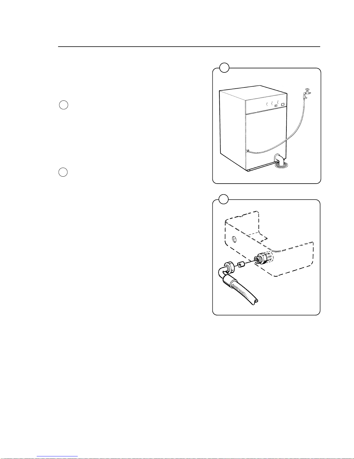
Drain connection
Connect a 3" (75 mm) flexible hose to the drain
outlet of the machine.
The drain hose must not have sharp bends and
must slope from the machine to assure proper
drainage. The outlet must open freely to the main
drains.
Do not reduce the size of the drain connection
from the machine to the waste line.
Start-up and safety checklist
Before initial start-up of a Wascomat washerextractor, the following safety checks must be
performed:
• Make sure the machine is properly bolted to
the floor.
• Make sure that all electrical and plumbing
connections have been made in accordance
with applicable local codes.
• Make sure the machine is properly grounded
electrically.
Fig.
16
Fig.
17
Fig.
18
18
1869
17
1140
11
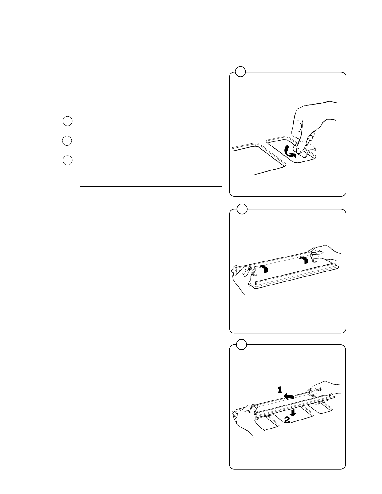
Connection of external liquid
supply
Remove cover and cover support over the soap
box.
Bend all the way back the metal plate in
compartment 3.
Pull the knobs up and forward.
1. Loosen both knobs so that one side of the
metal fingers underneath can slide under the
top lid of the machine, within the supply box.
2. Fit the supply injector into the supply box so
that both sides are held securely in places by
the metal fingers.
Note:
If the supply injector does not fit turn it around.
You have it in backwards.
Installation
19
1336
Fig.
19
Fig.
20
Fig.
21
21
1333
20
1334
12
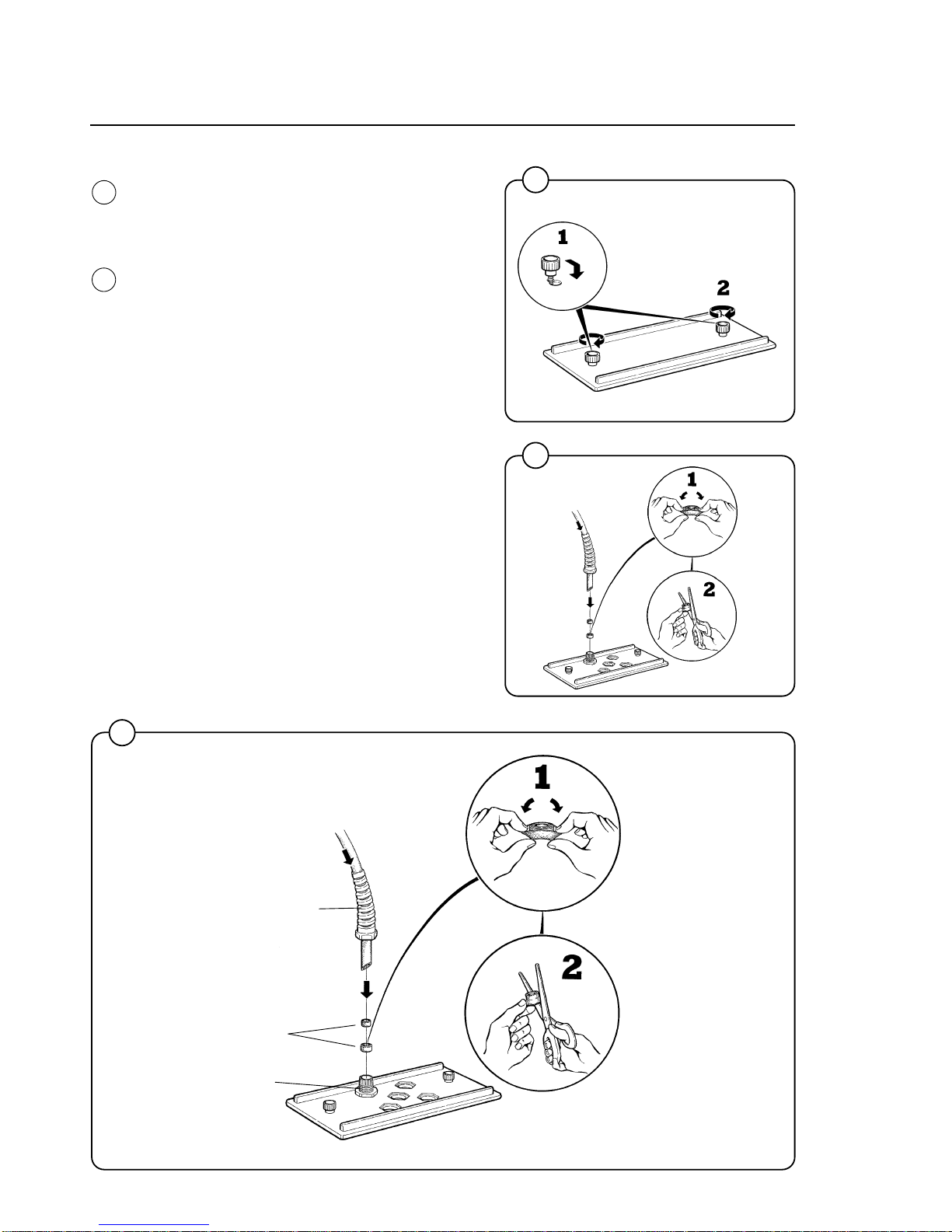
1. Drop the knop into the larger opening in the
supply injector lid.
2. Tighten securely. Do not overtighten! Do not
use pliers or other tools to tighten the knobs!
1. Stretch the multi-rubber ring B and select the
correct size ring which will fit snugly on the
chemical tube you are using. Ring A is used
for tubes with Ø1/3'' (8 mm).
2. Use scissors or a razor to carefully cut out the
proper size rubber ring. Wrap the rubber ring
around each tube after threading each tube
through the plastic nipple. Run the tube
through the compression nut to the bottom of
the compartment. Cut the end of the tube at an
angle. Hand tighten the plastic nipple on to the
compression nut.
Installation
Fig.
22
Fig.
23
22
23
1332
1331
23
1331
Supply injector
Cut to fit
on tube
Multi-rubber ring
Plastic
nipple
Rubber A
rings B
Compression
nut

13
Electrical connection
At the electrical connection of the machine are
two quick connectors. When the machine is
delivered connector A is connected. When using
powder supply, change to connector B.
Pump connection
To the right of the incoming power connection
block is the connection strip for pumps.
Depending on the number of pumps to be
connected, they shall be connected from 1-5 and
C (common) on resp. connection. The pumps
obtain signals from the electronic timer via the
connections.
Installation
24
1932
25
1922
Fig.
24
Fig.
25
14
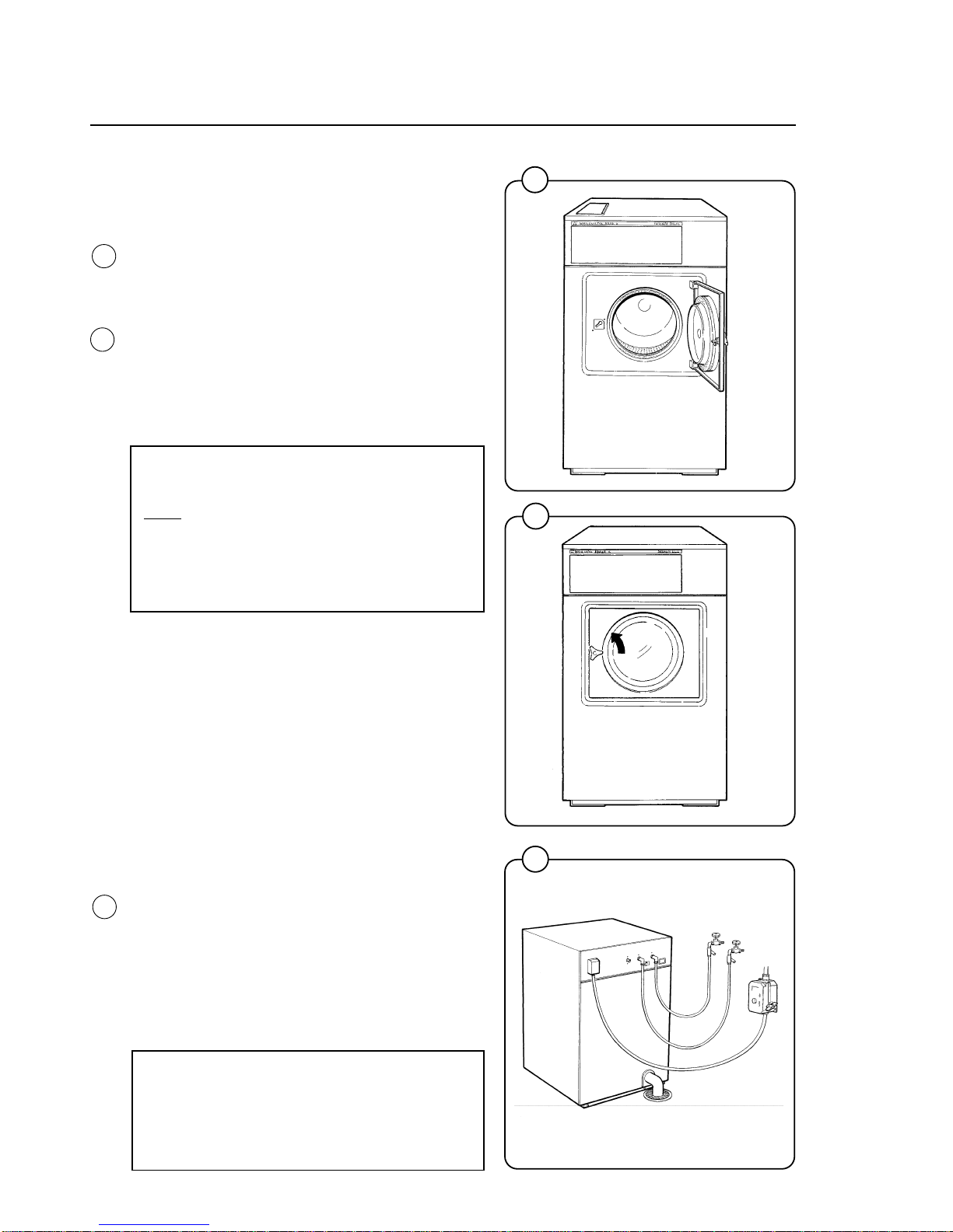
Installation
26
Before the machine is operated, the door safety
interlock must be checked for proper operation
as follows:
• When washer loading door is open, the
machine must not start. Verify this by attempting to start washer with door open
(see section ”Procedure”).
• When washer is in operation, the loading door
is locked and cannot be opened. Verify this by
attempting to open the loading door when the
machine is operating. If necessary, consult
this manual for proper operation of the door
lock and door safety interlock or call a qualified serviceman.
IMPORTANT:
Door safety interlock must be checked
daily in accordance with above procedure.
WARNING:
Before servicing Wascomat equipment,
disconnect electrical power.
Function control check-out list
In the machine cylinder, you will find the warranty
registration card, a copy of the warranty policy,
the bolt hole template and other pertinent materia. The warranty card should be completed and
sent to Wascomat. All other items should be
placed in a safe place for future reference.
The machine should be cleaned when the installation is completed, and checked out as detailed
below without loading the machine with fabrics:
1. Check the incoming power for proper
voltage, phase and cycles.
2. Open manual shut-off valves to the machine.
3. Turn on electric power.
4. Check the function of the door safety
interlock as detailed on page 13 of this
manual.
5. Run through a complete cycle, checking for
water temperature, drain operation and
extract direction.
NOTE
All machines are factory tested prior to
shipment. Occasionally, some residual
water may be found when the machine is
installed.
1722
1723
Fig.
28
Fig.
27
Fig.
26
1141
27
28

15
Safety rules
• All installation operations are to be carried out by qualified
personnel. Licensed personnel are necessary for all electric
power wiring.
• This machine is designed for water washing only.
• This machine must not be used by children.
• This machine must not be sprayed with water, otherwise short
circuiting may occur.
• Fabric softeners with volatile or inflammable fluids are not to be
used in the machine.
• The interlock of the door must be checked daily for proper
operation and must not be bypassed.
• All service personnel must be fully familiar with the operating
manual before attempting any repair or maintenance of the
machine.
• Any leakage in the system, due to faulty gaskets etc., must be
repaired immediately.
Safety rules

16
Mechanical and electrical design
General
The door and the electronic timer with display and keyboard are fitted at the
front of the machine.
All control and indicating components, i.e. relays, level control, etc are
assembled under the top cover, easily accessible from the top of the
machine for simplified servicing.
Main units
1. Electronic timer with display and keyboard for operating the machine.
2. Door – with automatic locking device which remains locked throughout
the different wash processes.
3. Detergent supply box - three compartments for automatic injection of
powdered detergents and fabric softener.
4. Inner cylinder - of stainless steel supported at the rear by two
ballraces.
5. Outer drum - of stainless steel (18/8) securely attached to the frame.
6. Wash motor – for reversing wash action and high speed spin action,
with self tensioning V-belt drive and rubber suspension.
7. Hot and cold water valves - program and level controlled solenoid
valves for filling with water, and for flushdown of automatic detergent
dispenser.
8. Drain valve - timer controlled for draining the machine of water.
9. Siphon breaker - to prevent water in the machine from re-entering the
water supply system.
10. Control unit - plug-in type for time and temperature control of the
different wash cycles.
Fig.
29
 Loading...