

Page 1
MCS-605-1 Pivot Point Tension Sensor for
Warner Electric Tension Control System
P-362
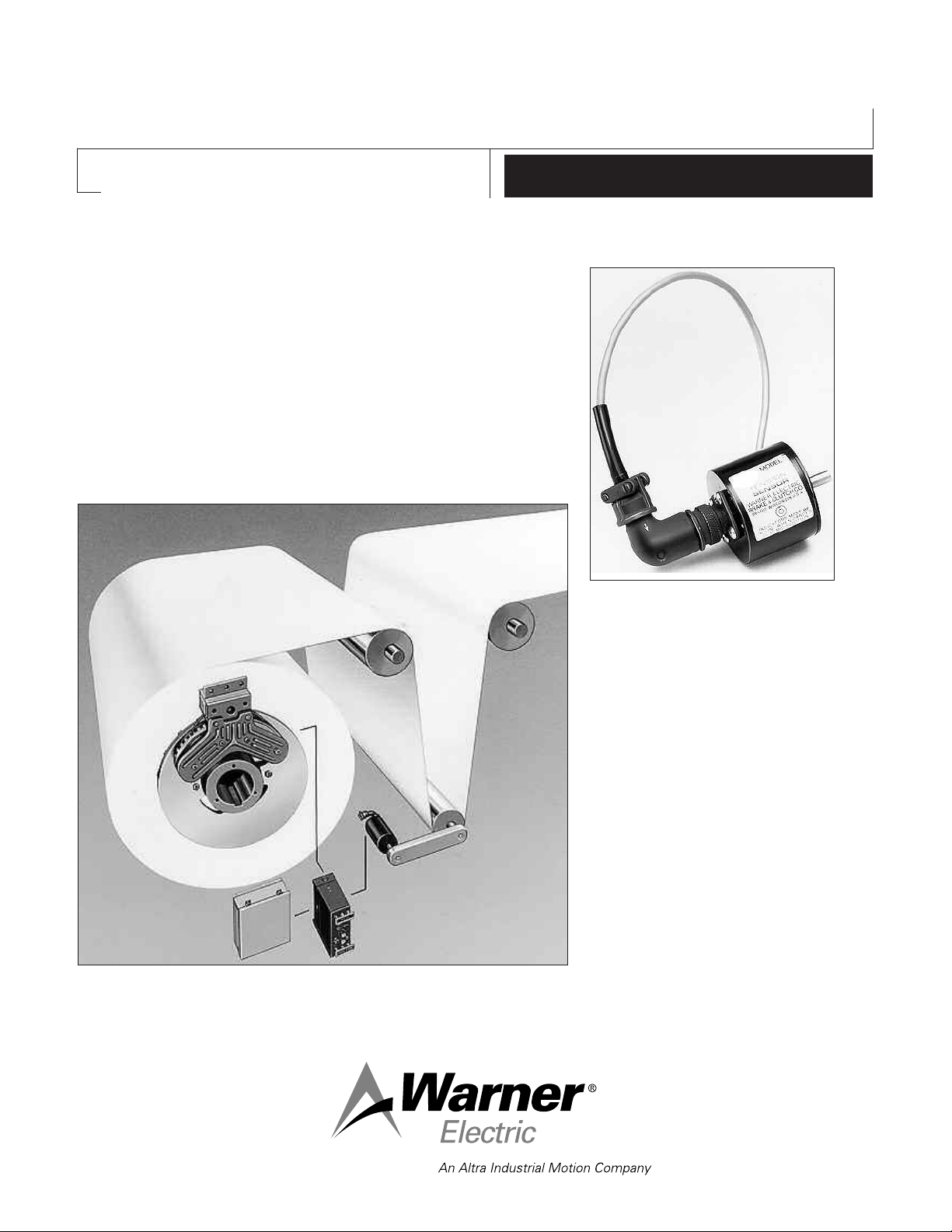
The MCS-605-1 Tension Sensor is used with the
Warner Ten sion Control System to provide smooth
control of un wind stands op er at ing at any speed.
The sensor is especially con ve nient in applications
hav ing small dancer arms and is com plete with
versatile mounting brack ets. The pivot point sen sor does not add additional weight to the dancer
arm.
Installation Instructions
MCS-605 Pivot Point Sensor
MCS-605 Pivot Point Sensor
A Complete Dancer System
• For Unwind Stands
• Dancer Roll System
• Stable
• Electromagnetic Brakes
• Quiet
• Closed Loop Control
• Off-the-shelf Availability from your
local Warner Dis trib u tor
Page 2
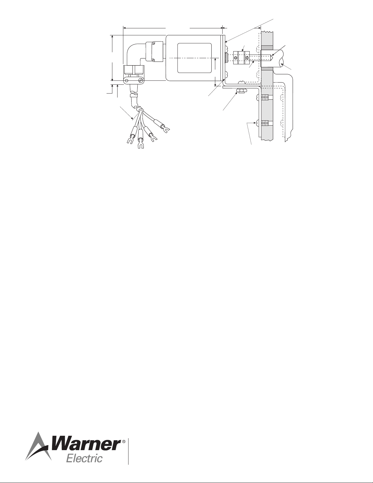
Bracket (see note 1)
.250/.253 Dia.
1/2 Deep
Dancer
Pivot
Shaft
1-11/16 Nom.
Coupling
Supplied
Pin Supplied
8-32 Screws
(3 supplied)
1-1/4
10-32 Screws
Washers & Nuts
(2 supplied)
3 Holes 3/16 Dia. on
1.50 B.C. Equally
Spaced
NOTES:
1. TWO BRACKETS ARE SUPPLIED
WITH EACH UNIT SO THAT THE
CUSTOMER CAN MOUNT THE
MCS-605-1 ACCORDINGLY.
2. BRACKETS ARE MADE FROM
14 GAUGE (.0747) STEEL.
15' Jacket
5/16
2 Dia.
4-3/8
Dimensions/Installation
1. Using a 1/4" drill, drill a hole in the center of the
dancer pivot shaft 1/2" deep.
2. Drive the supplied pin into the hole in the shaft
until half its length remains exposed.
3. Assemble the brackets and mount the
sensor on the bracket.
4. Position the sensor and bracket on the
machine so the sensor shaft and the pin are
aligned and sep a rat ed by 1/8 to 1/4 inch.
While holding the sensor and bracket in the
above position, mark the centers of the bracket
holes on the machine. Drill and tap holes in the
machine for 8-32 screws.
5. Connect the sensor shaft to the pin with the
flexible coupling provided. The index mark on
the sensor shaft must be aligned with the index
mark on the sensor face when the dancer arm
is near the midtravel position.
6. Mount the sensor and bracket to the machine.
Con nect the sensor to the tension control unit
with the cable as sem bly in accordance with the
instructions supplied with the control unit.
P-362 06/11 Printed in USA
Warner Electric LLC warrants that it will repair or replace (whichever it deems
advisable) any product manufactured and sold by it which proves to be defective in
material or workmanship within a period of one (1) year from the date of original
purchase for consumer, commercial or industrial use.
This warranty extends only to the original purchaser and is not transferable or
assignable without Warner Electric LLC’s prior consent.
Warranty service can be obtained in the U.S.A. by returning any defective product,
transportation charges prepaid, to the appropriate Warner Electric LLC factory.
Additional warranty information may be obtained by writing the Customer
Satisfaction Department, Warner Electric LLC, 449 Gardner Street, South Beloit,
Illinois 61080, or by calling 815-389-3771.
A purchase receipt or other proof of original purchase will be required before warranty
service is rendered. If found defective under the terms of this warranty, repair or
replacement will be made, without charge, together with a refund for transportation
costs. If found not to be defective, you will be notified and, with your consent, the
item will be repaired or replaced and returned to you at your expense.
This warranty covers normal use and does not cover damage or defect which
results from alteration, accident, neglect, or improper installation, operation, or
maintenance.
Some states do not allow limitation on how long an implied warranty lasts, so the
above limitation may not apply to you.
Warner Electric LLC’s obligation under this warranty is limited to the repair or
replacement of the defective product and in no event shall Warner Electric LLC be
liable for consequential, indirect, or incidental damages of any kind incurred by
reason of the manufacture, sale or use of any defective product. Warner Electric
LLC neither assumes nor authorizes any other person to give any other warranty or
to assume any other obligation or liability on its behalf.
WITH RESPECT TO CONSUMER USE OF THE PRODUCT, ANY IMPLIED
WARRANTIES WHICH THE CONSUMER MAY HAVE ARE LIMITED IN DURATION
TO ONE YEAR FROM THE DATE OF ORIGINAL CONSUMER PURCHASE. WITH
RESPECT TO COMMERCIAL AND INDUSTRIAL
USES OF THE PRODUCT, THE FOREGOING WARRANTY IS IN LIEU OF AND
EXCLUDES ALL OTHER WARRANTIES, WHETHER EXPRESSED OR IMPLIED BY
OPERATION OF LAW OR OTHERWISE, INCLUDING, BUT NOT LIMITED TO, ANY
IMPLIED WARRANTIES OF MERCHANTABILITY OR FITNESS.
Some states do not allow the exclusion or limitation of incidental or consequential
damages, so the above limitation or exclusion may not apply to you. This warranty
gives you specific legal rights and you may also have other rights which vary from
state to state.
Changes in Dimensions and Specifications
All dimensions and specifications shown in Warner Electric catalogs are subject to
change without notice. Weights do not include weight of boxing for shipment.
Certified prints will be furnished without charge on request to Warner Electric.
Warner Electric LLC
31 Industrial Park Road • New Hartford, CT 06057
815-389-3771 • Fax: 815-389-2582
www.warnerelectric.com
Warranty
 Loading...