

Page 1

Warner Photoscanner MCS-500 Series
LED Photoelectric Control
P-241-100
819-0504
Installation & Operating Instructions
Page 2

Contents
Description . . . . . . . . . . . . . . . . . . . . . . . . . . . . . . 2
Specifications . . . . . . . . . . . . . . . . . . . . . . . . . 2 - 3
Installation . . . . . . . . . . . . . . . . . . . . . . . . . . . . . . . 3
Modules And Output Wiring . . . . . . . . . . . . . . . . . 3
Timing Adjustment . . . . . . . . . . . . . . . . . . . . . . . . 4
Maintenance . . . . . . . . . . . . . . . . . . . . . . . . . . . . . 4
Part Numbers . . . . . . . . . . . . . . . . . . . . . . . . . . . . 4
Complete Retroreflective Units . . . . . . . . . . . . . . . 4
Modules and Options . . . . . . . . . . . . . . . . . . . . . . 4
Dimensions . . . . . . . . . . . . . . . . . . . . . . . . . . . . . . 5
Bracket . . . . . . . . . . . . . . . . . . . . . . . . . . . . . . . . . 5
Warranty. . . . . . . . . . . . . . . . . . . . . . . . . Back Page
Failure to follow these
instructions may result in product damage,
equipment damage, and serious or fatal
injury to personnel.
Description
The MCS-500 is a series of completely self-contained photoelectric controls with LED light
source, receiver, amplifier and output device in
one unit. This series of Photoscanners has a permanently wired base with a line of plug-in electronics that can be easily interchanged.
The MCS-500’s light source is solid state and has
nearly unlimited life. The LED (Light Emitting
Diode) is modulated at a high frequency to operate effectively over long distances. The light
receiver circuitry is strobed in synchronism with
the LED, resulting in the device being virtually
immune to all light other than its own. The light
source operates in the infrared spectrum and is
invisible. For initial setup purposes, a bright, highly visible LED indicator is located under the clear
dome. When the beam from the source is reflected back to the sensor, the indicator illuminates.
Specifications
Operational Range: 15’ with a 3” diameter
retroreflector
Power Input: 120 VAC, ± 10%, 50/60 HZ,
14 VA
Light Source Life: Approximately 100,000 hours
Ambient Light: Virtually no effect
Input Sensitivity: Adjustable
Ambient Temperature: 0° to 125°F (-18° to +52°C)
Case: High Impact ABS
Wiring Access: 1/2” standard conduit
entrance
Operational Mode: Switch selectable for light or
dark operation
Response Time: 10 ms on and 10 ms off
Warner Electric • 800-825-9050 819-0504
2
Page 3

Specifications (Continued)
BLOCK DIAGRAM
SCANNER
LED
OSC.
AMPLIFIER
RETROREFLECTOR
POWER
SUPPLY
TIMER
OUTPUT MODULE
N/C N/O C INPUT VOLTAGE
PHOTOTRANSISTOR
Optional Outputs: MCS-850 Relay, SPDT 5 A.
MCS-851 Open collector,
30 VDC @ 20 ma.
Cycle rate: 3000 cycles per minute,
max.
Figure 1
Installation
Mounting
source is reflected back to the receiver. for
dark operation, refer to the light/dark switch
label enclosed with the unit, or see Figure 3.
2. Loosen the screw on the top cover so that the
clear dome will swivel freely, exposing the
adjustments. Set the sensitivity adjustment to
maximum by turning the potentiometer fully
clockwise as shown in Figure 4 and connect
the 120 VAC leads to the proper terminals.
(Caution: Use wire with insulation suitable for
120 VAC.) Plug one of the output modules listed under the module options into the base.
The visible LED indicator on top of the scanner
will light when the infrared beam is completed
from the source to the sensor.
3. Place the target in the position detection is
desired. With the scanner aimed at the target
and mounted loosely on its mounting bracket,
swivel the scanner up and down and left and
right, noting the position in which the visible
alignment indicator is lit. Position the scanner
in the center of this area and secure the scanner mounting. Note that the area surrounding
the target must be nonreflective or satisfactory
operation will not be obtained. Also, any reflective objects in the scanner’s optical path and
operational range will be sensed. Care should
be taken to ensure that only the desired target
is capable of being sensed by the scanner.
1. Mount the base securely on a firm support
using the two screws provided with the threaded #8-32 holes in the unit’s base. See mounting dimensions. Figure 4.
For ease of mounting and aligning use the
optional mounting bracket, part number 7150101-020.
2. For best results, mount the scanner vertically
to decrease the possibility of dirt and other foreign matter from blocking the beam.
Alignment
1. The unit is shipped set for light operation. The
output device will activate when light from the
Warner Electric • 800-825-9050 819-0504
The sensitivity adjustment may be used to
decrease the sensitivity of the scanner for optimum operation.
Note: In order to achieve optimum performance
when replacing the electronic head, some
realignment may be necessary.
Modules And output Wiring
1. Connect the output wires to the proper terminals. See Typical Terminal Wiring, Figure 2.
2. Insert output module in the base.
3
Page 4

Figure 2
MCS-852
TRIAC
MCS-851
OPEN
COLLECTOR
MCS-850
RELAY
120
120
120
VAC VAC
VAC
60/50 HZ.
60/50 HZ.
60/50 HZ.
SP
SP
LOAD
VAC
(-) (+)
DCV
C
NO
NC
2. To assure reliable operation, periodically check
tightness of the scanner mounting.
3. On high cycle rate applications using relay output, the relay may require periodic replacement.
Part Numbers
Timing Adjustment
Refer to the timing label enclosed. See Figure 3.
Light
Oper. Adj.
Delay Pull S1, S4, S6 T1 S4, S6 T1
Delay Drop S6 T1 S1, S6 T1
Delay
Pull/Drop
One Shot S1, S3, S6 T1 S3, S6 T1
Delay
One Shot
Low Timing Range-Switches S7 & S8 Off .5 To 5.0 Sec.
High Timing Range-Switches S7 & S8 On 3.0 To 30 Sec.
Light Opera. - Switches S2 & S6 On
Dark Opera. - Switches S1, S2, & S6 On
None T2. T1 S1 T2, T1
S1, S3, S4,
S5, S6
If No Timing Function Is Required
T1, T2
Switched On Positions
Dark
Oper. Adj.
S3, S4, S5,
S6
T1, T2
Figure 3
Maintenance
1. For reliable operation, the lens should be
cleaned periodically. Cleaning intervals may
vary, depending on installation environment,
from several times a year to several times a
day. If sensitivity adjustment is not at maximum
(or scanner is used at or near its maximum
range). more care must be taken to keep the
lenses clean.
The part number lists below include complete
units, as well as individual components. If a complete unit with head, base and output device is
required, please refer to the “Complete
Retroreflective Units” list. If only part of the unit is
to be replaced, refer to the “Modules and
Options” list.
Complete Retroreflective Units
Input
Voltage
120 Vac Relay 7150-448-004
120 Vac Open Collector 7150-448-020
120 Vac Triac 7150-448-024
Output
Device
Part
Number
Modules and Options
120 VAC Control w/Timing 7150-101-004
120 VAC Base 7150-101-013
Relay Output Module 7150-101-016
Open Collector Output Module 7150-101-017
MCS-850
MCS-851
MCS-852
Triac Output Module 7150-101-018
Dome 7150-101-019
Mounting Bracket 7150-101-020
Cable Adapter 7420-448-029
3” Diameter Retroreflector 610-8002-001
1 1/4” Diameter Retroreflector 610-8002-002
Note: Enclosure is gasketed. Keep the cover
secured firmly during operation to prevent dirt
and smudge from building up on the inside of
the lens and photoelectric components.
4
Warner Electric • 800-825-9050 819-0504
Page 5
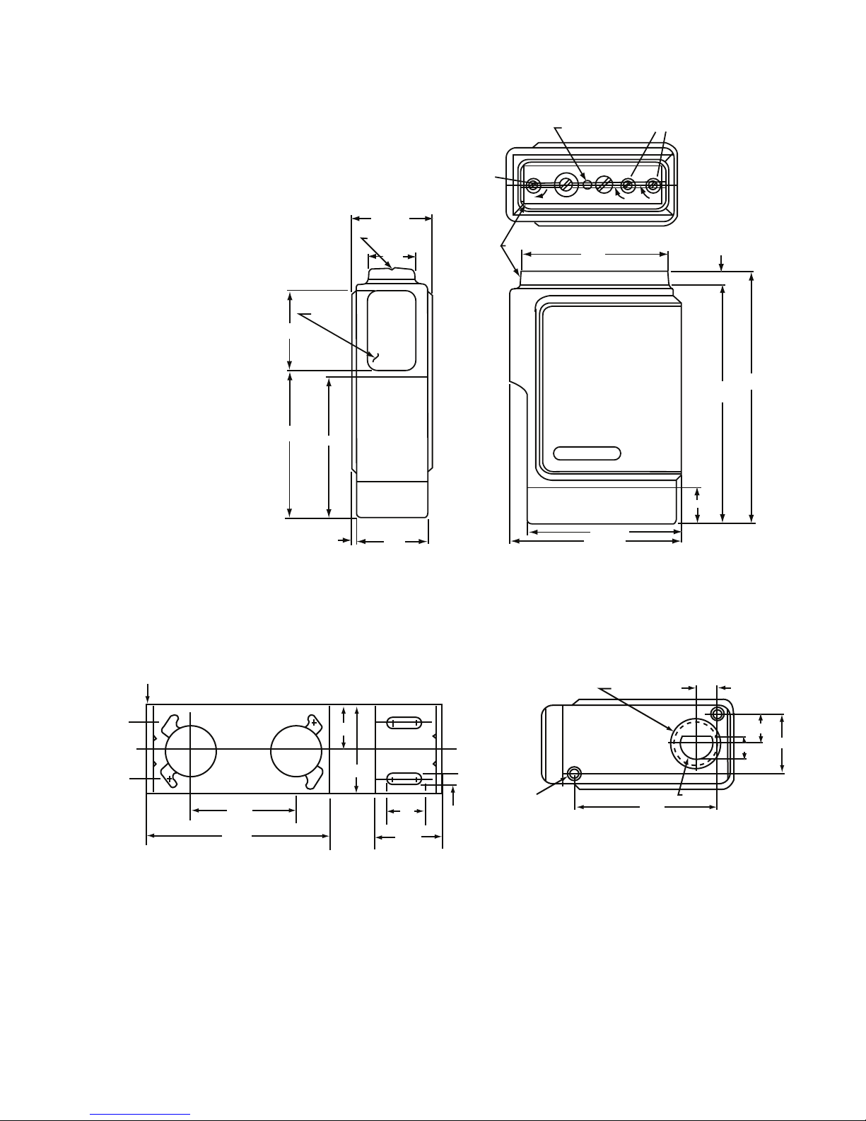
1.650 Max.
Sighting Aid
.930
Lens Area
1.50 - .92
1.50
= .010
2.81
= .010
2.68
.100 (Typ )
1.35
= .010
Sensitivity Adjustment
Sens.
LED Indicator
Timer Adjustments
Clear Dome
2.800
T1
T2
.260
4.63
= .010
4.905
Max.
.700
2.880 Max.
MCS - 50X-XX
3.185 Max.
WARNER
Photoscanner
12 Gauge Steel
1.645
3.25
.87
1.75
.80
1.40
.170
8-32 UNC-2B .312
Min. Thread
2 Holes
2.395
1/2-14 NPT .500
Min. Thread
.375
.410
.487
.975
.570 Ø Wiring Access Hole
Dimensions
Bracket
Figure 4
Warner Electric • 800-825-9050 819-0504
5
Page 6

Warranty
Warner Electric LLC warrants that it will repair or replace (whichever it deems advisable) any
product manufactured and sold by it which proves to be defective in material or workmanship
within a period of one (1) year from the date of original purchase for consumer, commercial or
industrial use.
This warranty extends only to the original purchaser and is not transferable or assignable without
Warner Electric LLC’s prior consent.
Warranty service can be obtained in the U.S.A. by returning any defective product, transportation
charges prepaid, to the appropriate Warner Electric LLC factory. Additional warranty information
may be obtained by writing the Customer Satisfaction Department, Warner Electric LLC, 449
Gardner Street, South Beloit, Illinois 61080, or by calling 815-389-3771.
A purchase receipt or other proof of original purchase will be required before warranty service is
rendered. If found defective under the terms of this warranty, repair or replacement will be made,
without charge, together with a refund for transportation costs. If found not to be defective, you
will be notified and, with your consent, the item will be repaired or replaced and returned to you
at your expense.
This warranty covers normal use and does not cover damage or defect which results from
alteration, accident, neglect, or improper installation, operation, or maintenance.
Some states do not allow limitation on how long an implied warranty lasts, so the above limitation
may not apply to you.
Warner Electric LLC’s obligation under this warranty is limited to the repair or replacement of the
defective product and in no event shall Warner Electric LLC be liable for consequential, indirect,
or incidental damages of any kind incurred by reason of the manufacture, sale or use of any
defective product. Warner Electric LLC neither assumes nor authorizes any other person to give
any other warranty or to assume any other obligation or liability on its behalf.
WITH RESPECT TO CONSUMER USE OF THE PRODUCT, ANY IMPLIED WARRANTIES WHICH
THE CONSUMER MAY HAVE ARE LIMITED IN DURATION TO ONE YEAR FROM THE DATE OF
ORIGINAL CONSUMER PURCHASE. WITH RESPECT TO COMMERCIAL AND INDUSTRIAL
USES OF THE PRODUCT, THE FOREGOING WARRANTY IS IN LIEU OF AND EXCLUDES ALL
OTHER WARRANTIES, WHETHER EXPRESSED OR IMPLIED BY OPERATION OF LAW OR
OTHERWISE, INCLUDING, BUT NOT LIMITED TO, ANY IMPLIED WARRANTIES OF
MERCHANTABILITY OR FITNESS.
Some states do not allow the exclusion or limitation of incidental or consequential damages, so
the above limitation or exclusion may not apply to you. This warranty gives you specific legal
rights and you may also have other rights which vary from state to state.
Changes in Dimensions and Specifications
All dimensions and specifications shown in Warner Electric catalogs are subject to change without
notice. Weights do not include weight of boxing for shipment. Certified prints will be furnished
without charge on request to Warner Electric.
Warner Electric LLC
31 Industrial Park Road • New Hartford, CT 06057
815-389-3771
www.warnerelectric.com
• Fax: 815-389-2582
P-241-100 819-0504 6/12 Printed in USA
 Loading...