

Aufstell- und Bedienungsanleitung
Pelletofen WP2-8 /WP2-8K
Installation and operating instructions
WP2-8 /WP2-8K Pellet Stove
Installation et instructions d’utilisation
Chaudière à pellet WP2-8 /WP2-8K
Istruzioni per uso e installazione
WP2-8 /WP2-8K Stufa a pellet
Kezelési- és használati útmutató
Pelletkandalló WP2-8 / WP2-8K

WP2-8_D 2 / 189
Vielen Dank, dass Sie sich für unser Produkt entschieden haben.
Bitte lesen Sie vor Aufstellung und Inbetriebnahme Ihres Gerätes die Anleitung! So vermeiden
Sie Schäden, die durch unsachgemäße Installation oder Handhabung hervorgerufen werden
können. Ihr Gerät wird Sie und die Umwelt lange mit einer optimalen Funktion verwöhnen.
Behagliche Wärme und viele gemütliche Stunden mit Ihrem Pelletofen wünscht Ihnen
Ihre WAMSLER Haus und Küchentechnik GmbH
INHALTSVERZEICHNIS
INHALTSVERZEICHNIS _____________________________________________________________________ 2
1. WICHTIGE ALLGEMEINE HINWEISE ______________________________________________________ 3
2. MAßZEICHNUNG, KABELPLAN___________________________________________________________ 4
3. SYSTEMANFORDERUNGEN_____________________________________________________________ 5
3.1. MINDESTLAUFZEITEN / AUSLEGUNG EXTERNER REGLER ______________________________ 5
3.2. RAUM- UND UMGEBUNGSTEMPERATUREN/-FEUCHTIGKEIT BEIM BETRIEB________________ 6
3.3. SCHORNSTEINANSCHLUSS ________________________________________________________ 6
3.4. VERBRENNUNGSLUFTVERSORGUNG________________________________________________ 6
3.5. PELLETQUALITÄT _________________________________________________________________ 6
3.6. REINIGUNG, WARTUNG UND PFLEGE ________________________________________________ 7
3.7. NETZSPANNUNG / SPANNUNGSVERSORGUNG________________________________________ 7
4. GERÄTE- UND FUNKTIONSBESCHREIBUNG _______________________________________________ 7
4.1. TECHNISCHE DATEN ______________________________________________________________ 7
4.2. LIEFERUMFANG __________________________________________________________________ 7
4.3. FUNKTIONSBESCHREIBUNG________________________________________________________ 7
4.4. ERSTINBETRIEBNAHME____________________________________________________________ 7
4.5. VOR DEM START / ZÜNDUNG _______________________________________________________ 7
4.6. BEDIENUNG UND HEIZBETRIEB _____________________________________________________ 7
4.7. TEMPERATUR MENÜ ______________________________________________________________ 7
4.8. BENUTZER MENÜ _________________________________________________________________ 7
4.9. ALLGEMEINE EINSTELLUNGEN _____________________________________________________ 7
4.10. EINSTELLUNGEN HAUPTMENÜ _____________________________________________________ 7
5. START_______________________________________________________________________________ 7
5.1. ERREICHUNG DES WERTES TEMPERATUR ___________________________________________ 7
5.2. EINSTELLUNG DER SCHALTUHR ____________________________________________________ 7
5.3. AUSSCHALTEN DES AUTOMATIKBETRIEBS ___________________________________________ 7
5.4. LEERUNG / AUFFÜLLUNG DES PELLETBEHÄLTER _____________________________________ 7
5.5. EIN-/AUSSCHALTEN DES ALARM- / „BEEP”-TONS ______________________________________ 7
6. STAND-BY (ABSCHALTUNG) ____________________________________________________________ 7
6.1. OFEN SCHALTET AUS _____________________________________________________________ 7
6.2. BESTÄTIGUNG ALARM_____________________________________________________________ 7
7. NETZSPANNUNG/ SPANNUNGSVERSORGUNG ____________________________________________ 7
7.1. SICHERUNGSTAUSCH _____________________________________________________________ 7
7.2. RÜCKSCHALTUNG DES SICHERHEITS-TEMPERATURBEGRENZERS (STB) _________________ 7
7.3. ANSCHLUSS DES EXTRENEN RAUMTHERMOSTATS: ___________________________________ 7
8. REINIGUNG UND PFLEGE ______________________________________________________________ 7
8.1. ÜBERPRÜFUNG UND REINIGUNG DES BRENNERTOPFES _______________________________ 7
8.2. REINIGEN DER SICHTSCHEIBE______________________________________________________ 7
8.3. REINIGUNG DER OBERFLÄCHEN ____________________________________________________ 7
8.4. REINIGUNG DER HEIZGASZÜGE ____________________________________________________ 7
8.5. KONTROLLE DER LUFTANSAUGUNG_________________________________________________ 7
8.6. KONTROLLE UND REINIGUNG DER ELEKTRISCHEN BAUTEILE___________________________ 7
8.7. ABSCHLUSS DER WARTUNGSARBEITEN, PROBELAUF _________________________________ 7
9. BRANDSCHUTZBESTIMMUNGEN ________________________________________________________ 7
9.1. EINRICHTUNGSGEGENSTÄNDE IM STRAHLUNGSBEREICH______________________________ 7
9.2. EINRICHTUNGSGEGENSTÄNDE AUßERHALB DES STRAHLUNGSBEREICHS________________ 7
9.3. BODEN UNTER UND VOR DEM OFEN_________________________________________________ 7
9.4. GEGENSTÄNDE IM BEREICH DER ZU- UND UMLUFTÖFFNUNGEN ________________________ 7
9.5. ABSTÄNDE ZUM VERBINDUNGSSTÜCK (RAUCHROHR) _________________________________ 7
9.6. SCHORNSTEINANSCHLUSS ________________________________________________________ 7
10. ZUGELASSENE BRENNSTOFFE _______________________________________________________ 7
11. LAGERUNG VON PELLETS____________________________________________________________ 7
12. KUNDENDIENST / ERSATZTEILE_______________________________________________________ 7
13. IHR FACHBETRIEB __________________________________________________________________ 7

WP2-8_D 3 / 189
1. WICHTIGE ALLGEMEINE HINWEISE
Bei Installation und Betrieb dieser Feuerstätte sind alle Anleitungen des Herstellers, die
europäischen Normen sowie die Vorschriften und Normen des Landes zu beachten, in
dem der Ofen aufgestellt und betrieben wird. Sie vermeiden so Fehlfunktionen und Bedien-
fehler.
Der Betreiber ist verpflichtet, sich vor Inbetriebnahme der Feuerstätte anhand der Anleitungen über die Besonderheiten der Feuerstätte und die geeigneten Brennstoffe zu informieren.
Der Pelletofen darf nur mit naturbelassenen Holzpellets nach EN-PLUS A1, DINplus oder
mind. Ö-Norm M7135 mit einem Ø von 6 mm betrieben werden. Stückholz oder andere
Brenn- und Abfallstoffe dürfen niemals verwendet werden.
In Europa gelten für Schornsteine die Europäische Norm EN 13384, für Abgasanlagen die
EN 15287 und für Verbindungsstücke die EN 1856-2.
In Deutschland gelten zusätzlich die Feuerungsverordnung (FeuVO), die Länderbauordnungen, die Elektro-/VDE-Richtlinien und die Fachregeln Heizungs- und Luftheizungsbau.
Ferner ist die 1. Bundes-Immissionsschutz-Verordnung (1. BImSchV) zu beachten. Des
Weiteren muss die Feuerstätte vor Inbetriebnahme vom zuständigen Schornsteinfegermeister
abgenommen werden. Das Abnahmeprotokoll dient als Betriebserlaubnis.
Der Betrieb des Gerätes in Kombination mit einer raumlufttechnischen Anlage (z.B. Lüftungsanlagen, Dunstabzugshauben, pneumatische Fördereinrichtungen etc.), sind die einschlägigen
technischen Regeln / Vorschriften (u.a. in Deutschland Kombination Lüftung – Feuerstätte
nur in Ausführung nach §4 FeuVO zulässig) zu beachten.
Die bestimmungsgemäße Verwendung wird nachfolgend erklärt.
Jede andere Verwendung gilt als nicht bestimmungsgemäß. Für hieraus resultierende Schäden
übernehmen wir keine Haftung. Zur bestimmungsgemäßen Verwendung gehört auch die Einhaltung der Bedienungs- und Montageanweisungen. Unerlaubte Eingriffe und Veränderungen
am Gerät führen zum Erlöschen der Gewährleistungs- und Garantieansprüche.
Arbeiten, wie insbesondere Installation, Montage, Erstinbetriebnahme und Servicearbeiten
sowie Reparaturen, dürfen nur durch einen ausgebildeten Fachbetrieb (Heizungs- oder Luftheizungsbau) durchgeführt werden. Bei unsachgemäßen Eingriffen erlöschen Gewährleistung
und Garantie. Der Anschluss und die Montage elektrischer Geräte dürfen nur durch eine Elekt-
rofachkraft erfolgen. Elektronische Bauteile wie u.a. Platine und Bedienfeld sind elektrostatisch
empfindlich.
Der Fachbetrieb hat im Rahmen der Endabnahme den Betreiber der Anlage immer in den Betrieb, die Reinigung und Wartung der Anlage eingehend und qualifiziert einzuweisen. Hierbei ist
besonders auf die Verwendung geeigneter Brennstoffe, die regelmäßig notwendige Reinigung
durch den Betreiber, die notwendige Wartung und die Sicherheitshinweise einzugehen. Insbesondere bei Nichtbeachtung der Anleitungen sowie der vorgeschriebenen Reinigung und Wartung erlöschen Gewährleistung und Garantie.
Vor Inbetriebnahme unbedingt prüfen, dass sämtliches Zubehör aus Brennraum und Asche-
lade entnommen worden ist und der Pelletbehälter frei von Rückständen ist.
Die Reinigung der Feuerstätte muss regelmäßig durch den Betreiber erfolgen.
Für die Wartung der Feuerstätte empfehlen wir den Abschluss eines Wartungsvertrages zwischen Fachhändler und Betreiber. Die regelmäßige Wartung kann auch durch den technisch
versierten und vom Fachbetrieb fundiert eingewiesenen Betreiber stattfinden.
WP2-8_D 4 / 189
Vor den Arbeiten Netzstecker ziehen! Der Netzstecker bzw. die zugehörige Steckdose muss
jederzeit leicht zugänglich sein. Der Betrieb des Gerätes mit beschädigtem Netzkabel ist verboten. Wenn das Netzkabel beschädigt wird, muss dieses sofort durch einen qualifizierten Fachhandwerker ersetzt werden, um Gefährdungen zu vermeiden.
Netzstecker des Ofens nicht im Betrieb ziehen! Ofen vorher ausschalten, Gebläsenachlauf (Ausbrand) vollständig abwarten.
Mit richtigem Betrieb / Bedienung und guter Pflege / Wartung erhöhen Sie die Wertstabilität und Lebensdauer Ihres Gerätes. Sie sparen wertvolle Ressourcen und schonen unsere Umwelt und Ihren Geldbeutel.
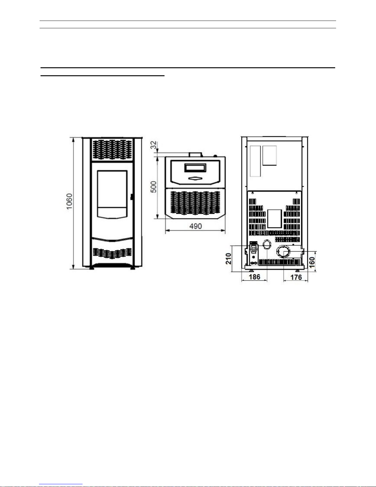
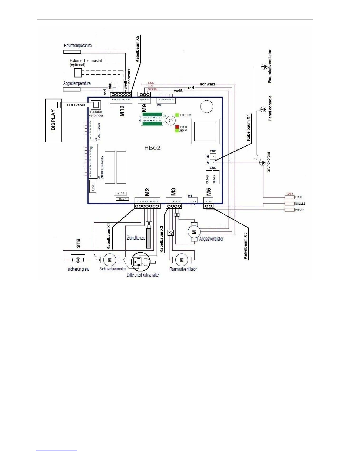
2. MAßZEICHNUNG, KABELPLAN
WP2-8_D 5 / 189
3. SYSTEMANFORDERUNGEN
Unsere Geräte werden immer mit anderen bautechnischen Einrichtungen / Produkten verbunden und stellen daher, wie alle technischen Produkte, für den störungsfreien Betrieb bestimmte
Systemanforderungen. Nachfolgend sollen einige besonders wichtige Anforderungen explizit
genannt werden. Diese Aufstellung erhebt keinen Anspruch auf Vollständigkeit. Bitte beachten
Sie alle Anleitungen / Angaben, wie bereits einleitend bemerkt. Im Vorfeld sollte immer eine
fundierte Anlagenplanung über einen Fachbetrieb erfolgen, damit die einzelnen Systemkomponenten auch aufeinander abgestimmt sind und die gewünschte Gesamtlösung erreicht wird.
3.1. MINDESTLAUFZEITEN / AUSLEGUNG EXTERNER REGLER
Bei Pellets handelt es sich um einen festen Brennstoff, der zum Zünden brennstoffbedingt mehr
Zeit benötigt als ein flüssiger oder gasförmiger Brennstoff. Der Zündvorgang bis zur ersten
Flamme benötigt bereits einige Minuten nach dem Start, wenn das Anheizprogramm beendet
ist, steht die volle Leistung des Gerätes zur Verfügung. Wird das Gerät ausgeschaltet dauert es
ebenfalls - im Gegensatz zu Öl- oder Gasfeuerungen - einige Minuten, bis alle Pellets abgebrannt sind und die Flamme erlischt. Im Gerät ist daher eine Gebläsenachlaufzeit (Display Anzeige „INFO“) von einigen Minuten einprogrammiert, die abgelaufen sein sollte, bevor das Gerät
neu gestartet wird.

WP2-8_D 6 / 189
Bei Ansteuerung des Gerätes mit externem Regler sollte daher auf eine Mindestlaufzeit geachtet werden. Zu diesem Zweck ist in der Steuerung eine Nachlaufzeit einprogrammiert (einstellen
über das Menü „INFO“). Nach Erreichen der Solltemperatur am Regler bleibt der Ofen noch für
die Dauer der Nachlaufzeit in Betrieb, bevor der Abbrandmodus beginnt (Diese Funktion soll
optional über das Menü eingestellt werden)
3.2. RAUM- UND UMGEBUNGSTEMPERATUREN/-FEUCHTIGKEIT BEIM BETRIEB
Alle Geräte sind ausschließlich ausgelegt zum Betrieb in Wohnräumen mit normaler Luftfeuchtigkeit und Wohnraumtemperaturen von +5°C bis +30°C (Umgebungstemperaturen bei Betrieb).
Die Öfen sind nicht spritzwassergeschützt und dürfen nicht in Nassräumen aufgestellt werden.
Aufgrund der Betriebs- und Flammgeräusche der Öfen können wir die Aufstellung in Schlafund Ruheräumen nicht empfehlen. Während des Betriebes sind deshalb Arbeitsgeräusche wie
das Fallen von Pellets sowie Flamm-/Strömungs- und Antriebsmotorengeräusche hörbar. Bei
Temperaturen < 5 °C (z.B. in Ferienhäusern) sind bestimmte Mindesteinstellungen am Ofen
vorzunehmen und es müssen zusätzlich geeignete Frostschutzeinrichtungen (z.B. elektrische
Heizwächter) vorgesehen werden. Bei Temperaturen > 25 °C können im Betrieb Sicherheitseinrichtungen wirksam werden. Bitte beachten Sie hierzu die jeweiligen Hinweise zum Heizbetrieb
in den Geräteanleitungen.
3.3. SCHORNSTEINANSCHLUSS
Der Anschluss an einen für feste Brennstoffe geeigneten Schornstein ist zwingend vorgeschrieben. Das Verbindungsstück muss aus Metall ausgeführt sein. Ihr zuständiger Be-
zirksschornsteinfegermeister berät Sie gerne. Eine Mehrfachbelegung (gemeinsamer Betrieb an
einem Schornstein von Pelletgeräten) ist in Deutschland die DIN 18896 zu beachten. Der Förderdruck (Schornsteinzug = Unterdruck) muss zwischen minimal 6 Pa und maximal 15 Pa liegen (Soll 12 Pa). Vor der Installation muss immer eine Schornsteinberechnung nach EN 13384
erfolgen und muss bis mind. 400°C belastbar sein. Der Schornstein sorgt gerade bei Spannungsausfall für den sicheren Abtransport der Rauchgase aus dem Gerät und übernimmt somit
eine wichtige Sicherheitsfunktion. Bei zu hohem Schornsteinzug empfehlen wir den Einbau eines Zugbegrenzers. Siehe Kapitel 10.6
3.4. VERBRENNUNGSLUFTVERSORGUNG
Die Geräte arbeiten raumluftabhängig. Eine ausreichende Verbrennungsluftversorgung ist
zwingend notwendig. Unterdrücke im Aufstellraum sind nicht zulässig. Daher sind bei der Kombination mit raumlufttechnischen Anlagen (z.B. Lüftungsanlagen, Dunstabzugshauben, pneumatische Fördereinrichtungen etc.) die einschlägigen technischen Regeln / Vorschriften der
Feuerungsverordnung §4 (FeuVo für Deutschland) maßgeblich.
Ist der Ofen in raumluftabhängiger Betriebsweise mit einer raumlufttechnischen Anlage gegenseitig zu verriegeln oder eine Lüftungsanlage einzubauen, die eine Zulassung für Festbrennstofffeuerungen hat, muss dem Aufstellraum die notwendige Verbrennungsluft (ca. 25-30 m³/h)
zuführt werden.
3.5. PELLETQUALITÄT
Nach der 1. Bundes-Immissionsschutz-Verordnung (1. BImSchV) sind in Deutschland nur naturbelassene Holzpellets zugelassen. Die Pelletqualität beeinflusst maßgeblich die Reinigungsund Wartungszyklen.
Wir definieren alle unsere Angaben und Prüfwerte auf Pelletqualitäten mit 0,25% Aschegehalt,
einer Schüttdichte von 650 kg/m³ und einem Heizwert Hu > 4,9 kWh/kg. Damit entsprechen im
Energiegehalt 500 Liter Heizöl ungefähr 1000 kg solcher Holzpellets. Als Lagervolumen benötigen 1000 kg dieser Pellets ca. 1,54 m³ Volumen. Abweichungen von den o.g. Vorgabewerten
sind aufgrund der Toleranzfelder der einschlägigen Normen für Pellets (u.a. ENplus-A1, DINPLUS, DIN 51731 oder Ö-Norm M7135) u.a. bei Aschegehalt, Schüttdichte, Zusammensetzung

WP2-8_D 7 / 189
und Größe/Geometrie nicht zu vermeiden und führen zwangsweise zu Abweichungen bei verschiedenen Angaben.
So bedeutet z.B. eine Verdoppelung des Aschegehalts von 0,25% auf 0,5% auch eine Verdoppelung der Reinigungs- und Wartungshäufigkeit. Nach DIN 51731 sind leider auch Pellets mit
bis zu 1,5% Aschegehalt am Markt zulässig und verfügbar. Mit dieser schlechteren Qualität
werden die Reinigungs-/ Wartungsintervalle um den Faktor 6 verkürzt! Für unsere Pelletöfen ist
der Aschegehalt der Pellets daher die mit Abstand wichtigste Größe. Wir geben u.a. deshalb
nur Pellets, die nach ENplus-A1, DIN PLUS oder Ö-Norm 7135 geprüft sind und einen Aschegehalt < 0,7% haben, für die Verwendung in unseren Geräten frei.
Handelsübliche gute Markenpellets haben heute durchgängig einen Aschegehalt von < 0,3%.
Fragen Sie Ihren Pelletlieferanten nach dem Aschegehalt. Je geringer, desto besser. Durch den
Zusatz zugelassener natürlicher Bindemittel in den Pellets kann, trotz Prüfung nach den o.g.
Normen, ein Verschlacken der Pelletasche im Brennertopf stattfinden. Wir empfehlen daher den
Verzicht auf silikathaltige Bindemittel wie Kartoffelstärke und Verwendung z.B. von Weizenstärke. Fragen Sie auch hierzu Ihren Pelletlieferanten. Bei hoher Schüttdichte und spezieller Geometrie bzw. hohem Heizwert der Pellets, können interne Sicherheitseinrichtungen das Gerät in
der Leistung zeitweise absenken, bis die Sollwerte wieder erreicht sind. Dies stellt keinen Mangel dar. Das Gerät moduliert dann.
Bei Pellets mit extrem geringer Schüttdichte oder zu geringem Heizwert können die angegebenen Nennleistungen und Leistungsbereiche geringfügig unterschritten werden. Dies stellt ebenfalls keinen Mangel dar, sondern liegt in der Natur von riesel- und schüttfähigen Brennstoffen.
Durch den Fachbetrieb kann der Ofen über die Steuerung in bestimmten Bereichen auf verschiedene Schüttdichten und Pelletqualitäten eingestellt werden. Stückholz oder andere Brennund Abfallstoffe dürfen niemals verwendet werden. Wird der Ofen mit nicht zugelassenen
Brennstoffen betrieben, erlöschen sämtliche Gewährleistungs- und Garantieansprüche und es
können gefährliche Betriebszustände entstehen. Unternehmen Sie keine Experimente.
Ein Pelletdurchmesser zwischen 5 und 7 mm ist zulässig. Die Durchschnittslänge der Pellets
sollte 30mm nicht überschreiten. Pellets mit zu hohem Staubgehalt (> 5%) sollten ebenfalls
nicht verwendet werden.
3.6. REINIGUNG, WARTUNG UND PFLEGE
Im Gegensatz zu flüssigen oder gasförmigen Brennstoffen, fällt bei festen Brennstoffen immer
Asche und Ruß an. Zwar liegt die Verbrennungsgüte und der Bedienkomfort der Pelletöfen Geräte weit über dem Niveau vergleichbarer Stückholzfeuerungen, dennoch ist in regelmäßigen
kurzen Abständen eine Reinigung der Brennerschale (durch den Betreiber) und in größeren
Zeitabständen eine Wartung/Inspektion notwendig, um die Geräte von Ruß und Asche zu befreien. Ohne diese Maßnahmen können Störungen auftreten, für die wir keine Haftung übernehmen können. Regelmäßige Pflege, Reinigung und Wartung erhalten auch die Effizienz Ihrer
Anlage, da gerade Ruß ein hervorragender Isolator ist und so die Wärmeabgabe / den Wirkungsgrad erheblich reduzieren kann.
Reinigungsintervall: tägliche optische Kontrolle des Brennertopfs mit bedarfsabhängiger manueller Reinigung.
Wartungsintervall: 1.500 kg Pelletverbrauch (bei 0,25% Aschegehalt). Bitte beachten Sie die
Kapitel 3.5 und 8 in dieser Anleitung.
3.7. NETZSPANNUNG / SPANNUNGSVERSORGUNG
230 V AC / 50 Hz (zulässiger Schwankungsbereich 195-255 V)
Bitte beachten Sie die Kapitel 7 in dieser Anleitung.

WP2-8_D 8 / 189
4. GERÄTE- UND FUNKTIONSBESCHREIBUNG
4.1. TECHNISCHE DATEN
WP2-8A WP2-8KA
Max. Nennwärmeleistung
Min. Nennwärmeleistung
Max. Brennstoffverbrauch ca.
Min. Brennstoffverbrauch ca.
Wirkungsgrad (NWL)
Wirkungsgrad (Teillast)
Schonsteinzug (min.)
Schonsteinzug (max.)
Inhalt Pellettank ca.
Stromanschluss
Frequenz
Max. Leistungsaufnahme
Durchmesser Abgasstutzen
Gewicht ca.
kW
kW
kg/h
kg/h
%
%
Pa
Pa
kg (Liter)
V
Hz
VA
mm
kg
7,5
2,5
1,9
0,6
90,5
95
6
12
21 (32)
230
50
350
80
96
6,5
2,5
1,9
0,6
90
96
6
12
21 (32)
230
50
300
80
94
Wichtiger Hinweis:
Bitte notieren Sie direkt nach der Inbetriebnahme hier die Fertigungsnummer Ihres Ofens vom
Typenschild und bewahren Sie die Rechnung auf. Im Gewährleistungsfall oder für spätere
Ersatzteillieferungen benötigen wir immer die Artikelnummer und die Fertigungsnummer
des Gerätes, damit Sie die passenden Ersatzteile erhalten. Ohne Angabe der Fertigungsnum-
mer und des Kaufdatums können wir keine Gewährleistung anerkennen und Fehllieferungen
nicht ausschließen. Bewahren Sie alle Dokumente die mit Ihrem Gerät geliefert worden sind
dauerhaft auf, Sie unterstützen so etwaige Kundendienstleistungen oder Nachbesitzer des Gerätes.
Fertigungs-Nr. Ihres Gerätes unbedingt nach dem Kauf hier eintragen: _______________
4.2. LIEFERUMFANG
Im Lieferumfang ist folgendes Zubehör enthalten:
• Hitzeschutzhandschuh, Hilfswerkzeug zum Öffnen der Tür, Anleitungen
4.3. FUNKTIONSBESCHREIBUNG
Ein WAMSLER Pelletofen ist ein spezielles Heizgerät nur für den häuslichen Gebrauch und nur
für die Verfeuerung von Ø 6 mm Holzpellets nach ENplus A1 geeignet. Das Gerät erzeugt im
Heizbetrieb Warmluft, die an den Raum abgegeben wird. Für den Heizbetrieb den Ofen einfach
einschalten und die gewünschte Leistungsstufe wählen. Bei Einsatz eines externen Reglers
kann der Pelletofen auch automatisch ein- und ausgeschaltet bzw. die Leistungsstufe automatisch moduliert werden. Die Holzpellets werden vollautomatisch in die Brennerschale gefördert
und über eine elektrische Zündung angezündet.
Entsprechend der gewählten Heizleistung fördert die gesteuerte Förderschnecke selbsttätig die
richtige Brennstoffmenge nach. Die für die Verbrennung notwendige Luft strömt kontrolliert zur
Brennerschale. In der Brennkammer und den nach geschalteten Heizgaszügen brennen die
Gase aus und geben ihre Energie an die Umgebung ab.
Am Ende der Heizgaszüge befindet sich ein Absauggebläse, das abgestimmt auf BrennstoffMenge und Verbrennungsluft, die Rauchgase sicher zum Schornstein führt.
WP2-8_D 9 / 189
In regelmäßigen Abständen muss die Brennerschale durch den Betreiber von Asche und
Schlacke gereinigt werden. Ebenso ist die Sichtscheibe vom Aschebelag zu reinigen. Zusätzlich
ist eine regelmäßige Wartung der Heizgaszüge notwendig, die durch einen Fachbetrieb durchgeführt werden sollte.
Festbrennstoffe erzeugen naturgemäß Ruß, ein Verschmutzen der Sichtscheibe ist dadurch niemals völlig ausgeschlossen und stellt keinen Mangel dar
Die Geräte sind für die Aufstellung im Wohnraum konzipiert, geprüft und zugelassen. Für die
Verbrennung muss ausreichend Sauerstoff nachströmen können. Daher ist eine Kombination
mit raumlufttechnischen Anlagen, wie insbesondere Dunstabzugshaube, Lüftungsanlage oder
pneumatischer Förderanlage für Holzpellets, nur unter bestimmten Auflagen zulässig. Fragen
Sie dazu Ihren Bezirksschornsteinfegermeister oder Ihren ausführenden Fachbetrieb.
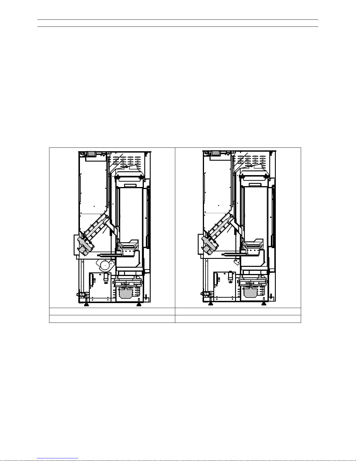
Funktionsschnitt
WP2-8A WP2-8KA
mit Konvektionsgebläse ohne Konvektionsgebläse
4.4. ERSTINBETRIEBNAHME
Wichtige Hinweise:
• Feuerraumtür immer, auch im kalten Zustand, geschlossen halten.
• Im Heizbetrieb können alle Oberflächen und besonders die Sichtscheibe sowie der Griff und
Bedieneinrichtungen sehr heiß werden. Wärend des Heizbetriebes sollten Kinder und Jugendliche, ältere Mänschen sowie Tiere auf diese Gefahren hingewiesen und von der Feuerungsstätte fern gehalten werden. Verwenden Sie zur Bedienung den beigelegten Schutzhandschuh oder das Hilfswerkzeug. Kinder und Jugendliche unter 16 Jahren dürfen den
Ofen ohne Aufsicht Erziehungsberechtigter nicht bedienen.
• Auch die Verkleidungen können im Dauerbetrieb heiß werden. Benutzen Sie den mitgelieferten Hitzeschutzhandschuh.

WP2-8_D 10 / 189
• Alle Stahl- und Gussteile des Ofens wurden im Werk mit hochhitzebeständigem Lack beschichtet und eingebrannt. Beim ersten Anheizen des neuen Pelletofen trocknet der Lack
nach, dabei kann Geruch und Rauch entstehen! Hierzu bitte folgende Ratschläge beachten:
o Den Raum gut durchlüften, damit die freiwerdenden Dämpfe abziehen können.
o Während der Aushärtezeit ist der Lack noch weich. Lackierte Flächen möglichst nicht
berühren, um eine Beschädigung der Lackoberfläche auszuschließen.
o Das Aushärten des Lackes ist nach einiger Betriebszeit mit großer Heizleistung be-
endet.
Erst nachdem das Gerät gemäß Montageanleitung komplett installiert worden ist, dürfen Pellets
in den Vorratsbehälter gefüllt werden. Vorratsbehälter mit mindestens 5 kg Holzpellets füllen.
Im Pellettank, Brennraum oder Brennertopf dürfen sich keine Gegenstände mehr befinden.
Vorratsbehälter auffüllen
Behälterdeckel öffnen. Die Naht des Pelletsacks auftrennen und Sack mit der Öffnung nach
unten bis zum Schutzgitter in den Vorratsbehälter hinein stülpen und langsam entleeren. Nach
dem Füllen den Behälterdeckel schließen und während des Betriebes stets geschlossen halten.
Unser Tipp: Schütten Sie die Pellets langsam und nicht aus großer Höhe nach, damit wenig
Staub aufgewirbelt wird. Pellets lassen sich auch mit einem Eimer oder ähnlichem in den Vorratsbehälter füllen.
Hinweis VORSICHT beim Einfüllen! Pellet Sack nicht mit dem heißen Ofen in Berührung bringen. Pellets, die den Weg in den Vorratsbehälter nicht gefunden haben, sofort entfernen!
Achtung: Keine Fremdkörper in den Vorratsbehälter einwerfen; evtl. Schäden werden nicht im
Rahmen der Garantie / Gewährleistung behoben.
Einschaltvorgang
Bei der Erstinbetriebnahme ist die Förderschnecke noch völlig leer. Beim ersten Einschalten
fallen daher erst nach ca. 10 Minuten die ersten Pellets in die Brennerschale und die Zündung
ist bereits wieder ausgeschaltet. Gleiches gilt, wenn der Vorratsbehälter zu spät aufgefüllt wurde und völlig leer gelaufen ist.
Vorgehensweise in beiden Fällen, damit das Gerät sicher zündet:
• Gerät über I/O-Taste einschalten und warten, bis das Anheizprogramm abgelaufen ist und
die ersten Pellets in den Brennertopf fallen.
• Gerät über I/O-Taste sofort wieder ausschalten und nach 5 Sekunden wieder neu starten.
Das Anheizprogramm läuft nochmals ab und sobald die ersten Pellets in die Brennerschale
fallen zündet das Gerät. Vorgang bei Bedarf nochmals wiederholen
Unser Tipp:
Wenn der Vorratsbehälter völlig leer gelaufen war und in der Förderschnecke keine Pellets
mehr sind, können Sie die Zeit bis wieder Pellets in den Brennertopf fallen und das Gerät zündet dadurch verkürzen, dass Sie eine Handvoll Pellets bis zur ersten Lochreihe in den Brennertopf geben.
Achtung: Auf keinen Fall den Brennertopf ganz füllen, eine Fehlfunktion wäre die Folge!
4.5. VOR DEM START / ZÜNDUNG
Hinweis: Der Zündvorgang bis zur ersten sichtbaren Flamme kann (je nach Reinigungszustand
der Brennerschale) bis zu 10 Minuten dauern und startet nach jedem Neueinschalten oder
Spannungsausfall neu.
WP2-8_D 11 / 189
• Feuerraumtür öffnen. Prüfen, ob Brennerschale und Brennraum frei von Verunreinigungen
oder Pellets sind und bei Bedarf Brennerschale von Pellets/Asche/Schlacke reinigen.
• Türe schließen.
• Gerät durch Drücken der I/O-Taste einschalten. Pellets werden in der Brennerschale geför-
dert. Das Anzünden erfolgt automatisch über die im Gerät eingebaute Zündung. Nach
spätestens 5-10 Minuten beginnen die Pellets zu brennen.
• Schlägt die Zündung fehl (unverbrannte Pellets in der Brennerschale), prüfen Sie bitte zu-
erst die Brennerschale auf Verunreinigungen (alle Luftlöcher müssen frei sein) und ob der
Vorratsbehälter aufgefüllt wurde. Eventuell müssen die Pellets auch erst durch die Schnecke
hindurch laufen, dies dauert ca. 10 Minuten, falls es sich um eine Erstinbetriebnahme handelt oder der Vorratsbehälter komplett leer gelaufen war. Reinigen Sie die Brennerschale
vollständig, bevor Sie wieder starten. Bei einem Fehlstart Brennerschale vollständig
leeren und unverbrannte Pellets sowie Asche entsorgen. Niemals unverbrannte Pellets aus der Brennerschale wieder in den Vorratsbehälter geben oder gar in der Brennerschale anzünden.
• Brandgefahr durch Glutreste und/oder Überhitzung!
4.6. BEDIENUNG UND HEIZBETRIEB
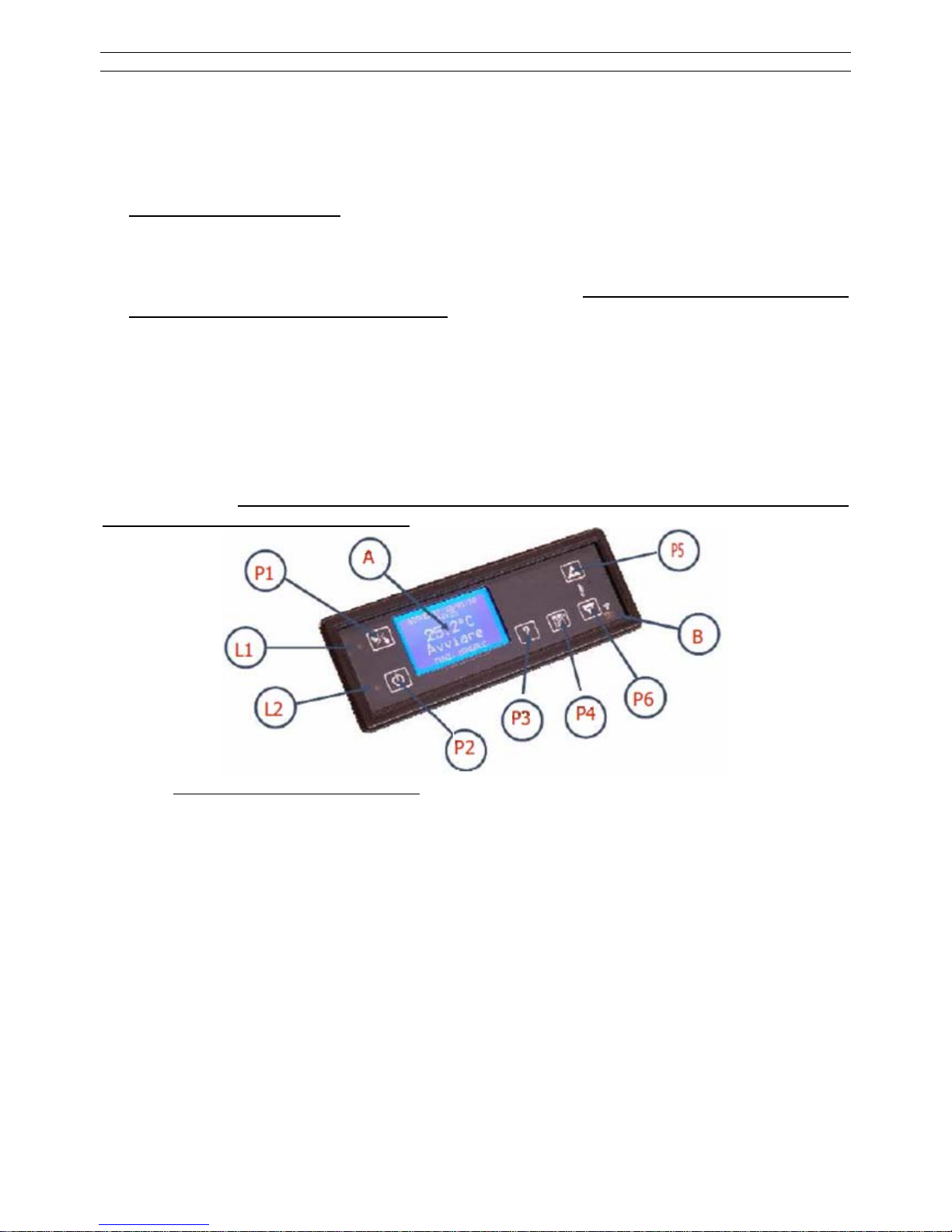
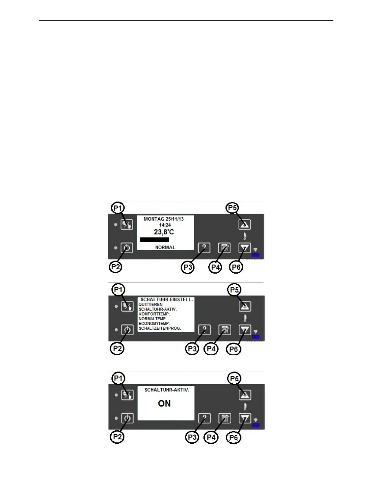
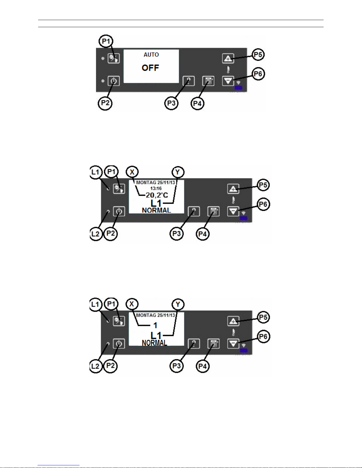
Für die Bedienung des Gerätes stehen verschiedene Tasten zur Verfügung, die durch Anzeigen
ergänzt werden. In der Regel benötigen Sie zum Betrieb des Gerätes ausschließlich die
I/O-Taste und die Tasten „+“ und „-“.
P1 Zugang zum Zeitschaltuhrmenü
P2 ON / OFF - Taste
P3 HILFE - Taste
P4 SET - Taste - Zugriff auf das Menü - "Parameter ändern"
P5 „+“- Taste - Erhöhung
P6 „-“ - Taste - Verringerung
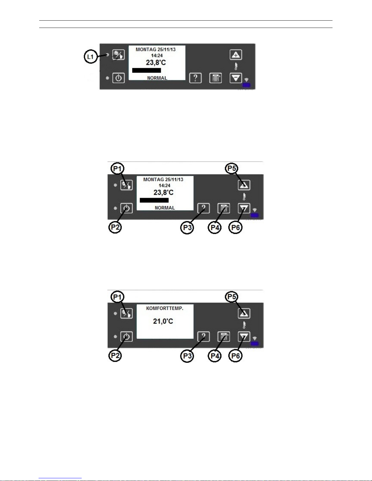
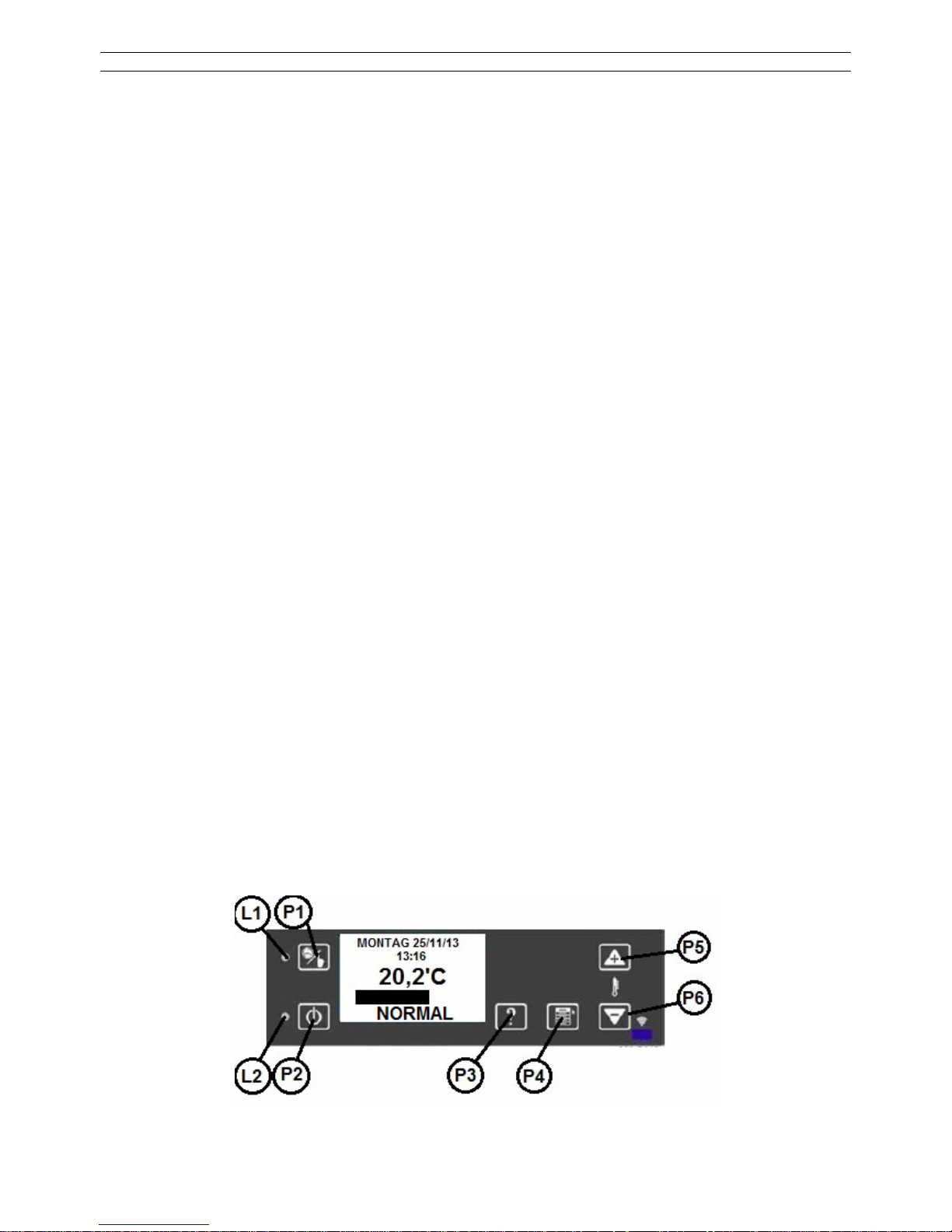
L1 LED - Thermostat - an (ON) - aus (OFF)
L2 LED - Betrieb - an (auch wenn nicht aktiv) - aus (System ist AUS)
A Anzeige / Display
B Red-ray Funkfernbedienung (nicht aktiv)
Kontrasteinstellung Display
Nur in der Hauptansicht möglich. Die Tasten P5 zur Erhöhung und P6 zur Verringerung drücken.
Display-Beleuchtung
Nur in der Hauptansicht möglich. Die Tasten P3 gleichzeitig mit der Taste P5 oder P6 zur Erhöhung oder Verringerung der Beleuchtungsstärke drücken.
WP2-8_D 12 / 189
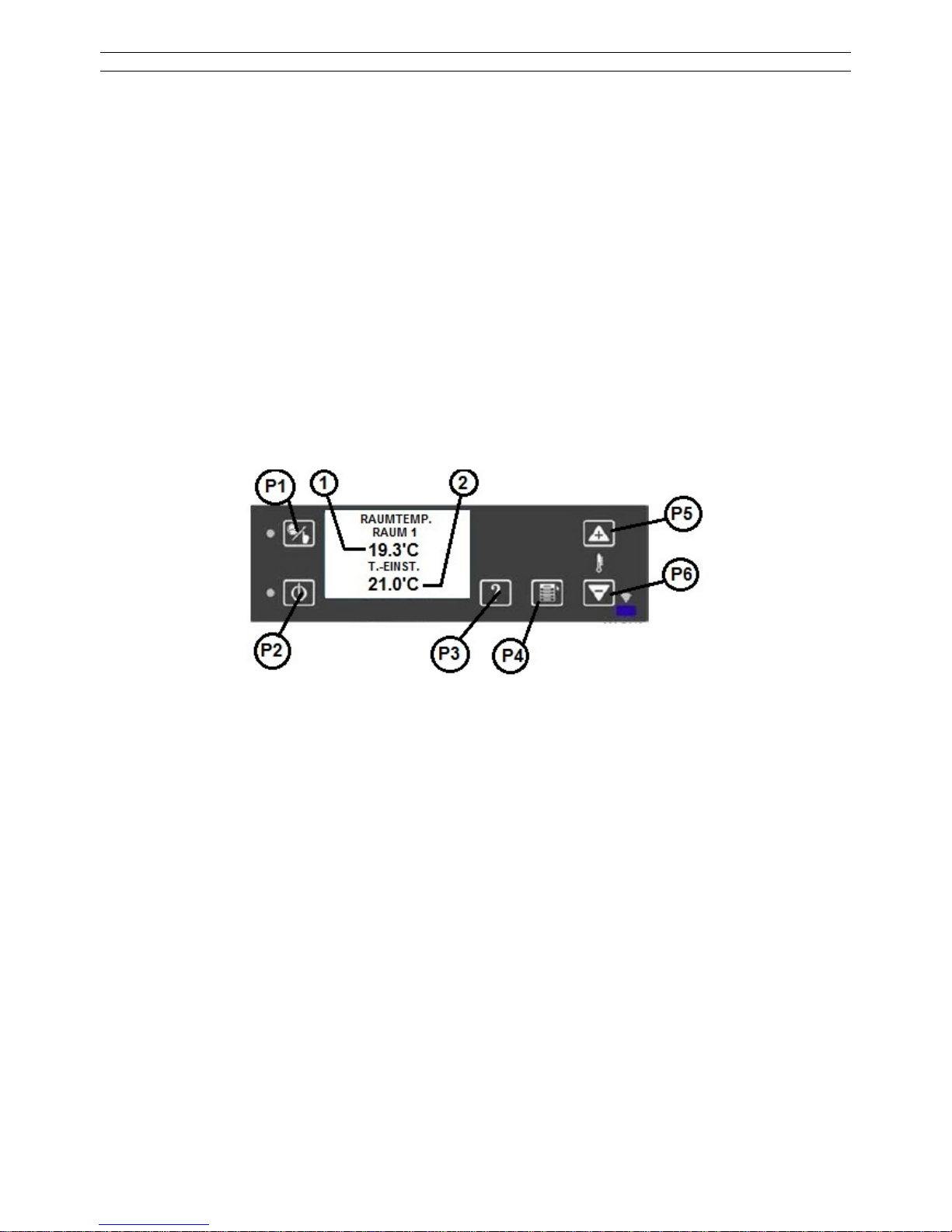
Änderung der Temperatur
Drücken der Taste P4 bis im Menü die Raumtemperatur angezeigt wird. Änderung der Werte
mit den Tasten P5 oder P6 (Diese Menüeinstellung ist nicht verfügbar, wenn ein externes
Thermostat aktiviert wurde).
Der Zugang zur Schaltuhr Einstellung
Drücken Sie die Taste P1 für ca. 5 sec..
HILFE –Taste (P3). Die Informationen werden durch Drücken der Taste P3 für ca. 10 sec.
sichtbar gemacht.
Für die ON / OFF Funktion halten Sie die Taste P2 für ca. 3 Sekunden gedrückt.
Informationen über den Ofen abrufen
Drücken Sie die Tasten P1 und P2 gleichzeitig. Es wird der Status des Gerätes angezeigt.
Drücken Sie die Taste P4 (MENÜ / SET) für ca. 5 sec.
Mit den Tasten P5/P6 kann das auszuwählende Menü markiert werden
Auswahl über die Taste P4 (SET). Änderungen erfolgen über die Tasten P5 und P6.
4.7. TEMPERATUR MENÜ
Mit der Taste 2X P4 (SET / Menü) können Sie die Menü-Funktionen ändern.
1. Aktuelle Raumtemperatur
2. Eingestellte Raumtemperatur
Mit den Tasten P5 / P6 erhöhen oder verringern Sie die eingegebene Temperatur. Mit der Taste
P4 bestätigen Sie die Temperatur.
Durch nochmaliges drücken der Taste P4 kommen Sie wieder in die Hauptansicht zurück.

WP2-8_D 13 / 189
4.8. BENUTZER MENÜ
Menüstruktur:
Durch längeres drücken (ca. 3 Sekunden) der Taste P4 kommen Sie ins Benutzermenü.
QUITTIEREN: Zurück zum Hauptmenü
VORFUELLEN: PELLETZUFUHR Funktion
(Einstellung nur im ausgeschalteten Zustand möglich,
es sind zwei Einstellungen möglich)
OFENSTATUS: Information über aktuellen Status
PELLETSORTE-EINST.: Einstellung der Pelletqualität
RAUMGEBLÄSE-EINST.: Einstellung des Raumluftgebläses innerhalb der zulässigen
Grenze
HAUPTMENUE: Einstellung von Datum/ Uhrzeit/ Display/ Standby/ Sprache
WP2-8_D 14 / 189
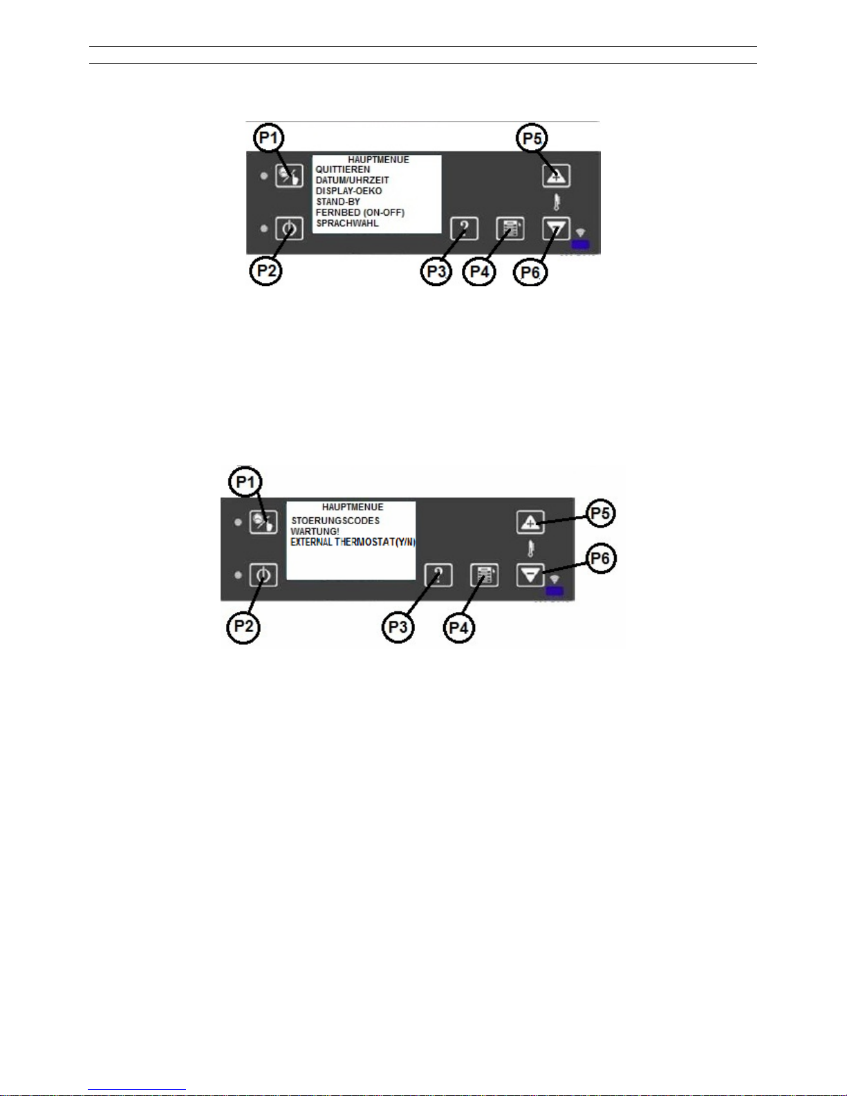
4.9. ALLGEMEINE EINSTELLUNGEN
Das Hauptmenü ist in zwei Seiten aufgeteilt, die mit den Tasten P5/P6 ausgewählt werden können:
Erste Menüseite:
QUITTIEREN: Zurück zum Hauptmenü
DATUM/UHRZEIT: Einstellung Uhrzeit / Datum
DISPLAY DEKO: Aktivierung / Deaktivierung der Display-Leuchtdauer
STAND-BY: Aktivierung / Deaktivierung der Standby – Funktion (Abschaltung)
FERNBED. (J/N): Aktivierung / Deaktivierung der Fernbedienung (nicht im Lieferum-
fang)
SPRACHWAHL Einstellung der Sprache (DE/IT/HU)
Zweite Menüseite:
STOERUNGSCODES: Anzeige der registrierten Fehlermeldungen (ALARMS), welche in der
log Datei gespeichert wurden
WARTUNG: Information über die Wartung
EXT. THERMOSTAT: Aktivierung/ Deaktivierung des Ext. thermostat
WP2-8_D 15 / 189
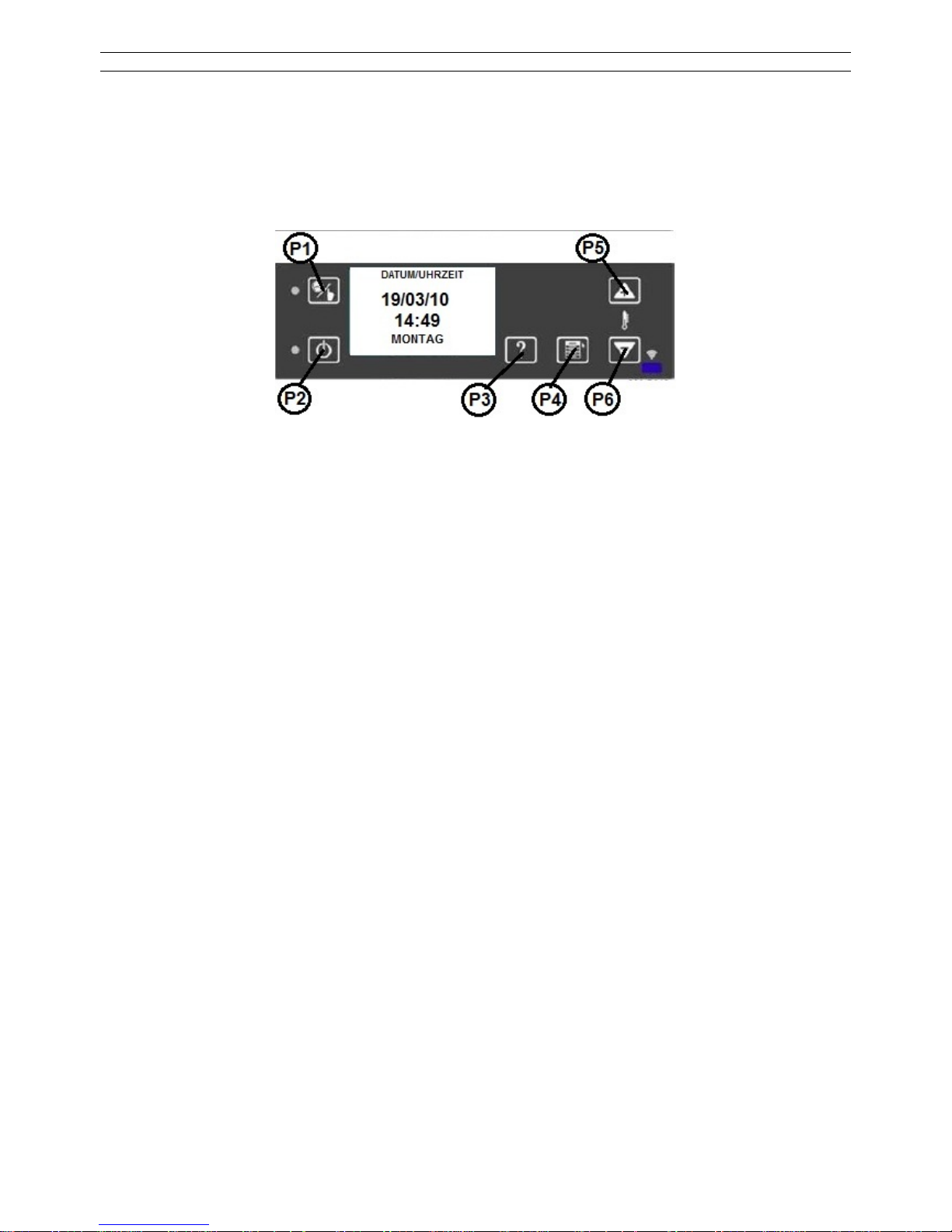
4.10. EINSTELLUNGEN HAUPTMENÜ
DATUM / UHRZEIT
Durch Anwahl und kurzes drücken der Taste P4 wechseln Sie in dieses Menü.
Einstellung der Werte erfolgt über die Tasten P5 und P6. Eine Wochentag Einstellung ist nicht
nötig.
Durch längeres drücken der Taste P4 kommen Sie wieder zurück ins Menü.
DISPLAY „OEKO“
Die Taste P4 aktiviert / deaktiviert den Anzeigemodus, nachdem nach 300 sec. keine Tasten
mehr gedrückt wurde. Einstellung der Werte erfolgt über die Tasten P5 und P6.
STANDBY
Durch Anwahl und kurzes drücken der Taste P4 wechseln Sie in dieses Menü.
Einstellung der Werte erfolgt über die Tasten P5 und P6, Bestätigung und Verlassen über kurzes betätigen der Taste P4.
FERNBEDINUNG (J/N)
Durch Anwahl und kurzes drücken der Taste P4 wechseln Sie in dieses Menü.
Einstellung der Werte erfolgt über die Tasten P5 und P6, Bestätigung und Verlassen über kurzes betätigen der Taste P4.
Zum Zeitpunkt der Drucklegung nicht erhältlich.
SPRACHWAHL
Durch Anwahl und kurzes drücken der Taste P4 wechseln Sie in dieses Menü.
Einstellung der Werte erfolgt über die Tasten P5 und P6, Bestätigung und Verlassen über kurzes betätigen der Taste P4.
5. START
Niederdrücken des Druckknopfes P2 (ON/OFF) für etwa 2-3 Sekunden.
Das Programm prüft automatisch nachfolgende Bedingungen:
ANFÄNGLICHE REINIGUNGSBEDINGUNG
Betrieb des Abzugsventilators für 5 Sekunden.
HEIZBEDINGUNGEN
Die Zündung schaltet mit dem Abgasventilator ein. Dauer: 180 Sekunden.
VORLASTBEDINGUNG
Die Schnecke schaltet zusammen mit dem Abgasventilator für 60 Sekunden ein.
STAND-BY BEDINGUNG
Der Schneckeninterval wird für 120 Sekunden abgebrochen (Parameter PA04), damit die Pellets leichter entzünden.
EINSCHALTBEDINGUNG
Der Abgasventilator und die Schnecke sind für 1500 Sekunden aktiv.
Der Übergang zur nächsten Phase erfolgt nur, wenn die Abgastemperatur über den minimal
zugelassenen Wert von 50 °C ansteigt.
WP2-8_D 16 / 189
Kommt diese Phase innerhalb der zugelassenen Zeitdauer von 1500 Sekunden nicht zustande,
geht der Pelletofen wegen des Ausbleibens der Zündung in den Alarmstatus.
BEDINGUNG DER STABILISIERUNG
Nach Erreichen der min. Temperatur von 50°C schaltet die Zündung aus. Die vorgeschriebene
Stabilität der Flamme und die Erhöhung der Temperatur mit mindestens 3°C/Minute müssen
abgewartet werden. Die Zeitdauer dieses Zustands beträgt ca. 180 Sekunden.
Kommt diese Bedingung nicht zustande, schaltet der Pelletofen auf Grundlage der unregelmäßigen Flamme in den Alarmstatus.
BETRIEBSBEDINGUNG
Der Ofen schaltet das Raumluftgebläse bei einer Abgastemperatur von 90°C ein.
BETRIEB
Der Pelletofen geht in Betrieb.
TIMER (Zeiteinstellung)
Mit der Zeiteinstellungsfunktion kann man das Gerät für eine Woche vorprogrammieren.
(Ofen Ein, Aus / Einstellungen der Temperatur: Komfort, Normal, Eco)
Für das Zeiteinstellungsmenü drücken Sie P1 für 3 sec.
Aktivieren sie den Zeiteinstellung. „SCHALTUHR-AKTIV.“ (P4, P5, P6 Taste)
WP2-8_D 17 / 189
Die L1 LED leuchtet
5.1. ERREICHUNG DES WERTES TEMPERATUR
Der Pelletofen erhält kontinuierlich die gewünschte Temperatur und garantiert dem Benutzer die
besten Bedingungen ohne große Leistungsschwankungen, mit einem minimalen Energieaufwand nach der Erreichung des Wertes.
Die Leistung wird in einem Streifendiagramm angezeigt. Dieses Diagramm zeigt gleichzeitig
auch die Raumtemperatur.
EINSTELLUNGEN DER TEMPERATUR
Das Menü ermöglicht die Einstellung von drei Temperaturen: COMFORT, NORMAL,
ECONOMY.
Zu jeder Einstellung steht ein Programmfenster zur Verfügung.
Das unten angegebene Beispiel gilt für die Einstellung COMFORT:
Mit den Tasten P5/P6 kann der Temperaturbereich erhöht oder verringert werden. Zur Speicherung Taste P4 lang niederdrücken.
WP2-8_D 18 / 189
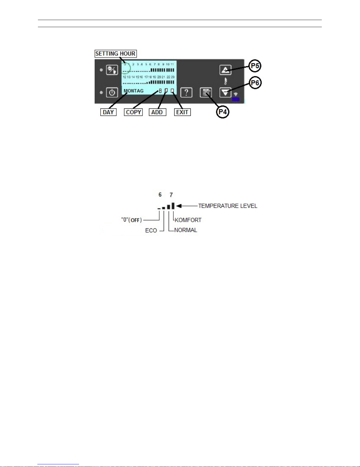
5.2. EINSTELLUNG DER SCHALTUHR
Siehe untere Abbildung:
Die Abbildung zeigt jeden Tag der Woche. Das Feld DAY (Tag) ist in 24 Perioden aufgeteilt,
jede Periode dauert 1 Stunde (1, 2,….24) und ist wiederum in zwei Halbstunden aufgeteilt.
Auswahl der Funktionen und der Stundenbereiche
Durch das Drücken der Tasten P5 und P6 kann in beiden Richtungen unter den Symbolen
(Stunden, Tage der Woche und den Symbolen der Programmierung „copy, add, exit“) gewählt
werden.
Hier können die erwünschten Bereiche, zum Beispiel die Zeit 7:00 (siehe Abbildung) ausge-
wählt werden.
TEMPERATURNIVEAU
Mit der Taste P4 (SET) können Sie durch kontinuierliches Drücken, die schwarzen Balken auf
die gewünschte Höhe eingestellen (0 „AUS“, ECO, NORMAL, KOMFORT).
Im Beispiel ist der Pelletofen um 6:00 aus (OFF), um 6:30 schaltet er im Modus ECO ein, um
7:00 im Leistungsniveau NORMAL und um 7:30 arbeitet dieser im KOMFORT Modus.
Die Stundenreihen können mit den Tasten P5 und P6 eingestellt werden.
Änderung der Wochentage
Mit den Tasten P5 und P6 können die Wochentage eingestellt werden. Zur Einstellung der Wochentage wird die Taste P4 (SET) gedrückt. Die Tage der Woche erscheinen nacheinander.
Nach der Auswahl des Tages können die Stundenreihen mit den Tasten P5 und P6 der oben
angegebenen Reihenfolge entsprechend eingestellt werden.
Zu jedem Tag können mehrere Ein- und Ausschaltungen und Temperaturwerte vorprogrammiert werden.
Die folgende Seite beschreibt das Kopieren der Einstellungen eines Tages zu einem anderen
Tag.
Kopieren der Einstellungen eines Wochentages:
Mit der Taste P5 (vorwärts) oder P6 (zurück) kann die Stundenreihe eingestellt werden, dann
zum Symbol copy gehen und die Taste P4 (SET) kopieren.
Mit der Taste P6 (zurück) zurück zum Wochentag gehen und durch drücken der Taste P4 den
Tag auswählen, zu dem die Werte kopiert werden sollen.
Mit der Taste P5 (vorwärts) zum Symbol Add gehen und die Taste P4 (SET) drücken.
WP2-8_D 19 / 189
Das Verfahren kann zu jeden Wochentag, zu dem Einstellungen kopiert werden, wiederholt
werden.
Zum Verlassen der Kopierfunktion mit den Taste P5 (vorwärts) oder P6 (zurück) zum Symbol
exit gehen und wiederum die Tate P4 (SET) drücken.
Im Beispiel Abbildung:
Um 6:30 schaltet der Ofen im Niveau 3 (KOMFORT) ein.
Um 12:00 schaltet der Ofen aus und bleibt in diesem Zustand bis 17:30.
Um 17:30 schaltet der Ofen im Niveau 1 (ECO) ein.
Um 18:00 verändert der Ofen die Leistung und schaltet auf das Niveau 2 (NORMAL) über.
Um 18:30 verändert der Ofen die Leistung und schaltet auf das Niveau 3 (COMFORT) über.
Die Programmierung ist wirkungslos, wenn sich der Ofen im OFF Zustand befindet.
(LED ist in Stellung ON).
ACHTUNG! Das Programmierungsfeld kann eingeschaltet werden, auch wenn der Ofen ausgeschaltet (OFF) ist, und dann kann über das Programmierungsfeld gesteuert werden.
5.3. AUSSCHALTEN DES AUTOMATIKBETRIEBS
In der Grundeinstellung funktioniert der Pelletofen im AUTOMATIKBETRIEB mit Leistungsregelung.
Dies bedeutet, dass die Heizleistung des Ofens zum Erreichen der eingestellten Temperatur
von der Steuereinheit automatisch eingestellt wird. In diesem Fall wird aufgrund der Differenz
der Raumtemperatur und der eingestellten Temperatur, welche die optimale Leistung ist, geregelt.
Wenn der AUTOMATIKBETRIEB AUSGESCHALTET ist, kann der Benutzer zwischen fünf definierten Leistungsstufen wählen:
L1 etwa 2,0 - 2,3 kW
L2 etwa 4,0 - 4,3 kW
L3 etwa 6,5 - 6,9 kW
L4 etwa 7,0 - 7,2 kW
L5 etwa 7,2 - 7,5 kW
Der Pelletofen funktioniert zu der ausgewählten Leistungsstufe, bis die Raumtemperatur den
eingestellten Wert erreicht.
Nach dem Erreichen der Temperatur schaltet der Pelletofen auf eine kleinere Leistungsstufe.
Zum Ausschalten des AUTOMATIKBETRIEBS sind folgende Aktivitäten auszuführen.
Drücken Sie die Taste P4 .
WP2-8_D 20 / 189
Mit Hilfe der Schaltflächen P5-P6 stellen Sie das Gerät von ON(EIN) auf OFF(AUS).
Zum Verlassen drücken Sie 2-mal die Schaltfläche P4.
Danach erscheint im Hauptmenü die aktuell eingestellte Leistungsstufe:
Zum Beispiel:
X: die aktuelle Raumtemperatur ist 20,2’C
Y: Der Ofen ist in der Leistungsstufe L1 eingestellt
Einstellung der Leistungsstufe:
Zum einstellen der Leistungsstufe drücken Sie die Schaltfläche P4.
Auf dem Display erscheint folgende Information:
X: Eingestellte Leistungsstufe
Y: Aktuelle Leistungsstufe
Zur Erhöhung der Leistungsstufe drücken Sie die Taste P5, zur Senkung die Taste P6.
Nach einer gewissen Zeit schaltet der Pelletofen auf die eingestellte Stufe.
Einstellung der Raumtemperatur:
Durch kurzes drücken der Taste P4 gelangen Sie zur Raumtemperatureinstellung:
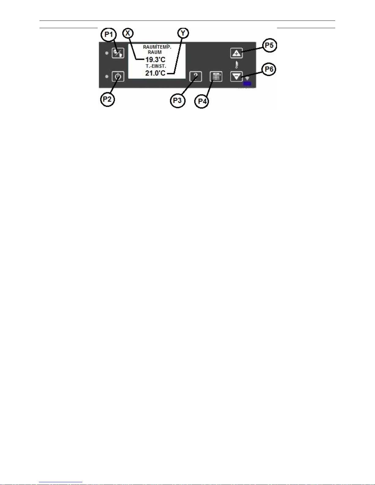
WP2-8_D 21 / 189
X: Aktuelle Raumtemperatur
Y: Eingestellte Raumtemperatur
Die Raumtemperatur kann mit den Schaltflächen P5 und P6 eingestellt werden.
Zurück zur Hauptseite gelangen Sie durch Drücken der Schaltfläche P4.
5.4. LEERUNG / AUFFÜLLUNG DES PELLETBEHÄLTER
Der Pelletverbrauch des Ofens hängt von der eingestellten Leistungsstufe ab. Überprüfen Sie
mindestens einmal täglich, ob die Menge ausreichend ist.
Sollte sich der Pelletbehälter völlig geleert haben, erscheint auf dem Display die Fehlermeldung
„Pelletmangel”. In diesem Fall bestätigen Sie die Meldung mit P2 und füllen den Behälter wie-
der auf. Das Gerät können Sie mit der Taste P2 neu starten.
Hinweis!
Beim ersten Start, oder wenn sich der Behälter völlig entleert hat, braucht der Pelletofen zur
Neuzündung mehr Zeit, da sich in diesem Fall das Zufuhrsystem völlig auffüllen muss.
Es kann auch vorkommen, dass der Startvorgang zu wiederholen ist. In diesem Fall erscheint
auf dem Display „1. Versuch“.
Die Meldung macht darauf aufmerksam, dass der Start mit langem Drücken von P2 2-mal zu
wiederholen ist.
Wenn Sie den Ofen innerhalb von 15 Minuten nicht neu starten, erscheint die Fehlermeldung
F01 (erfolglose Zündung).
WICHTIGER HINWEIS!
Vergewissern Sie sich immer vor dem Start, ob der Brennertopf völlig leer ist. Der Brennertopf
darf weder Asche noch unverbrannte Pellets enthalten, da dies zu einem mangelhaften Betrieb
führen kann.
Die regelmäßige Kontrolle des Brennertopfes ist auch im Laufe eines programmierten Betriebes
wichtig. Wir schlagen vor, die Kontrollen in den programmierten Betriebspausen durchzuführen.
5.5. EIN-/AUSSCHALTEN DES ALARM- / „BEEP”-TONS
Grundeinstellung des Alarm- / „Beep”-Tons ist OFF-AUS.
Die Einstellung geschieht wie folgt:
Achtung! Der Ofen muss im ausgeschalteten Zustand sein.
1. Drücken Sie die Schaltfläche P3 auf dem Hauptbildschirm 3 Sec.
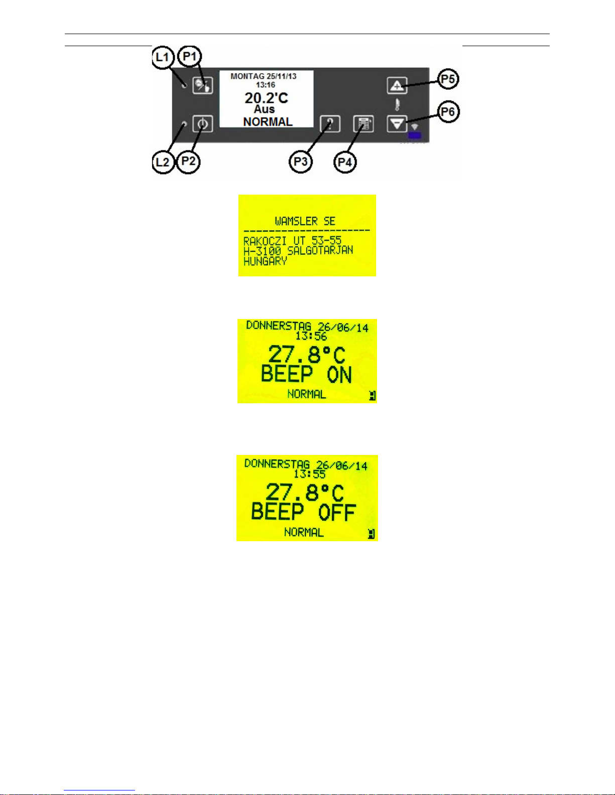
WP2-8_D 22 / 189
2. Danach erscheint auf dem Display folgender Text:
3. Jetzt drücken Sie sofort die Schaltfläche P1. Auf dem Display ist nun das „BEEP” ON
(EIN) zu sehen:
Zum Ausschalten von „BEEP” wiederholen Sie die drei vorgenannten Schritte.
Danach ist auf dem Display zu sehen:
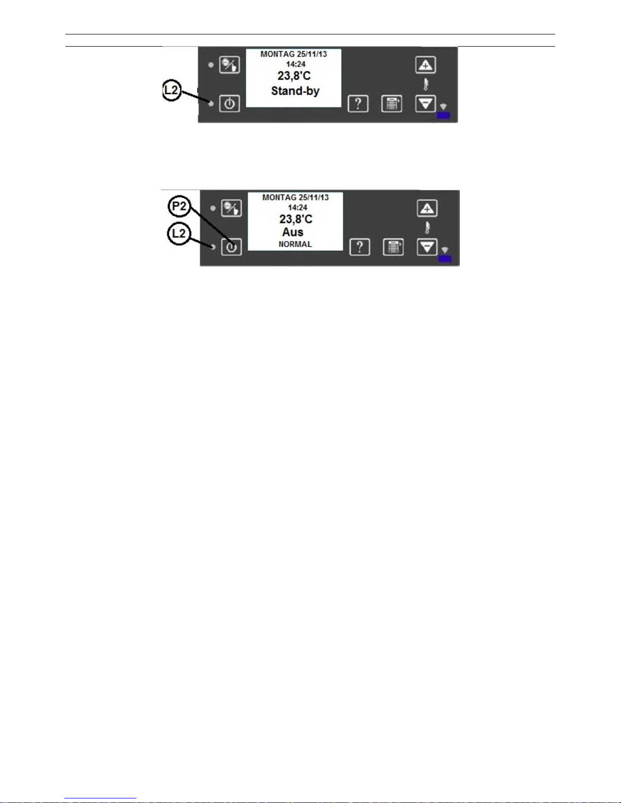
6. STAND-BY (ABSCHALTUNG)
Nach Aktivierung des STAND-BY Modus und Erreichen der eingestellten Raumtemperatur (*)
schaltet der Ofen aus und beharrt in diesem Modus.
Innerhalb von 5 Minuten, nachdem die Raumtemperatur mit 2°C überschritten wird, schaltet der
Ofen in die Status STAND-BY (Bereitschaft) über.
Der Zustand STAND-BY wird ebenfalls mit dem aufleuchten der LED Lampe (L2) angezeigt.
In diesem Betriebszustand ist der Pelletofen immer noch in Betrieb und schaltet erst wieder aktiv ein, wenn die eingestellte Raumtemperatur um 2°C abgesunken ist und sich mindestens 10
Minuten in diesem Zustand befindet.
WP2-8_D 23 / 189
(*) wenn die Raumtemperatur aktiv ist
6.1. OFEN SCHALTET AUS
Sie können jederzeit das Gerät mit der Taste P2 (ON/OFF) ausschalten.
Wenn der Ofen in den Ausschaltungszustand über geht, blinkt die grüne LED Lampe L2 bis zur
vollen Abschaltung (OFF).
AUSSCHALTUNGSZUSTÄNDE
Nach dem Drücken der Taste P2 (ON/OFF) zum Ausschalten, geht der Ofen in den Zustand
SWITCH OFF, danach in den Abkühlzustand über.
Der Abgasventilator schaltet in die höchste Stufe, damit alle Pellets im Brennertopf verbrennen.
Der Übergang zum nächsten Zustand ist erst möglich, wenn die Abgastemperatur den Grenzwert von 70°C nicht übersteigt.
ABKÜHLUNG
Der Abgasventilator bleibt für 300 Sekunden eingeschaltet.
Nach dieser Zeit schaltet der Abgasventilator vollkommen aus (LED L2 ist OFF).

WP2-8_D 24 / 189
STROMAUSFALL
Bei einem Stromausfall von kürzer als 10 sec. setzt der Ofen seinen Betrieb einfach wieder fort.
Steht der Ofen im STAND-BY Modus wird dieser Zustand wieder hergestellt.
In allen anderen Zuständen schaltet sich der Ofen bei einem Stromausfall aus.
DRUCKABFALL (Druckdose)
Wenn ein unvorhersehbarer Druckabfall das Gerät erkennt und die Druckdose in einer Verbrennungsphase öffnet, schaltet der Ofen in den Zustand “DEPRESSION“ über, wonach das
Abgasgebläse seine Drehzahl solange erhöht, bis die Druckdose wieder schließen kann.
Bleibt der Kontakt der Druckdose länger als 20 Sekunden offen, schaltet der Ofen wegen des
Druckabfalls in den Alarmzustand über.
ALARM
Der Ofen gibt nach einer Fehlermeldung mit einer Verzögerung von 60 sec. Alarm.
Wenn binnen der vorgeschriebenen Zeitdauer die Alarmmeldung nicht zurückgesetzt wird,
schaltet der Ofen in den Alarmzustand über und schaltet sich aus. Der Abgasventilator arbeitet
dann mit der höchsten Drehzahl.
Jeder Alarmzustand, ausgenommen “keine Pellets”, wird im Speicher der Alarmhistorie registriert.
F01
keine Zündung Pellettank leer, schlechte Qualität vom Brennstoff
F02
keine Stabilisierung zu geringe Wärmeentwicklung nach dem Start
F03
zu geringe Abgastemperatur Pellettank leer, schlechte Qualität vom Brennstoff
F04
Raumtemperaturfehler
F05
Platinentemperatur zu hoch Gerät abkühlen lassen
F06
zu große Druckdifferenz zwischen Abgas und Raum Schornstein / Abgasrohr / Gerät verschmutzt
F07
StB, interne Temperatur zu hoch Gerät abkühlen lassen
F08
Abgasventilator
Schornstein / Abgasrohr / Gerät verschmutzt
Ventilator defekt
F10
Schneckenmotor arbeitet seit mehr als 40 Sekunden
F11
Druckschalterkontakt bei der erstmaligen Prüfung
geschlossen
Schornsteinzug zu hoch, Druckdose defekt
F13
Überhöhte Abgastemperatur
6.2. BESTÄTIGUNG ALARM
Durch kurzes drücken der Taste P2 (EIN / AUS) wird der Alarm bestätigt und durch längerem
drücken der Taste P2 (ON/OFF) wird der Ofen abgeschaltet.
Ist das Gerät nicht zu stoppen, müssen Sie möglicherweise Hilfe zu Rate ziehen.
Netzstecker des Ofens nicht im Betrieb ziehen! Ofen vorher ausschalten, Gebläsenachlauf (Ausbrand) vollständig abwarten.
7. NETZSPANNUNG/ SPANNUNGSVERSORGUNG
Das Gerät darf nur aus einer Netzsteckdose mit Schutzerdung betrieben werden.
230 V AC/50 Hz (zugelassene Schwankung: 195-255 V)
Nur das im Zubehör befindliche Netzanschlusskabel verwenden!
Es ist darauf zu achten, dass das Kabel nicht mit den heißen Oberflächen des Ofens (Abgasrohr, usw.) in Berührung kommt.
Bei Beschädigung, schadhaften Stellen des Anschlusskabels ist dieses sofort zu tauschen. Zur Erneuerung eines Ersatzkabels nehmen Sie bitte den Kontakt mit unserem
Kundendienst auf.
WP2-8_D 25 / 189
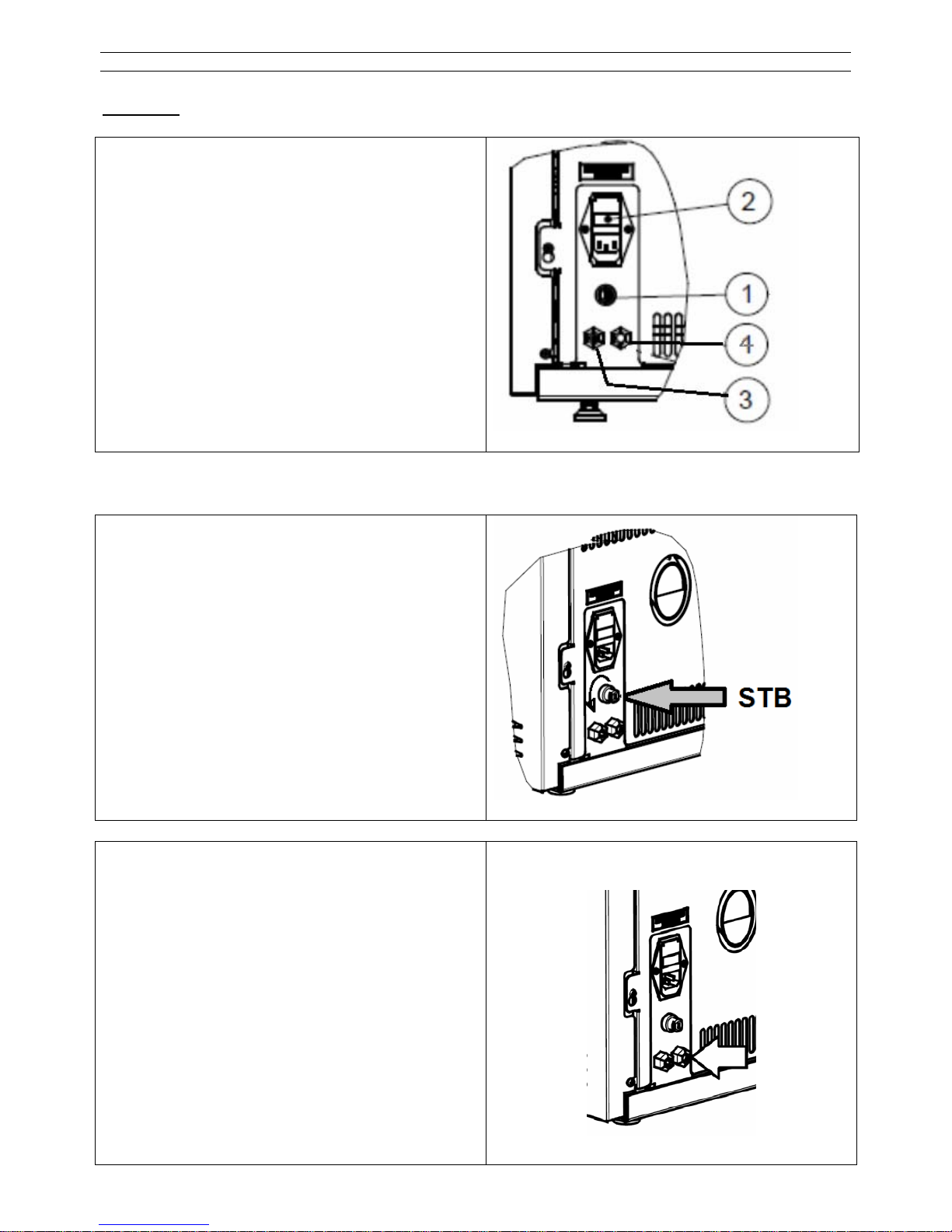
7.1. SICHERUNGSTAUSCH
Achtung! Austausch darf nur von einem Fachmann ausgeführt werden!
1. STB Sicherheits-Temperaturschalter
2. Hauptschalter, Netzanschluss-Steckdose,
Sicherungshalter
3. Temperaturfühler für Raumtemperatur
4. Externe Thermostat Eingabe
Der Sicherungstausch darf nur an einem span-
nungslosen Ofen ausgeführt werden!
Schalten Sie zuerst den Hauptschalter ab und
trennen Sie das Anschlusskabel vom Netz.
Das vom Netzanschluss trennbare Sicherungshaltefach (2) enthält 2 Stk. 2,5A-Sicherungen.
Bei Tausch können nur Sicherungen des folgenden Typs verwendet werden!
Typ: 250V/2,5A (F) 5*20mm
7.2. RÜCKSCHALTUNG DES SICHERHEITS-TEMPERATURBEGRENZERS (STB)
Der Sicherheitstemperaturbegrenzer (STB) ist
eine vorgeschriebene Sicherheitseinrichtung,
die das Gerät bei Überhitzung ausschaltet.
Fehlerkode: F07
Rückschaltung ist mit der Hand auszuführen.
Schutzkappe abdrehen und Knopf eindrücken.
Kann der Schalter nicht zurückgedrückt werden,
dann ist die Temperatur des Gerätes noch zu
hoch. Abkühlung abwarten.
7.3. ANSCHLUSS DES EXTRENEN RAUMTHERMOSTATS:
Diese Aktion kann nur an einem Gerät
durchgeführt werden, das nicht unter Strom
steht!
Führen Sie das Kabel des Externen RaumThermostats durch die Stopfbuchse wie in der
Abbildung ersichtlich.
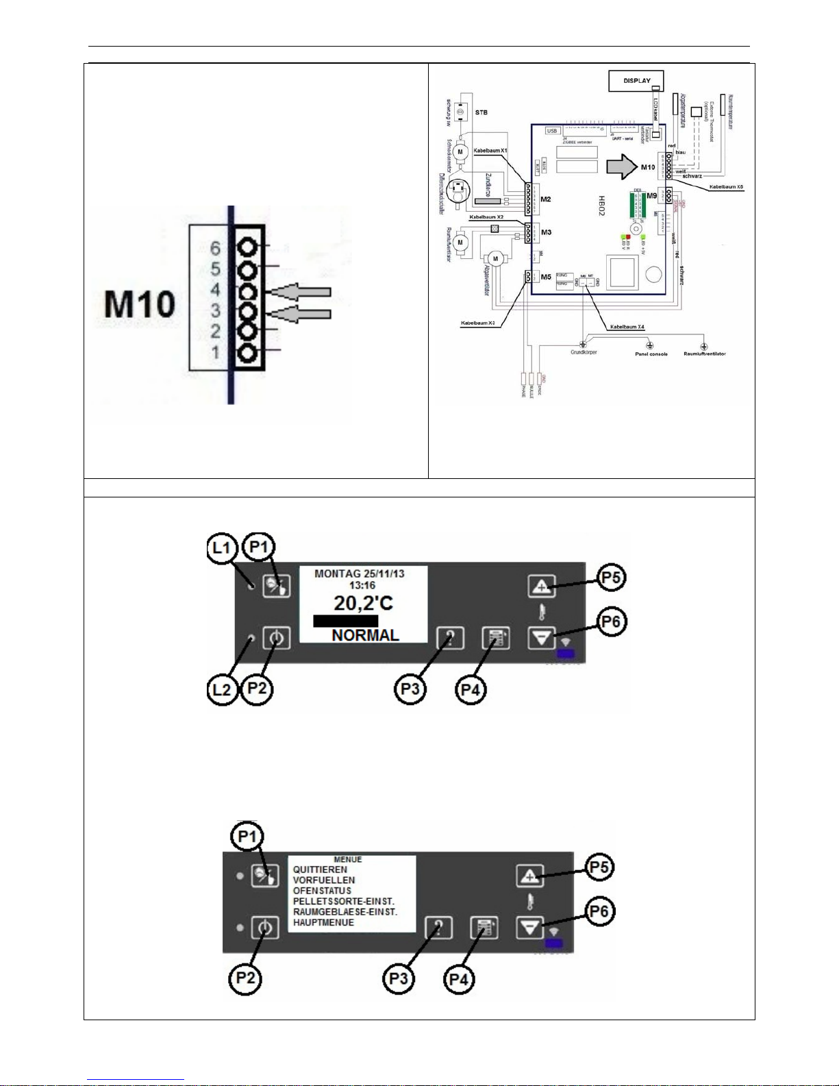
WP2-8_D 26 / 189
Die zwei Kabel des Thermostats schließen Sie
am markierten Anschluss M10, Punkte 3,4 an.
Einstellung des externen Thermostates in der Software:
Drücken Sie die Taste P4 3Sec. lang
Nach dem Drücken der Taste P4 erscheint folgendes Menü:
Mit der Taste P5/P6 wählen Sie das „HAUPTMENÜ“ aus und drücken nochmals die Taste P4.

WP2-8_D 27 / 189
Mit den Tasten P5/P6 gehen Sie zur 2. Seite und wählen das Untermenü „EXTERNAL THERMOSTAT“ aus. Drücken Sie die Schaltfläche P4 um ins Menü zu gelangen.
Mit Hilfe der Schaltflächen P5/P6 stellen Sie das Gerät von ON auf OFF.
Exit : P4
8. REINIGUNG UND PFLEGE
Bei der Verbrennung von Festbrennstoffen fällt immer Asche und Ruß an. Deshalb ist eine
regelmäßige Reinigung durch den Betreiber für den störungsfreien Betrieb zwingend
notwendig.
Achtung / Gefahr:
Geräte, die nicht entsprechend unseren Angaben gereinigt werden, dürfen nicht betrieben werden. Bei Nichtbeachtung erlöschen sämtliche Gewährleistungsansprüche.
Die Anzahl der notwendigen Reinigungen des Brennertopfes ist ausschließlich abhängig
vom Aschegehalt der Pellets und kann nicht durch Einstellungen am Gerät verändert
werden, da Asche einfach die nicht brennbaren Bestandteile der Pellets sind!
Wir empfehlen daher, nur Holzpellets mit einem Aschegehalt < 0,5% zu verwenden.
Für die Wartung benötigen Sie Fachkenntnisse, weshalb wir die Durchführung der Wartung
durch einen Fachbetrieb dringend empfehlen.
Achtung / Warnung:
Brand-, Kurzschluss- und Lebensgefahr !
Der Betrieb der Geräte ist nur mit allen ordnungsgemäß montierten Verkleidungsteilen zulässig, da sonst die Zulassung der Geräte sowie Gewährleistung und Ga-
rantie erlöschen, weil die Gefahr besteht, Spannungsführende oder heiße Teile zu
berühren.
Ziehen Sie vor Beginn der Arbeiten den Netzstecker
WP2-8_D 28 / 189
und stecken Sie den Netzstecker für Probelauf erst wieder ein, wenn alle
Verkleidungsteile wieder vollständig und fachgerecht montiert worden sind.
Achtung! Beginnen Sie mit der Reinigung erst wenn der Ofen völlig abgekühlt ist!
Achtung Brandgefahr: Glutreste in der Asche bedeuten stetig eine Brandgefahr. Bitte
saugen Sie die Asche mit dem Staubsauger nur in dem Fall auf, wenn Sie sich völlig sicher sind, dass es keine Glut mehr enthält.
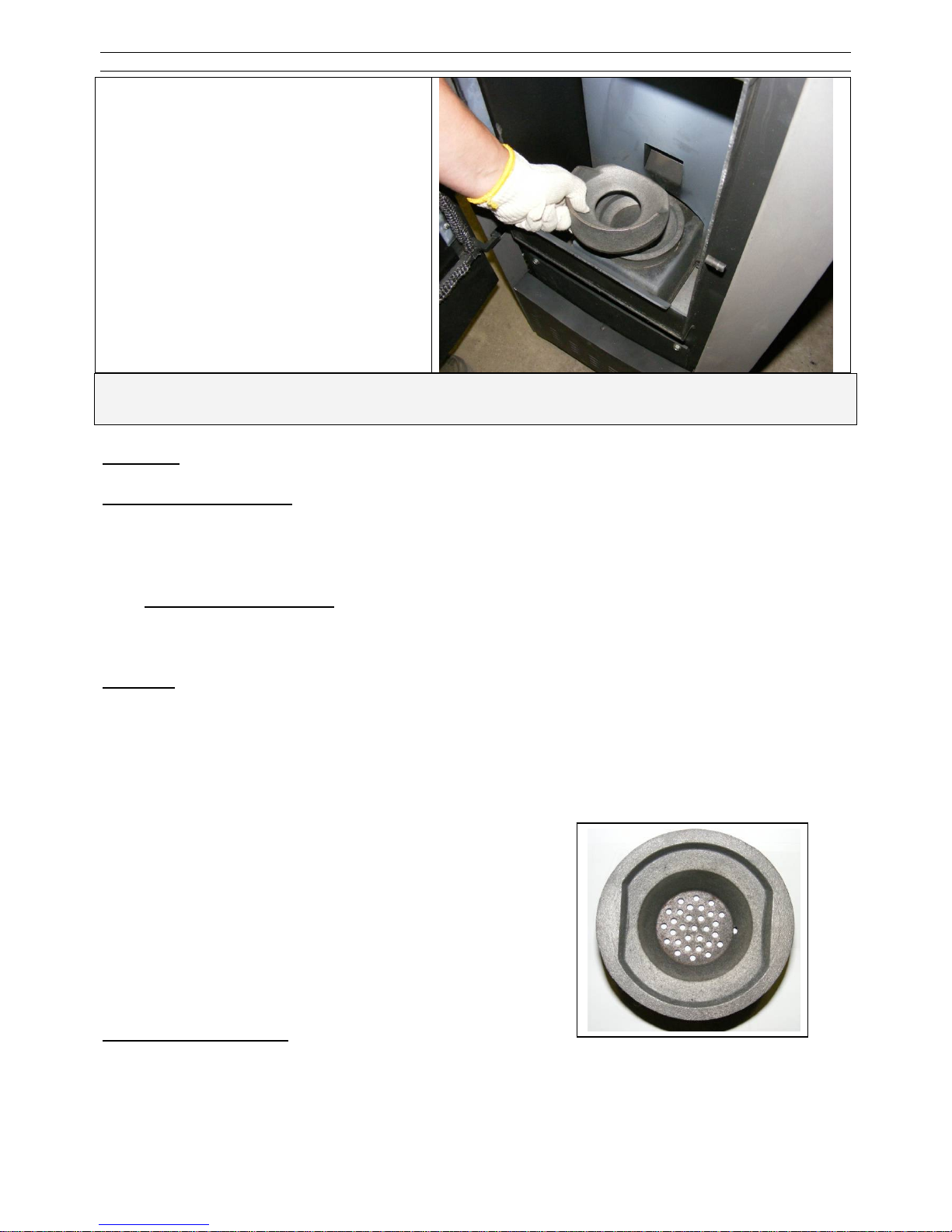
8.1. ÜBERPRÜFUNG UND REINIGUNG DES BRENNERTOPFES
Bitte überprüfen Sie täglich, jedoch spätestens jeden zweiten Tag den Brennertopf auf Verbrennungsrückstände (Asche/Schlacke). Spätestens bei 30 g Asche/Schlacke muss der Brennertopf und die Löcher gereinigt werden.
Hinweis:
Wird der Ofen im Dauerbetrieb beheizt, muss er unbedingt 2x innerhalb von 24 Stunden
abgeschaltet und der Brennertopf gereinigt werden. RÜCKBRANDGEFAHR!
Die Reinigung des Brennertopfs kann innerhalb weniger Sekunden während einer Betriebspause erfolgen, indem Sie die Asche mit dem Kratzer aus dem Brennertopf herausziehen bis
nur noch ein wenig Glut erhalten bleibt. Lassen Sie die Asche einfach in den Ascheraum fallen.
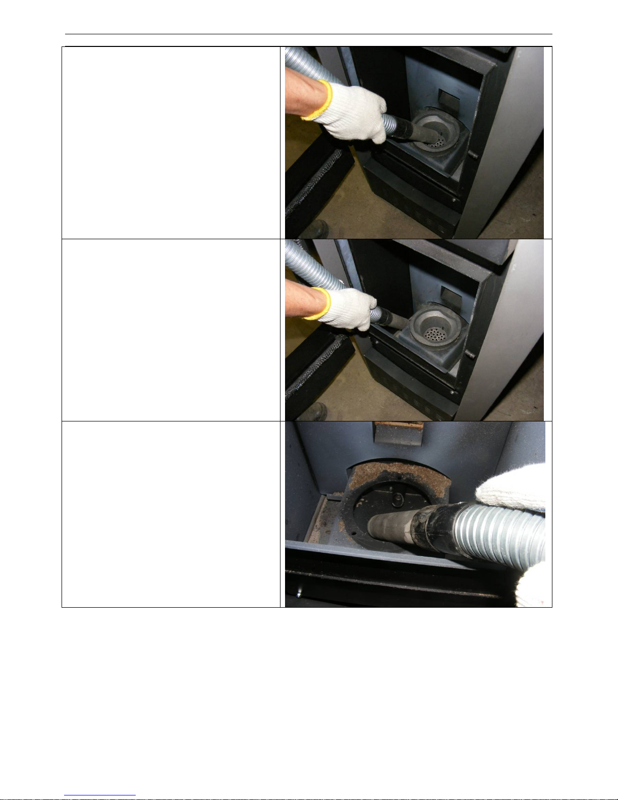
Wichtige Hinweise:
• Alle Öffnungen des Brennertopfs müssen
unbedingt frei sein.
• Um die Luftöffnungen nicht zu verstopfen, die
Asche nicht in den Brennertopf zerdrücken
oder zermahlen.
• Überprüfen Sie nach jeder Reinigung den
richtigen und satten Sitz des Brennertopfes
in der Aufnahme.
Vorsicht Brandgefahr:
Es besteht akute Brandgefahr bei Glutresten in der Asche. Saugen Sie Asche nur dann in
einen Staubsaugerbeutel, wenn Sie sich ganz sicher sind, dass keine Glut mehr enthalten ist.
Reinigung des Brennertopfes
Reinigen Sie den Brennertopf mit einem
Staubsauger und bei Bedarf mit einer
Bürste. Jede Öffnung muss frei von
Rückständen sein.
.
WP2-8_D 29 / 189
8.2. REINIGEN DER SICHTSCHEIBE
Ein Scheibenbeschlag ist normal und stellt keinen Mangel dar.
An der Sichtscheibe legt sich bei Festbrennstoffen, besonders bei der sehr feinen Asche von
Holzpellets ein Scheibenbeschlag an, der je nach Pelletqualität hell oder dunkel (speziell bei
kleiner Leistung) ausfallen kann. Das Glas der Feuerraumtüre reinigen Sie am besten mit einem
feuchten Lappen. Hartnäckiger Schmutz löst sich mit einem speziellen Reinigungsmittel (ohne
ätzende Säuren u. Lösungsmittel - Gefahr für die Glasoberfläche), das bei Ihrem Ofenfachhändler erhältlich ist.
Reinigung des Ascheraums
Mit dem Staubsauger reinigen Sie den
Ascheraum re./ li. und die Kanten der
Brennraumtür.
Achten Sie auf die Unversehrtheit der
Türdichtung!
Reinigung der Brennertopfhalterung
Nach Herausnahme des Brennertopfes
kann der Halterung von Rückständen
befreit werden.
Zum einsetzen des Brenntopfes achten
Sie auf die richtige Position!
WP2-8_D 30 / 189
8.3. REINIGUNG DER OBERFLÄCHEN
Lackflächen erst dann reinigen, wenn der Lack vollständig ausgehärtet ist, da der Lack sonst
verkratzt wird.
Die Pflege der äußeren Flächen ist nur bei kaltem Ofen zu empfehlen. Die lackierten Flächen
sollten nur mit klarem Wasser, vorsichtig und mit einem leicht befeuchteten, weichen Tuch gereinigt werden (nicht scheuern). Keinen Glasreiniger oder andere lösungsmittelhaltigen Reinigungsmittel verwenden. Vorab an einer nicht sichtbaren Stelle das Lackverhalten testen. Bei
pulverbeschichteten Flächen kann in besonderen Fällen vorher mit Seifenlauge oder etwas Geschirrspülmittel behandelt und dann leicht trocken gerieben werden.
Wartung
Vor der Wartung sollte zunächst eine komplette Grundreinigung des Brennertopfes, des
Brennertopfhalters und des Feuerraums stattfinden
Achtung / Gefahr:
BEACHTEN SIE BITTE ALLE SICHERHEITSHINWEISE VOM KAPITEL 8

WP2-8_D 31 / 189
8.4. REINIGUNG DER HEIZGASZÜGE
Demontage der oberen Abdeckung
Die obere Verkleidung kann mit einer
ruckartigen Bewegung nach oben abgezogen werden.
Demontage des Strahlschutzbleches
Nach dem Entfernen der zwei Flügelmuttern ist das Prallblech, schräg nach oben
aus dem Ofenkörper zu nehmen.

WP2-8_D 32 / 189
Demontage des Brennraumdeckels
Nach dem Entfernen der zwei Flügelmuttern ist der Brennraumdeckel, schräg
nach oben aus dem Ofenkörper zu nehmen.
Achtung!
Bei Wiedermontage achten Sie auf das
richtige Nachziehen der Schrauben
und auf die Unversehrtheit der Dichtungen!
Undichtigkeiten können zu Betriebsstörungen führen!
Entfernung des Umlenkbleches
Nach der Reinigung des Umlenkbleches,
kann dieses durch schräges Hochkippen
aus dem Ofenkörper heraus genommen
werden.
Achtung!
Bei Wiedermontage achten Sie auf die
richtige Position, da ein falsches einsetzen zu Betriebsstörungen führt!

WP2-8_D 33 / 189
Demontage des Reinigungsdeckels
Unteres Verkleidungsteil entfernen.
Danach die vier Schlüsselschrauben entfernen und den Deckel abnehmen.
Achten Sie auf die Unversehrtheit der
Dichtungen!
Achtung!
Bei Wiedermontage achten Sie auf das
richtige Nachziehen der Schrauben
und auf die Unversehrtheit der Dichtungen!
Undichtigkeiten können zu Betriebsstörungen führen!
Reinigung des Ascheraums
Nach dem Aussaugen ziehen Sie den
Aschekasten heraus.
Reinigung des Abgasabzugs
Nach dem Herausnehmen des Aschekastens kann man das Ventilatorengehäuse
reinigen.

WP2-8_D 34 / 189
Demontage der Wärmetauscher
Die zwei Wärmetauscher (re/ li.) können
durch leichtes wegdrücken der Luftleitbleche aus dem Ofenkörper herausgenommen werden.
Reinigung der Wärmetauscher
Saugen Sie die Abgasausgänge des
Wärmetauschers mit einem Staubsauger
aus und reinigen Sie evtl. Ablagerungen
mit einer Reinigungsbürste.
Loch auf der rechten Seite!
Den Zusammenbau des Ofens führen Sie wieder in umgekehrter Reihenfolge aus!
Auf Dichtheit und richtigen Zusammenbau achten!

WP2-8_D 35 / 189
8.5. KONTROLLE DER LUFTANSAUGUNG
Wenn eine externe Verbrennungsluftleitung an das Gerät angeschlossen ist, so sollte zunächst
diese Leitung auf der gesamten
Länge auf Verstopfungen optisch
kontrolliert werden, damit sichergestellt ist, dass zum Luftansaugrohr des Gerätes überhaupt ausreichend Verbrennungsluft zugeführt werden kann. Etwaige Verstopfungen und Ablagerungen
(z.B. Staubknäuel etc.) sind vollständig zu entfernen. Verbrennungsluftleitungen sollten an der
Mündung außerhalb des Gebäudes gegen Winddruck geschützt
angeordnet sein. Staub, Verschmutzungen, beziehungsweise
giftige und korrosive Dämpfe dürfen nicht zugeführt werden.
Achtung / Wichtig!
Auch das mit dem Schornstein verbundene Abgasrohr ist mit einer Reinigungsbürste zu reinigen. Bei dessen Versäumung können die Verbrennungsprodukte aus dem Brennraum schwerer
abtransportiert werden, was zu einer Betriebsstörung führen kann!
8.6. KONTROLLE UND REINIGUNG DER ELEKTRISCHEN BAUTEILE
Vorher nochmals kontrollieren ob der Netzstecker gezogen ist. Die Verlegung der elektrischen
Kabel optisch kontrollieren. Kabel dürfen insbesondere nicht über scharfe Kanten oder
heiße Stellen verlegt sein und keine Risse / blanke Stellen aufweisen. Defekte Kabel sind
auszutauschen. Elektrische Bauteile bei starker Verstaubung gegebenenfalls mit Pinsel entstauben und elektrische Kontakte bei Bedarf von Korrosionsrückständen befreien.
8.7. ABSCHLUSS DER WARTUNGSARBEITEN, PROBELAUF
Nach Ausführung der Wartungsarbeiten alle Anschlüsse wiederherstellen und Probebetrieb
durchführen.
9. BRANDSCHUTZBESTIMMUNGEN
Alle brennbaren Bauteile, Möbel, oder auch z.B. Dekostoffe in der näheren Umgebung
des Ofens sind gegen Hitzeeinwirkung zu schützen. Insbesondere die jeweils örtlich
gültigen Brandschutzbestimmungen und Vorschriften sind zu beachten.
Maß Wert Bedeutung
A 100 cm Mindestabstand im Strahlungsbereich / zu Warmluftaustritten
B 50 cm
Mindestabstand im Strahlungsbereich / zu Warmluftaustritten mit belüftetem
Strahlungsschutz
C 30 cm Mindestabstand außerhalb des Strahlungsbereichs
D 20 cm
Mindestisolierung Rauchrohr bei Wanddurchbruch mit Dämmung (nicht hinterlüftet)

WP2-8_D 36 / 189
Bilder zur Erläuterung der Brandschutzabstände
9.1. EINRICHTUNGSGEGENSTÄNDE IM STRAHLUNGSBEREICH
Im Sichtbereich (Strahlungsbereich) des Feuers muss zu brennbaren Bauteilen, Möbeln oder
auch z.B. zu Dekostoffen ein Abstand von mindestens 100 cm (Maß A), gemessen ab Vorderkante Sichtscheibe, eingehalten werden. Der Sicherheitsabstand reduziert sich auf
50 cm (Maß B), wenn ein belüfteter Strahlungsschutz vor das zu schützende Bauteil montiert
wird.
9.2. EINRICHTUNGSGEGENSTÄNDE AUßERHALB DES STRAHLUNGSBEREICHS
Alle brennbaren Bauteile, Möbel oder auch z.B. Dekostoffe in der näheren Umgebung des
Ofens sind gegen Hitzeeinwirkung zu schützen.
Die Stellwände seitlich und hinter dem Gerät dürfen nicht aus brennbaren Baustoffen hergestellt, oder mit brennbaren Baustoffen verkleidet sein, sofern ein Abstand von seitlich 30 cm
und hinten 20 cm unterschritten wird. Der Seitenabstand zu Möbelteilen aus Holz oder Kunststoff muss ebenfalls 30 cm betragen.
9.3. BODEN UNTER UND VOR DEM OFEN
Fußböden aus brennbarem Material wie Teppich, Parkett oder Kork müssen unter dem Ofen
sowie vor der Feuerraumöffnung mind. 50 cm nach vorne und mind. 30 cm seitlich über
die Feuerungsöffnung (nicht Außenkante des Gerätes, sondern Innenkante Feuerraumöffnung) hinaus durch einen Belag aus nicht brennbaren Baustoffen, z.B. Keramik, Stein, Glas
oder einer Bodenplatte aus Stahl, ersetzt oder geschützt werden.
Bodentragfähigkeit
Überzeugen Sie sich vor dem Aufstellen, ob die Tragfähigkeit der Unterkonstruktion dem Gewicht des Ofens standhält.
Es ist unterhalb des Ofens keine zusätzliche Wärmedämmung notwendig, es genügt
eine tragfähige und brandsichere Unterlage, da nach unten keine Wärmeabgabe erfolgt.
9.4. GEGENSTÄNDE IM BEREICH DER ZU- UND UMLUFTÖFFNUNGEN
Alle Luftein- und Luftaustrittsöffnungen sind immer freizuhalten und dürfen nicht versperrt oder
abgedeckt werden: Überhitzungs- / Brandgefahr!
Beispiel mit Verbindungsstück zum Schornstein inner-
halb des Aufstellraums
Beispiel mit Verbindungsstück durch Wand zum Schorn-
stein

WP2-8_D 37 / 189
9.5. ABSTÄNDE ZUM VERBINDUNGSSTÜCK (RAUCHROHR)
Verbindungsstücke müssen am Gerät und untereinander fest und dicht verbunden sein. Sie
dürfen nicht in den freien Schornsteinquerschnitt hineinragen. Das Verbindungsstück zwischen
Ofen und Schornstein soll den gleichen Querschnitt haben wie der Rohrstutzen am Ofen. Waagerechte Verbindungsstücke über 0,5 m sollen zum Schornstein hin um 10 Grad ansteigen.
Rohre, die nicht wärmegeschützt oder senkrecht geführt sind, sollen nicht länger als 1,5 Meter
sein.
Das Maß X (Abstand zu brennbaren Baustoffen/Materialien) muss nach Angaben des Herstellers des Verbindungsstückes eingehalten werden.
9.6. SCHORNSTEINANSCHLUSS
Das Gerät muss an einen für feste Brennstoffe genehmigten Schornstein angeschlossen werden. Der Schornstein muss einen Durchmesser von min. 120mm haben. Vermeiden Sie zu lange Rauchgaswege zum Schornstein. Die waagrechte Länge einer Abgasleitung sollte 1,5m
nicht überschreiten. Vermeiden Sie viele Richtungsänderungen des Abgasstromes zum
Schornstein. Es dürfen maximal 3 Bögen in der Abgasleitung verarbeitet werden. Sofern Sie nicht direkt gerade an den Schornstein anschließen können, verwenden Sie, wenn möglich, ein Anschlussstück
mit Reinigungsöffnung. Die Verbindungsstücke müssen aus Metall
ausgeführt sein und die Anforderungen der Norm erfüllen (die Anschlüsse luftdicht installieren). Vor der Installation muss unbedingt
eine Schornsteinberechnung durchgeführt werden. Die Nachweise
müssen für Einfachbelegung nach EN13384-1 und für Mehrfachbelegung nach EN13384-2 durchgeführt werden. Die Ableitung der
Rauchgase muss auch bei einem vorübergehenden Stromausfall gewährleistet sein.
Anschluss Direkt
Anschluss nach EN Prüfung
10. ZUGELASSENE BRENNSTOFFE
Nach der 1. Bundesimmissionsschutz-Verordnung (1. BImSchV) sind nur Naturbelassene Holzpellets zugelassen.
Es dürfen nur nach ENplus-A1, DINplus oder Ö-Norm M7135 geprüfte Pellets in unseren Pelletöfen eingesetzt werden. Es dürfen auch keine Holzpellets mit einem Aschegehalt von
> 0,5% verwendet werden, da sonst der Reinigungs- und Wartungsaufwand zu groß wird. Beachten Sie unbedingt die Hinweise zur Pelletqualität in Kapitel 3.5!
X

WP2-8_D 38 / 189
Stückholz oder andere Brenn- und Abfallstoffe dürfen niemals verwendet werden. Andere
Brennstoffe führen auch zur Beschädigung und belasten unsere Umwelt. Wird der Ofen mit
nicht zugelassenen Brennstoffen betrieben, erlöschen sämtliche Gewährleistungs- und Garantieansprüche und es können gefährliche Betriebszustände entstehen. Unternehmen Sie keine
Experimente. Ein Pelletdurchmesser zwischen 5 und 7 mm ist zulässig. Die Durchschnittslänge
der Pellets sollte 30-35 mm nicht überschreiten. Pellets mit zu hohem Staubgehalt (> 5%) sollten ebenfalls nicht verwendet werden.
11. LAGERUNG VON PELLETS
Holzpellets werden in absolut trockenem Zustand ausgeliefert und können unmittelbar für das
Heizen im Pelletofen verwendet werden. Um die Qualität der Pellets zu erhalten, muss der
Brennstoff trocken und frei von Verschmutzungen gelagert werden.
Pellets sollten auch in Säcken nicht im Freien oder der Atmosphäre ausgesetzt gelagert werden. Durch die erhöte Luftfeuchtigkeit nehmen die Pellets Wasser auf, dies kann zu Verstopfungen in der Förderschnecke führen.
12. KUNDENDIENST / ERSATZTEILE
Kundendienst, Wartung und Ersatzteile erhalten Sie über Ihren Fachhändler. Er informiert und
unterstützt Sie auch in allen anderen Fragen rund um Ihren WAMSLER Pelletofen.
Sollten Sie jemals ein Problem mit Ihrem Gerät haben oder lassen sich Störungen nicht beheben, wenden Sie sich bitte an Ihren Fachbetrieb.
Bitte geben Sie bei Beanstandungen oder einer Bestellung von Ersatzteilen unbedingt
die Fertigungsnummer vom Typenschild Ihres Gerätes und das Kaufdatum an, damit Ihnen fachgerecht geholfen werden kann und die richtigen Ersatzteile zum Einsatz kommen.
13. IHR FACHBETRIEB
Behagliche Wärme und viele gemütliche Stunden mit
Ihrem WAMSLER Pelletofen wünscht Ihnen
Ihre WAMSLER Haus und Küchentechnik GmbH.
WAMSLER Haus- und Küchentechnik GmbH • Adalperostraße 86 • D-85737 Ismaning
Telefon: +49 (0)89 32084 – 0 • Telefax: +49 (0)89 32084 – 238 • Internet: www.wamsler.eu
Fachbetrieb:

WP2-8_GB 39 / 189
Before installing and commissioning your appliance, please read these operating instructions
carefully. In this way, you can avoid damage arising from unprofessional installation or
operation. As a result, your appliance will safeguard the environment by operating in an optimal
manner.
WAMSLER Haus und Küchentechnik GmbH wishes you coziness and warmth, as well as plenty
of hours to be spent with your pellet boiler.
TABLE OF CONTENTS
TABLE OF CONTENTS ______________________________________________________________________ 7
1. IMPORTANT GENERAL INSTRUCTIONS ___________________________________________________ 7
2. SCALE DRAWING, CABLING DIAGRAM ____________________________________________________ 7
3. SYSTEM REQUIREMENTS ______________________________________________________________ 7
3.1. MINIMUM OPERATING TIMES / APPLICATION OF EXTERNAL REGULATORS ________________ 7
3.2. ROOM TEMPERATURE / AMBIENT TEMPERATURE / HUMIDITY FOR OPERATION____________ 7
3.3. CONNECTION TO CHIMNEYS _______________________________________________________ 7
3.4. SUPPLY OF THE COMBUSTION AIR __________________________________________________ 7
3.5. QUALITY OF THE PELLET __________________________________________________________ 7
3.6. CLEANING, MAINTENANCE AND CARE _______________________________________________ 7
3.7. ELECTRIC POWER SUPPLY_________________________________________________________ 7
4. THE APPLIANCE AND THE DESCRIPTION OF ITS OPERATION ________________________________ 7
4.1. TECHNICAL SPECIFICATIONS_______________________________________________________ 7
4.2. SCOPE OF SUPPLY _______________________________________________________________ 7
4.3. DESCRIPTION OF THE OPERATION __________________________________________________ 7
4.4. FIRST COMMISSIONING____________________________________________________________ 7
4.5. BEFORE STARTUP / IGNITION_______________________________________________________ 7
4.6. OPERATING AND HEATING MODE ___________________________________________________ 7
4.7. TEMPERATURE MENU _____________________________________________________________ 7
4.8. USER MENU______________________________________________________________________ 7
4.9. GENERAL SETTINGS ______________________________________________________________ 7
4.10. SETTINGS MAIN MENU_____________________________________________________________ 7
5. START_______________________________________________________________________________ 7
5.1. REACHING THE TEMPERATURE (TEMPERATUR) VALUE ________________________________ 7
5.2. SETTING THE TIMER ______________________________________________________________ 7
5.3. DISABLING THE AUTOMATED MODE _________________________________________________ 7
5.4. DISCHARGING/CHARGING THE PELLET TANK _________________________________________ 7
6. STAND-BY (SWITCHING OFF) ___________________________________________________________ 7
6.1. BOILER SWITCHES OFF____________________________________________________________ 7
6.2. ACKNOWLEDGMENT OF THE ALARM_________________________________________________ 7
7. ELECTRIC POWER SUPPLY _____________________________________________________________ 7
7.1. FUSE REPLACEMENT______________________________________________________________ 7
7.2. RESETTING OF THE SAFETY TEMPERATURE LIMITER (STB) ____________________________ 7
7.3. CONNECTION OF THE EXTERNAL ROOM THERMOSTAT ________________________________ 7
8. CLEANING AND CARE__________________________________________________________________ 7
8.1. INSPECTING AND CLEANING THE BURNER PAN _______________________________________ 7
8.2. CLEANING THE INSPECTION WINDOW _______________________________________________ 7
8.3. CLEANING THE SURFACES _________________________________________________________ 7
8.4. MAINTENANCE ___________________________________________________________________ 7
8.5. CLEANING THE HOT GAS PASSAGES ________________________________________________ 7
8.6. CHECKING THE AIR INLET__________________________________________________________ 7
8.7. CHECKING AND CLEANING THE ELECTRICAL PARTS___________________________________ 7
8.8. COMPLETION OF MAINTENANCE WORKS, TEST OPERATION ____________________________ 7
9. FIRE PROTECTION REQUIREMENTS _____________________________________________________ 7
9.1. FIXTURES IN THE RADIATION RANGE ________________________________________________ 7
9.2. FIXTURES BEYOND THE RADIATION RANGE __________________________________________ 7
9.3. FLOOR UNDER AND IN FRONT OF THE BOILER ________________________________________ 7
9.4. OBJECTS IN THE RANGE OF THE AIR SUPPLY AND AIR CIRCULATING OPENINGS __________ 7
9.5. DISTANCES FROM THE CONNECTING PROFILES (FLUE) ________________________________ 7
9.6. CHIMNEY CONNECTION ___________________________________________________________ 7
10. PERMITTED FUELS __________________________________________________________________ 7
11. STORAGE OF THE PELLET ___________________________________________________________ 7
12. CUSTOMER SERVICES / SPARE PARTS_________________________________________________ 7
13. YOUR SPECIALIZED COMPANY________________________________________________________ 7

WP2-8_GB 40 / 189
1. IMPORTANT GENERAL INSTRUCTIONS
The installation and operation of the heating equipment shall comply with all the
instructions of the manufacturer, the European standards and the standards of the
country where the furnace is installed and operated. This is how malfunctioning and
operating faults can be forestalled.
Before the commissioning of the boiler, the operator of the boiler is obliged to consult
the instructions to become familiarized with the particular properties of the heating
equipment and the appropriate fuels.
The pellet furnace can be operated only with wood pellet of natural conditions (6 mm Ø) as
defined in standard EN-PLUS A1, DINplus or Ö-Norm M7135. Never use any shredded wood
or other fuels, waste materials.
In Europe, European Standard EN 13384 pertains to chimneys, EN 15287 to flue exhaust
equipment and EN 1856-2 to connecting elements.
Furthermore, in Germany the following requirements are also valid: Decree on heating
(Feuerungsverordnung (FeuVO), Provincial decrees on construction, Electricity/VDE
guidelines ( Elektro - / VDE-Richtlinien ) and Professional regulations on heating and air
heating. Besides, Federal Emission Protection Decree 1 (1. Bundes-Immissionsschutz-
Verordnung (1. BImSchV) also needs to be observed. Before commissioning, the specific
locations of heating have to be accepted by the competent chimney-sweeper. The associated
protocol of acceptance shall represent the commissioning permit.
When the appliances is operated jointly with any air engineering equipment (for instance
ventilation equipment, vapour exhauster, pneumatic conveyor, etc.) the relevant technical
rules / requirements (in Germany, among others, ventilation and heating can be combined
only are permitted in Article 4 of FeuVO) shall be observed.
Hereunder, the requirements associated with use for the intended functions are
discussed.
All the other applications are deemed as use beyond the intended functions.
We cannot assume
liability for any related damage
. Use in line with the intended functions involves the proper
observance of the operating and installation instructions. Any unauthorized intervention and
modification on the equipment may result in the invalidation of warranty and guarantee
demands.
Any work on the appliance, especially installation, repairs, first commissioning, servicing
and corrections may be carried out solely by professional contractors (heating engineering
and air heating contractors). Any unprofessional intervention may lead to the invalidation of the
warranty and guarantee. Electrical appliances may be connected and serviced only by
electricians. Electronic structural elements, including, without limitations, printed circuit boards
and operating boards are electrostatically sensitive.
Within the framework of ultimate delivery, the professional contractor is obliged to train the
operator thoroughly and professionally in operating, cleaning and maintaining the equipment.
Particular attention shall be paid to the use of appropriate fuels, regular cleaning to be
performed by the operator, the necessary maintenance, as well as compliance with the safety
requirements. It is especially important to emphasize that any non-observance of the
instructions, or the failure to perform the prescribed cleaning and maintenance operations may
result in the invalidation of the warranty and guarantee.

WP2-8_GB 41 / 189
Before commissioning, it shall always be ensured that all the accessories have been removed
from the combustion chamber and ash compartment, while the pellet storage space should
not hold any residual material.
The operator has to clean the combustion chamber regularly.
To maintain the heating equipment, it is recommended to conclude a maintenance agreement
between the specialized company and operator. The regular maintenance may also be
performed by the operator having been thoroughly trained by the specialized company, under
technically safe conditions.
Before the commencement of works, the supply power cord shall be disconnected. The
supply power connection and the socket shall always be easily accessible. It is forbidden to
operate the appliance with a damaged power cord. In case the power supply cord is damaged,
it shall be instantly replaced by a qualified expert in order to avoid emergency situations. It is
forbidden to unplug the boiler in the course of operation! The boiler shall be switched off
in advance, and the operator shall wait until the equipment fully stops (the fuel burns
down).
Correct operation / handling, as well as appropriate care and maintenance increase the
lifetime and preserve the value of the equipment. It saves valuable resources, spares the
environment and your money.
2. SCALE DRAWING, CABLING DIAGRAM

WP2-8_GB 42 / 189
Sicherung - fuse
Schneckenmotor - worm wheel engine
Differenzdruckschalter differential pressure switch
Raumluftventilator - room air fan
Abgasventilátor - exhaust gas fan
Kabelbaum - cable harness
Erde - ground cable
Nulle - neutral cable
Phase - phase conductor
Raumtemperature - room temperatures
Externe Thermostat…. external thermostat (option)
Abgastemprature - exhaust gas temperatures
red - red
blau - blue
schwarz - black
weiss - white
Panel console - panel support bracket
Grundkörper - base
Verbinder - connector
Signal - signal
Tastaturverbinder - keyboard connector
Zündkerze - ignition plug

WP2-8_GB 43 / 189
3. SYSTEM REQUIREMENTS
Our appliances are always connected to other equipment / products of the construction industry,
and therefore, as for all technical products, there are certain system requirements in connection
with undisturbed operation. Hereunder, a few important requirements are specifically detailed.
The list below has not been intended to be all inclusive. All the instructions / data mentioned
above shall also be taken into consideration. In advance, the operation of the equipment has to
be planned thoroughly by a specialized company so that the individual system components
should be accurately aligned with each other, and the intended full-scale solution should be
realized.
3.1. MINIMUM OPERATING TIMES / APPLICATION OF EXTERNAL REGULATORS
The pellet is a solid fuel whose ignition takes more time than that of any liquid or gas fuel. Until
the appearance of the first flame, a few minutes elapses after startup. The equipment can be
operated at full performance after the completion of the warm-up program. When the appliance
is switched off, it takes a few minutes – unlike gas or oil combustion – until the pellet burns off,
and the flame dies out. For this reason, the appliance is programmed with a few minutes of fan
follow-up operating time (see the "INFO" message on the display) that has to elapse until the
boiler can be turned on again.
Therefore, the minimum operating time needs to be considered when the appliance is regulated
with any external controller. For this reason, the follow-up operating time is programmable
among the control options (to be set under the "INFO" menu). When the controller reaches the
rated temperature, then the boiler continues to operate for the follow-up operating time before
the commencement of the burn-off mode. (This function can be set optionally in the menu.)
3.2. ROOM TEMPERATURE / AMBIENT TEMPERATURE / HUMIDITY FOR OPERATION
All the appliances are designed for operation solely in residential rooms, where normal humidity
and temperature in the range from +5°C to +30°C prevails (ambient temperature during
operation).
Boilers are not protected against splashing water, and cannot be installed in humid rooms.
Because of the operating noise of boilers and the noise caused by the flames, the installation of
boilers is not recommenced in bedrooms and rest rooms. During operation, falling pellets may
cause noise, burning may occur, or the noise caused by flow mechanisms and drive engines
may be heard. When the temperature is < 5 °C (for example, in holiday homes), the appropriate
minimum settings have to be performed on the boiler, and furthermore adequate freezing
inhibitors (for instance, electric heating) shall be provided. When operating at > 25 °C
temperature, safety equipment is necessary. See the requirements pertaining to the heating
mode in the operating instructions of the appliances.
3.3. CONNECTION TO CHIMNEYS
It is mandatory to have the appliance connected to a chimney that is suitable for use with
solid fuels. The connecting profile has to be made from metal. Your competent chimney
sweeping company will be pleased to provide you with advice. With multiple loading (operation
of pellet-fueled equipment via a single chimney), in Germany the requirements of Standard DIN
18896 have to be observed. The carriage pressure (chimney draft = vacuum) shall be in the
range from 6 Pa to 15 Pa (with 12 Pa being the rated value). Before installing the boiler, the
chimney planning routine always has to be performed as per Standard EN 13384 so that the
chimney could be loaded up to 400°C at the maximum. Especially at times of power outage, the
chimney has to ensure the safe carriage of the flue gas from the appliance, and therefore the
chimney has important safety functions. When the chimney draft is too large, the incorporation
of a draft regulator is recommended. See Section 10.6.

WP2-8_GB 44 / 189
3.4. SUPPLY OF THE COMBUSTION AIR
The appliances operate as depending on the room temperature. Proper combustion air
supply is absolutely necessary. There may not be any shortage of pressure in the room of
installation. For this reason, in the case of combined installation and operation with air
engineering equipment (for example, ventilation equipment, vapour exhausters, pneumatic
conveyors, etc.), the relevant technical rules / requirements of the combustion decree (in
Germany, Article 4 of FeuVo) have to be observed.
When the boiler is operated in combination with air engineering equipment, as depending on the
room temperature, then provisions shall be made for the mutual closing of the devices, or such
air engineering equipment needs to be incorporated that is permitted to be operated with solid
fuels. In the room of installation, sufficient combustion air (approximately 25-30 m³/h) shall be
conducted to the appliance.
3.5. QUALITY OF THE PELLET
Within the meaning of the 1st Federal Emission Protection Decree (1. BImSchV), solely natural
wood pellet can be used in Germany. The quality of the pellet has a crucial influence on the
cleaning and maintenance cycles.
All our data and control values have been given as relating to pellet of 0.25 percent ash content,
650 kg/m³ specific weight and Hu > 4.9 kWh/kg calorific value. As a result, the energy content of
500 liters of fuel oil corresponds to the energy content of 1000 kg of wood pellet of the above
quality. To store 1000 kg of pellet of the above quality, approximately 1.54 m³ volume is
necessary. Deviations from the above-specified values cannot be avoided within the standard
tolerance limits relating to the pellet (such as the ones defined in ENplus-A1, DIN-PLUS, DIN
51731 or Ö-Norm M7135), in association with, for instance, the ash content, specific weight,
composition and size/geometry, which evidently leads to differences in the various data.
For instance, when ash content is doubled from 0.25% to 0.5%, the cleaning and maintenance
frequency will become halved. According to Standard DIN 51731, the pellet distributed in the
market can have ash content of even 1.5%. In the case of such worse quality, the cleaning and
maintenance intervals drop to the sixth of the standard value! For the boilers we distribute, the
ash content of the pellet is by far the most important value. We recommend the application of
such pellet quality in our appliances that is tested under Standard ENplus-A1, DIN PLUS or Ö-
Norm 7135, and their ash content is < 0.7%.
The average ash content of commercially available, good quality, branded pellets is < 0.3% on
the average.
Ask your own pellet supplier about the ash content of the delivered pellet. The smaller it is, the
better you can use it. Due to the allowable natural binding agents used as additives, the pellet
ash still can solidify in the combustion chamber, in spite of the tests performed according to the
above standards. For this reason, the application of binding agents containing silicate, such as
potato starch or corn starch, are not recommended. In this respect, consult your pellet supplier
again. In the case of any large specific weight, special geometry and large calorific value, the
internal safety equipment can reduce the performance of the boiler on a temporary basis, until it
reaches the level of the rated performance. It does not indicate any failure. The appliance
modulates itself.
In the case of pellets of very small specific weight or excessively small calorific value, the
equipment may remain under the specific rated performance values or performances ranges. It
does not mean any malfunctioning, but is caused by the conditions of the fuel. The specialized
company can set the boiler to operate with fuels of various conditions and different pellet
qualities. It is forbidden to burn shredded wood or other fuels, wastes. If the boiler is operated
with unpermitted fuels, then all the warranty and guarantee demands will become invalid, and
hazardous operating conditions may occur. Do not experiment with other fuels!
The allowable diameter of the pellet is in the range from 5 to 7 mm. The average length of the
pellet may not exceed 30 mm. Pellets of large dust contents (> 5%) cannot be used, either.

WP2-8_GB 45 / 189
3.6. CLEANING, MAINTENANCE AND CARE
Unlike with liquid and gas fuels, solid fuels always generate ash and soot. The quality of
combustion and handling comfort of pellet boilers are far better than those of similar boilers
operated with shredded wood, yet the burning pan is to be cleaned (by the operator) with
shorter intervals, while maintenance and checking become necessary less frequently in order
to remove soot and ash from the equipment. If it is not performed, the boiler may malfunction,
foe which we cannot assume liability. Regular care, cleaning and maintenance help to preserve
the efficiency of your equipment, as soot is an excellent insulating agent, and therefore it
considerably reduces heat dissipation and effectiveness, while unnecessary emissions to the
environment can also be avoided. Cleaning interval: the combustions chamber has to be
inspected visually, and manually cleaned as necessary.
Maintenance interval: Use of 1500 kg of pellet (featuring 0.25% ash content). See also Section
3.5 and 8 of these instructions.
3.7. ELECTRIC POWER SUPPLY
230 V AC / 50 Hz (allowable range of fluctuation: 195–255 V).
See also the provisions of Section 7 of these instructions.
4. THE APPLIANCE AND THE DESCRIPTION OF ITS OPERATION
4.1. TECHNICAL SPECIFICATIONS
WP2-8A WP2-8KA
maximum rated heat output
minimum rated heat output
maximum fuel consumption, approximately
minimum fuel consumption, approximately
efficiency (NWL)
efficiency (under partial loading)
chimney draft (min.)
chimney draft (max.)
capacity of the pellet tank, approximately
connection to the electric power supply network
frequency
maximum power consumption
diameter of the exhaust gas stub
weight, approximately
kW
kW
kg/h
kg/h
%
%
Pa
Pa
kg (liter)
V
Hz
VA
mm
kg
7.5
2.5
1.9
0.6
90.5
95
6
12
21 (32)
230
50
350
80
96
6.5
2.5
1.9
0.6
90
96
6
12
21 (32)
230
50
300
80
94
Important note:
Immediately after the commissioning of the equipment, from the rating table record the
manufacturing number of the boiler, and keep the invoice. In guarantee-related cases or for
subsequent parts supply, the article number and manufacturing number of the boiler are
always needed so that the suitable spare parts can be delivered to you. Without knowing the
manufacturing number and the date of purchasing, we cannot accept guarantee-based
performance, and the option of defective supply cannot be excluded, either. All the documents
provided with the equipment shall be kept carefully, as it promotes the work of customer
services when required, and facilitates the situation of the future owner of the equipment.
After purchasing, note down manufacturing number of your equipment:
_______________

WP2-8_GB 46 / 189
4.2. SCOPE OF SUPPLY
The scope of supply covers the following appliances:
• Heat-resistant gloves, accessory tool to open the door, operating instructions.
4.3. DESCRIPTION OF THE OPERATION
WAMSLER pellet boiler is a special heating equipment for household use, and is suitable for
burning only 6 mm Ø wood pellet as described in Standard ENplus A1. The heating mode the
equipment produces hot air, which radiated to the room. To use the heating option, simply
switch on the boiler, and choose the desired performance grade. When an external regulator is
used, the pellet-burning boiler automatically switches on and off, and the performance grade
can also be modulated automatically. Wood pellets are fully automatically carried by the
equipment to the combustion chamber, and ignited by means of electronic ignition.
Corresponding to the selected performance grade, the controlled conveyor worm transfers the
appropriate fuel quantity. The air needed for combustions flows to the combustion chamber in a
controlled manner. The gas burns in the combustion chamber and the connected flue gas
discharge units, and transmits its energy to the environment.
At the ends of the hot gas passages, an exhaust fan can be found that safely conducts the
outlet gases to the chimney as appropriate for the quantity of fuel and volume of combustion air.
The operator is required to clear the ash and cinder from the combustion chamber at regular
intervals. The inspection window shall also be cleaned from the deposited ash, which is always
generated when solid fuels are burnt. The hot gas passages also have to be maintained
regularly. It needs to be carried by a specialized company.
Solid fuels naturally leave soot behind, and therefore the contamination of the inspection
window cannot be fully avoided, but it does not represent any deficiency.
Before being installed in the residential spaces, boilers have to be planned, reviewed and
authorized. For burning, the inflow of a sufficient volume of oxygen needs to be ensured. For
this reason, boilers can be operated with air engineering equipment – such as vapour
exhausters, ventilation equipment or pneumatic conveyors used for the carriage of wood pellet
– only under specific conditions. Consult any associated issue with the locally competent
chimney sweeping company or specialized contractor.

WP2-8_GB 47 / 189
Cross-section of operation
WP2-8A WP2-8KA
with a convectional fan without a convectional fan
4.4. FIRST COMMISSIONING
Important instructions:
• Always keep the door of the combustion chamber closed, even when it is cold.
• In heating made, all the surfaces can become extremely hot, especially the inspection
windows, handles and control elements. Call the attention of children, young and elderly
people to this threat, and ensure that the animals that may be in the surroundings should not
be injured. Ensure that no one should be in the hazardous vicinity of the boiler when it is in
operation. To handle the boiler, use the protective gloves or accessories provided with the
equipment. In the absence of a supervisor, children and young people under the age of 16
cannot operate the boiler.
• In continuous operation, your clothes may as well become hot. Use the heat-resistant
protective gloves provided together with the equipment.
• All the parts of the boiler made from steel or cast iron have been coated with heat-resistant
varnish, which has been burnt on the metal. When a new pellet boiler is first heated up, the
varnish still in the process of drying, and therefore smoke and unpleasant smell can be
generated! In this respect, it is worth accepting the following advice:
o Ventilate the room thoroughly in order to discharge the released steams.
o During the period of hardening, the varnish is still soft. Do not touch the varnished
surfaces to avoid damage to them.
o After operation at high heating performance, the hardening of the varnish becomes
complete.
When the equipment has been completely equipped in line with the installation instructions,
then pellet can be fed into the storage tank. Fill at least 5 kg wood pellet into the storage tank.
At this time, no other objects can be in the pellet tank, the combustion chamber or at the
burner.

WP2-8_GB 48 / 189
Filling the supply tank
Open the cover of the tank. Tear the seam of the pellet bag open, and with its opening looking
downwards let the bag down to the screen grid, into the supply tank, and finally slowly
discharge the contents of the bag into the tank. After filling, close the cover of the tank, which
shall be always kept closed during operation.
Our recommendation: Pour the pellet slowly into the tank from just a little height, because it
would generate less dust. The pellet can be filled into the supply tank with the use of a bucket
or similar tool, as well.
Important: ACT CAUTIOUSLY when filling the tank! The pellet bag may not come in contact
with the pellet bag. Immediately remove the pellet that has not entered the tank!
Warning! Foreign bodies may not be dropped into the supply tank, and therefore the
associated damage is not covered by our guarantee / warranty.
Procedure to switch the appliance on
At the time of the first commissioning the conveyor worm is still fully empty. After first switching
the appliance on, it takes some 10 minutes to have the first pellets falling into the burner pan,
and then ignition switches off again. The same applies to the case when the supply tank is filled
up too late, and the equipment operates fully empty.
Procedure to ignite the equipment safely:
• Turn the equipment on with the I/O switch, and then wait for the heating program to
complete, and the first pellets to fall into the burner pan.
• Turn the appliance off instantly with the use of the I/O switch, and then reset it after 5
seconds. The warm-up program is completed again, and when the first pellets fall into the
burner pan, the appliance ignites. The ignition program has to be repeated as required.
Our recommendation:
When the supply tank has become fully empty, and there is no pellet in the conveyor worm, the
time period needed for feeding pellet to the burner pan again, and igniting the appliance by
transferring a handful of pellet to the burner pan via the first row of holes.
Warning! The burner pant should not be completely filled, as it may result in malfunctioning!
4.5. BEFORE STARTUP / IGNITION
Important: The process of ignition can take up to 10 minutes after the visible appearance of the
first flame (as depending on the cleanliness of the burner pan), the equipment restarts after
each resetting or power outage.
• Open the door of the combustion chamber. Ensure that there is no contamination or pellet in
the burner pan and the combustion chamber, and clear the pellet, ash and cinder off the
burner pan.
• Close the doors.
• Switch the equipment on with the use of the I/O keys. Start feeding the pellet to the burner
pan. The ignition element of the equipment performs ignition automatically. The pellet
starts burning in 5–10 minutes at the latest.
• If no ignition occurs (the pellet does not burn in the burner pan), then examine the
contamination of the burner pan first (with all the ventilation openings being unobstructed),
and whether the supply tank has been filled. Or pass the pellet through the worm, which
takes approximately 10 minutes if it is the first time the appliance is switched on, or the
supply tank has become fully empty. Before restarting, fully clean the burner pan.
When
the startup process has failed, fully empty the burner pan, and remove the pellet that
has not burnt off and the ash. It is prohibited to feed back any unburnt pellet into the
supply tank again, or ignite it in the burner pan.
• They pose fire hazards due to the glowing residual materials and/or overheating!

WP2-8_GB 49 / 189
4.6. OPERATING AND HEATING MODE
There are various keys to operate the appliance, completed by displays and indicators. In
general, the appliance can be operated with the I/O key, as well as the "+" and "-" keys.
P1 Press to enter the timer menu.
P2 ON / OFF - key
P3 HELP - key
P4 SET - key – Press to enter the - "Change parameters" menu
P5 "+"- key - increase
P6 "-" - key - decrease
L1 LED – thermostat - ON – OFF
L2 LED – operation - ON (even when it is not active) – OFF (the system is in OFF (AUS)
status)
A display / screen
B Red-ray remote control (inactive)
Setting the contrast of the screen
It is possible only in the main menu. Press P5 to increase, and the P6 key to decrease.
Illumination of the screen
It is possible only in the main menu. To increase or decrease the illumination, press the P3 key
concurrently with P5 or P7.
Changing the temperature
Press the P4 key until the menu shows the room temperature. To change the values, press the
P5 or P6 keys (this menu setting is not available when an external thermostat has been
activated).
Access to the Chrono – Thermostat menu
Press the P1 key for approximately 5 seconds.
HILFE (HELP) – key (P3). Information by pressing the P3 key can be displayed for
approximately 10 seconds.
For the ON / OFF function, press the P2 key for approximately 3 seconds.
Open the information pertaining to the boiler
Press the P1 and P2 keys concurrently. The equipment status appears on the screen. Press the
P4 (MENU / SET) key for approximately 5 seconds.
Use the P5/P6 keys to select the menu to be preferred.
Press the P4 (SET) key to make your selection. Press the P5 and P6 keys to change the
settings.

WP2-8_GB 50 / 189
4.7. TEMPERATURE MENU
The menu functions can be changed with the use of the P4 (SET / Menu) key.
1. Current room temperature.
2. Set room temperature.
Use the P5 / P6 keys to increase or decrease the set temperature. Press the P4 key to
acknowledge the set temperature.
Press the P4 key again to return to the main menu.
4.8. USER MENU
Menu structure:

WP2-8_GB 51 / 189
Raum T Einstellung setting the room temperature
Menue
menu
Set
setting
User Menue
user menu
Service Menue
service menu
key
key
and
and
Schaltuhr Einst.
setting the timer
Quittieren
acknowledgment
Pelletzufuhr
pellet feeding
Offenstatus
boiler status
Pelletsorte-Einst.
setting the pellet quality
Raumgebläse-Einst.
setting the room fan
Hauptmenü
main menu
Schaltuhr-aktiv
timer active
Komforttemp.
comfort temperature
Normaltempl.
normal temperature
Economytemp.
economical temperature
Schaltzeitenprog.
programming the times for switching on
Datum/Uhrzeit
date/precise time
Fernbed…..
remote control (yes/no)
Sprachwahl
selection of the language
Störungscode
error codes
Wartung
maintenance
Foerderd. Menu
supply menu
Abgassensoreinst.
setting the exhaust gas detector
Werkeinstell.
factory setting
Funtionstest
operating test
Parametereinst.
setting the parameters
Zufuhrtest
feeding test
Fernbedienung
remote control
password
password
Enter the use menu by pressing the P4 key for longer (approximately for 3 seconds).
Quittieren: return to the main menu
VORFUELLEN: PELLET FEEDING function
(it can be set only when the appliance is switched off,
two setting options are available)
OFENSTATUS: information on the current status
PELLETSORTE-EINST.: setting the pellet quality
RAUMGEBLÄSE-EINST.: setting the room temperature fan within the allowable limits
HAUPTMENUE: setting the date /precise time / display / standby mode /
language

WP2-8_GB 52 / 189
4.9. GENERAL SETTINGS
The main menu has two sides, and you can move between them with the P5/P6 keys:
First menu page:
Quittieren: return to the main menu
DATUM/UHRZEIT: setting the precise time / date
DISPLAY DEKO: activation / inactivation of the duration of the lighting of the display
STAND-BY: activation / inactivation (switching off) of the Standby function
FERNBED. (Y/N): activation / inactivation of the remote control (it does not belong to the
scope of supply)
SPRACHWAHL setting the language (DE/IT/HU)
Second menu page:
STOERUNGSCODES: Displaying the registered fault reports (ALARMS) that are stored in
the log file.
WARTUNG: Information of the maintenance

WP2-8_GB 53 / 189
4.10. SETTINGS MAIN MENU
DATE / PRECISE TIME
Enter this menu by pressing the P4 key shortly.
These values can be set with the use of P5 and P6 keys. It is not necessary to set the weeks of
the day.
Return to the menu by pressing the P4 key longer.
DISPLAY OFF
The P4 key activates/inactivates the display mode in case no other key is pressed for 300
seconds. These values can be set with the use of P5 and P6 keys.
STANDBY
Select and press the P4 key shortly to enter this menu.
The values can be set by using the P5 and P6 keys, while the P4 key has to be pressed shortly
for acknowledgment and exit.
FERNBEDINUNG (J/N) / REMOTE CONTROL (YES/NO)
Select and press the P4 key shortly to enter this menu.
The values can be set by using the P5 and P6 keys, while the P4 key has to be pressed shortly
for acknowledgment and exit (not available).
SPRACHWAHL / LANGUAGE SELECTION
Select and press the P4 key shortly to enter this menu.
The values can be set by using the P5 and P6 keys, while the P4 key has to be pressed shortly
for acknowledgment and exit.
5. START
Pressing the P2 (ON/OFF) key for approximately 2–3 seconds.
The program automatically examines the following conditions.
INITIAL CLEANING CONDITIONS
Operation of the exhaust fan for 5 seconds.
HEATING CONDITIONS
Ignition switches on with the exhaust gas fan. Duration: 180 seconds.
FULL LOADING CONDITION
The worm switches on together with the exhaust gas fan for 60 seconds.
STAND-BY CONDITION
The worm stops for 120 seconds (PA04 parameter) in order to facilitate the ignition of the pellet.
CONDITION OF SWITCHING ON
The exhaust gas fan and worm are active for 1500 seconds.

WP2-8_GB 54 / 189
Transmission to the next phase occurs only when the temperature of the exhaust gas rises over
the smallest allowable value (50 °C).
If this phase does not occur within the allowable 1500-second interval, the pellet boiler enters
into alarm status due to the lack of ignition.
STABILIZATION CONDITION
After reaching the 50°C minimum temperature, the ignition switches off. One has to wait for the
prescribed flame stability, and a temperature rise of at least 3°C/minute. This status lasts for
approximately 180 seconds.
If this condition does not occur, the boiler enters into alarm status due to the irregular flame.
OPERATING CONDITION
The boiler switches on the room temperature fan at 90°C exhaust gas temperature.
OPERATION
The pellet boiler starts to operate.
TIMER (setting of the timer)
With the timer function, the boiler can be programmed for a week in advance.
(Boiler IN, OFF / temperature settings: comfort, normal, eco.)
To open the menu for setting the timer, press the P1 key for 3 seconds.
To activate the timer setting: "SCHALTUHR-AKTIV." (P4, P5, P6 keys).

WP2-8_GB 55 / 189
The L1 LED is on.
5.1. REACHING THE TEMPERATURE (TEMPERATUR) VALUE
The boiler consistently keeps the set temperature, and after reaching the set value it guarantees
the best conditions for the users without major performance fluctuations and minimum energy
consumption.
Performance is presented on the screen by a band chart. This chart also indicates room
temperature.
SETTING THE TEMPERATURE
The menu allows the setting of three temperature values: COMFORT, NORMAL, ECONOMY.
For each of these settings, a programming window is available.
The following example pertains to the COMFORT temperature setting:
With the use of the A P5/P6 keys, increase or decrease the temperature range. Keep the P4
key pressed for long.

WP2-8_GB 56 / 189
5.2. SETTING THE TIMER
See the graph below:
The graph shows all the days of the week. The DAY field is split up into 24 periods, each of
these periods lasts for 1 hour (1, 2, …. 24). Each of these hours is divided into two periods of 30
minutes.
Selection of the functions and hour ranges
By pressing the P5 and P6 keys, symbols can be reached in both directions (hours, days of the
week, programming symbols of "copy, add, exit").
Here, the desired ranges can be selected, such as the 7:00 time (see the graph).
TEMPERATURNIVEAU
TEMPERATURE LEVEL - TEMPERATURE LEVEL
KOMFORT - COMFORT
NORMAL - NORMAL
ECO - ECONOMY
TERMPERATURNIVEAU - TEMPERATURE LEVEL
By pressing the P4 (SET) key continuously, set the black column to the desired height (0 "AUS",
ECO, NORMAL, COMFORT).
For instance, the boiler switches off at 6:00 (OFF), turns on at 6:30 in ECO mode, at 7:00 it start
to operate on the NORMAL performance level, while at 7:30 it works in COMFORT mode.
The times can be set with the use of the P5 and P6 keys.
Modification of the days of the week
The days of the week can be set with the use of key P5 and P6. The days of the week can be
set by pressing the P4 (SET) key. The days of the week appears one after the other.
After selecting the day, the times can be set with the use of the P5 and P6 key in the abovespecified order.
For each day, multiple switching on and off cycles, as well as various temperature values can
be programmed.
The following page describes how to copy the settings of a specific day to another day.

WP2-8_GB 57 / 189
Copying the settings of the day of the week:
With the use of the P5 (next) or P6 (back) key, set the times, and then go to the copy symbol,
press the P4 (SET) key to copy the settings.
By pressing the P6 (back) key to return to the day of the week, and then press the P4 key select
the day for copying the given values.
With the use of the P5 (next) key, go to the Add symbol, and then press the P4 (SET) key.
This procedure can be repeated for each day of the week to which the settings have to be
copied.
To exit from the copy function, press the P5 (next) or P6 (back) key, go to the exit symbol, and
press the P4 (SET) key again.
Example according to the figure:
The boiler switches on at 6:30 on level 3 (COMFORT).
At 12:00, the boiler switches off, and remains in this status until 17:30.
At 17:30, the boiler switches back on level 1 (ECO).
At 18:00, the boiler changes performance, and switches over to level 2 (NORMAL).
At 18:30, the boiler changes its performance, and switches over to level 3 (COMFORT).
Programming remains ineffective, when the boiler is switched off (OFF) (the LED is ON).
WARNING! The programming field can be switched on even if the boiler is switched off (OFF);
at this time, the boiler can be controlled with the use of the programming field.
5.3. DISABLING THE AUTOMATED MODE
By default, the fireplace operates in AUTOMATED performance regulation mode.
It means that the control unit adjusts the heating performance of the fireplace automatically to reach the set
temperature. In this case, the difference between the room temperature and the set temperature decides the
optimum performance at which the device needs to operate.
If the AUTOMATED mode is switched OFF, then the user may choose from 5 pre-defined performance grades:
L1 cc. 2–2.3 kW
L2 cc. 4–4.3 kW
L3 cc. 6.5–6.9 kW
L4 cc. 7–7.2 kW
L5 cc. 7.2–7.5 kW
The fireplace continues to operate at the selected performance grade until the temperature of the room reaches the
set value.
After reaching the set temperature, the control unit shifts to a lower heating grade.
To disable the AUTOMATED mode, follow the procedure described below:
First keep the P4 button pressed

WP2-8_GB 58 / 189
With the use of the P5–P6 buttons, set switch from ON to OFF.
To exit, press the P4 button twice.
Now, the following main menu appears, showing the currently set performance grade:
In the following example:
X: The current room temperature is 20.2°C.
Y: The fireplace operates at L1 heating performance.
Adjustment of the performance grade:
To enter the adjustment menu, press the P4 button.
The page displays the following information:
X: Set heating performance grade
Y: Current heating performance grade
To increase or decrease the heating grade, press the P5 or P6 button, respectively.
Following the modification, after a short time the fireplace switches to the set grade.
By pressing the P4 button, enter the room temperature adjustment page:

WP2-8_GB 59 / 189
X: Current room temperature
Y: Set room temperature
The room temperature can be adjusted with the use of the P5 and P6 buttons.
Return to the main page by repeatedly pressing the P4 button.
5.4. DISCHARGING/CHARGING THE PELLET TANK
The pellet consumption of the fireplace depends on the set performance grade. Check at least once a day whether
its quantity is sufficient.
In case the tank is fully empty, then the "NoPellet" error message appears on the screen. In this case, use
the P2 button to confirm the message, and fill the tank. Press the P2 button to restart the device.
Warning!
When the device is first started up, or the tank has become fully empty, the re-ignition of the fireplace takes longer,
because in these cases the feeding system should first be fully charged.
It may be necessary to repeat the procedure of starting. In this case, the screen shows the "2." message.
This message warns that the starting procedure has to be repeated by keeping the P2 button pressed longer for
two times.
If the fireplace is not restarted within 15 minutes, the F01 (unsuccessful ignition) error message appears.
IMPORTANT INSTRUCTION!
Before starting, always ensure that the burning pot should be fully empty, meaning that it may not hold even ash or
pellet, because the clogged burning pot leads to malfunctioning.
It is essential to check the burning pot regularly during programmed operation.
These checks are recommended to be performed in the programmed operating breaks.
ENABLING / DISABLING THE "BEEP" AUDIO SIGNAL:
Default setting: "Beep" audio signal OFF.
Enable the audio signal as follows:
The fireplace has to be switched off.
1. On the main screen, keep the P3 button pressed (for 3 seconds).
2. The following message appears on the display:

WP2-8_GB 60 / 189
3. Immediately push the P1 button, and the display shows that the "BEEP" has changed to ON:
To disable the "BEEP", repeat the three steps, and then the following screen appears:
6. STAND-BY (SWITCHING OFF)
After activating the STAND-BY mode and reaching the set room temperature (*), the switches
off, and remains in this mode.
Within 5 minutes, when the temperature exceeds the room temperature by 2°C, the boiler
switches over to STAND-BY mode.
The STAND-BY status is indicated by the LED light (L2).
In this mode, the boiler still operates, and switches on actively only when the set room
temperature drops by 2°C, and the appliance remains in this status for at least 10 minutes.
(*) when the room temperature is active.
6.1. BOILER SWITCHES OFF
The boiler can be turned off at any time with the use of the P2 key (ON/OFF).

WP2-8_GB 61 / 189
When the boiler has been turned off, the green LED keeps flashing until it is fully switched off
(OFF).
INACTIVE STATUSES
When the P2 (ON/OFF) key is pressed to turn the appliance off, the goes to SWITCH OFF
status, and then switches over to cooling down.
The exhaust gas fan switches to the highest grade in order to burn all the pellets in the
combustion chamber.
The following status can be reached only when the temperature of the exhaust gas does not
exceed the 70°C limit value.
COOLING DOWN
The exhaust gas fan remains in switched on status for 300 seconds.
Thereafter, the exhaust gas fan fully switches off (LED L2 in OFF status).
POWER OUTAGE
In the case of any power outage not longer than 10 seconds, the boiler continues to operate.
When the boiler is in STAND-BY mode, it switches back in this mode.
In all the other statuses, the boiler switches off when there occurs power outage.
PRESSURE DROP (pneumatic storage tank)
When there is any unforeseeable pressure drop in the equipment, and the pneumatic storage
tank opens in the burning phase, then the boiler switches over to “DEPRESSION“ status, where
the exhaust gas fan increases the speed until the pneumatic storage tank can close again.
When the contact element of the pneumatic storage tank remains open for more than 20
seconds, then the boiler switches over to the alarm status due to the pressure drop.
ALARM
Upon any fault indication, the boiler switches into alarm status after a 60-second delay. If the
fault indication is not cleared within the prescribed period, the boiler shifts into alarm status, and
switches off. Then, the exhaust gas fan operates at maximum speed.
The memory records all the alarm statuses in the alarm history, with the exception of the "no
pellet” status.

WP2-8_GB 62 / 189
F01
no ignition
the pellet tank is empty, the quality of the fuel is not
appropriate
F02
it is not stabilized too little heat is generated after ignition
F03
the temperature of the exhaust gas is too low
the pellet tank is empty, the quality of the fuel is not
appropriate
F04
room temperature error
F05
too high temperature of the printed circuit board let the boiler cool down
F06
too large pressure difference between the exhaust
gas and the air of the room
contaminated chimney / exhaust gas pipe / boiler
F07
StB, too high internal temperature let the boiler cool down
F08
exhaust gas fan
contaminated chimney / exhaust gas pipe / boiler,
failed fan
F10
worm engine has been operating for more than 40
seconds
F11
the contact element of the pressure switch closes
upon the first inspection
excessive draft in the chimney, failed pneumatic
storage space
F13
the temperature of the exhaust gas is too high
6.2. ACKNOWLEDGMENT OF THE ALARM
Press the P2 key (ON/OFF) for short to acknowledge the alarm, or press the P2 keys (ON/OFF)
longer to switch the boiler off.
If the equipment cannot be stopped, request help as the case may be.
It is forbidden to unplug the boiler from the socket in the course of operation! The boiler
shall be switched off in advance, and the operator shall wait until the fan fully stops (the
fuel burns down).
7. ELECTRIC POWER SUPPLY
The equipment may be operated solely from an electric power supply socket provided
with protective grounding.
230 V AC / 50 Hz (allowable voltage fluctuation: 195–255 V).
Use only the power supply cord provided as an accessory!
Ensure that the cord should not come in contact with the hot surfaces of the boiler
(exhaust gas pipe, etc.).
The connecting cable has to be replaced immediately in case it is damaged, or show
damaged parts. Contact our Customer Services to procure a spare cord.

WP2-8_GB 63 / 189
7.1. FUSE REPLACEMENT
Warning! The fuse may be replaced only by qualified personnel!
1. STB fuse – temperature switch
2. main switch, power supply socket, fuse
holder
3. temperature sensor for room temperature
4. external thermostat, input
The fuse may be replaced only in the case of
boilers that have been disconnected from
power supply!
First, turn off the main switch, and then unplug
the power cord from the power supply socket.
The fuse holder (2) disconnected from the
power supply socket has 2 fuses of 2.5 A. For
replacement, use only the following types of
fuses!
Type: 250V/2,5 A (F) 5*20 mm
7.2. RESETTING OF THE SAFETY TEMPERATURE LIMITER (STB)
The safety temperature limiter (STB) is a
prescribed safety element that switches off the
boiler in the event of overheating.
Error code: F07
Reset the appliance manually. Remove the
protective cap with the use of the screw, and
push the button.
If the button cannot be pushed back, the
temperature of the equipment is too high, and
one has to wait until it cools down.
7.3. CONNECTION OF THE EXTERNAL ROOM THERMOSTAT
This operation may be performed
only on appliances cut off from
power supply.
Lead the cable of the external
thermostat into the appliance through
packing box shown in the picture.
Connect the two wires of the

WP2-8_GB 64 / 189
thermostat into the designated M10
connector to terminal 3, 4.
ENABLING THE EXTERNAL THERMOSTAT IN THE EXTERNAL SOFTWARE
First keep the P4 button pressed (for 3 seconds).
After pressing P4, the following menu is displayed:
With the use of the P5–P6 buttons, choose the MAIN MENU, and press the P4 button
again.

WP2-8_GB 65 / 189
With the use of the P5–P6 buttons, go to page 2, select and enter the “EXTERNAL
THERMOSTAT (Y/N)” submenu by pressing the P4 button.
With the use of the P5–P6 buttons, set switch from OFF to ON.
To exit, press the P4 button.
8. CLEANING AND CARE
The burning of solid fuels always generates soot and ash. Therefore, it is mandatory for the
operator to clean the appliance regularly in order to ensure undisturbed operation.
Warning! / Caution!
It is forbidden to operate appliances that are not kept clean in line with our own
requirements. If the cleaning instructions are not observed, all the warranty claims will
become invalid.
The necessary frequency of the cleaning of the burner pan is solely dependent on the
ash content of the pellet, and cannot be changed by any setting of the appliance,
because ash is the incombustible component of the pellet!
Therefore, we recommend the use of wood pellet of < 0.5% ash content.
The performance of maintenance calls for a certain degree of expertise, and therefore it is
always recommended to have the maintenance works performed by a specialized company.

WP2-8_GB 66 / 189
Warning! / Important!
Fire hazard, short-circuit risk and threats to life!
The equipment may be operated only after all the intended covers have been
fitted, otherwise the warranty and guarantee relating to the boiler become void, as
there is a risk of contact with parts under voltage or hot elements!
Before the commencement of works, unplug the electric supply connector,
and re-plug it to the socket for the purpose of trial operation only when all
the covers have been fully and professionally installed.
Warning!
Start the cleaning operation only when the boiler has fully cooled down!
Warning! Fire hazard! Glowing residues in the ash always represent fire hazards.
Vacuum clean the ash only if your are absolutely certain that there is no glowing fire in
the ash.
8.1. INSPECTING AND CLEANING THE BURNER PAN
Please inspect on a daily basis, or on every second day at the latest whether the burner pan
holds burning residues (ash/cinder). Clean the burner pan and bore-holes when 30 g ash/cinder
has become generated at the latest.
Remark:
When the boiler is operated continuously, switch it off at least twice within 24 hours in
order to clean the burner pan. RISK OF FLASHBACK %
The burner pan can be cleaned within a few seconds when operation is paused; for this
purpose, use a scraper to pull out the ash from the burner pan, until just a little glowing fire
remains. Let the ash simply fall into the ash space.
Important instructions:
• All the openings of the burner pan should
always be left free.
• In the burner pan, the ash cannot be mashed
or squeezed so that the clogging of the air
openings could be avoided.
• After each cleaning operation, ensure
whether the burner pan is fitted in the
collecting unit appropriately and tightly.
Caution! Fire hazard!
When glowing fire remains in the ash, it represents acute fire hazard. Vacuum clean the
ash only if your are absolutely certain that there is no glowing fire in the ash.

WP2-8_GB 67 / 189
Cleaning the burner pan
Use a vacuum cleaner to clean the
burner pan, and use a brush as required.
Leave all the openings unobstructed, and
free from residues.
Cleaning the ash compartment
Use a vacuum cleaner to clean the
right/left ash space, as well as the edges
of the door of the combustion chamber.
Be careful to keep the sealing of the door
undamaged!

WP2-8_GB 68 / 189
Cleaning the burner pan holder
After removing the burner pan, the holder
can be cleaned from deposits.
When the burner pan is installed, pay
attention to its proper position!
8.2. CLEANING THE INSPECTION WINDOW
The appearance of vapour on the inspection window is a normal phenomenon, and does
not indicate any deficiency.
When solid fuels are used, deposition appears on the inspection hole, especially when the ash
of the applied wood pellet is very fine. Depending on the quality of the pellet (especially with
small performance), this deposit can be both light and dark. Clean the glass of the doors of the
combustion chamber with a with cloth, and remove tenacious contaminations with the use of
special detergents to be purchased at the boiler dealership (these detergents do not contain
corrosive acids or solvents jeopardizing glass surfaces).
8.3. CLEANING THE SURFACES
Varnished surfaces may be cleaned only when the varnish has become fully solid, otherwise it
will become scratched. For cleaning, use a wet cloth to wipe the surfaces, without scrubbing it.
Do not use glass cleaners or other, solvent-containing detergents.
8.4. MAINTENANCE
Before the commencement of maintenance, thoroughly clean the burner pan, the burner
pan holder and the combustion chamber.
Warning! / Caution!
ALL THE SAFETY REQUIREMENTS DESCRIBED IN SECTION 8 HAVE TO BE
OBSERVED!

WP2-8_GB 69 / 189
8.5. CLEANING THE HOT GAS PASSAGES
Dismounting the upper cover
Pull the upper cover upwards with an
abrupt motion.
Dismounting the anti-radiation
screen
After removing the two butterfly nuts, the
stop plate can be lifted out from the
boiler body by pulling it upwards at an
angle.

WP2-8_GB 70 / 189
Dismounting the cover of the
combustion chamber
After removing the two butterfly nuts, the
cover of the combustion chamber can be
lifted out from the boiler body by pulling it
upwards at an angle.
Warning!
When resetting these elements, pay
proper attention to the appropriate
tightness of the screws and the
undamaged nature of the gaskets!
The lack of adequate tightness may
cause malfunctioning!
Removal of the guide plate
After cleaning the guide plate, the plate
can be removed from the boiler body by
tilting it upwards at an angle.
Warning!
When resetting these elements,
ensure their correct positions,
because incorrect resetting may lead
to malfunctioning!

WP2-8_GB 71 / 189
Dismounting the cleaning cover
Remove the lower cover section.
Then, remove the four screws, and lift
the cover.
Keep the gaskets undamaged!
Warning!
When resetting these elements, pay
proper attention to the appropriate
tightness of the screws and the
undamaged nature of the gaskets!
The lack of adequate tightness may
cause malfunctioning!
Cleaning the ash compartment
Pull out the ash tray after exhausting the
ash.
Cleaning the exhaust gas passage
The fan house can be cleaned after
removing the ash tray.

WP2-8_GB 72 / 189
Dismounting the heat exchangers
Simply lift the two (right / left) heat
exchangers to remove them from the
boiler body.
Cleaning the heat exchangers
Vacuum clean the exhaust gas
passages of the heat exchangers, and
brush any deposits off them.
Watch the bore hole to the right!
Re-assemble the boiler in a reversed order!
Pay attention to the undamaged nature of the gaskets, and correct assembly!

WP2-8_F 73 / 189
8.6. CHECKING THE AIR INLET
When an external combustion air
line is connected to the boiler, then
first inspect this line all along its
length to see whether it is clogged.
It is suitable for ensuring whether
the boiler receives sufficient
combustion air. All clogging and
deposited materials (for instance,
accumulated dust, etc.) have to be
fully removed. In combustion air
lines, their throats have to be
installed at locations places
protected against wind pressure
outside buildings. No dust, toxic or
corrosive gases, steams may be
conducted to these lines.
Warning! / Important!
The exhaust gas line connected to the chimney has to be cleaned with the use of a cleaning
brush. When this cleaning operation is not performed, the removal of combustion products from
the combustion chamber becomes more difficult, which may lead to operation disturbances!
8.7. CHECKING AND CLEANING THE ELECTRICAL PARTS
Again, ensure in advance whether the power supply connector has been unplugged. Check the
laying of the electric cables visually. It is forbidden to conduct cables across sharp edges or
hot places, while cables cannot have cracks or naked surfaces. Cracked or otherwise
damaged cables shall be replaced. When they are strongly dusty, electrical structural elements
have to be cleaned with a brush, and corrosion remains shall be removed from the electrical
contacts as required.
8.8. COMPLETION OF MAINTENANCE WORKS, TEST OPERATION
After the completion of the maintenance works, all the connections shall be inspected, and test
operations shall be carried out.
9. FIRE PROTECTION REQUIREMENTS
Near the boiler, all the combustible building parts, furniture or even ornamental objects
have to be protected against the effects of heat. The locally valid fire protection
provisions and requirements shall be observed at all times.
Size Value Significance
A 100 cm The smallest distance to the outlet points of hot air in the radiation range.
B 50 cm
The smallest distance to the outlet points of hot air in the radiation range,
with ventilated anti-radiation protection.
C 30 cm Smallest distance beyond the radiation range.
D 20 cm Smallest flue insulation at the wall passage with insulation (no ventilation).

WP2-8_F 74 / 189
Figures for the interpretation of fire protection distances
9.1. FIXTURES IN THE RADIATION RANGE
In the radiation range of the fire, the minimally 100 cm distance (size "A") of combustible
building parts, furniture or for instance ornamental elements has to be kept from the front edge
of the control window. This safety distance can be reduced to 50 cm (size "B") in case
ventilated anti-radiation protection is mounted in front of the building part to be protected.
9.2. FIXTURES BEYOND THE RADIATION RANGE
Near the boiler, all the combustible building parts, furniture and even ornamental objects have
to be protected against the effects of heat.
At the side and rear of the boiler, there may not be combustible building materials or such
covers in case the distance remains under 30 cm at the side, and 20 cm to the rear. The lateral
distance from wooden or plastic furniture parts should also be 30 cm.
9.3. FLOOR UNDER AND IN FRONT OF THE BOILER
Any floor made from flammable materials, such as carpets, parquets or corkwood covering
under the boiler and in front of the opening of the fire chamber has to be replaced and
protected at least 50 cm ahead and at least 30 cm to the sides (not from the outer edge of the
boiler, but from the inner edge of the opening of the fire chamber) with covering of
incombustible construction material, for instance ceramics, glass, stone or a steel floor plate.
Load-bearing capacity of the floor
Before installation, ensure that the supporting structure has the load-bearing capacity to
sustain the weight of the boiler.
Under the boiler, it is not necessary to have supplementary thermal insulation, only a
sufficiently load-bearing and fire-resistant base is enough, as there is no heat dissipation
downwards.
9.4. OBJECTS IN THE RANGE OF THE AIR SUPPLY AND AIR CIRCULATING
OPENINGS
All the air inlet and outlet openings shall always be perfectly unobstructed, they may not be
closed or covered: due to overheating and fire hazards!
Example with a connecting profile to the chimney,
beyond the room of installation
Example with a connecting profile via the wall to the

WP2-8_F 75 / 189
9.5. DISTANCES FROM THE CONNECTING PROFILES (FLUE)
The connecting profiles have to be connected to each other and the boiler in a massive and
tights manner. They may not protrude into the unobstructed cross-section of the chimney. The
connecting profile between the boiler and chimney shall have the same cross-section as the
pipe stub on the boiler. Connecting profiles that are longer than 0.5 meter shall rise above the
chimney by 10 degrees. Pipes that are not thermal-insulated or vertically conducted may not be
longer than 1.5 meter.
The X size (distance to flammable construction materials / other materials) shall be observed in
line with the data specified by the manufacturer of the connecting profile.
9.6. CHIMNEY CONNECTION
The equipment has to be connected to a chimney permitted for solid fuels. The diameter of the
chimney shall be at least 120 mm. Excessively long flue gas paths to the chimney have to be
avoided. The horizontal length of the exhaust gas line may not be longer than 1.5 meter. Avoid
too many changes in the direction of the flow of the exhaust gas going to
the chimney. There may be 3 arcs in the exhaust gas line at the maximum.
If the exhaust gas line cannot be connected to the chimney directly,
preferably use a connecting profile with a cleaning hole. The connecting
profiles shall be made from metal, and comply with the standard
requirements. (The connections have to be mounted in an air-tight
manner). Before installation, the calculations for the chimney need to be
performed. Single distribution is subject to the requirements of Standard
EN13384-1, whereas multiple distribution is subject to the requirements of
Standard EN13384-2. The discharge of flue gases has to be ensured even
in times of power outage.
10. PERMITTED FUELS
According to the Bundesimmissionsschutz-Verordnung (1. BImSchV) Federal Emission Decree,
solely natural wood pellet can be used in this boiler.
The pellet boilers we manufacture can be fuelled only with pellet grades complying with
Standard ENplus-A1, DINplus or Ö-Norm M7135. No wood pellet whose ash content is >
0.5% can be used, as then the cleaning and maintenance expenditure would be excessive. The
requirements associated with the quality of the pellet as described in Section 3.5 shall always
be observed.
Direct connection
Connection as per the EN review
X

WP2-8_F 76 / 189
Never use any shredded wood or other fuels, waste materials. Other fuels may cause harms
and loading to the environment. If the boiler is operated with unpermitted fuels, then all the
warranty and guarantee demands will become invalid, and hazardous operating conditions may
occur. Do not experiment with the fuels! The allowable diameter of the pellet is in the range from
5 to 7 mm. The average length of the pellets should not exceed 30–35 mm. It is similarly
forbidden to use pellets of excessive dust content (> 5%).
11. STORAGE OF THE PELLET
Wood pellet is delivered in fully dry conditions, and therefore it can be directly used for burning
in the pellet boiler. To preserve the quality of the pellet, the fuel shall be kept dry, free from
contaminations.
The pellet cannot be stored in bags outdoors, or exposed to atmospheric effects Its
consequence would be the clogging of the screw conveyor.
12. CUSTOMER SERVICES / SPARE PARTS
Your professional dealer will be in charge of customer services, maintenance and the supply of
spare parts. He is to serve information, and help you in all issues concerning the WAMSLER
Pelletofen pellet boiler.
Should you have any problem with the equipment, or be unable to eliminate operating
disturbances, please contact your professional dealer.
When lodging a complaint or ordering spare parts, you are always required to specify the
manufacturing number from the data plate of the boiler, as well as the date of purchasing
in order to enable the professional dealership to provide you with expertly assistance,
and supply the appropriate spare parts.
13. YOUR SPECIALIZED COMPANY
Your service company, WAMSLER Haus und
Küchentechnik GmbH wishes you coziness and
warmth, as well as plenty of hours to be spent with
your WAMSLER pellet boiler.
Internet: www.wamsler.eu
WAMSLER Haus- und Küchentechnik GmbH • Adalperostraße 86 • D-85373 Ismaning
Telephone: +49 (0)89 32084 – 0 • Telefax: +49 (0)89 32084 – 238 • Internet: www.wamsler.eu
Name:

WP2-8_F 77 / 189
Nous vous remercions d’avoir choisi notre produit.
Avant l’installation et la mise en service de l’appareil, il est important de lire les instructions
d’utilisation pour prévenir les dommages provenant du montage et de l’utilisation incompétente.
Ainsi, votre appareil pourrait fonctionner pendant longtemps et de manière écologique.
Nous vous souhaitons des heures agréables et du la chaleur assurée par notre chaudière à
pellet
la société WAMSLER Haus und Küchentechnik GmbH.
TABLE DES MATIÈRES
TABLE DES MATIÈRES _____________________________________________________________________ 7
1. INSTRUCTIONS GÉNÉRALES IMPORTANTES ______________________________________________ 7
2. DIMENSIONS, SCHÉMA DU CÂBLAGE_____________________________________________________ 7
3. CONDITIONS DE SYSTÈME _____________________________________________________________ 7
3.1. TEMPS DE SERVICE MINIMALE / UTILISATION DES RÉGULATEURS EXTERNES_____________ 7
3.2. TEMPÉRATURE DU LOCAL / TEMPÉRATURE AMBIENTE / HUMIDITÉ AU FONCTIONNEMENT __ 7
3.3. RACCORDEMENT À LA CHEMINÉE___________________________________________________ 7
3.4. APPROVISIONNEMENT EN AIR DE COMBUSTION ______________________________________ 7
3.5. QUALITÉ DU PELLET ______________________________________________________________ 7
3.6. NETTOYAGE, ENTRETIEN ET PROTECTION ___________________________________________ 7
3.7. TENSION DE RÉSEAU / ALIMENTATION ÉLECTRIQUE___________________________________ 7
4. LA DESCRIPTION DE L’ÉQUIPEMENT ET DU FONCTIONNEMENT______________________________ 7
4.1. DONNÉES TECHNIQUES ___________________________________________________________ 7
4.2. CONTENU DE LA LIVRAISON________________________________________________________ 7
4.3. DESCRIPTION DU FONCTIONNEMENT________________________________________________ 7
4.4. PREMIÈRE MISE EN SERVICE_______________________________________________________ 7
4.5. AVANT LA MISE EN SERVICE / ALLUMAGE ____________________________________________ 7
4.6. COMMANDE ET MODE DE FONCTIONNEMENT DE CHAUFFAGE __________________________ 7
4.7. MENU TEMPÉRATURE _____________________________________________________________ 7
4.8. MENU UTILISATEUR _______________________________________________________________ 7
4.9. REGLAGE GÉNÉRAL_______________________________________________________________ 7
4.10. MENU PRINCIPAL RÉGLAGES_______________________________________________________ 7
1. START_______________________________________________________________________________ 7
1.1. ARRIVÉE À LA VALEUR TEMPERATURE ______________________________________________ 7
1.2. REGLAGE DU MINUTEUR___________________________________________________________ 7
1.3. DESACTIVER LE MODE DE FONCTIONNEMENT AUTOMATIQUE __________________________ 7
1.4. VIDER /REMPLIR LE RESERVOIR DE PELLETS_________________________________________ 7
2. STAND-BY (DÉSACTIVATION) ___________________________________________________________ 7
2.1. CHAUDIÈRE ÉTEINTE______________________________________________________________ 7
2.2. L’ACCEPTATION DE L’ALLARME _____________________________________________________ 7
3. TENSION DU RÉSEAU / ALIMENTATION ÉLECTRIQUE _______________________________________ 7
3.1. RECHANGE DE FUSIBLE ___________________________________________________________ 7
7.2 RÉACTIVATION DU RÉDUCTEUR DE TEMPÉRATURE DE SÉCURITÉ (STB) _________________ 7
7.3 RACCORDEMENT DU THERMOSTAT EXTERNE:________________________________________ 7
8 NETTOYAGE ET PROTECTION __________________________________________________________ 7
8.2 RÉVISION ET NETTOYAGE DE LA CHAMBRE À COMBUSTION ____________________________ 7
8.3 NETTOYAGE DE LA FENÊTRE DE CONTRÔLE _________________________________________ 7
8.4 NETTOYAGE DES SURFACES _______________________________________________________ 7
8.5 NETTOYAGE DES CONDUITES DE GAS CHAUD ________________________________________ 7
8.6 CONTRÔLE D’ASPIRATION D’AIR ____________________________________________________ 7
8.7 CONTRÔLE ET NETTOYAGE DES PIÈCES ÉLECTRIQUES________________________________ 7
8.8 FIN DES TRAVAUX D’ENTRETIEN, TEST DE FONCTIONNEMENT __________________________ 7
9 DISPOSITIONS DE PROTECTION CONTRE L’INCENDIE ______________________________________ 7
9.2 MOBILIERS DANS L’AIRE DE RADIATION______________________________________________ 7
9.3 MOBILIERS HORS DE L’AIRE DE RADIATION___________________________________________ 7
9.4 PLANCHER SOUS ET DEVANT LA CHAUDIÈRE_________________________________________ 7
9.5 OBJETS DANS L’AIRE DES OUVERTURES DE CIRCULATION D’AIR ________________________ 7
9.6 DISTANCES PAR RAPPORT AUX PROFILS DE CONNECTION (CONDUITE DE FUMÉE) ________ 7
9.7 RACCORDEMENT À LA CHEMINÉE___________________________________________________ 7
10 COMBUSTIBLES AUTORISÉS__________________________________________________________ 7
11 STOCKAGE DES GRANULÉS __________________________________________________________ 7
12 SERVICE CLIENTÈLE / PIÈCES DE RECHANGE___________________________________________ 7
13 VOTRE SOCIÉTÉ SPÉCIALISÉE________________________________________________________ 7

WP2-8_F 78 / 189
1. INSTRUCTIONS GÉNÉRALES IMPORTANTES
Au cours de l’installation et du fonctionnement de la chaudière, il faut respecter les
instructions du producteur, les prescriptions des normes européennes et les normes des
pays où l’équipement est installé et utilisé, pour prévenir le fonctionnement défectueux
et les problèmes de fonctionnement.
Avant la mise en service de la chaudière, l’utilisateur est obligé de connaître les
particularité de la chaudière et des combustibles nécessaires, conformément aux
instructions fournies.
La chaudière à pellet doit être utilisé avec des pellets de bois naturels, conformément aux
normes EN-PLUS A1, DINplus ou Ö-Norm M7135. Il est interdit d’utiliser du bois coupé,
d’autres combustibles ou des déchets.
En Europe, les cheminées sont réglementées par la Norme Européenne EN 13384, les
équipements d’évacuation de fumée, la norme EN 15287 et les profils de fixation par la Norme
Européenne EN 1856-2.
En Allemagne, les normes suivantes sont en vigueur: Décret sur la combustion
(Feuerungsverordnung (FeuVO), Décrets régionaux de construction, Directives
d’Electricité/VDE (Elektro-/VDE-Richtlinien), et les Réglements de chauffage et de
chauffage aérien. Il faut respecter en même temps le 1er Règlement fédéral de protection
contre les émissions (1. BImSchV). Avant la mise en service de l’équipement, les ramoneurs
compétents doivent autoriser le lieu d’installation. Le procès-verbal établi sur la réception
constitue l’autorisation de mise en service.
En cas de fonctionnement de l’appareil avec d’autres équipements de technologie aérienne (par
exemple: des équipements de ventilation, appareils à évacuation de vapeurs, équipements
pneumatiques de transport, etc), il faut respecter les règles / prescriptions techniques. (Par
exemple en Allemagne, la combinaison des équipements de ventilation et de combustion est
soumise à la norme FeuVO, article 4.)
Dans ce qui suit, nous allons présenter les normes concernant l’utilisation selon la
destination.
Tout autre type d’utilisation est considéré comme non correspondant à la destination. Notre
société n’assume pas la responsabilité des dommages provenant de l’utilisation incorrecte.
L’utilisation selon la destination inclut le respect des normes de commande et de montage. Les
interventions et les modifications réalisées sans autorisation sur l’équipement entraînent la
cessation de la garantie.
Les travaux à effectuer sur l’équipement, en particulier l’installation, le montage, la première
mise en service, la manutention et les réparation doivent être effectués par un spécialiste
(société spécialisée dans la technique de chauffage ou le chauffage aérien). Les interventions
incompétentes entrainent la cessation de la garantie. La connection et le montage des
équipements électriques doivent être faits par un électricien. Les pièces électroniques,
entre autres les circuits imprimés et les panneaux de commande ont une sensibilité
électrostatique.
Dans le cadre de la réception définitive, la société spécialisée est obligée de donner une
formation profonde et professionnelle à l’utilisateur, concernant le fonctionnement, le nettoyage
et l’entretien de l’équipement. Il faut faire attention en particulier au choix des combustibles, au
nettoyage et entretien réguliers à réaliser par l’utilisateur et au respect des règles de sécurité. Il
est très important de tenir compte que le non-respect des normes de sécurité et la négligence

WP2-8_F 79 / 189
des nettoyages et des travaux d’entretien entraînent la cessation de la garantie. Avant la mise
en service, il faut vérifier que tous les accessoires ont été sortis de la chambre de combustion
et de la chambre de cendres et que le réservoir de pellet est exempt de résidu.
L’utilisateur doit régulièrement nettoyer la chambre de combustion. Il est recommandé de signer
un contrat d’entretien avec une société spécialisée. L’entretien peut être fait par l’utilisateur
aussi, après la formation donnée par la société spécialisée et sous des conditions techniques
sécurisées.
Avant de réaliser les travaux, il faut déconnecter l’appareil du réseau électrique. La prise et la
connection électriques doivent être facilement accessibles. Il est interdit de faire fonctionner
l’appareil avec un câble endommagé. Si le câble de connection est endommage, il faut tout de
suite le faire remplacer par un électricien pour prévenir les situations de risque. Il est interdit
de retirer le câble de la prise pendant le fonctionnement de l’appareil. Il faut d’abord
éteindre la chaudière, attendre qu’elle s’arrête complètement (le combustible brûle
complètement).
Le fonctionnement / la commande, l’entretien et la conservation de l’appareil augmente
sa durée de vie et sa valeur. Vous pouvez économiser des ressources, de l’argent et
sauvegarder l’environnement.
2. DIMENSIONS, SCHÉMA DU CÂBLAGE

WP2-8_F 80 / 189
Sicherung - fusible
Schneckenmotor - moteur Auger
Differenzdruckschalter - interrupteur de différence de pression
Raumluftventilator - ventilateur d’air ambient
Abgasventilátor - ventilateur de gas évacué
Kabelbaum - faisceau de câbles
Erde - câble de terre
Nulle - câble neutre
Phase - câble de phase
Raumtemperature - températures ambientes
Externe Thermostat…. thermostate externe (option)
Abgastemprature - température du gas évacué
red - rouge
blau - bleu
schwarz - noir
weiss - blanc
Panel console - console porte-panneaux
Grundkörper - corps de base
Verbinder - élément connecteur
Signal - signe
Tastaturverbinder - connecteur de clavier
Zündkerze - bougie d’allumage

WP2-8_F 81 / 189
3. CONDITIONS DE SYSTÈME
Comme nos appareils sont toujours utilisés avec d’autres équipements et produits de
construction, il est important de respecter les conditions de système pour le fonctionnement
correct. Dans ce qui suit, nous allons présenter quelques exigences concrètes, mais
l’énumération n’est pas exhaustive. Il faut respecter toutes les instruction et données ci-dessus
indiquées. Le fonctionnement de l’appareil doit être projeté par une société spécialisée pour
que les components du systèmes soient en conformité et que l’on puisse obtenir une solution
idéale.
3.1. TEMPS DE SERVICE MINIMALE / UTILISATION DES RÉGULATEURS EXTERNES
Les granulés de bois sont des combustibles solides dont l’allumage prend plus de temps que
celui des combustibles liquides ou du gas. Après l’allumage, il faut attendre quelques minutes
avant l’apparition des premières flammes. La puissance maximale de l’appareil est disponible
après la fin du programme de chauffement. De la même manière, quand on éteint l’appareil, il
faut attendre quelques minutes pour la combustion des granulés et que les flammes
s’éteignent. Nous avons programmé un temps de réaction du ventilateur de quelques minutes
dans l’appareil (à voir sur l’écran le menu INFO), et avant de remettre en service la chaudière, il
faut attendre que ce temps de réaction passe.
En cas de commande de l’équipement par un régulateur externe, il faut faire attention au temps
de service minimale. Pour cette raison, on peut programmer dans la commande un temps de
réaction (réglage dans le menu „INFO”). Quand le régulateur atteint la température nominale, la
chaudière reste en fonctionnement pendant le temps de réaction, avant de commencer le cycle
de combustion finale. (Cette fonction est optionnelle dans le menu.
)
3.2. TEMPÉRATURE DU LOCAL / TEMPÉRATURE AMBIENTE / HUMIDITÉ AU
FONCTIONNEMENT
Le fonctionnement de l’appareil est prévu dans des pièces résidentielles où l’umidité est
normale et la température ambiente est entre +5°C et +30°C (température ambiente pendant le
fonctionnement).
Les chaudières ne sont pas protégées contre l’éclaboussement de l’eau, elles ne peuvent pas
donc être installées dans des locaux humides. Nous ne recommandons pas d’installer la
chaudière dans une chambre à coucher à cause du bruit de fonctionnement et des flammes.
Pendant le fonctionnement, la chute des granulés, la combustion, le flux et le fonctionnement
des moteurs peuvent faire du bruit. En cas de température < 5 °C (par exemple dans des
résidences secondaires), il faut faire des réglages minimaux sur la chaudière et l’équiper d’un
dispositif antigel (par exemple le chauffage électrique). En cas de température > 25 °C, il est
nécessaire d’avoir des dispositifs de sécurité. A voir les prescriptions de fonctionnement en
mode de chauffage dans le manuel d’utilisation.
3.3. RACCORDEMENT À LA CHEMINÉE
Il est obligatoire de raccorder l’équipement à une cheminée prévue pour des
combustibles solides. Le profil de raccordement doit être métallique. La société des
ramoneurs peut vous donner des conseils en matière du raccordement. En cas de charge
multiple (plusieurs équipements à pellet raccordés à la même cheminée), il faut respecter en
Allemagne les dispositions de la norme DIN 18896. La pression (le courant de cheminée =
vacuum) doit être au moins de 6 Pa et au plus 15 Pa (la valeur nominale est de 12 Pa). Avant
l’installation de la chaudière, il faut examiner la cheminée conformément à la norme EN 13384,
elle doit supporter des charges jusqu’à 400°C. Il est particulièrement important que la cheminée
continue à évacuer la fumée même en cas d’interruption de tension, car elle est une fonction de
sécurité. En cas de courant de cheminée trop fort, il faut intégrer un régulateur de courant. A
voir le chapitre 10.6.

WP2-8_F 82 / 189
3.4. APPROVISIONNEMENT EN AIR DE COMBUSTION
L’appareil fonctionne avec l’air du local. Il est donc particulièrement important d’assurer
l’approvisonnement en air de combustion. Dans le local d’installation, il ne peut pas avoir de
manque de pression. En cas de fonctionnement de l’appareil avec d’autres équipements de
technologie aérienne (par exemple: des équipements de ventilation, appareils à évacuation de
vapeurs, équipements pneumatiques de transport, etc, il faut respecter les règles / prescriptions
techniques du décret sur la combustion. (Par exemple en Allemagne, la norme FeuVO, article
4.)
Si la chaudière fonctionne avec un autre équipement de technologie aérienne, nécessitant
également d’air du local d’installation, il faut assurer la séparation des équipements ou intégrer
un équipement de technologie aérienne, autorisé pour l’utilisation des combustibles solides.
Dans le local d’installation, il faut assurer l’accès à l’air de combustion (25-30 m³/h à peu près).
3.5. QUALITÉ DU PELLET
Aux termes du 1er Décret Fédéral de protection contre l’émission (1. BImSchV), en Allemagne
on peut utiliser uniquement des granulés de bois naturels. La qualité du granulé détermine les
cycles de nettoyage et d’entretien.
Nous avons fixé les données et les valeurs de contrôle pour des granulés de bois à 0,25 % de
cendres, au poids spécifique de 650 kg/m³ et à la valeur calorifique de Hu > 4,9 kWh/kg. Par
conséquent, le contenu énergétique de 500 litres de fioul correspond au contenu énergétique
de 1000 kg de granulés de bois. Pour le stockage de 1000 kg de pellet, il faut un volume de
1,54 m³. Par rapport à ces valeurs, il peut avoir des écarts conformément aux tolérances des
normes, concernant les granulés de bois (entre autres ENplus-A1, DIN-PLUS, DIN 51731 ou
Ö-Norm M7135), par exemple en relation avec le poids spécifique, la composition, la
dimension/la géométrie, ce qui entraîne la modification des autres données aussi.
Ainsi par exemple le doublement du contenu de cendre de 0,25% à 0,5% signifie qu’il faut
réaliser le nettoyage et l’entretien deux fois plus fréquemment. Selon la norme DIN 51731, on
peut commercialiser des granulés de bois même avec un contenu de cendre de 1,5%. Cette
mauvaise qualité peut diviser la fréquence de nettoyage et d’entretien par six. C’est pour cette
raison que dans le cas des chaudières commercialisées par notre société, le contenu de cendre
des granulés est la valeur la plus importante. Nous recommandons l’utilisation des pellets dans
la chaudière qui ont été examinés selon les normes ENplus-A1, DIN PLUS ou Ö-Norm 7135
et leur contenu de cendres est < 0,7%. Le contenu de cendre moyen des granulés disponibles
sur le marché et de bonne qualité est < 0,3%. Nous vous conseillons de vous informer auprès
de votre fournisseur sur le contenu de cendre des granulés. Plus il est petit, meilleure est la
qualité. A cause des liants naturels, autorisés comme additifs, malgré les examens réalisés
selon les normes citées, il peut arriver que les cendres de granulés se transforment en scorie
dans la chambre à combustion. Pour cette raison, nous ne recommandons pas l’utilisation des
liants avec silicate, comme l’amidon de pomme de terre ou l’amidon de maïs. Nous vous
conseillons de vous informer auprès de votre fournisseur.
En cas de grand poids spécifique, géométrie spéciale ou haute valeur calorifique, les dispositifs
de sécurité internes de la chaudière peuvent provisoirement réduire la puissance de la
chaudière, tant qu’elle n’atteint pas la puissance nominale. Cela ne signifie pas une erreur,
seulement une modulation de la part de l’appareil.
En cas de petit poids spécifique ou des granulés à petite valeur calorifique, la puissance de
l’appareil peut être inférieure à la puissance nominale. Cela non plus ne signifie pas d’erreur, ce
phénomène s’explique par la consistance du combustible. La société spécialisée peut régler la
chaudière à des combustibles à consistance différente et à des qualités de pellet différentes. Il
est interdit d’utiliser du bois coupé, d’autres combustibles ou des déchets. Si la chaudière est
utilisée avec des combustibles non autorisées, cela entraîne la cessation de la garantie et des
situations de danger. Ne testez pas d’autres combustibles.
Sont permis les granulés de bois à diamètre de 5 et 7 mm. La longueur moyenne des granulés
ne peut pas surpasser les 30 mm. Il est interdit d’utiliser des granulés de bois à grand contenu
de poussière (> 5%).

WP2-8_F 83 / 189
3.6. NETTOYAGE, ENTRETIEN ET PROTECTION
A la différence des combustibles liquides et du gas, les combustibles solides produisent
toujours des cendres et de la scorie. La qualité de combustion et le confort d’utilisation des
chaudières à pellet sont largement supérieurs à ceux des chaudières à bois coupé, mais la
fréquence de nettoyage de la chambre à combustion est plus grande et il faut faire l’entretien et
le contrôle plus fréquemment pour éliminer les cendres et la suie. Si ces opérations ne sont
effectuées, des anomalies de fonctionnement peuvent surgir ce dont nous n’assumons pas la
responsabilité. Le nettoyage, l’entretien et la protection contribuent à la conservation de
l’efficacité de l’appareil, car la suie a une bonne capacité d’isolation, ce qui diminue la
dissipation thermique et l’efficacité. L’entretien convenable peut prévenir également les
émissions superflues dans l’environnement. Fréquence de nettoyage: la chambre à combustion
doit être contrôlée visuellement tous les jours et en cas de besoin, nettoyées manuellement.
Fréquence d’entretien: après l’utilisation de 1.500 kg de granulés (avec un contenu de cendres
de 0,25%). A voir les chapitres 3.5. et 8. du manuel d’instructions.
3.7. TENSION DE RÉSEAU / ALIMENTATION ÉLECTRIQUE
230 V AC / 50 Hz (oscillation autorisée: 195-255 V).
A voir les dispositions du chapitre 7 du présent manuel d’instructions.
4. LA DESCRIPTION DE L’ÉQUIPEMENT ET DU FONCTIONNEMENT
4.1. DONNÉES TECHNIQUES
WP2-8A WP2-8KA
puissance calorifique nominale maximale
puissance calorifique nominale minimale
utilisation maximale approximative de combustibles
utilisation minimale approximative de combustibles
efficacité (NWL)
efficacité (charge partielle)
courant de cheminée (min.)
courant de cheminée (max.)
capacité approximative du réservoir de pellet
connection au réseau
fréquence
prise de puissance maximale
diamètre de la tête de conduite de gas évacué
poids approximatif
kW
kW
kg/h
kg/h
%
%
Pa
Pa
kg (Litre)
V
Hz
VA
mm
kg
7,5
2,5
1,9
0,6
90,5
95
6
12
21 (32)
230
50
350
80
96
6,5
2,5
1,9
0,6
90
96
6
12
21 (32)
230
50
300
80
94
Informations importantes
Après la mise en service de l’appareil, il faut noter le numéro de fabrication sur la plaque de
données de la chaudière et la facture. En cas de garantie ou commande de pièces de
rechange, nous avons besoin du numéro de fabrication et du numéro d’article, pour que
nous puissions livrer les pièces de rechange convenables. Sans le numéro de fabrication et la
date d’achat nous ne pourrons pas reconnaître la garantie et garantire la livraison de pièces
conformes. Il faut garder tous les documents livrés avec l’appareil pour faciliter le travail du
service clientèle et du propriétaire suivant.
N’oubliez pas de noter après l’achat le numéro de fabrication de l’appareil:
_______________

WP2-8_F 84 / 189
4.2. CONTENU DE LA LIVRAISON
La livraison inclut les accessoires suivants:
• Gants de protection contre la chaleur, outil pour l’ouverture de porte, manuel
d’instructions.
4.3. DESCRIPTION DU FONCTIONNEMENT
La chaudière à pellet WAMSLER est un équipement de chauffage spéciale pour l’utilisation
domestique fonctionnant avec des pellets à diamètre de 6 mm, selon la norme Enplus A1. En
mode de fonctionnement de chauffage, l’équipement produit de l’air chaud. Pour ce mode de
fonctionnement, il faut tout simplement allumer la chaudière et choisir la puissance désirée. En
cas d’utilisation d’un régulateur externe, la chaudière à pellet s’allume et s’éteint
automatiquement et la puissance est modulée également automatiquement. L’appareil
transporte les granulés automatiquement dans la chambre à combustion qui fonctionne avec
l’allumage électrique.
Le tapis roulant transporte la quantité de combustibles, conformément à la puissance choisie.
L’air nécessaire pour la combustion arrive à la chambre de combustion de manière contrôlée.
Dans la chambre à combustion et des conduites de fumée, le gas est brûlé ce qui produit de
l’énergie pour l’environnement.
A la fin des conduites de gas chaud, il se trouve un ventilateur d’aspiration qui évacue les gas
vers la cheminée suivant la quantité de combustibles et de l’air de combustion.
L’utilisateur doit régulièrement nettoyer la chambre à combustion des cendres et de la scorie. Il
faut également nettoyer la fenêtre de contrôle des cendres déposées produites par les
combustibles solides. Il faut assurer l’entretien des conduites de gas chaud par une société
spécialisée.
Les combustibles solides produisent toujours de la suie, ce qui provoque la salissure de
la fenêtre de contrôle, mais ce n’est pas un défaut de fonctionnement.
Avant d’installer les chaudières dans les locaux d’habitation, il faut faire les projets, la révision
et la procédure d’autorisation. Dans le local, il faut assurer l’accès à l’oxygène en quantité
suffisante. Pour cette raison le fonctionnement de la chaudière avec d’autres équipements de
technologie aérienne, comme des équipements de ventilation, appareils à évacuation de
vapeurs, équipements pneumatiques de transport de pellet, n’est possible qu’à des conditions
spécifiques. Il faut demander l’avis des ramoneurs compétents ou la société effectuant
l’installation.

WP2-8_F 85 / 189
Vue de fonctionnement
WP2-8A WP2-8KA
avec un compression de convention sans compression de convention
4.4. PREMIÈRE MISE EN SERVICE
Instructions importantes:
• Il faut toujours garder fermée la porte de la chambre à combustion, même quand la
chaudière est froide.
• Pendant le mode de fonctionnement de chauffage, toutes les surfaces, en particulier la
fenêtre de contrôle, les manches et les éléments de commande peuvent devenir très
chauds. Il faut en avertir les enfants, les jeunes et les personnes âgées, et éviter les
blessures des animaux. Il faut éviter le contact dangereux avec la chaudière pendant son
fonctionnement. Pour l’utilisation de la chaudière, il faut utiliser les équipements de
protection livrés avec l’appareil. Des enfants et des jeunes de moins de 16 ans ne peuvent
pas utiliser la chaudière sans la présence d’un adulte.
• Au cours du fonctionnement continue, même les vêtements peuvent devenir très chaud. Il
faut donc utiliser les gants de protection livrés.
• Toutes les pièces en acier et fer de la chaudière sont couvertes de vernis résistant à la
chaleur dans l’usine. A la premiere mise en service de la chaudière à pellet, le vernis n’est
pas encore complètement sec et peut produire de la fumée et odeur désagréables. Nous
vous conseillons:
o d’aérer bien le local pour évacuer la fumée;
o Pendant la durée de séchage, le vernis est encore mou. Il ne faut pas toucher aux
surfaces couvertes de vernis pour éviter l’endommagement de la surface.
o Après un mode de fonctionnement de chauffage à grande puissance, le vernis
devient sec.
On peut remplir le réservoir du pellet, quand l’appareil a été correctement monté conformément
au manuel d’instructions. Il faut mettre au moins 5 kg de granulés dans le réservoir.
Il faut vérifier qu’il n’y a rien dans le réservoir à pellet, dans la chambre à combustion ou
sur la tête de combustion.

WP2-8_F 86 / 189
Remplir le réservoir
Ouvrir le couvercle du réservoir. Ouvrir le sec de granulés, mettre l’ouverture du sac dans le
réservoir jusqu’à la grille de protection et le vider. Fermer le couvercle du réservoir et le garder
fermé pendant le fonctionnement.
Proposition: Verser le pellet lentement, d’une distance pas trop grande pour éviter la
poussière. On peut remplir le réservoir à l’aide d’un seau ou d’autre moyen pareil.
Important: Il faut faire attention que le sac de pellet ne touche pas à la chaudière chaude. Il
faut éliminer tout de suite les granulés qui ne sont pas tombés dans le réservoir.
Attention: Il est interdit de jeter quoi que ce soit dans le réservoir à pellet, la garantie n’est pas
valable pour les dommages ainsi produits.
Allumer la chaudière
A la première mise en service, le tapis roulant est encore vide. Après la mise en service, il faut
attendre une dizaine de minutes pour que les premiers granulés arrivent dans la chambre à
combustion, alors l’allumage s’éteint. Le même phénomène se produit si le réservoir est rempli
trop tard et l’équipement fonctionne vide.
Procédure sécurisée de l’allumage:
• Allumer l’appareil avec l’interrupteur I/O, attendre la fin du programme de chauffement et
l’arrivée des premiers granulés dans la chambre à combustion.
• Eteindre tout de suite l’appareil avec l’interrupteur I/O, réallumer 5 secondes plus tard.
Attendre la fin du programme de chauffement et quand les premiers granulés arrivent à la
chambre de combustion, l’appareil commence à travailler. En cas de besoin, il faut répéter
cette opération.
Proposition:
Quand le réservoir est complètement vide et il n’y a plus de granulés sur le tapis roulant, pour
accélerer l’arrivée des granulés dans la chambre à combustion et la durée d’allumage, on peut
mettre un peu de granulés dans la chambre à combustion à travers la première ligne de trous.
Attention! Il est interdit de remplir complètement la chambre à combustion, parce que cela peut
entraîner un fonctionnement défecteux.
4.5. AVANT LA MISE EN SERVICE / ALLUMAGE
Important: la procédure d’allumage peut durer 10 minutes, jusqu’à l’apparition des premières
flammes visibles (en fonction de la propreté de la chambre à combustion). L’appareil se
réallume après les interruption de tension.
• Ouvrir la porte de la chambre à combustion. Vérifier qu’il n’y a pas de salissure ou des
granulés dans la chambre à combustion et en cas de besoin éliminer les granulés, les
cendres et la scorie.
• Fermer la porte.
• Allumer l’appareil avec l’interrupteur I/O. Le système commence à transporter les granulés
dans la chambre à combustion. L’allumage se fait automatiquement. 5-10 minutes plus tard
les granulés commencent à brûler.
• S’il n’y a pas d’allumage
(les granulés ne brûlent pas dans la chambre à combustion), il
faut d’abord vérifier la propreté de la chambre à combustion (tous les trous de ventilation
doivent être libres) et l’état du réservoir. On peut passer les granulés à traver le tapis
roulant, cela peut prendre une dizaine de minutes s’il s’agit de la première mise en service
ou le réservoir est complètement vide. Avant de mettre en service de nouveau l’appareil, il
faut nettoyer la chambre à combustion. En cas d’allumage défectueux, il faut vider la
chambre à combustion, éliminer le reste des granulés et les cendres. Il est interdit de
réutiliser les granulés, de les remettre dans le réservoir et de les allumer dans la chambre à
combustion.
• Les résidus chauds et/ou le surchauffement représentent un danger d’incendie!

WP2-8_F 87 / 189
4.6. COMMANDE ET MODE DE FONCTIONNEMENT DE CHAUFFAGE
Il y plusieurs boutons pour la commande de l’appareil avec des messages affichés.
Pour le fonctionnement de l’appareil, il suffit d’utiliser les boutons I/O et „+“ /„-“.
P1 Entrer dans le menu du minuteur
P2 Bouton ON / OFF
P3 Bouton HILFE -
P4 Bouton SET- entrée dans le menu- "Modification des paramètres"
P5 Bouton „+“- augmentation
P6 Bouton „-“ - réduction
L1 LED – thermostate - (ON) – (OFF)
L2 LED – fonctionnement - ON (même s’il n’est pas actif) – OFF (le système est en état
KI (AUS)
A écran
B télécommande Red-ray (inactif)
Réglage du contraste de l’écran
Le réglage se fait dans le menu principal. Pour l’augmentation il faut appuyer sur le bouton P5, et
pour la réduction, le bouton P6.
Eclairage de l’écran
Le réglage se fait dans le menu principal. Pour augmenter ou réduire l’intensité de l’éclairag,
appuyer en même temps les boutons P3 et P5 ou P7.
Changement de la température
Il faut tenir appuyé le bouton P4 tant qu’apparaît dans le menu la température ambiante. Pour
changer les valeurs, utiliser les boutons P5 ou P6 (ce menu n’est pas disponible si le
thermostate externe a été activé).
Accès au menu Chrono - Thermostat
Tenir appuyé pendant 5 secondes le bouton P1.
Nyomja le körülbelül 5 másodpercre a P1 billentyűt.
Bouton HILFE (Aide) – (P3). Les informations sont visualisées pendant 10 minutes, si le bouton
P3 est appuyé.
Pour la fonction ON / OFF tenir appuyé le bouton P2 pendant 3 secondes.
Visualisation des informations concernant la chaudière
Tenir appuyés en même temps les boutons P1 et P2. Le statut de l’appareil apparaît sur l’écran.
Tenir appuyé pendant 5 secondes le bouton P4 (MENU/SET).
Avec les boutons P5/P6 on peut marquer des menus.
L’élection se fait avec le bouton P4 (SET), la modification avec les boutons P5 et P6.

WP2-8_F 88 / 189
4.7. MENU TEMPÉRATURE
Les fonctions peuvent être changées avec le bouton P4 (SET / Menu).
1. Température ambiente actuelle.
2. Températeur ambiente réglée.
Avec les boutons P5 / P6 on peut augmenter ou réduire la température réglée. Pour accepter la
température réglée, utiliser le bouton P4.
En appuyant de nouveu sur le bouton P4, on peut retourner dans le menu principal.
4.8. MENU UTILISATEUR
Structuration du menu:

WP2-8_F 89 / 189
Raum T Einstellung réglage de la température ambiente
Menue menu
Set réglage
User Menue menu utilisateur
Service Menue menu services
key bouton
and et
Schaltuhr Einst. réglage du minuteur
Quittieren acceptation
Pelletzufuhr accès du pellet
Offenstatus statut de la chaudière
Pelletsorte-Einst. réglage de la qualité du pellet
Raumgebläse-Einst. réglage du ventilateur du local
Hauptmenü menu principal
Schaltuhr-aktiv minuteur activé
Komforttemp. température comfort
Normaltempl. température normale
Economytemp. température économique
Schaltzeitenprog. programmation des temps d’allumage
Datum/Uhrzeit date/heures
Fernbed….. télécommande (oui/non)
Sprachwahl choix de la langue
Störungscode code d’erreurs
Wartung entretien
Foerderd. Menu menu de transport
Abgassensoreinst. réglage du senseur du gas évacué
Werkeinstell. réglage de l’usine
Funtionstest test de fonctionnement
Parametereinst. réglage des paramètres
Zufuhrtest test d’accès
Fernbedienung télécommande
password mot de passe
En appuyant longuement sur le bouton P4 (3 secondes), on entre dans le menu utilisateur.
Quittieren: retour au menu principal
VORFUELLEN: fonction TRANSPORT DU PELLET
(le réglage n’est possible qu’en état éteint, avec deux
réglages possibles)
OFENSTATUS: informations sur le statut actuel
PELLETSORTE-EINST.: réglage de la qualité du pellet
RAUMGEBLÄSE-EINST.: réglage du ventilateur du local entre les valeurs autorisées
HAUPTMENUE: date/heures/visualisation/ mode de fonctionnement
standby/ réglage de la langue

WP2-8_F 90 / 189
4.9. REGLAGE GÉNÉRAL
Le menu principal est divisé en deux parties, entre lesquelles on peut se déplacer avec les
boutons P5/P6:
Première partie du menu:
Quittieren: retourner au menu principal
DATUM/UHRZEIT: régler la date / les heures
DISPLAY DEKO: activer / désactiver la durée d’éclairage de l’écran
STAND-BY: activer / désactiver la fonction Standby
FERNBED. (J/N): activer / désactiver la télécommande (n’est pas comprise dans la
livraison)
SPRACHWAHL régler la langue (DE/IT/HU)
Deuxième partie du menu:
STOERUNGSCODES: Visualisation des messages d’erreur enregistés (Alarmes), stockés
dans le fichier log.
WARTUNG: Informations d’entretien
EXT.THERMOSTAT(Y/N) EXT.THERMOSTAT activation /deactivation

WP2-8_F 91 / 189
4.10. MENU PRINCIPAL RÉGLAGES
DATE / HEURES
On peut entrer dans le menu, en appuyant sur le bouton P4.
Les valeurs peuvent être réglées avec les boutons P5 et P6. Il ne faut pas régler les jours de la
semaine.
Pour retourner au menu, il faut appuyer longuement le bouton P4.
DISPLAY OFF (DESACTIVER L’ECRAN)
Le bouton P4 active/désactive le mode de visualisation, si pendant 300 secondes, aucun
bouton n’est appuyé. Les valeurs peuvent être réglées avec les boutons P5 et P6.
STANDBY
On peut entrer dans le menu, en appuyant sur le bouton P4.
Les valeurs peuvent être réglées avec les boutons P5 et P6, l’acceptation et la sortie se font
avec le bouton P4.
FERNBEDINUNG (J/N) (TELECOMMANDE (OUI/NON)
On peut entrer dans le menu, en appuyant sur le bouton P4.
Les valeurs peuvent être réglées avec les boutons P5 et P6, l’acceptation et la sortie se font
avec le bouton P4 (n’est pas disponible).
SPRACHWAHL (CHOIX DE LA LANGUE)
14. On peut entrer dans le menu, en appuyant sur le bouton P4.
15. Les valeurs peuvent être réglées avec les boutons P5 et P6, l’acceptation et la sortie se font
avec le bouton P4 (n’est pas disponible).
1. START
Tenir appuyé le bouton P2 (ON/OFF) pendant 2-3 secondes.
Le programme examine automatiquement les conditions suivantes.
CONDITIONS INICIALES DE NETTOYAGE
Fonctionnement du ventilateur d’aspiration pendant 5 secondes.
CONDITIONS DE CHAUFFAGE
L’allumage est activé avec le ventilateur de gas évacué. Durée: 180 secondes.
CONDITION DE CHARGE MAXIMALE
Le tapis roulant fonctionne avec le ventilateur de gas évacué pour 60 secondes.
CONDITION STAND-BY
Le tapis roulant s’arrête pour 120 secondes (PA04 paramètres) pour que le pellet puisse
s’allumer.
CONDITION D’ACTIVATION
Le ventilateur de gas évacué et le tapis roulant sont actifs pendant 1500 secondes.
Quand la température du gas évacué est supérieure à la valeur autorisée (50 °C), le système
passe à la phase suivante.
Si cette phase ne se produit pas pendant la durée autorisée de 1500 secondes, la chaudière à
pellet entre dans le statut d’allarme à cause du manque d’allumage.
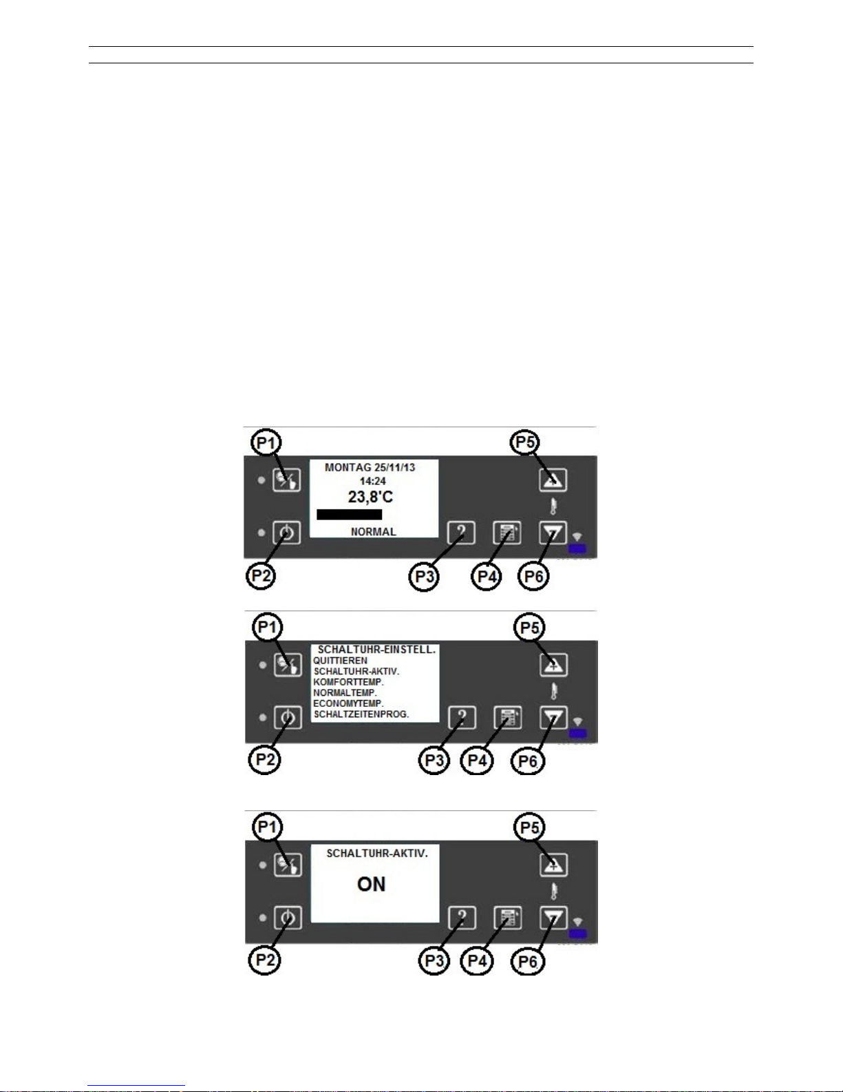
WP2-8_F 92 / 189
CONDITION DE STABILISATION
Après l’obtenion de la température minimale de 50°C, l’allumage s’éteint. Il faut attendre la
stabilité de flamme prescrite et l’augmentation de température de 3°C/minute. Cet état dure 180
secondes.
Si cette condition n’est pas satisfaite, la chaudière à pellet entre dans le statut d’allarme à
cause de la flamme irrégulière.
CONDITION DE FONCTIONNEMENT
A la température de 90°C du gas évacué, la chaudière allume le ventilateur.
FONCTIONNEMENT
La chaudière à pellet est mise en service.
TIMER (réglage du minuteur)
A l’aide de la fonction du minuteur, on peut programmer la chaudière pour une semaine.
(Chaudière on/off, réglage de la température: comfort, normale, économique).
Pour ouvrir le menu de réglage du minuteur, tenir appuyé le bouton P1 pendant 3 secondes.
Activation du réglage du minuteur: „SCHALTUHR-AKTIV.“ (P4, P5, P6 boutons).

WP2-8_F 93 / 189
Le LED L1 est allumé.
1.1. ARRIVÉE À LA VALEUR TEMPERATURE
La chaudière maintient la température réglée et après son obtention, elle garantit les meilleures
conditions pour l’utilisateur sans variations de puissances trop importantes, avec une
consommation minimale d’énergie.
Sur l’écran, la puissance est visualisée sous forme de diagramme. Il indique en même temps la
température ambiante.
REGLAGE DE LA TEMPERATURE
Le menu permet de régler trois température: COMFORT, NORMAL, ECONOMY.
Le réglage se fait dans les fenêtres de programmation.
L’exemple suivant montre le réglage de la température COMFORT:
Avec les boutons P5/P6, on peut augmenter ou réduire la température. Pour sauver la valeur,
tenir appuyé longuement le bouton P4.

WP2-8_F 94 / 189
1.2. REGLAGE DU MINUTEUR
A voir la figure suivante:
La figure montre les jours de la semaine. La rubrique DAY (jour) est divisée en 24 périodes, une
période dure une heure (1,2,….24). Les heures sont divisées en deux demi-heures.
Choix des fonctions et des planches d’heures
En appuyant sur les boutons P5 et P6, on peut se déplacer dans les deux direction sous les
symboles (heures, jours de la semaine, symbole de programmation „copy, add, exit“). On peut
choisir les heures désirées, par exemple 7:00 (à voir la figure).
TEMPERATURE LEVEL - NIVEAU DE TEMPERATURE
KOMFORT - COMFORT
NORMAL - NORMALE
ECO - ECONOMIQUE
TERMPERATURNIVEAU - NIVEAU DE TEMPERATURE
En tenant appuyé le bouton P4 (SET), on peut régler la colonne noire à la hauteur désirée (0
„AUS“, ECO, NORMALE, COMFORT).
Par exemple, la chaudière s’éteint (OFF) à 6:00 heures, à 6:30 s’allume en mode de
fonctionnement ECO, à 7:00 passe au niveau de puissance normal et à 7:30 fonctionne en
mode de fonctionnement COMFORT.
Les heures peuvent être réglées avec les boutons P5 et P6.
Modification des jours de la semaine
Avec les boutons P5 et P6, on peut régler les jours de la semaine. Pour cela, il faut appuyer sur
le bouton P4 (SET). Les jours de la semaine apparaissent l’un après l’autre.
Après la sélection du jour de la semaine, on peut régler les heures avec les boutons P5 et P6,
selon l’ordre déjà indiqué.
Pour tous les jours, on peut régler plusieurs activation et désactivation, et différentes valeurs de
température. La page suivante montre la copie des réglages d’un jour à un autre jour.
Copie du réglage d’un jour de la semaine:
On peut régler les dates avec les boutons P5 (avant) et P6 (retour), après passer au symbole
copy et farie la copie avec le bouton P4 (SET).

WP2-8_F 95 / 189
En appuyant sur le bouton P6 (retour), on peut retourner aux jours de la semaine et en
s’appuyant sur le bouton P4, choisir le jour où on veut copier les valeurs.
Avec le bouton P5 (avant), il faut passer au symbole Add et appuyer sur le bouton P4 (SET).
Cette opération peut être répétée pour chaque jour de la semaine où on veut copier les
réglages. Pour sortir de la fonction de copie, il faut passer avec les boutons P5 (avant) ou P6
(retour) au symbole exit et tenir appuyé le bouton P4 (SET).
Dans l’exemple de la figure:
La chaudière s’allume à 6:30 au niveau 3. (COMFORT).
A 12:00 heures, la chaudière s’éteint et reste dans cet état jusqu’à 17:30.
A 17:30 heures, la chaudière s’allume au niveau 1 (ECO).
A 18:00 heures, la chaudière change la puissance et passe au niveau 2 (NORMALE).
A 18:30 heures, la chaudière change la puissance et passe au niveau 3 (COMFORT).
La programmation est inefficace si la chaudière est éteinte (OFF) (LED en mode ON).
ATTENTION! La rubrique de programmation peut être activée, même si la chaudière est éteinte
(OFF), mais avec la rubrique de programmation, on peut commander la chaudière.
1.3. DESACTIVER LE MODE DE FONCTIONNEMENT AUTOMATIQUE
Par défaut, la chaudière fonctionne selon un mode AUTOMATIQUE de contrôle de puissance.
Cela veut dire que l’unité de commande ajuste automatiquement la puissance de chauffage de la chaudière pour
obtenir la température réglée. La différence entre la température réglée et la température ambiante détermine la
puissance optimale du dispositif.
Si le mode de fonctionnement AUTOMATIQUE est désactivé, l’utilisateur peut choisir entre 5 puissances prédéfinies:
L1 à peu près 2 - 2,3kW
L2 à peu près 4 - 4,3kW
L3 à peu près 6,5 - 6,9kW
L4 à peu près 7 - 7,2kW
L5 à peu près 7,2 - 7,5kW
La chaudière maintient son fonctionnement à la puissance choisie tant que la température ambiante n’arrive pas à
la valeur réglée.
Après avoir obtenu la température désirée, l’unité de commande passe à une plus petite puissance de chauffage.
Pour désactiver le mode AUTOMATIQUE, il faut effectuer les opérations suivantes:
Appuyer sur le bouton P4.
En appuyant sur le bouton P4, vous verrez le menu suivant:

WP2-8_F 96 / 189
A l’aide des boutons P5-P6, passer du mode ON (activé) au mode OFF (désactivé).
Pour sortir, appuyer deux fois sur le bouton P4.
Vous verrez le menu principal suivant, avec la puissance réglée:
Dans l’exemple suivant:
X: La température ambiante est de 20,2°C
Y: La chaudière fonctionne à la puissance de chauffage L1
Comment régler la puissance de chauffage?
Pour entrer dans le menu de réglage, appuyer sur le bouton P4.
La page visualise les informations suivantes:
X: Puissance de chauffage réglée
Y: Puissance de chauffage actuelle
La puissance de chauffage peut être augmentée avec le bouton P5, et diminuée avec la bouton P6.
Quelque temps après la modification, la chaudière passe à la nouvelle puissance réglée.
En appuyant sur le bouton P4, vous entrez sur la page de réglage de la température ambiante:

WP2-8_F 97 / 189
X: Température ambiante actuelle
Y: Température ambiante réglée
La température ambiante peut être réglée avec les boutons P5 et P6.
Pour retourner à la page principale, il faut appuyer de nouveau sur le bouton P4.
1.4. VIDER /REMPLIR LE RESERVOIR DE PELLETS
La consommation de pellets de la chaudière dépend de la puissance réglée. Il faut contrôler la quantité au moins
une fois par jour.
Si le réservoir se vide complètement, sur l’écran apparaît le message d’erreur „NoPellet”. Dans ce cas-là, il faut
appuyer sur le bouton P2 et remplir le réservoir. Le fonctionnement de l’appareil peut être relancé avec le bouton
P2.
Attention!
A la première mise en marche ou quand le réservoir se vide complètement, la chaudière nécessite plus de temps
pour le rallumage, car le système de dosage doit être rechargé.
Il peut arriver qu’il faut répéter l’opération de mise en marche. Dans ce cas-là, vous verrez sur l’écran „NoPellet”.
Ce message signifie qu’il faut répéter l’opération de mise en marche, en appuyant longuement et deux fois sur le
bouton P2. Si vous ne répétéz pas l’opération de mise en marche de la chaudière dans 15 minutes, vous recevrez
le message d’erreur F01 (allumage sans succès).
INSTRUCTION IMPORTANTE!
Avant la mise en marche, il faut vérifier que la boîte à feu soit complètement vide, elle doit être exempte de cendres et de pellets, car une boîte à feu bouchée peut causer des problèmes de fonctionnement.
Il est important de contrôler régulièrement la boîte à feu, durant le fonctionnement de l’appareil.
Nous vous conseillons de réaliser les contrôles dans les pauses de fonctionnement programmées.
ACTIVER /DESACTIVER LE SIGNAL SONORE „BEEP”:
Réglage par défaut: signal sonore „beep” OFF.
Pour l’activer, il faut faire les opérations suivantes:
Il faut déconnecter la chaudière.

WP2-8_F 98 / 189
1. Sur l’écran principal, appuyer longuement (3 sec) sur le bouton P3.
2. Vous verrez sur l’écran l’inscription suivante:
3. Appuyer tout de suite sur le bouton P1, sur l’écran le „BEEP” passe à ON:
Pour désactiver „BEEP”, il faut répéter ces trois opérations, et vous verrez l’écran suivant:
2. STAND-BY (DÉSACTIVATION)
Après l’activation du mode de fonctionnement STAND-BY et l’obtention de la valeur réglée (*),
la chaudière s’éteint et reste dans ce mode de fonctionnement.
5 minutes plus tard, quand la température dépasse la température ambiante de 2°C, la
chaudière passe au mode de fonctionnement STAND-BY.
Le mode STAND-BY est indiqué par la lampe LED (L2).
Dans ce mode, la chaudière fonctionne, mais passe à l’état actif seulement quand la
température ambienta diminue de 2°C, et reste dans cet état pendant 10 minutes au moins.

WP2-8_F 99 / 189
(*) quand la température ambiente est active.
2.1. CHAUDIÈRE ÉTEINTE
On peut éteindre la chaudière à n’importe quel moment avec le bouton P2 (ON/OFF).
Quand on éteint la chaudière, le LED vert flash jusqu’à l’arrêt complet;
ETAT ETEINT
Quand on appuye sur le bouton P2 (ON/OFF), la chaudière passe à l’état SWITCH OFF et
après, à l’état de refroidissement.
Le ventilateur de gas évacué passe à une plus grande puissance pour que tous les granulés
brûlent.
Le passage dans l’état suivant est possible quand la température du gas évacué ne dépasse
pas la valeur limite de 70°C.
REFROIDISSEMENT
Le ventilateur de gas évacué reste dans l’état allumé pendant 300 secondes.
Après le ventilateur de gas s’arrête (la lampe LED L2 est en état OFF).
INTERRUPTION D’ELECTRICITE
En cas d’interruption d’électricité de moins de 10 secondes, la chaudière continue à fonctionner.
Quand la chaudière est en mode de fonctionnement STAND-BY, elle se réallume dans le même
mode de fonctionnement. Dans tous les autres modes de fonctionnement, la chaudière s’éteint
en cas d’interruption de courant.
REDUCTION DE PRESSION (unité pneumatique)
Quand une réduction de pression non prévue se produit dans l’équipement, l’unité pneumatique
s’ouvre dans la phase de combustion et la chaudière passe à l’état “DEPRESSION“, où le
ventilateur de gas évacué augmente la puissance pour que l’unité pneumatique se ferme de
nouveau. Si le senseur de l’unité pneumatique reste ouverte pour plus de 20 secondes, la
chaudière passe à l’état d’allarme à cause de la réduction de pression.
ALLARME
En cas de message d’erreur, la chaudière passe à l’état d’allarme avec un retard de 60
secondes. Si l’allarme n’est pas annulée dans la période indiquée, la chaudière passe à l’état
d’allarme et s’éteint. Le ventilateur de gas évacué commence à fonctionner à la puissance
maximale.
Les états d’allarme sont enregistrés dans l’historique d’allarme, sauf l’état „pas de pellet”.

WP2-8_F 100 / 189
F01
il n’y a pas d‘allumage
le réservoir à pellet est vide, la qualité du
combustible est mauvaise
F02
la stabilisation ne se produit pas après l’allumage, il se produit peu de chaleur
F03
la température du gas évacué est trop basse
le réservoir à pellet est vide, la qualité du
combustible est mauvaise
F04
défaut de la température ambiente
F05
la température du circuit imprimé est trop élevée il faut laisser refroidir la chaudière
F06
il y a une trop grande différence de pression entre le
gas évacué et l’air du local
cheminée /conduite de gas évacué / chaudière
sales
F07
StB, température internet trop élevée il faut laisser refroidir la chaudière
F08
ventilateur de gas évacué
heminée /conduite de gas évacué / chaudière
sales, ventilateur défectueus
F10
le moteur Auger fonctionne pour plus de 40 secondes
F11
le senseur de l’interrupteur de pression se ferme à la
première révision
le courant est trop grande dans la cheminée, l’unité
pneumatique est défectueuse
F13
la température du gas évacué est trop élevée
2.2. L’ACCEPTATION DE L’ALLARME
En appuyant sur le bouton P2 (ON/OFF), on constate l’allarme, en appuyant longuement sur le
bouton P2 (ON/OFF), on éteint la chaudière.
S’il n’est pas possible d’arrêter la chaudière, il faut demander de l’aide.
Pendant le fonctionnement de la chaudière, il est interdire de retirer le câble de l’appareil
de la prise. Il faut d’abord éteindre la chaudière et attendre l’arrêt complet du ventilateur
(la combustion finale).
3. TENSION DU RÉSEAU / ALIMENTATION ÉLECTRIQUE
L’appareil doit être raccordé à une prise de courant, équipée de mise à la terre.
230 V AC/50 Hz (variation de tension autorisée: 195-255 V).
Il faut utiliser le câble de raccordement livré avec l’appareil.
Il faut faire attention à ce que le câble ne touche pas les surfaces chaudes de la
chaudière (conduite de gas évacué, etc).
Le câble de raccordement endommagé doit être changé sans tarder. Pour la commande
d’un câble de rechange, entrez en contact avec notre service clientèle.
 Loading...