


100 Kaminofen Bedienungs- und
D
GB
FR
I
HU
Aufstellanleitung
Fireplace user instruction
Cheminée mode d’emploi
Istruzioni per uso e installazione
Kandalló használati útmutató
TYP 10965 RH6F /
KAMINO TRENDY 6kW
TYP 10985 RH8F /
TYP 10985 RH8F Automatik /
KAMINO TRENDY 8kW
Vorwort
D
Sehr verehrter Kunde,
wir beglückwünschen Sie zum Erwerb unseres Kaminofens.
Sie haben die richtige Wahl getroffen.
Mit dem Kauf dieses Produktes haben Sie die Garantie für
• Hohe Qualität durch Verwendung bester und bewährter Materialien
• Funktionssicherheit durch ausgereifte Technik, die streng nach
der europäischen Norm EN 13240 geprüft ist
(Geräte sind für die Mehrfachbelegung geeignet)
• Lange Lebensdauer durch die robuste Bauweise
Damit Sie recht lange Freu de an Ihrem neuen Kaminof en haben, sollten Sie die
folgende Bedienungsanleitung studieren. Hierin finden Sie alles Wissenswerte,
sowie einige zusätzliche Ti pps.
Bei Ersatzteilbestellungen die am Typschild des Gerätes eingetragene
Artikel-Nr./Article No. und Fertigungs-Nr./Serial No. angeben.
ACHTUNG
Inhaltsverzeichnis
Vorwort ..........................................................................................................................2
Inhaltsverzeichnis ..........................................................................................................2
1. Bedienung ..................................................................................................................3
1.1 SICHERHEITSHINWEISE .......................................................................................3
1.2 Inbetriebnahme ........................................................................................................5
1.3 Außerbetriebnahme .................................................................................................7
1.4 Hinweise zum Heizen ..............................................................................................8
1.5 Reinigung und Pflege ..............................................................................................8
1.6 Störungsursachen, Behebung ...............................................................................10
2. Aufstellung ...............................................................................................................11
2.1 Vorschriften ............................................................................................................11
2.2 Aufstellräume .........................................................................................................11
2.3 Geräteabstände .....................................................................................................11
2.4 Schornsteinanschluss ........................................................................................... 12
3. Technische Daten ....................................................................................................14
3.1 Daten, Maßzeichnungen, Bilder ............................................................................14
2
1. Bedienung
D
1.1 SICHERHEITSHINWEISE
1. Die Geräte sind nach DIN EN 13240 geprüft (Typenschild).
2. Bei der Aufstellung und dem abgasseitigen Anschluss sind die anwendbaren
nationalen und europäischen Normen, örtliche und baurechtliche Vorschriften/Normen
(z.B. DIN 18896, DIN 4705, DIN EN 13384, DIN 18160, DIN EN 1856-2, DIN EN
15287 u.a.) sowie feuerpolizeiliche Bestimmungen (z.B. FeuVO) zu beachten. Lassen
Sie das Gerät nur von einem qualifizierten Fachmann aufstellen und anschließen. Zur
korrekten Funktion Ihres Gerätes muss der Schornstein, an den Sie das Gerät
anschließen wollen, in einwandfreiem Zustand und mind. bis 400°C belastbar sein.
3. Vor Erstinbetriebnahme und vor dem Schornsteinanschluss, die Bedienungsanleitung
gründlich durchlesen und den zuständigen Bezirksschornsteinfegermeister /
Bezirksbeauftragten informieren.
4. Zur einwandfreien Funktion des Gerätes muss der Schornsteinzug mind. 12 - 15 Pa
Unterdruck aufweisen und darf kurzzeitig
5. Es wird empfohlen bei Aufstellung der Geräte saubere Baumwollhandschuhe zu
tragen, um Fingerabdrüc ke, die später schwierig zu entfernen sind, zu vermeiden.
6. Im Interesse der Luftreinhaltung und der sicheren Funktion des Gerätes sollten di e in
der Bedienungsanleitung angegebenen max. Brennstoffaufgabemengen nicht
überschritten werden und die Türen der Geräte geschlossen sein, da s onst die Gefahr
des Überheizens besteht, was zu Beschädigungen am Gerät führen kann.
Beschädigungen solcher Art, unterliegen nicht der Garantiepflicht.
7. Die Türen der Geräte müssen während des Betriebes immer geschlossen sein.
8. Die zugelassenen Brennstoffe sind:
- Naturbelassenes Scheitholz (bis max. 33cm Länge)
- Braunkohlebriketts (siehe zulässige Brennstoffe in der Bedienungsanleitung)
9. Keine flüssigen Anzündhilfen verwenden. Zum anzünden sollten spezielle Anzünder
oder Holzwolle verwendet werden.
10. Die Verbrennung von Abfällen, Feinhackschnitzeln, Rinden, Kohlegruß,
Spanplattenresten, feuchtem und mit Holzschutzmitteln behandeltem Holz, Pellets,
Papier, Pappe o. ä. ist verboten.
11. Es ist darauf zu Achten, dass die Aufstellfläche ausreichend tragfähig ist. Bei
unzureichender Tragfähigkeit müssen geeignete Maßnahmen (z.B. Platte zur
Lastenverteilung) getroffen werden.
12. Beim ersten Anheizen könnte es zu Rauchentwicklung und Geruchsbelästigung
kommen. Unbedingt für gute Raumbelüftung sorgen (Fens ter und Türen öffnen) und
mindestens eine Stunde auf max. Nennwärmeleistung heizen. Sollte beim ersten
Heizvorgang die max. Temperatur nicht erreicht werden, so können diese
Erscheinungen auch später noch auftreten.
13. Die Bedienelemente und die Einstelleinrichtungen sind entsprechend der
Bedienungsanleitung einzustellen. Bitte benutzen Sie bei heißem Gerät die
Hilfswerkzeuge oder einen Schutzhandschuhe zur Bedienung.
14. Beim Öffnen der Heiztür kann es bei Fehlbedienung oder bei nicht ausreichendem
Schornsteinzug zu Rauchaustritt kommen. Es ist unbedingt zu beachten, dass die
Heiztür nur langsam, zuerst einen Spalt und nach ein paar Sekunden ganz geöffnet
werden darf. Außerdem soll vor dem Öffnen der Heiztür zum nachlegen von
Brennstoff nur noch das Glutbett im Brennraum vorhanden sein, dass heißt, es dürfen
keine Flammen mehr sichtbar sein.
18 Pa betragen.
3

15. Im Warmhaltefach und auf dem Gerät keine brennbaren Gegenstände abstellen.
16. Im Heizbetrieb können alle Oberflächen und besonders die Sichtscheiben sowie die
Griffe und Bedieneinrichtungen sehr heiß werden. Machen Sie während des
Heizbetriebes anwesende Kinder, Personen und Tiere darauf aufmerksam.
Verwenden Sie zur Bedienung den beigelegten Schutzhandschuh oder das
Hilfswerkzeug. Kinder und Jugendliche unter 16 Jahren dürfen den Ofen ohne
Aufsicht Erziehungsberechtigter nicht bedienen.
17. Achten Sie darauf, beim anzünden oder nachlegen von Brennstoff, keine leicht
entzündlichen Gegenstände am Körper zu tragen. Brandgefahr!
18. Es ist darauf zu achten, dass der Aschekasten immer bis Anschlag eingeschoben ist
und besonders darauf zu ac hten, dass keine heiße Asche entsorgt wird (Brandgefahr).
19. In der Übergangszeit kann es zu Störungen des Schornsteinzuges kommen, so dass
die Abgase nicht vollständig abgezogen werden. Die Feuerstätte ist dann mit einer
geringen Brennstoffmenge, am besten mit Holzspäne/-Wolle zu befüllen und unter
Kontrolle in Betrieb zu nehmen, um den Schornsteinzug zu stabilisieren. Der Rost
sollte sauber sein.
20. Nach jeder Heizperiode ist es angebracht, die Geräte durch einen Fachmann
kontrollieren zu lassen. Ebenfalls sollte eine gründliche Reinigung der Abgaswege und
der Abgasrohre erfolgen.
21. Wenn Aus besserungen oder Erneuerungen vorgenommen werden müssen, wenden
sie sich bitte rechzeitig unter Angabe der genauen Art.Nr. und Fert.Nr. an Ihren
Fachhändler. Es sind nur Original Wamsler - Ersatzteile zu verwenden.
22. Arbeiten, wie insbesondere Installation, Montage, Erstinbetriebnahme und
Servicearbeiten sowie Reparaturen, dürfen nur durch einen ausgebildeten
Fachbetrieb (Heizungs- oder Luftheizungsbau) durchgeführt werden. Bei
unsachgemäßen Eingriffen erlöschen Gewährleistung und Garantie.
23. Da der Festbrennstoff-Ofen/Herd die zur Verbrennung benötigte Luft dem
Aufstellungsraum entnimmt, ist dafür zu sorgen, dass über die Undichtheiten der
Fenster oder Außentüren stets genügend Luft nachströmt. Man kann davon
ausgehen, dass dieser durch ein Raumvolumen von mind. 4m³ je kW
Nennwärmeleistung gewährleistet ist. Ist das Volumen geringer, kann über
Lüftungsöffnungen ein Verbrennungsluftverbund mit anderen Räumen hergestellt
werden (min. 150cm²).
24. Es ist darauf zu achten, dass die Abstände zu brennbaren Bauteilen und Materialien -
seitlich, vorne und hinten- eingehalten werden. Diese Abstände entnehmen Sie der
Bedienungsanleitung oder dem Typenschild.
25. Die Feuerstätte darf nicht verändert werden, ansonsten verlieren Sie die Zulassung.
26. Der Anschluss an einem Schornstein, dessen wirksame Höhe unter 4m, bei
Mehrfachbelegung 5m liegt, sollte vermieden werden. An dem zum Anschluss des
Ofens vorgesehenen Schornstein dürfen höchstens zwei bis drei weitere Feuerstätten
angeschlossen sein. Es is t eine Berechnung nach EN 13384 notwendig.
27. Bei einem Schornsteinbrand verschließen Sie sofort alle Öffnungen am Gerät und
verständigen sie die Feuerwehr. Versuchen Sie auf keinen Fall selbst zu löschen.
Danach unbedingt den Schornstein vom Fachmann überprüfen lassen.
28. Festbrennstoffe erzeugen naturgemäß Ruß, ein Verschmutzen der Sichtscheibe ist
dadurch niemals völlig ausgeschlossen und stellt keinen Mangel dar.
29. Speck-, Natur-, Granit- und Sandsteine sind Naturprodukte. Daher sind
Farbabweichungen und Farbänderungen normal und kein Grund zur Reklamation.
4
1.2 Inbetriebnahme
Brennstoffart
Heizwert ca. kWh/kg
Hartholz
Braunkohlebriketts
4,0 – 4,2
5,3 – 5,5
Primärluft-
RH6F/RH8F
Primärluft-
Automat
Brennstoff-
Alle Type
Bild C
(max)
Scheitholz
Nennwärmeleistung
Nennwärmeleistung
Bild A
(min)
Braunkohlebrikett
Brennstoffe
Das Gerät ist ausschließlich für den Betrieb mit nachfolgend aufgeführten Brennstoffen
geeignet. Nur damit ist ein raucharmer und störungsfreier Betrieb gewährleistet.
Verwenden Sie nur naturbelassenes, trock enes Holz mit einer Restfeuchte von max. 20%
und Braunkohlenbriketts.
Bei den Geräten ist der Sekundärluftschieber / Brennstoffwähler an der Rück s eite montiert.
Bei Holz Schieber auf Stellung „H“, bei Kohle auf Stellung „K“ stellen.
Weichholz
Holzbrikett nach DIN 51731
Nicht zulässige Brennstoffe sind z.B.:
Die Verbrennung von Abfällen, Feinhackschnitzeln, Rinden, Spanplattenresten, Kohlegruß,
feuchtem oder mit Holzschutzmitteln behandeltem Holz, Pellets, Papier und Pappe o.ä. ist
verboten. Zum Anzünden sollte Holzwolle oder Grillanzünder verwendet werden.
Keine flüssigen Anzündhilfen verwenden!
Achtung!
Beim ersten Anheizen könnte es zu Rauchentwicklung und Geruchsbelästigung
kommen. Unbedingt für gute Raumbelüftung sorgen (Fenster und Türen öffnen) und
mindestens eine Stunde auf max. Nennwärmeleistung heizen. Sollte beim ersten
Heizvorgang die max. Temperatur nicht erreicht werden, so können diese
Erscheinungen auch später noch auftreten.
Mit dem Primärluftschieber können Sie innerhalb des Regelberei ches d ie Heizleistung en
einstellen.
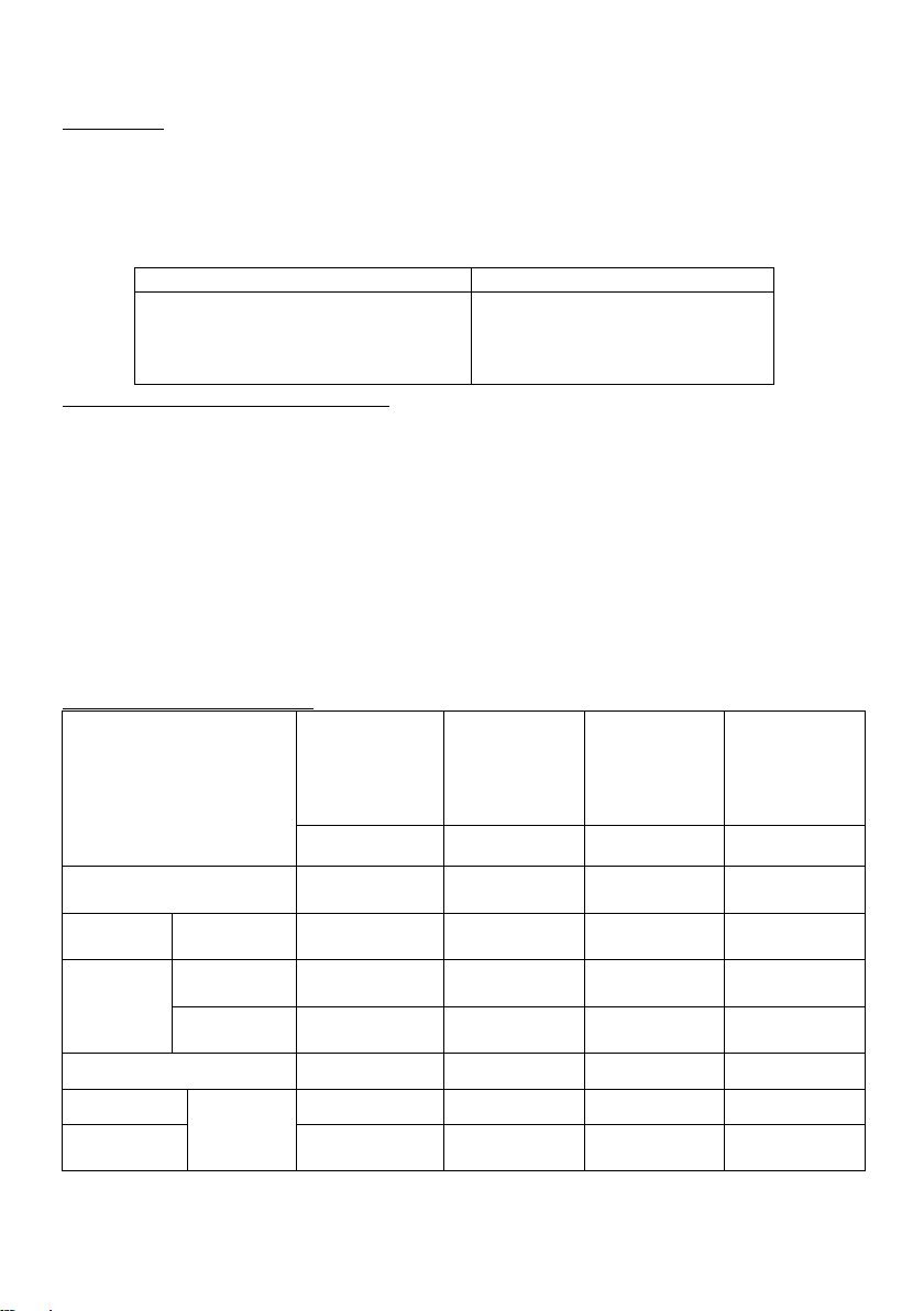
Verbrennungslufteinstellung:
Brennstoff
Anheizen
stellung
Tür unten Tür unten Rückwand
III
I Bild B H ca. 0,75 h
stellung
RH8F
4,3 – 4,5
5,0 – 5,2
wähler
Stellung
Sekundärluft
H
Brenndauer
-
Braunkohlebrikett
Außerbetriebnahme
Scheitholz
Dauerbrand -
Kochen
II Bild C K ca. 1 h
K ca. 4 h
0 Bild A K -
III - H III - K -
Tabelle 1
5
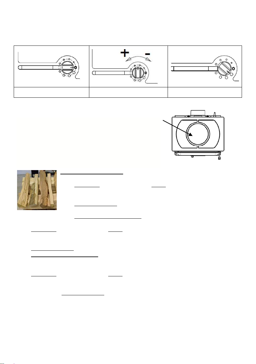
Gerät mit Automatik-Regelung
RH8F Automatic
Regelknopf (Primärluftstellung) nach Tabelle 1 einstellen.
Bild A (Min.) Bild B Bild C (Max.)
Der Regelknopf ist zwischen 0 und max. einstellbar (Bild „B”).
Kochen:
Das Gerät erfüllt die Kochprüfung der Herdnorm EN
12815.
Der Primärluftregler sollte zum Kochen nach Tabelle 1
„Kochen“ eingestellt werden und mit den unten angegebenen max. Brennstoffmengen betrieben werden.
Der Topf muss auf die vorgegebene Stelle der Kochplatte
gestellt werden (Bild). Überkochen und Fettspritzer sind zu
vermeiden.
Füllmengen / Anzünden:
RH6F 6 kW
NWL Scheitholz max. 1,4 kg, ca. 2-3 kleine Scheite pro Füllung,
bei Anzündvorgang Holz kreuzschlichten, Scheitholzlänge max. 33cm,
Durchmesser Ø 5 - 12 cm, Rundlinge spa lten , max. 1,9 kg/h
NWL Braunkohlebrikett
max. 1,7kg/h
NWL Holzbrikett nach DIN 51731 max. 1,2 kg, evtl. zerkleinern
max. 1,5 kg (ca. 2 Stk.) auf Grundglut auflegen,
RH8F 8 kW
NWL Scheitholz max. 1,9 kg, ca. 3-4 kleine Scheite pro Füllung, bei Anzündvorgang Holz
kreuzschlichten, Scheitholzlänge max. 33cm, Durchmesser Ø 5 - 12 cm, Rundlinge spalten,
max. 2,6 kg/h
NWL Braunkohlebrikett max. 2,2 kg (ca. 3 Stk.) auf Grundglut auflegen, max. 2,2 kg/h
NWL Holzbrikett nach DIN 51731 max. 1,6 kg, evtl. Zerkleinern
RH8F Automatic 8kW
NWL Scheitholz max. 1,9 kg, ca. 3-4 kleine Scheite pro Füllung, bei Anzündvorgang Holz
kreuzschlichten, Scheitholzlänge max. 33cm, Durchmesser Ø 5 - 12 cm, Rundlinge spalten,
max. 2,6 kg/h
NWL Dauerbrand Braunkohlebrikett max. 8,2 kg (ca. 15 Stk.) auf Grundglut aufleg en, max.
8,2 kg/4h
Die Brennstoffauflage aller Brennstoffe (bis auf Dauerbrand) muss einlagig erfolgen!
6

Erstes Anheizen:
Vor Inbetriebnahme sind evtl. Transportsicherungen im Gerät herauszunehmen und
Werbeaufkleber auf der Sichtscheibe oder der Verkleidung rückstands frei zu entfernen.
Die Heiztür und Aschentür öffnen durch Heben des Griffes nach oben (Bild 11). Bei
heißem Gerät ist dazu ein isolierter Schutzhandschuh zu benutzen. Den Primärluftschieber
Bild 10 (bei heißem Gerät ist dazu das Hilfswerkzeug zu benutzen Bild 15) entsprechend
der Tabelle 1 einstellen.
Legen Sie kleineres Anzündholz, kreuzgeschlichtet auf den freien Rost. Mit einen Kohleanzünder oder etwas Holzwolle von oben anzünden und Heiztür wieder verschließen.
Wenn das Feuer lebhaft brennt warten, bis eine Grundglut vorhanden ist, dann erneut
Brennstoff in geringen Mengen aufgeben, bis eine satte Grundglut vorhanden ist. Die max.
Brennstoffmengen sind zu beachten.
Kohleanzünder oder Holzwolle auf den Rost legen, darüber Holzspäne geben. Darauf
erst ein kleineres, dann größeres Holz geben, anzünden (Bild 12) und Heiz- und
Aschentür wieder verschließen. Wenn das Feuer lebhaft brennt und eine ausreichende
Grundglut vorhanden ist erneut Brennstoff aufgeben. Danach den Primärluftschieber
entsprechend der Tabe ll e 1 „Verbrennungslufteinstellung“ einstellen.
Das erste Anheizen sollte „sanft” verlaufen, mit geringer Menge Brennmaterial, damit
sich die Ofenteile an die Hitze gewöhnen können. Beim ersten Anheizen könnte es zu
Rauchentwicklung und Geruchsbelästigung kommen. Unbedingt für gute Raumbelüftung
sorgen (Fenster und Türen öffnen) und mindestens eine Stunde auf max.
Nennwärmeleistung heizen. Sollte beim ersten Heizvorgang die max. Temperatur nicht
erreicht werden, so können diese Erscheinungen auch später noc h auftreten.
Den Brennstoff nicht in den Brennraum einwerfen, sondern einlegen, da sonst die
Ausmauerung beschädigt werden kann.
Achtung!
Beim Öffnen der Heiztür kann es bei Fehlbedienung oder bei nicht ausreichendem
Schornsteinzug zu Rauchaustritt kommen. Es ist unbedingt zu beachten, dass die
Heiztür nur langsam, zuerst einen Spalt und nach ein paar Sekunden ganz geöffnet
werden darf. Außerdem soll vor dem Öffnen der Tür zum Nachlegen von Brennstoff
nur noch das Glutbett im Brennraum vorhanden sein, das heißt, es dürfen keine
Flammen mehr sichtbar sein.
1.3 Außerbetriebnahme
Türen schlieβen, Restglut ausbrennen Primärluftschieber in geschlossene – Stellung
bringen und Ofen abkühlen lassen.
Feuerraum und Aschenkasten bei kaltem Gerät reinigen und entleeren!
7

1.4 Hinweise zum Heizen
Der Festbrennstoff - Ofen darf nur mit geschlossener Fülltür (Heiztür) und Aschentür
betrieben werden.
Diese dürfen nur zum Anheizen, Nachlegen oder Reinigen des Feuerraums geöffnet
werden (evtl. Zugprobleme bei weiteren am Schornstein angeschlossenen Geräten).
Eine abgestimmt zugeführte Sekundärluft sorgt für die Nachverbrennung der im Abgas
enthaltenen brennbaren Bestandteile. Ein Verschmutzen der Scheibe kann aber bei
Festbrennstoffen nicht ausgeschlossen werden und stellt keinen Mangel dar. Dies
bedeutet eine rauch- und russ arme Verbrennung zur Schonung der Umwelt. Sollten Sie
Ihren Ofen in der Übergangszeit in Betrieb nehmen, dann prüfen Sie vorher den
Schornsteinzug, da dieser bei hohen Außentemperaturen sehr gering sein kann. Zu
diesem Zweck halten Sie ein brennendes Zündholz in die ein wenig geöffnete Heiztür.
Wenn die Flamme nicht deutlich angesaugt wird, ist zunächst ein sogenanntes Lockfeuer
zu erzeugen. Hierzu wird kurzzeitig Holzspäne/-Wolle im Ofen oder in der
Reinigungsöffnung des Schornsteins entzündet.
Der Rost (Bild 13) sollte vor jeder Brennstoffaufgabe gereinigt bzw. gerüttelt werden(wenn
vorhanden), um eine gute Verbrennungsluftzufuhr zu gewährleisten. Der Aschenkasten ist
regelmäßig im kalten Zustand zu entleeren (Bild 14). Bei noch heißem Gerät beiliegendes
Hilfswerkzeug verwenden. Bitte beachten Sie dabei, dass keine glühenden
Verbrennungsrückstände in die Mülltonne gelangen.
Es ist darauf zu achten, dass der Aschenkasten immer bis Anschlag eingeschoben
wird.
Achtung!
Im Interesse der Luftreinhaltung und dem Ofen sollten die angegebenen max.
Brennstoffaufgabemengen nicht überschritten werden, da sonst die Gefahr des
Überheizens besteht, was zu Beschädigungen am Gerät führen kann.
Beschädigungen solc her Art, unterliegen nicht der Garantiepflicht. Eine reduzierte
Heizleistung sollte nur durch Verringerung der Aufgabemenge und nicht durch
Reduzierung der Primärluft erfolgen.
Holztrocknung und -Lagerung
Holz braucht Zeit zum Austrocknen. Lufttrocken ist es bei richtiger Lagerung nach ca.
2 – 3 Jahren. Dazu einige Hinweise:
- Sie sollten das Holz gebrauchsfertig zersägt und gespalten lagern. Dadurch ist eine
rasche Trocknung gewährleistet, denn kleinere Holzstücke trocknen besser als Meterspalten.
- Ihr Scheitholz sollten Sie an einer belüfteten, möglichst sonnigen Stelle regenge-
schützt aufschichten (idealerweise Südseite).
- Lassen Sie zwischen den einzelnen Holzstößen eine Handbreite Abstand, damit
die entströmende Luft die entweichende Feuchtigkeit mitnehmen kann.
- Decken Sie Ihren Holzstoß keinesfalls mit Plastikfolie ab, sie lässt die Feuchtigkeit
nicht entweichen.
- Stapeln Sie frisches Holz nicht im Keller, da es dort wegen der geringen Luf tbewe-
gung eher fault, statt trocknet.
- Lagern Sie nur bereits trockenes Holz in trockenen Kellerräumen.
8

1.5 Reinigung und Pflege
Mit richtigem Betrieb/Bedienung und guter Pflege/Wartung erhöhen Sie die
Wertstabilität und Lebensdauer Ihrer Geräte. Sie sparen wertvollen Ressourcen und
schonen unsere Umwelt und Ihren Geldbeutel.
Achtung:
Nach jeder Heizperiode ist es angebracht, den Ofen gründlich zu kontrollieren und zu
reinigen. Wenn Ausbesserungen oder Erneuerungen vorgenommen werden müssen,
wenden Sie sich bitte rechtzeitig unter Angabe der Artikel-Nr. und der F.-Nr. (siehe
Typschild) an Ihren Fachhändler.
Reinigen Sie Ihre Sichtscheibe vor der ersten Benutzung mit einem feuchten sauberen
Tuch. Verreiben Sie danach eini ge Tropfen eines Pflegemittels für Glaskeramik Scheiben
mit einem Küchenpapier auf beiden Seiten der Scheibe. Es dürfen keine
Putzmittelrückstände zwischen der Scheibe und der Dichtung gelangen.
Nach dem Nachwischen und Trockenpolieren ist die hochwertige Oberfläche mit einem
unsichtbaren Film überzogen, dieser hilft die Scheibe sauber zu halten und erleichtert bei
regelmäßiger Wiederholung die Reinigung.
Festbrennstoffe erzeugen naturgemäß Ruß, ein Verschmutzen der Sichtscheibe ist
dadurch niemals völlig ausgeschlossen und stellt keinen Mangel dar.
Pflege von Nasslack, Email- und Pulverbeschichtungen: Die Pflege der äußeren
Flächen ist nur bei kaltem Ofen zu empfehlen. Die lackierten Flächen sollten nur mit
klarem Wasser, vorsichtig und mit einem leicht befeuchteten weichen Tuch gereinigt
werden (nicht scheuern). Vorab an einer nicht sichtbaren Stelle das Lackverhalten teste n.
Bei email- und pulverbeschichteten Flächen kann in besonderen Fällen vorher mit
Seifenlauge oder etwas Geschirrspülmittel behandelt und dann leicht trocken gerieben
werden.
Pflege von Keramik- und Glasverkleidungsteilen: Schmutz und Fett kann mit Seife und
Wasser entfernt werden.
Pflege von Speckstein und Sandstein: Speck- und Sandstein ist ein Naturstein, daher
sind Farbabweichungen und Farbänderungen normal und kein Grund zur
Reklamation! Schmutz und Fett kann mit Seife und Wasser, kleine Kratzer mit
Nassschleifpapier (Körnu ng 240) ent fer nt werden.
Achtung: Auf keinen Fall sollten Sie bei der Pflege Schwämme, Scheuermittel,
aggressive oder kratzende Reinigungsmittel verwenden!
Arbeiten, wie insbesondere Installation, Montage, Erstinbetriebnahme und
Servicearbeiten sowie Reparaturen, dürfen nur durch einen ausgebildeten Fachbetrieb
(Heizungs- oder Luftheizungsbau) durchgeführt werden. Bei unsachgemäßen Eingriffen
erlöschen Gewährleistung und Garantie.
9
1.6 Störungsursachen, Behebung
Art der Störung
mögliche Ursache
Behebung
Geruchbildung:
Austrocknung der
Den Ofen ents prec hend d er
Leistung heizen .
angewendeten Schutzfarbe.
Verdampfung von Ölresten
Zu geringe Wärmeabgabe:
Bei ungenügender Reinigung des Schornsteins, bei falsc hem Brennstoff (z. B. zu
feuchtes Holz) oder falscher Verbrennungslufteinstellung kann es zu einem
Schornsteinbrand kommen. Schließen sie in so einem Fall die Verbrennungsluft an
der Feuerstätte und rufen Sie die Feuerwehr.
• Geräteleistung zu klein
gewählt.
• Zu geringer
Schornsteinzug
• Zu langes und undichtes
Abgasrohr
• Undichtheiten an der
Glas-/Heiz-/Aschentür
• Verbrennung von zu
feuchtem Holz
Maßnahmen bei Schornsteinbrand
Niemals selber versuchen mit Wasser zu löschen.
Bedienungsanle it ung me hrere
Stunden in Kleins tel lun g
betreiben. Danach f ür m ehr er e
Stunden auf m axi mal e
• Lassen Sie Ihren Wärmebedarf vom Fachmann
kontrollieren.
• Der erforderliche Schornsteinzug muss mind. 12 Pa
und darf kurzzeitig max. 18
Pa haben. Kontrollieren Sie
Ihren Schornstein auf
Dichtheit. Die Türen anderer
an diesen Schornstein angeschlossenen Feuerstätten
dicht verschließen. Vor
allem auf undichte
Schornstein- bzw.
Reinigungsverschlüsse
achten. Eventuell mit
senkrechter Anlaufstrecke
anschließen.
• Die gesamten Abgasrohrverbindungenen müssen gut
abgedichtet sein und feuerfest gedämmt werden.
• Dichtung kontrollieren,
Türen gut verschließen.
Eventuell Dichtschnur
erneuern lassen.
• Nur gut getrocknetes Holz
verwenden.
10

2. Aufstellung
Typ
hinten
seitlich
vor dem Gerät
Typ 10965 RH6F 6kW
25 cm
45 cm
100 cm
Typ 10985 RH8F 8kW
30 cm
50 cm
100 cm
Typ 10985 RH8F Automatic 8kW
30 cm
30 cm
80 cm
2.1 Vorschriften
Bei der Aufstellung und dem abgasseitigen Anschluss sind die anwendbaren nationalen
und europäischen Normen, örtliche und baurechtliche Vorschriften/Normen (z.B. DIN
18896, DIN 4705, DIN EN 13384, DIN 18160, DIN EN 1856-2, DIN EN 15287 u.a.) sowie
feuerpolizeiliche Bestimmungen (z.B. FeuVO) zu beachten. Lassen Sie das
Gerät nur von einem qualifizierten Fachmann aufstellen und anschließen. Zur korrekten
Funktion Ihres Gerätes muss der Schornstein, an den Sie das Gerät anschließen wollen, in
in einwandfreiem Zustand und mind. bis 400°C belastbar sein.
2.2 Aufstellräume
Da der Kaminofen die zur Verbrennung benötigte Luft dem Aufstellungsraum entnimmt, ist
dafür zu sorgen, dass über die Undichtheiten der Fenster oder Außentüren stets genügend
Luft nachströmt. Man kann davon ausgehen, dass dieser durch ein Raumvolumen von
mind. 4m³ je kW Nennwärmeleistung gewährleistet ist. Ist das Volumen geringer, kann
über Lüftungsöffnungen ein Verbrennungsluftverbund mit anderen Räumen hergestellt
werden (min. 150cm²).
2.3 Geräteabstände
Alle brennbaren Bauteile, Möbel oder auch z.B. Dekostoffe in der näheren Umgebung des
Ofens sind gegen Hitzeeinwirkung zu schützen.
Einrichtungsgegenstände im Strahlungsbereich
Im Sichtbereich (Strahlungsbereich) des Feuers muss zu brennbaren Bauteilen, Möbel
oder auch z.B. zu Dekostoffen ein Abstand von mindestens 80 / 100 cm (Tabelle 2),
gemessen ab Vorderkante Feuerraumöffnung eingehalten werden. Der Sicherheitsabstand
reduziert sich auf die Hälfte, wenn ein belüfteter Strahlungsschutz vor das zu schützende
Bauteil montiert wird.
Einrichtungsgegenstände außerhalb des Strahlungsbereichs
Die Stellwände seitlich und hinter dem Gerät dürfen nicht aus brennbaren Baustoffen
hergestellt, oder mit brennbaren Baustoffen verkleidet sein, sofern der Abstand von der
Tabelle 2 seitlich und hinten unterschritten wird.
Der Seitenabstand zu Möbelteilen aus Holz oder Kunststoff muss ebenfalls den der
Tabelle 2 mindestens betragen.
Tabelle 2
Boden vor dem Ofen
Fuβböden aus brennbarem Material, wi e Teppich, Parkett oder Kork, müss en unter dem
Ofen sowie von der Feuerraumöffnung gemessen 50 cm nach Vorne und 30 cm seitlich
durch einen Belag aus nicht brennbaren Baustoffen, z.B. Keramik, Stein, Glas oder einer
Bodenplatte aus Stahl, ersetzt oder geschützt werden.
11
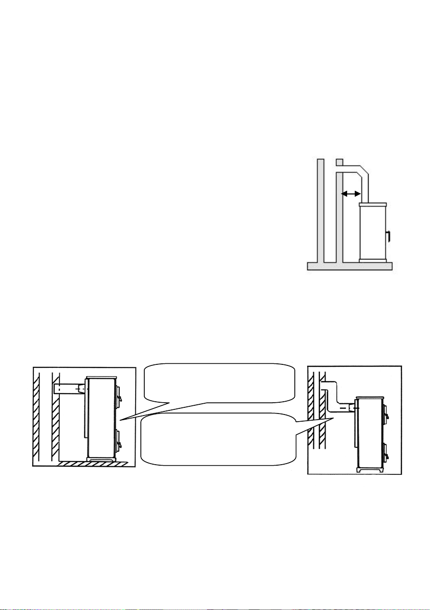
2.4 Schornsteinanschluss
X
Bei geringem Schornsteinzug sollte
werden.
In der Regel kann der Ofen mit
ACHTUNG:
Vor dem Anschluss des Gerätes ist in jedem Fall der zuständige BezirksSchornsteinfegermeister zu R ate zu ziehen!
Verbindungsstücke müssen am Gerät und untereinander fest und dicht verbunden sein.
Sie dürfen nicht in den freien Schornsteinquerschnitt hineinragen. Das Verbindungsstück
zwischen Kaminofen und Schornstein soll den gleichen Querschnitt haben wie der
Rohrstutzen am Ofen. Waagerechte Verbindungsstücke über 0,5 m sollen zum
Schornstein hin um 10 Grad anstei gen. Rohre, die nicht wärmegeschützt oder senkrecht
geführt sind, sollen nicht länger als einen Meter sein.
Es sind die Forderungen der Feuerungsverordnung (FeuVO),
die jeweiligen Länderbauordnungen sowie für den Schornstein
die DIN 18896, DIN 4705, DIN EN 13384, DIN 18160 und der
DIN EN 15287 zu beachten.
Verbindungstücke müssen nach DIN EN 1856-2 geprüft sein.
Das Maß X (Abstand zu brennbaren Baustoffen/Materialien)
muss nach Angaben des Herstellers des Verbindungsstückes
eingehalten werden.
ACHTUNG:
Der Anschluss an einem Schornstein, dessen wirksame Höhe unter 4m, bei
Mehrfachbelegung 5m liegt, sollte verm ieden werden / Daten zur Schornsteinberechnung /
Kapitel 3. /
An dem zum Anschluss des Ofens vorgesehenen Schornstein dürfen höchstens zwei bis
drei weitere Feuerstätten angeschlossen sein.
einem Rohr direkt an den
Schornstein angeschlossen werden.
der Ofen durch ein Senkrechtes
Abgasrohr, das als Anlaufstrecke
dient, mit dem Schornstein verbunden
12
13
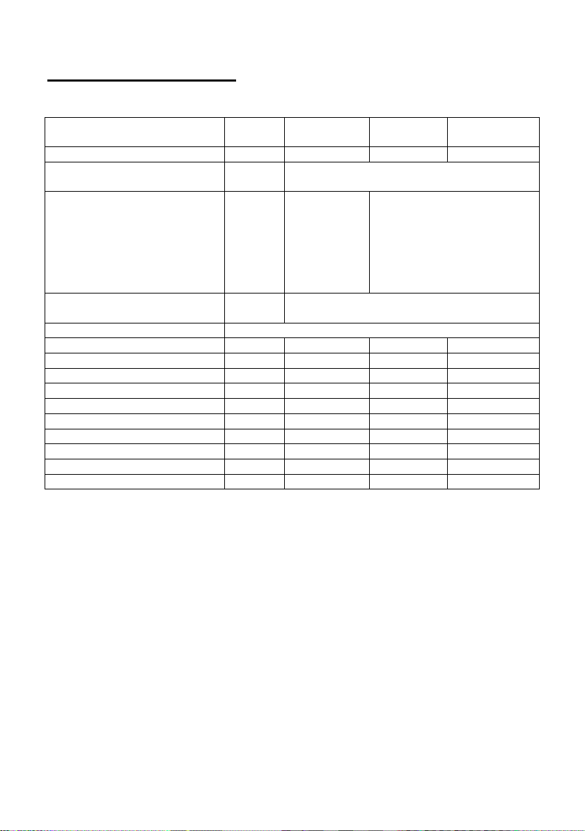
3. Technische Daten
Typen:
109 65
RH6F
109 85
RH8F
109 85 RH8F
AUTOMATIC
Nennwärmeleistung
kW 6 8
8
Ø
mm
Raumheizvermögen bei
Zeitheizung
min. Förderdruck bei
Nennwärmeleistung
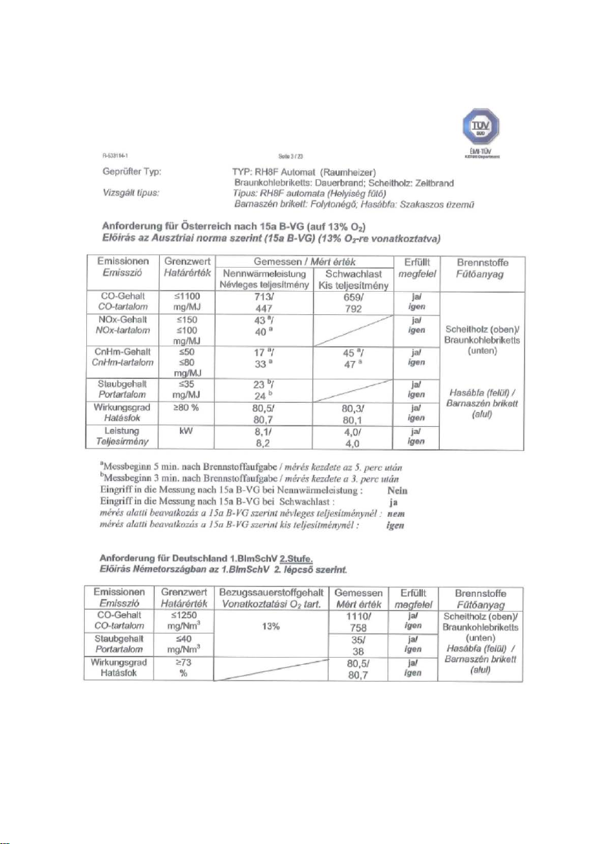
Abgaswerte
Scheitholz und BB 7“ (Braunkohlebriketts
Abgasmassenstrom
g/s
5,4 / 6,2
6,6 / 7,2
7,3 / 5,8
Abgasstutzentemperatur
°C
363 / 384
353 / 366
317 / 330
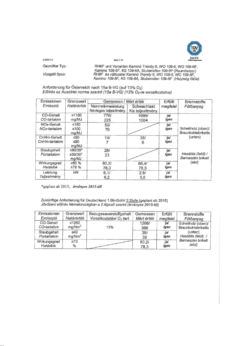
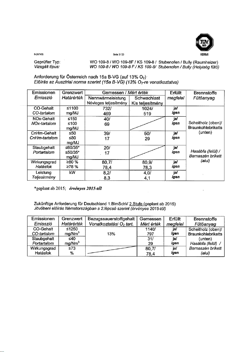
CO (bezogen auf 13% O2)
mg/Nm³
1208 / 386
1140 / 797
1110 / 758
CO (bezogen auf 13% O2)
%
0,096 / 0,03
0,09 / 0,06
0,09 / 0,06
CO
mg/MJ
776 / 226
732 / 469
713 / 447
Staub (bezogen auf 13% O2)
mg/Nm³
35 / 39
31 / 29
35 / 38
Staub
mg/MJ
28 / 23
20 / 17
23 / 24
OGC
mg/MJ
14 / 7
39 / 17
17 / 33
Wirkungsgrad
%
80,2 / 78,3
80,7 / 78,4
80,5 / 80,7
Gewicht Netto ca.
kg
85
109,5
148
3.1 Daten, Maßzeichnungen, Bilder
Abgasanschluss hi nten
günstigen/weniger günstigen/ungünstigen Heizbedienungen nach DIN
18893/Tab2 bei
Dauerheizung
m³ 115/68/45 182/105/71
Pa 12
120
Alle Angaben der Abgaswerte beziehen sich auf die EN 13240 unter stationären
Laborbedingungen
14
4
1
5
7
12
13
10
9
11
3 8 2
11
6
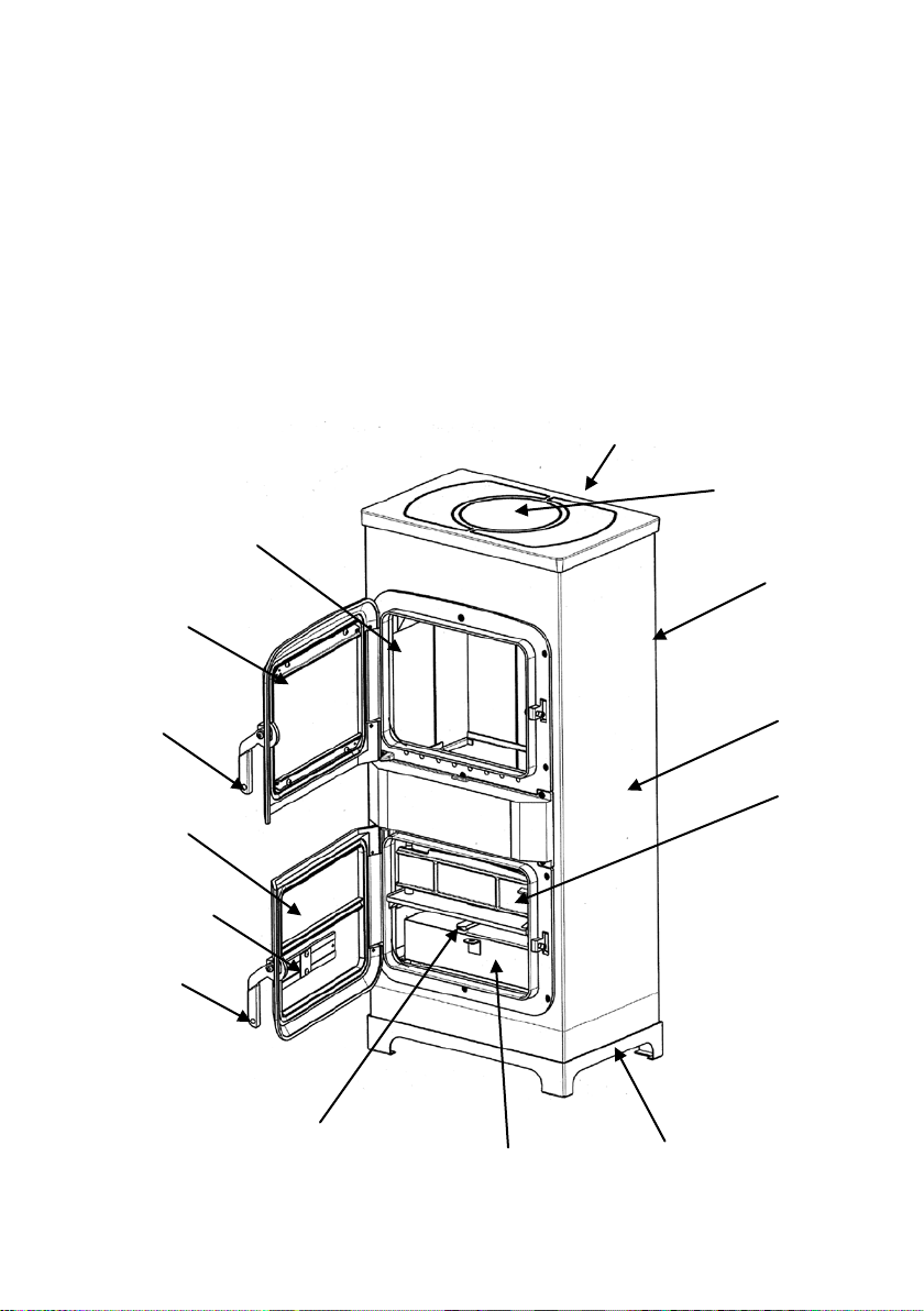
LEGENDE ZU DEN BILDERN
1. Gusskochplatte
2. Heiztür mit Sichtfenster
3. Aschentür
4. Abgasstutzen hinten
5. Brennstoffwähler / Sekundärluftregler (Bild 9)
6. Primärluftregler (Bild 10)
7. Korpus emailliert
8. Schamotteverkleidung im Feuerraum
9. Rüttelrost (innen) (Bild 13)
10. Aschekasten
11. Heiztür- und Aschetür Griff
12. Rosttür (nur 8kW)
13. Sockel
15
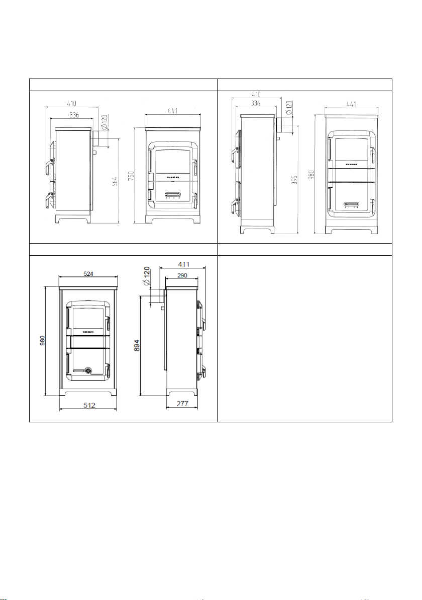
Bild 1: RH6F 6kW
RH6F 6kW
RH8F 8kW
RH8F Automatic
Bild 2: RH8F 8kW
Bild 3: RH8F Automatic 8kW
16
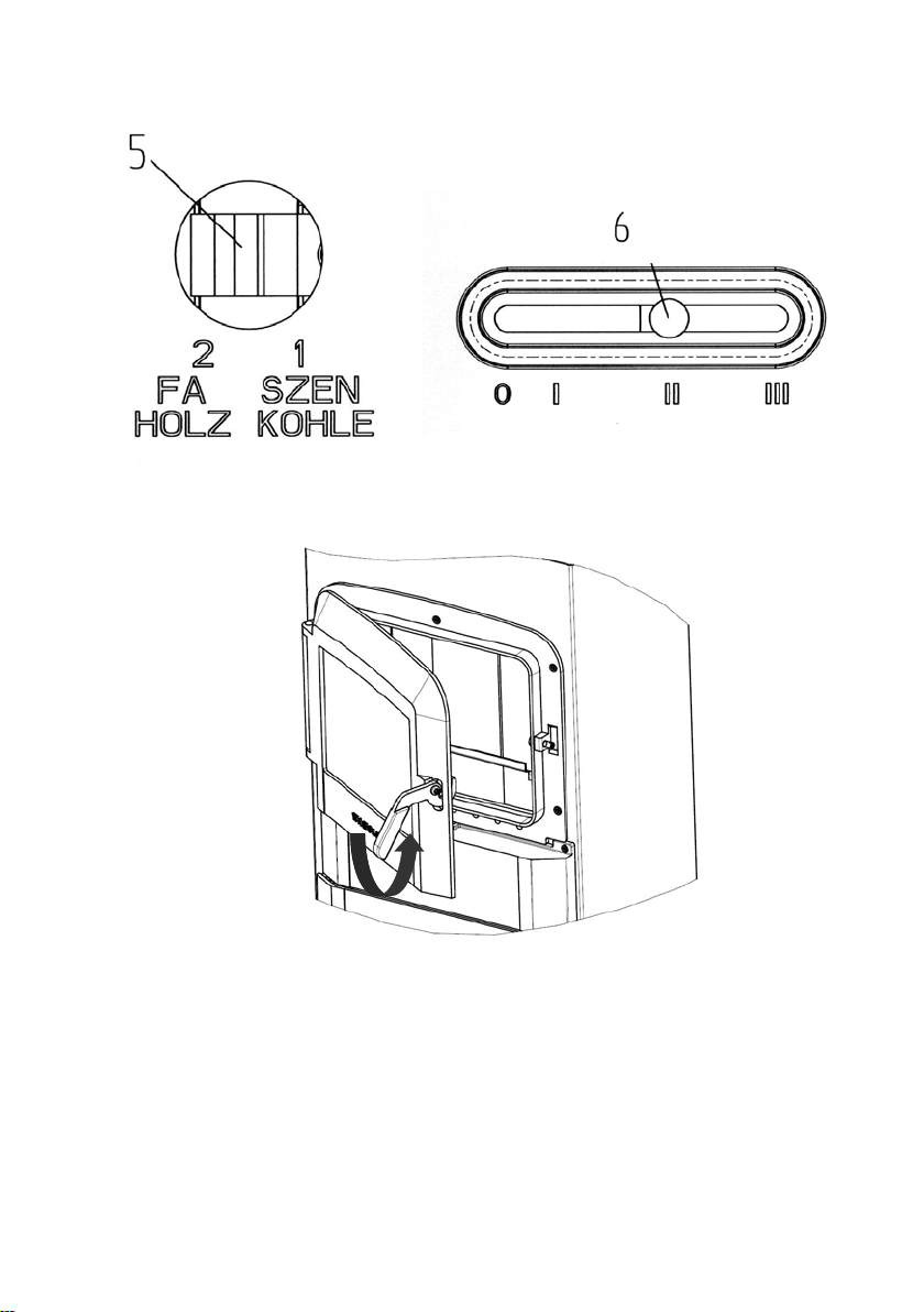
Bild 9
Bild 10
Bild 11
17
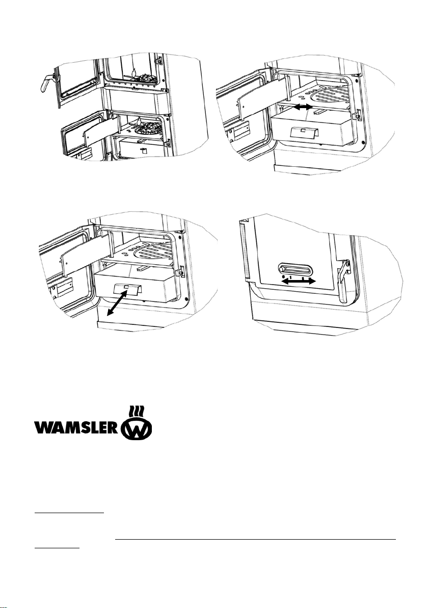
Bild 12
Bild 13
Bild 14
Bild 15
Die angeführten Abmessungsangaben sind nur zur Information! Wir behalten uns
das Recht von Konstruktionsänderungen vor, falls diese das technische Niveau
erhöhen, oder die Qualität verbessern!
Haus – und Küchentechnik GmbH
Adalperostr. 86
D – 85737 Ismaning
Telefon +49 (0)89 32084-0
Telefax +49 (0)89 32084-294
www.wamsler.eu
Änderungen, die dem technischen Fortschritt dienen und / oder einer Qualitätsverbesserung bewirken,
behalten wir uns vor.
übernehmen.
Für Druckfehler und Änderungen nach Drucklegung können wir keine Haftung
18
19
20 21 22 23 24 25
GB
Foreword
PLEASE NOTE:
Dear Customer!
Thank you for choosing our product!
By purchasing this product you receive guarantee for
• good quality originating from the usage of the finest and proven materials,
• operating security which is controlled acc ordi ng to German and European
norms (Corresponds to the standards EN 13240)
• long life ensured by the robust structure.
In order to be able to use your new fireplace for a long time please re ad the
following instructions manual. You will find all the necessary information in it
and some additional advice.
When ordering replacement parts, the Article No. and Serial No. shown on the
identification plate must be quoted.
Contents
Foreword ..................................................................................................................... 23
Contents ...................................................................................................................... 25
1.1 SAFETY INSTRUCTIONS ..................................................................................... 26
1.2 Installation ............................................................................................................. 28
1.3 Putting out of operation ......................................................................................... 30
1.4 Heating instructions ............................................................................................... 30
1.5 Cleaning and maintenance .................................................................................... 31
1.6 Potential problems and how to tackle them ........................................................... 32
2. Placing ..................................................................................................................... 33
2.1 Prescriptions .......................................................................................................... 33
2.2 Place of installation ................................................................................................ 33
2.3 Distances ............................................................................................................... 33
2.4 Connection of the fireplace .................................................................................... 34
3. Technical specification ............................................................................................ 36
3.1 Data, dimensional drawings, pictures .................................................................... 36

GB
1. Usage
1.1 SAFETY INSTRUCTIONS
1. The stoves are tested to EN 13240 (see identification plate).
2. For installation and for flue gas connections, the requirements of the Fire Regula-
tions (FeuVO in Germany) apply, as well as local building regulations such as the
following technical standards DIN 18896, DIN 4705, EN 13384, DIN 18160, EN
1856-2 and EN 15287. In order for the stove to function correctly the chimney to
which you want to connect the stove must be in good condition.
3. Before first use and before connecting to the chimney, you must read the Instructions for Use carefully and inform the local authority responsible for approving heating systems.
4. While installing the stove you are recommended to wear clean cotton gloves, in
order to avoid leaving fingerprints which can be difficult to remove afterwards.
5. In the interests both of clean air, and of the safe functioning of the stove, the fuel
quantities listed in the Ins tructions for Use should never be exceeded, and the doors
of the stove must be shut during use to avoid the risk of overheating, which can lead
to damage to the stove. Damage due to this cause is not covered by the guarantee.
6. The stove doors must remain shut at all times while the stove is in use.
7. Permitted fuels are:
- Natural chopped firewood (up to 33 cm max. in length)
- Lignite (brown coal) briquettes (see permitted fuels in the Instructions for Use)
8. Never use liquid fire starters. Use either special firelighters or wood shavings.
9. Burning rubbish, fine chips, bark, coal slack, chips from planing, damp wood or
wood treated with preservative, paper, cardboard or similar is not permitted.
10. The first time the stove is heated there may be some smoke and an unpleasant
smell. Make sure that the room is well ventilated (open windows and doors) and
heat for at least an hour at the maximum nominal heat load. If the maximum temperature is not reached the first time the stove is heated, then there may be further
unpleasant smells at a later date.
11. All controls and settings must be used as indicated in the Instructions for Use.
When the stove is hot, please handle only using the implements or protective gloves
provided.
12. If the stove is not working correctly, or if the chimney is not drawing properly, smoke
may appear when the fire door is opened. It is very important to only open the fire
door slowly, initially jus t a crack, then wait a few seconds before opening fully. In
addition, before opening the fire door to top up the fuel, make sure that only glowing
material is present: there must not be any visible flames.
13. Do not place any flammable items in the warming drawer or on the surface of the
stove.
14. When in use, all surfaces and particularly the glass doors and handles and other
controls can become very hot. Make chi ldren, young people, older people and animals aware of this danger, and keep them away from this source of heat when the
26

stove is being used. Use the protective gloves or the implements provided. Children
and young people under 16 must not use the stove unless supervised by an adult
who is responsible for them.
15. Make sure that the ash pan is always fully pushed in, until it touches the back.
Never remove ashes while still hot (fire risk).
16. In spring and autumn the chimney may no longer draw correctly, so that gases
produced by combustion are not completely removed. The fire chamber should then
be filled with a small quantity of fuel, ideally with wood shavings, and lit under supervision, in order to stabilise the chimney draught. The grate must be clean.
17. After each prolonged period of use for heating, have the stove checked by a professional. The flues and pipes for the evacuation of fumes must also be thoroughly
cleaned.
18. If repairs or replacements are necessary, please contact your supplier with the
necessary article numbers and serial numbers in good time. Only original WAMSLER replacement parts may be used.
19. Work such as installation, setup, commissioning and services, as well as repairs,
must only be carried out by qualified personnel (heating system or space heating
technicians). Intervention by non-qualified persons invalidates the warranty and
guarantee.
20. As the solid fuel oven/stove draws the air required for combustion from the surrounding room, you must ensure that sufficient air can be drawn in through nonsealed windows and outside doors. It can be assumed that is this is provided by a
room volume of at least 4 m³ per kW nominal heat capacity. If the volume is less
than this, then air vents can be used to provide access to further air in other rooms
(min. 150 cm²).
21. You must ensure that the correct safety distance is maintained from all flammable
components and materials – to the side, rear and front. These distances can be
found in the Instructions for Use or the identification plate.
22. The fire chamber must not be modified.
23. Connection to a chimney whose functional height is less than 4 m, or if multiple
stoves are installed, 5 m, is not permitted. A maximum of two other fires can be
connected to the chimney which is to be connected the stove.
24. If the chimney catches fire immediately c lose all doors and openings and call the
fire brigade. Do not attempt to extinguish the fire yourself. Afterwards have the
chimney thoroughly check ed out by a professional.
25. Solid fuels naturally create soot, so it is always possible that the window glass will
become dirty: this does not mean there is a malfunction.
27
1.2 Installation
Heating value appr.
kWh/kg
Hard wood
Brown-coal
4,0 – 4,2
5,3 – 5,5
primary air
RH6F/ RH8F
Setting of the
All types
primary air
matic
door down
backside
door down
Nominal heat-
ance
Nominal heat-
ance
Putting out of working
order
Wood
Cooking
III H -
Browncoal
K
-
Fuels
The equipment can be used with fuels detailed in the followings. This way the “lowsmoke” and trouble-free operation can be secured. Use only dry wood with moisture of maximum 20% and lignite briquette.
Types of fuels
Soft wood
Wood briquette after DIN 51731
4,3 – 4,5
5,0 – 5,2
Filling quantities RH6F 6kW Filling quantities RH8F 8kW
- Split billet: max. Length: 33 cm - Split billet: max. Length: 33 cm
max. two billets per filling, appr. 1.4 kg max. two billets per filling, appr. 1.9 kg
- Lignite briquette: max. 1.5 kg - Lignite briquette: max. 2.2 kg
Filling quantities RH8F Automatic 8kW
- Split billet: max. Length: 33 cm max. two billets per filling, appr. 1.9 kg
NWL endurance burning, lignite briquettes max. put in 8.2 kg (15 pcs.) on glowing embers, max. 8.2 kg / 4h
Adjustment of the burning air:
Fuel
regulator
fuel selector
regulator
RH8F Auto-
Warming up, kindling III H Pic. “C”
Wood
ing perform-
I H Pic. “B”
Browncoal
Slow-burning - K Pic. “A”
ing perform-
II K Pic. “C”
0 K Pic. “A”
Table 1
28

Device control with the automatic control RH8F Automatic
Pic. A (Min.)
Pic. B
Pic. C (Max.)
The primary regulator knob on ash door, to be set in accordance with Table 1
Between 0 and up to the mark infinitely adjustable control knob to the desired
performance.
Cooking:
The device meets the test of cooking stove EN 12815.
The primary air control should be set according to Table 1
for cooking "cooking" and with the maximum specified
below. Amounts of fuel to operate. The pot must be set to
the predetermined location of the hot plate (Fig.). Avoid
overcooking and fat splashes.
IT IS NOT ALLOWED to burn waste, fine chipping, bark, wood handled with preventive chemicals, furthermore paper and cardboard. For kindling please use wood
scrapings or grill starter but never use liquid auxiliaries!
The first kindling
At the first fire set-up could be a little smoke, but is not dangerous, normal!
In this time, please ventilate the room carefully!
Warning! Upon the firs t kindling, s moke and unplea sant smell ma y be generated. Always ensure the proper ventilation of the room (by opening windows
and doors), and heat the fireplace at maximum rated heating performance. If
with the first heating the maximum temperature is not reached, the abovementioned effects may as well arise later on.
• Before installation pull out the delivery securer off the refractory brick
through the furnace chamber.
Open the door by raising the handle (Picture 11). If the equipment is hot, you can
use insulated gloves. Adjust the primary air regulator (Picture 10), secondary air
regulator and the fuel switch according to the Table 1. Put coal lighter or wood wool
onto the fire grate, followed by wood chips. First insert small piec es of wood, and
then larger ones, light them (Picture 12) and close all the doors again. W hen the
wood burns quickly, and leaves sufficient glowing embers, put additional fuel on the
fire. Thereafter, adjust the air regulators and the fuel switch according to the Table
1 („Adjustment of the burning air”). The first kindling should be performed “finely”
29

with little fuel only, so that the parts of the fireplace are adapted to heat. During the
first kindling, the generation of smell is normal and absolutely undangerous.
1.3 Putting out of operation
• Let the glowing ember burn to ashes and the fire-place get cold.
• Empty the furnace chamber and the ash bin.
• Close the doors, and shut off all air regulators (position 0) and the fuel switch
(position K)
1.4 Heating instructions
The fireplace should be operated only with closed furnace chamber door. These
doors may be opened only for kindling, loading or when cleaning the furnace
chamber (otherwise draught problems may occur with other equipment connected
to the same chimney).
Warning!
When opening the furnac e chamber door, any incorrect handling or insufficient draught may induce smoke. Always ensure that the furnace chamber
door may be opened only slowly, first just to a small extent, and then fully
after a few seconds. In addition, if you intend to put additional fuel i nto the
fire, before the ope ning of the door only there ma y be only ember bed in the
burning space, i.e. no flames may be visible.
Led into the burning space in correspondence with the existing conditions, the secondary air provides for the follow-up burning of the combustible components of in
the burning space. This in fact means smoke and soot-poor burning, which contributes to the protection of the environment. If you wish to commission the fireplace in
a transitional period, please, please first examine the chimney draught, as it can be
especially weak at high external temperatures. Towards this end, hold a burning
match in the slightly opened feeding door. If the flame is not drawn significantly by
the draught, then a so-called starting fire is to be set first. Towards this end, burn
wood chips/wool in the fireplace or the cleaning hole of the chimney. The fire grate
is to be cleaned before every kindling to ensure the proper inflow of air for burning.
The ashtray is to be emptied regularly. Should the equipment be extremely hot, use
the gloves provided. Please, be careful not to dispose glowing materials into the
waste bin.
Ensure that the ashtray should be fully pushed into the equipment.
Warning! In order to keep the air clean and safeguard the fireplace, do not
exceed the specified maximum fuel quantity, otherwise overheating may occur, which potentially damage the equipment. Such damage is not covered
with any guarantee. Only a single layer of fuel is allowable to be prepared in
the fireplace. Try to reach lower heating performance only by decreasing the
quantity of fuel, and not by cutting the primary air supply.
30

1.5 Cleaning and maintenance
After the heating season, it is recommended to clean the fireplace and the flue gas
pipes carefully. Any dropping heating performance is almost always the consequence of the strong contamination of the flues. For cleaning, the baffle plate is to
be pulled forward. This way, the flues can be cleaned from the inside or – after
removing the flue gas pipe – from above. After cleaning, the baffle plate is be
pushed back fully again.
Warning!
Following every heating season you are advised to examine the fireplace thoroughly. If any repair or reconditioning is needed, please, contact your local dealer
in a timely manner, and specify the model number and serial number of your
equipment (as seen on the model plate). External surfaces may be maintained only
after the fireplace cooled down, and following the first commissioning. Use cold
water for cleaning, or soap, washing ingredient in extraordinary cases, then wipe it
dry. Before its first use, clean the ROBAX inspection glass with a wet and clean
cloth, and then put a few drops of glass–ceramics cleaner onto both sides of the
glass, and spread them with the use of kitchen paper tissues. It provides an invisible film on the valuable surface of the Robax glass. This film helps to keep the
glass clean, and facilitates regular cleaning operations. ROBAX S for slightly contaminated surfaces – a c ommercially available glass surface cleaning agent – may
as well be used for the cleaning of the medium or strongly contaminated glass surfaces of the fireplace. Towards this end, spray small quantities of the agent to the
cold surfaces, spread it, and wash it down with a wet cloth, followed by drying with
a clean, soft cloth. In case there are sticky fuel deposits on these surfaces, first
scale simply them with a ceramic-plate scraper held in flat angle, and then clean
the surfaces as described above.
Cleaning of the ceramic surfaces dirt and grease are to be re moved with soap
and water.
Warning: Under no circumstances you may use sponge, scouring, aggressive
or scratching cleaning agents! If the grate is blocked so that the equipment can-
not serve the intended function, the grate is to be removed for cleaning.
31

1.6 Potential problems and how to tackle them
lem
Odour formation
Curing of the applied preven-
Operate the fire-place on a
few hours.
Too little heating per-
• We chose too little per-
• Have the heating re-
are sealed properly.
• Too long and leaky
• All the smoke tube joints
• Leakage at the door
• Check the sealing, close
• Usage of wet wood.
• Use well dried wood
only.
Kind of operating prob-
Possible reasons Solution
formance
tive lacquer.
Steaming oil remains.
formance
• Chimney draught is slight
smoke tube
glass
low heating level according to
the instructions manual for a
few hours. Then heat up for
maximal performance for a
quirement of the room
examined by an expert
• Chimney draught shall
be at least 12 Pa, max.
for a short time 18 Pa
• Check the tightness of
your chimney and also
that the doors of other
fire-places leading to the
same chimney are
closed and sealed properly. Make sure that the
chimney-cleaning joints
must be well sealed and
fireproof-isolated
the door properly. May
have to have the tightening flap renewed.
Chimney fire may occur upon the improper cleaning of the chimney, the use of
inappropriate fuels (e.g. excessively wet wood) or the inadequate setting of the
burning air. In such cases, close the burning air at the fire, and call the fire service.
Actions to be in chimney fire
Never try to extinguish the fire w ith water!
32

2. Placing
Typ
back
side
front
Typ 109 65 RH6F 6kW
25 cm
45 cm
100 cm
Typ 109 85 RH8F 8kW
30 cm
50 cm
100 cm
Typ 10985 RH8F Automatic 8kW
30 cm
30 cm
80 cm
2.1 Prescriptions
For installation and for connection of flue, the requirements of the Fire Regulations
(FeuVO in Germany) apply, as well as local building regulations such as the following technical standards DIN 18896, DIN 4705, EN 13384, DIN 18160,
EN 1856-2 and EN 15287. In order for the stove to function correctly the chimney to
which you want to connect the stove must be in good condition.
2.2 Place of installation
The stove draws the air required for burning from the surrounding room. You must
ensure that sufficient air can be drawn in through non-sealed windows and outside
doors. In addition you must ensure that a room volume/heat capacity ratio of at
least 4 m³ per kW nominal heat capacity is available. If the volume is less than this,
then air vents can be used to provide access to further air supply in other rooms
(connecting vents min. 150 cm²).
2.3 Distances
All the combustible materials, furniture or e.g. decoration materials that are in the
close environment of the fireplace should be protected from the heat.
Furnishing in the radiation area
Keep a minimal distance of 80/100 cm (table3) between the front edge of the fireplace and the combustible equipment, furniture or e.g. decoration materials in the
building. The security distance can be reduced to 40/50 cm if a heat shield is
placed in front of the object to be protected.
Furnishing beyond the r adiation area
The walls beside and behind the fireplace may not be made of combustible
materials, and they cannot be covered with such materials if the distance on the
sides and back sides under the values on Table 3 is.
Safety distance to combustible material:
Floor in front of and under the fireplace
Floors made from combustible materials, such as carpets, parquet floors or cork is
to be protected by a shield of non-combustible material – for example ceramics,
stone, glass or steel – placed under the fireplace so that it should reach out to
50 cm in front and 30 cm besides.
Table 3
33

2.4 Connection of the fireplace
The fireplace can usually be
With weak chimney draught, the
charge.
X
The connection for attaching to the chimney must be able to withstand at least
400°C.
PLEASE NOTE:
Before connecting the stove the local authority responsible for approving
heating systems must be consulted!
Connection pieces must be firmly connected to the stove and to each other and
must not leak. They must not project into the open diameter of the chimney. The
connection piece between the stove and the chimney must have the same diameter
as the pipe socket on the stove. Horizontal connection pi eces of over 0.5 m must
rise towards the chimney at an angle of 10 degrees. Any pipes which are not heat
insulated or vertical must not be longer than 1 metre.
The requirements of the Fire Regulations (FeuVO) apply, as well
as local building regulations such as for the chimney standards
DIN 18896, DIN 4705, EN 13384, DIN 18160 and EN 15287.
Connection pieces must be tested to EN 1856-2. Measurement
X (distance from flammable construction and other materials)
must be as defined by the manufacturer of the connection piece.
PLEASE NOTE:
Fitting to a chimney with a functional height of less than 4 m, or
if several stoves are being fitted, less than 5 m, is not permitted.
(See: Data for chimney calculations / Chapter 3.) A maximum of
two other fires can be connected to the chimney to be connected to the stove.
For safety reasons it is not permitted to use a steam extractor hood to remove air
when the stove is producing heat.
connected to the chimney with
an angle pipe
fireplace is to be connected to
the chimney through a vertical
flue gas pipe facilitating dis-
34

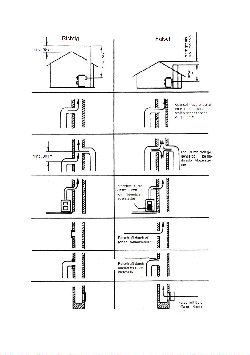
Correct
Incorrect
min.50cm
min.5m
below
5m
Lower as the
top of the roof
min.30cm
Tightening cross section
of the chimney because
the smoke tube is
pushed
too much
Obstruction ,
because
smoke tubes are
led as facing each
other
Faulty draught,
because a
fire
-place’s
door (not in
use) is open
False air because of
an open tube joint
False air,
because of a
leaky tube joint
False air, because
fire-place door
into the chimney
the
a open
35

3. Technical specification
Typen:
109 65
RH6F
109 85
RH8F
109 85 RH8F
AUTOMATIC
Nominal performance
kW 6 8
8
Flue gas connection
backside
Ø
mm
Heating capacity (m3)
TAB2 DIN standard
Min. blast pressure at
nominal performance
Fuel
wood / BB 7“ (brown coal)
Flue gas stream
g/s
5,4 / 6,2
6,6 / 7,2
7,3 / 5,8
Flue gas temperature
C°
363 / 384
353 / 366
317 / 330
CO (13% O2) mg/Nm3
mg/Nm³
1208 / 386
1140 / 797
1110 / 758
CO (13% O2) %
%
0,096 / 0,03
0,09 / 0,06
0,09 / 0,06
CO
mg/MJ
776 / 226
732 / 469
713 / 447
Dust (13% O2) mg/Nm3
mg/Nm³
35 / 39
31 / 29
35 / 38
Dust
mg/MJ
28 / 23
20 / 17
23 / 24
OGC
mg/MJ
14 / 7
39 / 17
17 / 33
Efficiency %
%
80,2 / 78,3
80,7 / 78,4
80,5 / 80,7
Weight
kg
85
109,5
148
3.1 data, dimensiona l draw ings, pictures
-under favourable
-less favourable
-not favourable heating
circumstances
according to 18893 /
m³ 115/68/45 182/105/71
Pa 12
120
36

4 1 5/7 8 13
14
11
10
12
3 9 2
12
6
Description to the pictures
1. Iron coast plate
2. Furnace chamber door with glass
3. Ash door
4. Flue gas connection
5. Fuel selector („2” = wood, „1” = coal) (pic. 9)
6. Primary air regulator (pic. 10)
7. Secondary air selector
8. Casing painted
9. Furnace chamber walling
10. Riddle bar (inside) (pic. 13)
11. Ash bin
12. Door knob
13. Fire door (only 8kW version)
14. Socle
37

pic. 1: RH6F 6KW
RH6F 6kW
RH8F 8kW
RH8F Automatic NS
pic. 2: RH8F 8KW
pic. 3: RH8F Automatic NS 8kW
38

pic. 9
pic. 10
pic. 11
39

pic. 12
pic. 13
pic. 14
pic. 15
The specified dimensions and weights are approximate values, and thus have
only informative purposes.
We reserve the right to modify the designs as required in terms of technolog y or
quality!
We reserve the right to make changes which relat e to technical advances and / or to an improvement in quality. We accept no liability for printing errors and changes which occur after printing.
Haus – und Küchentechnik GmbH
Adalperostr. 86
D – 85737 Ismaning
Telefon +49 (0)89 32084-0
Telefax +49 (0)89 32084-294
www.wamsler.eu
40

FR
Préambule
Cher Client,
Nous vous félicitons d’avoir acheté un poêle Wamsler.
Vous avez fait le bon choix car ce produit est pour vous une garantie
de grande qualité, grâce à l’emploi de matériaux excellents et éprouvés
de sécurité de f onc tionnement, grâce à un e tec h ni q ue p ar f aitement au point
et sévèrement contrôlée selon la norme européenne EN 13240.
de longévité, grâce à la robustesse de construction.
Pour utiliser longtemps votre appareil, lisez attentivement cette notice. Vous
trouverez des informations concer nant l’installation, l’utilis ation, l’entretien ainsi
que des indications vous permettant d’économiser l’énergie.
Cette notice cite certa ines réglementations, mais n'est en aucu n cas exhaustive. Pour une installatio n correcte, il convient d onc de se reporter aux nor mes
et réglementations locales et nati onales ainsi qu'aux normes eur opéennes. En
particulier il est impératif de respecter les norm es suivantes avec leurs add itifs
et leur éventuelles mise à jour.
- la norme française DTU 24.1 P1 / 51-201 relative aux travaux de fumisterie.
- la norme européenne EN 13384-1 relative à une méthode de calcul des
conduits de fumée.
- la norm e européenne EN 12391-1 relative à la m ise en oeuvre de conduits
double parois en métal.
(Cette norme doit être proc hainement rem placée par la norm e européenne EN
15287-1 relative a la mise en oeuvre des conduits à pression négative)
Les normes DTU peuvent être commandées par internet à l'adresse :
http://boutique.cstb.fr
Les normes EN peuvent être commandées par internet à l'adresse :
http://www.boutique.afnor.org
Pour garantir une combustion propre et préserver notre environnement les
chambres de combus tion des poêles doivent être les plus chau des possibles.
Pour cela elles sont isolées avec des plaques de verm iculite. La v erm iculite est
un excellent isolant qui rés iste au contact de la flamm e mais qui est sensible
aux chocs.
Ces plaques sont des produits dits « consommables » et vous pourrez être
amené à les remplacer.
La garantie de ces pièces est assurée pendant 6 m ois contre tout défaut de
fabrication.
41

30
FR
Pour les préserver il faut veiller à respecter les quantités maximum de bois
(indiquées dans cette notice) et éviter les chocs lors de l'introduction des
bûches.
Ainsi vous pourrez profiter de votre poêle plusieurs saisons sans les remplacer.
La pierre ollaire est un produit naturel avec des nuances de couleur et des
veines, en aucun cas l'aspect de la pierre est un motif de réclamation.
Attention
Pour toute commande de pièces de rechange indiquer le № de type, le №
de référence et le № de série inscrite sur la plaque signalétique de
l’appareil.
Sommaire
Préambule ................................................................................................................... 40
Sommaire .................................................................................................................... 42
1. Utilisation ................................................................................................................. 43
1.1 CONSIGNES DE SECURITE ................................................................................ 43
1.2 Mise en service ...................................................................................................... 45
1.3 Extinction ............................................................................................................... 47
1.4 Le poêle ne peut fonctionner qu’avec la porte fermée .......................................... 47
1.5 Nettoyage et entretien ........................................................................................... 47
1.6 Anomalies .............................................................................................................. 49
2. Installation ............................................................................................................... 50
2.1 Prescriptions d’ installation .................................................................................... 50
2.2 Air de combustion .................................................................................................. 50
2.3 Distances minimum ............................................................................................... 50
2.4 Raccordement au conduit de cheminée ................................................................ 51
3. Données technipues ................................................................................................ 52
3.1 Données, Plans avec les dimensions .................................................................... 52
42

1. Utilisation
1.1 CONSIGNES DE SECURITE
1. Les appareils ont été contrôlés selon les norm es EN 13240 (Plaque signalétique).
2. Pour la mise en place des appareils et le raccordement aux cheminées d’évacuation des
gaz, on devra observer les exigences énoncées par les directives concernant les appareils de chauffage (FeuFO en Allemagne) ainsi que les normes DIN 18896,
DIN 4705, EN 13384, DIN 18160, EN 1856-2 et EN 15287. Pour que votre appareil
puisse fonctionner correctement, il est nécessaire que l’état de la cheminée à laquelle
vous voulez raccorder l’appare il soit aus si impeccable.
3. Avant la première mise en service et avant de brancher l’appareil à la cheminée, vous
devez lire les instructions de service avec soin et informer le ramoneur responsable de
votre quartier.
4. Lors de l’installation des appareils, nous vous recommandons de porter des gants de
coton propres pour éviter que les empreintes qui sont ensuite difficiles à supprimer.
5. Afin d’éviter toute pollution de l’air et d’assurer le bon fonctionnement de votre appareil,
vous ne devez pas dépass er la charge maximale de combustible indiquée dans les instructions de service et les portes de l’appareil doivent être fermées. Dans le cas contraire,
l’appareil risque de surchauffer ce qui peut l’endommager. Les dommages de ce genre ne
sont pas couverts par la garantie.
6. Les portes de l’appareil doivent toujours rester fermées pendant le fonctionnement.
7. Les combustibles autorisés sont :
- le bois de chauffage naturel (la longueur des bûches ne devra pas dépasser 33 cm)
- les briquettes de lignite (cf. combustibles dans les instructions de service)
8. N’utilisez jamais de liquides pour faciliter l’allumage. Pour allumer le feu, on devrait utiliser
des allume-feu spéciaux ou de la fibre de bois.
9. Il est strictement interdit d’utiliser comme combustibles, des déchets, des détritus, des
écorces, du bois humide ou traité avec un produit de conservation, du papier, du carton,
etc.
10. Lors de la première mise à feu, il est possible que des fumées et des odeurs désagréables se dégagent. Il est impératif de veiller à ce que la pièce soit bien aérée (portes
et fenêtres ouvertes) et de chauffer au moins une heure à la puissance calorifique nominale maximale. Si durant la première proc édure de chauffage, la température maximale
n'est pas atteinte, il est possible que de tels dégagements se reproduisent à l’avenir.
11. Les éléments de commande et les dispositifs de réglage devront être ajustés conformément aux instructions de service. Lorsque l’appareil est chaud, nous vous prions d’utiliser
les outils appropriés ou des gants de protection.
12. En ouvrant la porte de chargement il peut arriver que de la fumée se dégage dans le cas
d’une fausse manœuvre ou si le tirage de la cheminée est insuffisant. Il faut impérativement veiller à ce que la porte de chargement soit toujours ouverte lentement ; tout
d’abord, elle devra être légèrement entrouverte. Elle ne sera complètement ouverte qu’au
bout de quelques secondes. Par ailleurs, avant d’ouvrir la porte de chargement pour remettre du combustible, on s’assurera qu’il n’y a que des braises dans la chambre de
combustion, c'est à dire qu'on ne peut plus voir de flammes.
13. Aucun objet combustible ne pourra être placé dans le compartiment de conservation des
plats au chaud et sur l’appareil.
14. Pendant le chauffage toutes les surfaces, et en particulier, les vitres du chauffage, les
poignées et les dispositifs de commande peuvent devenir très chauds. Attirez l’attention
43

des enfants et des jeunes adolescents, ainsi des personnes âgées et des handicapés sur
ces risques et faites en sorte qu’ils se tiennent éloignés de la source de feu pendant le
chauffage. Pour la commande ou le chargement de la cuisinière, utilisez le gant de protection ou les outils qui font partie du détail de la fourniture. Les enfants et les jeunes de
moins de16 ans ne peuvent commander ou charger la cuisinière sans qu’un adulte chargé de l’éducation ne soit présent.
15. On doit toujours veiller à ce que le bac à cendre soit poussé jusqu’à la butée. Il ne faut
pas jamais jeter la cendre chaude (danger d’incendie).
16. Pendant les périodes d’intersaison, il peut arriver que le tirage soit perturbé de sorte que
les gaz et les fumées dégagés ne sont pas entièrement évacués. L’appareil de chauffage
ne doit être alors rempli que d’une quantité réduite de combustible, de préférence des copeaux ou de la fibre de bois et sera d’abord allumé sous contrôle pour stabiliser le tirage.
La grille doit rester propre.
17. Après chaque période de chauffage, il convient de faire contrôler les appareils par un
technicien spécialisé. De même, les conduits de fumées et les tuyaux de cheminée devront être nettoyés à fond.
18. S’il est nécessaire de procéder à des réparations ou à des remplacements adressez-vous
à temps à votre commerçant spécialisé en lui indiquant exactement le numéro de référence et le numéro de fabrication. On ne peut utiliser que des pièces originales W AMSLER.
19. Les travaux, tels que, en particulier, l’installation, le montage, la première mise en service,
les travaux de maintenance ainsi que les réparations ne pourront être effectués que par
une entreprise spécialis ée (chauffagiste et fumis tes) disposant d’un personnel qualifié en
la matière. Dans le cas d’interventions incorrectes toutes les garanties - y com pris aus si
la garantie contre tout défaut de matière et vice fabrication - seront annulées.
20. Comme le poêle ou la cuisinière à combustibles solides prend l’air dont il a besoin de la
pièce où il est installé, on veillera à ce que suffisam ment d’air puisse être amené par les
portes ouvrant sur l’extérieur ou par les fenêtres. On peut partir du principe que cette alimentation en air est garantie par un volume de 4 m³ par kW de puissance calorifique nominale. Si le volume est inférieur, il est possible d’assurer une alimentation en air de
combustion correcte en reliant plusieurs pièces grâce à des ouvertures d’aération (au
moins 150 cm²).
21. On veillera à maintenir les distances de l’appareil à l’avant, à l’arrière et sur les côtés par
rapport à des éléments de construction combustibles. Vous trouverez ces distances dans
les instructions de service ou sur la plaque signalé tiq ue.
22. Le foyer ne doit pas être modifié sur le plan technique.
23. Le raccordement à une cheminée dont la hauteur efficace est inférieure à 4 mètres, et
dans le cas de plusieurs appareils, à 5 mètres, n’est pas autorisé. Sur la cheminée à laquelle est branchée le poêle, seulement deux foyers supplémentaires – au plus- peuvent
être encore raccordés.
24. Dans le cas d’un feu de cheminée, fermez toutes les ouvertures de l’appareil et avertissez
immédiatement les pompiers. N’essayez, en aucun cas, d’éteindre l’incendie vous-même.
Ensuite, vous devrez faire contrôler la che minée p ar un spécialiste.
25. Par leur nature, les combustibles solides produisent de la suie, il n’est jamais exclu que
les vitres de la porte de chargement se salissent. C’est pourquoi un tel dépôt de suie ne
saurait constituer un sujet de réclamation.
44

1.2 Mise en service
Combustible
Ce poêle à bois convient aux combustibles suivants :
Bois bûches de longueur au maximum 33cm
TOUT COMBUSTIBLE AUTRE QUE LE BOIS EN BUCHEs EST INTERDIT.
Les feuillus durs (chêne, hêtre, frêne, châtaignier, charme, noyer, fruitiers, etc.) fournissent un bois de chauffage de meilleure qualité, qui dégage plus de chaleur en brûlant
plus longtemps que les résineux.
L’HUMIDITE DU BOIS DOIT ETRE INFERIEURE A 20%
Le critère de l'humidité intervient directement sur le contenu énergétique.
Entre un bois sec prêt à l'emploi (moins de 20 % d'humidité rapportée à la masse brute)
et un bois fraîchement coupé (45 % d'humidité rapportée à la masse brute), l'énergie es t
deux fois moindre !
Il faut également savoir qu’utiliser un bois humide entraîne une augmentation des émissions polluantes.
Le bois de chauffage fraîchement abattu, conditionné en 1 m, doit être stocké au minimum 3 ans. Coupé à 50 cm, fendu et conservé sous abri dans un endroit bien ventilé, le
bois sèche plus vite et le délai minimum est ramené à 2 ans.
Toute combustion de bois "souillé" c'est-à-dire traité ou enduit de vernis, de bois de
démolition ou de vieux meubles est interdite. Ce type de bois risque de détériorer votre
appareil. et engendre des émissions polluantes et toxiques !
En résumé : un bon bois de chauffage est un bois "propre" et sec.
Quantité de remplissage:
Veillez à ne jamais surcharger la chambre de combustion.
RH6F 6 kW
-Bois fendu: 33 cm de longueur au maximum 1-2 morceaux de 1,4 kg chacun
-Lignite au maximum 1-2 morceaux de 1,5 kg chacun
RH8F 8 kW
-Bois fendu: 33 cm de longueur au maximum 1-2 morceaux de 1,9 kg chacun
-Lignite au maximum 1-2 morceaux de 2,2 kg chacun
RH8F Automatic 8 kW
-Bois fendu: 33 cm de longueur au maximum 1-2 morceaux de 1,9 kg chacun
NWL endurance brûler les briquettes de lignite max. Mettez 8,2 kg (15 pcs.) Sur la
braise, max. 8,2 kg / 4h Pour obtenir une combustion propre, il vaut mieux fractionner
les charges
Réglez ensuite la prise d’air primaire.
Cuisant:
EN 12815. Le contrôle d'air primaire doit être réglé selon
le tableau 1 pour la cuisson "cooking" et avec le maximum
spécifié ci-dessous quantités de carburant pour fonctionner.
Le pot doit être mis à l'emplacement prédéterminé de la
plaque chaude (fig.). Eviter les surcuisson et projections de
graisse.
Cheminée
Cheminée
Cheminée
Le dispositif répond au critère de cuisinière
45

Réglage d’air:
Sélecteur
secondaire
Réglage air
Automatic
foyère en
bas
panneau
arrière
foyère en
bas
Fig. „C“
(max)
Puissance
nominale
Puissance
nominale
Fig. „A“
(min)
Fig. A (Min.)
Fig. B
Fig. C (Max.)
Allumage
Bois
Utilisation
Réglage air
primaire
III H
I H Fig „B“
II K Fig. „C“
combustible
air
Lignite
Dauerbrand - K
Mise hors service
Bois
Lignite
Cuisant
Tableau 1.
0 K Fig. “A”
III H III K -
Appareils de réglage automatique RH8F Automatic
Réglez bouton de commande de porte de cendres que le tableau 1.
primaire
RH8F
Bouton de réglage entre 0 et définir max à la performance souhaitée.
Avant le premier allumage :
Avant le premier allumage retirez les éléments de protection pour le transport.
Le premier allumage :
ATTENTION : Il est normal que lors des premières utilisations de votre appareil, il y ait un
dégagement d'odeurs et de fumées dues à la cuisson de la peinture.
CONSEIL : Choisir une belle journée pour réaliser les premiers allumages, cela vous permettra d’ouvrir les fenêtres. Commencez par un petit feu d’une heure puis augmentez
progressivement l'allure.
46

L'allumage
● vérifier que votre prise d'air extérieure est ouverte.
● ouvrir la porte en basculant la poignée vers le haut (voir fig. 11+12).
● ouvrir la prise d’air primaire (voir fig. 9+10).
● disposez un peu de papier ou d’allume feu conseillé pour le bois (sans soufre),
sur la grille puis un peu de petit bois et ensuite du bois plus gros.
● Allumez et fermez la porte.
N’utilisez en aucun cas de produit inflammable liquide.
1.3 Extinction
Laissez toujours brûler complètement le poêle jusqu’à ce qu’il s’éteigne de lui même.
Ne jamais utiliser de l'eau pour éteindre votre poêle.
Lors de la mise hors service en fin de saison de chauffage, videz le foyer et le tiroir à
cendres, fermez la porte et le réglage d’air primaire. La prise d'air extérieur peut également
être fermée.
1.4 Le poêle ne peut fonctionner qu’avec la porte fermée
La porte ne doit être ouverte que pour l'allumage, l'alimentation en combustible ou le nettoyage.
1.5 Nettoyage et entretien
Une diminution des performances de chauffage est presque toujours la conséquence d 'un
mauvais entretient du poêle et du conduit d'évacuation des fumées.
Vous devez faire ramoner votre conduit de cheminée au moins 2 fois par an ou plus en cas
d'utilisation intensive de votre poêle.
Pour le nettoyage de l’intérieur du poêle, il est conseillé de retirer le pare flamme. Après le
nettoyage le pare flamme doit être remis en place.
Avant de commencer le nettoyage assurez-vous que le poêle soit bien froid. L’intervalle
entre les nettoyages dépend du temps d'utilisation et de la qualité des combustibles utilisés.
Aspiration des cendres
Dans l’âtre le bois brûle et laisse des cendres. Attention : il peut rester des tisons
chauds dans les cendres. Mettez-les dans un bidon en tôle.
La cendre peut être aussi poussée dans le cendrier qui se trouve sous la grille de combustion.
La cendre est un produit naturel. Mélangée à la terre c'est un engrais de grande qualité
approprié au jardin, à la pelouse et aux fleurs en pot.
Nettoyage de la vitre
Le combustible bois produit naturellement de la suie, ce qui entraîne la salissure de la
vitre. Vous devez utiliser des produits spéciaux pour vitre d'appareil de chauffage au
bois.
Ces produits lave vitres ne doivent être utilisés que pour le nettoyage de la partie
intérieure de la vitre.
Toutes les autres surfaces vitrées se nettoient facilement avec un chiffon humide ou un
lave vitres et se rincent avec un chiffon doux. Lors de ces nettoyages veillez à ne pas
47

projeter de produit sur les parties peintes. (rincez immédiatement à l’eau claire et
essuyez avec un chiffon doux.)
La vitre reste propre plus longtemps si vous suivez ces quelques recommandations:
● Utilisez de petites bûches et en petites quantités
● Pas de combustible humide ! Lors de la combustion de la vapeur d’eau
s’échappe du bois, se dépose, et condense sur la vitre froide. Utilisez des
allumes feux adaptés, pas de papier glacé ni de carton.
● Faites le feu le plus loin possible de la vitre afin d'éviter un contact direct avec
celle-ci.
Nettoyage des parties peintes
Les surfaces peintes doivent être nettoyées avec un chiffon doux et légèrement humide, n’utilisez pas de produit détergent.
Attention
N’utilisez jamais de détergent agressif, d’éponges abrasives ou tout autre produit
d’entretien récurant.
48

1.6 Anomalies
Probleme
Cause
Solution
Dégagement
Durciss ement de la pei ntur e et
évaporation des résidus d’
Chauffez le poêle comme décrit
quelques heures.
Dégagement de
Capacité de chauffage insuffi-
Faites contrôler le dégagement de
née. Contrôlez surtout les clapets
Traitez d’éventuelles fuites à
l’aide d’un produit d’étanchéité .
Fuite de la porte vitrée.
Vérifiez l’étanchéité. Si nécessaire,
remplacer les joint de vitre et de
porte.
Combustion de bois trop humide.
N’utilisez que du bois bien sec.
Les vitres se
salissent
Combustion de bois trop humide.
N’utilisez que du bois bien sec.
Utilisation d'une puissance de
Faire chauffer plus fortement le
avec plusieurs bûches, ensuite
à une puissance plus faible.
Tirage de la cheminée trop
faible.
Vérifiez s’il faut ramoner la cheminée.
Aération insuffisante dans la
pièce causant une dépression.
Ouvrez une entrée d'air extérieure
d’odeur
chaleur insuffisant.
huile.
sante. Tirage de la cheminée
insuffisant.
combustion insuffisante.
pendant quelques heures sur la
position minimum. Ensuite le faire
chauffer au maximum pendant
chaleur par votre revendeur. Le
tirage dans la cheminée doit être au
minimum de 12 pascal, max. 18 Pa.
Vérifiez l’ étanchéité de la chemi-
de nettoyage qui ne sont pas fermés.
poêle
réglez
49

2. Installat ion
2.1 Prescriptions d’installation
Le bon fonctionnement de votre poêle est fortement lié à la qualité de son installation.
L'installation doit être effectuée par un professionnel ou une personne qualifiée.
Cette notice comprend des recommandations propres à votre poêle. Il est impératif de
suivre ces recommandations pour bénéficier des meilleures performances mais aussi d e la
garantie sur cet appareil. Le non respect de c es recommandations annule la garantie.
2.2 Air de combustion
Lors de la combustion le poêle aspire de l'air dans la pièce où il est installé. Cet air
aspiré doit être compensé par une amenée d'air extérieur à l'habitation.
Si cette règle n'est pas respectée :
- la pièce dans laquelle est situé le poêle risque de se trouver en dépression.
Cela aura pour conséquence un mauvais fonctionnement.
- Dans certains cas extrêmes et notam ment si l'habitation est équipée avec un système
de Ventilation Mécanique Contrôlée (V.M.C.) ou de hotte aspirante des dégagements
de monoxyde de carbone peuvent se produire dans la pièce. Le monoxyde de carbone
est un gaz incolore et inodore très toxique.
L'installation d'une amenée d'air extérieur est donc obligatoire. Cette arrivée d'air doit être
réalisée au plus prés du poêle, et doit communiquer directement avec l’extérieur ou avec
une autre pièce largement ventilée (ex: la cave ou le vide sanitaire). Sa section libre doit
être au minimum de 50 cm2.
2.3 Distances minimum
Tous les matériaux de construction combustibles, meubles , ou tissus de décoration doivent être protégés contre la chaleur à proximité du poêle. Pour cela vous devez prendre
en compte les distances de sécurité décrits ci-dessous :
Distance de sécurité dans la zone de rayonnement
Dans la zone visible du feu (zone de rayonnement) une distance minimum de 1 m doit
être respectée entre les matériaux combustibles, (meubles, tiss us de décoration, etc) et
la façade du poêle. La distance de sécurité est réduite à 50 cm si une protection aérée
contre le rayonnement est montée devant les parties à protéger.
50

Distance de sécurité hors de la zone de rayonnement
Typ 109 65 RH6F 6kW
25 cm
45 cm
100 cm
Typ 109 85 RH8F 8kW
30 cm
50 cm
100 cm
Typ 10985 RH8F Automatic 8kW
30 cm
30 cm
80 cm
Une distance minimum de « Table 1 » doit être r espectée entre les matériaux combus-
tibles, et la paroi arrière du poêle.
Une distance minimum de « Table 1 » doit être respectée entre les matériaux combus-
tibles, et les parois latérales du poêle.
Sol dessous et devant le poêle
Les sols en matériaux combustibles tels que tapis, parquet ou liège doivent être remplacés ou protégés en les couvrant d’une matière incombustible sous le poêle ainsi que devant l’ouverture du foyer sur 50 cm minimum à l’avant et 30 cm sur le coté. Nous vous
conseillons de placer sous le poêle une plaque de protection en verre ou acier
Type
paroi ar-
rière
parois
latérales
zone de
rayonnement
Table 1
2.4 Raccordement au conduit de cheminée
Le conduit:
Le poêle doit être raccordé à un conduit qui convient pour des combustibles solides
conformément à la norme française DTU 24.1 P1 / 51-201 relative aux travaux de fumisterie.
Pour un bon fonctionnement il est impératif que votre conduit de fumée soit compatible
avec votre poêle.
Votre conduit doit notamment assurer un tirage suffisant et son isolation doit permettre
un fonctionnement sans condensation.
La norme EN 13384-1 décrit une méthode de calcul pour conduits de fumée. Cette
norme permet notamment de vérifier la compatibilité du conduit avec l'appareil qui sera
raccordé.
Cette vérification doit im pérativement être réalisée par un professionel. Pour effectuer
ces vérifications, il faut utiliser les caractéristiques présentées dans le « Tableau des
caractéristiques techniques » du poêle.
Raccordement au conduit de cheminée :
Ces travaux doivent être réalisés par un professionnel. Attention : les tuyaux de poêles
et toutes les pièces de raccordement doivent être adapté aux combustibles solides.
51

Si les éléments de conduit de raccordement mènent vers des éléments inflammables , il
109 85
Automatic
Buse d’évacuation des fumée
arrière
DIN18893/TAB2 dans les conditions
Bois / lignite
Débit massique des fumées
g/s
5,4/6,2
6,6/7,2
7,3 / 5,8
Température moyenne de fumées
C°
363/384
353/366
317 / 330
poussière (à 13% O2)
mg/Nm3
35 / 39
31 / 29
35 / 38
poussiére
mg/MJ
28 / 23
20 / 17
23 / 24
CO (à 13% O2)
mg/Nm3
1208/386
1140/797
1110 / 758
CO (á 13% O2)
%
0,096 / 0,03
0,09 / 0,06
0,09 / 0,06
CO
mg/MJ
776 / 226
732 / 469
713 / 447
OHC
mg/MJ
14 / 7
39 / 17
17 / 33
Rendement
%
80,2 / 78,3
80,7 / 78,4
80,5 / 80,7
Poids
kg
85
109,5
148
doivent impérativement être à une distance minimum de 3 fois le diamètre du conduit.
Cette distance peut être réduite de moitié si une protection contre le rayonnement (ininflammable) créant un vide d'air est installée entre le conduit et les matériaux inflammables.
En cas d'impossibilité de respecter cette règle les matériaux inflammables doivent être
déposés pour être remplacés par des éléments non inflammables.
3. Données technipues
3.1 Données, Plans avec les dimensions
Type
Puissance nominale kW 6 8
Ø mm 120
109 65
RH6F
109 85
RH8F
RH8F
Volume chauffée m3 après
-optima
-médiocres
-mauvaises
Tirage minimum Pa 12
m³
115
68
45
182
105
71
52

4
1
5/7 8 13
14
11
10
12
3
9
2
12
6
Légende des images
1. Acier fondu plaque
2. Porte foyère par fenêtre
3. Cendre porte
4. Buse d’évacuation des fumée
5. Sélecteur de combustible („2” = Bois, „1” = Lignite) (Fig. 9)
6. Réglage d’air primaire (Fig. 10)
7. Réglage d'air secondaire
8. Tôle d'habillage émaill er
9. Garniture intérieure
10. Tige de maneuvre du décendrage (deda ns) (F ig. 13)
11. Cendrier
12. Poignée d’ouverture
13. Porte de braises
14. Fondement
53

Fig. 1.: RH6F 6kW
RH6F 6kW
RH8F 8kW
RH8F Automatic NS
Fig. 2:: RH8F 8kw
Fig. 3.: RH8F Automatic NS 8kW
54

Fig. 9
Fig. 10
Fig. 11
Fig. 12
Fig. 13
Fig. 14
55

Fig. 15
La taille apparaitre et les donnée informer de caractères!
Notre frimée la structure modification entretenir doit, en tant qu’ils lèvent technique
niveau ou ils améliorent la qualité!
Nous réservons le droit d’apporter des modifications qui contribuent aux progrès techniques et / ou apportent une amélioration de la qualité. Nous déclinons toute responsabilité
pour des fautes d’impression ou pour des changements intervenus après la date
d’impression.
Haus – und Küchentechnik GmbH
Adalperostr. 86
D – 85737 Ismaning
Telefon +49 (0)89 32084-0
Telefax +49 (0)89 32084-294
www.wamsler.eu
56

Gentilissimo Cliente,
ATTENZIONE
N°
di serie/Serial No. riportati sulla targa di identificazione dell’apparecchio.
I
ci complimentiamo con Lei per aver acquistato questa stufa da riscaldamento e
per l’ottima scelta effettuata!
Questo prodotto Le garantisce
• qualità elevata grazie all’utili zzo di ottimi materiali testati
• funzionamento sicuro grazie alle avanzate tecnologie verificate in modo
rigoroso in base alla norma europea EN 13240
• lunga durata nel tempo grazie alla robusta struttura
Per garantire un lungo funzionamento nel tempo della Sua stufa è importante
leggere attentamente le seguenti istruzioni, nelle quali troverà tutte le informazioni necessarie oltre che utili suggerimenti.
Per la richiesta di pezzi di ricambio indicare il N° di articolo/Article No. e il
INDICE
Gentilissimo Cliente .....................................................................................................57
INDICE .........................................................................................................................57
1. Istruzioni per l’uso ....................................................................................................58
1.1 AVVERTENZE DI SICUREZZA .............................................................................58
1.2 Accensione ............................................................................................................60
1.3 Spegnimento ..........................................................................................................63
1.4 Generalità sul funzionamento ................................................................................63
1.5 Pulizia e manutenzione ..........................................................................................64
1.6 Cause e risoluzione anomalie ................................................................................65
2. Installazione .............................................................................................................66
2.1 Prescrizioni e norme ..............................................................................................66
2.2 Distanze di sicurezza .............................................................................................67
2.3 Collegamento alla canna fumaria ..........................................................................67
3. Schede tecniche ......................................................................................................72
3.1 Disegno dimensionale e dati ..................................................................................72
57

1. Istruzioni per l’uso
1.1 AVVERTENZE DI SICUREZZA
1. L’ apparecchio e i suoi dispositivi sono stati testati sulla base della norma
EN 13240 o secondo EN 12815 (vedi targa di identificazione).
2. Per un funzionamento ottimale della Sua stufa è fondamentale che la c anna fuma-
ria alla quale volete effettuare il collegamento sia in condizioni perfette.
• L’installazione e l’uso delle apparecchiature, deve avvenire esclusivamente in am-
biente giudicato idoneo dagli enti preposti e soprattutto in conformità alle norme e
prescrizioni vigenti in materia.
• Gli impianti tecnologici e l’installazione degli apparecchi devono essere effettuati da
personale professionalmente qualificato, autorizzato a rilasciare certificato di conformità e rispondenza alle norme in vigore.
• Nel luogo di installazione devono essere rispettate tutte le l eggi, norme e direttive
in vigore, in materia di edilizia civile e/o industriale, utilizzando sempre i dispositivi
di sicurezza individuale e gli altri mezzi di protezione previsti per legge.
• Devono inoltre essere rispettate tutte le leggi, norme, dir ettive in vigore in materia
di impiantistica, canne fumarie, elettricità, acqua, ventilazione/aspirazione.
3. Prima di procedere all’accensione dell’apparecchio, leggere attentamente tutte le
istruzioni per l’uso e contattare un tecnico specializzato.
4. Per il posizionamento degli apparecchi si consiglia di indossare guanti puliti di
cotone per evitare di lasciare impronte digitali difficili da rimuovere in seguito.
5. Per mantenere l’aria pulita e garantire un funzionamento sicuro dell’apparecchio, il
carico del combustibile non deve superare le quantità massime indicate nelle istruzioni per l’uso. Gli sportelli devono inoltre rimanere sempre chiusi per evitare un
surriscaldamento che danneggerebbe la stufa. Eventuali danni come quello appena descritto non sono coperti dalla garanzia.
6. Quando l’apparecchio è in funzione gli sportelli devono sempre rimanere chiusi.
7. Sono ammessi i seguenti combustibili:
- ceppi di legna allo stato naturale (lunghezza max. 33 cm)
- mattonelle di lignite (v. tabella dei combustibili ammessi nelle istruzioni per l’uso)
8. Non utilizzare combustibili liquidi per l’accensione. Utilizzare solo appositi accendi
fuoco o bricchetti di legno.
9. È vietato bruciare rifiuti, minuzzoli di legna, corteccia, polverino di carbone, trucioli,
legna umida e trattata con antisettici, carta, cartone e simili.
10. Durante la prima accensione la stufa potrebbe emanare fumi e odori sgradevoli.
Provvedere subito ad arieggiare bene il locale (aprire porte e finestre) e riscaldare
alla potenza termica nominale massima per almeno un'ora. Se non viene raggiunta
la temperatura massima con il primo riscaldamento, questi fenomeni potrebbero ripresentarsi anche in seguito.
11. Gli elementi di comando e i dispositivi di impostazione sono da regolare secondo le
istruzioni per l’uso. Se l’apparecchio è caldo si raccomanda di servirsi di attrezzi
speciali o dei guanti di protezione.
12. Aprendo lo sportello del focolare potrebbe verificarsi un’uscita di fumo dovuta ad un
utilizzo improprio o ad uno scarso tiraggio della canna fumaria. Si raccomanda per-
58

tanto, di aprire lo sportello lentamente e solo di qualche centimetro, prima di aprirlo
completamente. Prima di aprire lo sportello per la ricarica di combustibil e, assicurarsi che nel focolare vi sia solo il letto di brace e che le fiamme siano tutte spente.
13. Quando la stufa è in funzione tutte le superfici, in particolare i vetri, le maniglie e i
dispositivi di comando, possono raggiungere temperature elevate. È importante
controllare che bambini, adolescenti, persone anziane e animali domestici mantengano una distanza di sicurezza dall’apparecchio quando questo è in funzione. Per
manipolare la stufa servirsi del guanto di protezione o degli attrezzi speciali forniti.
Bambini e adolescenti al di sotto dei 16 anni possono utilizzare la stufa solo se sorvegliati da adulti.
14. Assicurarsi che il cassetto cenere venga sempre spinto nella sua sede fino al
raggiungimento dello scatto e, soprattutto, che non vengano smaltiti tizzoni/braci
ardenti (pericolo di incendio).
15. Nei periodi di mezza stagione possono verificarsi anomalie della canna fumaria che
possono compromettere la corretta espulsione dei gas combusti. In questo caso è
opportuno riempire la camera di combustione con una quantità minore di combustibile, meglio se con trucioli o bricchetti di legno. Quindi mettere in funzione la stufa e con attenzione, stabilizzarne il tiraggio. Per un buon funzionamento della stufa
la Griglia Focolare deve essere pulita quotidianamente.
16. Dopo ogni accensione stagionale è opportuno far ispezionare la stufa da tecnici
qualificati ed effettuare una pulizia completa di tubi e giro fumi.
17. Per eventuali riparazioni o sostituzioni contattare tempestivamente il proprio riven-
ditore avendo cura di comunicare l’esatto n° di articolo e di serie dell’apparecchio.
Tutti i componenti dovranno essere sostituiti esclusivamente con pezzi originali
Wamsler.
18. Eventuali lavori, in particolare l’installazione, il montaggio, la prima accensione,
nonché i servizi di assistenza e di riparazione possono essere esegui ti sol o da una
ditta specializzata (in impianti di riscaldamento o riscaldamento ad aria). Eventuali
installazioni errate faranno decadere ogni forma di garanzia.
19. È importante che vengano rispettate le distanze di sicurezza ai lati e sul retro per
tutti i componenti e materiali infiammabili. Le distanze sono riportate nelle istruzioni
per l’uso o sulla targa dell’apparecchio.
20. È vietato apportare qualsiasi tipo di modifica all’apparecchio.
Non è ammesso il collegamento ad una canna fumaria con altezza utile inferiore ai
4 metri. In caso di incendio della canna fumaria chiudere subito tutte le aperture
dell’apparecchio e avvertire i Vigili del Fuoco. Non provare in nessun caso a spegnerlo autonomamente. Dopo l’incendio è assolutamente necessario far ispezionare la canna fumaria da un tecnico specializzato.
21. Poiché i combustibili solidi bruciando producono fuliggine, sul vetro della stufa
potrebbero formarsi depositi; ciò non è da considerarsi un difetto dell’apparecchio.
22. Essendo la pietra ollare/arenaria pietre naturali, eventuali alterazioni cromatiche
sono normali e non costituiscono motivo di reclamo.
23. L’apparecchiatura deve essere impiegata solo per l’uso per il quale è stata esplici-
tamente concepita, altri impieghi sono impropri e pertanto pericolosi.
24. L’ apparecchiatura non deve essere utilizzata come inceneritore.
59

25.
Tipo di combustibile
Valore calorico ca. kWh/kg
Legna dura
Mattonelle di lignit
4,0 – 4,2
5,3 – 5,5
In caso di vetro del portello focolare rotto e/o incrinato, così come in caso di anomalie di funzionamento, l’apparecchio non può essere messo in funzione, se non
dopo aver rimosso l’anomalia.
26. Non ostruire le aperture o feritoie di aspirazione o di smaltimento del calore.
27. Tutti i regolamenti locali, inclusi quelli riferiti alle Norme Nazionali ed Europee
devono essere rispettate nell’istallazione dell’apparecchio.
28. Il funzionamento dell’ apparecchio è di tipologia intermittente , quindi richiede che il
combustibile venga caricato manualmente durante il funzionamento.
1.2 Accensione
Combustibili
Per garantire un corretto funzionamento della stufa e una formazione minima di
fumo devono essere utilizzati esclusivamente i combustibili elencati di seguito:
legna secca allo stato naturale con umidità massima del 20% e mattonelle di lignite.
La leva di regolazione dell’aria secondaria è montata sul lato posteriore. Per il
legno impostarla sulla posizione 2 “H”, per la lignite sulla posizione 1 “K”.
Legna morbida
Bricchetti secondo DIN 51731
È vietato bruciare i seguenti combustibili:
4,3 – 4,5
5,0 – 5,2
Rifiuti, minuzzoli di legna, corteccia, polverino di carbone, trucioli, legna umida e
trattata con antisettici, carta, cartone e simili. Per l’accensione utilizzare bricchetti
di legno o accendi fuoco da grill.
N.B. Per l’ accensione non utilizzare mai: alcool, benzina, o altri combustibili liquidi.
Attenzione!
Durante la prima accensione la stufa potrebbe emanare fumi e odori sgradevoli. Provvedere subito ad arieggiare bene il locale (aprire porte e finestre) e riscaldare alla potenza termica nominale massima per almeno
un’ora. Se non viene ragg iunta la temp eratura ma ssima con la pr ima accensione, questi fenomeni potrebbero ripresentarsi anche in seguito.
Mediante la leva dell’ aria primaria è possibile impostare in continuo i valori
compresi nel campo di regolazione per ottenere la potenza calorica desiderata.
60

mpostazione aria di combustione:
Posizione
da
Posizione
tomatic
Sportello
disotto
Parete po-
steriore
Sportello
disotto
Bild C
(max)
Potenza termica
nominale
Potenza termica
nominale
Bild A
(min)
Mattonelle di li-
gnite
Fig. A (Min.)
Fig. B
Fig. C (Max.)
Le leve devono sempre trovarsi al centro dei simboli.
Brennstoff
Può essere programmato per
Ceppi di legna
Mattonelle di lignite
Dauerbrand - K
Spegnimento
Ceppi di legna
K Cucinare
Posizione
leva aria
primaria,
III H
I H Bild B
II K Bild C
0 K Bild A
III H III K -
Tabella 1
scelta com-
bustibile,
aria secon-
leva aria
primaria
RH8F Au-
Dispositivo di controllo a controllo automatico:
RH8F Automatic
Impostazione Quando il pulsante di controllo della porta cenere Einzundung perché
Tabella 1.
Manopola di controllo tra 0 e max impostato prestazioni desiderate.
61

Cucinare:
Il dispositivo è conforme alla prova del fornello EN 12815.
Il controllo dell'aria primaria deve essere impostata in base
alla tabella 1 per la cottura di "cucinare" e con il massimo
di seguito specificato. Quantità di carburante per funzionare.
La pentola deve essere impostata sulla posizione predeterminta della piastra calda
(Fig.). Evitare schizzi e grasso cuocere.
Quantità di carico orario:
RH6F 6 kW stufa
Per il legno non superare una quantità di 1 - 2 ceppi (lunghezza max. 33 cm) per un
carico di circa 1,4 kg. Per le mattonelle di lignite carico max. 1,5 kg (circa 1 - 2 pezzi).
RH8F 8 kW stufa
Per il legno non superare una quantità di 2 - 3 ceppi (lunghezza max. 33 cm) per un
carico di circa 1,9 kg. Per le mattonelle di lignite carico max. 2,2 kg (circa 2 pezzi).
RH8F Automatic 8 kW
Per il legno non superare una quantità di 2 - 3 ceppi (lunghezza max. 33 cm) per un
carico di circa 1,9 kg.
NWL resistenza masterizzazione mattonelle di lignite max. Mettere 8,2 kg (15 pz.)
Sulla brace, max. 8,2 kg / 4h
Prima accensione
• Prima di procedere all’accensione rimuovere il materiale di imballaggio del
parafiamma sopra il focolare ed eventualmente anche il nastro adesivo del
vetro senza lasciare residui.
Aprire lo sportello del focolare sollevando la maniglia verso l’alto (fig. 11). Se
l’apparecchio è caldo, utilizzare un guanto di protezione isolato. Impostare l’aria primaria e la scelta di combustibile (fig. 10+15) secondo quanto indicato dalla tabella 1.
Posizionare sulla griglia focolare bricchetti di legno o accendi fuoco e aggiu ngervi
sopra dei trucioli di legno. Procedere con una piccola carica di legna per poi aumentarne la quantità, accendere, e poi richiudere lo sportello del focolare. Quando la
fiamma si è ben sviluppata, e si è formato un buon strato di brace, aggiungere
un’ulteriore carica di combustibile. In seguito impostare l’aria primaria/seconda secondo quanto indicato dalla tabella 1.
Per la prima accensione è opportuno procedere in modo “lieve” con piccole quantità
di combustibile, per consentire ai componenti di abituarsi al calore. Durante questa
fase la stufa potrebbe emanare fumi e odori sgradevoli. Provvedere subito ad arieggiare bene il locale (aprire porte e finestre) e riscaldare alla potenza termica nominale
massima per almeno un'ora. Se non viene raggiunta la temperatura massima con la
prima accensione, questi fenomeni potrebbero ripresentarsi anche in seguito.
Il combustibile non deve essere gettato, ma appoggiato nel focolare con delicatezza per evitare di danneggiare la parte in muratura dell’apparecchio.
62

Attenzione!
Aprendo lo sportello del focolare potrebbe verificarsi un’uscita di fumo dovuta
ad un utilizzo improprio o ad uno scarso tiraggio della canna fumaria. Si raccomanda pertanto di aprire lo sportello lentamente, e solo di qualche centimetro,
prima di aprirlo completamente. Prima di aprire lo sportello per la ricarica di
combustibile, assicurarsi che nel focolare vi sia solo il letto di brace e che le
fiamme siano tutte spente.
1.3 Spegnimento
Chiudere gli sportelli e portare la regolazione dell’aria primaria/seconda in posizione
chiusa. Lasciar consumare la brace rimasta e far raffreddare la stufa. Pulire e svuotare il focolare e il cassetto cenere solo quando la stufa si è raffreddata a temperatura
ambiente! Raccomandiamo di far attenzione alla possibile presenza di braci o tizzoni
caldi.
1.4 Generalità sul funzionamento
Gli sportelli del focolare devono rimanere sempre chiusi mentre la stufa è in funzione. È possibile aprirli per l’accensione, l’aggiunta di carico o per la pulizia del focolare.
Un adeguato apporto di aria secondaria consente di bruciare anche i componenti
combustibili dei gas di scarico. Non può essere escluso un eventuale deposito di
sporco sul vetro dovuto ai combustibili solidi e ciò non è da considerarsi come un
difetto dell’apparecchio. Grazie a questo sistema la combustione genera poco fumo e
fuliggine garantendo il rispetto dell’ambiente. Qualora la stufa venga utilizzata nei
periodi di mezza stagione è necessario prima controllare il tiraggio della canna f umaria, che potrebbe essere scarso se la temperatura esterna è elevata. A questo scopo
avvicinare un fiammifero acceso allo sportello del focolare leggermente aperto. Se la
fiamma non dovesse tirare sufficientemente in direzione dell’apertura, bruciare per
breve tempo dei trucioli o bricchetti di legno nella stufa o nell’apertura di ispezione
della canna fumaria. Per consentire un buon apporto di aria, prima di ogni combustione pulire e scuotere la griglia focolare (Fig. 14). Svuotare regolarmente il cassetto
cenere ad apparecchio freddo (Fig. 13). Se l’apparecc hio è ancora caldo, indossare il
guanto di protezione fornito. Accertarsi che durante questa procedura non vengano
smaltiti residui di combustione ardenti (braci o tizzoni caldi).
Assicurarsi che il cassetto cenere venga sempre spinto nella sua sede fino al raggiungimento dello scatto.
Attenzione!
Per garantire aria pulita e una buona resa dell’apparecchio, il carico del combustibile non deve superare le quantità max indicate nelle istruzioni per l’uso per
evitare un surriscaldamento che danneggerebbe la stufa. Eventuali danni come
quello appena descritto non sono coperti dalla garanzia. Una minore resa termica si ottiene soltanto riducendo le quantità di carico e non mediante diminuzione dell’aria primaria.
63

1.5 Pulizia e manutenzione
Un buon utilizzo dell’app arecchio associato ad u n’accurata pulizia e m anutenzione garantiscono la stabilità dei valori e una lunga durata nel tempo
dell’apparecchio. Ciò consente di risparmiare preziose risorse, rispettare
l’ambiente ed evitare ulteriori spese. Per procedere a lla pulizia tirare in avanti il
parafiamma. In questo modo è possibile pulire il giro fumi dall’interno o, rimuovendo il tubo di scarico, dall’alto.
Al termine dell’opera zion e di p ul i zia re inser ir e i l parafiamma nella pos i zione i ni zi ale.
Attenzione!
A fine stagione è opport uno sottoporre l a stufa a una pulizia completa. P er
tuali riparazioni o sostituzioni contattare tempestivamente il proprio rivenditore avendo
cura di comunicare l’esatto n° di articolo e di serie dell’apparecchio (v. targa di identificazione).
La pulizia delle superfici esterne è da effettuare a stufa f redda. Devono essere pulite
con acqua corrente o, in casi particolari, pretrattate con acqua saponata o detersivo
per piatti, e poi strofinate fino a completa asciugatura.
Prima del primo utilizzo pulire il vetro ROBAX S della stufa con un panno umido e
pulito e aggiungere poi delle gocce di detergente per vetroceramica su entrambi i lati
del vetro mediante carta da cucina.
La pregiata superficie di ROBAX S è rivestita con una pellicola invisibile che consente
di mantenere il vetro pulito e che agevola le operazioni di pulizia se queste sono svolte regolarmente.
I combustibili solidi brucia ndo producono fuli ggine e la formazione sul vetro di
eventuali depositi non può essere mai del tutto esclusa; ciò non è da considerarsi un difetto dell’apparecchio.
Pulizia delle ceramiche: sporco e grasso possono essere rimossi con acqua e sapo-
ne.
Pulizia di pietra ollare e arenaria: essendo pietra ollare e arenaria pietre naturali,
eventuali alterazioni cromatiche sono normali e non costituiscono motivo di reclamo!
Sporco e grasso possono essere rimossi con acqua e sapone, piccoli graffi con carta
abrasiva a umido (grana 240).
Importante: non utilizzare in nessun caso spugne, abrasivi e detergenti a ggressivi o che potrebbero graffiare le superfici!
Eventuali lavori, in particolare l’installazione, il montaggio, la prima accensione,
nonché i servizi di assistenza e di riparazione possono essere eseguiti solo da una
ditta specializzata (in impianti di riscaldamento o riscaldamento ad aria). Eventuali
installazioni errate faranno decadere ogni forma di garanzia.
even-
64

1.6 Cause e risoluzione anomalie
Tipo di anomalia
Cause possibili
Rimedi
Formazione di odori:
Asciugatura della vernice
Lasciare la st uf a i n funz ione p er
Scarsa emissione di
• È stata scelta una poten-
• Far verificare il Suo fabbisogno
re
Utilizzare solamente legna ben
calore:
utilizzata ed evaporazione
dei residui di olio.
za troppo bassa
• Tiraggio troppo basso
Tubo di scarico troppo
lungo e non sigillato
• Sportelli vetro, focolare o
cenere non ermetici
• Combustione di legna
troppo umida
diverse ore sulla posizione minima così com e i ndi ca to ne lle
istruzioni per l’us o. I n s egu it o
lasciare risc alda re pe r di ver se
ore a potenza massima.
termico da un tecnico esperto.
• La stufa richiede un tiraggio
min di 12 Pa e può arrivare ad
un max. di 18 Pa per breve
tempo. Controllare la tenuta
della canna fumaria. Verificare
soprattutto le aperture della
canna fumaria e di pulizia. Se
necessario collegare un tratto
verticale.
• Tutti i collegamenti dei tubi di
scarico devono avere una buona tenuta stagna ed essere isolati con materiale refrattario.
• Controllare la tenuta e chiude
bene gli sportelli. In cas o far
sostituire i nastri sigillanti.
•
asciutta.
Provvedimenti da attuare in caso di incendio di canna fumaria
Una pulizia non completa della canna fumaria, l’utilizzo di combustibile non
idoneo (per esempio legna troppo umida) o l’impostazione sbagliata dell’aria
della combustione potrebbero provocare un incendio della canna fumaria. In
questo caso chiudere la presa d’aria della stufa e chiamare immediatamente i
Vigili del Fuoco.
N.B. Non provare mai ad estinguere il fuoco con acqua.
65

2. Installazione
2.1 Prescrizioni e norme
• Leggere attentamente il contenuto del presente manuale, in quanto fornisce
importanti indicazioni ed istruzioni riguardanti l’installazione, l’uso, la manutenzione e soprattutto la sicurezza del prodotto.
• L’installazione e l’uso delle apparecchiature, deve avvenire esclusivamente in
ambiente giudicato idoneo dagli enti preposti e soprattutto in conformità alle
norme e prescrizioni vigenti in materia.
• Gli impianti tecnologici e l’install azione degli apparecchi devono essere effettuati
da personale professionalmente qualificato, autorizzato a rilasciare certificato di
conformità e rispondenza alle norme in vigore.
• Nel luogo di installazione devono essere rispettate tutte le leggi, norme e direttive
in vigore, in materia di edilizia civile e/o industriale, utilizzando sempre i dispositivi di sicurezza individuale e gli altri mezzi di protezione previsti per legge.
• Devono inoltre essere rispettate tutte le leggi, norme, direttive in vigore in materia
di impiantistica, canne fumarie, elettricità, acqua, ventilazione/aspirazione.
• Il costruttore declina ogni responsabilità derivante da installazione errata,
manomissione, utilizzo non corretto dell’apparecchio, uso impro prio, cattiva manutenzione, inosservanza delle normative vigenti e imperizia d’uso.
Operazioni preliminari
• Togliere delicatamente l’imballo.
• Il materiale che compone l’imballo va riciclato mettendolo negli appositi conteni-
tori o conferito al sito preposto nel comune di residenza.
• Prima dell’installazione assicurasi dell’integrità dell’apparecchio, in c aso di dub-
bio non utilizzarlo e rivolgersi al rivenditore.
Posizionamento apparecchio
• Il sito d’installazione dell’apparecchio deve prevedere:
− Una pavimentazione di adeguata capacità di carico, superiore al peso
dell’apparecchio. Se la costruzione esistente non soddisfa questo requisito,
misure appropriate dovranno essere prese (Es. piastra di distribuzione di carico).
− Una pavimentazione adatta all’irraggiamento calorico che garantisca
l’edificio contro i rischi di incendio.
− L’installazione dell’ apparecchio deve garantire facile accesso per la pulizia
dell’apparecchio stesso, dei condotti dei gas di scarico e della canna fumaria.
66

2.2 Distanze di sicurezza
Typ
Dietro
laterale
Innanzi
Typ 109 65 RH6F 6kW
25 cm
45 cm
100 cm
Typ 109 85 RH8F 8kW
30 cm
50 cm
100 cm
Typ 10985 RH8F Automatic 8kW
30 cm
30 cm
80 cm
X
Proteggere dall’effetto del calore tutti gli elementi costruttivi, mobili o tessuti di arredamento infiammabili situati nelle vicinanze della stufa.
Oggetti all’interno della zona di irraggiamento
Per gli elementi costruttivi, i mobili e i tessuti di arredamento infiammabili situati nella
zona di irraggiamento della stufa è necessario rispettare una distanza minima di
80 / 100 cm (Tabella 2), misurati dal bordo anteriore dell’apertura del focol are. La
distanza di sicurezza si riduce ai 40 / 50 cm qualora di fronte all’elemento sia installata una protezione areata.
Oggetti al di fuori della zona di irraggiamento
Le pareti laterali e quella posteriore all’apparecchio non possono essere realizzate o
rivestite con materiale infiammabile qualora la distanza laterale sia inferiore alla “Ta-
bella 2” e quella posteriore alla “Tabella 2”.
Anche per mobili in legno o in plastica deve essere rispettata una di stanza laterale di
”Tabella 2”.
Tabella 2
Pavimento sotto e davanti alla stufa
I pavimenti in materiale infiammabile come moquette, parquet o sughero devono
essere sostituiti o protetti sotto la stufa, davanti fino a 50 cm dal bordo del focolare e
lateralmente fino a 30 cm da un rivestimento in materiale non infiammabile, come
ceramica, pietra, vetro o da una base salva-pavimento in acciaio.
2.3 Collegamento alla canna fumaria
ATTENZIONE!
Prima di procedere al collegamento dell’apparecchio consultare un tecnico
specializzato di zona!
I tratti di collegamento della stufa devono essere ben saldati
e sigillati e non devono essere inseriti in profondità nella
sezione trasversale libera della canna fumaria. Il tratto di
collegamento tra stufa e canna fumaria deve avere un diametro equivalente a quella del bocchettone di uscita fumi
della stufa. Tratti orizzontali superiori ai 0,5 metri devono
avere una pendenza di 10 gradi rispetto alla canna fumaria.
Tubi non isolati termicamente o con andamento orizzontale
non devono avere una lunghezza superiore ad un metro.
67

La Misura X (distanza da elementi costruttivi/materiali infiammabili) da rispettare è
Generalmente la stufa può essere
fumaria mediante impiego di curve.
Se il tiraggio è scarso la stufa do-
fumi verticale.
quella indicata dal produttore dell’apparecchio.
ATTENZIONE!
Per il dimensionamento della canna fumaria consultare i dati relativi all’apparecchio
nella sezione 3.
collegata direttamente alla canna
vrebbe essere collegata alla canna
fumaria mediante un tubo di scarico
CAMINO O CANNA FUMARIA
• Il camino o canna fumaria deve rispondere ai seguenti requisiti:
− Essere a tenuta dei prodotti della combustione, impermeabile ed adeguata-
mente isolato e coibentato alla stregua delle condizioni di impiego (UNI
9615);
− Essere realizzato in materiali adatti a resistere alle normali sollecitazioni
meccaniche, al calore, all’azione dei prodotti della combustione e alle eventuali condense;
− Avere andamento prevalentemente verticale con deviazioni dell’asse non
superiori a 45°;
− Essere adeguatamente distanziato da materiali combustibili o infiammabili
mediante intercapedine d’aria od opportuno isolante;
− Avere sezione interna preferibilmente circolare; le sezioni quadrate o rettan-
golari devono avere angoli arrotondati con raggio non inferiore a 20 mm;
− Avere sezione interna costante, libera e indipendente;
− Avere le sezioni rettangolari con rapporto massimo tra i lati di 1,5;
− Dovranno essere rispettate le indicazioni del costruttore dell’apparecchio per
quanto concerne la sezione e le caratteristiche costruttive della canna fumaria/camino. Per sezioni particolari, variazioni di sezione o di percorso dovrà
essere effettuata una verifica del funzionamento del sistema di evacuazione
fumi con appropriato metodo di calcolo fluidodinamico (UNI 9615).
− E’ consigliato che il condotto fumario sia dotato di una camera per raccolta
materiali solidi ed eventuali condense, situata sotto l’imbocco del canale da
fumo, in modo da essere facilmente apribile ed ispezionabile da sportello a
tenuta d’aria.
68

− In caso di incendio della canna fumaria munirsi di adeguati sistemi per soffo-
care le fiamme (es. utilizzare un estintore a polvere o ad anidride carbonica)
e richiedere l'intervento dei Vigili del Fuoco.
COLLEGAMENTO DELL’APPARECCHIO ALLA CANNA FUMARIA ED EVACUAZIONE DEI PRODOTTI DELLA COMBUSTIONE (vedi anche normativa
UNI 10683)
• Il collegamento tra l’apparecchio di utilizzazione e la canna fumaria deve ricevere
lo scarico da un solo generatore di calore.
• E’ ammessa la realizzazione di apparecchio composto da caminetto e forno di
cottura con un unico punto di scarico verso il camino, per il quale il costruttore
dovrà fornire le caratteristiche costruttive del raccordo dei canali da fumo.
• E’ vietato convogliare nello stesso canale da fumo lo scarico proveniente da
cappe sovrastanti gli apparecchi di cottura.
• E’ vietato lo scarico diretto verso spazi chiusi anche se a cielo libero.
• Lo scarico diretto dei prodotti della combustione deve essere previsto a tetto ed il
condotto fumario deve avere le caratteristiche previste precedentemente.
COMIGNOLO
• Il comignolo deve rispondere ai seguenti requisiti:
− Avere sezione interna equivalente a quella del camino;
− Avere sezione utile di uscita non inferiore al doppio di quella interna del ca-
mino;
− Essere costruito in modo da impedire la penetrazione nel camino di pioggia,
neve, corpi estranei e in modo che anche in caso di venti di ogni direzione e
inclinazione sia comunque assicurato lo scarico dei prodotti della combustione;
− Essere posizionato in modo da garantire una adeguata dispersione e dilui-
zione dei prodotti della combustione e comunque al di fuori della zona di reflusso in cui è favorita la formazione di contropressioni. Tale zona ha dimensioni e conformazioni diverse in funzione dell’angolo di inclinazione della copertura, per cui risulta necessario adottare le altezze minime indicate negli
schemi seguenti:
69

Inclinazione del tetto
C (°)
15
1,85
1,00
0,50
30
1,50
1,30
0,80
45
1,30
2,00
1,50
60
1,20
2,50
2,10
A H
Altezza della zona di reflusso Z (m)
REALIZZAZIONE DELL’ALLACCIAMENTO ALLA CANNA FUMARIA
70

• Eseguire il collegamento dell’apparecchi o alla canna fumaria del camino esisten-
te, assicurandosi che il tubo di uscita fumi non occupi la sezione libera della canna fumaria.
• Utilizzare esclusivamente tubi adatti allo smaltimento dei fumi della combustione.
• Limitare i tratti orizzontali del condotto di raccordo alla canna fumaria (max 1
metro) e l’uso di curve.
PRESA ARIA COMBUSTIONE DALL’AMBIENTE DI INSTALLAZIONE
• L’apparecchio deve poter disporre dell’aria necessaria a garantirne il regolare
funzionamento mediante prese d’aria esterna.
• Le prese d’aria devono rispondere ai seguenti requisiti:
a) Avere sezione libera totale minima di 200 cm²;
b) Essere comunicante direttamente con l’ambiente di installazione;
c) Essere protette con griglia, rete metallica o idonea protezione purché non ri-
duca la sezione minima di cui al punto a) e posizionate in modo da evitare
che possano essere ostruite.
• L’afflusso dell’aria può essere ottenuto anche da un l ocale adiacente a quello di
installazione, purché tale flusso possa avvenire liberamente attraverso aperture
permanenti comunicanti con l’esterno. Il locale adiacente rispetto a quello di installazione non deve essere messo in depressione rispetto all’ambiente esterno
per effetto del tiraggio contrario, provocato dalla presenza in tale locale di altro
apparecchio di utilizzazione o di dispositivo di aspirazione.
• Nel locale adiacente le aperture permanenti devono rispondere ai requisiti di cui
alle lettere a) e c).
• Il locale adiacente non può essere adibito ad autorimessa, magazzino di materia-
le combustibile né comunque ad attività con pericolo d’incendio.
NOTA : Ventilatori di estrazione aria, quando usati nella stessa stanza o spazi vicini
dell’apparecchio, potrebbero causare problemi di funzionamento.
NOTA : Il locale di installazione non deve essere messo in depressione da apparecchiature quali ad esempio: cappe di aspirazione,camini, canne fumarie,ecc.., presenti
nel locale stesso o nei locali adiacenti posti in comunicazione.
71

3. Schede tecniche
Type
109 65
RH6F
109 85
RH8F
109 85 RH8F
AUTOMATIC
Potenza termica nominal e
kW 6 8
8
Uscita fumi
paroi arrière
Ø
mm
Volume riscaldabile in m³ per
- poco favorevoli
Min. blast pressure at nomi-
nal performance
Combustibile
Legna / lignite 7 pollic i
Portata fumi
g/s
5,4 / 6,2
6,6 / 7,2
7,3 / 5,8
Temperatura dei fumi
C°
363 / 384
353 / 366
317 / 330
CO (13% O2) mg/Nm³
mg/Nm³
1208 / 386
1140 / 797
1110 / 758
CO (13% O2) %
%
0,096 / 0,03
0,09 / 0,06
0,09 / 0,06
CO
mg/MJ
776 / 226
732 / 469
713 / 447
Polveri (13% O2) mg/Nm³
mg/Nm³
35 / 39
31 / 29
35 / 38
Polveri
mg/MJ
28 / 23
20 / 17
23 / 24
OHC
mg/MJ
14 / 7
39 / 17
17 / 33
Rendimento %
%
80,2 / 78,3
80,7 / 78,4
80,5 / 80,7
Peso
kg
85
109,5
148
3.1 Disegno dimensionale e dati
utilizzo non continuo secondo
DIN 18893/TAB. 2 in condizioni
- favorevoli
- normali
m³ 115/68/45 182/105/71
Pa 12
120
72

4
1
5/7
8
13
11
10
12
3 9 2
12
6
Leggenda da cui figura
1. Ghisa piastra
2. Sportello
3. Sportello cenere
4. Uscita fumi
5. Scelta combustibile („2” = legna, „1” = lignite) (Fig. 9)
6. Leva aria primaria (Fig. 10)
7. Leva aria seconda (Fig. 9)
8. Calandra smaltato
9. Muratura
10. Vibratore (Fig. 13)
11. Cassetto cenere
12. Maniglia
13. Accensione sportello
73

Fig. 1: RH6F 6KW
RH6F 6kW
RH8F 8kW
RH8F Automatic NS
Fig. 2: RH8F 8KW
Fig. 3: RH8F Automatic NS
74

Fig. 12
Fig. 13
Fig. 14
Fig. 9
Fig. 10
Fig. 11
75

Fig 15
Queste dimensioni sono indicate a solo scopo informativo! Ci riserviamo il
diritto di apportare eventuali modifiche strutturali a vantaggio del progresso tecnologico o del miglioramento qualitativo!
Ci riserviamo il diritto di apport are modifiche a vantaggio del progresso tecnologico e/o del miglioramento
qualitativo. Non ci assumiamo nessuna responsabilità per eventuali errori di battitura o modifiche successive
alla messa in stampa.
Haus – und Küchentechnik GmbH
Adalperostr. 86
D – 85737 Ismaning
Telefon +49 (0)89 32084-0
Telefax +49 (0)89 32084-294
www.wamsler.eu
76

HU
Előszó
FIGYELEM!
Tisztelt Vásárló!
Köszönjük megtisztelő bizalmát, hogy a m i készülékünket vál asztotta! Helyesen
döntött.
Ezen termék megvásárlásával Ön garanciát kap:
• a legjobb és már bevált anyagok felhasználásával a jó minőségre
• a működési biztonságra, amelyet a német és európai normák szerint
ellenőriznek (valamint EN 13240 szabványoknak.)
• a robosztus felépítés által biztosított hosszú élettartamra.
Azért, hogy valóban hosszú ideig örömét lelje az új kandallójában, át kell
tanulmányoznia a következő használati útmutatót. Ebben megtalál minden
tudnivalót, valamint néhány kiegészítő tippet.
A típustáblán feltüntetett cikkszámot és gyártási számot a pótalkatrész
rendelésnél meg kell adni!
Tartalomjegyzék
Előszó ................................................................................................................... 77
Tartalomjegyzék .................................................................................................... 77
1. Használat .......................................................................................................... 78
1.1 BIZTONSÁGI ELŐÍRÁSOK ............................................................................ 78
1.2 Üzembe helyezés ........................................................................................... 80
1.3 Üzemen kívül-helyezés ................................................................................... 82
1.4 Fűtési útmutatások .......................................................................................... 82
1.5 Tisztítás és gondozás ..................................................................................... 82
1.6 Üzemzavar-okok,elhárításuk .......................................................................... 83
2. Elhelyezés ......................................................................................................... 84
2.1 Előírások ......................................................................................................... 84
2.2 Elhelyezési helység ........................................................................................ 84
2.3 Távolságok ...................................................................................................... 84
2.4 Kéménycsatlakozás ........................................................................................ 85
3. Műszaki adatok ................................................................................................. 87
3.1 Méretrajz, Műszaki jellemzők .......................................................................... 87
77

1. Használat
1.1 BIZTONSÁGI ELŐÍRÁSOK
1. A készülékek a EN 1 3240 vagy a EN 12 815 norma alapján be vizsgálásra
kerültek (készülék típusát meghatározó tábla).
2. A beállításhoz és a kém énycs atlakoztatáshoz az adott ország tűzvédelmi
rendelkezéseit kell betartani. A készülék tökéletes működéséhez a
kéménynek, amelyre a készüléket akarja csatlakoztatni, tökéletes
állapotban kell lennie.
3. Az első üzembe helyezés és a kéménycsatlakoztatás előtt a használati
útmutatót alaposan át kell olvasni, és az illetékes kéményseprőt
tájékoztatni kell.
4. Ajánlatos a készülék beállításakor tiszta pamutkesztyű használni, hogy a
később nehezen eltüntethető ujjlenyomatokat elkerüljük.
5. A levegő tisztán tartása és a készülék érdekében a használati útmutatóban
megadott maximális tüzelőanyag-mennyiséget nem szabad túllépni és a
készülék ajtajait zárva kell tartani, különben fennáll a túlfűtés veszélye,
amely a készülék károsodásához vezethet. Az ilyen típusú károk esetén
nem vállalunk garanciát.
6. A készülék ajtajainak működés közben mindig zárva kell lenniük.
7. Engedélyezett tüzelőanyagok:
- természetes faanyag (max. 33 cm hosszúságban)
- esetlegesen barnaszén-brikett (ld. használati utasítás)
8. Ne használjon folyékony gyújtóanyagot. A tűz meggyújtásához speciális
gyújtóanyagot vagy szára z apróf át kell használni.
9. Hulladék, finom faapríték, fakéreg, széntörmelék, forgácslapmaradékok,
nedves és favédő szerrel kezelt fa, papír és karton vagy hasonlók égetése
tilos.
10. Az első begyújtásnál füst és kellemetlen szagok képződhetnek. Feltétlenül
gondoskodjon a helyiség megfelelő szellőzéséről (ablakok és ajtók
nyitása), és legalább egy órán át a maximális névleges fűtőértéken fűtsön.
Amennyiben az első fűtésnél nem éri el a maximális hőmérsékletet, úgy
ezek a jelenségek később is felléphetnek.
11. A kezelési elemeket és a beállító egységeket a használati útmutatóban
leírtaknak megfelelően kell beállítani. Amennyiben a készülék
felforrósodott, a kezeléshez használja a segédeszközöket vagy
védőkesztyűt.
12. A fűtőajtó nyitásakor, vagy elégtelen kéményhuzat esetén füst keletkezhet.
Feltétlenül ügyeljen arra, hogy a fűtőajtót csak lassan szabad kinyitni,
először csak résnyire, majd néhány másodperc múlva teljesen. Ezen kívül,
ha további tüzelőanyagot akar a tűzre tenni, az ajtó kinyitása előtt már csak
a parázságy lehet az ég éstérben, azaz nem szabad, hogy lángok legyen
láthatók.
78

13. Fűtő üzemmódban a felületek, a betekintő ablakok és a fogók nagyon
felforrósodhatnak. F igyelmeztes se a gyermek eket ezekre a veszél yekre és
a fűtés idejére tartsa őket távol a készüléktől.
14. Ügyeljen rá, hogy a hamuláda mindig ütközésig be legyen tolva, és
különösen ügyeljen arra, hogy a forró hamut soha ne vegye ki (tűzveszély).
15. Az átmeneti időszakban a kéményhuzat csökkenhet, melynek
következtében a termelődő gázok elszívása nem tökéletes. Ilyenkor a
kandallót egy kisebb tüzelési mennyiséggel, lehetőleg faforgáccsal vagy
szárazgyúróssal kell megtölteni, ellenőrzés mellett beüzemelni, és ezzel a
kéményhuzatot stabilizálni. A rostély legyen mindig tiszta.
16. Minden fűtési szezon után érdemes a berendezést szakemberrel átnézetni.
Szintén ajánlatos alaposan kitisztítani a távozó füstgázok útját és a
csöveket is.
17. Ha javításokat vagy felújításokat kell végezni, kérjük időben forduljon
szakszervizhez, a pontos cikkszám és g yártási szám megadásával. Csak
eredeti Wamsler alkatrészeket szabad használni.
18. A szilárd tüzelésű készülék, amely az égéshez szükséges levegőt, az azt
körülvevő helyiségből vonja el. Ez abban az esetben biztosított, ha 1kW
névleges fűtőértékre 4 légköbméter térfogat esik. Amennyiben ez a térfogat
kisebb, úgy szellőzőnyílások segítségével az égéshez levegőösszeköttetés teremthető más helyiségekkel (min. 150cm
2
).
19. Ügyeljen az éghető alkatrészektől és anyagoktól való oldal- és hátsó irányú
távolságok betartására. Ezeket a távolságokat megtalálja a kezelési
útmutatóban vagy a típustáblán.
20. A készüléket tilos átalakítani.
21. T ilos olyan kéményre csatlakoztatni, m elynek hatómagassága 5 méternél
alacsonyabb. A készülék csatlakoztatására kiválasztott kéményre
legfeljebb két másik készülék csatlakozható.
22. Kéménytűz esetén azonnal zárjon be minden nyílást a ber endezésen, és
értesítse a tűzoltókat. Semmiképp ne próbálkozzon a tűz eloltásával.
Ezután feltétlenül ellenőriztesse a kéményt szakemberrel.
79

Primerlevegő
Trendy 6-8kW
Tüzelőanyag
Minden típ.
Primerleve-
Trendy Auto.
Kép „C“
(max.)
Névleges
teljesítmény
Névleges
teljesítmény
Tartós
üzemelésnél
Üzemen kívül
helyezés
Kép „A“
(min.)
Fa
Főzés
III
H (fa)
-
Barnaszén
III
K (szén)
-
Keményfa
19.500
Puhafa
14.600
Barnaszén - brikett
11.500
1.2 Üzembe helyezés
Tüzelőanyagok:
A készülék az alábbiakban felsorolt tüzelőanyagokkal használható. Csak ez által
biztosítható a „füstszegény” és zavarmentes üzemeltetés. Csak száraz fát
használjon max. 20 % nedvességtartalommal.
1. táblázat
Töltési mennyiségek:Kamino Trendy 6 kW:
Névleges teljesítménynél hasábfa: max. hossz.: 33 cm, max.: 1-2 hasáb
töltésenként kb. 1,4 kg.
Névleges teljesítménynél Barnaszén – brikett max: 1,5kg (2db)
Töltési mennyiségek: Kamino Trnedy 8 kW:
Névleges teljesítménynél Hasábfa: max. hossz.: 33 cm, max.: 2 hasáb töltésenként
kb.1,9 kg.
Névleges teljesítménynél Barnaszén – brikett max: 2,2kg (2-3db)
Töltési mennyiségek: Kamino Trnedy Automata 8 kW:
Névleges teljesítménynél hasábfa: max. hossz.: 33 cm, max.: 2 hasáb töltésenként
kb.1,9 kg.
Névleges teljesítmény tartós üzemeltetésnél Barnaszén – brikett max: 8,2kg
(15db)
Levegőszabályozó-beállítás:
A primer levegőszabályzó gombnak mindig a jelölés közepénél kell lenni.
Tüzelőanyag-fajták Fűtőérték kb. kJ/kg
Fa
Barnaszén
Tüzelőanyag
Begyújtás
szabályzó
állása
Hamuajtón hátlap Hamuajtón
választó
Állása
gő- szabál-
yzó állása
III H (fa)
I H (fa) Kép „B“
II K (szén) Kép „C“
- K (szén) Kép „A“
0 K (szén)
2. táblázat
80

Automata levegőszabályozós készülék beállítása:
Kép „A” (Min.)
Kép „B”
Kép „C” (Max.)
RH8F Automatic
Automata primer levegőszabályzóval ellátott készülékeknél begyújtáskor a hamuajtón
található szabályzógombot a 2. táblázatnak megfelelően kell beállítítani
A 0 és a max jelzés között a szabályzó gomb a kívánt teljesítménynek megfelelően
fokozatmentesen állítható.
A készülék az EN 12815 szabvány
szerinti főzővizsgálatnak megfelel. A
primer levegőszabályzót főzéskor a 2.
táblázatnak megfelelően állítsa be és
helyezze az edényt a fedlapon kijelölt
helyre. (lásd a mellékelt ábrán)
TILOS környezetszennyező anyagok elégetése a készülékben! A begyújtáshoz
vékony száraz gyújtóst, faforgácsot vagy grillbegyújtót kell felhasználni, de semmi
esetben sem szabad folyékony segédanyagot!
ELSŐ BEGYÚJTÁS
• Üzembe helyezés előtt a szállítási biztosítót a felső tűztér falazattól, a tűztéren
át el kell távolítani.
Figyelem! Az első begyújtásnál füst és kellemetlen szagok képződhetnek.
Feltétlenül gondoskodjon a helyiség megfelelő szellőzéséről (ablakok és
ajtók nyitása), és legalább egy órán át a maximális névleges
fűtőteljesítményen fűtsön. Amennyiben az első fűtésnél nem éri el a
maximális hőmérsékletet, úgy ezek a jelenségek később is felléphetnek még.
• Az ajtót a fogantyú emelésével nyissa ki (7. kép). Amennyiben a készülék
forró, használjon hőálló kesztyűt.
• Állítsa be a primerlevegő szabályozót és tüzelőanyag választót
(5,6,11, kép) a 2. táblázat alapján
• Helyezzen gyújtóst vagy faforgácsot a rostélyra. Erre először kisebb, majd
nagyobb fát tegyen, gyújtsa meg és zárja vissza az ajtót. Ha a fa élénken ég és
kielégítő parázs képződött, tegyen rá újból tüzelőanyagot. Ezután a
primerlevegő szabályozót (5,6,11, kép) és tüzelőanyag választót a 2.
táblázatnak megfelelően be kell állítani
81

1.3 Üzemen kívül-helyezés
• A parazsat elhamvasztani és a kályhát lehűlni hagyni.
• A tűzteret és a hamuládát kiüríteni!
• Ajtókat bezárni, primerlevegő szabályozót és tüzelőanyag választót a
2. táblázatnak megfelelően beállítani.
• Hideg állapotban, az üvegre rakódott kormot és szennyeződést vizes
szivaccsal lehet eltávolítani, majd szárazra törölni.
1.4 Fűtési útmutatások
A készüléket csak zárt tűztérajtóval szabad üzemeltetni.
Ezt csak a begyújtáshoz, a tápláláshoz, vagy a tűztér tisztításakor szabad kinyitni,
(egyébként esetleges huzatprobléma lép fel a többi kéménybe csatlakoztatott
készülékeknél). Figyelem!
Az ajtó nyitásakor helytelen kezelés vagy elégtelen kéményhuzat esetén füst
keletkezhet. Feltétlenül ügyeljen arra, hogy az ajtót csak lassan szabad
kinyitni, először csak résnyire, majd néhány másodperc múlva teljesen. Ezen
kívül, ha további tüzelőanyagot akar a tűzre tenni, az ajtó kinyitása előtt már
csak a parázságy lehet a tűztérben, azaz nem szabad, hogy lángok legye nek
láthatók benne.
A szekunder levegő gondoskodik a füstgázban található éghető összetevők
utólagos elégetéséről. Ez a környezetet kímélő, füst és koromszegény égést jelenti.
Amennyiben a kandallóját az átmeneti időben üzembe helyezné, akkor ellenőrizze
előzetesen a kéményhuzatot, mivel ez magas külső hőmérsékletnél nagyon
csekély lehet. E célból tartson egy égő gyufát a kissé nyitott tüzelőajtóban. Ha a
lángot nem egyértelműen szívja befelé, akkor a kéményhuzat nem megfelelő.
Ennek kiküszöböléséhez a kandallóban, vagy a kémény tisztítónyílásában rövid
ideig faforgácsot kell meggyújtani. A rostélyt minden begyújtás előtt ki kell tisztítani,
hogy jó levegőáramlást biztosítsunk az égéshez. A hamuládát rendszeresen üríteni
kell (10. kép). Ügyeljen arra, hogy a hamuláda mindig ütközésig be legyen tolva.
Figyelem! A levegő tisztasága és a készülék érdekében ne lépje túl a
megadott maximális tüzelőanyag-mennyiségeket, különben fennáll a
túlhevülés veszélye, amely a készülék károsodásához vezethet. Az ilyen
típusú károk esetén nem vállalunk garanciát. A kandallóknál csak egyrétegű
tüzelőanyag-bekészítés megengedett. Alacsonyabb hőteljesítményt csak a
tüzelőanyag mennyiségének csökkentésével, és ne az elsődleges levegő
csökkentésével próbáljon elérni.
1.5 Tisztítás és gondozás
A fűtési időszak befejeztével ajánlatos egy alapos kandalló és füstcső - tisztítás. Ha
alábbhagy a hőteljesítmény, vagy a készülék üzemeltetésekor füstöl az szinte
mindig a füstjáratok elszennyeződésének következménye.A tisztításhoz a
terelőlapot (samott) előre (ferdén felfelé) kell húzni. Ezáltal a füstutak belülről, vagy
ha a füstcsövet eltávolítjuk,a füstcsonk felől kitisztíthatók. A terelőlapot a tisztítás
után ismét teljesen hátra kell tolni!.
A rostély hideg állapotban kivehető, tisztítható.
82

Figyelem!
Túl kis
választottuk
A kémény huzatnak min.10 Pa-nak kell
becsatlakozásokra.
Az összes füstcsőkötésnek jól
kell lennie.
Túl nedves fa használata
Csak jól kiszárított fát alkalmazzunk.
Minden fűtési periódus után alaposan át kell ellenőrizni a kandallót. Amennyiben
javítás vagy felújítás szükséges, forduljon időben a szakszervizhez, megadva
készüléke cikk és gyártási számát (lásd a típustáblán).
Ügyeljen arra, hogy semmilyen parázsló, izzó hamumaradvány ne kerüljön a
szemétgyűjtőbe.
A külső felületek tisztítása csak hideg kályhánál ajánlatos. A felületeket hideg vízzel
kell tisztítani, vagy különleges esetekben szappannal, vagy mosogatószerrel és
azután szárazra kell törölni.
A hőálló - üveget az első használat előtt tisztítsa meg nedves, tiszta kendővel.
Kenjen szét ezután néhány cseppet egy üvegkerámia-tisztítószerből egy
konyhai papírral az üveg mindkét oldalán.
A leöblítés és szárazra törlés után a hőálló üveg felületén a láthatatlan filmréteg
segít a tisztántartásában és rendszeresen megismételve- megkönnyíti a tisztítást.
A kerámia tisztítása:A szennyeződés és zsiradék szappannal és vízzel távolítható
el.
Figyelem!
Semmilyen esetben sem szabad súrolószereket, agresszív, vagy
karcoló tisztítószereket használni!
1.6 Üzemzavar-okok, elhárításuk
Üzemzavar
fajtája
Szagképződés:
Lehetőséges okai: Elhárítás:
A felhasznált védőfesték
kikeményedése
Olajmaradékok kigőzölgése
készülékteljesítményt
A kandallót a használati utasítás szerint
több órán át kis fokozaton üzemeltetni.
Ezek után több órára maximális
teljesítményre felfűteni.
Szakemberrel vizsgáltassuk meg az Ön
hősszükségletét.
lennie. Ellenőrizze a kéményének a
tömítettségét, és hogy más, ehhez a
kéményhez csatlakozó tűzhelyek ajtajai
tömítetten (jól) záródnak. Mindenek előtt
ügyeljen a tömítetlen kéménytisztító
tömítettnek és tűzállónak-szigeteltnek
Tömítést ellenőrizni, az ajtót jól bezárni.
Esetlegesen a tömítő zsinórt felújíttatni.
Túl kevés hő
leadás
:
Túl csekély a kéményhuzat
Túl hosszú és tömítetten
füstcső.
Tömítetlenség az
ajtóüvegnél
Teendők kéménytűz esetén
A kémény nem megfelelő tisztítása esetén, nem megfelelő tüzelőanyag (pl. túl
nedves fa) vagy nem megfelelő égési levegő-beállítás esetén kéménytűz
keletkezhet. Ebben az esetben zárja el a készüléknél égési levegőt és azonnal
hívja a tűzoltókat.
A víz használata az oltáshoz tilos!
83

2. Elhelyezés
KAMINO TRENDY 6KW
25 cm
45cm
100 cm
KAMINO TRENDY 8KW
30 cm
50 cm
100 cm
KAMINO TRENDY AUTOMATA 8KW
30 cm
30 cm
80 cm
2.1 Előírások
Az elhelyezésnél és a füstcsőoldali becsatlakoztatásnál az egyes vonatkozó építési
rendelkezések tűzvédelmi követelményeit kell figyelembe venni.
Az Ön kandallójának kifogástalan működése érdekében a kéménynek, amibe a
készülékét akarja becsatlakoztatni, kifogástalan állapotban kell lennie.
2.2 Elhelyezési helység
Mivel a kandalló az égéshez szükséges levegőt az elhelyezési helységből veszi,
ezért gondoskodni kell állandóan elég levegő-utánpótlásról. Biztosítani kell, hogy
4 m³ légtérfogat jusson minden kW névleges teljesítményre. Erre a kandallóra ez
azt jelenti, hogy az elhelyezési helységnek min. 24 / 32 m³ -nek kell lennie.
Amennyiben a méret csekélyebb lenne, úgy más helységek összenyitásával kell
létrehozni a szellőzőnyílásokat. (Összekötő nyílások min. mérete 150 cm³)
2.3 Távolságok
Minden éghető berendezést, bútort, vagy pl. dekoranyagokat is a kandalló
közvetlen környezetében a hőhatástól védeni kell.
Berendezési tárgyak a sugárzási tartományban
A kandalló sugárzási tartományában 1m min. távolságot kell betartani, az éghető
berendezések, bútorok, vagy pl. dekoranyagok és a kandalló előlapja között.
A biztonsági távolság 50 cm-re csökkenhet, ha egy sugárzásvédő kerül a védendő
tárgy elé.
Berendezési tárgyak a sugárzási tartományon kívül
A készülék mögötti és melletti falak nem készülhetnek éghető anyagokból, vagy
nem lehetnek ilyen anyagokkal (bevonva) burkolva, hacsak a készülék és a fal
közötti távolság nincs oldalt „3. táblázat” és hátul „3. táblázat”.
A fa- és műanyag-bútorok esetén hasonlóan „3. táblázat” oldaltávolságot kell
betartani.
Típus hátul oldalt elöl
A kandalló alatti padlózat
Az éghető anyagokból készült padlót, mint pl. szőnyeg, parketta, vagy parafa, a
kandalló alatt, valamint a tűztér előtt 50 cm-re és oldalt 30 cm-re egy nem éghető
anyagból készült burkolóval kell védeni, mint pl.: kerámia-, kő-, üveg-padló, vagy
.
fém
3. táblázat
84

2.4 Kéménycsatlakozás
Figyelem!
A készülék csatlakoztatása előtt minden esetben az illetékes kéményseprő-mester
hozzájárulását kell kérni.
Az összekötő- és bekötési elemeknek mind a készülékhez, mind pedig egymáshoz
jól tömítve és tartósan kell csatlakozniuk. A füstcső nem nyúlhat be a kémény
szabad keresztmetszetébe. A kémény és a kandalló közötti összekötőelemnek
ugyanolyan keresztmetszetűnek kell lennie, mint a kandalló csőcsonkja. Azok a
csövek, amelyek nem hővédettek, vagy nem függőlegesen vezetnek, 1 m-től ne
legyenek hosszabbak.
Azoknak a vízszintes csőcsatlakozó elemeknek, amelyek 0,5 m-nél hosszabbak,10
fokos emelkedéssel kell csatlakozniuk a kandallóhoz. A kandalló bekötőelemeinek
az éghető anyagoktól min. 40 cm-es távolságot kell betartani. Ha az összekötő
elemek egy min.
2 cm vastagságú, nem éghető burkolattal vannak ellátva, akkor azoknak az éghető
anyagoktól való távolság min. 10 cm lehet.
Az összekötőelemeket, amennyiben éghető anyagokból készült berendezéseken
vezetnek keresztül
1. min. 20 cm-es távolságban nem éghető anyagból készült, védőcsővel
kell ellátni, vagy
2. min. 20 cm-es körzetben nem éghető anyaggal kell burkolni.
Kisebb távolságok akkor engedélyezhetők, ha a kandalló névleges teljesítményen
való üzemeléskor, az éghető anyagokból készült berendezéseken a hőmérséklet
nem több, mint 85ºC.
Figyelem!
Az olyan kéménycsatlakozás nem megengedhető, ahol a kémény toldások hossza
5 m-től kevesebb.
A kandalló csatlakozásához tervbe vett kéményhez maximum 2 további készülék
köthető be.
Készülék bekötési
lehetőségek:
85

min.50cm
min.5m
5m
alatt
A tetőgerincnél
alacsonyabb
min.30cm
Kémény keresztmetszet
szűkít
füstcső miatt.
Torlódás az egymással
szembe bevezetett
füstcsövek miatt.
Hibás huzat a
nem hasz nált
tűzhely nyitott
ajtaja miatt.
Fals levegő nyitott
csőcsatlakozó miatt.
Fals levegő tömítetlen csőcsat-
lakozás miatt.
Hamis levegő beáramlása nyitott vagy
tömítetlen kémény
tisztító ajtón
keresztül.
Helyes
Helytelen
ésa túlzottan betolt
-
86

3. Műszaki adatok
Típus megnevezése
Kamino
Automata 8
Névleges teljesítmény
kW 6 8
8
Ø
mm
Fűtésre ajánlott lég m³
m³
115/68/45
182/105/71
Huzatigény minimum
Névleges teljesítménynél
Tüzelőanyag
Fa és barnaszén
Füstgáztérfogat áramlás
g/s
5,4 / 6,2
6,6 / 7,2
7,3 / 5,8
Füstgázhőmérséklet a
füstcsonkban
317 / 330
CO (13% O
2-re
vonatkoztatva)
mg/Nm³
1208 / 386
1140 / 797
1110 / 758
CO (13% O
vonatkoztatva)
0,096 /
0,03
CO
mg/MJ
776 / 226
732 / 469
713 / 447
Portartalom (13% O
vonatkoztatva)
Portartalom
mg/MJ
28 / 23
20 / 17
23 / 24
CnHm-tartalom
mg/MJ
14 / 7
39 / 17
17 / 33
Hatásfok
%
80,2 / 78,3
80,7 / 78,4
80,5 / 80,7
R-400610
1
R-247495
R-387582-2
Nettó súly
kg
85
109,5
148
3.1 Méretrajz, Műszaki jellemzők
Trendy 6
Kamino
Kamino
Trendy 8
Trendy
Füstcső csatlakozás
2-re
2-re
Engedély szám:
mg/Nm³ 35 / 39 31 / 29 35 / 38
120
Pa 12
C° 363 / 384 353 / 366
%
R-387582-
0,09 / 0,06 0,09 / 0,06
R-387578-1
R-633114-1
87

4
1
5/7
8
13
14
11
10
12
3 9 2
12
6
Magyarázat
1. Öntött vas lap
2.
Tüzelőajtó üveggel
3.
Hamuajtó
4.
Füstcsőcsonk
5.
Tüzelőanyag választó („2” = Fa, „1” = Szen) (5.kép)
Primer levegőszabályzó (6.kép)
6.
7.
Szekunderlevegő szabályzó (11.kép)
8. Zománcozott lemezburkolat
9.
Falazat
10.
Rostélymozgató kar (9.kép)
11.
Hamuláda
12.
Tüzelő- és hamuajtó fogantyú
Parázsajtó (csak 8kW-os kivitelnél)
13.
14.
Lábazat
88

1. kép: Kamino Trendy 6kW
Kamino Trendy 6kW
Kamino Trendy 8kW
Kamino Trendy Automata NS 8kW
2. kép: Kamino Trendy 8kW
3. kép: Kamino Trendy Automata NS 8kW
89

5.kép
6.kép
7.kép
8. kép
9.kép
10.kép
90

11.kép
A feltüntetett súly- és méretadatok tájékoztató jellegűek!
Cégünk a konstrukció módosításának jogát fenntartja, amennyiben
ezek a műszaki színvonalat emelik vagy a minőséget javítják.
Pótalkatrész rendelésnél kérjük, hogy adja meg a készülék típusát, gyártási számát
(a jótállási jegyről vagy a készülékre ragasztott adattábláról), az alkatrész nevét és
kódszámát:
Wamsler SE
Háztartástechnikai Európai R észv énytársaság
Rákóczi út 53-55
H – 3100 Salgótarján
Telefon +36 (32)411-833
Telefax +32 (32)312-695
www.wamsler.hu
91

Änderungen, die dem technischen Fortsc hritt dienen und / oder einer Qualitäts verbesserung
bewirken, behalten wir uns vor. Für Druckfehler und Ä nderungen nach Druckl egung können wir
keine Haftung übernehmen.
132690 /06.2015 V3
 Loading...