

Page 1

Rev. 1.0
Assembly Instructions - FSP-01 Fine-Spray Pistol with Handgrip
Page 1 of 19
Walther Systemtechnik GmbH – D 76726 Germersheim
phone: +49 (0)7274-7022-0 fax: +49 (0)7274-7022-91
http://www.walther-2000.de – info@walther-2000.de
Fig.: FSP-01 HD with regulating screw
Fig.: FSP-01 KLS and HVLP
NOTE
Please read the Assembly Instructions carefully before first using the incomplete device and
strictly adhere to the instructions!
The incomplete device may only be worked with and worked on by persons who are familiar
with the assembly instructions and the current regulations for industrial safety and accident
prevention.
Assembly Instructions
FSP-01 FINE-SPRAY Pistol with Handgrip
Article Number: F01-….
Keep a translated version of the “Original Assembly Instructions“ at the incomplete device!
The instructions have to be available anytime!
Page 2

Rev. 1.0
Assembly Instructions - FSP-01 Fine-Spray Pistol with Handgrip
Page 2 of 19
Walther Systemtechnik GmbH – D 76726 Germersheim
phone: +49 (0)7274-7022-0 fax: +49 (0)7274-7022-91
http://www.walther-2000.de – info@walther-2000.de
Contents
page
EC DECLARATION OF INCORPORATION ....................................................................................................................... 3
1 INTRODUCTION ................................................................................................................................................. 4
1.1 TARGET GROUP OF THE ASSEMBLY INSTRUCTIONS ............................................................................................................ 4
1.2 LIST OF SIGNS AND SYMBOLS ....................................................................................................................................... 4
2 SAFETY............................................................................................................................................................... 4
2.1 GENERAL INFORMATION ............................................................................................................................................. 4
2.2 DANGERS FROM TO RESIDUAL ENERGY ........................................................................................................................... 4
2.3 WARRANTY AND LIABILITY ........................................................................................................................................... 4
2.4 CORRECT USE ........................................................................................................................................................... 5
2.5 INCORRECT USE ........................................................................................................................................................ 5
2.6 QUALIFICATION OF PERSONNEL .................................................................................................................................... 5
3 TRANSPORT ....................................................................................................................................................... 6
3.1 PACKAGING .............................................................................................................................................................. 6
3.2 TASKS BEFORE TRANSPORT .......................................................................................................................................... 6
4 FUNCTIONAL DESCRIPTION ............................................................................................................................... 6
4.1 FUNCTION ................................................................................................................................................................ 6
4.2 TECHNICAL DATA ........................................................................................................................................................ 7
5 INITIAL START-UP ............................................................................................................................................... 7
5.1 INSTALLATION ........................................................................................................................................................... 7
6 OPERATION ....................................................................................................................................................... 7
6.1 GENERAL INFORMATION ............................................................................................................................................. 7
6.2 OPERATING INSTRUCTIONS .......................................................................................................................................... 7
7 TAKING OUT OF SERVICE ................................................................................................................................... 9
7.1 SHORT INTERRUPTION ................................................................................................................................................ 9
7.2 LONG-TERM INTERRUPTION ......................................................................................................................................... 9
7.3 FINAL SHUTDOWN OF DEVICE ...................................................................................................................................... 9
8 MAINTENANCE AND REPAIR .............................................................................................................................. 9
8.1 GENERAL INFORMATION ............................................................................................................................................. 9
8.2 CLEANING .............................................................................................................................................................. 10
8.3 REPLACING THE NOZZLE SET ...................................................................................................................................... 10
8.4 REPLACING THE NEEDLE-VALVE UNIT .......................................................................................................................... 10
8.5 SPARE PARTS .......................................................................................................................................................... 11
8.6 CUSTOMER SERVICE / SUPPORT .................................................................................................................................. 11
9 TROUBLESHOOTING ........................................................................................................................................ 11
9.1 GENERAL INFORMATION ........................................................................................................................................... 11
9.2 CASES OF FAILURE .................................................................................................................................................... 11
9.3 SPRAY IMAGE/ TYPE OF DEFECT ................................................................................................................................. 12
10 APPENDIX ........................................................................................................................................................ 13
10.1 SPARE PARTS DRAWING FOR FSP-01 (KLS AND HVLP).............................................................................................. 13
10.1.1 Spare Parts List for FSP-01 (KLS and HVLP) ........................................................................................... 14
10.1.2 Needles, Nozzles and Air Caps for FSP-01 (KLS) .................................................................................... 15
10.1.3 Needles, Nozzles and Air Caps for FSP-01 (HVLP) ................................................................................. 16
10.2 SPARE PARTS DRAWING FOR FSP-01 HD WITH REGULATING SCREW ............................................................................ 17
10.2.1 Spare Parts List for FSP-01 HD with Regulating screw .......................................................................... 18
10.2.2 Needles, Nozzles and Air Caps for FSP-01 HD with Regulating Screw .................................................. 19
Page 3

Rev. 1.0
Assembly Instructions - FSP-01 Fine-Spray Pistol with Handgrip
Page 3 of 19
Walther Systemtechnik GmbH – D 76726 Germersheim
phone: +49 (0)7274-7022-0 fax: +49 (0)7274-7022-91
http://www.walther-2000.de – info@walther-2000.de
EC Declaration of Incorporation
in accordance with EU Machinery Directive 2006/42/EU, dated 17 May 2006, Appendix II B
We herewith confirm that the below mentioned incomplete device meets the basic requirements for safety
and health as stated in EU Machinery Directive 2006/42/EU for its design and construction as well as for the
configuration released by us on the market. This machine component will not be operated before it has been
determined that the incomplete system where the machine component will be installed also meets the
requirements of the Directive (2006/42/EG).
Manufacturer
Walther Systemtechnik GmbH
Hockenheimer Straße 3
D- 76726 Germersheim
Description
FSP-01 Fine-Spray Pistol, article-No. F01-…
We also declare the conformity with other, product-relevant directives/guidelines:
Mach. Direct. 2006/42/EU App. I, Clause: 1.1.2, 1.1.3, 1.1.5, 1.1.6, 1.3.2, 1.3.3,
1.3.4, 1.5.8, 1.5.9
Applied harmonized standards, in particular:
DIN EN ISO 12100 Safety of Machinery – General Design Principles –
Risk Assessment and Risk Reduction (ISO
12100:2010)
In addition, we also confirm that the special documentation according to Appendix VII Part B has
been prepared.
The manufacturer, respectively his authorized representative obligates himself to submit this documentation
to the market surveillance authorities, if requested.
This EC Declaration of Incorporation becomes invalid if the incomplete device will be altered or changed
without consent of Walther Systemtechnik GmbH.
Authorized representative for Technical Documentation:
Stefan Hirl, Hockenheimer Straße 3, D- 76726 Germersheim
Germersheim, 30 October 2015
(place, date) (Stefan Hirl, management)
Page 4
Rev. 1.0
Assembly Instructions - FSP-01 Fine-Spray Pistol with Handgrip
Page 4 of 19
Walther Systemtechnik GmbH – D 76726 Germersheim
phone: +49 (0)7274-7022-0 fax: +49 (0)7274-7022-91
http://www.walther-2000.de – info@walther-2000.de
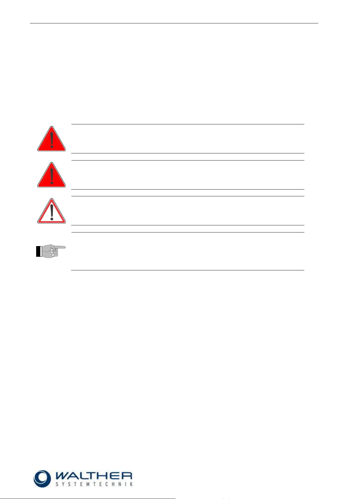
DANGER
Describes a potentially dangerous situation.
Death, grievous bodily harm or severe material damage WILL occur if the respective
measures of precaution have not been taken
WARNING
Describes a potentially dangerous situation.
Death, grievous bodily harm or severe material damage MAY occur if the respective
measures of precaution have not been taken
CAUTION
Describes a potentially dangerous situation.
Slight injuries CAN occur if the respective measures of precaution have not been
taken. This signal word is also used to describe possible property damages.
IMPORTANT
Indicates tips for usage and other particularly useful information.
No dangerous situation.
1 Introduction
1.1 Target Group of the Assembly Instructions
Operating personal
Maintenance personal
1.2 List of Signs and Symbols
The assembly instructions warn users of operations which may put their health at risk. The warnings are
indicated by combinations of text and symbols as follows:
2 Safety
2.1 General Information
The construction of this device is according to the latest technology and is absolutely reliable. The individual
components as well as the complete device are continuously checked by our quality management.
2.2 Dangers from to Residual Energy
Please instruct the operating personnel on the respective measures to be taken against the occurance of
mechanical, hydraulic, pneumatic and electric / electronic residual energies.
2.3 Warranty and Liability
According to the conditions laid down by the German Engineering Federation (VDMA), Walther Systemtechnik GmbH has a guarantee of 12 months under normal European operating conditions on its own parts
(spare parts are excluded); or according to the conditions of the manufacturer.
This guarantee can only be granted by Walther Systemtechnik GmbH, if:
the user has thorough knowledge of the content of the assembly instructions;
the user follows the instructions and notes contained in the assembly instructions;
the user does not rebuild or make changes on parts of the device without prior consent of WST Sys-
temtechnik GmbH.
Page 5

Rev. 1.0
Assembly Instructions - FSP-01 Fine-Spray Pistol with Handgrip
Page 5 of 19
Walther Systemtechnik GmbH – D 76726 Germersheim
phone: +49 (0)7274-7022-0 fax: +49 (0)7274-7022-91
http://www.walther-2000.de – info@walther-2000.de
WARNING
Do not use any solvents, cleaning liquids or coating materials containing 1,1,1 Trichloromethane or Methylene Chloride i.e. agents of the group of chlorinated hydrocarbons. These chemicals may react with aluminum, anodized or zinced parts. The chemical reaction may be explosive.
Personnel
Task
Instructed
Personnel
Personnel with Technical
Qualification
Specialist
Supervisor
Packaging, Transport
X
-
-
-
Commissioning
X
X
-
Operation
X
-
Troubleshooting, general
X
X
-
Troubleshooting
mechanical
-
X
-
-
Troubleshooting electrical
-
-
X
-
Setting up
-
X
-
-
Maintenance
-
X
-
-
Repair
-
X
X
-
Taking out of service,
Storage
-
X
X
-
2.4 Correct Use
The FSP-01 FINE-SPRAY spraying pistol is designed and constructed for finest application of thin materials,
e.g. release agents, colors or other fluids of low viscosity at room temperature. It is not suitable for spraying
aggressive fluids such as acids, alkaline solutions, cleaning agents, chemicals, etc. In case of doubt, please
contact the manufacturer.
2.5 Incorrect Use
Operating the device with insufficient knowledge about the operation, maintenance and care of the
device.
Making changes, extensions or alterations on the device that may hamper its safety without the prior
consent of Walther Systemtechnik GmbH.
Operating the device with defective safety installations or not properly attached or malfunctioning
safety devices.
Using unsuitable materials.
Handling the device while energized.
2.6 Qualification of Personnel
Only trained and instructed personnel may conduct work on the equipment.
The responsibilities of the personnel for assembly work, operation, repair work or maintenance work must be
clearly assigned to individuals!
Persons in training may work with the equipment only under supervision of an experienced person.
Page 6

Rev. 1.0
Assembly Instructions - FSP-01 Fine-Spray Pistol with Handgrip
Page 6 of 19
Walther Systemtechnik GmbH – D 76726 Germersheim
phone: +49 (0)7274-7022-0 fax: +49 (0)7274-7022-91
http://www.walther-2000.de – info@walther-2000.de
CAUTION
Use of other media can result in malfunctions, property damage, or destruction of the
machine.
3 Transport
3.1 Packaging
The type of packaging depends on the individual mode of shipping. If not separately contracted, the
packaging is in accordance with the rules and regulations of Walther Systemtechnik GmbH. This rule is in
accordance with the Federal Association for Packaging HPE.
3.2 Tasks before Transport
The following has to be done before transport:
Disconnect all power lines.
The actual transport of the incomplete device and its individual parts requires special care in order to prevent
damages from external forceful impact or careless on- and off-loading. Depending on the mode of
transportation, suitable transport and load securing has to be selected. The incomplete device will be aligned
and leveled by appropriate fastening elements.
4 Functional Description
4.1 Function
The FSP-01 Fine-Spray Pistol is designed and constructed for finest application of thin materials, e.g. release agents, colours or other fluids of low viscosity up to 50 bar material pressure. Depending on the air cap
used, this valve sprays in flat- or round-spray. Depending on the viscosity of the fluid, the application can be
adjusted individually via nozzle dimension, atomizing air pressure and material pressure. The supply of atomizing air and material takes place via two hoses.
The FSP-01 Fine-Spray Pistol has been thoroughly tested before leaving the factory. No more adjustment is
necessary prior to setting up spray operation. If fluid output, however, requires to be regulated individually,
apply needle regulator (24.1) for quantity of fluid flow. To spray with a spray gun definite volume of atomising
air and a definite pressure of materials is needed. The needle will be opened by activating the trigger and the
material flows out of from the nozzle. The air pressure atomises the material and forms it to a jet. The needle
function is: Opening by trigger and closing by spring force.
Page 7

Rev. 1.0
Assembly Instructions - FSP-01 Fine-Spray Pistol with Handgrip
Page 7 of 19
Walther Systemtechnik GmbH – D 76726 Germersheim
phone: +49 (0)7274-7022-0 fax: +49 (0)7274-7022-91
http://www.walther-2000.de – info@walther-2000.de
Weight [g]
approx. 240
Control air pressure [bar]
max. 6
Material pressure [bar]
max. 4
Weight [g]
approx. 270
Air consumption [l/min]
approx. 90 (at 3 bar and 0.5mm nozzle)
Control air pressure [bar]
max. 6
Material pressure [bar]
max. 50
CAUTION
Never point the jet at people. The wearing of eye protection is strongly recommended.
The spraying process can create noise depending on the air and fluid pressures used.
Ear protection should be worn, if required.
WARNING
Danger caused by flammable, harmful fluid. Always follow the safety instructions on the
container or the safety data sheet for the fluid.
4.2 Technical data
KLS and HVLP
With Adjusting Screw
5 Initial Start-up
5.1 Installation
Connect hoses
Material: spray medium to pistol connection “M” (26.1)
Air: spray air to pistol connection “AIR” (26.0)
Set atomizing air pressure via reducing valve (not part of the spray gun).
Set material pressure via a second reducing valve (not part of the spray gun). The supply pressure
and the spray air pressure will determine the drop-size of the spray medium in the jet.
6 Operation
6.1 General Information
This device may only be operated if the safety-related equipment is permanently effective and not suspended during operation or altered in its intended effectiveness.
6.2 Operating Instructions
Page 8

Rev. 1.0
Assembly Instructions - FSP-01 Fine-Spray Pistol with Handgrip
Page 8 of 19
Walther Systemtechnik GmbH – D 76726 Germersheim
phone: +49 (0)7274-7022-0 fax: +49 (0)7274-7022-91
http://www.walther-2000.de – info@walther-2000.de
IMPORTANT
After the spraying operation the pistol should be briefly blown free of any residues, in
order that the nozzle does not clog up and hamper the atomizing process.
IMPORTANT
The spraying material amount can be adjusted to the individual requirements by turning
the regulating screw (24.1.0) (if provided):
Right turn: decrease in material amount
Left turn: increase in material amount
Nozzle and needle can be damaged by wrong handling. Only decrease the material
flow (by a right turn of the regulating knob) if material spills out. Do not turn the regulating knob further to the right after the nozzle is closed!
Activate releasing trigger (19.1). Spray operation starts. You will notice that you receive so called “pre-air”
prior to opening fluid flow when pulling the trigger. When releasing the trigger you still have “purging-air” after
needle has closed nozzle and fluid flow was stopped. This prevents that fluid forms drops instead of the desired atomization.
Depending on the viscosity of the medium, the following nozzle bores are available: 0.2 ; 0.3 ; 0.5 ; 0.8 and
1.0 mm (only one size of air cap is required for all standard nozzles).
The standard spray pistol is equipped with a flat-spray cap 3.1.1. A round-spray cap 3.1.2 can be used and
ordered as an accessory.
Flat-spray air caps can be individually positioned horizontally, vertically etc. by means of turning the air cap.
The spraying air must be controlled as such, that it is switched on before the needle opens and is switched
off after the nozzle has closed again (resulting in minimum maintenance work).
The valves can be controlled for intermittent or continuous use. According to the individual application, the
control air must be adjusted to the operating cycles and to the higher or lower material pressures. 30 tacts
per second can be reached under appropriate operating conditions (material pressure, control air pressure,
needle stroke, short conductions)
It is harmless to leave fluid in the valve during longer standstills, if system stays under pressure (no connection to outside air).
Page 9

Rev. 1.0
Assembly Instructions - FSP-01 Fine-Spray Pistol with Handgrip
Page 9 of 19
Walther Systemtechnik GmbH – D 76726 Germersheim
phone: +49 (0)7274-7022-0 fax: +49 (0)7274-7022-91
http://www.walther-2000.de – info@walther-2000.de
IMPORTANT
Please follow the Operating Instructions!
IMPORTANT
Please follow the maintenance instructions!
IMPORTANT
Please follow the maintenance instructions!
CAUTION
Before starting any maintenance or repair work, ensure that all air-operated tools are
depressurized and disconnected from the air supply.
Before opening the spray valve it must be disconnected from the air and fluid supply.
Otherwise, ejected components can cause injuries
7 Taking out of Service
7.1 Short Interruption
A short interruption (15 min or more) has to be followed by a fine spraying.
7.2 Long-term Interruption
The following has to be observed for a long-term interruption of the device/machine:
Depressurize material supply lines
Take off air cap (3) and clean nozzle (2) with a special thinner and a soft cloth. Make sure that no cloth
fibers are left on the nozzle tip.
7.3 Final Shutdown of Device
The following is important for a shutdown of the machine / device:
Clean spray pistol with a special thinner.
8 Maintenance and Repair
8.1 General Information
The FSP-01 Fine-Spray Pistols are high precision tools. Always keep clean and observe minimum
instructions to maintain a long life of the valve. Always use clean and filtered material only. The control air
must also be clean and should be slightly oiled, if necessary. Maintenance also depends on the individual
operating conditions and the type of media used.
Particularly when using the spraying pistol as a color marking device, the spraying cap should be removed
before longer standstills. The spraying nozzle should be cleaned with a soft cloth and the special dilution.
Please make sure that no cloth fibers remain on the nozzle tip. Then spray the valve free by keeping the
manual switch of PLC control or the auxiliary switch on the 3/2-way solenoid valve (green button) pressed for
some time.
Page 10

Rev. 1.0
Assembly Instructions - FSP-01 Fine-Spray Pistol with Handgrip
Page 10 of 19
Walther Systemtechnik GmbH – D 76726 Germersheim
phone: +49 (0)7274-7022-0 fax: +49 (0)7274-7022-91
http://www.walther-2000.de – info@walther-2000.de
IMPORTANT
Hold the spraying valve downwards when doing so, in order that the medium does not
flow into the air ducts. Collect the escaping medium in a container and dispose of it
appropriately.
8.2 Cleaning
Only use soft brushes for outside cleaning of the nozzle tips. Never use metal tools with sharp edges. Before
starting any repair or maintenance work, make sure that the work place as well as the device itself are thoroughly cleaned. Do not start any repair work on the installed device. Remove the device from the machines
first. (Disconnect from the air and fluid supply!)
To clean the gun, spray solvent until pure solvent leaves nozzle.
Do not submerge entire gun in solvent.
For longer working interruptions it is advisable to clean air cap and nozzle by putting these parts only
into solvent. If necessary, use soft brush.
To clean small drill holes, use our special nozzle cleaning needles or a soft brush.
Moving parts and threads should always be greased slightly and regularly.
8.3 Replacing the Nozzle Set
A nozzle set includes needle (1.1.1), nozzle (2.1.1) and air cap (3.1.1). If nozzle size is to be changed,
always change all three parts. Change the complete set also when only one of the parts is defect.
Remove screw (21.1)
Pull out valve spring (20.1)
Pull out needle/valve cartridge
Unscrew the collar ring (4.1.1), remove air cap (3.1.1 or 3.1.2)
Unscrew nozzle (2.1.1)
Re-assemble in reverse order.
8.4 Replacing the Needle-Valve Unit
Remove screw (21.1)
Pull out valve spring (20.1)
Pull out needle/valve cartridge
Unscrew valve lock (18.1)
Pull out needle spring (17.1)
Pull out needle (1.1.1)
Re-assemble in reserve order. OBSERVE!!!
Needle nuts (16.1) must be counter-screwed on the needle 1.1.1 in such a way that “pre-air” (when trigger is
released) and “purging-air” (when spraying process is finished) work properly.
The correct position of needle nuts on the needle or the extension needle is 8.8 – 9.0mm from the end of the
needle. This does also apply for a retrograde mounting of extension needles.
Page 11

Rev. 1.0
Assembly Instructions - FSP-01 Fine-Spray Pistol with Handgrip
Page 11 of 19
Walther Systemtechnik GmbH – D 76726 Germersheim
phone: +49 (0)7274-7022-0 fax: +49 (0)7274-7022-91
http://www.walther-2000.de – info@walther-2000.de
8.5 Spare Parts
IMPORTANT
Only use original spare parts from the manufacturer!
Wrong or defective spare parts from other manufacturers can damage the device. If
other than original spare parts of the manufacturer will be used, all obligations from the
manufacturer or his sales partners, such as guarantees, service contracts etc will be
forfeited without further notice.
Walther Systemtechnik GmbH
Hockenheimer Straße 3
D-76726 Germersheim
Germany
phone ++49(0)7274-7022-0
fax ++49(0)7274-7022-91
e-mail info@walther-2000.de
internet www.walther-2000.de
IMPORTANT
First check all supply lines for connectivity and serviceability.
8.6 Customer Service / Support
9 Troubleshooting
9.1 General Information
In case of serious problems that cannot be resolved, please contact the Walther Systemtechnik GmbH customer service.
9.2 Cases of Failure
Drops form on the trigger
The needle gasket (10.1) is either worn or loose and must slightly be retightened. For that purpose remove
needle/valve cartridge (see section 6.4). Then unscrew screw (12.2) and take out needle driver (12.1). Using
a small screw driver turn stuffing box (11.1) gently clockwise and try if needle is sliding smoothly again within
the tightening gasket.
Drops form on the nozzle
Either the needle or the nozzle is worn and should be replaced. Or needle is not closed properly because of
particle residues within nozzle. Clean the needle/valve cartridge with solvent (see section 6.2).
Uneven and not steady spray jet
Make sure that nozzle is screwed in tight. Other reason could also be dirt residue within air cap. Clean air
cap with solvent.
Air is blowing constantly although trigger is released
O-Ring (13.1) and/or washer (14.1) are worn and must be exchanged. Or needle nuts are not counterscrewed in correct position (see section 6.4).
Page 12

Rev. 1.0
Assembly Instructions - FSP-01 Fine-Spray Pistol with Handgrip
Page 12 of 19
Walther Systemtechnik GmbH – D 76726 Germersheim
phone: +49 (0)7274-7022-0 fax: +49 (0)7274-7022-91
http://www.walther-2000.de – info@walther-2000.de
SPRAY IMAGE
PROBLEM
CAUSE
ACTION
Normal Spray Image (Flat jet)
Normal Spray Image (Round jet)
Spray image shaped
too much
upwards and
downwards
Soiled
air cap
Soiled
nozzle
Clean nozzles
Spray image too much
left-sided or right-sided
Soiled
air cap
Soiled
nozzle
Clean nozzles
Heavy application in the
middle of the spray image
Too much material
Material too thick
Reduce
material supply
Dilute material
Split
spray image
Too little material
Pressure flat jet too
high
Increase
material supply
Increase pressure
for round jet
9.3 Spray Image/ Type of Defect
Page 13

Rev. 1.0
Assembly Instructions - FSP-01 Fine-Spray Pistol with Handgrip
Page 13 of 19
Walther Systemtechnik GmbH – D 76726 Germersheim
phone: +49 (0)7274-7022-0 fax: +49 (0)7274-7022-91
http://www.walther-2000.de – info@walther-2000.de
10 Appendix
10.1 Spare Parts Drawing for FSP-01 (KLS and HVLP)
Page 14

Rev. 1.0
Assembly Instructions - FSP-01 Fine-Spray Pistol with Handgrip
Page 14 of 19
Walther Systemtechnik GmbH – D 76726 Germersheim
phone: +49 (0)7274-7022-0 fax: +49 (0)7274-7022-91
http://www.walther-2000.de – info@walther-2000.de
Draw. No. Article No. Qty. Description
1.1.1 * 1 needle, stainless steel (part no. see overleaf)
2.1.1 * 1 nozzle, SM, stainless steel (part no. see overleaf)
3.1.1 * 1 air cap, flat spray HVLP (part no. see overleaf)
3.1.2 * 1 air cap, round spray HVLP (part no. see overleaf)
4.1.1 97410028 1 collar ring
4.1.2 97410014 1 protecting ring 19mm (optional)
5.1 97510010 1 pistol body
9.1 97610036 1 screw
9.2 97410013 1 cap nut
10.1 97640062 1 needle gasket (PTFE)
11.1 97810002 1 stuffing box
12.1 97320002 1 needle driver
12.2 97610035 1 screw
13.1 97640036 1 o-ring
14.1 97640008 1 washer
15.1 97380010 1 air valve
16.1 97410026 2 needle nut
17.1 97820005 1 needle spring
18.1 97610001 1 valve lock
19.1 97190006 1 trigger
20.1 97820024 1 valve spring
21.1 97220057 1 screw
21.2 97220150 1 blocked lock (optional)
23.1 97410008 1 counter nut
24.1 97610029 1 needle regulator
26.0 97220021 2 hose socket, complete
26.2 97640080 2 washer
26.3 97220055 2 hose socket
26.4 97410030 2 nut
27.1 97500019 1 buckling guard, complete (optional)
28.1 97910004 1 hook (optional)
IMPORTANT
Please always indicate the inscribed serial numbers when ordering spare parts!
10.1.1 Spare Parts List for FSP-01 (KLS and HVLP)
* These article numbers can be found on the following pages.
Page 15

Rev. 1.0
Assembly Instructions - FSP-01 Fine-Spray Pistol with Handgrip
Page 15 of 19
Walther Systemtechnik GmbH – D 76726 Germersheim
phone: +49 (0)7274-7022-0 fax: +49 (0)7274-7022-91
http://www.walther-2000.de – info@walther-2000.de
*needle KLS *nozzle KLS
Draw No. Article No. Description Draw No. Article No. Description
1.1.1 97111074 needle 0.3mm 2.1.1 97210104 nozzle 0.3mm
1.1.1 97110358 needle 0.5mm 2.1.1 97210105 nozzle 0.5mm
1.1.1 97110360 needle 0.8/1.0mm 2.1.1 97210106 nozzle 0.8mm
1.1.1 97110645 needle 1.5mm 2.1.1 97210107 nozzle 1.0mm
2.1.1 97210108 nozzle 1.5mm
* air cap / flat spray 60° KLS (standard)
Draw No. Article No. Description
3.1.1 97310081 for nozzle 0.2 - 1.0mm
3.1.1 97310082 for nozzle 1.2 - 1.5mm
* air cap / flat spray 90° KLS
Draw No. Article No. Description
3.1.1 97310108 for nozzle 0.2 - 1.0mm
* air cap / round spray 15° KLS
Draw No. Article No. Description
3.1.2 97310084 for nozzle 0.2 - 1.0mm
3.1.2 97310085 for nozzle 1.2 - 1.5mm
10.1.2 Needles, Nozzles and Air Caps for FSP-01 (KLS)
Page 16

Rev. 1.0
Assembly Instructions - FSP-01 Fine-Spray Pistol with Handgrip
Page 16 of 19
Walther Systemtechnik GmbH – D 76726 Germersheim
phone: +49 (0)7274-7022-0 fax: +49 (0)7274-7022-91
http://www.walther-2000.de – info@walther-2000.de
*needle *nozzle SM
Draw No. Article No. Description Draw No. Article No. Description
1.1.1 97110073 needle 0.2/0.3mm 2.1.1 97210070 nozzle SM 0.2mm
1.1.1 97110074 needle 0.5mm 2.1.1 97210071 nozzle SM 0.3mm
1.1.1 97110075 needle 0.8mm 2.1.1 97210072 nozzle SM 0.5mm
1.1.1 97110076 needle 1.0mm 2.1.1 97210073 nozzle SM 0.8mm
2.1.1 97210074 nozzle SM 1.0mm
* air cap / flat spray 60° (standard) HVLP
Draw No. Article No. Description
3.1.1 97310268 air cap, flat spray HVLP, 0.2 - 0.5mm
3.1.1 97310269 air cap, flat spray HVLP, 0.8 - 1.0mm
* air cap / round spray 15° HVLP
Draw No. Article No. Description
3.1.2 97310270 air cap, round spray HVLP, 0.2 - 0.5mm
3.1.2 97310034 air cap, round spray HVLP, 0.8 - 1.0mm
10.1.3 Needles, Nozzles and Air Caps for FSP-01 (HVLP)
Page 17

Rev. 1.0
Assembly Instructions - FSP-01 Fine-Spray Pistol with Handgrip
Page 17 of 19
Walther Systemtechnik GmbH – D 76726 Germersheim
phone: +49 (0)7274-7022-0 fax: +49 (0)7274-7022-91
http://www.walther-2000.de – info@walther-2000.de
26.0
26.1
4.1.1
3.1.1
4.1.2
3.1.2 12.1
9.1
19.1
2.1.1
5.1
9.2 12.2
10.1
11.1
13.1
14.1
15.1
20.1
1.1.1
16.1
17.1
18.1
28.1
(optional)
26.2
26.3
26.4
21.1
21.2
21.3
21.4
10.2 Spare Parts Drawing for FSP-01 HD with Regulating Screw
Page 18

Rev. 1.0
Assembly Instructions - FSP-01 Fine-Spray Pistol with Handgrip
Page 18 of 19
Walther Systemtechnik GmbH – D 76726 Germersheim
phone: +49 (0)7274-7022-0 fax: +49 (0)7274-7022-91
http://www.walther-2000.de – info@walther-2000.de
Draw. No. Article No. Qty. Description
1.1.1 * 1 needle, stainless steel (part no. see overleaf)
2.1.1 * 1 nozzle, stainless steel (part no. see overleaf)
3.1.1 * 1 air cap, flat spray (part no. see overleaf)
3.1.2 * 1 air cap, round spray (part no. see overleaf)
4.1.1 97410028 1 collar ring
4.1.2 97410014 1 protecting ring 19mm (optional)
5.1 97510010 1 pistol body
9.1 97610036 1 screw
9.2 97410013 1 cap nut
10.1 97640062 1 needle gasket (PTFE)
11.1 97810002 1 stuffing box
12.1 97320002 1 needle driver
12.2 97610035 1 screw
13.1 97640036 1 o-ring
14.1 97640008 1 washer
15.1 97380010 1 air valve
16.1 97410026 2 needle nut
17.1 97820005 1 needle spring
18.1 97610001 1 valve lock
19.1 97190006 1 trigger
20.1 97820020 1 valve spring 1,1 x22mm
21.0 97800087 1 regulating screw W3, complete
21.1 97610069 1 regulating spindle, 6x19mm, M6
21.2 97220051 1 screw 16 x 33mm
21.3 97640001 1 o-ring 7,65 x 1,78 / viton
21.4 97320044 1 regulating cap, 13x22mm, M6
26.0 97220021 1 hose socket, complete
26.2 97640080 1 washer
26.3 97220055 1 hose socket
26.4 97410030 1 nut
26.1 97220205 1 high pressure fitting, stainless steel, M5 - 1/4"
28.1 97910004 1 hook (optional)
IMPORTANT
Please always indicate the inscribed serial numbers when ordering spare parts!
10.2.1 Spare Parts List for FSP-01 HD with Regulating screw
* These article numbers can be found on the following pages.
Page 19

Rev. 1.0
Assembly Instructions - FSP-01 Fine-Spray Pistol with Handgrip
Page 19 of 19
Walther Systemtechnik GmbH – D 76726 Germersheim
phone: +49 (0)7274-7022-0 fax: +49 (0)7274-7022-91
http://www.walther-2000.de – info@walther-2000.de
10.2.2 Needles, Nozzles and Air Caps for FSP-01 HD with Regulating Screw
*needle *nozzle
Draw No. Article No. Description Draw No. Article No. Description
1.1.1 97110073 needle 0.2/0.3mm 2.1.1 97210063 nozzle 0.3mm
1.1.1 97110074 needle 0.5mm 2.1.1 97210064 nozzle 0.5mm
1.1.1 97110075 needle 0.8mm 2.1.1 97210065 nozzle 0.8mm
1.1.1 97110076 needle 1.0mm 2.1.1 97210066 nozzle 1.0mm
1.1.1 97110077 needle 1.2mm 2.1.1 97210067 nozzle 1.2mm
1.1.1 97110078 needle 1.5mm 2.1.1 97210068 nozzle 1.5mm
2.1.2 97210069 nozzle 0.2mm
*air cap / flat spray 45°
Draw No. Article No. Description
3.1.1 97310038 for nozzle 0.2 - 1.0mm
3.1.1 97310039 for nozzle 1.2 - 1.5mm
* air cap / flat spray 60° (standard)
Draw No. Article No. Description
3.1.1 97310032 for nozzle 0.2 - 1.0mm
3.1.1 97310033 for nozzle 1.2 - 1.5mm
* air cap / flat spray 90°
Draw No. Article No. Description
3.1.1 97310036 for nozzle 0.2 - 1.0mm
3.1.1 97310037 for nozzle 1.2 - 1.5mm
* air cap / round spray 15°
Draw No. Article No. Description
3.1.2 97310034 for nozzle 0.2 - 1.0mm
3.1.2 97310035 for nozzle 1.2 - 1.5mm
 Loading...