

Page 1

W600/
W
900 Modbus
Instruction Manual
WAL C HE M, Iwaki America Inc.
Five Boynton Road Hopping Brook Park Holliston, MA 01746 USA :
TEL: 508-429-1110 WEB: www.walchem.com
Page 2

Notice
© 2018 WALCHEM, Iwaki America Inc. (hereinafter “Walchem”)
5 Boynton Road, Holliston, MA 01746 USA
(508) 429-1110
All Rights Reserved
Printed in USA
Proprietary Material
The information and descriptions contained herein are the property of WALCHEM. Such information and
descriptions may not be copied or reproduced by any means, or disseminated or distributed without the
express prior written permission of WALCHEM, 5 Boynton Road, Holliston, MA 01746.
This document is for information purposes only and is subject to change without notice.
Statement of Limited Warranty
WALCHEM warrants equipment of its manufacture, and bearing its identification to be free from defects in
workmanship and material for a period of 24 months for electronics and 12 months for mechanical parts and
electrodes from date of delivery from the factory or authorized distributor under normal use and service and
otherwise when such equipment is used in accordance with instructions furnished by WALCHEM and for the
purposes disclosed in writing at the time of purchase, if any. WALCHEM’s liability under this warranty shall
be limited to replacement or repair, F.O.B. Holliston, MA U.S.A. of any defective equipment or part which,
having been returned to WALCHEM, transportation charges prepaid, has been inspected and determined by
WALCHEM to be defective. Replaceable elastomeric parts and glass components are expendable and are not
covered by any warranty.
THIS WARRANTY IS IN LIEU OF ANY OTHER WARRANTY, EITHER EXPRESS OR IMPLIED, AS TO
DESCRIPTION, QUALITY, MERCHANTABILITY, FITNESS FOR ANY PARTICULAR PURPOSE OR USE,
OR ANY OTHER MATTER.
180676 Rev F
October 2018
Page 3

Table of Contents
1.0 SCOPE ............................................................................................................................................................... 1
2.0 INTRODUCTION ................................................................................................................................................ 1
3.0 OVERVIEW ........................................................................................................................................................ 1
3.1 Modbus Settings ..................................................................................................................................................................... 2
4.0 MODBUS/TCP DRIVER ...................................................................................................................................... 2
4.1 Modbus/TCP Protocol ............................................................................................................................................................ 2
4.1.1 MBAP Header .................................................................................................................................................................... 2
4.1.2 Protocol Data Unit ............................................................................................................................................................. 3
4.1.3 Modbus/TCP Function Codes ............................................................................................................................................ 3
4.1.3.1 Function Code 1, Read Coils ..................................................................................................................................... 4
4.1.3.2 Function Code 2, Read Discrete Inputs .................................................................................................................... 4
4.1.3.3 Function Code 3, Read Holding Registers ................................................................................................................ 5
4.1.3.4 Function Code 4, Read Input Registers .................................................................................................................... 5
4.1.3.5 Function Code 5, Write Single Coil ........................................................................................................................... 6
4.1.3.6 Function Code 6, Write Single Holding Register ...................................................................................................... 6
4.1.3.7 Function Code 16, Write Multiple Holding Registers ............................................................................................... 7
4.1.4 Modbus/TCP Exception Error Codes .................................................................................................................................. 7
4.2 TCP/IP Interface ...................................................................................................................................................................... 8
4.3 Data Refresh ........................................................................................................................................................................... 8
4.4 Data Encoding ........................................................................................................................................................................ 8
4.4.1 Coils and Discrete Inputs ................................................................................................................................................... 8
4.4.1.1 Boolean .................................................................................................................................................................... 8
4.4.2 Holding Register and Input Registers ................................................................................................................................. 8
4.4.2.1 16-Bit Word (Boolean) ............................................................................................................................................. 8
4.4.2.2 16-Bit Word (Bitfield) ............................................................................................................................................... 9
4.4.2.3 16-Bit Word (Status) ................................................................................................................................................ 9
4.4.2.4 16-Bit Word (Integer) ............................................................................................................................................... 9
4.4.2.5 32-Bit Value (Integer) ............................................................................................................................................... 9
4.4.2.6 32-Bit Value (Float) .................................................................................................................................................. 9
4.4.2.7 32-Bit Inverse Data Format (Integer or Float) ........................................................................................................ 10
5.0 DATA DICTIONARY .......................................................................................................................................... 10
5.1 Addressing (0- or 1-Based) ................................................................................................................................................... 10
5.2 Address Maps ....................................................................................................................................................................... 10
5.2.1 W600 Controller – I/O Channel Address Maps ................................................................................................................ 11
5.2.2 W900 Controller – I/O Channel Address Maps ................................................................................................................ 12
5.2.3 Alternate Address Maps .................................................................................................................................................. 14
5.3 Type-Specific Address Map .................................................................................................................................................. 15
5.3.1 System Address Map ....................................................................................................................................................... 15
5.3.2 Network Address Map ..................................................................................................................................................... 16
5.3.3 Sensor Input Address Maps ............................................................................................................................................. 17
5.3.3.1 Sensor Input (all types except Analog Input Flowmeter) Address Map ................................................................. 17
5.3.3.2 Analog Input Flowmeter Address Map .................................................................................................................. 18
5.3.4 Digital Input Address Maps .............................................................................................................................................. 19
5.3.4.1 Digital Input / DI State Type Address Map ............................................................................................................. 19
5.3.4.2 Digital Input / Contacting Flow Meter Type Address Map ..................................................................................... 20
5.3.4.3 Digital Input / Paddlewheel Flow Meter Type Address Map ................................................................................. 21
5.3.4.4 Digital Input / DI Counter Type Address Map ........................................................................................................ 22
5.3.4.5 Digital Input / Flow Monitor Type Address Map .................................................................................................... 23
5.3.5 Virtual Input Address Maps ............................................................................................................................................. 24
5.3.5.1 Virtual Input / Calculation & Raw Value Type Address Map .................................................................................. 24
Page 4

5.3.5.2 Virtual Input / Redundant Sensor Type Address Map ........................................................................................... 25
5.3.5.3 Virtual Input / Disturbance Type Address Map ..................................................................................................... 26
5.3.6 Relay Output Address Maps ............................................................................................................................................ 27
5.3.6.1 Relay Output / Manual Control Mode Address Map ............................................................................................. 27
5.3.6.2 Relay Output / On/Off & On/Off Disturbance Control Mode Address Map .......................................................... 28
5.3.6.3 Relay Output / Dual Setpoint Control Mode Address Map .................................................................................... 29
5.3.6.4 Relay Output / Time Proportional Control Mode Address Map ............................................................................ 30
5.3.6.5 Relay Output / Intermittent Sampling Control Mode Address Map ...................................................................... 31
5.3.6.6 Relay Output / Bleed And Feed Control Mode Address Map ................................................................................ 32
5.3.6.7 Relay Output / Bleed Then Feed Control Mode Address Map ............................................................................... 33
5.3.6.8 Relay Output / Flow Timer Control Mode Address Map ....................................................................................... 34
5.3.6.9 Relay Output / Counter Timer Control Mode Address Map .................................................................................. 35
5.3.6.10 Relay Output / Target PPM Control Mode Address Map ....................................................................................... 36
5.3.6.11 Relay Output / PPM By Volume Control Mode Address Map ................................................................................ 37
5.3.6.12 Relay Output / Flow Meter Ratio Control Mode Address Map .............................................................................. 38
5.3.6.13 Relay Output / Volumetric Blend Control Mode Address Map .............................................................................. 39
5.3.6.14 Relay Output / Percent Timer Control Mode Address Map ................................................................................... 40
5.3.6.15 Relay Output / Event Timer Control Mode Address Map ...................................................................................... 41
5.3.6.16 Relay Output / Biocide Timer Control Mode Address Map ................................................................................... 42
5.3.6.17 Relay Output / Spike Control Mode Address Map ................................................................................................. 43
5.3.6.18 Relay Output / Probe Wash Control Mode Address Map ...................................................................................... 44
5.3.6.19 Relay Output / Plating Control Mode Address Map .............................................................................................. 45
5.3.6.20 Relay Output / Plating Follow Control Mode Address Map ................................................................................... 46
5.3.6.21 Relay Output / Lag Output Control Mode Address Map........................................................................................ 47
5.3.6.22 Relay Output / Alarm Control Mode Address Map ................................................................................................ 48
5.3.7 Pulse Relay Output Address Maps ................................................................................................................................... 49
5.3.7.1 Pulse Relay Output / Manual Control Mode Address Map .................................................................................... 49
5.3.7.2 Pulse Relay Output / Pulse Proportional Control Mode Address Map .................................................................. 50
5.3.7.3 Pulse Relay Output / Flow Proportional Control Mode Address Map ................................................................... 51
5.3.7.4 Pulse Relay Output / Pulse PID Control Mode Address Map ................................................................................. 52
5.3.7.5 Pulse Relay Output / Pulse Disturbance Control Mode Address Map ................................................................... 53
5.3.7.6 Pulse Relay Output / Lag Output Control Mode Address Map .............................................................................. 54
5.3.8 Analog Output Address Maps .......................................................................................................................................... 55
5.3.8.1 Analog Output / Manual Control Mode Address Map ........................................................................................... 55
5.3.8.2 Analog Output / Retransmit Mode Address Map .................................................................................................. 56
5.3.8.3 Analog Output / Proportional Control Mode Address Map ................................................................................... 57
5.3.8.4 Analog Output / Flow Proportional Control Mode Address Map .......................................................................... 58
5.3.8.5 Analog Output / PID Control Mode Address Map ................................................................................................. 59
5.3.8.6 Analog Output / Disturbance Control Mode Address Map .................................................................................... 60
5.3.8.7 Analog Output / Lag Output Control Mode Address Map ..................................................................................... 61
5.3.9 Alternate Address Maps .................................................................................................................................................. 62
5.3.9.1 Alternate Sensor Input Address Map ..................................................................................................................... 62
5.3.9.2 Alternate Digital Input Address Map ..................................................................................................................... 63
5.3.9.3 Alternate Virtual Input Address Map ..................................................................................................................... 64
5.3.9.4 Alternate Relay Output Address Map .................................................................................................................... 65
5.3.9.5 Alternate Analog Output Address Map ................................................................................................................. 66
5.3.9.6 Alternate Control Output Address Map ................................................................................................................. 67
5.4 Status Register Codes ........................................................................................................................................................... 68
5.5 Alarm Bitfields ...................................................................................................................................................................... 70
5.5.1 System Alarm Bitfield ...................................................................................................................................................... 70
5.5.2 Network Alarm Bitfield .................................................................................................................................................... 70
5.5.3 Sensor Input Alarm Bitfield ............................................................................................................................................. 71
5.5.4 Digital Input Alarm Bitfield .............................................................................................................................................. 71
5.5.5 Virtual Input Alarm Bitfield .............................................................................................................................................. 72
5.5.6 Relay & Control Output Alarm Bitfield ............................................................................................................................ 72
5.5.7 Analog Output Alarm Bitfield .......................................................................................................................................... 73
Page 5

1.0 SCOPE
This document is a User Interface Specification for the Walchem Modbus/TCP product feature for W600
and W900 Controllers. It contains mapping of the various dynamic variables to their Modbus/TCP
address locations.
This document supports the Modbus/TCP feature on controller software versions 3.01 and higher.
2.0 INTRODUCTION
The Modbus/TCP feature allows the Walchem controller to communicate with PC-based applications
such as WonderWare and Intellution HMI/SCADA programs, Building Energy Management systems,
Distributed Control Systems (DCS), as well as stand-alone HMI devices.
The controller is a Modbus Server, meaning that it can respond to requests from the HMI device. The
controller cannot initiate the flow of information. For example, it will not immediately send a new alarm
message. It will wait until the HMI device requests the current data contained in specific address
locations.
If the HMI device does not directly support the Modbus/TCP protocol, then a protocol translation
gateway may be required to convert from Modbus/TCP to a protocol that the device supports. Please
note that Modbus/RTU requires a serial interface, not Ethernet, and therefore is not directly compatible
with the Walchem controller.
3.0 OVERVIEW
Modbus/TCP, also known as Modbus TCP/IP, is a form of Modbus that uses the TCP/IP layers as a base
for controlling the communications between different devices. This is not to be confused with Modbus
over TCP/IP, which Walchem controllers do not support.
The Modbus/TCP protocol supports multiple types of data transactions, from reading single bits per
transaction, to advanced object-oriented operations. However, to ensure the most compatible system
available, only a basic subset of these functions is supported in the controller.
The official Modbus/TCP protocol supports data addresses 5 digits in length. A de facto extended
standard exists which supports data addresses 6 digits in length. However, to ensure compatibility, the
Modbus/TCP feature supports only 5-digit data address system.
The Modbus/TCP feature supports reading and writing of single-bit Coils and 16-bit Holding Registers, as
well as read-only single-bit Discrete Inputs and 16-bit Input Registers. These data formats allow the
controller to establish blocks that contain all the process variables, set points, alarms, and input/output
status values that are made public to a Modbus/TCP client. These blocks of data are packaged so that it
can be read in 8-bit chunks (for a group of up to 8 Coils or Discrete Inputs) or 16-bit chunks (for a single
Holding Register or Input Register), regardless of the type of data within it. In the following sections, the
formatting, storing, and reading of this data are described.
1
Page 6

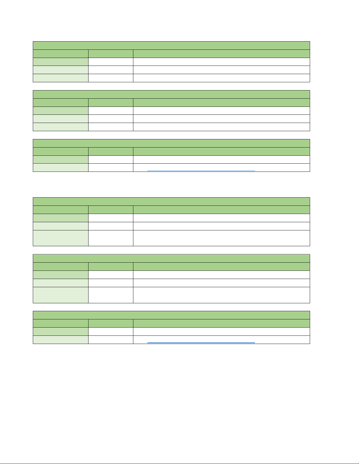
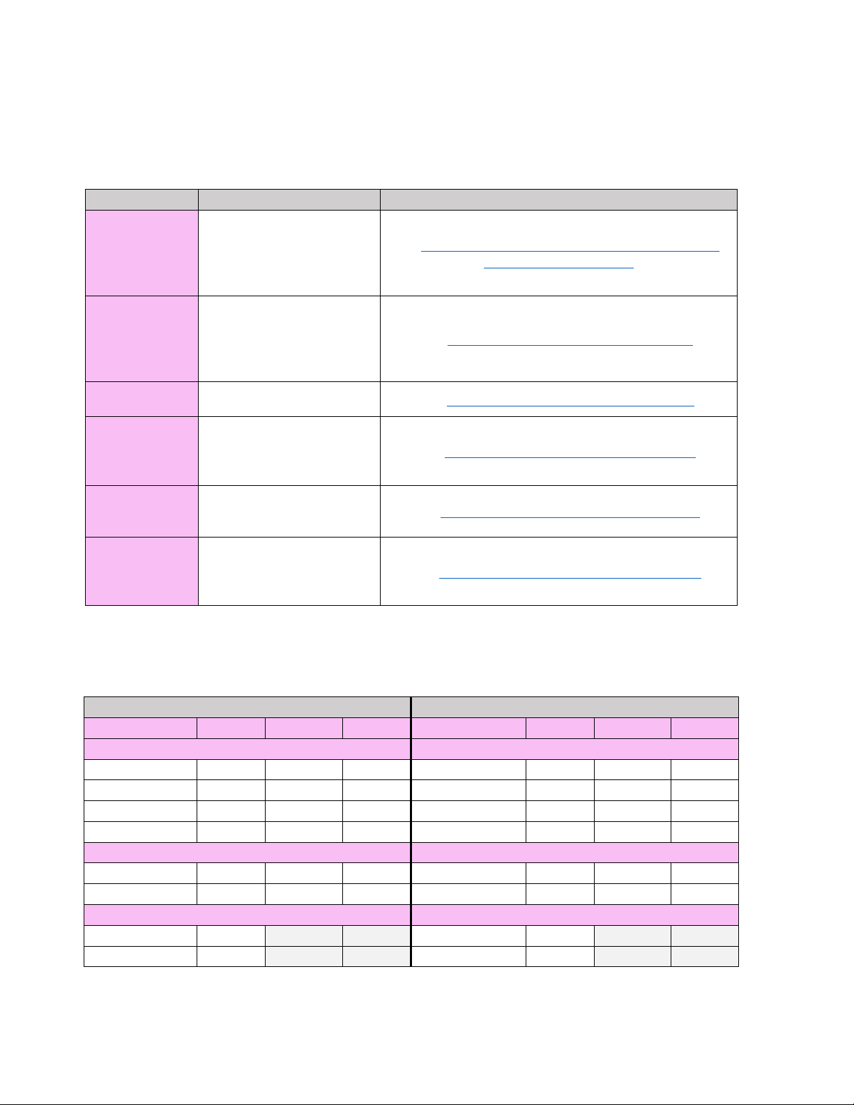
3.1 Modbus Settings
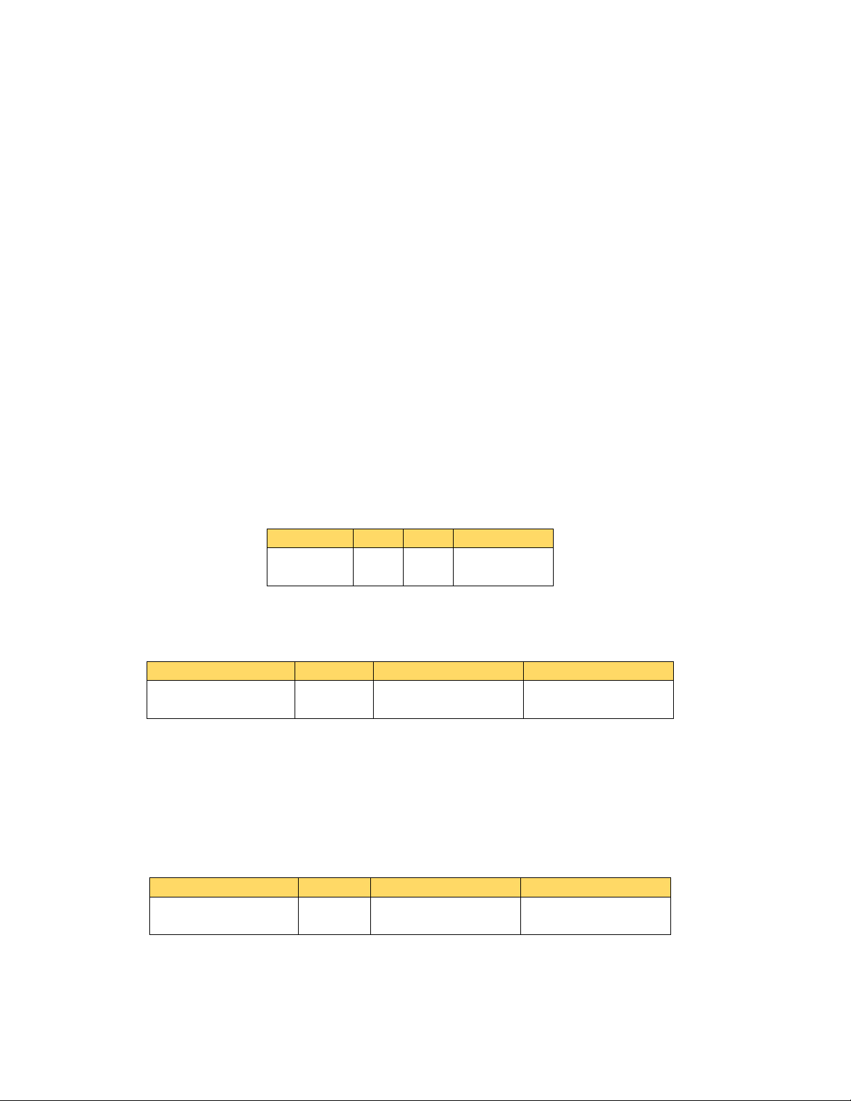
Modbus Application Protocol (MBAP)
Header
Modbus Application Protocol (MBAP) Header
Name
Size
Description
Identification of Request/Response transaction.
Copied from request to response
Protocol Identifier
2 bytes
0 = Modbus protocol.
Length
2 bytes
Number of following bytes (includes the Unit Identifier and PDU)
Identification of Remote Device.
Can be used for broadcasting (unsupported).
Settings relating to the Modbus/TCP feature can be configured in the Remote Communication
Configuration Menu.
The ‘Verbose Logging’ setting is used to generate an Event log entry for every Modbus message into and
out of the controller. The information may be used in conjunction with an HMI log when
troubleshooting communications during commissioning. However, the additional logging adds a
significant load on the controller’s systems. Therefore, this feature should only be enabled temporarily
while actively troubleshooting communications. The setting automatically reverts to Disabled when the
controller is restarted.
Detailed information on the Remote Communication Configuration Menu can be found in the controller
Instruction Manual.
4.0 MODBUS/TCP DRIVER
4.1 Modbus/TCP Protocol
The Modbus protocol, as well as the Modbus/TCP variant, is well documented in the specifications
which are available at http://www.modbus.org
supporting and organizing the Modbus protocol.
The Modbus/TCP Application Data Unit (ADU) consists of 2 distinct sections:
, a website established by the Modbus Organization for
Protocol Data Unit (PDU)
The total size of the ADU is between 9 and 263 bytes, depending on the function code and number of
data addresses requested.
4.1.1 MBAP Header
The Modbus/TCP extension adds 7 additional bytes to the original Modbus protocol, which allows for
the transport over the TCP/IP layers. These 7 bytes make up the MBAP Header:
Transaction Identifier 2 bytes
Unit Identifier 1 byte
The Unit Identifier has a special consideration in the Modbus/TCP implementation. If the value is 0, then
the request is a broadcast message and the packet will be processed, but no response will be generated.
If the value is non-zero, the packet will be processed and a response will be returned.
Normally the Slave ID, which is not present in the Modbus/TCP protocol, will be set in the HMI client
software to 1. The broadcast Unit Identifier address is not supported by the controller; all supported
function codes require a response message at all times.
2
Page 7

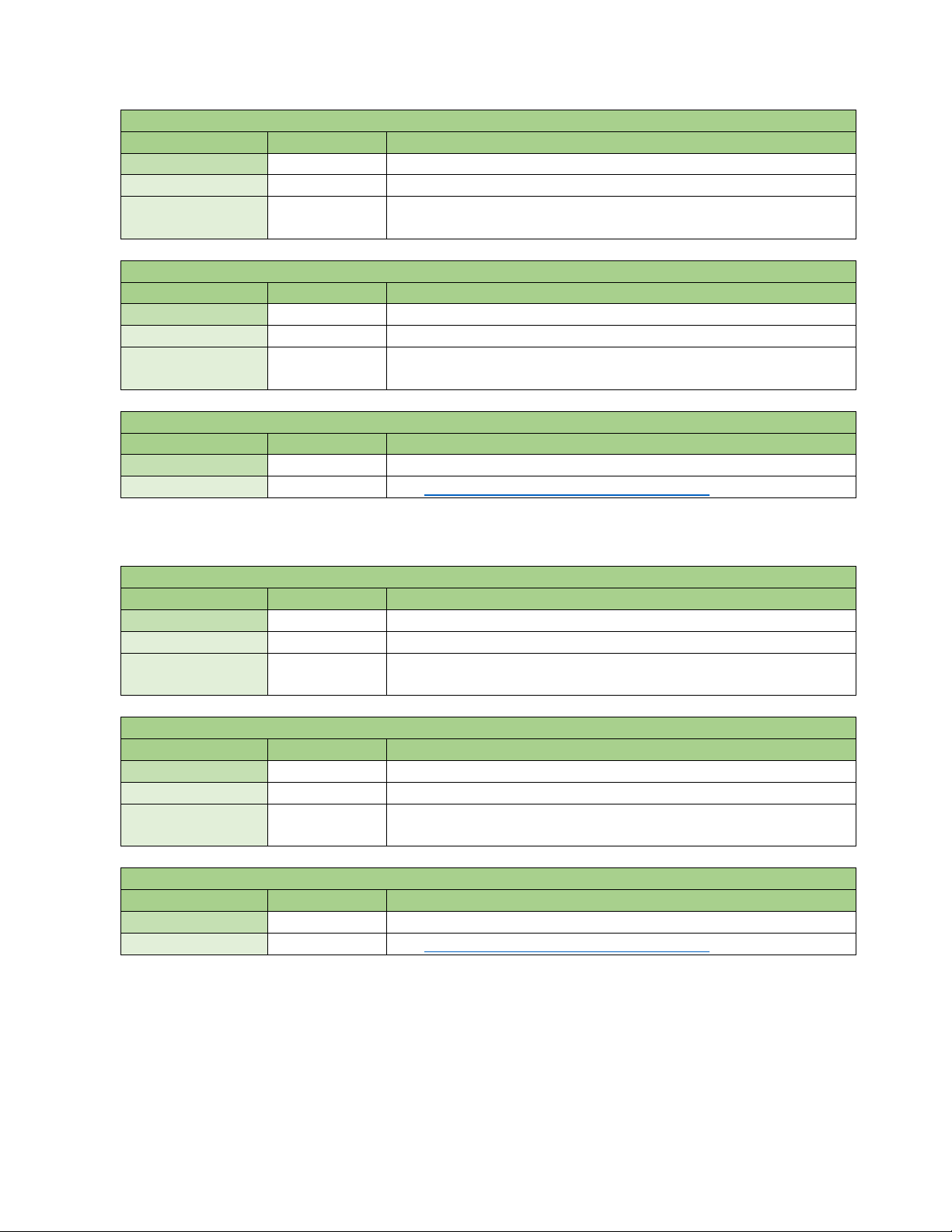
4.1.2 Protocol Data Unit
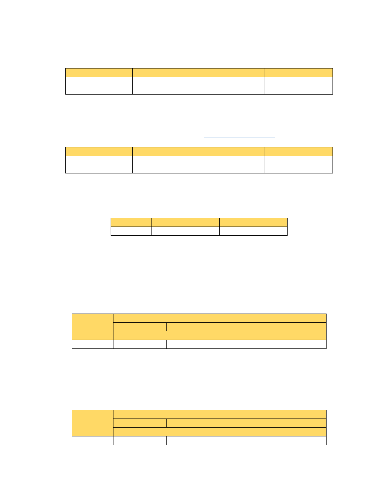
Protocol Data Unit (PDU)
Name
Size
Description
Function Code identifier.
Can be any of the hexadecimal codes listed in the Function Code table.
1 – 255
byte(s)
Payload for request/response transactions.
Varies depending on function code and number of addresses requested.
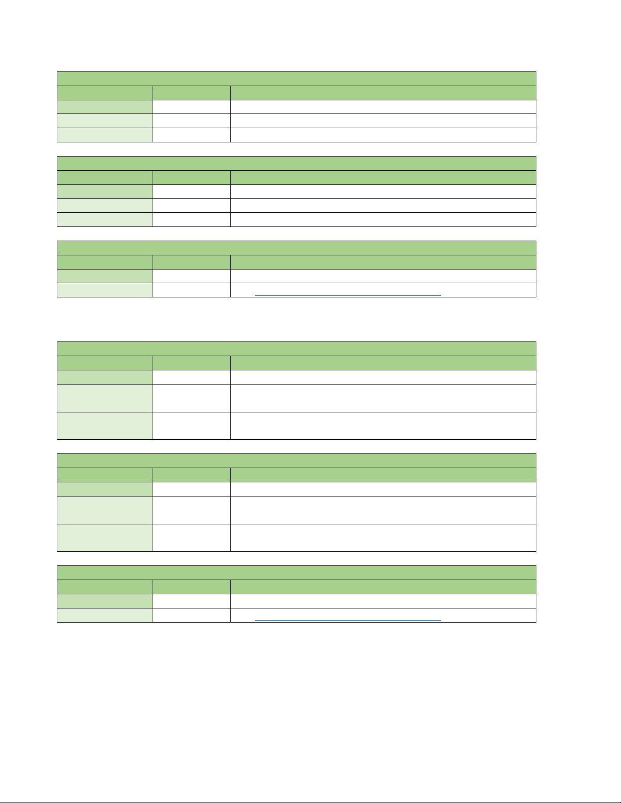
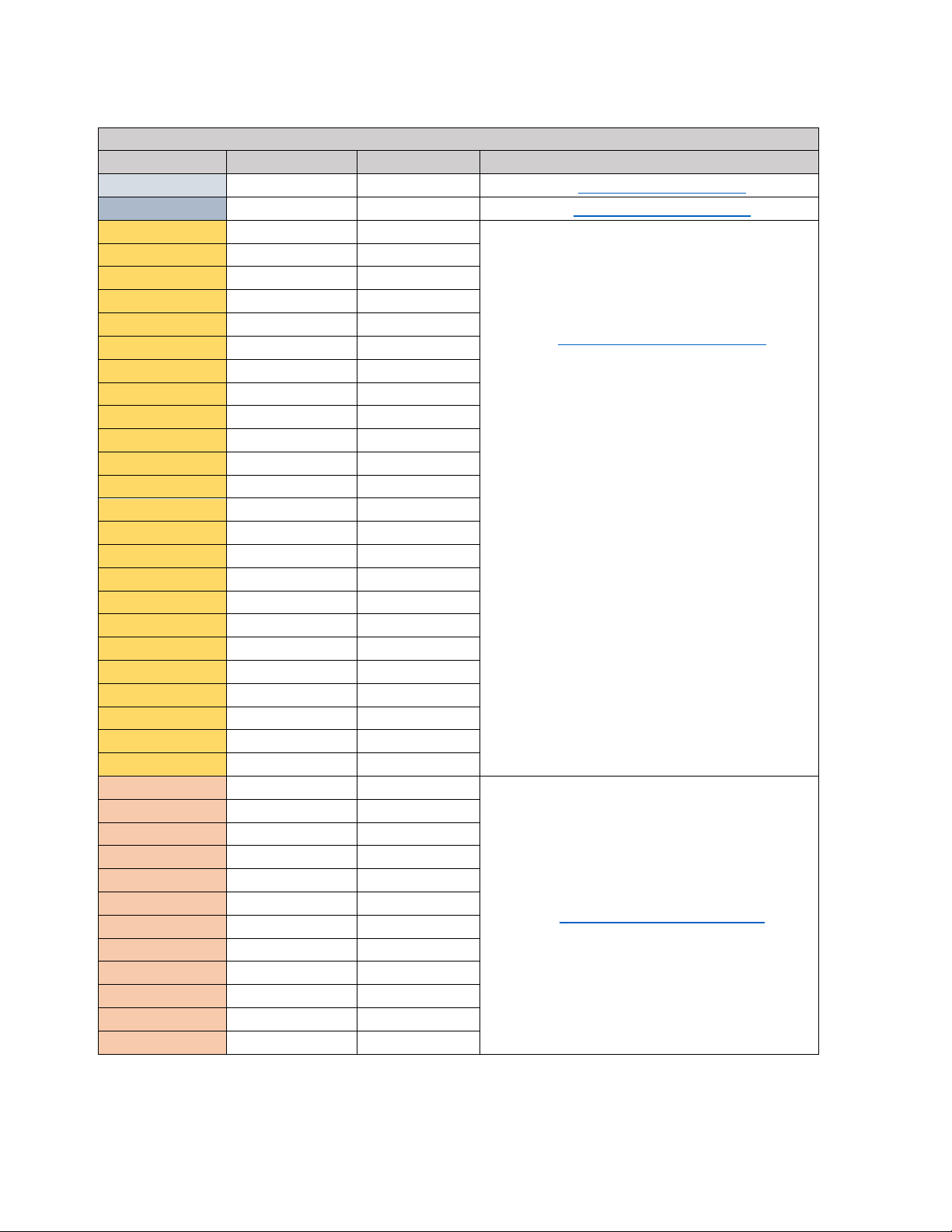
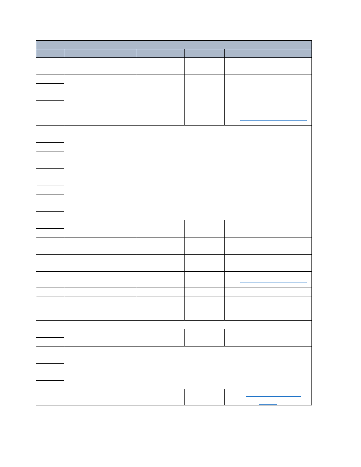
Supported Function Codes
Function
Code
Data Address
Range
FC1
(0x01)
Read up to 2000 consecutive 1-bit Coils within a single
request/response cycle.
FC2
(0x02)
Read Discrete
Inputs
Read up to 2000 consecutive 1-bit Discrete Inputs
within a single request/response cycle.
FC3
(0x03)
Read Holding
Registers
Read up to 125 consecutive 16-bit Holding Registers
within a single request/response cycle.
FC4
(0x04)
Read Input
Registers
Read up to 125 consecutive 16-bit Input Registers
within a single request/response cycle.
FC5
(0x05)
Write a single 1-bit Coil within a single
request/response cycle.
FC6
(0x06)
Write Single
Holding Register
Write a single 16-bit Holding Register within a single
request/response cycle.
FC16
(0x10)
Write Multiple
Holding Registers
Write up to 125 consecutive 16-bit Holding Registers
within a single request/response cycle.
The Protocol Data Unit (PDU) is made up of between 2 and 256 bytes, depending on the function and
number of data addresses requested:
Function Code 1 byte
Data Payload
4.1.3 Modbus/TCP Function Codes
The Modbus/TCP Server feature supports the following function codes:
Name Description
Read Coils
0xxxx
1xxxx
4xxxx
3xxxx
Write Single Coil
0xxxx
4xxxx
4xxxx
The consecutive address limitations of the Coils, Discrete Inputs, Holding Registers, and Input Registers
were established for the Modbus/TCP standard to maintain consistency with the original Modbus
protocol standard, even though a TCP/IP packet can contain a larger payload.
The Modbus/TCP feature allows for Function Codes 1 and 2 to be used interchangeably for read
requests. For example, a read coils (FC1) request for data addresses 00605 through 00610 will always
return the same result as a read discrete inputs (FC2) request for data addresses 10605 through 10610.
Likewise, the Modbus/TCP feature allows for Function Codes 3 and 4 to also be used interchangeably for
read requests. For example, a read holding registers (FC3) request for data addresses 40587 through
40590 will always return the same result as a read input registers (FC4) request for data addresses
30587 through 30590. All addresses accessible as a Coil or Discrete Input may also be accessed as a
Holding Register or Input Register.
Only the 4 least significant digits of the data address are explicitly stated in the Modbus message, with
the most significant (5
th
) digit being derived from the function code. However, generally the entire
5-digit data address must be specified in the Tag Database of an HMI.
3
Page 8
4.1.3.1 Function Code 1, Read Coils
Read Coils Request PDU
Name
Size
Description
Function Code
1 Byte
Function Code Identifier (0x01).
Starting Address
2 Bytes
The data address of the first Coil to read.
Quantity of Coils
2 Bytes
The number of Coils requested, maximum of 2000 per message.
Read Coils Response PDU
Name
Size
Description
Function Code
1 Byte
Function Code Identifier (0x01).
Byte Count
1 Byte
The number of data bytes to follow.
Coil Status
1-125 Bytes
8 Coils per byte, up to 2000 Coils per message.
Read Coils Exception PDU
Name
Size
Description
Error Code
1 Byte
0x80 plus Function Code Identifier (0x81).
Exception Code
1 Byte
See 4.1.4 Modbus/TCP Exception Error Codes
Read Discrete Inputs Request PDU
Name
Size
Description
Function Code
1 Byte
Function Code Identifier (0x02).
Starting Address
2 Bytes
The data address of the first Discrete Input to read.
Quantity of
Discrete Inputs
The number of Discrete Inputs requested, maximum of 2000 per
message.
Read Discrete Inputs Response PDU
Name
Size
Description
Function Code
1 Byte
Function Code Identifier (0x02).
Byte Count
1 Byte
The number of data bytes to follow.
Discrete Input
Status
8 Discrete Inputs per byte, up to 2000 Discrete Inputs per
message.
Read Discrete Inputs Exception PDU
Name
Size
Description
Error Code
1 Byte
0x80 plus Function Code Identifier (0x82).
Exception Code
1 Byte
See 4.1.4 Modbus/TCP Exception Error Codes
4.1.3.2 Function Code 2, Read Discrete Inputs
2 Bytes
1-125 Bytes
4
Page 9
4.1.3.3 Function Code 3, Read Holding Registers
Read Holding Registers Request PDU
Name
Size
Description
Function Code
1 Byte
Function Code Identifier (0x03).
Starting Address
2 Bytes
The data address of the first Holding Register to read.
Quantity of
Holding Registers
The total number of Holding Registers requested, maximum of
125 per message.
Read Holding Registers Response PDU
Name
Size
Description
Function Code
1 Byte
Function Code Identifier (0x03).
Byte Count
1 Byte
The number of data bytes to follow.
Holding Register
Values
1 Holding Register for every 2 bytes, maximum of 125 Holding
Registers per message.
Read Holding Registers Exception PDU
Name
Size
Description
Error Code
1 Byte
0x80 plus Function Code Identifier (0x83).
Exception Code
1 Byte
See 4.1.4 Modbus/TCP Exception Error Codes
Read Input Registers Request PDU
Name
Size
Description
Function Code
1 Byte
Function Code Identifier (0x04).
Starting Address
2 Bytes
The data address of the first Input Register to read.
Quantity of Input
Registers
The total number of Input Registers requested, maximum of 125
per message.
Read Input Registers Response PDU
Name
Size
Description
Function Code
1 Byte
Function Code Identifier (0x04).
Byte Count
1 Byte
The number of data bytes to follow.
Input Register
Values
1 Input Register for every 2 bytes, maximum of 125 Input
Registers per message.
Read Input Registers Exception PDU
Name
Size
Description
Error Code
1 Byte
0x80 plus Function Code Identifier (0x84).
Exception Code
1 Byte
See 4.1.4 Modbus/TCP Exception Error Codes
2 Bytes
2-250 Bytes
4.1.3.4 Function Code 4, Read Input Registers
2 Bytes
2-250 Bytes
5
Page 10
4.1.3.5 Function Code 5, Write Single Coil
Write Single Coil Request PDU
Name
Size
Description
Function Code
1 Byte
Function Code Identifier (0x05).
Coil Address
2 Bytes
The data address of the Coil to which to write.
Coil Value
2 Bytes
The value to write to the Coil (0xFF00 = On, 0x0000 = Off).
Write Single Coil Response PDU
Name
Size
Description
Function Code
1 Byte
Function Code Identifier (0x05).
Coil Address
2 Bytes
The data address of the Coil written.
Coil Value
2 Bytes
The value written to the Coil (0xFF00 = On, 0x0000 = Off).
Write Single Coil Exception PDU
Name
Size
Description
Error Code
1 Byte
0x80 plus Function Code Identifier (0x85).
Exception Code
1 Byte
See 4.1.4 Modbus/TCP Exception Error Codes
Write Single Holding Register Request PDU
Name
Size
Description
Function Code
1 Byte
Function Code Identifier (0x06).
Holding Register
Address
Holding Register
Value
Write Single Holding Register Response PDU
Name
Size
Description
Function Code
1 Byte
Function Code Identifier (0x06).
Holding Register
Address
Holding Register
Value
Write Single Holding Register Exception PDU
Name
Size
Description
Error Code
1 Byte
0x80 plus Function Code Identifier (0x86).
Exception Code
1 Byte
See 4.1.4 Modbus/TCP Exception Error Codes
4.1.3.6 Function Code 6, Write Single Holding Register
2 Bytes The data address of the Holding Register to which to write.
2 Bytes The value to write to the Holding Register.
2 Bytes The data address of the Holding Register written.
2 Bytes The value written to the Holding Register.
6
Page 11
4.1.3.7 Function Code 16, Write Multiple Holding Registers
Write Multiple Holding Registers Request PDU
Name
Size
Description
Function Code
1 Byte
Function Code Identifier (0x10).
Starting Address
2 Bytes
The data address of the first Holding Register to which to write.
Quantity of
Holding Registers
Byte Count
1 Byte
The number of data bytes to follow.
Holding Register
Values
2 bytes for every Holding Register, maximum of 125 Holding
Registers per message. Write Multiple Holding Registers Response PDU
Name
Size
Description
Function Code
1 Byte
Function Code Identifier (0x10).
Starting Address
2 Bytes
The data address of the Holding Register written.
Quantity of
Holding Registers
Write Multiple Holding Registers Exception PDU
Name
Size
Description
Error Code
1 Byte
0x80 plus Function Code Identifier (0x90).
Exception Code
1 Byte
See 4.1.4 Modbus/TCP Exception Error Codes
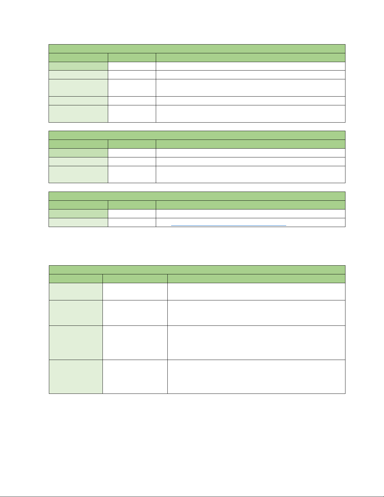
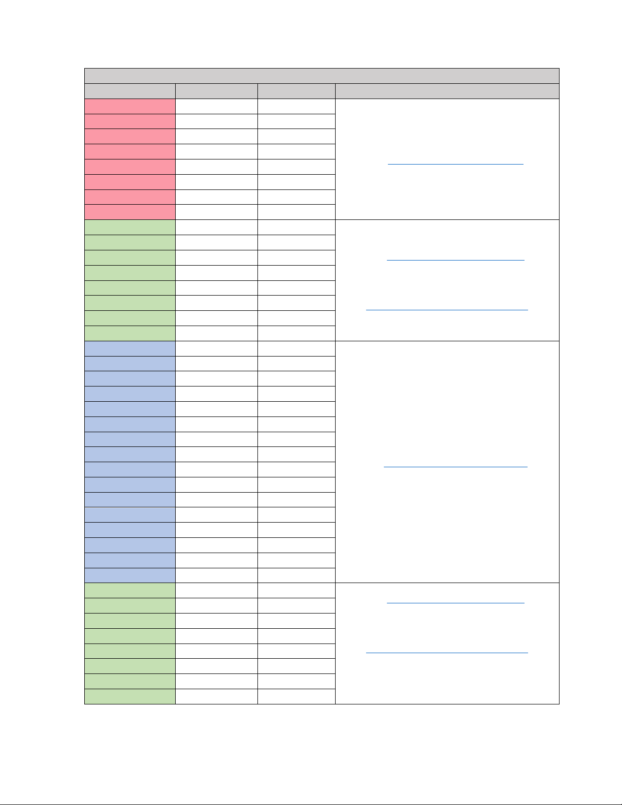
Supported Exception Codes
Exception Code
Name
Description
The function code received is not supported in the
controller.
The data address received is not an allowable address within
register requested is not valid for the function.
A value contained in the query data field for a Write
for the function.
An unrecoverable error occurred while the controller was
but the controller could provide a response.
2 Bytes Number of Holding Registers to write.
1-250 Bytes
2 Bytes Number of Holding Registers written.
4.1.4 Modbus/TCP Exception Error Codes
The Modbus/TCP feature supports the following Exception (Error) Codes:
0x01 Illegal Function
0x02 Illegal Data Address
0x03 Illegal Data Value
0x04 Slave Device Failure
When an exception occurs, the Response PDU contains a Function Code of 0x80 plus the original
hexadecimal Function Code.
the controller. This error will only be generated if the first
command is not an allowable value for field. This error will
only be generated if the first register requested is not valid
attempting to perform the requested action. This is a
general exception code indicating that the request was valid,
7
Page 12
4.2 TCP/IP Interface
Byte Value
Coil 1
Coil 2
6 unused bits
0x02
(00000010)
Word Value
Coil Value
Most Significant Byte
Least Significant Byte
0xFF00
(1111111100000000)
0xFF
(11111111)
0x00
(00000000)
Word Value
Bit Value
Most Significant Byte
Least Significant Byte
0x0001
(0000000000000001)
0x00
(00000000)
0x01
(00000001)
The Modbus/TCP interface is attached to the TCP/IP stack that is implemented within the Walchem
controller. When the Modbus feature is Enabled, the controller will listen to all communications that
come in on the Modbus/TCP registered port 502. This port can be changed in the Remote
Communications Menu.
4.3 Data Refresh
To ensure continued connectivity, the Modbus/TCP client should not request data more frequently than
once every 5000 msec. Faster refresh rates are unsupported and may result in unexpected behavior.
4.4 Data Encoding
Modbus uses a ‘big-endian’ representation for addresses and data items. This means that within each
register, when a numerical quantity larger than a single byte is transmitted, the MOST significant byte is
sent first. The following topics describe the different types of encoding and show how the data is
encoded within the Modbus/TCP packet. Most client drivers will extract the data from the packet in the
correct format for use/display within the client environment.
4.4.1 Coils and Discrete Inputs
4.4.1.1 Boolean
Coils and Discrete Inputs can be used for digital input states, relay states, alarm states, and reset buttons
that are representable as a 1 or a 0. All binary data is packed from least significant bit to most significant
bit into a byte containing up to 8 Coils or Discrete Inputs. Bits not containing the value of a Coil or
Discrete Input are space holders and have a value of 0.
0 1 000000
Reset buttons may also be packed as a 16-bit word when using the Write Single Coil function code.
(0xFF00 = On, 0x0000 = Off)
1
4.4.2 Holding Register and Input Registers
4.4.2.1 16-Bit Word (Boolean)
Holding Registers and Input Registers can be used for digital input states, relay states, alarm states, and
reset buttons that are representable as a 1 or a 0. All binary data can be packed into a 16-Bit register,
with the least significant bit of the least significant byte being occupied by the 1-bit value. This is
functionally identical to a 16-bit integer.
1
8
Page 13
4.4.2.2 16-Bit Word (Bitfield)
Word Value
Alarm Bitfield Value
Most Significant Byte
Least Significant Byte
0x00AA
(0000000010101010)
0x00
(00000000)
0xAA
(10101010)
Word Value
Alarm Bitfield Value
Most Significant Byte
Least Significant Byte
0x00AA
(0000000010101010)
0x00
(00000000)
0xAA
(10101010)
Word Value
Most Significant Byte
Least Significant Byte
0x1234
0x12
0x34
Register 1
Register 2
Most Significant
Least Significant
Most Significant
Least Significant
Least Significant Word
Most Significant Word
0x12345678
0x56
0x78
0x12
0x34
Register 1
Register 2
Most Significant
Least Significant
Most Significant
Least Significant
Least Significant Word
Most Significant Word
0x12345678
0x56
0x78
0x12
0x34
Holding Registers and Input Registers can be used for Alarm Bitfields. An 8-Bit Alarm bitfield is packed
into the least significant byte of a 16-bit register. This is offered as a single-register alternative to
accessing alarm states individually. Bitfields can be decoded in section 5.5 Alarm Bitfields
0xAA
.
4.4.2.3 16-Bit Word (Status)
Holding Registers and Input Registers can be used for enumerated values such as status codes. An 8-Bit
status code is packed into the least significant byte of a 16-bit register. This is functionally identical to
the 16-bit integer. Status codes are defined in section 5.4 Status Register Codes
0xAA
.
4.4.2.4 16-Bit Word (Integer)
Holding Registers and Input Registers can be used for 16-bit integers containing HOA settings, and time
data that don’t require 32-bit integers. All 16-bit integers are unsigned.
4.4.2.5 32-Bit Value (Integer)
Holding Registers and Input Registers can be used for 32-bit integer data containing elapsed time values
and timestamps. The system clock register and all registers containing timestamps use the Unix Time
format, that counts the seconds passed since 12:00:00 am, January 1
wide; therefore, a request message must include 2 consecutive registers to read or write a 32-bit
integer. The 32-bit value is transmitted with the least significant word first, then the most significant
word. All 32-bit integers are unsigned.
Word Value
st
, 1970. Registers are only 16 bits
4.4.2.6 32-Bit Value (Float)
Holding Registers and Input Registers can be used for 32-bit floating point data containing set points,
sensor readings, percentages, deadbands, etc. Registers are only 16 bits wide; therefore, a request
message must include 2 consecutive registers to read or write a 32-bit float. The 32-bit value is
transmitted with the least significant word first, then the most significant word.
Word Value
9
Page 14

4.4.2.7 32-Bit Inverse Data Format (Integer or Float)
Register 1
Register 2
Most Significant
Least Significant
Most Significant
Least Significant
Most Significant Word
Least Significant Word
0x12345678
0x12
0x34
0x56
0x78
32-bit integers and floats can use an inverse data format, where the contents of registers 1 and 2 are
switched. When inverse data format is selected, the 32-bit value is transmitted with the most significant
word first, then the least significant word. The data format setting can be modified in the Remote
Communications Settings Menu.
Word Value
5.0 DATA DICTIONARY
5.1 Addressing (0- or 1-Based)
The addressing within the Modbus/TCP protocol (that is, the data within the physical packet) is 0-based,
meaning the first element/item to be accessed is referenced by address 0. The Modbus standard for
handling and displaying data is 1-based, meaning the first element/data item to be accessed is
referenced by address 1.
For most client applications, users enter the 1-based number which is converted to 0-based addressing
at the protocol level. The addresses defined in the following address maps below are 1-based, as most
of the client applications work with this method. Register addresses for individual elements are derived
by adding the address offset in the appropriate Type-Specific Address Map
I/O Channel Address Map below.
to the starting address in the
5.2 Address Maps
The address map is a function code-agnostic map that contains all data values that can be accessed as
Coils (0xxxx), Discrete Inputs (1xxxx), Holding Registers (4xxxx), and Input Registers (3xxxx).
The Address Map of the Modbus/TCP feature is modular; valid addresses are determined by the add-on
card configuration of the controller and the task being performed by each Input or Output. Each object
has a block of 36 addresses.
The Modbus/TCP feature allows all addresses to be accessed as registers. On the following address map
tables, values in BOLD can also be accessed as a Coil or Discrete Input.
As examples, to read the ‘Controller Firmware Version’ from the System Address Map
x0037) as an Input Register (FC4), the address indices 2 and 3 must be requested together: Addresses
30039 and 30040.
To read the ‘Low Alarm’ status for Sensor 2-1 in a W600 Controller as a Coil (FC1), the
Address Map indicates the starting address is x0865. Address index 28 must be requested: Address
00893. For the W900 Controller, the ‘Low Alarm’ status for Sensor 2-1 is x1729 + 28 = Address 01757.
To write the ‘Setpoint’ for Relay 3 (set to On/Off control mode) in the
Address Map (staring address x9001) as a Holding Register (FC6), the address indices 6 and 7 must be
used together: Addresses 49007 and 49008.
Relay On/Off Control Mode
(starting address
Sensor Input
10
Page 15

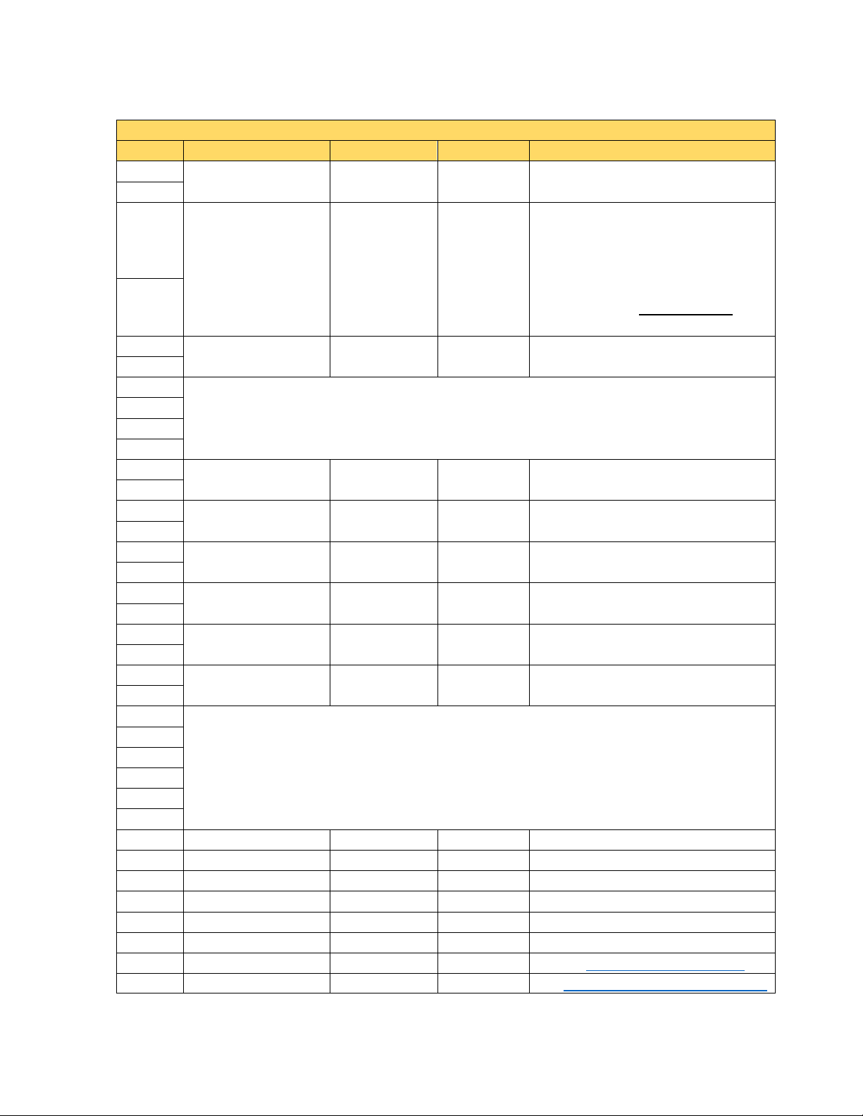
5.2.1 W600 Controller – I/O Channel Address Maps
W600 Controller – I/O Channel Address Map
Starting
Address
Ending
Address
Type-Specific Address Maps
System
Network
Sensor Input 1-1
Sensor Input 1-2
Sensor Input 1-3
Sensor Input 2-1
x0865
x0900
Sensor Input 2-2
x0901
x0936
Sensor Input 2-3
x0937
x0972
Digital Input 1
x0289
x0324
Digital Input 2
Digital Input 3
Digital Input 4
Digital Input 5
Digital Input 6
Virtual Input 1
Virtual Input 2
x5797
x5832
Relay Output 1
x8929
x8964
Relay Output 2
x8965
x9000
Relay Output 3
Relay Output 4
Relay Output 5
Relay Output 6
Analog Output 1
Analog Output 2
The address ranges for each input/output channel in the W600 controller are as follows:
Object
x0037 x0072 See 5.3.1 System Address Map
x0145 x0180 See 5.3.2 Network Address Map
x0577 x0612
x0613 x0648
x0649 x0684
x0325 x0360
x0361 x0396
x0397 x0432
x0433 x0468
x0469 x0504
x5761 x5796
See 5.3.3 Sensor Input Address Maps
See 5.3.4 Digital Input Address Maps
See 5.3.5 Virtual Input Address Maps
See 5.3.6 Relay Output Address Maps
x9001 x9036
x9037 x9072
x9073 x9108
x9109 x9144
x1153 x1188
x1189 x1224
5.3.7 Pulse Relay Output Address Maps
See 5.3.8 Analog Output Address Maps
Or
11
Page 16
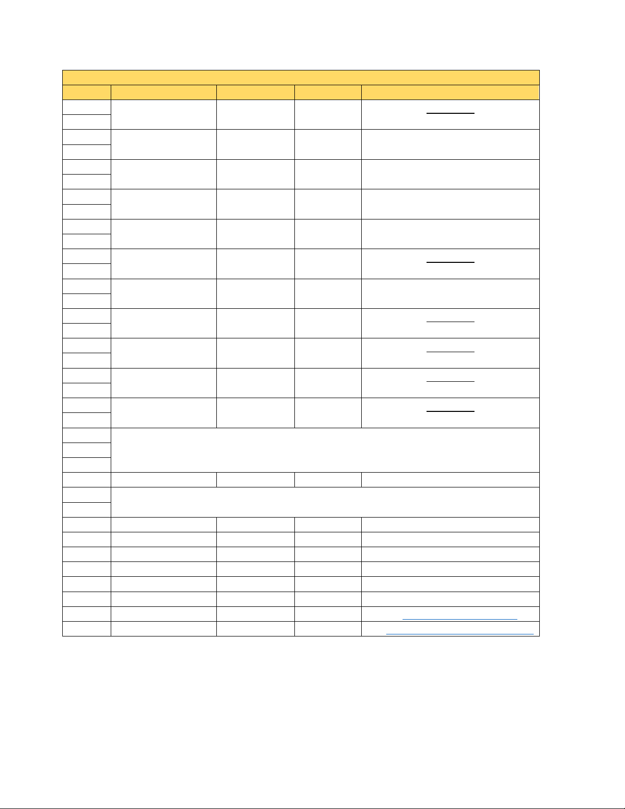
5.2.2 W900 Controller – I/O Channel Address Maps
W900 Controller – I/O Channel Address Map
Type-Specific Address Maps
System
Network
Sensor Input 1-1
Sensor Input 1-2
Sensor Input 1-3
Sensor Input 1-4
x1261
x1296
Sensor Input 1-5
x1297
x1332
Sensor Input 1-6
x1333
x1368
Sensor Input 2-1
Sensor Input 2-2
Sensor Input 2-3
Sensor Input 2-4
Sensor Input 2-5
Sensor Input 2-6
Sensor Input 3-1
Sensor Input 3-2
Sensor Input 3-3
x2377
x2412
Sensor Input 3-4
x2413
x2448
Sensor Input 3-5
x2449
x2484
Sensor Input 3-6
Sensor Input 4-1
Sensor Input 4-2
Sensor Input 4-3
Sensor Input 4-4
Sensor Input 4-5
Sensor Input 4-6
x3061
x3096
Digital Input 1
x0577
x0612
Digital Input 2
x0613
x0648
Digital Input 3
x0649
x0684
Digital Input 4
Digital Input 5
Digital Input 6
Digital Input 7
Digital Input 8
Digital Input 9
Digital Input 10
x0901
x0936
Digital Input 11
x0937
x0972
Digital Input 12
x0973
x1008
The address ranges for each input/output channel in the W900 controller are as follows:
Object Starting Address Ending Address
x0037 x0072 See 5.3.1 System Address Map
x0145 x0180 See 5.3.2 Network Address Map
x1153 x1188
x1189 x1224
x1225 x1260
x1729 x1764
x1765 x1800
x1801 x1836
x1837 x1872
x1873 x1908
x1909 x1944
x2305 x2340
x2341 x2376
x2485 x2520
x2881 x2916
x2917 x2952
x2953 x2988
x2989 x3024
x3025 x3060
See 5.3.3 Sensor Input Address Maps
Note: When using P/N 191918 I/O card with
2 Analog Input + 4 Analog Output channels,
the two (4-20 mA) Sensor Inputs are mapped
from channels 1 and 2 into channels 5 and 6.
For example, if the card is installed in the third
I/O slot, the register address mapping is:
Analog Output 3-1: x2305 to x2340
Analog Output 3-2: x2341 to x2376
Analog Output 3-3: x2377 to x2412
Analog Output 3-4: x2413 to x2448
Sensor Input 3-1: x2449 to x2484
Sensor Input 3-2: x2485 to x2520
x0685 x0720
x0721 x0756
x0757 x0792
x0793 x0828
x0829 x0864
x0865 x0900
12
See 5.3.4 Digital Input Address Maps
Page 17
W900 Controller – I/O Channel Address Map
Object
Starting Address
Ending Address
Type-Specific Address Maps
Virtual Input 1
x5761
x5796
Virtual Input 2
x5797
x5832
Virtual Input 3
Virtual Input 4
Virtual Input 5
Virtual Input 6
Virtual Input 7
Virtual Input 8
Relay Output 1
Relay Output 2
x8965
x9000
Relay Output 3
x9001
x9036
Relay Output 4
x9037
x9072
Relay Output 5
Relay Output 6
Relay Output 7
Relay Output 8
x9181
x9144
Analog Output 1-1
Analog Output 1-2
Analog Output 1-3
Analog Output 1-4
x1261
x1296
Analog Output 2-1
x1729
x1764
Analog Output 2-2
x1765
x1800
Analog Output 2-3
x1801
x1836
Analog Output 2-4
Analog Output 3-1
Analog Output 3-2
Analog Output 3-3
Analog Output 3-4
Analog Output 4-1
Analog Output 4-2
x2917
x2952
Analog Output 4-3
x2953
x2988
Analog Output 4-4
x2989
x3024
Control Output 1
Control Output 2
Control Output 3
Control Output 4
Control Output 5
Control Output 6
Control Output 7
x7129
x7164
Control Output 8
x7165
x7200
x5833 x5868
x5869 x5904
x5905 x5940
x5941 x5976
x5977 x6012
x6013 x6048
x8929 x8964
See 5.3.5 Virtual Input Address Maps
x9073 x9108
x9109 x9144
x9145 x9180
x1153 x1188
x1189 x1224
x1225 x1260
x1837 x1872
x2305 x2340
x2341 x2376
x2377 x2412
x2413 x2448
x2881 x2916
See 5.3.6 Relay Output Address Maps
Or
5.3.7 Pulse Relay Output Address Maps
See 5.3.8 Analog Output Address Maps
x6913 x6948
x6949 x6984
x6985 x7020
x7021 x7056
x7057 x7092
x7093 x7128
See 5.3.6 Relay Output Address Maps
Or
5.3.7 Pulse Relay Output Address Maps
Note: Control Outputs share address maps
and alarm bitfields with Relay control modes
13
Page 18
5.2.3 Alternate Address Maps
Primary Value; Status
Calibration Required
DI State; Interlock State
Low, High Alarms
Primary Value; Status
Alarm Bitfield
Relay State
Alarm Bitfield
Output Percent
Alarm Bitfield
Output State
Alarm Bitfield
Scenario #1: I/O Slot 2 Not Populated
Scenario #2: I/O Slot 2 Populated
Channel
Address
Alternate
Address
Channel
Address
Alternate
Address
I/O Slot 1: Dual Sensor Input Card
I/O Slot 1: Dual Sensor Input Card
Sensor Input 1-1
x1153
Sensor 1
x9217
Sensor Input 1-1
x1153
Sensor 1
x9217
Sensor Input 1-2
x1189
Sensor 2
x9219
Sensor Input 1-2
x1189
Sensor 2
x9219
Sensor Input 1-3
x1225
Sensor 3
x9221
Sensor Input 1-3
x1225
Sensor 3
x9221
Sensor Input 1-4
x1261
Sensor 4
x9223
Sensor Input 1-4
x1261
Sensor 4
x9223
I/O Slot 2: Not Populated
I/O Slot 2: Single Sensor Input Card
Sensor Input 2-1
x1729
Sensor 5
x9225
Sensor Input 2-2
x1765
Sensor 6
x9227
I/O Slot 3: Dual Analog Input Card
I/O Slot 3: Dual Analog Input Card
Sensor Input 3-1
x2305
Sensor 5
x9225
Sensor Input 3-1
x2305
Sensor 7
x9229
Sensor Input 3-2
x2341
Sensor 6
x9227
Sensor Input 3-2
x2341
Sensor 8
x9231
The I/O Address Maps in the previous sections are based on the hardware position/slot within the
controller. Alternate Address Maps use software-based, dynamic addressing to provide a more efficient
way to access similar data from different objects. Using these address tables, the same field type is
accessible using consecutive addresses. For example, the primary values for all sensors installed in the
controller can be accessed in a single Modbus FC4 request/response cycle starting at address 39217.
I/O Type Available Objects Type-Specific Alternate Address Map
Sensor Inputs
Digital Inputs
Virtual Inputs
Relay Outputs
Analog Outputs
Control Outputs
Alarm Bitfield
Low, High Alarms
LoLo, HiHi Alarms
Total Time
Flowrate;
Pulse Output Percent
Flow Total
Alarm Bitfield
Time On;
Time On; Status
Output Percent
Time On;
Status
Status
See 5.3.9.1 Alternate Sensor Input / Temperature Input /
Analog Input Address Map
See 5.3.9.2 Alternate Digital Input Address Map
See 5.3.9.3 Alternate Virtual Input Address Map
See 5.3.9.4 Alternate Relay Output Address Map
See 5.3.9.5 Alternate Analog Output Address Map
See 5.3.9.6 Alternate Control Output Address Map
Note that changing I/O card locations can affect the address used to access individual objects. For
example, if a W900 is configured with a Dual SI card in slot 1 and a Dual AI card in slot 3, the alternate
address mappings for the primary values are different if a Single SI card is inserted into slot 2:
14
Page 19

5.3 Type-Specific Address Maps
System Address Map
Address
Name
Data Encoding
Permissions
Value
0
1
2
Controller Firmware
Version
3
4
5
6
Controller Processor
Temperature
7
8
Network Card
Temperature
9
10
Digital Input Card
Temperature (W900 Only)
11
12
13
14
15
16
I/O Card 3 Temperature
(W900 Only)
17
18
I/O Card 4 Temperature
(W900 Only)
19
20
21
22
23
24
25
26
27
28
29
30
31
32
+12 V Supply
(W900 Only)
33
34
35
Alarm Bitfield
16-Bit Bitfield
Read
See 5.5.1 System Alarm Bitfield
5.3.1 System Address Map
Controller Time 32-Bit Integer Read Unix Time
32-Bit Float Read
Date of Last Data Log 32-Bit Integer Read Unix Time
32-Bit Float Read °C
32-Bit Float Read °C
32-Bit Float Read °C
I/O Card 1 Temperature 32-Bit Float Read °C
I/O Card 2 Temperature 32-Bit Float Read °C
32-Bit Float Read °C
32-Bit Float Read °C
Battery Power 32-Bit Float Read Volt
+3.3 V Supply 32-Bit Float Read Volt
+5 V Supply 32-Bit Float Read Volt
32-Bit Float Read Volt
15
Page 20
5.3.2 Network Address Map
Network Address Map
Address
Name
Data Encoding
Permissions
Value
0
1
2
VTouch Last
Configuration Time
3
4
5
VTouch LiveConnect
Status
7
8
9
10
11
12
13
14
15
16
17
18
19
20
21
22
WiFi Channel
(W900 Only)
23
WiFi Security
(W900 Only)
25
WiFi Status (W900 Only)
16-Bit Status
Read
See 5.4 Status Register Codes
Begin Temporary
(W900 Only)
27
28
29
30
31
32
33
34
See 5.5.2 Network Alarm
Bitfield
VTouch Last Data Time 32-Bit Integer Read Unix Time
VTouch Refresh Rate 32-Bit Float Read/Write 1 – 1440 Minutes
32-Bit Integer Read Unix Time
24
6
WiFi Signal Strength
(W900 Only)
WiFi RSSI
(W900 Only)
16-Bit Status Read See 5.4 Status Register Codes
32-Bit Float Read -30 – -100 dBm
32-Bit Float Read 0 – 100%
32-Bit Float Read 1 – 14
16-Bit Status Read See 5.4 Status Register Codes
26
Ad-Hoc Mode Session
Ad-Hoc Mode Time Limit
35 Alarm Bitfield 16-Bit Bitfield Read
(W900 Only)
Boolean Read/Write
32-Bit Float Read/Write
16
Write 1 to Begin Temporary
Ad-Hoc Mode Session
1 – 1440 minutes
Page 21
5.3.3 Sensor Input Address Maps
Sensor Input (all types except Analog Input Flowmeter) Address Map
Address
Name
Data Encoding
Permissions
Value
0
1
Cond: µS/cm before ATC
Temperature: Ω
Corrosion Rate: mpy (Mild Steel)
Imbalance
4
5
6
7
8
9
10
11
12
13
14
15
16
17
18
19
20
21
22
23
24
25
26
27
28
Low Alarm
Boolean
Read
1 = Alarm Active
29
High Alarm
Boolean
Read
1 = Alarm Active
30
LoLo Alarm
Boolean
Read
1 = Alarm Active
31
HiHi Alarm
Boolean
Read
1 = Alarm Active
32
Cal Required
Boolean
Read
1 = Alarm Active
33
Input Failure
Boolean
Read
1 = Alarm Active
34
Status
16-Bit Status
Read
See 5.4 Status Register Codes
35
Alarm Bitfield
16-Bit Bitfield
Read
See 5.5.3 Sensor Input Alarm Bitfield
5.3.3.1 Sensor Input (all types except Analog Input Flowmeter) Address Map
Primary Value 32-Bit Float Read Sensor Units
2
Active, Cu/Ni: mV
4-20 mA Input: mA
Primary Raw Value 32-Bit Float Read
3
Imbalance: Corrosion Rate
Last Calibration Date 32-Bit Integer Read Unix Time
Deadband 32-Bit Float Read/Write Sensor Units
Smoothing Factor 32-Bit Float Read/Write 0 – 90%
LoLo Alarm Setpoint 32-Bit Float Read/Write Sensor Units
Low Alarm Setpoint 32-Bit Float Read/Write Sensor Units
High Alarm Setpoint 32-Bit Float Read/Write Sensor Units
HiHi Alarm Setpoint 32-Bit Float Read/Write Sensor Units
17
Page 22
5.3.3.2 Analog Input Flowmeter Address Map
Analog Input Flowmeter Address Map (W900 Controller Only)
Address
Name
Data Encoding
Permissions
Value
0
Flow Units
Rate Units
1
2
3
4
5
6
7
8
9
10
Flow Units
Rate Units
11
12
13
14
15
16
17
18
Rate Units
19
20
Flow Units
Rate Units
21
22
23
24
25
Reset Total Flow
Boolean
Read/Write
Write 1 to Reset Flow Total
26
27
28
Low Alarm
Boolean
Read
1 = Alarm Active
29
High Alarm
Boolean
Read
1 = Alarm Active
30
LoLo Alarm
Boolean
Read
1 = Alarm Active
31
HiHi Alarm
Boolean
Read
1 = Alarm Active
32
Cal Required
Boolean
Read
1 = Alarm Active
33
Input Failure
Boolean
Read
1 = Alarm Active
34
Status
16-Bit Status
Read
See 5.4 Status Register Codes
35
Alarm Bitfield
16-Bit Bitfield
Read
See 5.5.3 Sensor Input Alarm Bitfield
Primary Value 32-Bit Float Read
Primary Raw Value 32-Bit Float Read mA
Last Calibration Date 32-Bit Integer Read Unix Time
Flow Total 32-Bit Float Read Flow Units
Input Filter 32-Bit Float Read/Write mA
Deadband 32-Bit Float Read/Write
Smoothing Factor 32-Bit Float Read/Write 0 – 90%
LoLo Alarm Setpoint 32-Bit Float Read/Write
Low Alarm Setpoint 32-Bit Float Read/Write
High Alarm Setpoint 32-Bit Float Read/Write
HiHi Alarm Setpoint 32-Bit Float Read/Write
Flow Units
Rate Units
Flow Units
Rate Units
Flow Units
18
Page 23

5.3.4 Digital Input Address Maps
Digital Input / DI State Type Address Map
Address
Name
Data Encoding
Permissions
Value
0
1
2
3
4
5
6
7
8
9
10
11
12
13
14
15
16
17
18
19
20
21
22
23
24
25
26
27
28
29
30
31
32
Reset Total Time
Boolean
Read/Write
Write 1 to Reset Time
33
DI State
Boolean
Read
0 = Open, 1 = Closed
0 = Inactive
1 = Active Interlock
See 5.5.4 Digital Input Alarm Bitfield
Returns 1 if any alarm is active
5.3.4.1 Digital Input / DI State Type Address Map
Last Reset Date 32-Bit Integer Read Unix Time
Total Time 32-Bit Integer Read Seconds
Cycle Time 32-Bit Integer Read Seconds
34 Interlock State Boolean Read
35 Alarm Bitfield 16-Bit Bitfield Read
When accessed as a Coil,
19
Page 24
5.3.4.2 Digital Input / Contacting Flow Meter Type Address Map
Digital Input / Contacting Flow Meter Address Map
Data
Encoding
0
1
2
3
4
5
6
7
8
9
10
11
12
13
14
15
16
17
18
19
20
21
22
23
24
25
26
27
28
29
30
31
32
Reset Total Flow
Boolean
Read/Write
Write 1 to Reset Flow Total
33
34
See 5.5.4 Digital Input Alarm Bitfield
Returns 1 if any alarm is active
Address Name
Last Reset Date 32-Bit Integer Read Unix Time
Total Flow 32-Bit Float Read Flow Units
Total Flow Alarm
Setpoint
Permissions Value
32-Bit Float Read/Write
0 – 1,000,000,000
Flow Units
35 Alarm Bitfield 16-Bit Bitfield Read
When accessed as a Coil,
20
Page 25

5.3.4.3 Digital Input / Paddlewheel Flow Meter Type Address Map
Digital Input / Paddlewheel Flow Meter Address Map
Data
Encoding
0
1
2
3
4
Flow Units
Rate Units
5
6
7
8
9
10
Rate Units
11
12
13
14
15
16
17
18
19
20
21
22
23
24
25
26
27
28
29
30
31
32
Reset Total Flow
Boolean
Read/Write
Write 1 to Reset Flow Total
33
34
See 5.5.4 Digital Input Alarm Bitfield
Returns 1 if any alarm is active
Address Name
Last Reset Date 32-Bit Integer Read Unix Time
Total Flow 32-Bit Float Read Flow Units
Current Flowrate 32-Bit Float Read
Total Flow Alarm
Setpoint
Deadband 32-Bit Float Read/Write
Smoothing Factor 32-Bit Float Read/Write 0 – 90%
Low Alarm Setpoint 32-Bit Float Read/Write
High Alarm Setpoint 32-Bit Float Read/Write
Permissions Value
32-Bit Float Read/Write
0 – 1,000,000,000
Flow Units
Flow Units
Flow Units
Rate Units
Flow Units
Rate Units
35 Alarm Bitfield 16-Bit Bitfield Read
When accessed as a Coil,
21
Page 26

5.3.4.4 Digital Input / DI Counter Type Address Map
Digital Input / DI Counter Address Map (W900 Controller Only)
Data
Encoding
0
1
2
3
4
Units
Rate Units
5
6
7
8
9
10
11
12
13
14
15
16
17
18
19
20
21
22
23
24
25
26
27
28
29
30
31
32
Reset Total
Boolean
Read/Write
Write 1 to Reset Total
33
34
See 5.5.4 Digital Input Alarm Bitfield
Returns 1 if any alarm is active
Address Name
Last Reset Date 32-Bit Integer Read Unix Time
Total Count 32-Bit Float Read Units
Current Rate 32-Bit Float Read
Total Alarm
Setpoint
Smoothing Factor 32-Bit Float Read/Write 0 – 90%
Permissions Value
32-Bit Float Read/Write
0 – 1,000,000,000
Units
35 Alarm Bitfield 16-Bit Bitfield Read
When accessed as a Coil,
22
Page 27

5.3.4.5 Digital Input / Flow Monitor Type Address Map
Digital Input / Flow Monitor Address Map
Addres
s
0
1
2
3
4
Flow Units
Rate Units
5
6
7
8
9
10
11
12
13
14
Reprime Time
16-Bit Integer
Read/Write
0 – 3599 Seconds
15
Flow Alarm Delay
16-Bit Integer
Read/Write
10 – 3599 Seconds
16
17
18
19
20
21
22
23
24
25
26
27
28
29
30
31
32
Reset Total Flow
Boolean
Read/Write
Write 1 to Reset Flow Total
33
34
See 5.5.4 Digital Input Alarm Bitfield
Returns 1 if any alarm is active
Name Data Encoding Permissions Value
Last Reset Date 32-Bit Integer Read Unix Time
Total Feed 32-Bit Float Read Flow Units
Current Flowrate 32-Bit Float Read
Totalizer Alarm
Setpoint
32-Bit Float Read/Write
Volume/Contact 32-Bit Float Read/Write
0 – 1,000,000
Flow Units
0.001 – 1000.000
Flow Units / Pulse
Smoothing Factor 32-Bit Float Read/Write 0 – 90%
Flow Alarm Clear 32-Bit Float Read/Write 1 – 100,000 Pulses
35 Alarm Bitfield 16-Bit Bitfield Read
When accessed as a Coil,
23
Page 28

5.3.5 Virtual Input Address Maps
Virtual Input / Calculation & Raw Value Type Address Map
Address
Name
Data Encoding
Permissions
Value
0
1
2
3
4
5 6
7
8
9
10
11
12
13
14
15
16
17
18
19
20
21
22
23
24
25
26
27
28
Low Alarm
Boolean
Read
1 = Alarm Active
29
High Alarm
Boolean
Read
1 = Alarm Active
30
LoLo Alarm
Boolean
Read
1 = Alarm Active
31
HiHi Alarm
Boolean
Read
1 = Alarm Active
32
1 = Out-Of-Range or
Input Failure Alarm Active
34
Status
16-Bit Status
Read
See 5.4 Status Register Codes
See 5.5.5 Virtual Input Alarm
Bitfield
5.3.5.1 Virtual Input / Calculation & Raw Value Type Address Map
Primary Value 32-Bit Float Read Virtual Input Units
Deadband 32-Bit Float Read/Write Virtual Input Units
Smoothing Factor 32-Bit Float Read/Write 0 – 90%
LoLo Alarm Setpoint 32-Bit Float Read/Write Virtual Input Units
Low Alarm Setpoint 32-Bit Float Read/Write Virtual Input Units
High Alarm Setpoint 32-Bit Float Read/Write Virtual Input Units
HiHi Alarm Setpoint 32-Bit Float Read/Write Virtual Input Units
33 Misc. Alarm Boolean Read
35 Alarm Bitfield 16-Bit Bitfield Read
24
Page 29

5.3.5.2 Virtual Input / Redundant Sensor Type Address Map
Virtual Input / Redundant Sensor Type Address Map (W900 Controller Only)
Address
Name
Data Encoding
Permissions
Value
0
1
2
3
4
5 6
7
8
9
10
11
12
13
14
15
16
17
18
19
20
21
22
23
24
25
26
27
28
29
30
31
32
Deviation Alarm
Boolean
Read
1 = Alarm Active
33
Misc. Alarm
Boolean
Read
1 = Input Failure Alarm Active
34
Status
16-Bit Status
Read
See 5.4 Status Register Codes
See 5.5.5 Virtual Input Alarm
Bitfield
Primary Value 32-Bit Float Read Virtual Input Units
Deadband 32-Bit Float Read/Write Virtual Input Units
Deviation Alarm
Setpoint
35 Alarm Bitfield 16-Bit Bitfield Read
32-Bit Float Read/Write Virtual Input Units
25
Page 30

5.3.5.3 Virtual Input / Disturbance Type Address Map
Virtual Input / Disturbance Type Address Map (W900 Controller Only)
Address
Name
Data Encoding
Permissions
Value
0
1
2
3
4
5
6
7
8
9
10
11
12
13
14
15
16
17
18
19
20
21
22
23
24
25
26
27
28
29
30
31
32
33
34
Status
16-Bit Status
Read
See 5.4 Status Register Codes
See 5.5.5 Virtual Input Alarm
Bitfield
Primary Value 32-Bit Float Read Unitless
Minimum Value 32-Bit Float Read/Write Unitless
Maximum Value 32-Bit Float Read/Write Unitless
Smoothing Factor 32-Bit Float Read/Write 0 – 90%
Disturbance Setpoint 32-Bit Float Read/Write Disturbance Input Units
Max Disturbance 32-Bit Float Read/Write Disturbance Input Units
35 Alarm Bitfield 16-Bit Bitfield Read
26
Page 31

5.3.6 Relay Output Address Maps
Relay Output / Manual Control Address Map
Address
Name
Data Encoding
Permissions
Value
0
1
2
3
4
5
6
7
8
9
10
11
12
13
14
15
16
17
18
19
20
21
22
23
24
25
26
27
28
29
30
31
Relay State
Boolean
Read
0 = Off, 1 = On
32
Reset Time Total
Boolean
Read/Write
Write 1 to Reset Time Total
0 = Hand, 1 = Off,
2 = Auto Mode
34
Status
16-Bit Status
Read
See 5.4 Status Register Codes
See 5.5.6 Relay Output Alarm Bitfield
Returns 1 if any alarm is active
5.3.6.1 Relay Output / Manual Control Mode Address Map
Time On 32-Bit Integer Read Seconds
Total Time 32-Bit Integer Read Seconds
On Time Delay 32-Bit Integer Read/Write 0 – 86,399 Seconds
Off Time Delay 32-Bit Integer Read/Write 0 – 86,399 Seconds
Hand Time Limit 32-Bit Integer Read/Write 0 – 86,399 Seconds
33 HOA Setting 16-Bit Integer Read/Write
35 Alarm Bitfield 16-Bit Bitfield Read
When accessed as a Coil,
27
Page 32

5.3.6.2 Relay Output / On/Off & On/Off Disturbance Control Mode Address Map
Relay Output / On/Off & On/Off Disturbance Control Address Map
Data
Encoding
0
1
2
3
4
5
6
7
8
9
10
11
12
13
14
Duty Cycle Period
16-Bit Integer
Read/Write
0 – 3599 Seconds
15
16
17
18
19
20
21
22
23
24
25
26
27
28
29
30
Reset Output Timeout
Boolean
Read/Write
Write 1 to Reset Output Timeout
31
Relay State
Boolean
Read
0 = Off, 1 = On
32
Reset Time Total
Boolean
Read/Write
Write 1 to Reset Time Total
0 = Hand, 1 = Off,
2 = Auto Mode
34
Status
16-Bit Status
Read
See 5.4 Status Register Codes
See 5.5.6 Relay Output Alarm Bitfield
Returns 1 if any alarm is active
Address Name
Time On 32-Bit Integer Read Seconds
Total Time 32-Bit Integer Read Seconds
Setpoint 32-Bit Float Read/Write Input Sensor Units
Deadband 32-Bit Float Read/Write Input Sensor Units
Duty Cycle 32-Bit Float Read/Write 0 – 100%
Permissions Value
On Time Delay 32-Bit Integer Read/Write 0 – 86,399 Seconds
Off Time Delay 32-Bit Integer Read/Write 0 – 86,399 Seconds
Output Time Limit 32-Bit Integer Read/Write 0 – 86,399 Seconds
Hand Time Limit 32-Bit Integer Read/Write 0 – 86,399 Seconds
33 HOA Setting 16-Bit Integer Read/Write
35 Alarm Bitfield 16-Bit Bitfield Read
When accessed as a Coil,
28
Page 33

5.3.6.3 Relay Output / Dual Setpoint Control Mode Address Map
Relay Output / Dual Setpoint Control Address Map
Data
Encoding
0
1
2
3
4
5
6
7
8
9
10
11
12
13
14
Duty Cycle Period
16-Bit Integer
Read/Write
0 – 3599 Seconds
15
16
17
18
19
20
21
22
23
24
25
26
27
28
29
30
Reset Output Timeout
Boolean
Read/Write
Write 1 to Reset Output Timeout
31
Relay State
Boolean
Read
0 = Off, 1 = On
32
Reset Time Total
Boolean
Read/Write
Write 1 to Reset Time Total
0 = Hand, 1 = Off,
2 = Auto Mode
34
Status
16-Bit Status
Read
See 5.4 Status Register Codes
See 5.5.6 Relay Output Alarm Bitfield
Returns 1 if any alarm is active
Address Name
Time On 32-Bit Integer Read Seconds
Total Time 32-Bit Integer Read Seconds
Setpoint 1 32-Bit Float Read/Write Input Sensor Units
Setpoint 2 32-Bit Float Read/Write Input Sensor Units
Deadband 32-Bit Float Read/Write Input Sensor Units
Duty Cycle 32-Bit Float Read/Write 0 – 100%
Permissions Value
On Time Delay 32-Bit Integer Read/Write 0 – 86,399 Seconds
Off Time Delay 32-Bit Integer Read/Write 0 – 86,399 Seconds
Output Time Limit 32-Bit Integer Read/Write 0 – 86,399 Seconds
Hand Time Limit 32-Bit Integer Read/Write 0 – 86,399 Seconds
33 HOA Setting 16-Bit Integer Read/Write
35 Alarm Bitfield 16-Bit Bitfield Read
When accessed as a Coil,
29
Page 34

5.3.6.4 Relay Output / Time Proportional Control Mode Address Map
Relay Output / Time Proportional Control Address Map
Data
Encoding
0
1
2
32-Bit
Integer
3
4
32-Bit
Integer
5
6
7
8
9
10
11
12
13
14
32-Bit
Integer
15
16
17
18
19
20
21
22
32-Bit
Integer
23
24
25
26
27
28
29
Reset Output
Timeout
31
Relay State
Boolean
Read
0 = Off, 1 = On
32
Reset Time Total
Boolean
Read/Write
Write 1 to Reset Time Total
16-Bit
Integer
0 = Hand, 1 = Off,
2 = Auto Mode
16-Bit
Status
See 5.5.6 Relay Output Alarm Bitfield
Returns 1 if any alarm is active
Address Name
Time On
Total Time
Cycle Time
Setpoint 32-Bit Float Read/Write Input Sensor Units
Proportional Band 32-Bit Float Read/Write Input Sensor Units
Current Cycle 32-Bit Float Read Seconds
Sample Period
32-Bit
Integer
Permissions Value
Read Seconds
Read Seconds
Read Seconds
Read/Write 10 – 86,399 Seconds
Output Time Limit
Hand Time Limit
30
33 HOA Setting
34 Status
35 Alarm Bitfield
Read/Write 0 – 86,399 Seconds
32-Bit
Integer
Read/Write 0 – 86,399 Seconds
Boolean Read/Write Write 1 to Reset Output Timeout
Read/Write
Read See 5.4 Status Register Codes
16-Bit
Bitfield
Read
When accessed as a Coil,
30
Page 35

5.3.6.5 Relay Output / Intermittent Sampling Control Mode Address Map
Relay Output / Intermittent Sampling Control Address Map
Data
Encoding
0
1
2
3
4
5
6
7
8
9
10
11
12
13
14
Sample Time
16-Bit Integer
Read/Write
10 – 3599 Seconds
15
Hold Time
16-Bit Integer
Read/Write
10 – 3599 Seconds
16
17
18
19
20
21
22
23
24
25
26
27
28
29
30
Reset Output Timeout
Boolean
Read/Write
Write 1 to Reset Output Timeout
31
Relay State
Boolean
Read
0 = Off, 1 = On
32
Reset Time Total
Boolean
Read/Write
Write 1 to Reset Time Total
0 = Hand, 1 = Off,
2 = Auto Mode
34
Status
16-Bit Status
Read
See 5.4 Status Register Codes
See 5.5.6 Relay Output Alarm Bitfield
Returns 1 if any alarm is active
Address Name
Time On 32-Bit Integer Read Seconds
Total Time 32-Bit Integer Read Seconds
Cycle Time 32-Bit Integer Read Seconds
Setpoint 32-Bit Float Read/Write Input Sensor Units
Proportional Band 32-Bit Float Read/Write Input Sensor Units
Max Blowdown 32-Bit Integer Read/Write 0 – 86,399 Seconds
Permissions Value
Wait Time 32-Bit Integer Read/Write 0 – 86,399 Seconds
Output Time Limit 32-Bit Integer Read/Write 0 – 86,399 Seconds
Hand Time Limit 32-Bit Integer Read/Write 0 – 86,399 Seconds
33 HOA Setting 16-Bit Integer Read/Write
35 Alarm Bitfield 16-Bit Bitfield Read
When accessed as a Coil,
31
Page 36

5.3.6.6 Relay Output / Bleed And Feed Control Mode Address Map
Relay Output / Bleed And Feed Control Address Map
Data
Encoding
0
1
2
3
4
5
6 7
8
9 10
11
12 13
14
15 16
17
18 19
20
21 22
23
24 25
26
27 28
29
30
Reset Output Timeout
Boolean
Read/Write
Write 1 to Reset Output Timeout
31
Relay State
Boolean
Read
0 = Off, 1 = On
32
Reset Time Total
Boolean
Read/Write
Write 1 to Reset Time Total
0 = Hand, 1 = Off,
2 = Auto Mode
34
Status
16-Bit Status
Read
See 5.4 Status Register Codes
See 5.5.6 Relay Output Alarm Bitfield
Returns 1 if any alarm is active
Address Name
Time On 32-Bit Integer Read Seconds
Total Time 32-Bit Integer Read Seconds
Permissions Value
Feed Time Limit 32-Bit Integer Read/Write 0 – 86,399 Seconds
Hand Time Limit 32-Bit Integer Read/Write 0 – 86,399 Seconds
33 HOA Setting 16-Bit Integer Read/Write
35 Alarm Bitfield 16-Bit Bitfield Read
When accessed as a Coil,
32
Page 37

5.3.6.7 Relay Output / Bleed Then Feed Control Mode Address Map
Relay Output / Bleed Then Feed Control Mode Address Map
Data
Encoding
0
1
2
3
4
5
6
7
8 9 10 11 12 13 14 15 16 17 18 19 20
21
22
23
24 25 26 27
Reset Timer
Boolean
Read/Write
Write 1 to Reset Feed Timer
28
29
30
Reset Output Timeout
Boolean
Read/Write
Write 1 to Reset Output Timeout
31
Relay State
Boolean
Read
0 = Off, 1 = On
32
Reset Time Total
Boolean
Read/Write
Write 1 to Reset Time Total
0 = Hand, 1 = Off,
2 = Auto Mode
34
Status
16-Bit Integer
Read
See 5.4 Status Register Codes
See 5.5.6 Relay Output Alarm Bitfield
Returns 1 if any alarm is active
Address Name
Time On 32-Bit Integer Read Seconds
Total Time 32-Bit Integer Read Seconds
Remaining Feed Time 32-Bit Integer Read Seconds
Bleed Time 32-Bit Integer Read Seconds
Permissions Value
Feed Percentage 32-Bit Float Read/Write 0 – 100%
Feed Time Limit 32-Bit Integer Read/Write 0 – 86,399 Seconds
Hand Time Limit 32-Bit Integer Read/Write 0 – 86,399 Seconds
33 HOA Setting 16-Bit Integer Read/Write
35 Alarm Bitfield 16-Bit Bitfield Read
When accessed as a Coil,
33
Page 38

5.3.6.8 Relay Output / Flow Timer Control Mode Address Map
Relay Output / Flow Timer Control Mode Address Map
Data
Encoding
0
1
2
32-Bit
Integer
3
4
32-Bit
Integer
5
6
7
8
9
10
11
12
13
14
15
16
17
18
19
20
21
22
32-Bit
Integer
23
24
25
26
27
Reset Timer
Boolean
Read/Write
Write 1 to Reset Feed Timer
28
29
30
Reset Output Timeout
Boolean
Read/Write
Write 1 to Reset Output Timeout
31
Relay State
Boolean
Read
0 = Off, 1 = On
32
Reset Time Total
Boolean
Read/Write
Write 1 to Reset Time Total
16-Bit
Integer
0 = Hand, 1 = Off,
2 = Auto Mode
16-Bit
Integer
See 5.5.6 Relay Output Alarm Bitfield
Returns 1 if any alarm is active
Address Name
Time On
Total Time
Remaining Feed Time
Accumulator Volume
Setpoint
Accumulator Total 32-Bit Float Read Flow Units
Permissions Value
32-Bit
Integer
Read Seconds
Read Seconds
Read Seconds
32-Bit Float Read/Write 1 – 1,000,000 Flow Units
Feed Duration
Output Time Limit
Hand Time Limit
33 HOA Setting
34 Status
35 Alarm Bitfield
32-Bit
Integer
32-Bit
Integer
16-Bit
Bitfield
Read/Write 0 – 86,399 Seconds
Read/Write 0 – 86,399 Seconds
Read/Write 0 – 86,399 Seconds
Read/Write
Read See 5.4 Status Register Codes
Read
When accessed as a Coil,
34
Page 39

5.3.6.9 Relay Output / Counter Timer Control Mode Address Map
Relay Output / Counter Timer Control Mode Address Map (W900 Controller Only)
Data
Encoding
0
1
2
32-Bit
Integer
3
4
32-Bit
Integer
5
6
7
8
9
10
11
12
13
14
15
16
17
18
19
20
21
22
32-Bit
Integer
23
24
25
26
27
Reset Timer
Boolean
Read/Write
Write 1 to Reset Feed Timer
28
29
30
Reset Output Timeout
Boolean
Read/Write
Write 1 to Reset Output Timeout
31
Relay State
Boolean
Read
0 = Off, 1 = On
32
Reset Time Total
Boolean
Read/Write
Write 1 to Reset Time Total
16-Bit
Integer
0 = Hand, 1 = Off,
2 = Auto Mode
16-Bit
Integer
See 5.5.6 Relay Output Alarm Bitfield
Returns 1 if any alarm is active
Address Name
Time On
Total Time
Remaining Feed Time
Accumulator Setpoint 32-Bit Float Read/Write 1 – 1,000,000 Units
Accumulator Total 32-Bit Float Read Units
32-Bit
Integer
Permissions Value
Read Seconds
Read Seconds
Read Seconds
Feed Duration
Output Time Limit
Hand Time Limit
33 HOA Setting
34 Status
35 Alarm Bitfield
32-Bit
Integer
32-Bit
Integer
16-Bit
Bitfield
Read/Write 0 – 86,399 Seconds
Read/Write 0 – 86,399 Seconds
Read/Write 0 – 86,399 Seconds
Read/Write
Read See 5.4 Status Register Codes
Read
When accessed as a Coil,
35
Page 40

5.3.6.10 Relay Output / Target PPM Control Mode Address Map
Relay Output / Target PPM Control Mode Address Map (W900 Controller Only)
Address
Name
Data Encoding
Permissions
Value
0
1
2
3
4
5
6
7
8
9
10
11
12
13
14
15
16
17
18
Hour
19
20
21
22
23
24
25
26
27
Reset Timer
Boolean
Read/Write
Write 1 to Reset Feed Timer
28
29
30
Reset Output Timeout
Boolean
Read/Write
Write 1 to Reset Output Timeout
31
Relay State
Boolean
Read
0 = Off, 1 = On
32
Reset Time Total
Boolean
Read/Write
Write 1 to Reset Time Total
0 = Hand, 1 = Off,
2 = Auto Mode
34
Status
16-Bit Integer
Read
See 5.4 Status Register Codes
See 5.5.6 Relay Output Alarm Bitfield
Returns 1 if any alarm is active
Time On 32-Bit Integer Read Seconds
Total Time 32-Bit Integer Read Seconds
Remaining Feed Time 32-Bit Integer Read Seconds
Accumulator Volume
Setpoint
32-Bit Float Read/Write 1 – 1,000,000 Flow Units
Accumulator Total 32-Bit Float Read Flow Units
Target PPM 32-Bit Float Read/Write 1 – 1,000,000 ppm
Specific Gravity
Of Product
32-Bit Float Read/Write
Pump Capacity 32-Bit Float Read/Write
0 – 9.999 mg/l
0 – 10,000 Volume Units
Pump Setting 32-Bit Float Read/Write 0 – 100%
Output Time Limit 32-Bit Integer Read/Write 0 – 86,399 Seconds
Low Cycles Limit 32-Bit Float Read/Write 0.00 – 100.00
Hand Time Limit 32-Bit Integer Read/Write 0 – 86,399 Seconds
33 HOA Setting 16-Bit Integer Read/Write
35 Alarm Bitfield 16-Bit Bitfield Read
When accessed as a Coil,
36
Page 41

5.3.6.11 Relay Output / PPM By Volume Control Mode Address Map
Relay Output / PPM By Volume Control Mode Address Map (W900 Controller Only)
Address
Name
Data Encoding
Permissions
Value
0
1
2
3
4
5
6
7
8
9
10
11
12
13
14
15
16
17
18
19
20
21
22
23
24
25
26
27
Reset Timer
Boolean
Read/Write
Write 1 to Reset Feed Timer
28
29
30
Reset Output Timeout
Boolean
Read/Write
Write 1 to Reset Output Timeout
31
Relay State
Boolean
Read
0 = Off, 1 = On
32
Reset Time Total
Boolean
Read/Write
Write 1 to Reset Time Total
0 = Hand, 1 = Off,
2 = Auto Mode
34
Status
16-Bit Integer
Read
See 5.4 Status Register Codes
See 5.5.6 Relay Output Alarm Bitfield
Returns 1 if any alarm is active
Time On 32-Bit Integer Read Seconds
Total Time 32-Bit Integer Read Seconds
Remaining Feed
Volume
Accumulator Volume
Setpoint
32-Bit Float Read Volume Units
32-Bit Float Read/Write 1 – 1,000,000 Flow Units
Accumulator Total 32-Bit Float Read Flow Units
Target PPM 32-Bit Float Read/Write 1 – 1,000,000 ppm
Specific Gravity
Of Product
32-Bit Float Read/Write
0 – 9.999 mg/l
Output Time Limit 32-Bit Integer Read/Write 0 – 86,399 Seconds
Low Cycles Limit 32-Bit Float Read/Write 0.00 – 100.00
Hand Time Limit 32-Bit Integer Read/Write 0 – 86,399 Seconds
33 HOA Setting 16-Bit Integer Read/Write
35 Alarm Bitfield 16-Bit Bitfield Read
When accessed as a Coil,
37
Page 42

5.3.6.12 Relay Output / Flow Meter Ratio Control Mode Address Map
Relay Output / Flow Meter Ratio Control Mode Address Map (W900 Controller Only)
Data
Encoding
0
1
2
32-Bit
Integer
3
4
5
6
7
8
9
10
Setpoint
11
12
13
14
15
16
17
18
19
20
21
22
32-Bit
Integer
23
24
25
26
27
Reset Timer
Boolean
Read/Write
Write 1 to Reset Feed Timer
28
29
30
Reset Output Timeout
Boolean
Read/Write
Write 1 to Reset Output Timeout
31
Relay State
Boolean
Read
0 = Off, 1 = On
32
Reset Time Total
Boolean
Read/Write
Write 1 to Reset Time Total
16-Bit
Integer
0 = Hand, 1 = Off,
2 = Auto Mode
16-Bit
Integer
See 5.5.6 Relay Output Alarm Bitfield
Returns 1 if any alarm is active
Address Name
Time On
Total Time
Remaining Volume 32-Bit Float Read Flow Units
Accumulator Volume
Setpoint
Accumulator Total 32-Bit Float Read Flow Units
Bleed Volume
Bleed Cycle Volume 32-Bit Float Read Flow Units
Permissions Value
32-Bit
Integer
Read Seconds
Read Seconds
32-Bit Float Read/Write 1 – 1,000,000 Flow Units
32-Bit Float Read/Write 1 – 1,000,000 Flow Units
Output Time Limit
Hand Time Limit
33 HOA Setting
34 Status
35 Alarm Bitfield
32-Bit
Integer
16-Bit
Bitfield
Read/Write 0 – 86,399 Seconds
Read/Write 0 – 86,399 Seconds
Read/Write
Read See 5.4 Status Register Codes
Read
When accessed as a Coil,
38
Page 43

5.3.6.13 Relay Output / Volumetric Blend Control Mode Address Map
Relay Output / Volumetric Blend Control Mode Address Map (W900 Controller Only)
Data
Encoding
0
1
2
32-Bit
Integer
3
4
5
6
7
8
9
10
Setpoint
11
12
13
14
15
16
17
18
19
20
21
22
32-Bit
Integer
23
24
25
26
27
Reset Timer
Boolean
Read/Write
Write 1 to Reset Feed Timer
28
29
30
Reset Output Timeout
Boolean
Read/Write
Write 1 to Reset Output Timeout
31
Relay State
Boolean
Read
0 = Off, 1 = On
32
Reset Time Total
Boolean
Read/Write
Write 1 to Reset Time Total
16-Bit
Integer
0 = Hand, 1 = Off,
2 = Auto Mode
16-Bit
Integer
See 5.5.6 Relay Output Alarm Bitfield
Returns 1 if any alarm is active
Address Name
Time On
Total Time
Remaining Volume 32-Bit Float Read Flow Units
Accumulator Volume
Setpoint
Cycle Volume 32-Bit Float Read Flow Units
Bleed Volume
Permissions Value
32-Bit
Integer
Read Seconds
Read Seconds
32-Bit Float Read/Write 1 – 1,000,000 Flow Units
32-Bit Float Read/Write 1 – 1,000,000 Flow Units
Output Time Limit
Hand Time Limit
33 HOA Setting
34 Status
35 Alarm Bitfield
32-Bit
Integer
16-Bit
Bitfield
Read/Write 0 – 86,399 Seconds
Read/Write 0 – 86,399 Seconds
Read/Write
Read See 5.4 Status Register Codes
Read
When accessed as a Coil,
39
Page 44

5.3.6.14 Relay Output / Percent Timer Control Mode Address Map
Relay Output / Percent Timer Control Mode Address Map
Address
Name
Data Encoding
Permissions
Value
0
1
2
3
4
5
6
7
8
9
10
11
12
13
14
15
16
17
18
19
20
21
22
23
24
25
26
27
28
29
30
31
Relay State
Boolean
Read
0 = Off, 1 = On
32
Reset Time Total
Boolean
Read/Write
Write 1 to Reset Time Total
0 = Hand, 1 = Off,
2 = Auto Mode
34
Status
16-Bit Integer
Read
See 5.4 Status Register Codes
See 5.5.6 Relay Output Alarm Bitfield
Returns 1 if any alarm is active
Time On 32-Bit Integer Read Seconds
Total Time 32-Bit Integer Read Seconds
Cycle Time 32-Bit Integer Read Seconds
Feed Percentage 32-Bit Float Read/Write 0 – 100%
Feed Time Limit 32-Bit Integer Read/Write 0 – 86,399 Seconds
Hand Time Limit 32-Bit Integer Read/Write 0 – 86,399 Seconds
33 HOA Setting 16-Bit Integer Read/Write
35 Alarm Bitfield 16-Bit Bitfield Read
When accessed as a Coil,
40
Page 45

5.3.6.15 Relay Output / Event Timer Control Mode Address Map
Relay Output / Event Timer Address Map
Data
Encoding
0
1
2
3
4
5
6
7
8
9
10
11
12
0 – 86,399
Seconds Since Midnight
13
14
15
16
17
18
19
20
21
22
23
24
0 – 86,399
Seconds Since Midnight
25
26
27
28
29
30
Active Timer Event
16-Bit Integer
Read
Event Number
31
Relay State
Boolean
Read
0 = Off, 1 = On
32
Reset Time Total
Boolean
Read/Write
Write 1 to Reset Time Total
0 = Hand, 1 = Off,
2 = Auto Mode
34
Status
16-Bit Integer
Read
See 5.4 Status Register Codes
See 5.5.6 Relay Output Alarm Bitfield
Returns 1 if any alarm is active
Address Name
Time On 32-Bit Integer Read Seconds
Total Time 32-Bit Integer Read Seconds
Cycle Time 32-Bit Integer Read Seconds
Event 5 Start Time 32-Bit Integer Read/Write
Event 5 Duration 32-Bit Integer Read/Write 0 – 86,399 Seconds
Event 4 Start Time 32-Bit Integer Read/Write
Event 4 Duration 32-Bit Integer Read/Write 0 – 86,399 Seconds
Event 3 Start Time 32-Bit Integer Read/Write
Permissions Value
0 – 86,399
Seconds Since Midnight
0 – 86,399
Seconds Since Midnight
Event 3 Duration 32-Bit Integer Read/Write 0 – 86,399 Seconds
Event 2 Start Time 32-Bit Integer Read/Write
0 – 86,399
Seconds Since Midnight
Event 2 Duration 32-Bit Integer Read/Write 0 – 86,399 Seconds
Event 1 Start Time 32-Bit Integer Read/Write
Event 1 Duration 32-Bit Integer Read/Write 0 – 86,399 Seconds
Hand Time Limit 32-Bit Integer Read/Write 0 – 86,399 Seconds
33 HOA Setting 16-Bit Integer Read/Write
35 Alarm Bitfield 16-Bit Bitfield Read
When accessed as a Coil,
41
Page 46

5.3.6.16 Relay Output / Biocide Timer Control Mode Address Map
Relay Output / Biocide Timer Control Mode Address Map
Address
Name
Data Encoding
Permissions
Value
0
1
2
3
4
5
6
7
8
Setpoint
9
10
11
12
0 – 86,399
Seconds Since Midnight
13
14
15
16
17
18
19
20
0 – 86,399
Seconds Since Midnight
21
22
23
24
25
26
27
28
29
30
Active Timer Event
16-Bit Integer
Read
Event Number
31
Relay State
Boolean
Read
0 = Off, 1 = On
32
Reset Time Total
Boolean
Read/Write
Write 1 to Reset Time Total
0 = Hand, 1 = Off,
2 = Auto Mode
34
Status
16-Bit Integer
Read
See 5.4 Status Register Codes
See 5.5.6 Relay Output Alarm Bitfield
Returns 1 if any alarm is active
Time On 32-Bit Integer Read Seconds
Total Time 32-Bit Integer Read Seconds
Cycle Time 32-Bit Integer Read Seconds
Bleed Lockout 32-Bit Integer Read/Write 0 – 86,399 Seconds
Prebleed To
Prebleed Time 32-Bit Integer Read/Write 0 – 86,399 Seconds
Event 4 Start Time 32-Bit Integer Read/Write
Event 4 Duration 32-Bit Integer Read/Write 0 – 86,399 Seconds
Event 3 Start Time 32-Bit Integer Read/Write
Event 3 Duration 32-Bit Integer Read/Write 0 – 86,399 Seconds
Event 2 Start Time 32-Bit Integer Read/Write
Event 2 Duration 32-Bit Integer Read/Write 0 – 86,399 Seconds
Event 1 Start Time 32-Bit Integer Read/Write
Event 1 Duration 32-Bit Integer Read/Write 0 – 86,399 Seconds
32-Bit Float Read/Write Input Sensor Units
0 – 86,399
Seconds Since Midnight
0 – 86,399
Seconds Since Midnight
Hand Time Limit 32-Bit Integer Read/Write 0 – 86,399 Seconds
33 HOA Setting 16-Bit Integer Read/Write
35 Alarm Bitfield 16-Bit Bitfield Read
When accessed as a Coil,
42
Page 47

5.3.6.17 Relay Output / Spike Control Mode Address Map
Relay Output / Spike Control Mode Address Map
Address
Name
Data Encoding
Permissions
Value
0
1
2
3
4
5
6
7
8
9
10
11
12
13
14
Duty Cycle Period
16-Bit Integer
Read/Write
0 – 3599 Seconds
15
16
17
18
19
20
0 – 86,399
Seconds Since Midnight
21
22
23
24
25
26
27
28
29
30
Active Timer Event
16-Bit Integer
Read
Event Number
31
Relay State
Boolean
Read
0 = Off, 1 = On
32
Reset Time Total
Boolean
Read/Write
Write 1 to Reset Time Total
0 = Hand, 1 = Off,
2 = Auto Mode
34
Status
16-Bit Integer
Read
See 5.4 Status Register Codes
See 5.5.6 Relay Output Alarm Bitfield
Returns 1 if any alarm is active
Time On 32-Bit Integer Read Seconds
Total Time 32-Bit Integer Read Seconds
Spike Event Time 32-Bit Integer Read Seconds
Setpoint 32-Bit Float Read/Write Input Sensor Units
Spike Setpoint 32-Bit Float Read/Write Input Sensor Units
Deadband 32-Bit Float Read/Write Input Sensor Units
Duty Cycle 32-Bit Float Read/Write 0 – 100%
Event 3 Start Time 32-Bit Integer Read/Write
Event 3 Duration 32-Bit Integer Read/Write 0 – 86,399 Seconds
Event 2 Start Time 32-Bit Integer Read/Write
Event 2 Duration 32-Bit Integer Read/Write 0 – 86,399 Seconds
Event 1 Start Time 32-Bit Integer Read/Write
Event 1 Duration 32-Bit Integer Read/Write 0 – 86,399 Seconds
Hand Time Limit 32-Bit Integer Read/Write 0 – 86,399 Seconds
33 HOA Setting 16-Bit Integer Read/Write
0 – 86,399
Seconds Since Midnight
0 – 86,399
Seconds Since Midnight
35 Alarm Bitfield 16-Bit Bitfield Read
When accessed as a Coil,
43
Page 48

5.3.6.18 Relay Output / Probe Wash Control Mode Address Map
Relay Output / Probe Wash Control Mode Address Map
Address
Name
Data Encoding
Permissions
Value
0
1
2
3
4
5
6
7
8
Seconds Since Midnight
9
10
11
12
0 – 86,399
Seconds Since Midnight
13
14
15
16
17
18
19
20
0 – 86,399
Seconds Since Midnight
21
22
23
24
25
26
27
28
29
30
Active Timer Event
16-Bit Integer
Read
Event Number
31
Relay State
Boolean
Read
0 = Off, 1 = On
32
Reset Time Total
Boolean
Read/Write
Write 1 to Reset Time Total
0 = Hand, 1 = Off,
2 = Auto Mode
34
Status
16-Bit Integer
Read
See 5.4 Status Register Codes
See 5.5.6 Relay Output Alarm Bitfield
Returns 1 if any alarm is active
Time On 32-Bit Integer Read Seconds
Total Time 32-Bit Integer Read Seconds
Cycle Time 32-Bit Integer Read Seconds
Hold Time Limit 32-Bit Integer Read/Write 0 – 3599 Seconds
Event 5 Start Time 32-Bit Integer Read/Write
Event 5 Duration 32-Bit Integer Read/Write 0 – 86,399 Seconds
Event 4 Start Time 32-Bit Integer Read/Write
Event 4 Duration 32-Bit Integer Read/Write 0 – 86,399 Seconds
Event 3 Start Time 32-Bit Integer Read/Write
Event 3 Duration 32-Bit Integer Read/Write 0 – 86,399 Seconds
Event 2 Start Time 32-Bit Integer Read/Write
Event 2 Duration 32-Bit Integer Read/Write 0 – 86,399 Seconds
Event 1 Start Time 32-Bit Integer Read/Write
Event 1 Duration 32-Bit Integer Read/Write 0 – 86,399 Seconds
0 – 86,399
0 – 86,399
Seconds Since Midnight
0 – 86,399
Seconds Since Midnight
Hand Time Limit 32-Bit Integer Read/Write 0 – 86,399 Seconds
33 HOA Setting 16-Bit Integer Read/Write
35 Alarm Bitfield 16-Bit Bitfield Read
When accessed as a Coil,
44
Page 49

5.3.6.19 Relay Output / Plating Control Mode Address Map
Relay Output / Plating Control Address Map (W600 Controller Only)
Data
Encoding
0
1
2
3
4
5
6
7
8
9
10
11
12
13
14
Duty Cycle Period
16-Bit Integer
Read/Write
0 – 3599 Seconds
15
16
17
18
19
20
21
22
23
24
25
26
27
28
29
30
Reset Output Timeout
Boolean
Read/Write
Write 1 to Reset Output Timeout
31
Relay State
Boolean
Read
0 = Off, 1 = On
32
Reset Total
Boolean
Read/Write
Write 1 to Reset Total
0 = Hand, 1 = Off,
2 = Auto Mode
34
Status
16-Bit Status
Read
See 5.4 Status Register Codes
See 5.5.6 Relay Output Alarm Bitfield
Returns 1 if any alarm is active
Address Name
Time On 32-Bit Integer Read Seconds
Total Time 32-Bit Integer Read Seconds
Total Feed Volume 32-Bit Float Read Volume Units
Setpoint 32-Bit Float Read/Write Input Sensor Units
Deadband 32-Bit Float Read/Write Input Sensor Units
Duty Cycle 32-Bit Float Read/Write 0 – 100%
Pump Setting 32-Bit Float Read/Write 0 – 100%
Permissions Value
On Time Delay 32-Bit Integer Read/Write 0 – 86,399 Seconds
Off Time Delay 32-Bit Integer Read/Write 0 – 86,399 Seconds
Output Time Limit 32-Bit Integer Read/Write 0 – 86,399 Seconds
Total Turns 32-Bit Float Read Turns
Turnover Limit 32-Bit Float Read/Write 0 – 100 Turns
Hand Time Limit 32-Bit Integer Read/Write 0 – 86,399 Seconds
33 HOA Setting 16-Bit Integer Read/Write
35 Alarm Bitfield 16-Bit Bitfield Read
When accessed as a Coil,
45
Page 50

5.3.6.20 Relay Output / Plating Follow Control Mode Address Map
Relay Output / Plating Follow Control Address Map (W600 Controller Only)
Address
Name
Data Encoding
Permissions
Value
0
1
2
3
4
5
6
7
8 9
10
11 12
13
14 15
16
17
18
19
20 21
22
23
24
25
26 27
28
29
30
31
Relay State
Boolean
Read
0 = Off, 1 = On
32
Reset Time Total
Boolean
Read/Write
Write 1 to Reset Time Total
0 = Hand, 1 = Off,
2 = Auto Mode
34
Status
16-Bit Status
Read
See 5.4 Status Register Codes
See 5.5.6 Relay Output Alarm Bitfield
Returns 1 if any alarm is active
Time On 32-Bit Integer Read Seconds
Total Time 32-Bit Integer Read Seconds
Total Feed Volume 32-Bit Float Read Volume Units
Pump Setting 32-Bit Float Read/Write 0 – 100%
Hand Time Limit 32-Bit Integer Read/Write 0 – 86,399 Seconds
33 HOA Setting 16-Bit Integer Read/Write
35 Alarm Bitfield 16-Bit Bitfield Read
When accessed as a Coil,
46
Page 51

5.3.6.21 Relay Output / Lag Output Control Mode Address Map
Relay Output / Lag Output Address Map
Address
Field
Data Encoding
Permissions
Value
0
1
2
3
4
5
6
7
8
9
10
11
12
Activation
Delay Time †‡
13
14
15
16
17
18
Cycle Time †‡
19
No. of Activated
Outputs †‡
21
22
23
24
25
26
27
28
29
Reset Output
Timeout
31
Relay State
Boolean
Read
1 = Relay On
32
Reset Time Total
Boolean
Read/Write
Write 1 to Reset Time Total
0 = Hand, 1 = Off,
2 = Auto Mode
34
Status
16-Bit Status
Read
See 5.4 Status Register Codes
See 5.5.6 Relay Output Alarm Bitfield
Returns 1 if any alarm is active
Time On 32-Bit Integer Read Seconds
Total Time 32-Bit Integer Read Seconds
Setpoint 1 ‡ 32-Bit Float Read/Write Input Sensor Units
Setpoint 2 ‡ 32-Bit Float Read/Write Input Sensor Units
Deadband ‡ 32-Bit Float Read/Write Input Sensor Units
32-Bit Integer Read/Write 0 – 86,399 Seconds
Wear Level
Cycle Time †‡
Current
Activation Time †‡
Current Wear Level
20
32-Bit Integer Read/Write 10 – 86,399 Seconds
32-Bit Integer Read Seconds
32-Bit Integer Read Seconds
16-Bit Integer Read Count
Output Time Limit 32-Bit Integer Read/Write 0 – 86,399 Seconds
30
Boolean Read/Write Write 1 to Reset Output Timeout
33 HOA Setting 16-Bit Integer Read/Write
35 Alarm Bitfield 16-Bit Bitfield Read
† Field is only defined for Lag Outputs configured as the “Last Lag” in the chain.
‡ Field is only meaningful for certain configurations of Lead-Lag chains.
When accessed as a Coil,
47
Page 52

5.3.6.22 Relay Output / Alarm Control Mode Address Map
Relay Output / Alarm Control Mode Address Map
Address
Name
Data Encoding
Permissions
Value
0
1
2
3
4
5
6
7
8
9
10
11
12
13
14
15
16
17
18
19
20
21
22
23
24
25
26
27
28
29
30
31
Relay State
Boolean
Read
0 = Off, 1 = On
32
Reset Time Total
Boolean
Read/Write
Write 1 to Reset Time Total
0 = Hand, 1 = Off,
2 = Auto Mode
34
Status
16-Bit Integer
Read
See 5.4 Status Register Codes
See 5.5.6 Relay Output Alarm Bitfield
Returns 1 if any alarm is active
Time On 32-Bit Integer Read Seconds
Total Time 32-Bit Integer Read Seconds
Hand Time Limit 32-Bit Integer Read/Write 0 – 86,399 Seconds
33 HOA Setting 16-Bit Integer Read/Write
35 Alarm Bitfield 16-Bit Bitfield Read
When accessed as a Coil,
48
Page 53

5.3.7 Pulse Relay Output Address Maps
Pulse Relay Output / Manual Control Address Map
Address
Name
Data Encoding
Permissions
Value
0
1
2
3
4
5
6
7
8
9
10
11
12
13
14
15
16
17
18
19
20
21
22
23
24
25
26
27
28
29
30
31
32
Reset Time Total
Boolean
Read/Write
Write 1 to Reset Time Total
0 = Hand, 1 = Off,
2 = Auto Mode
34
Status
16-Bit Status
Read
See 5.4 Status Register Codes
See 5.5.6 Relay Output Alarm Bitfield
Returns 1 if any alarm is active
5.3.7.1 Pulse Relay Output / Manual Control Mode Address Map
Time On 32-Bit Integer Read Seconds
Total Time 32-Bit Integer Read Seconds
Output 32-Bit Float Read Percent
On Time Delay 32-Bit Integer Read/Write 0 – 86,399 Seconds
Off Time Delay 32-Bit Integer Read/Write 0 – 86,399 Seconds
Hand Output 32-Bit Float Read/Write 0 – 100%
Hand Time Limit 32-Bit Integer Read/Write 0 – 86,399 Seconds
33 HOA Setting 16-Bit Integer Read/Write
35 Alarm Bitfield 16-Bit Bitfield Read
When accessed as a Coil,
49
Page 54

5.3.7.2 Pulse Relay Output / Pulse Proportional Control Mode Address Map
Pulse Relay Output / Pulse Proportional Control Mode Address Map
Data
Encoding
0
1
2
3
4
5
6
7
8
9
10
11
12
13
14
15
16
17
18
19
20
21
22
23
24
25
26
27
28
29
30
Reset Output Timeout
Boolean
Read/Write
Write 1 to Reset Output Timeout
31
32
Reset Time Total
Boolean
Read/Write
Write 1 to Reset Time Total
0 = Hand, 1 = Off,
2 = Auto Mode
34
Status
16-Bit Status
Read
See 5.4 Status Register Codes
See 5.5.6 Relay Output Alarm Bitfield
Returns 1 if any alarm is active
Address Name
Time On 32-Bit Integer Read Seconds
Total Time 32-Bit Integer Read Seconds
Output 32-Bit Float Read Percent
Setpoint 32-Bit Float Read/Write Input Sensor Units
Proportional Band 32-Bit Float Read/Write Input Sensor Units
Permissions Value
Minimum Output 32-Bit Float Read/Write 0 – 100%
Maximum Output 32-Bit Float Read/Write 0 – 100%
Output Time Limit 32-Bit Integer Read/Write 0 – 86,399 Seconds
Hand Output 32-Bit Float Read/Write 0 – 100%
Hand Time Limit 32-Bit Integer Read/Write 0 – 86,399 Seconds
33 HOA Setting 16-Bit Integer Read/Write
35 Alarm Bitfield 16-Bit Bitfield Read
When accessed as a Coil,
50
Page 55

5.3.7.3 Pulse Relay Output / Flow Proportional Control Mode Address Map
Pulse Relay Output / Flow Proportional Control Mode Address Map
Address
Name
Data Encoding
Permissions
Value
0
1
2
3
4
5
6
7
8
9
10
11
12
13
14
15
16
17
18
Hour
19
20
21
22
23
24
25
26
27
28
29
30
Reset Output Timeout
Boolean
Read/Write
Write 1 to Reset Output Timeout
31
32
Reset Time Total
Boolean
Read/Write
Write 1 to Reset Time Total
0 = Hand, 1 = Off,
2 = Auto Mode
34
Status
16-Bit Status
Read
See 5.4 Status Register Codes
See 5.5.6 Relay Output Alarm Bitfield
Returns 1 if any alarm is active
Time On 32-Bit Integer Read Seconds
Total Time 32-Bit Integer Read Seconds
Output 32-Bit Float Read Percent
Target PPM 32-Bit Float Read/Write 1 – 1,000,000 ppm
Specific Gravity
Of Product
32-Bit Float Read/Write
Pump Capacity 32-Bit Float Read/Write
Pump Setting 32-Bit Float Read/Write 0 – 100%
Output Time Limit 32-Bit Integer Read/Write 0 – 86,399 Seconds
Low Cycles Limit 32-Bit Float Read/Write 0.00 – 100.00
Hand Output 32-Bit Float Read/Write 0 – 100%
Hand Time Limit 32-Bit Integer Read/Write 0 – 86,399 Seconds
33 HOA Setting 16-Bit Integer Read/Write
0 – 9.999 mg/l
0 – 10,000 Volume Units
35 Alarm Bitfield 16-Bit Bitfield Read
When accessed as a Coil,
51
Page 56

5.3.7.4 Pulse Relay Output / Pulse PID Control Mode Address Map
Pulse Relay Output / Pulse PID Control Mode Address Map
Data
Encoding
0
1
2
3
4
5
6
7
8
9
10
Proportional Gain ‡
11
12
Integral Time or
Integral Gain ‡
13
14
Derivative Time or
Derivative Gain ‡
15
16
17
18
19
20
21
22
23
24
25
Reset PID Integral
Boolean
Read/Write
Write 1 to Reset PID Integral
26
27
28
29
Reset Output
Timeout
31
32
Reset Time Total
Boolean
Read/Write
Write 1 to Reset Time Total
0 = Hand, 1 = Off,
2 = Auto Mode
34
Status
16-Bit Status
Read
See 5.4 Status Register Codes
See 5.5.6 Relay Output Alarm Bitfield
Returns 1 if any alarm is active
Address Name
Time On 32-Bit Integer Read Seconds
Total Time 32-Bit Integer Read Seconds
Output 32-Bit Float Read Percent
Setpoint 32-Bit Float Read/Write Input Sensor Units
Current Integral 32-Bit Float Read Seconds
Gain or
Permissions Value
32-Bit Float Read/Write 0.001 – 1000
32-Bit Float Read/Write 0.001 – 1000
32-Bit Float Read/Write 0 – 1000
Minimum Output 32-Bit Float Read/Write 0 – 100%
Maximum Output 32-Bit Float Read/Write 0 – 100%
Output Time Limit 32-Bit Integer Read/Write 0 – 86,399 seconds
Hand Output 32-Bit Float Read/Write 0 – 100%
Hand Time Limit 32-Bit Integer Read/Write 0 – 86,399 Seconds
30
Boolean Read/Write Write 1 to Reset Output Timeout
33 HOA Setting 16-Bit Integer Read/Write
35 Alarm Bitfield 16-Bit Bitfield Read
When accessed as a Coil,
‡ Setting is dependent on current selection for “PID Gain Form” (see Controller Instruction Manual)
52
Page 57

5.3.7.5 Pulse Relay Output / Pulse Disturbance Control Mode Address Map
Pulse Relay Output / Pulse Disturbance Control Mode Address Map (W900 Controller Only)
Data
Encoding
0
1
2
3
4
5
6
7
8
9
10
11
12
13
14
15
16
17
18
19
20
21
22
23
24
25
26
27
28
29
30
Reset Output Timeout
Boolean
Read/Write
Write 1 to Reset Output Timeout
31
32
Reset Time Total
Boolean
Read/Write
Write 1 to Reset Time Total
0 = Hand, 1 = Off,
2 = Auto Mode
34
Status
16-Bit Status
Read
See 5.4 Status Register Codes
See 5.5.6 Relay Output Alarm Bitfield
Returns 1 if any alarm is active
Address Name
Time On 32-Bit Integer Read Seconds
Total Time 32-Bit Integer Read Seconds
Output 32-Bit Float Read Percent
Permissions Value
Minimum Output 32-Bit Float Read/Write 0 – 100%
Maximum Output 32-Bit Float Read/Write 0 – 100%
Output Time Limit 32-Bit Integer Read/Write 0 – 86,399 Seconds
Hand Output 32-Bit Float Read/Write 0 – 100%
Hand Time Limit 32-Bit Integer Read/Write 0 – 86,399 Seconds
33 HOA Setting 16-Bit Integer Read/Write
35 Alarm Bitfield 16-Bit Bitfield Read
When accessed as a Coil,
53
Page 58

5.3.7.6 Pulse Relay Output / Lag Output Control Mode Address Map
Pulse Relay Output / Lag Output Control Mode Address Map
Address
Field
Data Encoding
Permissions
Value
0
1
2
3
4
5
6
7
8
9
10
11
12
Activation Delay
Time †‡
13
14
15
16
17
18
Cycle Time †‡
19
No. of Activated
Outputs †‡
21
22
23
24
25
26
27
28
29
Reset Output
Timeout
31
32
Reset Time Total
Boolean
Read/Write
Write 1 to Reset Time Total
0 = Hand, 1 = Off,
2 = Auto Mode
34
Status
16-Bit Status
Read
See 5.4 Status Register Codes
See 5.5.6 Relay Output Alarm Bitfield
Returns 1 if any alarm is active
Time On 32-Bit Integer Read Seconds
Total Time 32-Bit Integer Read Seconds
Percent Output 32-Bit Float Read Percent
Setpoint 1 ‡ 32-Bit Float Read/Write Input Sensor Units
Setpoint 2 ‡ 32-Bit Float Read/Write Input Sensor Units
Deadband ‡ 32-Bit Float Read/Write Input Sensor Units
32-Bit Integer Read/Write 0 – 86,399 Seconds
Wear Level Cycle
Time †‡
Current Activation
Time †‡
Current Wear Level
20
32-Bit Integer Read/Write 10 – 86,399 Seconds
32-Bit Integer Read Seconds
32-Bit Integer Read Seconds
16-Bit Integer Read Count
Output Time Limit 32-Bit Integer Read/Write 0 – 86,399 Seconds
30
Boolean Read/Write Write 1 to Reset Output Timeout
33 HOA Setting 16-Bit Integer Read/Write
35 Alarm Bitfield 16-Bit Bitfield Read
† Field is only defined for Lag Outputs configured as the “Last Lag” in the chain.
‡ Field is only meaningful for certain configurations of Lead-Lag chains.
When accessed as a Coil,
54
Page 59

5.3.8 Analog Output Address Maps
Analog Output / Manual Control Address Map
Address
Name
Data Encoding
Permissions
Value
0
1
2
3
4
5
6
7
8
9
10
11
12
13
14
15
16
17
18
19
20
21
22
23
24
25
26
27
28
29
30
31
32
Reset Time Total
Boolean
Read/Write
Write 1 to Reset Time Total
0 = Hand, 1 = Off,
2 = Auto Mode
34
Status
16-Bit Status
Read
See 5.4 Status Register Codes
See 5.5.7 Analog Output Alarm Bitfield
Returns 1 if any alarm is active
5.3.8.1 Analog Output / Manual Control Mode Address Map
Time On 32-Bit Integer Read Seconds
Total Time 32-Bit Integer Read Seconds
Output 32-Bit Float Read Percent
Hand Output 32-Bit Float Read/Write 0 – 100%
Hand Time Limit 32-Bit Integer Read/Write 0 – 86,399 Seconds
33 HOA Setting 16-Bit Integer Read/Write
35 Alarm Bitfield 16-Bit Bitfield Read
When accessed as a Coil,
55
Page 60

5.3.8.2 Analog Output / Retransmit Mode Address Map
Analog Output / Retransmit Mode Address Map
Data
Encoding
0
1
2
3
4
5
6
7
8
9
10
11
12
13
14
15
16
17
18
19
20
21
22
23
24
25
26
27
28
29
30
31
32
Reset Time Total
Boolean
Read/Write
Write 1 to Reset Time Total
0 = Hand, 1 = Off,
2 = Auto Mode
34
Status
16-Bit Status
Read
See 5.4 Status Register Codes
See 5.5.7 Analog Output Alarm Bitfield
Returns 1 if any alarm is active
Address Name
Time On 32-Bit Integer Read Seconds
Total Time 32-Bit Integer Read Seconds
Output 32-Bit Float Read Percent
Permissions Value
Hand Output 32-Bit Float Read/Write 0 – 100%
33 HOA Setting 16-Bit Integer Read/Write
35 Alarm Bitfield 16-Bit Bitfield Read
When accessed as a Coil,
56
Page 61

5.3.8.3 Analog Output / Proportional Control Mode Address Map
Analog Output / Proportional Control Mode Address Map
Data
Encoding
0
1
2
3
4
5
6
7
8
9
10
11
12
13
14
15
16
17
18
19
20
21
22
23
24
25
26
27
28
29
30
Reset Output Timeout
Boolean
Read/Write
Write 1 to Reset Output Timeout
31
32
Reset Time Total
Boolean
Read/Write
Write 1 to Reset Time Total
0 = Hand, 1 = Off,
2 = Auto Mode
34
Status
16-Bit Status
Read
See 5.4 Status Register Codes
See 5.5.7 Analog Output Alarm Bitfield
Returns 1 if any alarm is active
Address Name
Time On 32-Bit Integer Read Seconds
Total Time 32-Bit Integer Read Seconds
Output 32-Bit Float Read Percent
Setpoint 32-Bit Float Read/Write Input Sensor Units
Proportional Band 32-Bit Float Read/Write Input Sensor Units
Minimum Output 32-Bit Float Read/Write 0 – 100%
Permissions Value
Maximum Output 32-Bit Float Read/Write 0 – 100%
Output Time Limit 32-Bit Integer Read/Write 0 – 86,399 Seconds
Hand Output 32-Bit Float Read/Write 0 – 100%
Hand Time Limit 32-Bit Integer Read/Write 0 – 86,399 Seconds
33 HOA Setting 16-Bit Integer Read/Write
35 Alarm Bitfield 16-Bit Bitfield Read
When accessed as a Coil,
57
Page 62

5.3.8.4 Analog Output / Flow Proportional Control Mode Address Map
Analog Output / Flow Proportional Control Mode Address Map
Address
Name
Data Encoding
Permissions
Value
0
1
2
3
4
5
6
7
8
9
10
11
12
13
14
15
16
Specific Gravity
Of Product
17
18
0 – 10,000 Volume Units
Hour
19
20
21
22
23
24
25
26
27
28
29
30
Reset Output Timeout
Boolean
Read/Write
Write 1 to Reset Output Timeout
31
32
Reset Time Total
Boolean
Read/Write
Write 1 to Reset Time Total
0 = Hand, 1 = Off,
2 = Auto Mode
34
Status
16-Bit Status
Read
See 5.4 Status Register Codes
See 5.5.7 Analog Output Alarm Bitfield
Returns 1 if any alarm is active
Time On 32-Bit Integer Read Seconds
Total Time 32-Bit Integer Read Seconds
Output 32-Bit Float Read Percent
Target PPM 32-Bit Float Read/Write 1 – 1,000,000 ppm
32-Bit Float Read/Write 0 – 9.999 mg/l
Pump Capacity 32-Bit Float Read/Write
Pump Setting 32-Bit Float Read/Write 0 – 100%
Output Time Limit 32-Bit Integer Read/Write 0 – 86,399 Seconds
Low Cycles Limit 32-Bit Float Read/Write 0.00 – 100.00
Hand Output 32-Bit Float Read/Write 0 – 100%
Hand Time Limit 32-Bit Integer Read/Write 0 – 86,399 Seconds
33 HOA Setting 16-Bit Integer Read/Write
35 Alarm Bitfield 16-Bit Bitfield Read
When accessed as a Coil,
58
Page 63

5.3.8.5 Analog Output / PID Control Mode Address Map
Analog Output / PID Control Mode Address Map
Data
Encoding
0
1
2
32-Bit
Integer
3
4
5
6
7
8
9
10
Proportional Gain ‡
11
12
Integral Time or
Integral Gain ‡
13
14
Derivative Time or
Derivative Gain ‡
15
16
17
18
19
20
21
22
32-Bit
Integer
23
24
25
Reset PID Integral
Boolean
Read/Write
Write 1 to Reset PID Integral
26
27
28
29
30
Reset Output Timeout
Boolean
Read/Write
Write 1 to Reset Output Timeout
31
32
Reset Time Total
Boolean
Read/Write
Write 1 to Reset Time Total
16-Bit
Integer
0 = Hand, 1 = Off,
2 = Auto Mode
34
Status
16-Bit Status
Read
See 5.4 Status Register Codes
See 5.5.7 Analog Output Alarm Bitfield
Returns 1 if any alarm is active
Address Name
Time On
Total Time
Output 32-Bit Float Read Percent
Setpoint 32-Bit Float Read/Write Input Sensor Units
Current Integral 32-Bit Float Read Seconds
Gain or
Permissions Value
32-Bit
Integer
Read Seconds
Read Seconds
32-Bit Float Read/Write 0.001 – 1000
32-Bit Float Read/Write 0.001 – 1000
32-Bit Float Read/Write 0 – 1000
Minimum Output 32-Bit Float Read/Write 0 – 100%
Maximum Output 32-Bit Float Read/Write 0 – 100%
Output Time Limit
Hand Output 32-Bit Float Read/Write 0 – 100%
Hand Time Limit
33 HOA Setting
35 Alarm Bitfield
32-Bit
Integer
16-Bit
Bitfield
Read/Write 0 – 86,399 seconds
Read/Write 0 – 86,399 Seconds
Read/Write
Read
When accessed as a Coil,
‡ Setting is dependent on current selection for “PID Gain Form” (see Controller Instruction Manual)
59
Page 64

5.3.8.6 Analog Output / Disturbance Control Mode Address Map
Analog Output / Disturbance Control Mode Address Map (W900 Controller Only)
Data
Encoding
0
1
2
3
4
5
6
7
8
9
10
11
12
13
14
15
16
17
18
19
20
21
22
23
24
25
26
27
28
29
30
Reset Output Timeout
Boolean
Read/Write
Write 1 to Reset Output Timeout
31
32
Reset Time Total
Boolean
Read/Write
Write 1 to Reset Time Total
0 = Hand, 1 = Off,
2 = Auto Mode
34
Status
16-Bit Status
Read
See 5.4 Status Register Codes
See 5.5.7 Analog Output Alarm Bitfield
Returns 1 if any alarm is active
Address Name
Time On 32-Bit Integer Read Seconds
Total Time 32-Bit Integer Read Seconds
Output 32-Bit Float Read Percent
Minimum Output 32-Bit Float Read/Write 0 – 100%
Permissions Value
Maximum Output 32-Bit Float Read/Write 0 – 100%
Output Time Limit 32-Bit Integer Read/Write 0 – 86,399 Seconds
Hand Output 32-Bit Float Read/Write 0 – 100%
Hand Time Limit 32-Bit Integer Read/Write 0 – 86,399 Seconds
33 HOA Setting 16-Bit Integer Read/Write
35 Alarm Bitfield 16-Bit Bitfield Read
When accessed as a Coil,
60
Page 65

5.3.8.7 Analog Output / Lag Output Control Mode Address Map
Analog Output / Lag Output Control Mode Address Map
Address
Field
Data Encoding
Permissions
Value
0
1
2
3
4
5
6
7
8
9
10
11
12
Activation
Delay Time †‡
13
14
15
16
17
18
Cycle Time †‡
19
No. of Activated
Outputs †‡
21
22
23
24
25
26
27
28
29
Reset Output
Timeout
31
32
Reset Time Total
Boolean
Read/Write
Write 1 to Reset Time Total
0 = Hand, 1 = Off,
2 = Auto Mode
34
Status
16-Bit Status
Read
See 5.4 Status Register Codes
See 5.5.7 Analog Output Alarm Bitfield
Returns 1 if any alarm is active
Time On 32-Bit Integer Read Seconds
Total Time 32-Bit Integer Read Seconds
Output 32-Bit Float Read Percent
Setpoint 1 ‡ 32-Bit Float Read/Write Input Sensor Units
Setpoint 2 ‡ 32-Bit Float Read/Write Input Sensor Units
Deadband ‡ 32-Bit Float Read/Write Input Sensor Units
32-Bit Integer Read/Write 0 – 86,399 Seconds
Wear Level
Cycle Time †‡
Current
Activation Time †‡
Current Wear Level
20
32-Bit Integer Read/Write 10 – 86,399 Seconds
32-Bit Integer Read Seconds
32-Bit Integer Read Seconds
16-Bit Integer Read Count
Output Time Limit 32-Bit Integer Read/Write 0 – 86,399 Seconds
30
Boolean Read/Write Write 1 to Reset Output Timeout
33 HOA Setting 16-Bit Integer Read/Write
35 Alarm Bitfield 16-Bit Bitfield Read
† Field is only defined for Lag Outputs configured as the “Last Lag” in the chain.
‡ Field is only meaningful for certain configurations of Lead-Lag chains.
When accessed as a Coil,
61
Page 66

62
Alternate Sensor Input Address Map
Object
Primary Value
Status
Alarm Bitfield
Low Alarm
High Alarm
LoLo Alarm
HiHi Alarm
Cal Required
Data Encoding
32-Bit Float
16-Bit Status
16-Bit Bitfield
Boolean
Boolean
Boolean
Boolean
Boolean
Permissions
Read
Read
Read
Read
Read
Read
Read
Read
See 5.4 Status
Register Codes
See 5.5.3 Sensor
Input Alarm Bitfield
1 = Alarm
Active
1 = Alarm
Active
1 = Alarm
Active
1 = Alarm
Active
1 = Alarm
Active
Sensor Number
Address
Address
Address
Address
Address
Address
Address
Address
Sensor 1
x9217
x9281
x9313
x9345
x9377
x9409
x9441
x9473
Sensor 2
x9219
x9282
x9314
x9346
x9378
x9410
x9442
x9474
Sensor 3
x9221
x9283
x9315
x9347
x9379
x9411
x9443
x9475
Sensor 4
x9223
x9284
x9316
x9348
x9380
x9412
x9444
x9476
Sensor 5
x9225
x9285
x9317
x9349
x9381
x9413
x9445
x9477
Sensor 6
x9227
x9286
x9318
x9350
x9382
x9414
x9446
x9478
Sensor 7
x9229
x9287
x9319
x9351
x9383
x9415
x9447
x9479
Sensor 8
x9231
x9288
x9320
x9352
x9384
x9416
x9448
x9480
Sensor 9
x9233
x9289
x9321
x9353
x9385
x9417
x9449
x9481
Sensor 10
x9235
x9290
x9322
x9354
x9386
x9418
x9450
x9482
Sensor 11
x9237
x9291
x9323
x9355
x9387
x9419
x9451
x9483
Sensor 12
x9239
x9292
x9324
x9356
x9388
x9420
x9452
x9484
Sensor 13
x9241
x9293
x9325
x9357
x9389
x9421
x9453
x9485
Sensor 14
x9243
x9294
x9326
x9358
x9390
x9422
x9454
x9486
Sensor 15
x9245
x9295
x9327
x9359
x9391
x9423
x9455
x9487
Sensor 16
x9247
x9296
x9328
x9360
x9392
x9424
x9456
x9488
Sensor 17
x9249
x9297
x9329
x9361
x9393
x9425
x9457
x9489
Sensor 18
x9251
x9298
x9330
x9362
x9394
x9426
x9458
x9490
Sensor 19
x9253
x9299
x9331
x9363
x9395
x9427
x9459
x9491
Sensor 20
x9255
x9300
x9332
x9364
x9396
x9428
x9460
x9492
Sensor 21
x9257
x9301
x9333
x9365
x9397
x9429
x9461
x9493
Sensor 22
x9259
x9302
x9334
x9366
x9398
x9430
x9462
x9494
Sensor 23
x9261
x9303
x9335
x9367
x9399
x9431
x9463
x9495
Sensor 24
x9263
x9304
x9336
x9368
x9400
x9432
x9464
x9496
5.3.9 Alternate Address Maps
5.3.9.1 Alternate Sensor Input Address Map
Value Sensor Units
Page 67

63
Data Encoding
Boolean
Boolean
32-Bit Integer
32-Bit Float
32-Bit Float
16-Bit Bitfield
Permissions
Read
Read
Read
Read
Read
Read
Contacting FM
Feed Monitor
0 = Open
1 = Closed
0 = Inactive
1 = Active Interlock
Flow Units
Rate Units
See 5.5.4 Digital
Input Alarm Bitfield
Digital Input 1
x9681
x9697
x9649
x9617
x9649
x9713
Digital Input 2
x9682
x9698
x9651
x9619
x9651
x9714
Digital Input 3
x9683
x9699
x9653
x9621
x9653
x9715
Digital Input 4
x9684
x9700
x9655
x9623
x9655
x9716
Digital Input 5
x9685
x9701
x9657
x9625
x9657
x9717
Digital Input 6
x9686
x9702
x9659
x9627
x9659
x9718
Digital Input 7
x9687
x9703
x9661
x9629
x9661
x9719
Digital Input 8
x9688
x9704
x9663
x9631
x9663
x9720
Digital Input 9
x9689
x9705
x9665
x9633
x9665
x9721
Digital Input 10
x9690
x9706
x9667
x9635
x9667
x9722
Digital Input 11
x9691
x9707
x9669
x9637
x9669
x9723
Digital Input 12
x9692
x9708
x9671
x9639
x9671
x9724
5.3.9.2 Alternate Digital Input Address Map
Object DI State Interlock State Total Time Flowrate Flow Total Alarm Bitfield
Control Modes DI State DI State DI State
Value
Digital Input Number Address Address Address Address Address Address
Seconds
Paddlewheel FM
Feed Monitor
Paddlewheel FM
Flow Units
All
Page 68

64
Alternate Virtual Input Address Map
Data Encoding
32-Bit Float
16-Bit Status
16-Bit Bitfield
Permissions
Read
Read
Read
Value
Virtual Input Units
See 5.4 Status Register Codes
See 5.5.5 Virtual Input Alarm Bitfield
Virtual Input 1
x9505
x9537
x9553
Virtual Input 2
x9507
x9538
x9554
Virtual Input 3
x9509
x9539
x9555
Virtual Input 4
x9511
x9540
x9556
Virtual Input 5
x9513
x9541
x9557
Virtual Input 6
x9515
x9542
x9558
Virtual Input 7
x9517
x9543
x9559
Virtual Input 8
x9519
x9544
x9560
5.3.9.3 Alternate Virtual Input Address Map
Object Primary Value Status Alarm Bitfield
Virtual Input Number Address Address Address
Page 69

65
Data Encoding
Boolean
32-Bit Float
32-Bit Integer
16-Bit Status
16-Bit Bitfield
Permissions
Read
Read
Read
Read
Read
Control Modes
All except Pulse Outputs
Only Pulse Outputs
All
All
All
0 = Off
1 = On
See 5.4 Status Register
Codes
See 5.5.6 Relay Alarm
Bitfield
Relay 1
x9601
x9793
x9729
x9761
x9777
Relay 2
x9602
x9795
x9731
x9762
x9778
Relay 3
x9603
x9797
x9733
x9763
x9779
Relay 4
x9604
x9799
x9735
x9764
x9780
Relay 5
x9605
x9801
x9737
x9765
x9781
Relay 6
x9606
x9803
x9739
x9766
x9782
Relay 7
x9607
x9805
x9741
x9767
x9783
Relay 8
x9608
x9807
x9743
x9768
x9784
5.3.9.4 Alternate Relay Output Address Map
Object Relay State Pulse Output Time On Status Alarm Bitfield
Value
Relay Number Address Address Address Address Address
% Seconds
Page 70

66
Data Encoding
32-Bit Float
32-Bit Integer
16-Bit Status
16-Bit Bitfield
Permissions
Read
Read
Read
Read
See 5.5.7 Analog Output
Alarm Bitfield
Analog Output 1
x9825
x9857
x9921
x9953
Analog Output 2
x9827
x9859
x9922
x9954
Analog Output 3
x9829
x9861
x9923
x9955
Analog Output 4
x9831
x9863
x9924
x9956
Analog Output 5
x9833
x9865
x9925
x9957
Analog Output 6
x9835
x9867
x9926
x9958
Analog Output 7
x9837
x9869
x9927
x9959
Analog Output 8
x9839
x9871
x9928
x9960
Analog Output 9
x9841
x9873
x9929
x9961
Analog Output 10
x9843
x9875
x9930
x9962
Analog Output 11
x9845
x9877
x9931
x9963
Analog Output 12
x9847
x9879
x9932
x9964
Analog Output 13
x9849
x9881
x9933
x9965
Analog Output 14
x9851
x9883
x9934
x9966
Analog Output 15
x9853
x9885
x9935
x9967
Analog Output 16
x9855
x9887
x9936
x9968
5.3.9.5 Alternate Analog Output Address Map
Object Analog Output Time On Status Alarm Bitfield
Value % Seconds See 5.4 Status Register Codes
Analog Output Number Address Address Address Address
Page 71

67
Data Encoding
Boolean
32-Bit Float
32-Bit Integer
16-Bit Status
16-Bit Bitfield
Permissions
Read
Read
Read
Read
Read
Control Modes
All except Percent Outputs
Only Percent Outputs
All
All
All
0 = Off
1 = On
See 5.4 Status Register
Codes
See 5.5.6 Relay Alarm
Bitfield
Control Output 1
x9889
x9569
x9969
x9905
x9937
Control Output 2
x9890
x9571
x9971
x9906
x9938
Control Output 3
x9891
x9573
x9973
x9907
x9939
Control Output 4
x9892
x9575
x9975
x9908
x9940
Control Output 5
x9893
x9577
x9977
x9909
x9941
Control Output 6
x9894
x9579
x9979
x9910
x9942
Control Output 7
x9895
x9581
x9981
x9911
x9943
Control Output 8
x9896
x9583
x9983
x9912
x9944
5.3.9.6 Alternate Control Output Address Map
Object Output State Percent Output Time On Status Alarm Bitfield
Value
Control Output Number Address Address Address Address Address
% Seconds
Page 72

Status
0
Error
Generic Error. 1 None
No status to report.
2
Sensor Auto Cal
Sensor Circuit Auto-Calibration in progress.
3
Sensor User Cal
Sensor User-Calibration in progress.
4
DI State: Open
DI State is open.
5
DI State: Closed
DI State is closed.
6
DI Interlock: Active
DI Interlock State is active
7
DI Interlock: Inactive
DI Interlock State is inactive
8
Relay: On
Relay is energized.
9
Relay: Off
Relay is not energized.
10
Unused
Unused.
11
Output Interlocked
Output is interlocked by a DI or another output.
12
Output Forced On
Output is forced on by a DI or by another output.
13
Output Timeout
Output timeout limit exceeded.
14
Output Input Error
No valid measurement could be retrieved from the input.
15
Output Error
Error occurred attempting to set the output.
16
Output Hold
Output control on hold due to calibration.
17
Output HOA: Auto On
Output control in Auto Mode, output on.
18
Output HOA: Auto Off
Output control in Auto Mode, output off.
19
Output HOA: Hand
Output control in Hand Mode.
20
Output HOA: Off
Output control in Off Mode.
21
Output Deadband
Output is on and within the deadband area.
22
Relay Timeout
Timeout alarm: output off.
23
Relay OK
Relay reports it is on.
24
Daily Max Timeout
Daily maximum feed time limit exceeded.
25
Biocide: Prebleed
Pre-Bleed active before timed biocide feed.
26
Biocide: Hold
Bio feed bleed lockout in progress.
27
Biocide: Add
Bio feed in progress.
28
Time Proportional: Off
Off period within a time proportional cycle.
29
Bleed & Feed: Bleeding
Bleed valve activated, feed time accumulating.
30
Bleed & Feed: Timeout
Feed time exceeding user-entered feed time limit.
31
Intermittent Sampling: Wait
Wait cycle between readings.
32
Intermittent Sampling: Sample
Sample cycle before new reading.
33
Intermittent Sampling: Hold
Hold cycle before new reading.
34
Intermittent Sampling: Bleed
Bleed cycle after reading.
35
Probe Wash: On
Probe Wash in progress.
36
Probe Wash: Hold
Hold Cycle after probe wash.
37-39
Unused
Unused.
40
Off-Line
Network connection status disabled.
41
N/A
Requested information is undefined in the current context.
42
Success
VTouch LiveConnect available
43
Failure
VTouch LiveConnect unavailable
44
Sensor Input Failure
Sensor input failure or sensor board alarm.
5.4 Status Register Codes
Code
Name Description
68
Page 73

Status
45
Sensor Fault Error
Sensor value outside of fault limits.
46
Sensor Range Alarm
Sensor value outside of range limits.
47
Relay Cycle Delay
Relay state change delayed by minimum cycle time setting.
48
Sensor Normal
Sensor is running in normal operation.
49
Sensor Initializing
Sensor input is initializing.
50
Sensor Default Temp
Sensor using default temperature instead of sensor value.
51
Alarm Relay: Open
Alarm Output relay closes on an alarm.
52
Alarm Relay: Closed
Alarm Output relay opens on an alarm.
53
Probe Wash: Relay Off
Probe Wash in progress for input sensor.
54
Disabled
Feature is disabled.
55
Duty Cycle: Off
Relay is off due to duty cycle settings.
56
VI Calculation Error
Calculation error while evaluating a virtual input.
57
Output On Delay
Relay is off waiting for on delay to expire.
58
Output Off Delay
Relay is on waiting for off delay to expire.
59
DI Flow Verify: Off
DI Flow Monitor reports an error, output is forced off.
60
DI Flow Verify: Auto
DI Flow Monitor reports an error, output is in auto mode.
61
Output PID Saturated: High
PID integral hold due to output saturated at 100%.
62
Output PID Saturated: Low
PID integral hold due to output saturated at 0%.
63
Output Lead Lag
Lag is controlling (or being controlled) in automatic mode.
64
DI Flow Verify: Reprime
DI Flow Monitor reports an error, output is forced on.
65
Spike Onset
Spike onset climb active before reaching spike setpoint.
66
Spike Event: On
Spike onset value achieved, event in progress, output on.
67
Spike Event: Off
Spike onset value achieved, event in progress, output off.
68
Stabilizing
Sensor input is in a stabilization delay.
69
Circuit Test
Corrosion Sensor circuit self-test in progress.
70
Cable Test
Corrosion Sensor cable test in progress.
71
Circuit Cal
Corrosion Sensor circuit calibration in progress.
72
Polarization
Corrosion Sensor polarization measurement in progress.
73
Imbalance
Corrosion Sensor imbalance measurement in progress.
74
Resistance
Corrosion Sensor solution resistance measurement.
75
Enabled
Ethernet or WiFi communications enabled.
76
Invalid Config
WiFi infrastructure mode configuration settings invalid.
77
Connecting
WiFi infrastructure mode connection in progress.
78
Network Not Found
WiFi infrastructure network not available.
79
Invalid Key
WiFi security key for infrastructure network invalid.
80
Unable To Connect
WiFi unable to connect to infrastructure network.
81
Connected
WiFi infrastructure mode network connection successful.
82
Ad-Hoc Mode
WiFi ad-hoc access point is available.
83
Unused
Unused.
84
Invalid Config
WiFi ad-hoc mode configuration settings invalid.
85
WPA Personal
WiFi security mode WPA Personal (PSK).
86
WPA Enterprise
WiFi security mode WPA Enterprise (Radius).
87
WPA2 Personal
WiFi security mode WPA2 Personal (PSK).
88
WPA2 Enterprise
WiFi security mode WPA2 Enterprise (Radius).
89
WEP
WiFi security mode WEP.
Code
Name Description
69
Page 74

System Alarm Bitfield
Bit Name
Bit No.
Description
Temperature Alarm
1
Controller internal temperatures fall below -10°C or exceed 75°C.
Battery Low
2
The button-cell battery voltage falls below 2.4VDC.
Invalid Setting
3
A hardware change creates invalid settings.
Software Version
4
The firmware of an add-on card needs to be updated.
Board Failure
5
An internal controller component has failed.
Internal Voltage
6
One or more internal (3.3V, 5V, 12V) voltage signal is out of range.
Unused
7 Unused
8
Network Alarm Bitfield
Bit Name
Bit No.
Description
Web Server Failure
1
Internal error when the web server on the Ethernet card fails.
VTouch Data Comm
2
Controller cannot send data to VTouch.
VTouch LiveConnect
3
Controller cannot create a VPN connection to the VTouch server.
WiFi Error
4
Unable to connect to (or create) WiFi network.
Unused
5 Unused
6 Unused
7 Unused
8
5.5 Alarm Bitfields
Alarm bitfields are comprised of an 8-bit field encapsulated in a 16-bit word. Bit 1 is the least significant
bit, bit 8 is the most significant bit. See 4.4.2.2 16-Bit Word (Bitfield)
multiple causes, consult the Controller Instruction Manual for a comprehensive list of possible alarm
causes.
5.5.1 System Alarm Bitfield
5.5.2 Network Alarm Bitfield
for details. Some alarms have
70
Page 75

Sensor Input Alarm Bitfield
Bit Name
Bit No.
Description
SI Types
Low
1
The sensor reading drops below the Low Alarm setpoint.
All sensor types
High
2
The sensor reading rises above the High Alarm setpoint.
All sensor types
Low Low
3
The sensor reading drops below the Low Low Alarm setpoint.
All sensor types
High High
4
The sensor reading rises above the High High Alarm setpoint.
All sensor types
Replace
Electrode †
Corrosion
sensors only
AI Flowmeter
only
Unused †
6
The sensor reading is invalid (out of range, sensor fault,
will stop the control for any output using the sensor.
Calibration
Required
Digital Input Alarm Bitfield
Bit Name
Bit No.
Description
DI Types
DI State
1
The input is in the state selected to generate an alarm.
DI State only
All Digital
Meters
All Digital
Meters
Input Failure
4
This digital input circuit is no longer functioning.
All DI Types
Flow Monitor
only
Paddlewheel
only
Paddlewheel
only
Unused
8
5.5.3 Sensor Input Alarm Bitfield
5 Electrode in service longer than alarm time setpoint.
Total † 5 The flowmeter total exceeds the limit.
Input Failure † 7
8 The sensor requires calibration. All sensor types
† Compatibility Note: In controller software versions 3.09 and earlier, Bit 5 was used for “Out of Range”
errors and Bit 6 was used for “Sensor Fault” alarms. In software versions 3.11 and later, these alarms
are combined with other types of sensor “Input Failures” reported using Bit 7.
wiring incorrect, sample error, or I/O card failure). This alarm
All sensor types
5.5.4 Digital Input Alarm Bitfield
Total 2 The meter total exceeds the limit.
Total Range 3 The range of the totalizer is exceeded.
Flow Verify 5 Feed Monitor unable to verify chemical feed.
Low 6 Flowrate below the Low Alarm setpoint.
High 7 Flowrate above the High Alarm setpoint.
71
Page 76

Virtual Input Alarm Bitfield
Bit Name
Bit No.
Description
VI Types
Calculation &
Raw Value only
Calculation &
Raw Value only
Calculation &
Raw Value only
Calculation &
Raw Value only
The value is outside of the acceptable range. This alarm will
stop the control for any output using the sensor.
The difference between the two inputs exceeds the
Deviation Alarm setpoint.
Unused
6
Unused
7
A value required for a virtual calculation is not
using the sensor.
Relay & Control Output Alarm Bitfield
Bit Name
Bit No.
Description
Control Modes
The relay has been activated for longer than the
alarm is active.
All modes with
Limit setting
All modes with
settings
Plating Control
mode only
Control
Failure
All Control
Modes
Unused
4
Unused
5
Unused
6
Unused
7
Unused
8
5.5.5 Virtual Input Alarm Bitfield
Low 1 The value drops below the Low Alarm setpoint.
High 2 The value rises above the High Alarm setpoint.
Low Low 3 The value drops below the Low Low Alarm setpoint.
High High 4 The value rises above the High High Alarm setpoint.
Out of Range 5
Deviation 5
Input Failure 8
available. This alarm will stop the control for any output
5.5.6 Relay & Control Output Alarm Bitfield
Output
Timeout
Relay Event
Skipped
Turnover Limit 2 Number of Turns exceeds Turnover Limit setpoint.
1
2 A timer event was not able to be initiated.
configured time limit. Control is stopped while the
Calculation only
Redundant only
All VI Types
Output Time
Event Timer
3 The relay control circuit is no longer functioning.
72
Page 77

Analog Output Alarm Bitfield
Bit Name
Bit No.
Description
Control Modes
The output has been activated for longer than the
alarm is active.
All modes with
Limit setting
Control
Failure
All Control
Modes
Unused
3
Unused
4
Unused
5
Unused
6
Unused
7
Unused
8
5.5.7 Analog Output Alarm Bitfield
Output
Timeout
1
2 The analog control circuit is no longer functioning.
configured time limit. Control is stopped while the
Output Time
73
 Loading...