

Page 1

Modular I/O System
ETHERNET TCP/IP
750-342, 750-842
Manual
Technical description,
installation and
configuration
750-129/000-002
Version 2.0.0
Page 2

ii • General
Modular I/O System
ETHERNET TCP/IP
Copyright 2001 by WAGO Kontakttechnik GmbH
All rights reserved.
WAGO Kontakttechnik GmbH
Hansastraße 27
D-32423 Minden
Phone: +49 (0) 571/8 87 – 0
Fax: +49 (0) 571/8 87 – 1 69
E-Mail: info@wago.com
Web: http://www.wago.com
Technical Support
Phone: +49 (0) 571/8 87 – 5 55
Fax: +49 (0) 571/8 87 – 4 30
E-Mail: support@wago.com
Every conceivable measure has been taken to ensure the correctness and completeness of this documentation. However, as errors can never be fully excluded we would appreciate any information or ideas at any time.
We wish to point out that the software and hardware terms as well as the
trademarks of companies used and/or mentioned in the present manual are generally trademark or patent protected.
This product includes software developed by the University of California,
Berkley and ist contributors.
Page 3

Table of Contents • iii
Modular I/O System
ETHERNET TCP/IP
TABLE OF CONTENTS
1 Important comments .................................................................................1
1.1 Legal principles......................................................................................1
1.2 Scope......................................................................................................2
1.3 Symbols................................................................................................. 2
1.4 Font conventions.................................................................................... 3
1.5 Number notation....................................................................................3
1.6 Abbreviation.......................................................................................... 3
2 The WAGO-I/O-SYSTEM 750................................................................. 4
2.1 System Description................................................................................ 4
2.2 Installation ............................................................................................. 6
2.3 Electrical Installation............................................................................. 9
2.4 Power supply........................................................................................11
2.5 Manufacturing Number........................................................................14
2.6 Technical Data.....................................................................................15
3 Fieldbus coupler / controller...................................................................17
1.1 Fieldbus coupler 750-342.................................................................... 17
1.2 Fieldbus controller 750-842................................................................. 47
4 I/O modules ..............................................................................................94
4.1 I/O modules-Review............................................................................ 95
4.2 Digital Inputs....................................................................................... 98
4.3 Digital Outputs...................................................................................132
4.4 Analog Inputs.....................................................................................164
1.5 Analog Outputs.................................................................................. 209
1.6 Supply and End modules................................................................... 217
1.7 Terminal blocks for encoder and resolvers........................................ 229
1.8 Special terminal blocks......................................................................238
5 ETHERNET........................................................................................... 261
5.1 Network architecture – Principles and Regulations........................... 262
5.2 Network communication ...................................................................270
6 Common MODBUS functions .............................................................. 280
6.1 Use of the MODBUS functions......................................................... 281
6.2 Description of the MODBUS functions ............................................ 282
7 Application examples............................................................................. 302
7.1 Test of MODBUS protocol and fieldbus nodes................................. 302
7.2 Visualization and control using SCADA software............................ 302
8 Application in Explosive Environments ..............................................305
8.1 Foreword............................................................................................ 305
8.2 Protective measures........................................................................... 305
8.3 Classification meeting CENELEC and IEC...................................... 305
8.4 Classifications meeting the NEC 500................................................ 310
Page 4

iv • Table of Contents
Modular I/O System
ETHERNET TCP/IP
8.5 Identification......................................................................................312
8.6 Installation regulations.......................................................................314
9 Glossary ..................................................................................................316
10 Literature list .........................................................................................327
11 Index........................................................................................................328
Page 5

Important comments • 1
Legal principles
Modular I/O System
ETHERNET TCP/IP
1 Important comments
To ensure fast installation and start-up of the units described in this manual,
we strongly recommend that the following information and explanation is
carefully read and adhered to.
1.1 Legal principles
1.1.1 Copyright
This manual is copyrighted, together with all figures and illustrations contained therein. Any use of this manual which infringes the
copyright provisions stipulated herein, is not permitted. Reproduction, translation and electronic and photo-technical archiving and
amendments require the written consent of WAGO Kontakttechnik
GmbH. Non-observance will entail the right of claims for damages.
1.1.2 Personnel qualification
The use of the product detailed in this manual is exclusively geared to specialists having qualifications in PLC programming, electrical specialists or persons instructed by electrical specialists who are also familiar with the valid
standards. WAGO Kontakttechnik GmbH declines all liability resulting from
improper action and damage to WAGO products and third party products due
to non-observance of the information contained in this manual.
1.1.3 Intended use
For each individual application, the components supplied are to work with a
dedicated hardware and software configuration. Modifications are only admitted within the framework of the possibilities documented in the manuals. All
other changes to the hardware and/or software and the non-conforming use of
the components entail the exclusion of liability on part of WAGO Kontakttechnik GmbH.
Please direct any requirements pertaining to a modified and/or new hardware
or software configuration directly to WAGO Kontakttechnik GmbH.
Page 6

2 • Important comments
Scope
Modular I/O System
ETHERNET TCP/IP
1.2 Scope
This manual describes the field bus independent WAGO-I/O-SYSTEM 750
with the fieldbus coupler for ETHERNET TCP/IP along with the programmable fieldbus controller for ETHERNET TCP/IP.
Item-No. Components
750-342 EtherNet TCP/IP 10 Mbit
750-842 Contr. EtherNet TCP/IP TCP 10 Mbit
750-4xx...6xx I/O Modules
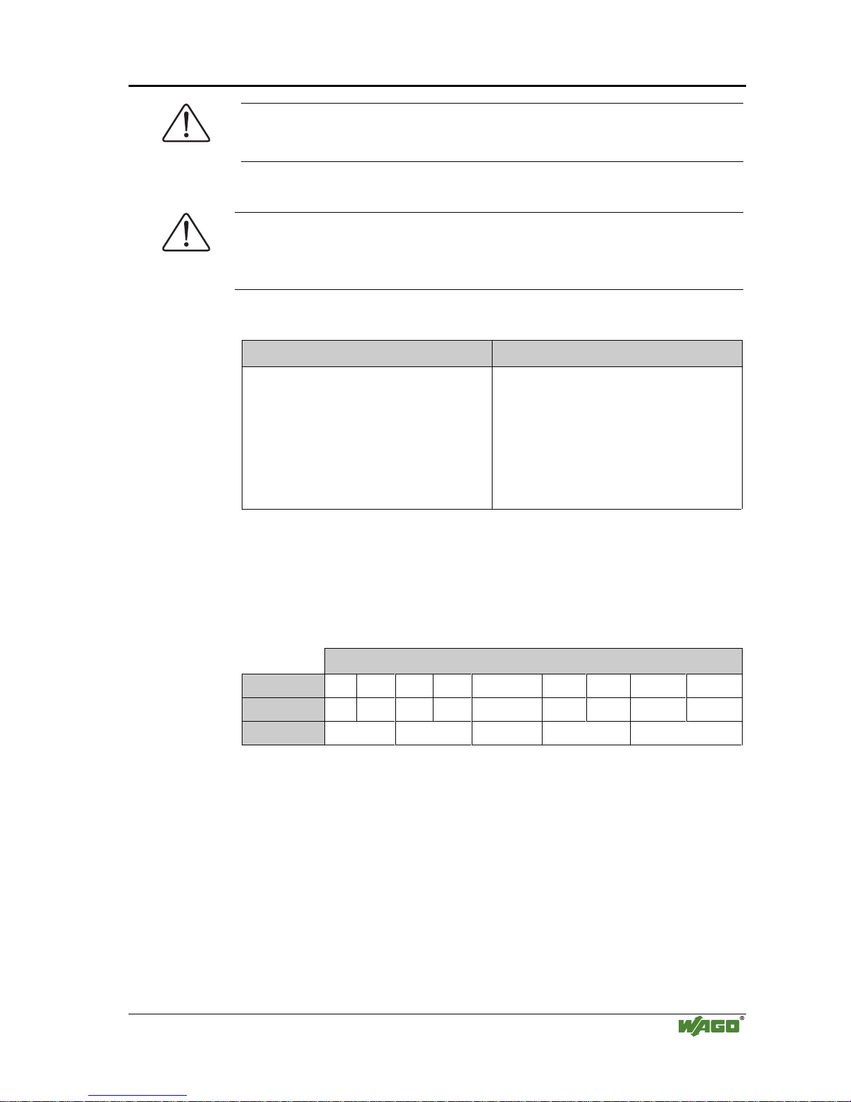
1.3 Symbols
Danger
Always observe this information to protect persons from injury.
Warning
Always observe this information to prevent damage to the device.
Attention
Marginal conditions must always be observed to ensure smooth operation.
ESD (Electrostatic Discharge)
Warning of damage to the components by electrostatic discharge. Observe the
precautionary measure for handling components at risk.
Note
Routines or advice for efficient use of the device and software optimization.
i
More information
References to additional literature, manuals, data sheets and INTERNET pages.
Page 7

Important comments • 3
Font conventions
Modular I/O System
ETHERNET TCP/IP
1.4 Font conventions
Italic
Names of paths and files are marked in italic.
i. e.: C:\programs\WAGO-I/O-CHECK
Italic
Menu items are marked in bold italic.
i. e.: Save
\
A backslash between two names markes a sequence of
menu items.
i. e.: File\New
END
Keys to press are marked in bold with small capitals.
i. e.: E
NTER
< >
Keys are marked bold within angle brackets.
i. e.: <F5>
Courier
Program codes are printed with the font Courier.
i. e.: END_VAR
1.5 Number notation
Number code Example Code
Decimal 100 normal notation
Hexadecimal 0x64 C notation
Binary ’100’
’0110.0100’
Within ’,
Nibble separated with dots
1.6 Abbreviation
AI
Analog Input
AO
Analog Output
DI
Digital Input
DO
Digital Output
I/O
Input/Output
ID
Identifier
PFC
Programmable Fieldbus Controller
Page 8

4 • The WAGO-I/O-SYSTEM 750
System Description
Modular I/O System
ETHERNET TCP/IP
2 The WAGO-I/O-SYSTEM 750
2.1 System Description
2.1.1 General
The WAGO-I/O-SYSTEMconsists of various components which are capable
of providing modular and application specific fieldbus nodes for various fieldbusses.
A fieldbus node (short: Node) consists in principle of a fieldbus coupler (short:
Coupler) or a programmable fielbus controller (short: Controller) at the front
end (1), a number of I/O modules (2) and an end module (3) which is placed at
the other end.
Fig. 2-1: Setting up a fieldbus node with the WAGO-I/O-SYSTEM g012900x
2.1.2 Coupler/Controller (1)
The Coupler/Controller forms the link between the fieldbus and the field devices with their I/O functions. All control functions required for the faultless
operation of the I/O functions are carried out by the Coupler/Controller. The
connection to different fieldbus systems is established by each of the corresponding Coupler/Controller, e.g. for PROFIBUS, INTERBUS, CAN,
MODBUS etc. In this way a change of the fieldbus system is possible.
The programmable fieldbus controller 750-842 combines the ETHERNET
TCP/IP functionality of the fieldbus coupler 750-342 with the functionality of
a Programmable Logic Control (PLC). Programming of the application is done
with WAGO-I/O-PRO in accordance with IEC 61131-3, covering all 5 programming languages. The programmer can access all fieldbus and I/O data.
Page 9

The WAGO-I/O-SYSTEM 750 • 5
System Description
Modular I/O System
ETHERNET TCP/IP
Characteristics and use of the Controllers:
• The use of decentralized control can better support a PLC or PC
• Complex applications can be divided into multiple tasks
• Programmable response in the event of a fieldbus failure
• Signal pre-processing reduces fieldbus transmissions
• Peripheral equipment can be controlled directly, resulting in faster system
response times
• Simple, self-sufficient control
2.1.3 I/O Modules (2)
In the I/O modules, the incoming process data is converted. Corresponding to
the different requirements, special I/O modules are available for a variety of
functions. There are digital and analog inputs and outputs and modules for
special functions (Counter modules, Terminal blocks for encoder and resolvers
and communication modules).
2.1.4 End Module (3)
An End Module is needed for faultless operation of the node. The termination
module is always placed as the last module in order to obtain a termination of
the fieldbus node. This module has no I/O function.
Page 10
6 • The WAGO-I/O-SYSTEM 750
Installation
Modular I/O System
ETHERNET TCP/IP
2.2 Installation
2.2.1 Safty notes
ESD (Electrostatic Discharge)
The modules are equipped with electronic components which may be destroyed by electrostatic discharge.When handling the modules, ensure that the
environment (persons, workplace and packing) is well grounded. Avoid
touching conductive components, e.g. gold contacts.
Attention
Switch off the system prior to working on bus modules!
2.2.2 Mechanical Installation
All system components can be snapped directly on a carrier rail in accordance
with the European standard EN 50022 (DIN 35).
Attention
Ensure that the carrier rail is fastened with countersunk head screws or blind
rivets as the snap-on foot of the I/O components extends onto the carrier rail.
The installation is simple and space saving. All modules have the same shape
to minimize the project commitment.
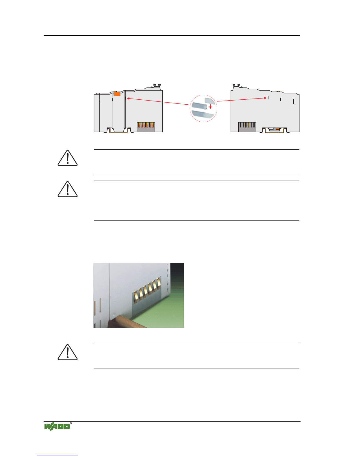
The reliable positioning and connection of the coupler and the individual I/O
modules is made using a tongue and groove system. Due to the automatic
locking, the individual components are securely seated on the rail after installing.
Page 11

The WAGO-I/O-SYSTEM 750 • 7
Installation
Modular I/O System
ETHERNET TCP/IP
To secure the coupler/controller against moving sideways, lock it with the orange colored locking disc on the carrier rail. To lock, insert a screwdriver into
the top groove of the locking disc and press.
To pull out the fieldbus coupler, release the locking disc by pressing on the
bottom groove with a screwdriver and then pull the orange colored unlocking
lug.
Fig. 2-2: Couple r/Controller and unlocking lug G012912d
It is also possible to release an individual I/O module from the unit by pulling
the unlocking lug.
Fig. 2-3: Releasing a I/O Module p0xxx01x
Danger
Ensure that an interruption of the ground will not result in a condition which
could endanger a person or equipment!
Page 12
8 • The WAGO-I/O-SYSTEM 750
Installation
Modular I/O System
ETHERNET TCP/IP
Self-cleaning power jumper contacts conduct the supply voltage for the field
side. They are located on either side of the modules. The female contacts on
the right-hand side of the fieldbus coupler and the bus modules are designed as
spring contacts to protect against accidental contact. Male contacts are located
on the left-hand side of the bus modules.
Pos. 1
Pos. 2
Fig. 2-4: Power Jumper Contacts g01xx00d
Danger
The power contacts have sharp-edges. Handle the module carefully to prevent
injury.
Attention
Please take into consideration that some bus modules have no or only some
power jumper contacts. The design of some modules does not physically allow for assembling them in rows as the grooves for the male contacts are
closed at the top.
The data contacts are designed as self-cleaning gold spring contacts which
automatically produce a secure connection.
Fig. 2-5: Data contacts p0xxx07x
Warning
Do not connect the I/O module to gold spring contacts in order to avoid tarnishing or scratching!
Page 13
The WAGO-I/O-SYSTEM 750 • 9
Electrical Installation
Modular I/O System
ETHERNET TCP/IP
2.3 Electrical Installation
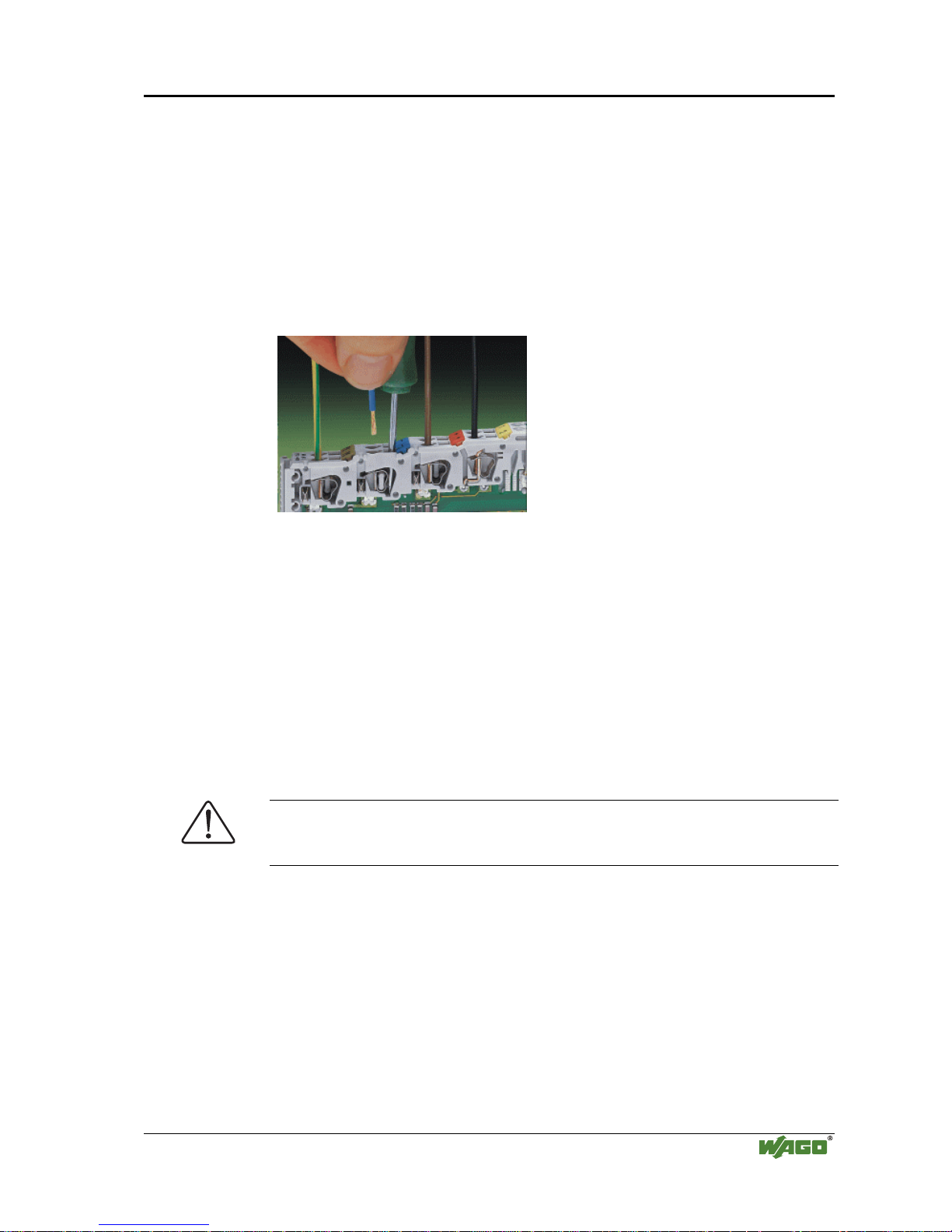
2.3.1 Wire Connection
Conductors with a cross section of 0.08 to 2.5 mm² (AWG 28-12) can be connected using a CAGE CLAMP connection to achieve a vibration resistant,
fast and maintenance free connection. To actuate CAGE CLAMP enter an
actuation tool in the opening above the connection. Following this, enter the
conductor in the corresponding opening. The conductor is clamped securely
with the removal of the actuation tool.
Fig. 2-6: Inserting conductor end p0xxx06x
The clamping force adjusts automatically to the cross section. The full surface
of the CAGE CLAMP pressure is applied against the conductor without
damaging it. Conductor deformation is compensated for and self-loosening is
avoided. The transition point between the conductor and the CAGE CLAMP
is protected against corrosive influences. The connection can be made quickly
and is also maintenance free, saving the costs for a periodic checking of terminal connections.
Two carrier rail contacts responsible for the electrical contact between the
grounded carrier rail and the controller are fitted underneath the coupler/controller.
Attention
Ensure a perfect contact point between carrier rail contacts and carrier rail.
The carrier rail must be grounded.
Page 14

10 • The WAGO-I/O-SYSTEM 750
Electrical Installation
Modular I/O System
ETHERNET TCP/IP
2.3.2 Change fuse
Some Power supply modules of the WAGO-I/O-SYSTEM 750 are equipped
with a fuse holder. To isolate the modules to the right of the power supply, the
fuse can be removed from the fuse holder. For this insert a screw driver into
one of the slits available on each side and lift the holder.
Fig. 2-7: Removing the fuse holder p0xxx05x
The fuses can be removed from or inserted into the fuse holder cover. Then
push the fuse holder back into the original position.
Fig. 2-8: Opening the fuse holder p0xxx03x
Fig. 2-9: Change fuse p0xxx04x
Page 15

The WAGO-I/O-SYSTEM 750 • 11
Power supply
Modular I/O System
ETHERNET TCP/IP
2.4 Power supply
750-630 750-650750-400 750-410 750-403 750-454 750-467 750-461
750-612
750-512 750-512 750-513 750-610 750-552750-550 750-600750-616
~
24V 24V 24V
230V
1
2
Fig. 2-10: Power supply g01xx02x
1 – Power supply System
2 – Power supply Field-side
The power supply on the field side is electrically isolated from the system supply. In this manner sensors and actuators can be supplied and fused by a separate voltage source.
If a non-regulated power supply is used for the coupler/controller electronics
24 V voltage supply, it must be filtered through a capacitor (200 µF per 1 A
load current). A back-up capacitor module (Order-No. 288-824) was developed for the WAGO-I/O-SYSTEM. This module serves to regulate a noisy
24 V DC voltage supply and to keep the ripple voltage within specified limits.
These fluctuations could be caused by a voltage interruption on the primary
side, a secondary side overload or the switching of ”non quenched“ inductance
or capacitance.
Warning
The supply module’s + and –, which are permanently integrated on the
buscouplers, must be supplied with 24 V DC only.
120 V AC and 230 V AC can only be supplied via modules 750-609, 750-611
and 750-612!
Warning
The ground (earth) field side contact should be disconnected when testing the
isolation. Otherwise the results could be wrong or the module could be destroyed.
Page 16

12 • The WAGO-I/O-SYSTEM 750
Power supply
Modular I/O System
ETHERNET TCP/IP
2.4.1 System supply voltage
The system supply voltage (24 V DC) is filtered with a voltage regulator before powering the coupler electronics as well as to the internal bus. Electrical
isolation from the external fieldbus system depends on the type of Coupler/Controller.
The internal bus includes the internal communication between the coupler/controller and the bus modules as well as the power supply for the bus
modules. The power supply is limited to a maximum value. This value depends on the type of Coupler/Controller. If the sum of the internal power consumption of all bus modules exceeds this value, it is necessary to add additional internal system supply modules (Order-No. 750-613).
The control electronics in the bus modules are powered by snap-fit mounting
the bus modules using the internal bus contacts. A reliable contact is assured
by the gold plated, self cleaning slide contacts. The removal of a bus module
will cause an interruption in communication to the following bus modules.
The coupler/controller identifies the interruption point and displays a corresponding fault message.
Warning
Removing or inserting the I/O modules with the voltage applied can lead to
undefined conditions. For this reason only remove the I/O modules when isolated from the power supply!
Page 17

The WAGO-I/O-SYSTEM 750 • 13
Power supply
Modular I/O System
ETHERNET TCP/IP
2.4.2 Supply Voltage Field Side
The voltage is automatically supplied when the I/O modules are snapped together. Self-cleaning power jumper contacts (P.J.C.s) ensure safe connections.
The current capacity of the power contacts is 10 A max.
The PE contact is a preceding ground (earth) contact corresponding to the
standards which can be used as a protective earth. The contact has a leakage
capacity of 125 A.
Warning
Produce a low impedance connection from the carrier rail to the PE contact
point in the cabinet.
Attention
Depending on the I/O function, some modules do not have P.J.C.s. It is important to note this when assembling a node. Many modules require field side
power, many do not. Please review the circuit diagrams of the individual modules. An additional power supply module may be necessary.
Refer to the individual terminal/module data sheets!
When adding a power supply module, the field supply is always interrupted at
the power contacts. From this point a new power supply is made, which can
also include a potential change. This feature guarantees a high degree of system flexibility.
Page 18

14 • The WAGO-I/O-SYSTEM 750
Manufacturing Number
Modular I/O System
ETHERNET TCP/IP
2.5 Manufacturing Number
The production number is part of the lateral marking on the component. The
number contains the production date, the software version and the hardware of
the component.
Hansastr. 27
D-32423 Minden
ITEM-NO.:750-400
2DI 24V DC 3.0ms
0.08-2.5mm
2
0V 24V DI1
Di2
PATENTS PENDING
II3G
KEMA 01ATEX1024 X
EEx nA II T4
CL I DIV 2
Grp. A B C D
op temp code T4A
24V DC
AWG 28-14
55°C max ambient
LISTED 22ZA AND 22XM
24246
0901--02----03
9
0
1
-
-
0
2
0
0
Manufacturing Number
Calendar
week
Year Software
version
Hardware
version
Fig. 2-11: Manufacturing Number g01xx09e
The remaining digits and characters represent internal information for
WAGO Kontakttechnik GmbH.
As of calendar week 43/2000, the production number is also printed on the
cover of the configuration and programming interface of the fieldbus coupler
or controller.
Page 19
The WAGO-I/O-SYSTEM 750 • 15
Technical Data
Modular I/O System
ETHERNET TCP/IP
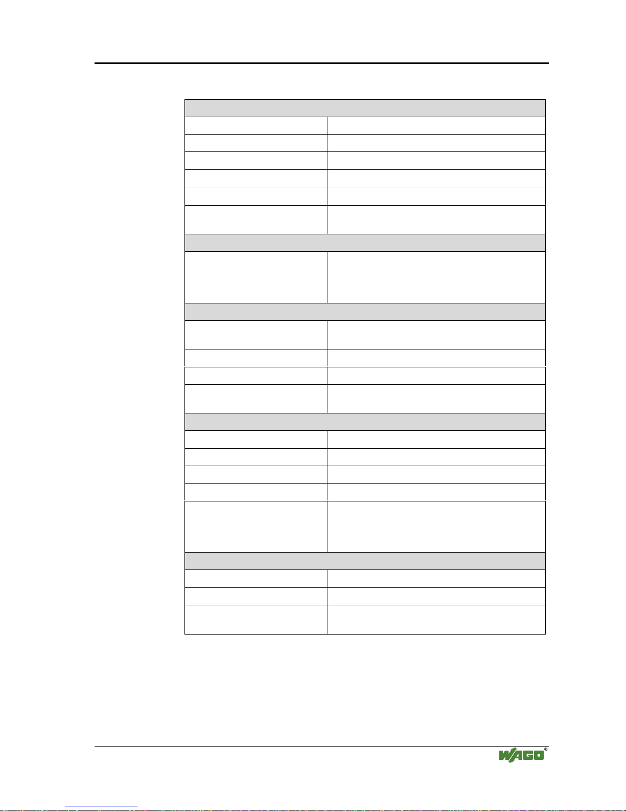
2.6 Technical Data
Mechanic
Material Polycarbonate, Polyamide 6.6
Installation on DIN 35 with interlock
modular by double featherkey-dovetail
Mounting position any position
Length of entire node
≤ 831 mm
Marking marking label type 247 and 248
paper marking label 8 x 47 mm
Wire range
Wire range CAGE CLAMP® Connection
0,08 mm² ... 2,5 mm²
AWG 28-14
8 – 9 mm Stripped length
Contacts
Power jumpers contacts blade/spring contact
self-cleaning
Current via power contacts
max
10 A
Voltage drop at I
max
< 1 V/64 modules
Data contacts slide contact, hard gold plated
1,5µ, self-cleaning
Environmental conditions
Operating temperature 0 °C ... 55 °C
Storage temperature -20 °C ... +85 °C
Relative humidity 95 % without condensation
Resistance to harmful substances acc. to IEC 60068-2-42 and IEC 60068-2-43
Special conditions Ensure that additional measures for components are
taken, which are used in an environment involving:
– dust, caustic vapors or gases
– ionizing rad i ation.
Mechanical strenght
Vibration resistance acc. to IEC 60068-2-6
Shock resistance acc. to IEC 60068-2-27
Free fall acc. to IEC 60068-2-32
≤ 1m (module in original packing)
Page 20

16 • The WAGO-I/O-SYSTEM 750
Technical Data
Modular I/O System
ETHERNET TCP/IP
Safe electrical isolation
Air and creepage distance acc. to IEC 60646-1
Degree of protection
Degree of protection IP 20
Electromagnetic compatibility*
Directive Test values Strength
class
Evaluation
criteria
Immunity to interference acc. to EN 50082-2 (95)
EN 61000-4-2 4kV/8kV (2/4) B
EN 61000-4-3 10V/m 80% AM (3) A
EN 61000-4-4 2kV (3/4) B
EN 61000-4-6 10V/m 80% AM (3) A
Emmission to interference acc. to
EN 50081-2 (94)
Measuring
distance
Class
EN 55011 G% 9P (30m) A
G% 9P
* Exception: 750-630, 750-631
Dimensions
51
24V 0V
+
+
-
-
PE PE
01
02
C
D
B
A
C
D
B
A
C
D
B
A
C
D
B
A
C
D
B
A
100
12
24
64
35
65
Fig. 2-12: Dimensions g01xx05d
Page 21

Fieldbus coupler / controller • 17
Fieldbus coupler 750-342
Modular I/O System
ETHERNET TCP/IP
3 Fieldbus coupler / controller
3.1 Fieldbus coupler 750-342
This chapter includes:
3.1.1 Description .....................................................................................18
3.1.2 Hardware ........................................................................................19
3.1.2.1 View......................................................................................... 19
3.1.2.2 Device supply .......................................................................... 20
3.1.2.3 Fieldbus connection................................................................. 20
3.1.2.4 Display elements...................................................................... 21
3.1.2.5 Configuration interface............................................................ 21
3.1.2.6 Hardware address (MAC-ID) .................................................. 21
3.1.3 Operating system............................................................................22
3.1.4 Process image.................................................................................23
3.1.4.1 Example of a process input image...........................................24
3.1.4.2 Example of a process output image.........................................25
3.1.4.3 Process data architecture for MODBUS/TCP .........................26
3.1.5 Data exchange.................................................................................31
3.1.5.1 Memory areas ..........................................................................32
3.1.5.2 Addressing...............................................................................32
3.1.5.3 Data exchange between MODBUS master and I/O modules..34
3.1.6 Starting up ETHERNET TCP/IP fieldbus nodes............................35
3.1.6.1 Note the MAC-ID and establish the fieldbus node.................. 35
3.1.6.2 Connecting PC and fieldbus node............................................35
3.1.6.3 Determining IP addresses ........................................................ 36
3.1.6.4 Allocating the IP address to the fieldbus node ........................ 36
3.1.6.5 Testing the function of the fieldbus node................................ 39
3.1.6.6 Reading out the information as HTML pages..........................40
3.1.7 LED Display................................................................................... 41
3.1.7.1 Blink code................................................................................ 41
3.1.7.2 Fieldbus status .........................................................................42
3.1.7.3 Node status...............................................................................42
3.1.7.4 Fault message via blink code from the I/O-LED.....................43
3.1.8 Fault behavior................................................................................. 45
3.1.8.1 Fieldbus failure........................................................................45
3.1.8.2 Internal bus fault...................................................................... 45
3.1.9 Technical Data................................................................................ 46
Page 22

18 • Fieldbus coupler 750-342
Description
Modular I/O System
ETHERNET TCP/IP
3.1.1 Description
The fieldbus coupler 750-342 displays the peripheral data of all I/O modules in
the WAGO-I/O-SYSTEM 750 on ETHERNET.
All sensor input signals are grouped in the coupler (slave) and transferred to
the higher ranking controls (master) via the fieldbus. Process data linking is
performed in the higher ranking controls. The controls put out the resulting
data to the actuators via the bus and the node.
To be able to transmit process data via ETHERNET, the coupler supports a series of network protocols. Process data are exchanged with the aid of the
MODBUS/TCP protocol.
Once the ETHERNET TCP/IP fieldbus coupler is connected, the coupler detects all I/O modules connected to the node and creates a local process image
on this basis, which can be a mixed arrangement of analog (word-by-word data
exchange) and digital (bit-by-bit data exchange) modules.
The local process image is subdivided into an input and an output data area.
The data of the analog modules are mapped into the process image in the order
of their position downstream of the bus coupler.
The bits of the digital modules are grouped into words and also mapped into
the process image as soon as mapping of the analog modules is completed.
When the number of digital I/O’s exceeds 16 bits, the coupler automatically
starts the next word.
Also note that all process images start at WORD 0.
Information on configuration, status and the I/O data of the fieldbus node are
stored in the fieldbus coupler as HTML pages. These pages can be seen via a
standard WEB browser by typing the IP address, that you assigned the coupler,
into the Address field of your web browser.
Page 23
Fieldbus coupler 750-342 • 19
Hardware
Modular I/O System
ETHERNET TCP/IP
3.1.2 Hardware
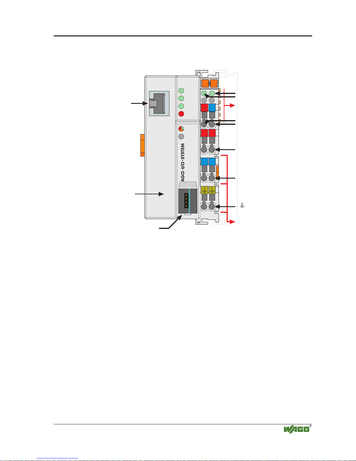
3.1.2.1 View
24V 0V
++
--
01 02
750-342
ON
LINK
TxD/RxD
I/O
ETHERNET
C
D
B
A
ERROR
0V
status
voltage supply
-power jumper contacts
-system
data contacts
supply
24V
0V
supply via
power jumper contacts
24V
0V
power jumper contacts
fieldbus
connection
RJ 45
configuration
interface
flap
open
Fig. 3-1: Fieldbus coupler ETHERNET TCP/IP G034200e
The fieldbus coupler is comprised of:
• Supply module which includes the internal system supply as well as power
jumper contacts for the field supply via I/O module assemblies.
• Fieldbus interface with the bus connection RJ 45
• Display elements (LED’s) for status display of the operation, the bus com-
munication, the operating voltages as well as for fault messages and diagnosis
• Configuration Interface
• Electronics for communication with the I/O modules (internal bus) and the
fieldbus interface
Page 24
20 • Fieldbus coupler 750-342
Hardware
Modular I/O System
ETHERNET TCP/IP
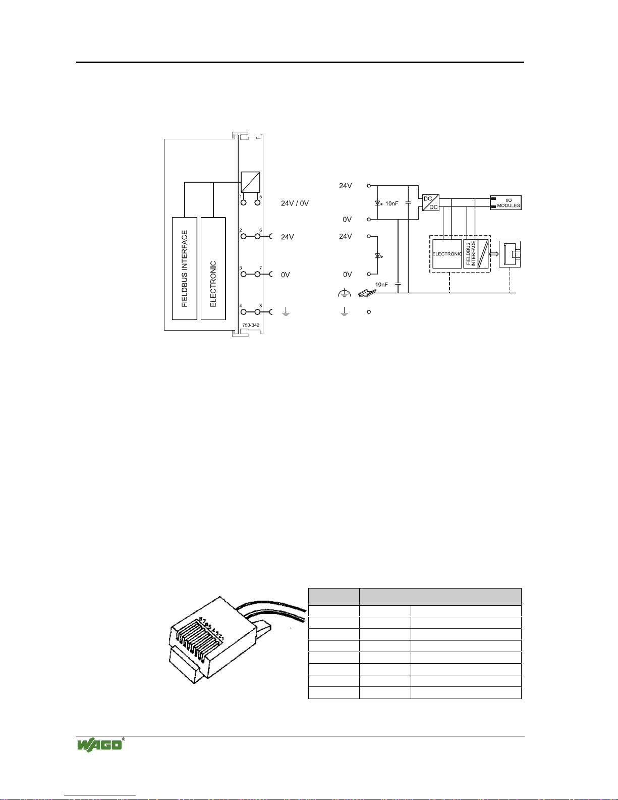
3.1.2.2 Device supply
The supply is made via terminal bocks with CAGE CLAMP® connection. The
device supply is intended both for the system and the field units.
Fig. 3-2: Device supply G034201e
The integrated internal system supply module generates the necessary voltage
to supply the electronics and the connected I/O modules.
The fieldbus interface is supplied with electrically isolated voltage from the
internal system supply module.
3.1.2.3 Fieldbus connection
Connection to the fieldbus is by an RJ45 connector. A category 5,
shielded/unshielded twisted pair cable (S-UTP) with an impedance of 100
Ohm ±15% is mandatory as a connecting line for the 10BaseT Interface.
The connection point is physically lowered for the coupler/controller to fit in
an 80 mm high switch box once connected.
The electrical isolation between the fieldbus system and the electronics is
achieved by means of DC/DC converters and optocouplers in the fieldbus interface.
Contact Signal
1 TD + Transmit +
2 TD - Transmit 3 RD + Receive +
4free
5free
6 RD - Receive 7free
8free
Fig. 3-3: RJ45-connector and RJ45 connector configuration
Page 25
Fieldbus coupler 750-342 • 21
Hardware
Modular I/O System
ETHERNET TCP/IP
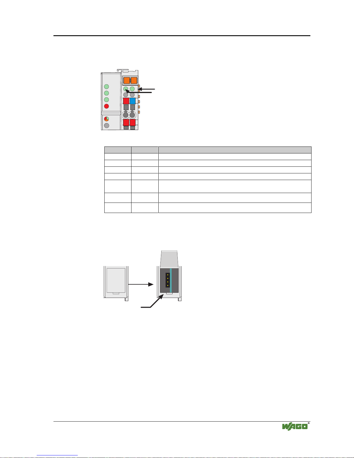
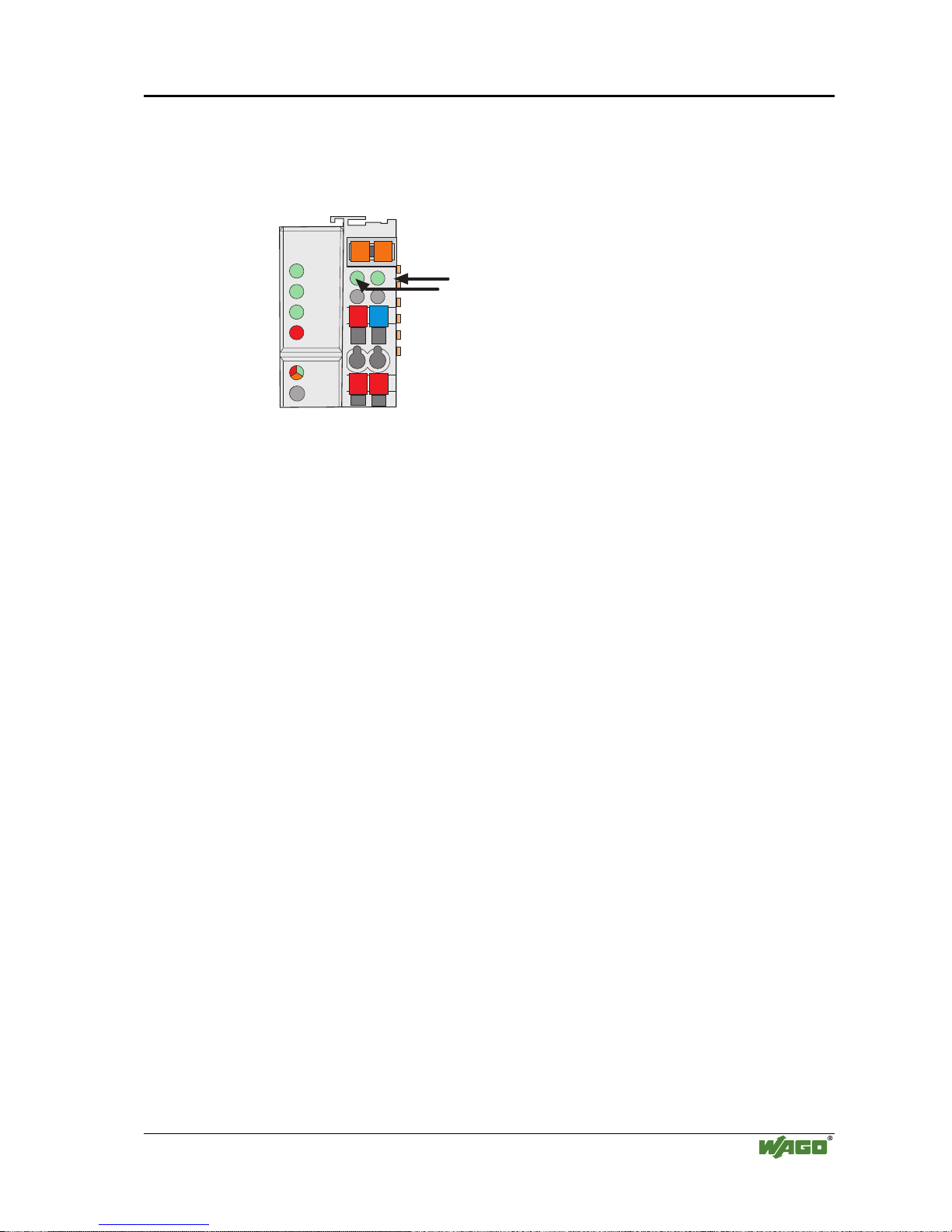
3.1.2.4 Display elements
The operating condition of the fieldbus coupler or node is signaled via light diodes (LED).
24V
0V
++
01 02
ON
LINK
TxD/RxD
I/O
ETHERNET
C
D
B
A
ERROR
status
voltage supply
-power jumper contacts
-system
Fig. 3-4: Display elements 750-342 G012901e
LED Color Meaning
ON green Fieldbus initialization is correct
LINK green Link to a physical network exists
TxD/RxD green Data exchange taking place
ERROR red Error on the fieldbus
IO red /green
/ orange
The ’I/O’-LED indicates the operation of the node and signals faults
encountered
A green Status of the operating volta ge – system
C green Status of the operating voltage – power jumper contacts
3.1.2.5 Configuration interface
The configuration interface used for the communication with WAGO-I/OCHECK or for firmware download is located behind the cover flap.
Configuration
interface
open
flap
Fig. 3-5: Configurat ion interface g012945e
The communication cable (750-920) is connected to the 4 pole header.
3.1.2.6 Hardware address (MAC-ID)
Each WAGO ETHERNET fieldbus coupler is provided from the factory with a
unique and internationally unambiguous physical ETHERNET address, also
referred to as MAC-ID (Media Access Control Identity). This address is to be
found on the rear of the coupler and on an adhesive tear-off label on the side of
the coupler. The address has a fixed length of 6 Bytes (48 Bit) and contains the
address type, the manufacturer’s ID, and the serial number.
Page 26

22 • Fieldbus coupler 750-342
Operating system
Modular I/O System
ETHERNET TCP/IP
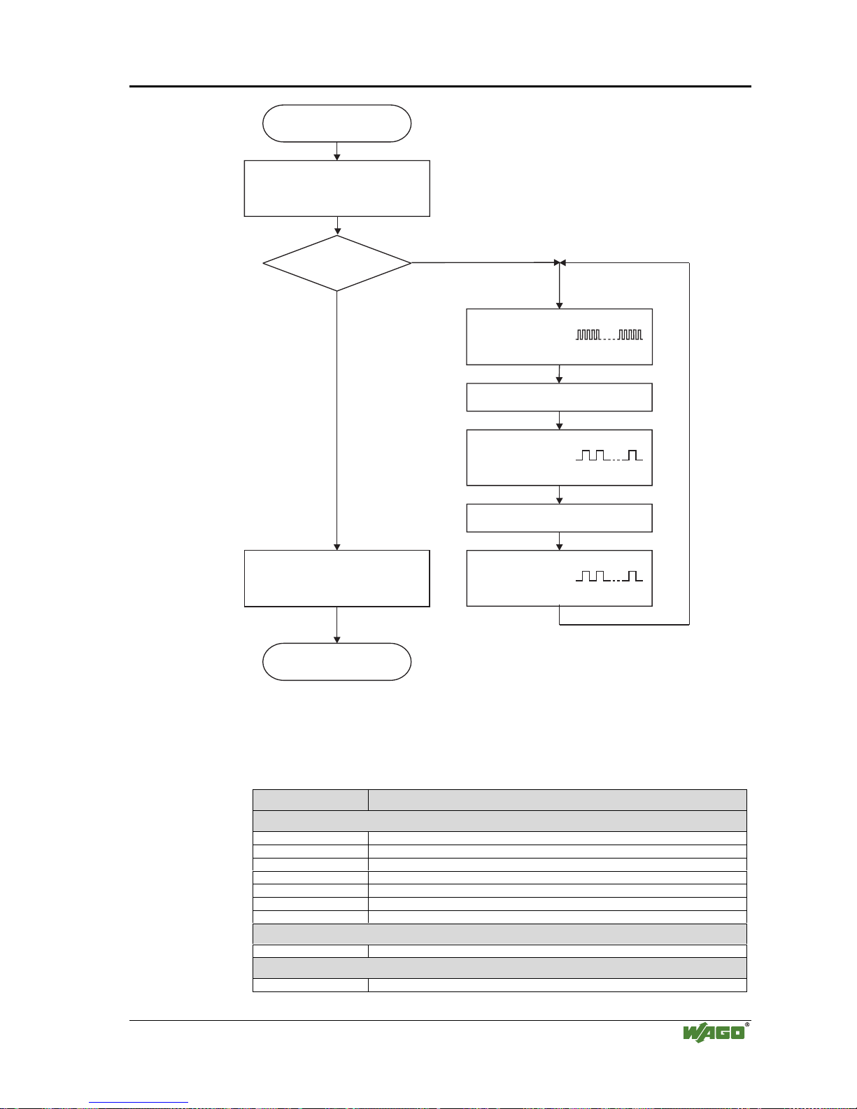
3.1.3 Operating system
Following is the configuration of the master activation and the electrical installation of the fieldbus station to start up the system.
After switching on the supply voltage, the coupler determines the I/O modules
and the present configuration.
In the event of a fault, the coupler changes to the "Stop" condition. The "I/O"
LED flashes red. After a fault free start up, the coupler changes to the "Fieldbus start" status and the "I/O" LED lights up green.
Stop
red “I/O” LED indicates
blink code
Switching on the
supply voltage
Test o.k.?
No
Yes
Fieldbus coupler is
in operating mode
“I/O” LED is shining green
Initialization,
Determination of the I/O modules
and the configuration,
“I/O” LED is blinking red
Fig. 3-6: Operating system 750-342 g012920e
Page 27

Fieldbus coupler 750-342 • 23
Process image
Modular I/O System
ETHERNET TCP/IP
3.1.4 Process image
After switching on, the coupler recognizes all I/O modules plugged into the
node which supply or wait for data (data width/bit width > 0). Analog and
digital I/O modules can be mixed on the same node.
Note
For the number of input and output bits or bytes of the individually activated
I/O modules, please refer to the corresponding I/O module description.
The coupler produces an internal process image from the data width and the
type of I/O module as well as the position of the I/O modules in the node. It is
divided into an input and an output data area.
The data of the digital I/O modules is bit orientated, i.e. the data exchange is
made bit for bit. The analog I/O modules are representative for all byte orientated I/O modules, i.e. those where the data exchange is made byte for byte.
These I/O modules include for example the counter modules, I/O modules for
angle and path measurement as well as the communication modules.
The data of the I/O modules is separate from the local input and output process
image in the sequence of their position after the coupler in the individual process image.
First, all the byte oriented bus modules and then the bit oriented bus modules
are stored in the process image. The bits of the digital modules are grouped to
form bytes. As soon as the number of digital I/O’s exceeds 8 bits, the coupler
automatically starts the next byte.
Note
A process image restructuring may result if a node is changed. In this case the
process data addresses also change in comparison with earlier ones. In the
event of adding modules, take the process data of all previous modules into
account.
The coupler provides a storage area of 256 words each (word 0 - 255) for the
physical input and output data.
Page 28
24 • Fieldbus coupler 750-342
Data exchange
Modular I/O System
ETHERNET TCP/IP
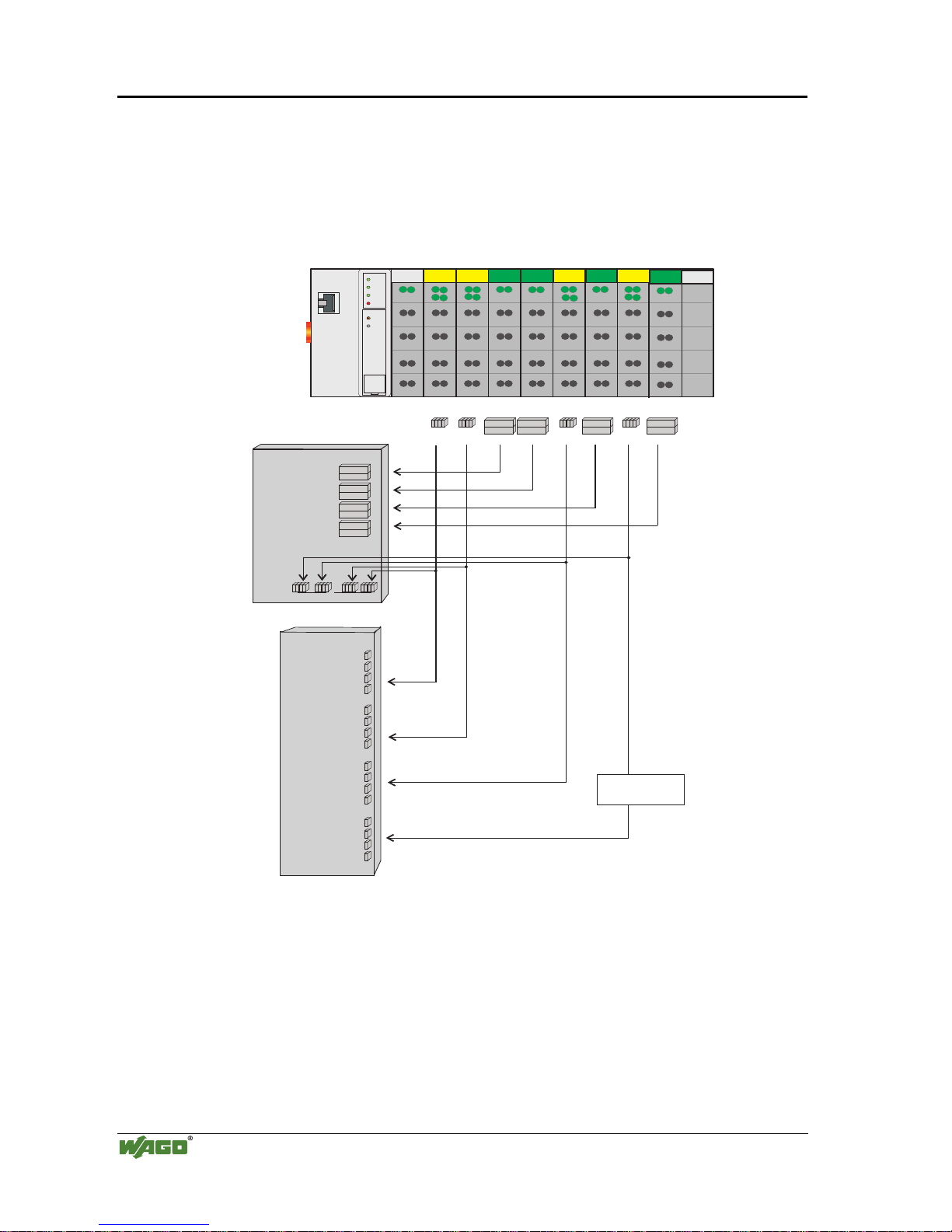
3.1.4.1 Example of a process input image
The following figure is an example of a process input image.
The configuration comprises of 16 digital and 8 analog inputs.
The process image thus has a data length of 8 words for the analog and 1 word
for the digital inputs, i.e. 9 words in total.
Bit 1
Bit 4
Word2
Word1
Word2
Word1
Word2
Word1
Word2
Word1
Word2
Word1
Word2
Word1
1
4
1411
4
1
ON
LINK
TxD/RxD
ERROR
Ethernet
750-842
I/O
WAGO
ßI/O
ßSYSTEM
DI
DI
DI
DI
AI
AI
AI
AI
Word2
Word1
Word2Word2
Word1
Highbyte
Lowbyte
0x0003
0x0002
0x0001
0x0000
0x0005
0x0004
0x0007
0x0006
0x0008
0x0001
0x0000
0x0003
0x0002
0x00040x0004
0x0008
0x000C
0x00050x0005
0x0009
0x000D
0x00060x0006
0x000A
0x000E
0x00070x0007
0x000B
0x000F
Process input image
(Word)
MODBUS addresses
Process input image
(Bit)
Input modules 750- 402 402 472 472 402 476 402 476
DI: Digital Input
AI:Analog Input
MODBUS addresses
Fig. 3-7: Example of a process input image G012914e
Page 29

Fieldbus coupler 750-342 • 25
Data exchange
Modular I/O System
ETHERNET TCP/IP
3.1.4.2 Example of a process output image
The following example for the process output image comprises of 2 digital and
4 analog outputs.
It comprises of 4 words for the analog and 1 word for the digital outputs, , i.e.
5 words in total.
In addition, the output data can be read back by means of an offset of 200hex
(0x0200) added to the MODBUS address.
Bit 1
Bit 2
Word2
Word1
Word2
Word1
Word2
Word1
Word2
Word1
Word2
Word1
Word2
Word1
0x0003 / 0x0203
0x0002 / 0x0202
0x0001 / 0x0201
0x0000 / 0x0200
0x0004 /
0x0204
0x0203
0x0202
0x0201
0x0200
0x0204
0x0000 / 0x0200
0x0001 / 0x0201
0x0200
0x0201
ON
LINK
TxD/RxD
ERROR
Ethernet
750-342
I/O
WAGO
ßI/O
ßSYSTEM
Highbyte
Lowbyte
Highbyte
Lowbyte
AO
DO
AO
MODBUS addresses
MODBUS addresses
MODBUS addresses
MODBUS addresses
Process output image
(Word)
Process input image
(Word)
Process output image
(Bit)
Process input image
(Bit)
DO: Digital Output
AO: Analog Output
Output modules 750 - 501 550 550
Fig. 3-8: Example of a process output image G012915e
Page 30

26 • Fieldbus coupler 750-342
Data exchange
Modular I/O System
ETHERNET TCP/IP
3.1.4.3 Process data architecture for MODBUS/TCP
For some bus modules or their variations the process data architecture is specific for the fieldbus coupler used.
In the case of the ETHERNET coupler with MODBUS/TCP, the control/status
byte is always masked in addition to the data bytes. This is required for the
two-directional data exchange of the bus module with the higher-ranking control system. The control byte is transmitted from the control system to the
module and the status byte from the module to the control system. This allows,
for example, the display of overshooting or undershooting of the area.
Attention
Please refer to the respective bus module description in Chapter 4 "I/O modules" for the specific architecture of the control/status byte.
The following shows the representation of some selected modules in the process image.
In the examples, the order in which the modules are physically arranged in the
node reflects the order in the image table starting with register address 0x0000.
If the module is at any other position in the fieldbus node, the process data of
all previous byte-wise oriented modules has to be taken into account, resulting
in a basic register address for the module in the process image. The mentioned
offset will be added to this basic address for addressing its process data words.
If an analog input or output module is added, it takes up 2 x 16 Bit input of
output data. Therefore the first available digital point would be at word 2
keeping in mind that all process image addressing starts at WORD 0.
With the ETHERNET fieldbus coupler with MODBUS/TCP TCP, the process
image is word aligned (word-alignment) and the control/status byte is always a
low byte.
Page 31

Fieldbus coupler 750-342 • 27
Data exchange
Modular I/O System
ETHERNET TCP/IP
3.1.4.3.1 750-404, /000-00X Counter modules
This process data architecture holds true for the counter modules 750-404,
750-404/000-001, 750-404/000-002 and 750–404/000-004.
Item-No.: Description:
750-404 Up/Down Counter
750-404/000-001 2 Channel Up Counter with enable input
750-404/000-002 Peak Time Counter
750-404/000-004 Up/Down Counter (switching outputs)
The data format of the counter modules five bytes is mapped out by the module as four data bytes and one additional control/status byte. The module
supplies a 32 bit counter-output. Three words each in the process image are
occupied with word-alignment.
Address Bytes Comment Module
Offset High Low
0 C/S Control-/ Status byte
1D1D0
2D3D2
Data bytes
Module 1:
750-404,
750-404/000-001,
750-404/000-002,
750-404/000-004
3 User data User data Data bytes
Module 2:
Analog module Channel 1
4 User data User data Data bytes
Module 2:
Analog module Channel 2
... ... ... ... ...
The input bytes D0 to D3 form the 32 bit counter-output.
In the output bytes D0 to D3, the initial value of the counter can be set.
3.1.4.3.2 750-404/000-005 2 Channel Up Counter 16 Bit
The data format of the counter modules five bytes is mapped out by the module as four data bytes and one additional control/status byte. Three words
each in the process image are occupied with word-alignment .
Address Bytes Comment Module
Offset High Low
0 C/S Control/ Statusbyte
1 D1 D0 Data bytes Counter 1
2 D3 D2 Data bytes Counter 2
Module 1:
750-404/000-005
3 User data User data Data bytes
Module 2:
Analog module Channel 1
4 User data User data Data bytes
Module 2:
Analog module Channel 2
... ... ... ... ...
Page 32

28 • Fieldbus coupler 750-342
Data exchange
Modular I/O System
ETHERNET TCP/IP
The input bytes D0 and D1 form the 16 bit reading of counter 1 and the input
bytes D2 and D3 form the 16 bit reading of counter 2.
When setting the counter, the load value of counter 1 is transferred in the output bytes D0 and D1. The load value of counter 2 is transferred respectively in
the output bytes D2 and D3.
3.1.4.3.3 750-511, /000-002 2-Channel Digital Pulsewidth module
This process data architecture holds true for the 2 Channel Pulsewidth modules 750-511 and 750–511/000-002.
Item-No.: Description:
750-511 2DO 24V DC 0.1A Pulsewidth
750-511/000-002 2DO 24V DC 0.1A Pulsewidth 100Hz
The process image of the 750-511 and 750-511/000-002 appears with 6 bytes
of input and 6 bytes of output data. Four words in the process image are occupied with word-alignment .
Address Bytes Comment Module
Offset High Low
0 C/S-0 Control / Status byte
1 D1-0 D0-0
Data bytes
Module 1 Channel 1:
750-511,
750-511/000-002
2 C/S-1 Control / Status byte
3 D1-1 D0-1 Data bytes
Module 1 Channel 2:
750-511,
750-511/000-002
4 User data User data Data bytes
Module 2:
Analog Module Channel 1
5 User data User data Data bytes
Module 2:
Analog Module Channel 2
... ... ... ... ...
3.1.4.3.4 750-630, /000-00X SSI encoder interface 24 Bit
This process data architecture holds true for the SSI encoder interface modules
750-630, 750-630/000-001 and 750–630/000-006.
Item-No.: Description:
750-630 SSI encoder interface 24Bit, 125kHz Gray code, alternative Data
format
750-630/000-001 SSI encoder interface 24Bit, 125kHz Binary code, alternative
Data format
750-630/000-006 SSI encoder interface 24Bit, 250kHz Gray code, alternative Data
format
Page 33

Fieldbus coupler 750-342 • 29
Data exchange
Modular I/O System
ETHERNET TCP/IP
The module is seen like an analog input with 2 x 16 Bit input data, i.e. with a
total of 4 bytes user data. With word-alignment 2 words are used in the input
area of the local process image.
Address Bytes Comment Module
Offset High Low
0D1D0
1D3D2
Data bytes
Module 1:
750-630,
750-630/000-001,
750-630/000-006
2 User data User data Data bytes
Module 2:
Analog module Channel 1
3 User data User data Data bytes
Module 2:
Analog module Channel 2
... ... ... ... ...
3.1.4.3.5 750-631, /000-001 Incremental Encoder Interface
This process data architecture holds true for the Incremental Encoder Interface
modules 750-631 and 750–631/000-001.
Item-No.: Description:
750-631 Incremental encoder interface, 4 times sampling
750-631/000-001 Incremental encoder interface, 1 times sampling
The bus module 750-631 and 750-631/000-001 002 appears with 6 bytes of
input and 6 bytes of output data and occupying 4 words each with word-alignment.
Address Bytes Comment Module
Offset High Low
0 C/S Control / Status byte
1 D1 D0 ead/set counter word
3 (D2)*
)
(period)
4 D4 D3 read latch word
Module 1:
750-631,
750-631/000-001
5 User data User data Data bytes
Module 2:
Analog module Channel 1
6 User data User data Data bytes
Module 2:
Analog module Channel 2
... ... ... ... ...
In the low byte, the control/status byte is on offset 0.
The data word D0/D1 contains the counter word (read/set), whereas the data
word D3/D4 contains the latch word (read).
*) In the operating mode of permanent period measurement, the period duration is in D2 together with D3/D4.
Page 34

30 • Fieldbus coupler 750-342
Data exchange
Modular I/O System
ETHERNET TCP/IP
3.1.4.3.6 750-650 RS232 Interface module,
750-651 TTY-,20 mA Current Loop,
750-653 RS485 Interface module
This process data architecture holds true for the modules 750-650, 750-651
and 750–653.
Item-No.: Description:
750-650 RS 232 C Interface 9600,n,8,1
750-651 TTY Interface, 20 mA Current Loop
750-653 RS485 Interface
The modules appear on the bus as a combined analog input and output module
with 3 x 16-bit input and output data, i.e. with a total of 4 bytes user data, occupying 2 words each with word-alignment.
Address Bytes Comment Module
Offset High Low
0D0C/S
Data
byte
Control /
Status byte
1D2D1
Data bytes
Module 1:
750-650,
750-651,
750-653
2 User data User data Data bytes
Module 2:
Analog module Channel 1
3 User data User data Data bytes
Module 2:
Analog module Channel 2
... ... ... ... ...
3.1.4.3.7 750-650/000-001 RS232 Interface module 5 Byte
The RS232 interface module 750-650 can also be operated with a data format
of 5 bytes and one Control/Status byte, i.e. a total of 6 bytes user data. For this
data format, order the variation with the part number 750-650/000-001, occupying 3 words each with word-alignment in the input and output area of the
process image.
Address Bytes Comment Module
Offset High Low
0D0C/S
Data
byte
Control /
Status byte
1D2D1
2D4D3
Data bytes
Module 1:
750-650/000-001
3 User data User data Data bytes
Module 2:
Analog module Channel 1
4 User data User data Data bytes
Module 2:
Analog module Channel 2
... ... ... ... ...
Page 35

Fieldbus coupler 750-342 • 31
Data exchange
Modular I/O System
ETHERNET TCP/IP
3.1.5 Data exchange
Process data exchange with the ETHERNET TCP/IP fieldbus coupler occurs
via the MODBUS/TCP protocol.
MODBUS/TCP works according to the master/slave principle. The master is a
superimposed control unit, i.e. a PC or a PLC device. The ETHERNET
TCP/IP couplers of the WAGO-I/O-SYSTEM are slave devices.
The master makes a query for communication. Through adressing, this query
can be sent to a specific node. The nodes receive the query and return a response to the master, depending on the kind of query.
A coupler can communicate with a certain number of simultaneous connections
(socket connections) to other network subscribers:
• 1 connection for HTTP (reading HTML pages from coupler) and
• 3 connections via MODBUS/TCP (reading or writing input and output data
from coupler).
The maximum number of simultaneous connections cannot be exceeded. If
further connections are to be made, terminate existing connections beforehand.
For a data exchange, the ETHERNET TCP/IP fieldbus coupler is equipped with
two interfaces:
• the interface to fieldbus (-master) and
• the interface to the bus modules.
Data exchange takes place between MODBUS master and the bus modules. The
master accesses the bus module data via implemented MODBUS functions.
Page 36
32 • Fieldbus coupler 750-342
Data exchange
Modular I/O System
ETHERNET TCP/IP
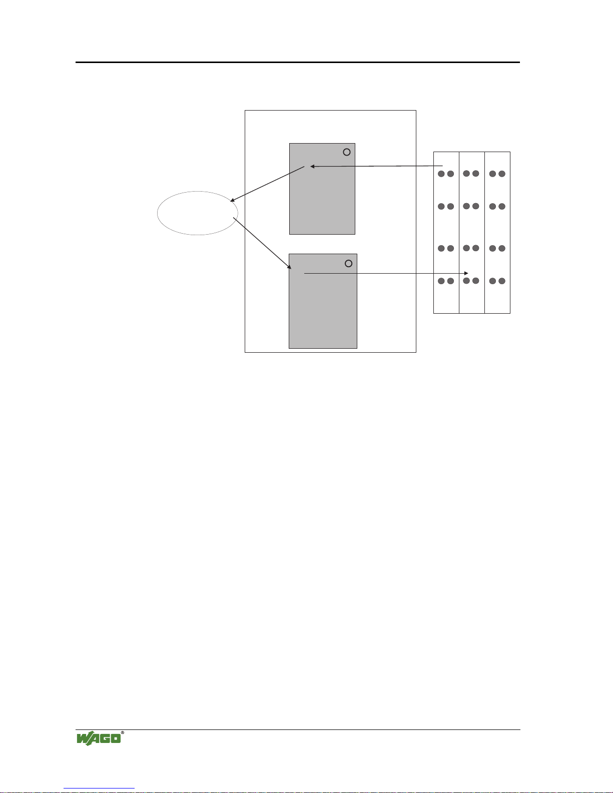
3.1.5.1 Memory areas
I
O
memory area
for input data
I/O modules
input
modules
word 255
output
modules
word 0
word 255
fieldbus
master
word 0
memory area
for output data
fieldbus coupler
1
2
Fig. 3-9: Memory areas and data exchange for a fieldbus coupler g012939e
The coupler process image contains the physical data of the bus modules in a
storage area for input data and in a storage area for output data (word 0 ... 255
each).
(1) The input module data can be read from the fieldbus side.
(2) In the same manner, writing on the output modules is possible from the
fieldbus side.
In addition, all output data of the ETHERNET TCP/IP coupler are mirror imaged on a storage area with the address offset 0x0200. This allows to read output values back by adding 0x0200 to the MODBUS address.
3.1.5.2 Addressing
3.1.5.2.1 Addressing the I/O modules
The arrangement of the I/O modules in a node is optional.
When addressing, first of all the more complex modules (modules occupying 1
or more bytes) are taken into account in accordance with their physical order
behind the fieldbus coupler. As such, they occupy the addresses starting with
word 0.
Following this, the data of the other modules (modules occupying less than 1
byte) follow, grouped into bytes. In accordance with the physical byte-wise order this data is used to fill up the bytes. As soon as a full byte is occupied by
the bit-oriented modules, the next byte is automatically started.
Page 37
Fieldbus coupler 750-342 • 33
Data exchange
Modular I/O System
ETHERNET TCP/IP
Note
For the number of input and output bits and/or bytes of the individual activated
bus modules, please refer to the pertaining descriptions of the bus modules.
Note
Once a node is modified, a new architecture of the process image can result. As
such, the address of the process data will alsochange. In the event of adding
modules, the process data of all previous modules has to be taken into account.
Data width :RUGFKDQQHO Data width = 1 Bit / channel
Analog input modules Digital input modules
Analog output modules Digital output modules
Input modules for thermal elements Digital output modules with diagnosis (2 Bit / channel)
Input modules for resistance sensors Power supply modules with fuse holder / diagnosis
Pulse width output modules Solid State power relay
Interface module Relay output modules
Up/down counter
I/O modules for angle and path measurement
Table 3.1: I/O module data width
3.1.5.2.2 Address range
Address range for I/O module data:
Datawidth
Address
Bit
0.0
...
0.8...
0.15
1.0 ...
1.7
1.8...
1.15
..... 254.0 ...
254.7
254.8...
254.15
255.0 ...
255.7
255.8...
255.15
Byte
0 1 2 3 ..... 508 509 510 511
Word
0 1 ..... 254 255
Table 3.2: Address range for the I/O module data
The register functions are to be found as from 0x1000 and can be addressed
along with the implemented MODBUS function codes (read/write).
Page 38
34 • Fieldbus coupler 750-342
Data exchange
Modular I/O System
ETHERNET TCP/IP
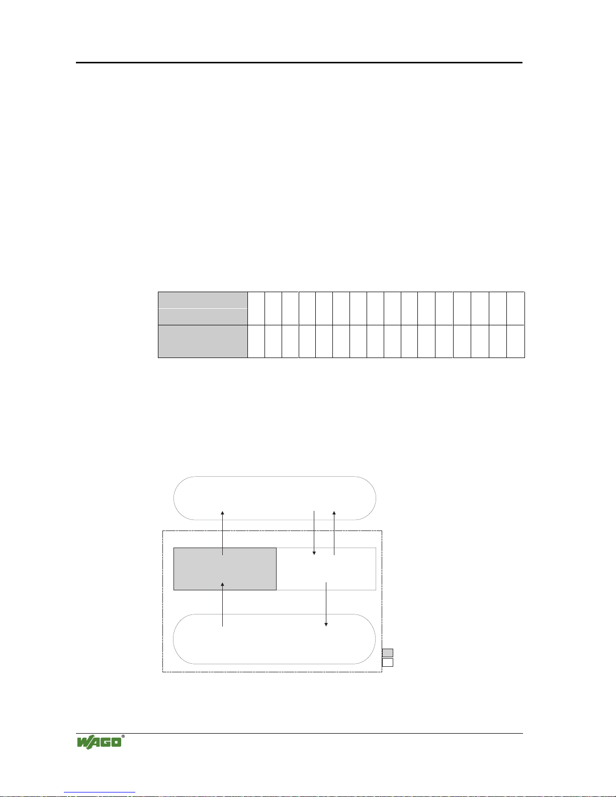
3.1.5.3 Data exchange between MODBUS master and I/O modules
The data exchange between the MODBUS master and the I/O modules is made by the implemented MODBUS functions in the coupler with reading and
writing in bits or bytes.
The controller handles four different types of process data:
• Input words
• Output words
• Input bits
• Output bits
The word for word access to the digital input and output modules is made in
accordance with the following table:
Digital inputs/
outputs
16. 15. 14. 13. 12. 11. 10. 9. 8. 7. 6. 5. 4. 3. 2. 1.
Process data
word
Bit15Bit14Bit13Bit12Bit11Bit10Bit9Bit8Bit7Bit6Bit5Bit4Bit3Bit2Bit1Bit
0
Table 3.3: Allocation of digital inputs/outputs to process data word acc. Intel format
The outputs can be read back by adding 0x0200 to the MODBUS address.
The register functions made available in the coupler, can be addressed by the
MODBUS master along with the implemented MODBUS function codes
(read/write). To this effect, the individual register address is entered in place of
the address of a module channel.
0x000
0x0FF
0x000
(0x200)
0x0FF
(0x2FF)
PII = Process Input
Image
PIO = Process Output
Image
MODBUS master
PII
PIO
I/O modules
Inputs
Outputs
Fieldbus Coupler
Fig. 3-10: Data exchange between the MODBUS master and I/O modules g012927e
Page 39

Fieldbus coupler 750-342 • 35
Starting up ETHERNET TCP/IP fieldbus nodes
Modular I/O System
ETHERNET TCP/IP
3.1.6 Starting up ETHERNET TCP/IP fieldbus nodes
This chapter shows the step-by-step procedure for starting up a
WAGO ETHERNET TCP/IP fieldbus node. The following also contains a description of how to read out the coupler-internal HTML pages.
Attention
This description is given as an example and is limited to the execution of a
local startup of an individual ETHERNET fieldbus node with a computer
running under windows which is not connected to a network.
Direct Internet connection should only be performed by an authorized network administrator and is, therefore, not described in this manual.
The procedure contains the following steps:
1. Noting the MAC-ID and establishing the fieldbus node
2. Connecting the PC and fieldbus node
3. Determining the IP address
4. Allocation of the IP address to the fieldbus node
5. Function of the fieldbus tests
6. Reading out information as HTML pages
3.1.6.1 Note the MAC-ID and establish the fieldbus node
Before establishing your fieldbus node, please note the hardware address
(MAC-ID) of your ETHERNET fieldbus coupler.
This is located on the rear of the fieldbus coupler and on the self-adhesive tearoff label on the side of the fieldbus coupler.
MAC-ID of the fieldbus coupler will be in this format:
----- ----- ----- ----- ----- -----.
3.1.6.2 Connecting PC and fieldbus node
Connect the assembled ETHERNET TCP/IP fieldbus node via a hub or directly to the PC using a 10Base-T cable.
Attention
For a direct connection, a crossover cable is required instead of a parallel cable.
Now start the PC, functioning as master and BootP server, and switch on the
voltage supply on the fieldbus coupler (DC 24 V power pack). Once the operating voltage has been switched on, the initialization starts. The fieldbus coupler determines the configuration of the bus modules and creates the process
image.
During the startup the ’I/O’ LED (Red) flashes at high frequency.
When the ’I/O’ LED and the ’ON’ LED light up green, the fieldbus coupler is
ready for operation.
If an error has occurred during startup, it is indicated as an error code by the
’I/O’-LED flashing (red).
Page 40

36 • Fieldbus coupler 750-342
Starting up ETHERNET TCP/IP fieldbus nodes
Modular I/O System
ETHERNET TCP/IP
3.1.6.3 Determining IP addresses
If your PC is already connected to an ETHERNET network, it is very easy to
determine the IP address of your PC. To do this, proceed as follows:
1. Go to the Start menu on your screen, menu item Settings and click on Con-
trol Panel.
2. Double click the icon Network.
The network dialog window will open.
3. - Under Windows NT: Select the register: Protocols and mark
the entry TCP/IP protocol.
- Under Windows 9x: Select the register: Configuration and mark
the entry TCP/IP network card.
Attention
If the entry is missing, please install the respective TCP/IP component and restart
your PC. The Windows-NT installation CD, or the installations CD for Windows
9x is required for the installation.
4. Subsequently, click the button "Properties...".
The IP address and the subnet mask are found in the ‘IP address’ tab.If applicable, the gateway address of your PC is found in the ‘Gateway’ tab.
5. Please write down the values:
IP address PC: ----- . ----- . ----- . ----Subnet mask: ----- . ----- . ----- . ----Gateway: ----- . ----- . ----- . -----
6. Now select a desired IP address for your fieldbus node.
Attention
When selecting your IP address, ensure that it is in the same local network in
which your PC is located.
7. Please note the IP address you have chosen:
IP address fieldbus node: ----- . ----- . ----- . -----
3.1.6.4 Allocating the IP address to the fieldbus node
The following describes how to allocate the IP address for the fieldbus node
using the WAGO BootP server by way of an example. You can download a
free copy from WAGO over the Internet under:
http://www.wago.com/wagoweb/usa/eng/support/downloads/index.htm.
Page 41

Fieldbus coupler 750-342 • 37
Starting up ETHERNET TCP/IP fieldbus nodes
Modular I/O System
ETHERNET TCP/IP
Note
The IP address can be allocated under other operating systems (i.e. under Linux) as well as with any other BootP servers.
Attention
The IP address can be allocated in a direct connection via a crossover cable or
via a parallel cable and a hub. An allocation over a switch is not possible.
BootP table
Note
Prerequisite for the following steps is the correct installation of the WAGO
BootP server.
1. Go to the Start menu, menu item Programs / WAGO Software / WAGO
BootP Server and click on WAGO BootP Server configuration.
An editable table will appear: "bootptab.txt".
This table displays the data basis for the BootP server. Directly following the
list of all notations used in the BootP table there are two examples for the
allocation of an IP address.
"Example of entry with no gateway" and "Example of entry with gateway".
Fig. 3-11: BootP table p012908e
The examples mentioned above contain the following information:
Declaration Meaning
node1,
node2
Any name can be given for the node here.
ht=1 Specify the hardware type of the network here.
The hardware type for ETHERNET is 1.
(The numbers are described in RFC1700)
ha=0030DE000100
ha=0030DE000200
Specify the hardware address or the MAC-ID of the ETHERNET
fieldbus coupler (hexadecimal).
ip= 10.1.254.100
ip= 10.1.254.200
Enter the IP address of the ETHERNET fieldbus coupler (decimal)
here.
T3=0A.01.FE.01 Specify the gateway IP address here.
Write the address in hexadecimal form.
sm=255.255.0.0 In addition enter the Subnet-mask of the subnet (decimal), where the
ETHERNET fieldbus coupler belongs to.
Page 42

38 • Fieldbus coupler 750-342
Starting up ETHERNET TCP/IP fieldbus nodes
Modular I/O System
ETHERNET TCP/IP
No gateway is required for the local network described in this example.
Therefore, the first example: "Example of entry with no gateway" can be
used.
2. Move the mouse pointer to the text line:
"node1:ht=1:ha=0030DE000100:ip=10.1.254.100" and mark the 12 character hardware address which is entered after ha=...
Enter the MAC-ID of your own network coupler.
3. If you want to give your fieldbus node a name, delete the name "node1" and
enter any name in its place.
4. To assign the coupler a desired IP address, mark the IP address specified in
the example which is entered after ip=...
Replace it with the IP address you have selected.
5. Because the second example is not necessary at present, insert a “#” in front
of the text line of the second example: "# node2:hat=1:ha=003 0DE 0002
00:ip=10.1.254.200:T3=0A.01.FE.01", so that this line will be ignored.
Note
To address more fieldbus nodes, enter a corresponding text line showing the
corresponding entries for each node.
6. Save the altered settings in this text file "bootptab.txt". To do this go to the
File menu, menu item Save, and close the editor.
BootP Server
7. Now open the dialog window for the WAGO BootP server by going to the
Start menu on your screen surface, menu item Program /
WAGO Software / WAGO BootP Server and click on WAGO BootP
Server.
8. Click on the "Start" button in the opened dialog window.
This will activate the inquiry/response mechanism of the BootP protocol.
A series of messages will be displayed in the BootP server. The error messages indicate that some services (i.e. port 67, port 68) in the operating system have not been defined.
Page 43

Fieldbus coupler 750-342 • 39
Starting up ETHERNET TCP/IP fieldbus nodes
Modular I/O System
ETHERNET TCP/IP
Fig. 3-12: Dialog window of the WAGO BootP server with messages g012909d
9. Now it is important to restart the coupler by resetting the hardware . This en-
sures that the new IP address will be accepted by the coupler.
To do this, cycle power to the fieldbus coupler for approx. 2 seconds.
Following this, the IP address in the coupler is permanently stored and
maintained even once the coupler is removed or following a longer voltage
failure.
10. Subsequently, click on the "Stop" button and then on the "Exit" button, to
close the BootP Server again.
3.1.6.5 Testing the function of the fieldbus node
1. To test the communication with the coupler and the correct assignment of
the IP address call up the DOS prompt under Start menu / Program / MS-
DOS Prompt.
2. Enter the command: "ping" with the IP address you have assigned in the
following form:
ping [space] XXXX . XXXX . XXXX . XXXX (=IP address).
Example: ping 10.1.254.202
Fig. 3-13: Example for the function test of a fieldbus node P012910e
3. When the Return key has been pressed, your PC will receive a response from
the coupler, which will then be displayed in the DOS prompt.
If the error message: "Timeout" appears instead, please compare your entries
again to the allocated IP address.
4. When the test has been performed successfully, you can close the DOS prompt.
The network node has now been prepared for communication.
Page 44
40 • Fieldbus coupler 750-342
Starting up ETHERNET TCP/IP fieldbus nodes
Modular I/O System
ETHERNET TCP/IP
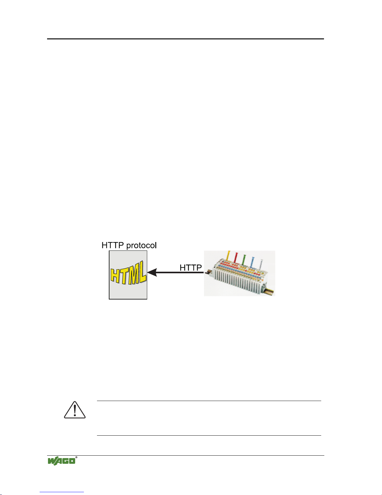
3.1.6.6 Reading out the information as HTML pages
The information saved in the fieldbus coupler can be read as an HTML page
using a web browser.
• Information on the fieldbus node (Terminal Status):
- Number of digital, analog or complex modules
- Representation of the process image
• Information on the fieldbus coupler (Coupler and Network Details):
- Order number
- Firmware version
- MAC-ID
- IP address
- Gateway address (if applicable)
- Subnet mask
- Number of transmitted and received packets
• Diagnostic information on the fieldbus coupler (Coupler Status):
- Error code
- Error argument
- Error description
Fig. 3-14: Reading out the information via the HTTP protocol G012916d
Please proceed as follows:
1. Open a web browser such as Microsoft Internet-Explorer, Netscape Navi-
gator, ...
2. Simply enter the IP address of your fieldbus node in the address field of the
browser and press the Return key.
The first HTML page with the information on your fieldbus coupler will be
displayed in the browser window. Use the hyperlinks to find out more information.
Attention
If the pages are not displayed after local access to the fieldbus node, then define in your web browser that, as an exception, no proxyserver is to be used for
the IP address of the node.
Page 45
Fieldbus coupler 750-342 • 41
LED Display
Modular I/O System
ETHERNET TCP/IP
3.1.7 LED Display
The coupler possesses several LED’s for displaying the coupler operating
status and the complete node status.
24V
0V
++
01 02
ON
LINK
TxD/RxD
I/O
ETHERNET
C
D
B
A
ERROR
status
voltage supply
-power jumper contacts
-system
Fig. 3-15: Display elements 750-342 G012901e
A differentiation is made between the two groups of LEDs.
The first group = fieldbus contains the solid color LEDs having the designa-
tion ON (green), LINK (green), TxD/RxD (green) and ERROR (red) indicating the operating status of the communication via ETHERNET.
The second group = internal bus consists of the three-color I/O LED
(red/green/orange). This LED is used to display the status of the internal bus
and i. e. the status of the fieldbus node.
LEDs located on the right-hand side in the coupler feed section, show the
status of the supply voltage.
3.1.7.1 Blink code
A blink code displays detailed fault messages. A fault is cyclically displayed
using up to 3 different blink sequences.
• The first blink sequence (approx. 10 Hz) indicates the fault display.
• After a pause a second blink sequence appears (approx. 1 Hz). The number
of blink impulses gives the fault code.
• The third blink sequence (approx. 1 Hz) appears following a further pause.
The number of blink pulses indicates the fault argument.
Page 46

42 • Fieldbus coupler 750-342
LED Display
Modular I/O System
ETHERNET TCP/IP
3.1.7.2 Fieldbus status
The operating status of the communication via ETHERNET is signalled by
means of the top LED group (ON, LINK, TxD/RxD and ERROR).
LED Meaning Trouble shooting
ON
green Fieldbus initialization is correct
OFF Fieldbus initialization is not correct,
no function or self-test
Check the supply voltage (24V and 0V),
check the IP configuration
LINK
green Link to a physical network exists
OFF No link to a physical network Check the fieldbus connection.
TxD/RxD
green Data exchange taking place
OFF No data exchange
ERROR
red Error on the fieldbus
OFF No error on the fieldbus, normal operation
3.1.7.3 Node status
The operating status of the communication via the internal bus is signalled via
the bottom I/O LED.
LED Meaning Trouble shooting
I/O
Green Fieldbus coupler operating perfectly
Red a) During startup of fieldbus coupler:
Internal bus being initialized,
Startup displayed by LED flashing fast for approx.
1-2 seconds
Red b) After startup of fieldbus coupler:
Errors, which occur, are indicated by three conse cutive flashing sequences. There is a short pause
between each sequential flash.
Evaluate the fault message (fault code and
fault argument).
The coupler starts up after switching on the supply voltage. The "I/O" LED
blinks. The "I/O" LED has a steady light following a fault free run-up.
In the case of a fault the "I/O" LED continues blinking. The fault is cyclically
displayed by the blink code.
Page 47
Fieldbus coupler 750-342 • 43
LED Display
Modular I/O System
ETHERNET TCP/IP
“I/O”-LED is blinking
Test o.k.?
No
Yes
“I/O”-LED is shining
ready for operation
2nd break
1st break
“I/O” LED
1st flash sequence
(Introduction of the
error indication)
“I/O” LED
2nd flash sequence
Error code
(Number of flash cycles)
“I/O” LED
3rd flash sequence
Error argument
(Number of flash cycles)
Coupler/Controller starts up
Switching on
the power supply
Fig. 3-16: Signalling of the LED for indication of the node status g012911e
After clearing a fault, restart the coupler by cycling the power.
3.1.7.4 Fault message via blink code from the I/O-LED
Fault argument Fault description
Fault code 1: Hardware and Configuration fault
0 EEPROM check sum fault / check sum fault in the parameter area of the flash memory
1 Overflow of the int ernal buffer memory for the inline code
2 Unknown data type
3 Module type of the flash program memory could not be determined / is incorrect
4 Fault when writing in the FLASH memory
5 Fault when deleting the FLASH memory
6 Changed I/O module configuration determined after AUTORESET
Fault code 2: Fault in programmed configuration
0 Incorrect table entry
Fault code 3: Internal bus command fault
0 No error argum ent is put out.
Page 48

44 • Fieldbus coupler 750-342
LED Display
Modular I/O System
ETHERNET TCP/IP
Fault code 4: Internal bus data fault
0 Data fault on internal bus or
Internal bus interruption on coupler
n* (n>0) Internal bus interrupted after I/O module n
Fault code 5: Fault duri ng register communication
n* Internal bus fault during register communication after I/O module n
Fault code 6: Fieldbus specific error
1 No reply from the BootP server
2 ETHERNET controller not recognized
3Invalid MACID
4 TCP/IP initialization error
Fault code 7: I/O module is not supported
n* I/O module at position n is not supported
Fault code 8: not used
0 Fault code 8 is not used.
Fault code 9: CPU-TRAP error
1 Illegal Opcode
2 Stack overflow
3 Stack underflow
4NMI
* The number of blink pulses (n) indicates the position of the I/O module. I/O modules
without data are not counted (i.e. supply modules without diagnostics).
Example for a fault message
Fault: The 13th I/O module has been removed.
1. The "I/O" LED starts the fault display with the first blink sequence (approx.
10 Hz).
2. The second blink phase (approx. 1 Hz) follows the first pause. The "I/O"
LED blinks four times and thus signals the fault code 4 (internal bus data
fault).
3. The third blink sequence follows the second pause. The "I/O ERR" LED
blinks twelve times. The fault argument 12 means that the internal bus is
interrupted after the 12
th
I/O module. Supply voltage status
There are two green LED’s in the coupler supply section to display the supply
voltage. The left LED (A) indicates the 24 V supply for the coupler. The right
hand LED (C) signals the supply to the field side, i.e. the power jumper contacts.
LED Meaning Trouble shooting
A
green Operating voltage for the system exists.
OFF No operating voltage for the system. Check the supply voltage (24V and 0V).
C
green Operating voltage for the power jumper contacts
exists.
OFF No operating voltage for the the power jumper con-
tacts.
Check the supply voltage (24V and 0V).
Page 49

Fieldbus coupler 750-342 • 45
Fault behavior
Modular I/O System
ETHERNET TCP/IP
3.1.8 Fault behavior
3.1.8.1 Fieldbus failure
A field bus failure is given i. e. when the master cuts-out or the bus cable is
interrupted. A fault in the master can also lead to a fieldbus failure.
A field bus failure is indicated when the red "ERROR"-LED is illuminated.
If the watchdog is activated, the fieldbus coupler firmware evaluates the
watchdog-register in the case of fault free communication, and the coupler answers all following MODBUS TCP/IP requests with the exception code
0x0004 (Slave Device Failure).
i
More information
For detailed information on the Watchdog register see Chaper 6.2.12
"Watchdog (Fieldbus failure)".
3.1.8.2 Internal bus fault
An internal bus fault is created, for example, if an I/O module is removed. If
this fault occurs during operation the output modules behave in the same manner as an I/O module stop. The "I/O" LED blinks red.
The coupler generates a fault message (fault code and fault argument).
After clearing the internal bus fault, restart the coupler by cycling the power.
The coupler starts up. The transfer of the process data is then resumed and the
node outputs are correspondingly set.
Page 50

46 • Fieldbus coupler 750-342
Technical Data
Modular I/O System
ETHERNET TCP/IP
3.1.9 Technical Data
System data
Max. n. of nodes limited by ETHERNET specification
Transmission medium
Twisted Pair S-UTP 100 Ω cat. 5
Buscoupler connection RJ45
Max. length of fieldbus segment
100 m between hub station and 750-342;
max. length of network limited by ETHERNET specification
Baud rate
10 Mbit/s
Protocols
MODBUS/TCP, HTTP, Bo otP
Approvals
UL E175199, UL508
Conformity marking Œ
Technical Data
Max. n. of I/O modules 64
Input process image max. 512 Byte
Output process image max. 512 Byte
max. n. of socket connections 1 HTTP, 3 MODBUS/TCP
Voltage supply DC 24 V (-15 % / + 20 %)
Input current
max
500 mA at 24 V
Efficiency of the power supply 87 %
Internal current consumption 200 mA at 5 V
Total current for I/O modules 1800 mA at 5 V
Isolation 500 V system/supply
Voltage via power jumper con-
tacts
max
DC 24 V (-15 % / + 20 %)
Current via power jumper contacts
max
DC 10 A
Dimensions (mm) B x H x T 51 x 65* x 100 (*from upper edge of DIN 35 rail)
Weight approx. 195 g
EMC Immunity to interference acc. to EN 50082-2 (95)
EMC Emission of interference acc. to EN 50081-2 (94)
Page 51

Fieldbus coupler /controller • 47
Fieldbus controller 750-842
Modular I/O System
ETHERNET TCP/IP
3.2 Fieldbus controller 750-842
This chapter includes:
3.2.1 Description .....................................................................................48
3.2.2 Hardware ........................................................................................49
1.1.1.1 View......................................................................................... 49
1.1.1.2 Device supply .......................................................................... 50
1.1.1.3 Fieldbus connection................................................................. 51
1.1.1.4 Display elements...................................................................... 51
1.1.1.5 Configuration and programming interface...............................52
1.1.1.6 Operating mode switch............................................................52
1.1.1.7 Hardware address (MAC-ID) .................................................. 53
3.2.3 Operating system............................................................................54
1.1.1.8 Start-up ....................................................................................54
1.1.1.9 PLC cycle.................................................................................54
3.2.4 Process image.................................................................................56
1.1.1.10 Example of a process input image........................................... 57
1.1.1.11 Example of a process output image......................................... 58
1.1.1.12 Process data architecture for MODBUS/TCP ......................... 59
3.2.5 Data exchange.................................................................................65
1.1.1.13 Memory areas .......................................................................... 66
1.1.1.14 Addressing ............................................................................... 67
1.1.1.15 Data exchange between master and I/O modules .................... 70
1.1.1.16 Data exchange between PLC functionality (CPU) and I/O
modules.................................................................................... 71
1.1.1.1 Data exchange between master and PLC functionality (CPU) 72
1.1.1.17 Common access of MODBUS master and PLC functionality to
outputs ..................................................................................... 73
3.2.6 Starting up ETHERNET TCP/IP fieldbus nodes............................75
1.1.1.18 Note the MAC-ID and establish the fieldbus node.................. 75
1.1.1.19 Connecting PC and fieldbus node............................................ 75
1.1.1.20 Determining IP addresses ........................................................76
1.1.1.21 Allocating the IP address to the fieldbus node ........................ 76
1.1.1.22 Testing the function of the fieldbus node ................................79
1.1.1.23 Viewing the HTML pages .......................................................80
3.2.7 Programming the PFC with WAGO-I/O-PRO 32.......................... 82
1.1.1.24 WAGO-I/O-PRO 32 library elements for ETHERNET.......... 82
1.1.1.25 IEC 61131-3-Program transfer ................................................84
3.2.8 LED Display................................................................................... 87
1.1.1.26 Blink code................................................................................87
1.1.1.27 Fieldbus status ......................................................................... 88
1.1.1.28 Node status............................................................................... 88
1.1.1.29 Fault message via blink code from the I/O-LED.....................90
1.1.1.30 Supply voltage status............................................................... 91
3.2.9 Fault behavior................................................................................. 92
1.1.1.31 Fieldbus failure ........................................................................ 92
1.1.1.32 Internal bus fault...................................................................... 92
3.2.10 Technical Data................................................................................93
Page 52

48 • Fieldbus controller 750-842
Description
Modular I/O System
ETHERNET TCP/IP
3.2.1 Description
The programmable fieldbus controller 750-842 (short: PFC) combines the
ETHERNET TCP/IP -functions of the fieldbus coupler 750-with that of a programmable logic control (PLC).
The application program is created with WAGO-I/O-PRO 32 in accordance
with IEC 61131-3.
All input signals of the sensors are grouped in the controller. According to the
IEC 61131-3 programming, process data treatment occurs locally in the PFC.
The link results created in this manner can be put out directly to the actuators
or transmitted to the higher ranking control system via the bus.
To be able to transmit process data via ETHERNET, the controller supports a
number of network protocols. The process data exchange is made with the aid
of the MODBUS/TCP protocol.
The programmer has the option to use function modules for programming clients and servers for all transport protocols (TCP, UDP, etc.) via a socket-API.
He has access to all fieldbus and I/O data.
Once the ETHERNET TCP/IP fieldbus controller is connected, it detects all
I/O modules connected to the node and produces a local process image on the
basis of the detected modules. This can be a mixed arrangement of analog
(word-by-word data exchange) and digital (bit-by-bit data exchange) modules.
The local process image is subdivided into an input and an output data area.
The data of the analog modules is mapped into the process image in the order
of their position after the bus coupler.
The bits of the digital modules are grouped to form words and also mapped
into the process image once mapping of the analog modules is completed.
Once the number of digital I/O’s exceeds 16 bits, the coupler automatically
starts another word.
Information on configuration, status and the I/O data of the fieldbus node are
stored in the fieldbus controller as HTML pages. These pages can be read via a
conventional WEB browser.
Page 53

Fieldbus controller 750-842 • 49
Hardware
Modular I/O System
ETHERNET TCP/IP
3.2.2 Hardware
3.2.2.1 View
24V
0V
++
-
-
01 02
750-842
ON
LINK
TxD/RxD
I/O
ETHERNET
C
D
B
A
ERROR
USR
0V
fieldbus
connection
RJ 45
configuration and
programming interface
status
voltage supply
-power jumper contacts
-system
data contacts
supply
24V
0V
supply via
power jumper contacts
24V
power jumper contacts
mode switch
flap
open
Fig. 3-17: Fieldbus controller ETHERNET TCP/IP g084200e
The fieldbus controller comprises of:
• Device supply with internal system supply module for the system supply as
well as power jumper contacts for the field supply via assembled I/O modules
• Fieldbus interface with the bus connection
• Display elements (LED’s) for status display of the operation, the bus com-
munication, the operating voltages as well as for fault messages and diagnosis
• Configuration and programming interface
• Operating mode switch
• Electronics for communication with the I/O modules (internal bus) and the
fieldbus interface
Page 54
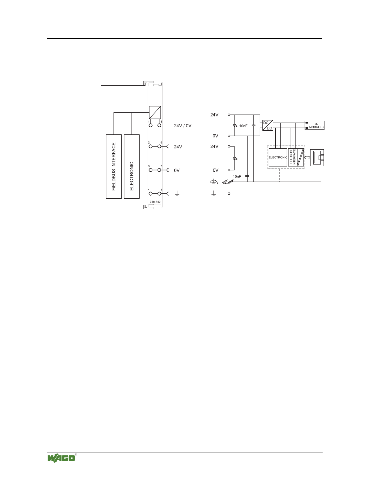
50 • Fieldbus controller 750-842
Hardware
Modular I/O System
ETHERNET TCP/IP
3.2.2.2 Device supply
The supply is via fed in via terminal blocks with CAGE CLAMP
®
connection.
Device supply is intended for system supply and field side supply.
Fig. 3-18: Device supply G034201e
The integrated internal system supply module generates the necessary voltage
to supply the electronics and the connected I/O modules.
The fieldbus interface is supplied with electrically isolated voltage from the
internal system supply module.
Page 55
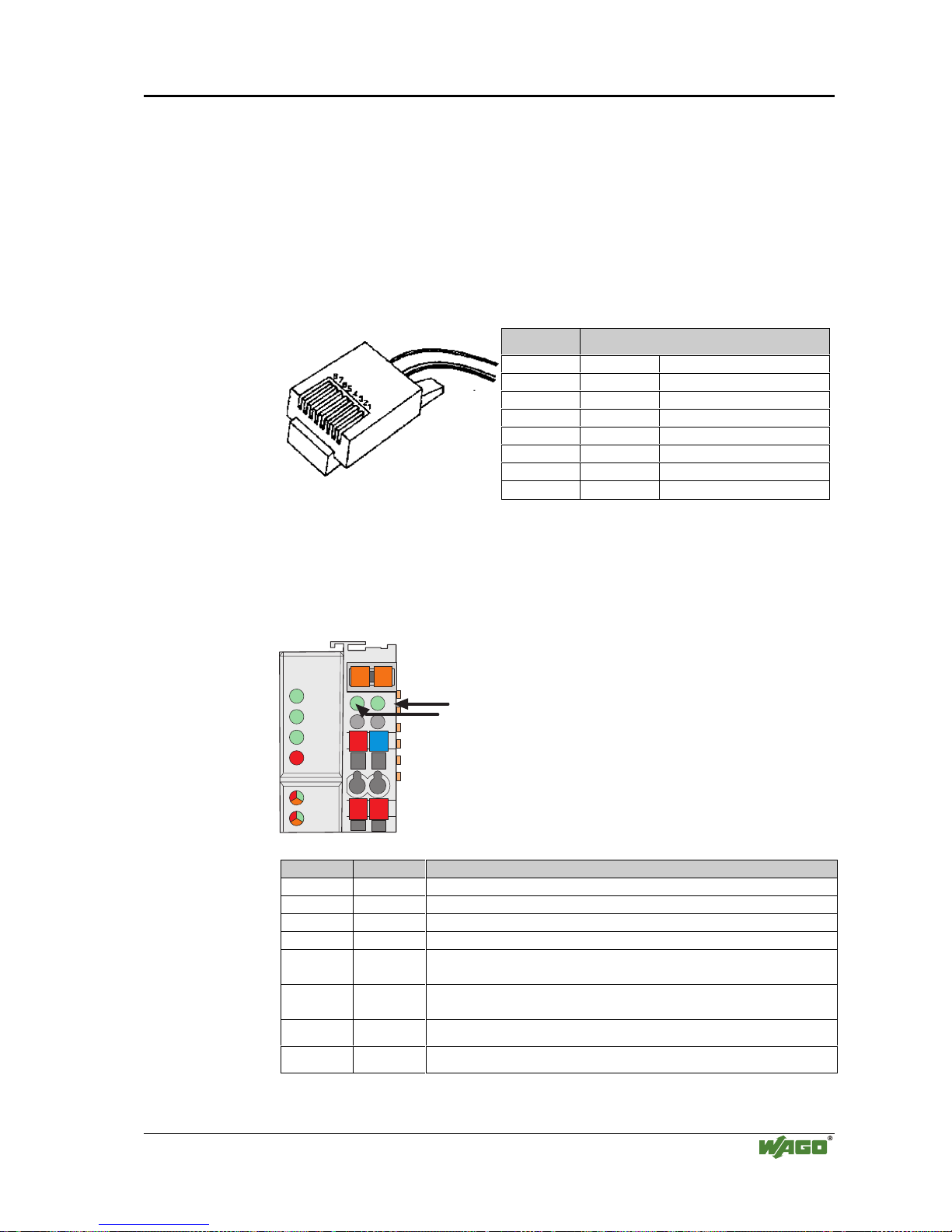
Fieldbus controller 750-842 • 51
Hardware
Modular I/O System
ETHERNET TCP/IP
3.2.2.3 Fieldbus connection
Connection to the fieldbus is by a RJ45 connector. A category 5,
shielded/unshielded twisted pair cable (S-UTP) with an impedance of 100
Ohm ±15% is mandatory as a connecting line for the 10BaseT Interface.
The connection point is physically lowered for the coupler/controller to fit in
an 80 mm high switch box once connected.
The electrical isolation between the fieldbus system and the electronics is
achieved by means of DC/DC converters and optocouplers in the fieldbus interface.
Contact Signal
1 TD + Transmit +
2 TD - Transmit 3 RD + Receive +
4free
5free
6 RD - Receive 7free
8free
Fig. 3-19: RJ45-connector and RJ45 connector configuration
3.2.2.4 Display elements
The operating condition of the fieldbus controller or node is displayed via light
diodes (LED).
24V
0V
++
01 02
ON
LINK
TxD/RxD
I/O
ETHERNET
C
D
B
A
ERROR
USR
status
voltage supply
-power jumper contacts
-system
Fig. 3-20: Display elements 750-842 G012902e
LED Color Meaning
ON green Fieldbus initialization is correct
LINK green Link to a physical network exists
TxD/RxD green Data exchange taking place
ERROR red Error on the fieldbus
IO red /green
/ orange
The ’I/O’-LED indicates the operation of the node and signals faults
encountered
USR red /green
/ orange
The ’USR’ LED can be selected by a user program in a programmable fieldbus controller
A green Status of the operating voltage – system
C green Status of the operating voltage – power jumper contacts
Page 56

52 • Fieldbus controller 750-842
Hardware
Modular I/O System
ETHERNET TCP/IP
3.2.2.5 Configuration and programming interface
The configuration and programming interface is located behind the cover flap.
This is used to communicate with WAGO-I/O-CHECK and
WAGO-I/O-PRO 32 as well as for firmware downloading.
Configuration and
programming interface
open
flap
Fig. 3-21: Configur ation interface g01xx06e
The communication cable (750-920) is connected to the 4 pole male header.
3.2.2.6 Operating mode switch
The operating mode switch is located behind the cover flap.
Update firmware
Run
Stop
Reset
(pushing down)
open
flap
mode switch
Fig. 3-22: Operating mode switch g01xx10e
The switch is a push/slide switch with 3 settings and a hold-to-run function.
Operating mode switch Function
From middle to top position Activate program processing (RUN)
From top to middle position Sto p program processing (STOP)
Lower position, bootstrap For original loading of firmware,
not necessary for user
Push down
(i.e. with a screwdriver)
Hardware reset
All outputs and flags are reset; variables are set to 0 or to
FALSE or to an initial value.
The hardware reset can be performed with STOP as well
as RUN in any position of the operating mode switch!
Page 57

Fieldbus controller 750-842 • 53
Hardware
Modular I/O System
ETHERNET TCP/IP
An operating mode is internally changed at the end of a PLC cycle.
Attention
If outputs are set when switching from RUN to STOP mode, they remain set!
Switching off the outputs on the software side i.e. by the initiators are ineffective because the program is no longer processed.
Note
With "GET_STOP_VALUE" (library "System.lib") WAGO-I/O-PRO 32 provides a function which recognizes the last cycle prior to a program stop giving the user the possibility to program the behavior of the controller in case of
a STOP. With the aid of this function the controller outputs can be switched
to a safe condition.
3.2.2.7 Hardware address (MAC-ID)
Each WAGO ETHERNET TCP/IP fieldbus controller is provided from the
factory with a unique and internationally unambiguous physical ETHERNET
address, also referred to as MAC-ID (Media Access Control Identity). This is
located on the rear of the controller and on a self-adhesive tear-off label on the
controller side. The address has a fixed length of 6 Bytes (48 Bit) and contains
the address type, the manufacturer’s ID, and the serial number.
Page 58

54 • Fieldbus controller 750-842
Operating system
Modular I/O System
ETHERNET TCP/IP
3.2.3 Operating system
3.2.3.1 Start-up
The controller starts-up after switching on the supply voltage or after a hardware reset. The PLC program in the flash memory is transferred to the RAM.
This is followed by the initialization of the system. The controller determines
the I/O modules and the present configuration. The variables are set to 0 or to
FALSE or to an initial value given by the PLC program. The flags retain their
status . The "I/O" LED blinks red during this phase.
Following a fault free start-up the controller changes over to the "RUN" mode.
The "I/O" LED lights up green.
There is not a PLC program in the flash memory when delivered. The controller start-up as described, without initialiing the system. Then it behaves as a
coupler
3.2.3.2 PLC cycle
The PLC cycle starts following a fault free start-up when the operating mode
switch is in the top position or by a start command from the
WAGO-I/O-PRO 32. The input and output data of the fieldbus and the I/O
modules as well as the times are read. Subsequently, the PLC program in the
RAM is processed followed by the output data of the fieldbus and the I/O
modules in the process image. Operating system functions, amongst others, for
diagnostics and communications are performed and the times calculated at the
end of the PLC cycle. The cycle starts again with the reading of the input and
output data and the times.
The change of the operating mode (STOP/RUN) is made at the end of a PLC
cycle.
The cycle time is the time from the start of the PLC program to the next start.
If a loop is programmed within a PLC program, the PLC running time and thus
the PLC cycle are extended correspondingly.
The inputs, outputs and times are not updated during the processing of the
PLC program. This calculation occurs in a defined manner only at the end of
the PLC program. For this reason it is not possible to wait for an event from
the process or the elapse of a time within a loop.
Page 59

Fieldbus controller 750-842 • 55
Operating system
Modular I/O System
ETHERNET TCP/IP
Variables are set to 0 or FALSE
or to their initial value,
flags remain in the same status.
Switching on the
supply voltage
Initialization
of the system
Reading inputs, outputs and times
Writing outputs
Fieldbus data,
data of I/O modules
Operating system functions,
updating times
Is a PLC
program in the Flash
memory ?
No
Yes
PLC program transfer
from the flash memory to RAM
Determination of the I/O modules
and the configuration
Test o.k.?
Yes
No
Stop
Test o.k.?
No
Determination of the I/O modules
and the configuration
STOP
Operating mode
Operating mode
STOP
RUN
RUN
Fieldbus data,
data of I/O modules
Yes
Fieldbus start
behaviour as a coupler
operating mode switch
is in the top position or
start command in
WAGO-IO- 32:
or
PRO
Online/Start Online/Stop
operating mode switch
is in the top position or
start command in
WAGO-IO- 32:
or
PRO
Online/Start Online/Stop
“I/O” LED
is blinking
orange
“I/O” LED
is blinking
red
PLC cycle
“I/O” LED
is shining
green
PLC program in the RAM
is processed
Fig. 3-23: Controller operating system g012941e
Page 60

56 • Fieldbus controller 750-842
Process image
Modular I/O System
ETHERNET TCP/IP
3.2.4 Process image
The powered up controller recognizes all I/O modules connected in the node,
which are waiting for or transmitting data (data width/bit width > 0). In nodes
analog and digital I/O modules can be intermixed.
Note
For the number of input and output bits or bytes of the individual switched on
I/O modules please refer to the corresponding description of the I/O modules.
The controller generates an internal local process image from the data width
and the type of I/O module as well as the position of the I/O modules in the
node. This is divided into an input and an output area.
The data of the digital I/O modules are bit orientated, i.e. the data exchange is
made bit by bit. The analog I/O modules are representative for all I/O modules
which are byte orientated, in which the data exchange is also made byte by
byte. These I/O modules also include, for example, counter modules, I/O modules for angle and path measurement as well as communication modules.
The data of the I/O modules is separated for the local input and output process
image in the sequence of their position after the controller in the individual
process image.
First, all the byte-oriented bus modules are filed in the process image, then the
bit-oriented bus modules. The bits of the digital modules are grouped into
bytes. Once the number of digital I/O’s exceeds 8 bit, the coupler automatically starts another byte.
Note
If a node is changed, this may result in a new process image structure. In this
case the process data addresses also changes. In the event of adding modules,
the process data of all previous modules has to be taken into account.
The process image for the physical bus module data is identical with that of
the WAGO ETHERNET TCP/IP fieldbus coupler. The controller uses a memory space of 256 words (word 0 ... 255) for the phyical input and output data.
The controller is assigned an additional memory space for imaging the PFC
variables defined according to IEC 61131-3. This extended memory space
(word 256 ... 511 each) is used to map the PFC variables behind the physical
process image.
The division of the memory spaces and the access of the PLC functionality
(CPU) to the process data is identical with all WAGO fieldbus controllers. Access is via an application related IEC 61131-3 program and independent on the
fieldbus system.
In contrast to the above, access from the fieldbus side is fieldbus specific.
For the ETHERNET TCP/IP fieldbus controller, a MODBUS/TCP master can
access the data via implemented MODBUS functions. Here, decimal and/or
hexadecimal MODBUS addresses are used.
Page 61
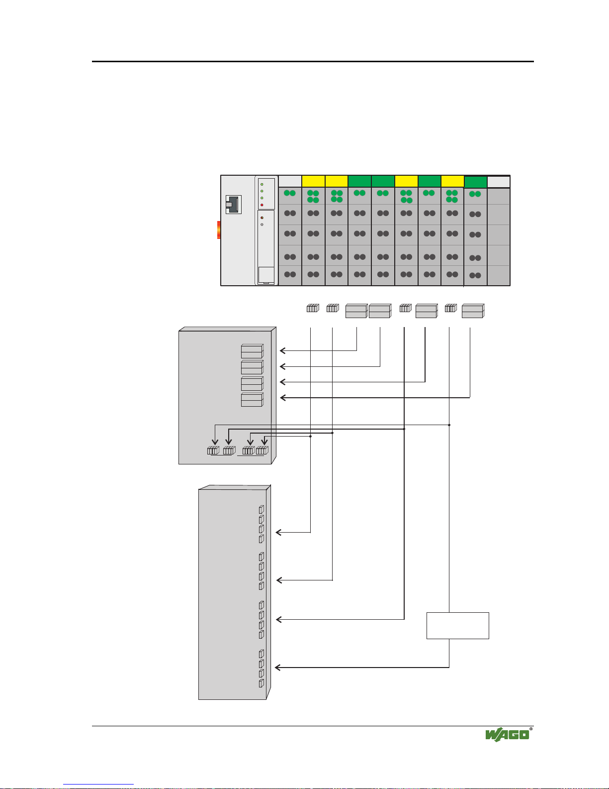
Fieldbus controller 750-842 • 57
Example of process input image
Modular I/O System
ETHERNET TCP/IP
3.2.4.1 Example of a process input image
The following figure is an example of a process input image.
The configuration comprises of 16 digital and 8 analog inputs.
The process image thus has a data length of 8 words for the analog and 1 word
for the digital inputs, i.e. 9 words in total.
Bit 1
Bit 4
Word2
Word1
Word2
Word1
Word2
Word1
Word2
Word1
Word2
Word1
Word2
Word1
1
4
1411
4
1
ON
LINK
TxD/RxD
ERROR
Ethernet
750-842
I/O
WAGO
ßI/O
ßSYSTEM
DI
DI
DI
DI
AI
AI
AI
AI
Word2
Word1
Word2Word2
Word1
Highbyte
Lowbyte
0x0003 %IW3
0x0002 %IW2
0x0001 %IW1
0x0000 %IW0
0x0005 %IW5
0x0004 %IW4
0x0007 %IW7
0x0006 %IW6
0x0008 %IW8
0x0001 %IX8.1
0x0000 %IX8.0
0x0003 %IX8.3
0x0002 %IX8.2
0x0004 %IX8.40x0004 %IX8.4
0x0008 %IX8.8
0x000C %IX8.12
0x0005 %IX8.50x0005 %IX8.5
0x0009 %IX8.9
0x000D %IX8.13
0x0006 %IX8.60x0006 %IX8.6
0x000A %IX8.10
0x000E %IX8.14
0x0007 %IX8.70x0007 %IX8.7
0x000B %IX8.11
0x000F %IX8.15
Process input image
(Word)
addresses
Process input image
(Bit)
Input modules 750- 402 402 472 472 402 476 402 476
DI: Digital Input
AI:Analog Input
addresses
MODBUS PFC
MODBUS PFC
Fig. 3-24: Example of a process input image G012924e
Page 62

58 • Fieldbus controller 750-842
Example of process output image
Modular I/O System
ETHERNET TCP/IP
3.2.4.2 Example of a process output image
The following example for the process output image comprises of 2 digital and
4 analog outputs.
It comprises of 4 words for the analog and 1 word for the digital outputs, , i.e.
5 words in total.
In addition, output data can be read back with an offset of 200
hex
(0x0200)
added to the MODBUS address.
Bit 1
Bit 2
Word2
Word1
Word2
Word1
Word2
Word1
Word2
Word1
Word2
Word1
Word2
Word1
0x0003 / 0x0203 %QW3
0x0002 / 0x0202 %QW2
0x0001 / 0x0201 %QW1
0x0000 / 0x0200 %QW0
0x0004 / 0x0204 %QW4
0x0203 %QW3
0x0202 %QW2
0x0201 %QW1
0x0200 %QW0
0x0204 %QW4
0x0000 / 0x0200 %QX4.0
0x0001 / 0x0201 %QX4.1
0x0200 %QX4.0
0x0201 %QX4.1
ON
LINK
TxD/RxD
ERROR
Ethernet
750-842
WAGO
ßI/O
ßSYSTEM
AO
DO
AO
Highbyte
Lowbyte
Highbyte
Lowbyte
MODBUS addresses
MODBUS addresses
MODBUS addresses
MODBUS addresses
Process output image
(Word)
Process input image
(Word)
Process output image
(Bit)
Process input image
(Bit)
DO: Digital Output
AO: Analog Output
Output modules 750 - 501 550 550
Fig. 3-25: Example of a process output image G012925e
Page 63

Fieldbus controller 750-842 • 59
Process data architecture for MODBUS/TCP
Modular I/O System
ETHERNET TCP/IP
3.2.4.3 Process data architecture for MODBUS/TCP
For some bus modules or their variations, the process data architecture is specific for the fieldbus controller used.
In the case of the ETHERNET controller with MODBUS/TCP the control/status byte is always masked in addition to the data bytes. This is required
for the two-directional data exchange of the bus module with the higherranking control system. The control byte is transmitted from the control system
to the module and the status byte from the module to the control system. This
allows, for example, the display of overshooting or undershooting of the area.
Attention
Please refer to the respective bus module description in Chapter 4 "I/O modules" for the specific architecture of the respective control/status byte.
The following shows the representation of some selected modules in the process image.
In the examples, the order in which the modules are physically arranged in the
node reflects the order in the image table starting with register address 0x0000.
If the module is located at any other position in the fieldbus node, the process
data of all previous byte-wise oriented modules have to be taken into account.
In the process image, this results in a basic register address for the module. To
address its process data words, the quoted offset is added to this basic address.
If an analog input or output module is added, it takes up 2 x 16 Bit input or
output data.
With the ETHERNET fieldbus controller with MODBUS/TCP the process image is organized word-by-word (word-alignment) and the control/status byte is
always a low byte.
Page 64
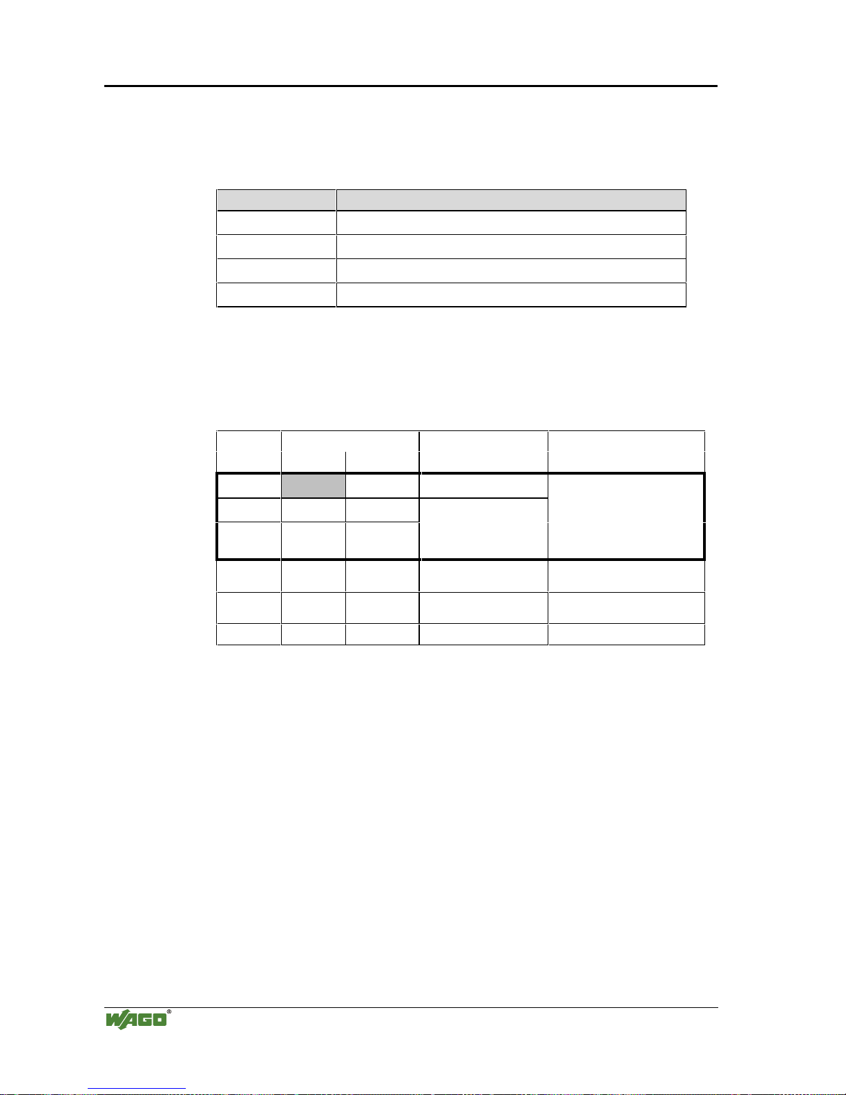
60 • Fieldbus controller 750-842
Process data architecture for MODBUS/TCP
Modular I/O System
ETHERNET TCP/IP
3.2.4.3.1 750-404, /000-00X Counter modules
This process data architecture holds true for the counter modules 750-404,
750-404/000-001, 750-404/000-002 and 750–404/000-004.
Item number: Description:
750-404 Up/Down Counter
750-404/000-001 2 Channel Up Counter with enable input
750-404/000-002 Peak Time Counter
750-404/000-004 Up/Down Counter (switching outputs)
The data format of the counter modules five bytes is mapped out by the module as four data bytes and one additional control/status byte. The module
supplies a 32 bit counter-output, while occupying 3 words each in the process
image with word-alignment.
Address Bytes Comment Module
Offset High Low
0 C/S Control-/ Status byte
1D1D0
2D3D2
Data bytes
Module 1:
750-404,
750-404/000-001,
750-404/000-002,
750-404/000-004
3 User data User data Data bytes
Module 2:
Analog module Channel 1
4 User data User data Data bytes
Module 2:
Analog module Channel 2
... ... ... ... ...
The input bytes D0 to D3 form the 32 bit counter-output.
In the output bytes D0 to D3 the initial value of the counter can be set.
Page 65
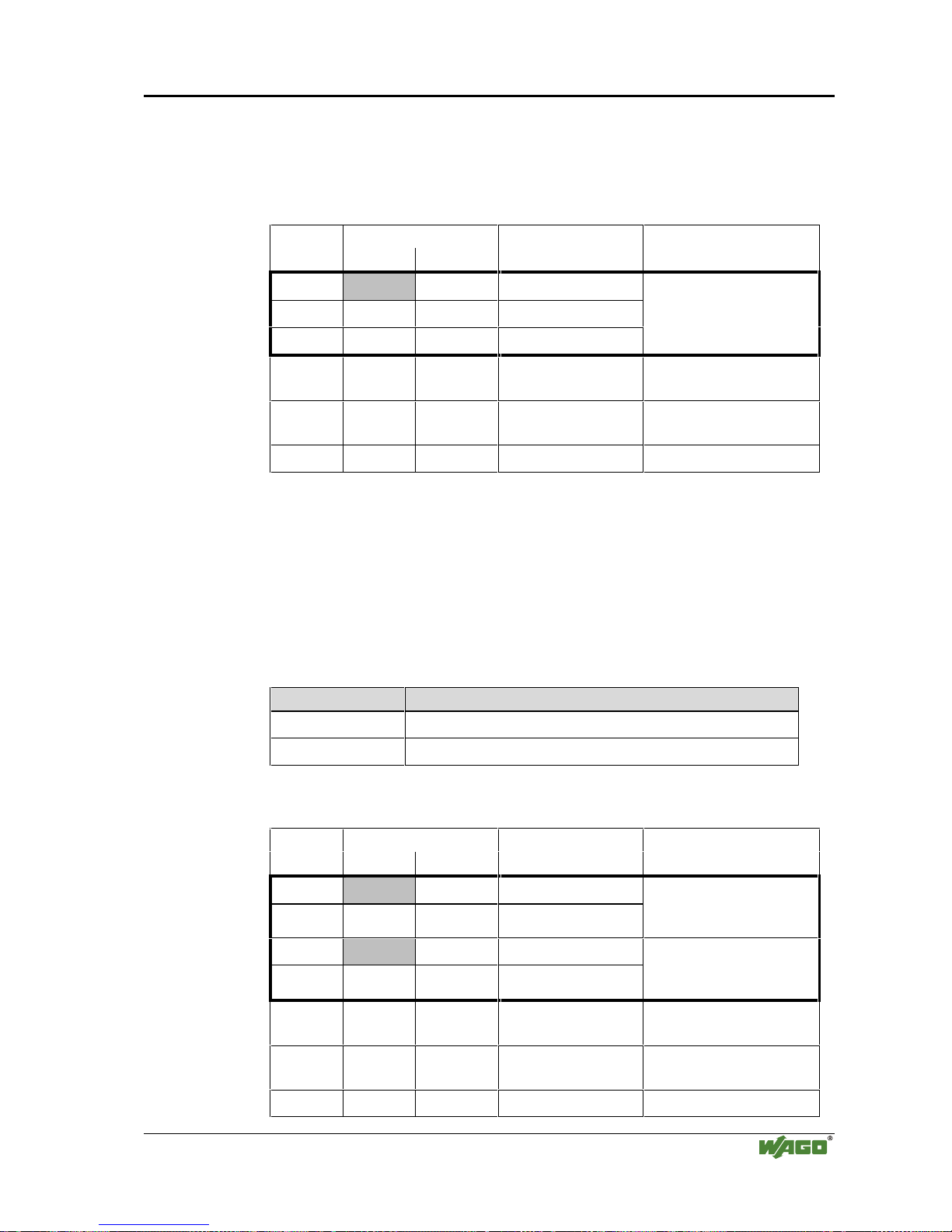
Fieldbus controller 750-842 • 61
Process data architecture for MODBUS/TCP
Modular I/O System
ETHERNET TCP/IP
3.2.4.3.2 750-404/000-005 2 Channel Up Counter 16 Bit
The data format of the counter modules five bytes is mapped out by the module as four data bytes and one additional control/status byte, while occupying
3 words each with word-alignment.
Address Bytes Comment Module
Offset High Low
0 C/S Control/ Statusbyte
1 D1 D0 Data bytes Counter 1
2 D3 D2 Data bytes Counter 2
Module 1:
750-404/000-005
3 User data User data Data bytes
Module 2:
Analog module Channel 1
4 User data User data Data bytes
Module 2:
Analog module Channel 2
... ... ... ... ...
The input bytes D0 and D1 form the 16 bit reading of counter 1 and the input
bytes D2 and D3 form the 16 bit reading of counter 2.
When setting the counter, the load value of counter 1 is transferred in the output bytes D0 and D1. The load value of counter 2 is transferred respectively in
the output bytes D2 and D3.
3.2.4.3.3 750-511, /000-002 2-Channel Digital Pulsewidth module
This process data architecture holds true for the 2 Channel Pulsewidth modules 750-511 and 750–511/000-002.
Item-No.: Description:
750-511 2DO 24V DC 0.1A Pulsewidth
750-511/000-002 2DO 24V DC 0,1A Pulsewidth 100Hz
The process image of the 750-511 and 750-511/000-002 appears with 6 bytes
of input and 6 bytes of output data, while occupying 4 words each in the process image with word-alignment.
Address Bytes Comment Module
Offset High Low
0 C/S-0 Control / Status byte
1 D1-0 D0-0
Data bytes
Module 1 Channel 1:
750-511,
750-511/000-002
2 C/S-1 Control / Status byte
3 D1-1 D0-1 Data bytes
Module 1 Channel 2:
750-511,
750-511/000-002
4 User data User data Data bytes
Module 2:
Analog Module Channel 1
5 User data User data Data bytes
Module 2:
Analog Module Channel 2
... ... ... ... ...
Page 66

62 • Fieldbus controller 750-842
Process data architecture for MODBUS/TCP
Modular I/O System
ETHERNET TCP/IP
3.2.4.3.4 750-630, /000-00X SSI encoder interface 24 Bit
This process data architecture holds true for the SSI encoder interface modules
750-630, 750-630/000-001 and 750–630/000-006.
Item-No.: Description:
750-630 SSI encoder interface 24Bit, 125kHz Gray code, alternative Data
format
750-630/000-001 SSI encoder interface 24Bit, 125kHz Binary code, alternative
Data format
750-630/000-006 SSI encoder interface 24Bit, 250kHz Gray code, alternative Data
format
The module is seen like an analog input with 2 x 16 Bit input data, i.e. with a
total of 4 bytes user data. Here 2 words in the input area of the local process
image are occupied with word-alignment.
Address Bytes Comment Module
Offset High Low
0D1D0
1D3D2
Data bytes
Module 1:
750-630,
750-630/000-001,
750-630/000-006
2 User data User data Data bytes
Module 2:
Analog module Channel 1
3 User data User data Data bytes
Module 2:
Analog module Channel 2
... ... ... ... ...
3.2.4.3.5 750-631, /000-001 Incremental Encoder Interface
This process data architecture holds true for the Incremental Encoder Interface
modules 750-631 and 750–631/000-001.
Item-No.: Description:
750-631 Incremental encoder interface, 4 times sampling
750-631/000-001 Incremental encoder interface, 1 times sampling
The bus module 750-631 and 750-631/000-001 002 appears with 6 bytes of
input and 6 bytes of output data and occupies 4 words each with word-alignment.
Page 67

Fieldbus controller 750-842 • 63
Process data architecture for MODBUS/TCP
Modular I/O System
ETHERNET TCP/IP
Address Bytes Comment Module
Offset High Low
0 C/S Control / Status byte
1 D1 D0 ead/set counter word
3 (D2)*
)
(period)
4 D4 D3 read latch word
Module 1:
750-631,
750-631/000-001
5 User data User data Data bytes
Module 2:
Analog module Channel 1
6 User data User data Data bytes
Module 2:
Analog module Channel 2
... ... ... ... ...
The control / status byte is in the low byte on offset 0.
The data word D0/D1 contains the counter word (read/set), whereas the data
word D3/D4 contains the latch word (read).
*) In the operating mode of permanent period measurement, the period duration is in D2 together with D3/D4.
3.2.4.3.6 750-650 RS232 Interface module,
750-651 TTY-,20 mA Current Loop,
750-653 RS485 Interface module
This process data architecture holds true for the modules 750-650, 750-651
and 750–653.
Item-No.: Description:
750-650 RS 232 C Interface 9600,n,8,1
750-651 TTY Interface, 20 mA Current Loop
750-653 RS485 Interface
The modules appear on the bus as a combined analog input and output module
with 3 x 16-bit input and output data, i.e. with a total of 4 bytes user data. Here
2 words each are occupied with word-alignment.
Address Bytes Comment Module
Offset High Low
0D0C/S
Data
byte
Control /
Status byte
1D2D1
Data bytes
Module 1:
750-650,
750-651,
750-653
2 User data User data Data bytes
Module 2:
Analog module Channel 1
3 User data User data Data bytes
Module 2:
Analog module Channel 2
... ... ... ... ...
Page 68
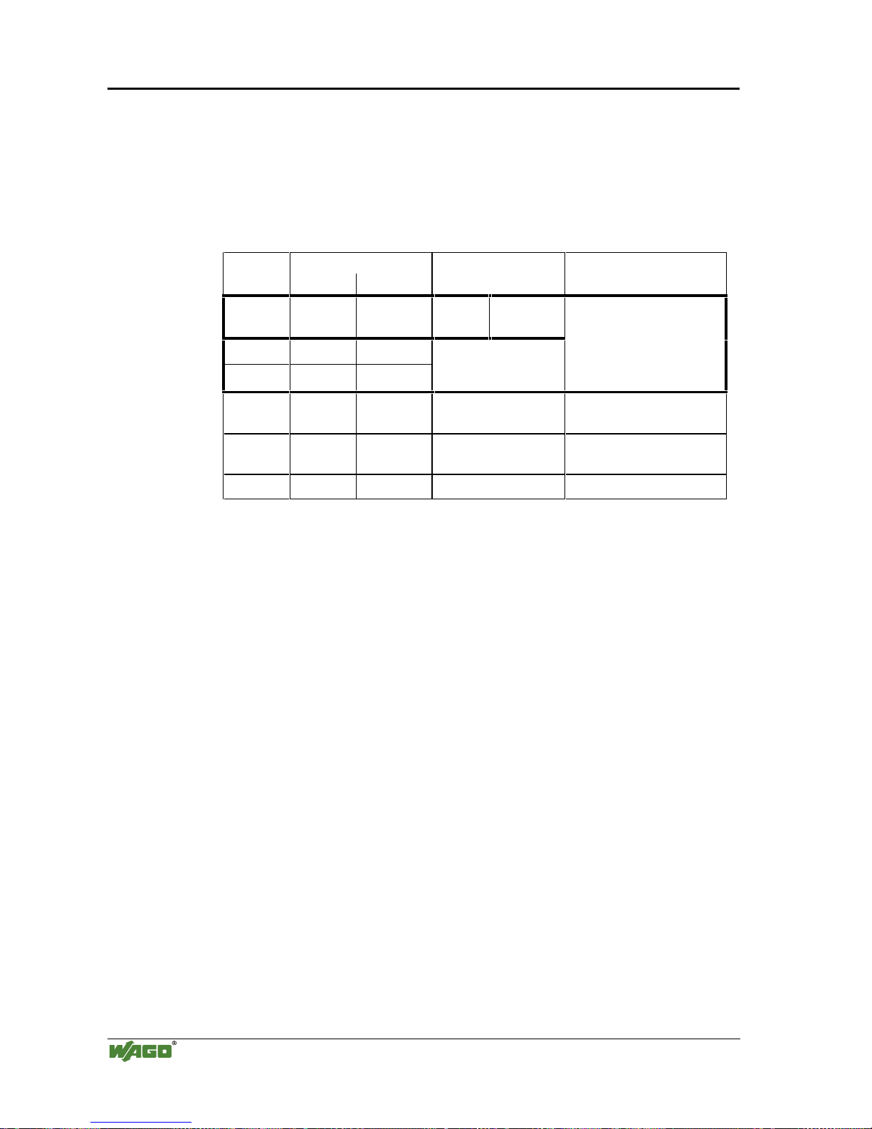
64 • Fieldbus controller 750-842
Process data architecture for MODBUS/TCP
Modular I/O System
ETHERNET TCP/IP
3.2.4.3.7 750-650/000-001 RS232 Interface module 5 Byte
The RS232 interface module 750-650 can also be operated with a data format
of 5 bytes and one Control/Status byte, i.e. a total of 6 bytes user data. For this
data format, order the variation with the part number 750-650/000-001, occupying 3 words each in the input and output area of the process image with
word-alignment.
Address Bytes Comment Module
Offset High Low
0D0C/S
Data
byte
Control /
Status byte
1D2D1
2D4D3
Data bytes
Module 1:
750-650/000-001
3 User data User data Data bytes
Module 2:
Analog module channel 1
4 User data User data Data bytes
Module 2:
Analog module channel 2
... ... ... ... ...
Page 69

Fieldbus controller 750-842 • 65
Data exchange
Modular I/O System
ETHERNET TCP/IP
3.2.5 Data exchange
With the ETHERNET TCP/IP fieldbus controller data is exchanged via the
MODBUS/TCP protocol.
MODBUS/TCP works according to the master/slave principle. The master is a
superimposed control unit, i.e. a PC or a PLC device.
The ETHERNET TCP/IP controller of the WAGO-I/O-SYSTEM 750nor-
mally are slave devices. Due to the programming with IEC 61131-3, controllers can additionally assume the master function.
The master makes a query for communication. By adressing this query can be
sent to a specific node. The nodes receive the query and return a response to
the master, depending on the kind of query.
A coupler is able to produce a certain number of simultaneous connections
(socket connections) to other network subscribers:
• 1 connection for HTTP (read HTML pages from the controller),
• 3 connections via MODBUS/TCP (read or write input and output data from
the controller),
• 2 connections via the PFC (available in the PLC functionality for IEC
61131-3 application programs) and
• 2 connections for WAGO-I/O-PRO (these connections are reserved for de-
bugging the application program via ETHERNET.
For debugging, WAGO-I/O-PRO requires 2 connections at the same time.
However, only one programming tool can have access to the controller.
The maximum number of simultaneous connections may not be exceeded. If
you wish to establish further connections, terminate existing connections first.
For a data exchange, the ETHERNET TCP/IP fieldbus controller uses three
main interfaces:
• interface to the fieldbus (master),
• the PLC functionality of the PFCs (CPU) and
• the interface to the bus terminals.
Data exchange takes place between the MODBUS master and the bus modules,
between the PLC functionality of the PFCs (CPU) and the bus modules as well
as between the MODBUS master and the PLC functionality of the PFCs (CPU).
The master accesses the data via the MODBUS functions implemented in the
controller.
PFC access to data is then made by means of an IEC 61131-3 application program, whereby data addressing is different.
Page 70

66 • Fieldbus controller 750-842
Data exchange
Modular I/O System
ETHERNET TCP/IP
3.2.5.1 Memory areas
CPU
I
O
1
3
2
4
1
3
2
4
Programmable Fieldbus Controller
memory area
for input data
word 0
word 255
word 256
input
modules
PFC
input
variables
IEC 61131program
word 511
memory area
for output data
output
modules
word 0
word 255
word 256
word 511
PFC
output
variables
fieldbus
master
I/O modules
Fig. 3-26: Memory areas and data exchange for a fieldbus controller g012938e
In the memory space word 0 ... 255, the controller process image contains the
physical data of the bus modules.
(1) The data of the input modules can be read by the CPU and from the field-
bus side.
(2) In the same manner, writing on the output modules is possible from the
CPU and from the fieldbus side. The value of the master is put out on the
output while writing on an output.
The PFC variables are filed in the memory space Word 256 ... 511 of the process image.
The PFC input variables are written in the input memory space from the fieldbus side and read by the CPU for further processing.
The variables processed by the CPU via the IEC 61131-3 program are filed in
the output memory space and can be read out by the master.
In addition, with the ETHERNET TCP/IP controller all output data are mirror
imaged on a memory space with the address offset 0x0200 which allows to
read back output values by adding 0x0200 to the MODBUS address.
Page 71

Fieldbus controller 750-842 • 67
Data exchange
Modular I/O System
ETHERNET TCP/IP
In addition, the controller offers further memory spaces which cannot be accessed from the fieldbus side:
RAM The RAM memory is used to create variables not required for
communication with the interfaces but for internal processing,
such as for instance computation of results.
The retentive memory is non volatile memory, i.e. all values are
retained following a voltage failure. The memory management is
automatic. In this memory area, flags for the IEC 61131-3 program are filed together with variables without memory space
addressing or variables which are explicitly defined with "var
retain".
Retentive
memory
Note
The automatic memory management can cause a data
overlap. For this reason, we recommend not to use a
mix of flags and retain variables.
Code
memory
The IEC 61131-3 program is filed in the code memory. The code
memory is a flash ROM. Once the supply voltage is applied, the
program is transmitted from the flash to the RAM memory. After
a successful start-up, the PFC cycle starts when the operating
mode switch is turned to its upper position or by a start command from WAGO-I/O-PRO 32.
3.2.5.2 Addressing
3.2.5.2.1 Addressing the I/O modules
The arrangement of the I/O modules in a node is optional.
When addressing, first of all the complex modules (modules occupying 1 or
more bytes) are taken into consideration in accordance with their physical order
behind the fieldbus controller. As such, they occupy the addresses beginning
with word 0.
Following this, the data of the other modules follow - grouped into bytes (modules occupying less than 1 byte). These are filled byte-by-byte according to
their physical order. As soon as a full byte is occupied by the bit oriented modules, the next byte starts automatically.
Note
For the number of input and output bits or bytes of the individually connected
bus modules please refer to the corresponding descriptions of the bus modules.
.
Note
Changing a node could result into a new structure of the process image. Also the
addresses of the process data will change. When adding modules, the process
data of all previous modules have to be taken into account.
Page 72

68 • Fieldbus controller 750-842
Data exchange
Modular I/O System
ETHERNET TCP/IP
Data width :RUGFKDQQHO Data width = 1 Bit / channel
Analog input modules Digital input modules
Analog output modules Digital output modules
Input modules for thermal elements Digital output modules with diagnosis (2 Bit / channel)
Input modules for resistance sensors Power supply modules with fuse holder / diagnosis
Pulse width output modules Solid State power relay
Interface module Relay output modules
Up/down counter
I/O modules for angle and path measurement
Table 3.4: I/O module data width
3.2.5.2.2 Address range
Address range for I/O module data:
Data Address
Bit
0.0 ...
0.7
0.8...
0.15
1.0 ...
1.7
1.8...
1.15
..... 254.0 ...
254.7
254.8...2
54.15
255.0 ...
255.7
255.8...
255.15
Byte
0 1 2 3 ..... 508 509 510 511
Word
0 1 ..... 254 255
DWord
0 ..... 127
Table 3.5: Address range for the I/O module data
Address range for fieldbus data:
Data Address
Bit
256.0
...
256.7
256.8
...
256.15
257.0
...
257.7
257.8
...
257.15
..... 510.0
...
510.7
510.8
...
510.15
511.0
...
511.7
511.8
...
511.15
Byte
512 513 514 515 ..... 1020 1021 1022 1023
Word
256 257 ..... 510 511
DWord
128 ..... 255
Table 3.6: Address range for the fieldbus data
Address range for flags:
Data Address
Bit
0.0 ...
0.7
0.8...
0.15
1.0...
1.7
1.8...
1.15
..... 4094.0..
4094.7
4094.8..
4094.15
4095.0 ...
4095.7
4095.8...
4095.15
Byte
0 1 2 3 ..... 8188 8189 8190 8191
Word
0 1 ..... 4094 4095
DWord
0 ..... 2047
Table 3.7: Address range for the flags
The register functions are located in address 0x1000 and can be addressed analog with the implemented MODBUS function codes (read/write).
Page 73
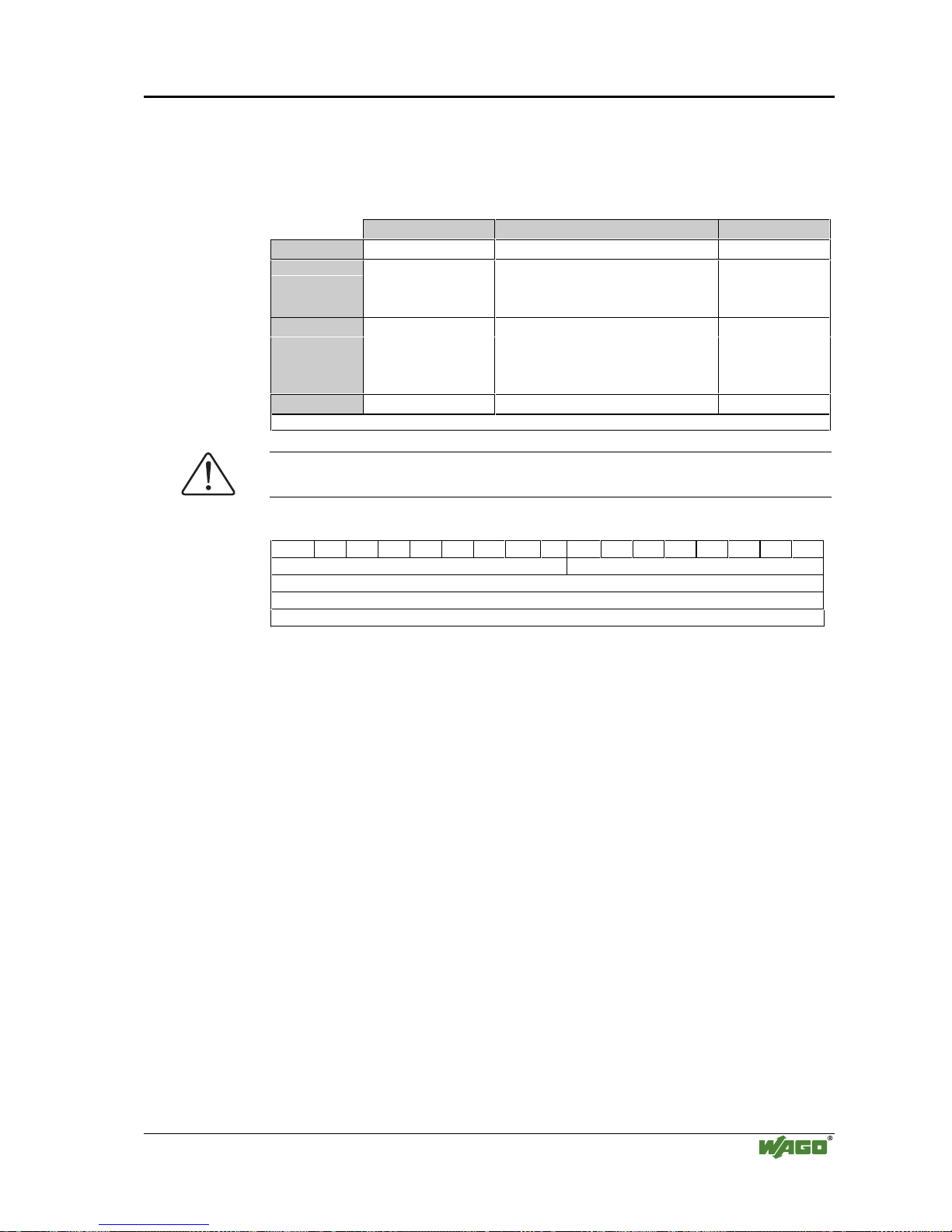
Fieldbus controller 750-842 • 69
Data exchange
Modular I/O System
ETHERNET TCP/IP
3.2.5.2.3 Absolute addresses
The direct display of individual memory cells (absolute addresses) in accordance with IEC 61131-3 is made using special character strings in accordance with
the following table:
Position Character Designation Comments
1 %
Starts absolute address
2
I Input
Q Output
MFlag
3
X* Single bit Data width
B Byte (8 Bits)
W Word (16 Bits)
D Double word (32 Bits)
4
Address
* The character ‘X’ for bits can be deleted
Table 3.8: Absolute addresses
Note
Enter the absolute address character strings without blanks!
Example: Absolute addresses for input:
%IX14. .15 .14 .13 .12 .11 .10 .9 .8 .7 .6 .5 .4 .3 .2 .1 .0
%IB29 %IB28
%IW14
%IDW7
* The character ‘X’ for single bits can be deleted
Table 3.9: Example for input absolut e addresses
Address calculation (depending upon the word address):
Bit address: word address .0 to .15
Byte address: 1. Byte: 2 x word address
2. Byte: 2 x word address + 1
Dword address:
word address (even numbers) / 2
or word address (uneven numbers) / 2, rounded off
Page 74

70 • Fieldbus controller 750-842
Data exchange
Modular I/O System
ETHERNET TCP/IP
3.2.5.3 Data exchange between master and I/O modules
The data exchange between the MODBUS master and the I/O modules is
made via the MODBUS functions implemented in the controller by reading
and writing in bits or bytes.
The controller handles four different types of process data:
• Input words
• Output words
• Input bits
• Output bits
The word for word access to the digital input and output modules is made in
accordance with the following table:
Digital inputs/
outputs
16. 15. 14. 13. 12. 11. 10. 9. 8. 7. 6. 5. 4. 3. 2. 1.
Prozess data
word
Bit15Bit14Bit13Bit12Bit11Bit10Bit9Bit8Bit7Bit6Bit5Bit4Bit3Bit2Bit1Bit
0
High-Byte Low-Byte
Byte
D1 D0
Table 3.10: Allocation of digital inputs/outputs to process data word acc. Intel format
Adding 0x0200 to the MODBUS address permits to read back the outputs.
The register functions addressing can be by the means of the implemented
MODBUS function codes (read/write). The individual register address is referenced instead of the address of a module channel.
0x000
0x0FF
0x000
(0x200)
0x0FF
(0x2FF)
PII = Process Input
Image
PIO = Process Output
Image
MODBUS master
PII
PIO
I/O modules
Inputs
Outputs
Programmable Fieldbus Controller
Fig. 3-27: Data exchange between MODBUS master and I/O modules g012929e
Page 75

Fieldbus controller 750-842 • 71
Data exchange
Modular I/O System
ETHERNET TCP/IP
3.2.5.4 Data exchange between PLC functionality (CPU) and I/O modules
Through absolute addresses, the PLC functionality (CPU) of the PFC can directly address the bus module data.
The PFC addresses the input data with absolute addresses. The data can then
be processed, internally in the controller, through the IEC 61131-3 program,
whereby the flags are filed in a permanent memory area. Following this, the
linking results can be directly written in the output data via absolute addressing.
%IW0 %QW0
%QW255%IW255
PII = Process Input
Image
PIO = Process Output
Image
Inputs
Outputs
I/O modules
750-4xx....6xx
PII
PIO
PLC functionality (CPU)
Inputs
Outputs
Programmable Fieldbus Controller
Fig. 3-28: Data exchange between PLC functionality (CPU) and I/O modules g012943e
Page 76
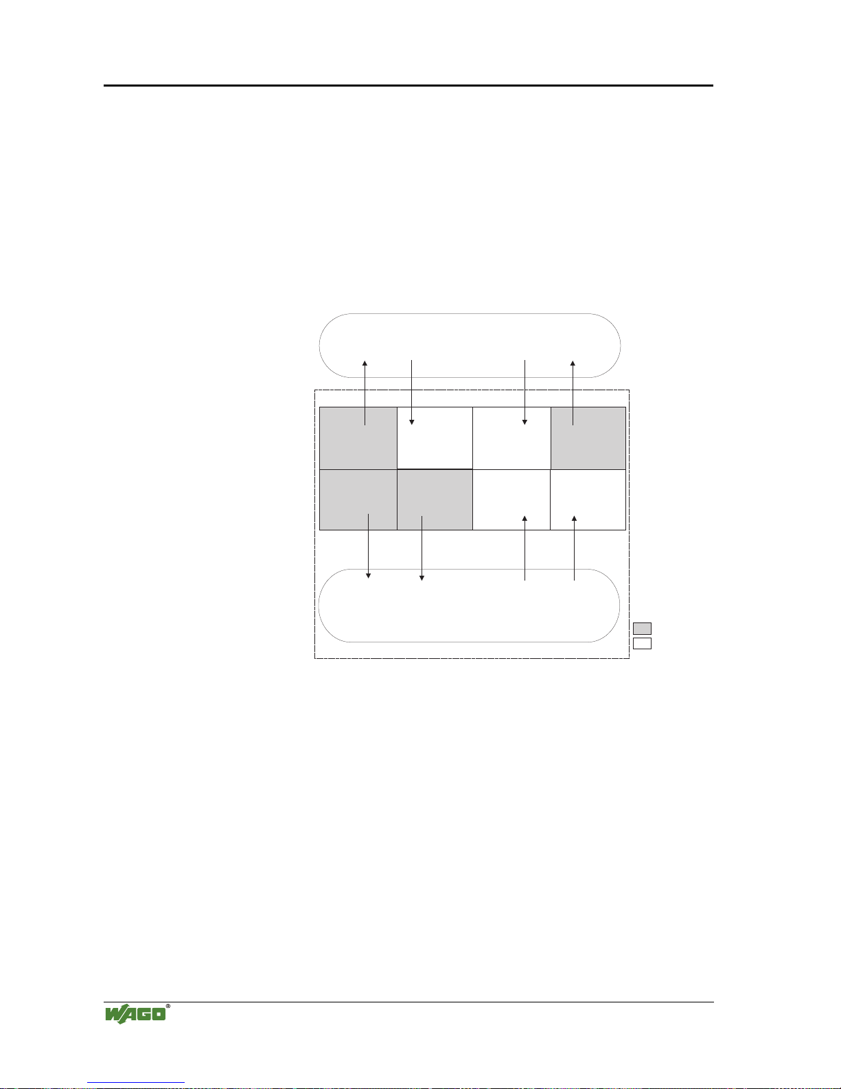
72 • Fieldbus controller 750-842
Data exchange
Modular I/O System
ETHERNET TCP/IP
3.2.5.5 Data exchange between master and PLC functionality (CPU)
The MODBUS master and the PLC functionality (CPU) of the PFC regard the
data in a different manner.
Variables data created by the master reach the PFC as input variables and are
further treated there.
Data created in the PFC is sent to the master through the fieldbus as output
variables.
In the PFC the system can access the variable’s data as from I/O word address
256 (double word address 128, byte address 512).
0x000
0x0FF
0x100
0x1FF
%IW0
%IW255
%QW256
%QW511
0x000
(0x200)
0x0FF
(0x2FF)
0x100
(0x300)
%QW0
%IW256
%QW255
%IW511
0x1FF
(0x3FF)
PII = Process Input
Image
PIO = Process Output
Image
MODBUS master
PII
PIO
PLC functionality (CPU)
Inputs
Outputs
Programmable Fieldbus Controller
Data from point of view
of PLC functionality
Data from point of view
of MODBUS master
I/O modules variables
I/O modules variables
I/O modules variables I/O modules variables
PII
SPS-PII SPS-PIO
Fig. 3-29: Data exchange between MODBUS master and PLC functionality g012944e
Data access by the MODBUS master
The data can only be accessed by the MODBUS master either word by word or
bit by bit.
Addressing the data from the bus modules starts with word 0 for a wordby-word access, and also with 0 in word 0 for bit 0 for a bit-by-bit access.
Addressing the data from the variables starts with word 256 for a word-byword access, and then, with a bit-by-bit access, addressing starts from:
4096 for bit 0 in word 256
4097 for bit 1 in word 256
...
8191 for bit 15 in word 511.
Page 77

Fieldbus controller 750-842 • 73
Data exchange
Modular I/O System
ETHERNET TCP/IP
The bit number can be defined using the following formula:
BitNo = (Word * 16) + Bitno_in_Word
Data access by the PLC functionality
When accessing the same data, the PLC functionality of the PFCs uses a different type of addressing.
When declaring 16 bit variables, the PLC addressing is identical to the addressing of the MODBUS master made word-by-word.
When declaring Boolean variables (1 bit) a notation different to that of the
MODBUS is used.
The bit address is composed of the elements word address and bit number in
the word, separated by a dot.
Example:
Bit access MODBUS to bit number 4097 => bit addressing in the PLC
<Wordno>.<Bitno> = 0.1
The PLC functionality of the PFC can also access the data byte-by-byte and
double word-by-double word.
With the bytewise access, the addresses are computed according to the following formula:
High-Byte Address = Word address*2
Low-Byte Address = (Word address*2) + 1
With the access by a double word, the address is computed according to the
following formula:
Double word address = High word address/2 (rounded off)
or = Low word address/2
3.2.5.6 Common access of MODBUS master and PLC functionality to outputs
The process illustration of outputs is described both by the MODBUS master
as well as by the PLC functionality, so that the I/O module outputs can be set
or reset from both sides. Design the user programs of the MODBUS master
and the PLC functionality such that conflicting instructions for simultaneous
setting or resetting of outputs is excluded.
Page 78

74 • Fieldbus controller 750-842
Data exchange
Modular I/O System
ETHERNET TCP/IP
3.2.5.7 Address review
%IB0, %IW0, %ID0, %IX0.0
%IB511, %IW255, %ID127, %IX255.15
%IB0+x, %IW0+x, %ID0+x, IX0+x.0
%IB31+x, %IW15+x, %ID7+x, %IX15+x.15
%QB0, %QW0, %QD0, %QX0.0
%QB511, %QW255,%QD127,%QX255.15
%QB0, %QW0, %QD0, %QX0.0
%QB511,%QW255,%QD127, %QX255.15
%QB0+x, %QW0+x, %QD0+x, %QX0+x.0
%QB0+x, %QW0+x, %QD0+x, QX0+x.0
%QB31+x,%QW15+x,%QD7+x,%QX15+x.15
%QB512,%QW256, %QD128, %QX256.0
%QB1023,%QW511,%QD255,%QX511.1
%QB512,%QW256, %QD128, %QX256.0
%QB1023,%QW511,%QD255,%QX511.15
%IB512, %IW256, %ID128, %IX256.0
%IB1023, %IW511, %ID255, %IX511.15
%IB512, %IW256, %ID128, %IX256.0
%IB1023, %IW511, %ID255, %IX511.15
%IB512, %IW256, %ID128, %IX256.0
%IB1023, %IW511, %ID255, %IX511.15
%IB512, %IW256, %ID128, %IX256.0
%IB1023, %IW511, %ID255, %IX511.15
%QB31+x,%QW15+x, %QD7+x, %QX15+x.15
MODBUS
0x000
0x0FF
255
0
0x000 ... 0x00F
0 ... 15
0x0F0 ... 0X0FF
240 ... 255
0x000
0x0FF
0
255
0x1000 ... 0x100F
4096 ... 4111
511
0 ... 15
0x0F0 ... 0X0FF
0x000 ... 0x00F
240 ... 255
0x200 ... 0x20F
512 ... 527
0x2F0 ... 0X2FF
752 ... 767
0x1FF
0x200
0x2FF
512
767
0x100
0x1FF0 ... 0x1FFF
8176 ... 8191
256
511
0x1FF
0x100
256
768
0x300
1023
0x3FF
0x1000 ... 0x100F
4096 ... 4111
0x1FF0 ... 0x1FFF
8176 ... 8191
0x2000 ... 0x200F
8192 ... 8207
0x2FF0 ... 0x2FFF
12272 ... 12287
MODBUS addresses
PLC addresses
hex
dec
I/O modules
750-4xx....6xx
AI
DI
AO DO
PII
Digital PII
PIO
PIO
Digital PIO
Digital PIO
PLC PIO
PLC PIO
PLC PII
PLC PII
PLC PII
PLC PII
AI
AO
PLC functionality
x: depending on the number of connected analog I/O modules
Controller 750-842
PII = Process Input Image
PIO = Process Output Image
AI = Analog Inputs
DI = Digital Inputs
AO = Analog Outputs
DO = Digital Outputs
AI
AODIDO
PLC = Programmable
ontrollerLogic C
fieldbus node
Fig. 3-30: Address review, controller g012932e
Page 79

Fieldbus controller 750-842 • 75
Starting up ETHERNET TCP/IP fieldbus nodes
Modular I/O System
ETHERNET TCP/IP
3.2.6 Starting up ETHERNET TCP/IP fieldbus nodes
This chapter shows the step-by-step procedure for starting up a
WAGO ETHERNET TCP/IP fieldbus node. The following also contains a description of how to view the controller-internal HTML pages.
Following this, information regarding PFC programming with
WAGO-I/O-PRO 32 are shown.
Attention
This description is given as an example and is limited to the execution of a
local startup of an individual ETHERNET fieldbus node with a computer running under windows which is not connected to a network.
Direct Internet connection should only be performed by an authorized network
administrator and is, therefore, not described in this manual.
The procedure contains the following steps:
1. Noting the MAC-ID and establishing the fieldbus node
2. Connecting the PC and fieldbus node
3. Determining the IP address
4. Allocation of the IP address to the fieldbus node
5. Function of the fieldbus tests
6. Viewing the HTML pages
3.2.6.1 Note the MAC-ID and establish the fieldbus node
Before establishing your fieldbus node, please note the hardware address
(MAC-ID) of your ETHERNET fieldbus controller.
This is located on the rear of the fieldbus controller and on the self-adhesive
tear-off label on the side of the fieldbus controller.
MAC-ID of the fieldbus controller: ----- ----- ----- ----- ----- -----.
3.2.6.2 Connecting PC and fieldbus node
Connect the assembled ETHERNET TCP/IP fieldbus node via a hub or directly to the PC using a 10Base-T cable.
Attention
For a direct connection, a “crossover” cable is required instead of a parallel
cable.
Now start the PC, functioning as master and BootP server, and apply power to
the fieldbus coupler (DC 24 V power pack). Once the operating voltage has
been switched on, the initialization starts. The fieldbus controller determines
the configuration of the bus modules and creates the process image.
During the startup the 'I/O' LED (Red) flashes at high frequency.
When the 'I/O' LED and the 'ON' LED light up green, the fieldbus controller is
ready for operation.
If an error has occurred during startup, it is indicated as an error code by the
'I/O'-LED flashing (red).
Page 80
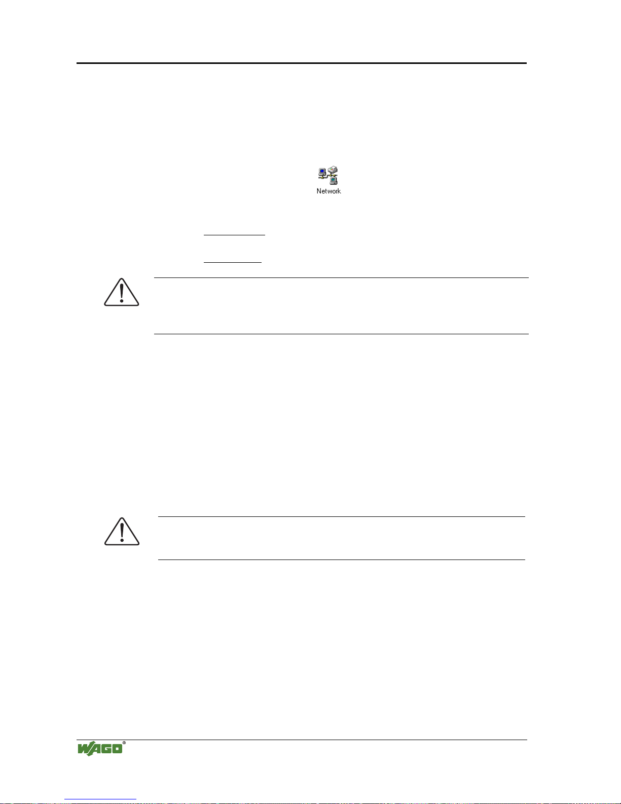
76 • Fieldbus controller 750-842
Starting up ETHERNET TCP/IP fieldbus nodes
Modular I/O System
ETHERNET TCP/IP
3.2.6.3 Determining IP addresses
If your PC is already connected to an ETHERNET network, it is very easy to
determine the IP address of your PC. To do this, proceed as follows:
1. Go to the Start menu on your screen, menu item Settings and click on Con-
trol Panel.
2. Double click the icon Network.
The network dialog window will open.
3. - Under Windows NT: Select the register: Protocols and mark
the entry TCP/IP protocol.
- Under Windows 9x: Select the register: Configuration and mark
the entry TCP/IP network card.
Attention
If the entry is missing, please install the respective TCP/IP component and restart
your PC. The Windows-NT installation CD, or the installations CD for Windows
9x is required for the installation.
4. Subsequently, click the button "Properties...".
The IP address and the subnet mask are found in the ‘IP address’ tab.If applicable, the gateway address of your PC is found in the ‘Gateway’ tab.
5. Please write down the values:
IP address PC: ----- . ----- . ----- . ----Subnet mask: ----- . ----- . ----- . ----Gateway: ----- . ----- . ----- . -----
6. Now select a desired IP address for your fieldbus node.
Attention
When selecting your IP address, ensure that it is in the same local network in
which your PC is located.
7. Please note the IP address you have chosen:
IP address fieldbus node: ----- . ----- . ----- . -----
3.2.6.4 Allocating the IP address to the fieldbus node
A prerequisite for a communication with the controller is the assignment of an
IP address.
The address can be transferred through BootP or a PFC program. With the
PFC program, this is possible in WAGO-I/O-PRO 32 using the library function "ETHERNET Set-Network-Config".
Page 81

Fieldbus controller 750-842 • 77
Starting up ETHERNET TCP/IP fieldbus nodes
Modular I/O System
ETHERNET TCP/IP
The following describes how to allocate the IP address for the fieldbus node
using the WAGO BootP server by way of an example. You can download a
free copy from WAGO over the Internet under:
http://www.wago.com/wagoweb/usa/eng/support/downloads/index.htm.
Note
The IP address can be allocated under other operating systems (i.e. under Linux) as well as with any other BootP servers.
Attention
The IP address can be allocated in a direct connection via a crossover cable or
via a parallel cable and a hub. An allocation over a switch is not possible.
BootP table
Note
Prerequisite for the following steps is the correct installation of the WAGO
BootP server.
1. Go to the Start menu, menu item Programs / WAGO Software / WAGO
BootP Server and click on WAGO BootP Server configuration. Or go to
Start menu, menu item Programs/WAGO Software/WAGO BootP
Server and click on WAGO BootP Server then click on the Edit
Bootptab button located on the right hand side of the display.
An editable table will appear: "bootptab.txt".
This table displays the data base for the BootP server. Directly following
the list of all notations used in the BootP table there are two examples for
the allocation of an IP address.
"Example of entry with no gateway" and "Example of entry with gateway".
Fig. 3-31: BootP table p012908e
Page 82
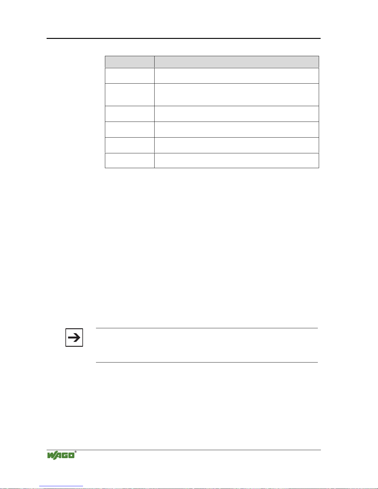
78 • Fieldbus controller 750-842
Starting up ETHERNET TCP/IP fieldbus nodes
Modular I/O System
ETHERNET TCP/IP
The examples mentioned above contain the following information:
Declaration Meaning
node1,
node2
Any name can be given for the node here.
ht=1 Specify the hardware type of the network here.
The hardware type for ETHERNET is 1.
(The numbers are described in RFC1700)
ha=0030DE000100
ha=0030DE000200
Specify the hardware address or the MAC-ID of the ETHERNET
fieldbus controller (hexadecimal).
ip= 10.1.254.100
ip= 10.1.254.200
Enter the IP address of the ETHERNET fieldbus controller (decimal)
here.
T3=0A.01.FE.01 Specify the gateway IP address here.
Write the address in hexadecimal form.
sm=255.255.0.0 In addition enter the Subnet-mask of the subnet (decimal), where the
ETHERNET fieldbus controller belongs to.
No gateway is required for the local network described in this example.
Therefore, the first example: "Example of entry with no gateway" can be
used.
2. Move the mouse pointer to the text line: "Kein-
Proxy:ht=1:ha=0030DE000100:ip=10.1.254.100" and delete the 12 character
hardware address which is entered after ha=...
Enter the MAC-ID of your own network controller.
3. If you want to give your fieldbus node a name, delete the name "node1" and
enter any name in its place.
4. To assign the controller a desired IP address, delete the IP address specified
in the example which is entered after ip=...
Replace it with the IP address you have selected, making sure you are separating the 3 digit numbers by a decimal.
5. Because the second example is not necessary at present, insert a “#” in front
of the text line of the second example: "# hamburg:hat=1:ha=003 0DE 0002
00:ip=10.1.254.200:T3=0A.01.FE.01", so that this line will be ignored.
Note
To address more fieldbus nodes, enter a corresponding text line showing the
corresponding entries for each node. Also note that the # symbol tells the
BootP server to ignore any data after it, for that specific line.
6. Save the altered settings in this text file "bootptab.txt". To do this go to the
File menu, menu item Save, and close the editor.
Page 83
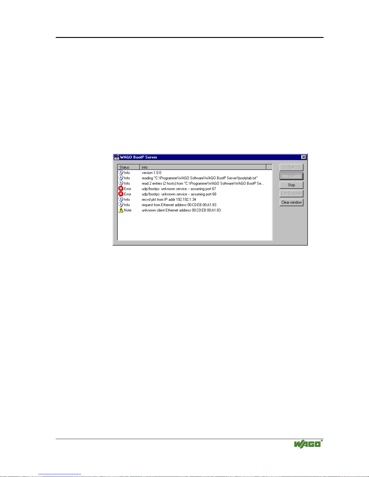
Fieldbus controller 750-842 • 79
Starting up ETHERNET TCP/IP fieldbus nodes
Modular I/O System
ETHERNET TCP/IP
BootP Server
7. Now open the dialog window for the WAGO BootP server by going to the
Start menu on your screen surface, menu item Program /
WAGO Software / WAGO BootP Server and click on WAGO BootP
Server.
8. Click on the "Start" button in the opened dialog window.
This will activate the inquiry/response mechanism of the BootP protocol.
A series of messages will be displayed in the BootP server. The error messages indicate that some services (e.g. port 67, port 68) in the operating system have not been defined. DO NOT BE ALARMED THIS IS THE
CORRECT OPERATION FOR THIS EXAMPLE.
Fig. 3-32: Dialog window of the WAGO BootP server with messages P012909d
9. Now it is important to restart the controller by resetting the hardware . This
ensures that the new IP address will be accepted by the controller.
To do this, cycle power to the fieldbus controller for approximately 2 seconds or press the operating mode switch down which is located behind the
configuration interface flap located on the front of the coupler.
Following this, you should see a reply from the buscoupler stating that the IP
address has been accepted (no errors). The IP address is now permanently
stored in the coupler and will be retained even following the removal of the
coupler or a longer voltage failure. The only way the IP address can be
changed is by using the BootP software again.
10. Subsequently, click on the "Stop" button and then on the "Exit" button, to
close the BootP Server .
3.2.6.5 Testing the function of the fieldbus node
1. To test the communication with the coupler and the correct assignment of
the IP address call up the DOS prompt under Start menu / Program / MS-
DOS Prompt.
2. Enter the command: "ping" with the IP address you have assigned in the
following form:
ping [space] XXXX . XXXX . XXXX . XXXX (=IP address).
Page 84
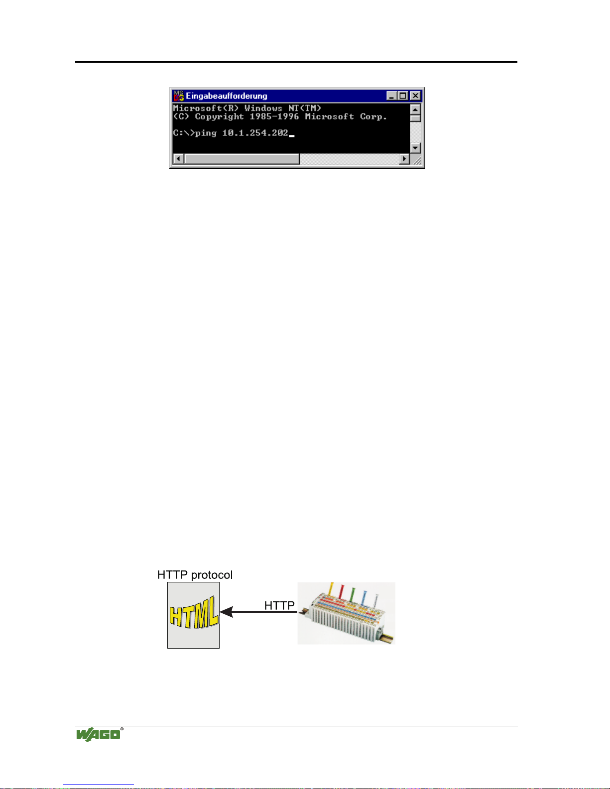
80 • Fieldbus controller 750-842
Starting up ETHERNET TCP/IP fieldbus nodes
Modular I/O System
ETHERNET TCP/IP
Example: ping 10.1.254.202
Fig. 3-33: Example for the function test of a fieldbus node P012910e
3. When the Return key has been pressed, your PC will receive a response from
the controller, which will then be displayed in the DOS prompt.
If the error message: "Timeout" appears instead, please compare your entries
again to the allocated IP address and check all conections.
4. Also note that the TXD/RXD light will flash verifying each response
5. When the test has been performed successfully, you can close the DOS prompt.
The network node has now been prepared for communication.
3.2.6.6 Viewing the HTML pages
The information saved in the fieldbus controller can be viewed as an HTML
page using a web browser.
• Information on the fieldbus node (Terminal Status):
- Number of digital, analog or complex modules and their model numbers
- Representation of the process image
• Information on the fieldbus controller (Controller and Network Details):
- Order number
- Firmware version
- MAC-ID
- IP address
- Gateway address (if applicable)
- Subnet mask
- Number of transmitted and received packets
• Diagnostic information on the fieldbus controller (Controller Status):
- Error code
- Error argument
- Error description
Fig. 3-34: Viewing the information through the HTTP protocol G012916d
Page 85

Fieldbus controller 750-842 • 81
Starting up ETHERNET TCP/IP fieldbus nodes
Modular I/O System
ETHERNET TCP/IP
Please proceed as follows:
1. Open a web browser such as Microsoft Internet-Explorer, Netscape Navi-
gator, ...
2. Simply enter the IP address of your fieldbus node in the address field of the
browser and press the Enter key.
The first HTML page with the information on your fieldbus controller will
be displayed in the browser window. Use the hyperlinks to find out more
information.
Attention
If the pages are not displayed after local access to the fieldbus node, then define in your web browser that, as an exception, no proxyserver is to be used for
the IP address of the node.
Page 86

82 • Fieldbus controller 750-842
Programming the PFC with WAGO-I/O-PRO 32
Modular I/O System
ETHERNET TCP/IP
3.2.7 Programming the PFC with WAGO-I/O-PRO 32
Due to the IEC 61131 programming of the ETHERNET TCP/IP fieldbus controller 750-842 you have the option to use the functionality of a PLC beyond
the functions of fieldbus coupler 750-342.
An application program according to IEC 61131-3 is created using the programming tool WAGO-I/O-PRO 32.
This manual, however, does not include a description of how to program with
WAGO-I/O-PRO 32. In contrast, the following chapters are to describe the
special modules for WAGO-I/O-PRO 32 for you to utilize explicitly for pro-
gramming the ETHERNET TCP/IP fieldbus controller.
The description also deals with the way of transmitting the IEC 61131-3 program into the controller and loading a suitable communication driver.
i
More information
For a detailed description of how to use the software, please refer to the
WAGO-I/O-PRO 32 manual (order No.: 759-122 / 000-001).
3.2.7.1 WAGO-I/O-PRO 32 library elements for ETHERNET
You are offered various libraries for different IEC 61131-3 programming applications in WAGO-I/O-PRO 32. They contain modules of universal use and
can, thereby, facilitate and speed up the creation of your program. As standard,
the library ’standard.lib’ is available to you.
The libraries described in the following are specifically intended for
ETHERNET projects with WAGO-I/O-PRO 32:
• "ETHERNET. lib"
(contains elements for the ETHERNET fieldbus communication),
• "EtherTCPmodbus.lib"
(contains elements for the MODBUS TCP fieldbus communication) and
• "Internal types for EtherTCPmodbus.lib"
(contains elements for an easier access to the MODBUS/TCP requests und
responses).
These libraries are loaded on the WAGO-I/O-PRO CD.
Having integrated these libraries, you have access to their POUs, data types
and global variables which can be used in the same manner as those defined by
yourself.
i
More information
For a detailed description of the POUs and the software operation, please refer
to the WAGO-I/O-PRO 32 manual (order No.: 759-122 / 000-001).
Page 87

Fieldbus controller 750-842 • 83
Programming the PFC with WAGO-I/O-PRO 32
Modular I/O System
ETHERNET TCP/IP
3.2.7.1.1 ETHERNET.lib
Element Description
ETHERNET_CLIENT_CLOSE Function block to close a client socket.
ETHERNET_CLIENT_OPEN
Function block to create a client socket. *
)
ETHERNET_GET_NETWORK_CONFIG Function block to get the node’s network confi-
guration.
ETHERNET_READ Function block to read date received from a
remote system.
ETHERNET_SERVER_CLOSE Function block to close a Server socket with all
underlying connections (clients connected to
the server).
ETHERNET_SERVER_OPEN Function block to create a Server socket. It is a
base for a communication to a remote system..*
)
ETHERNET_SET_NETWORK_CONFIG Function block to set the node’s network confi-
guration.
ETHERNET_VERSION Function to get the library’s current version.
ETHERNET_WRITE Function block to write data to a remote sy-
stem.
ETH_ERROR (Data type) Data type defines the error codes returned by
the ETHERNE T function blocks.
SEL_PROTOCOL (Data type) Data type defines the transport protocol to use.
Is used by ETHERNET_CLIENT_OPEN and
ETHERNET_SERVER_OPEN.
SEL_TYPE (Data type) Data type defines the semantics of communica-
tion. Is used by ETHERNET_CLIENT_OPEN
and ETHERNET_SERVER_OPEN).
*) The maximum number of connecti ons open at a ti me is 2. You might have to t erminate
existing connections to ETHERNET_CLIENT_CLOSE or ETHERNET_SERVER_CLOSE.
3.2.7.1.2 EtherTCPmodbus.lib
Element Description
HTONS Function converts t he value ShortNumber from
Intel format to Motorola format.
RECV_MODBUS_MESSAGE Function to receive the answer to a
MODBUS/TCP request over a TCP connec-
tion.*
)
SEND_MODBUS_MESSAGE Function to send a MODBUS/TCP message
over a TCP connection.*
)
MODBUS_FC (Data type) Data type, defines the function code to use. (Is
used by SEND_MODBUS_MESSAGE and
RECV_MODBUS_MESSAGE)
*) To prevent a complete filling of the buffer, the module SEND_MODBUS_MESSAGE
should always preceed the RECV_MODBUS_MESSAGE.
Page 88

84 • Fieldbus controller 750-842
Programming the PFC with WAGO-I/O-PRO 32
Modular I/O System
ETHERNET TCP/IP
3.2.7.1.3 Internal types for EtherTCPmodbus.lib
Element Description
MODBUS_HEADER
MODBUS_FMC_REQUEST
MODBUS_FMC_RESPONSE
MODBUS_RC_REQUEST
MODBUS_RC_RESPONSE
MODBUS_RID_REQUEST
MODBUS_RID_RESPONSE
MODBUS_RIR_REQUEST
MODBUS_RIR_RESPONSE
MODBUS_RMR_REQUEST
MODBUS_RMR_RESPONSE
MODBUS_WC_REQUEST
MODBUS_WC_RESPONSE
MODBUS_WMR_REQUEST
MODBUS_WMR_RESPONSE
MODBUS_WSR_REQUEST
MODBUS_WSR_RESPONSE
This types are internally used by the functions
SEND_MODBUS_MESSAGE and
RECV_MODBUS_MESSAGE. They map the
MODBUS/TCP requests and responses, so that
an easier access to the message fields can be
done.
3.2.7.2 IEC 61131-3-Program transfer
Program transfer from the PC to the controller following programming of the
desired IEC 61131 application can be made in two different ways:
• via the serial interface or
• via the fieldbus.
One suitable communication driver each is required for both types.
i
More information
For information on the installation of the communication drivers as well as
details regarding the use of the software, please refer to the
WAGO-I/O-PRO 32 manual (order No.: 759-122 / 000-001).
Page 89

Fieldbus controller 750-842 • 85
Programming the PFC with WAGO-I/O-PRO 32
Modular I/O System
ETHERNET TCP/IP
3.2.7.2.1 Transmission via the serial interface
Use the WAGO communication cable to produce a physical connection to the
serial interface. This is contained in the scope of delivery of the programming
tool IEC 1131-3, order No.: 759-332/000-002, or can be purchased as an accessory under order No.: 750-920.
Connect the COMX port of your PC with the communication interface of your
controller using the WAGO communication cable.
A communication driver is required for serial data transmission. In
WAGO-I/O-PRO 32, this driver and its parameterization are entered in the
"Communication parameters" dialog.
1. Start the WAGO-I/O-PRO 32 software by ’Start/Programs’ or by double
clicking on the WAGO-I/O-PRO-32 symbol on your desk top.
2. In the "Online" menu click on the "Communication parameters" menu
point.
The dialog "Communication parameters" opens. The basic setting of this
dialog does not have any entries.
3. In the selection window mark the desired driver on the right-hand dialog
side (i.e. "Serial (RS232)", to configure the serial connection between PC
and the controller).
4. In the center window of the dialog, the following entries have to appear: -
Parity: Even and -Stop bits: 1.
If necessary, change the entries accordingly.
You can now begin testing the controller.
Note
To be able to access the controller, ensure that the operating mode switch
of the controller is set to the center or the top position.
5. Under "Online" click on the "Log-on" menu point to log into the control-
ler.
(The WAGO-I/O-PRO 32 server is active during online operation. The
communication parameters cannot be polled.)
6. If no program is in the controller, now a window appears asking whether or
not the program is to be loaded.
Confirm with "Yes".
Subsequently the current program will be loaded.
7. As soon as the program is loaded, you can start program with the "Online"
menu, menu point "Start".
At the right-hand end of the status bar, the system signals "ONLINE
RUNNING".
8. To terminate the online operation, return to the "Online" menu and click
on the "Log-off" menu point.
Page 90

86 • Fieldbus controller 750-842
Programming the PFC with WAGO-I/O-PRO 32
Modular I/O System
ETHERNET TCP/IP
3.2.7.2.2 Transmission by the fieldbus
The PC and the controller are physically connected via the Ethernet cable.
For data transmission, a suitable communication driver is required. This driver
is entered in the "Communication parameters" dialog in WAGO-I/O-PRO
32.
1. Start the WAGO-I/O-PRO 32 software by ’Start/Programs’ or by double
clicking on the WAGO-I/O-PRO-32 symbol on your desk top.
2. In the "Online" menu click on the "Communication parameters" menu
point.
The "Communication parameters" dialog opens. The basic setting of this
dialog has no entries. This is assuming that you have not used the software
to configure any other couplers.
3. Select the New button on the right hand side of the Communications Pa-
rameters dialog box. Select the “Ethernet_TCP_IP” driver (it is the last entry). You can enter a name in the “Name” field located in the top-left of the
dialog box. After all data has been entered click OK.
4. While the Ethernet driver is selected (click on the new driver you selected
in the previous step). The following entries have to appear in the center
window of the dialog: -Port No.: 2455 and –IP address: (the IP address of
your controller assigned via BootP).
If necessary, change the entry accordingly.
You can now begin testing the controller.
Note
To be able to access the controller, the coupler has to have an IP address,
and the operating mode switch of the controller must be in the centerre or
top position.
5. Under "Online" click on the "Log-on" menu point to log into the control-
ler.
(During online operation, the WAGO-I/O-PRO 32 server is active. The
communication parameters cannot be polled.)
6. If no program is contained in the controller, a window appears asking
whether or not the program is to be loaded.
Confirm with "Yes".
Subsequently the current program is loaded.
7. As soon as the program is loaded, you can start it by selecting "Online"
menu, then "Start".
At the right-hand end of the status bar, the system displays "ONLINE
RUNNING".
8. To terminate the online operation, return by the "Online" menu and click
on the "Log-off" menu point.
Page 91
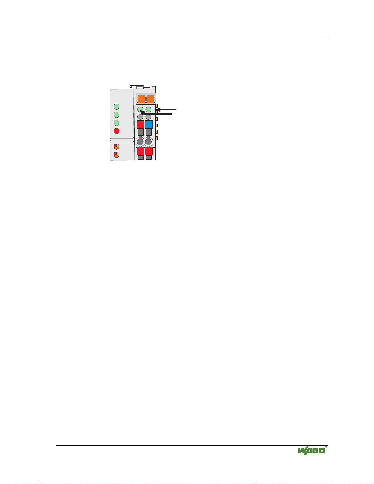
Fieldbus controller 750-842 • 87
LED Display
Modular I/O System
ETHERNET TCP/IP
3.2.8 LED Display
The controller possesses several LED’s for on site display of the controller operating status or the complete node.
24V
0V
++
01 02
ON
LINK
TxD/RxD
I/O
ETHERNET
C
D
B
A
ERROR
USR
status
voltage supply
-power jumper contacts
-system
Fig. 3-35: Display elements 750-842 g012902e
A differentiation between two LED groups is made.
The first group = fieldbus contains the solid color LEDs having the designa-
tion ON (green), LINK (green), TxD/RxD (green) and ERROR (red) indicating the operating status of the communication via ETHERNET.
The second group = internal bus consists of the three-color I/O LED
(red/green/orange). This LED is used to display the status of the internal bus,
i. e. the status of the fieldbus node.
The three-color USR-LED can be accessed by a user program in the programmable fieldbus controller.
LEDs located on the right-hand side in the coupler power supply section show
the status of the supply voltage.
3.2.8.1 Blink code
A blink code displays detailed fault messages. A fault is cyclically displayed
using up to 3 different blink sequences.
• The first blink sequence (approx. 10 Hz) indicates the fault display.
• After a pause, a second blink sequence appears (approx. 1 Hz). The number
of blink impulses gives the fault code.
• The third blink sequence (approx. 1 Hz) appears following a further pause.
The number of blink pulses indicates the fault argument (where the
faulty module is physically located on the node).
Page 92
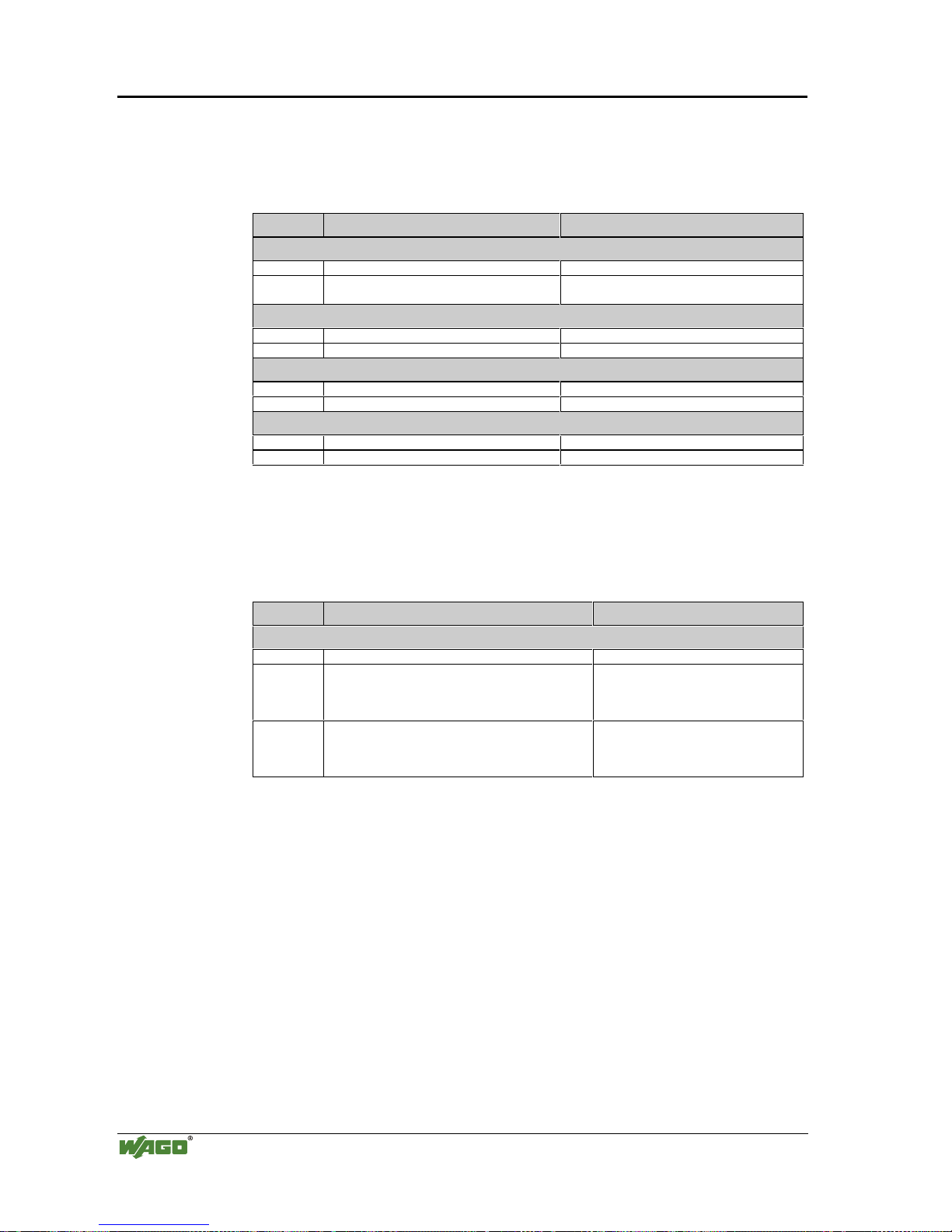
88 • Fieldbus controller 750-842
LED Display
Modular I/O System
ETHERNET TCP/IP
3.2.8.2 Fieldbus status
The operating status of the communication via ETHERNET is signalled via
the top LED group (ON, LINK, TxD/RxD and ERROR).
LED Meaning Trouble shooting
ON
green Fieldbus initialization is correct
OFF Fieldbus initialization is not correct,
no function or self test
Check the supply voltage (24V and 0V),
check the IP configuration
LINK
green Link to a physical network exists
OFF No link to a physical network Check the fieldbus connection.
TxD/RxD
green Data exchange taking place
OFF No data exchange
ERROR
red Error on the fieldbus
OFF No error on the fieldbus, normal operation
3.2.8.3 Node status
The operating status of the communication with the internal bus is signalled by
the bottom I/O-LED.
LED Meaning Trouble shooting
I/O
green Fieldbus controller operating perfectly
red a) During startup of fieldbus controller:
Internal bus being initialized,
Startup displayed by LED flashing fast for approx.
1-2 seconds
red b) After startup of fieldbus controller:
Errors, which occur, are indicated by three conse cutive flashing sequences. There is a short pause
between each sequential.
Evaluate the fault message (fault code and
fault argument).
The controller starts up after switching on the supply voltage. The "I/O" LED
blinks. The "I/O" LED has a steady light following a fault free start-up.
In the case of a fault the "I/O" LED continues blinking. The fault is cyclically
displayed by the blink code.
Page 93

Fieldbus controller 750-842 • 89
LED Display
Modular I/O System
ETHERNET TCP/IP
“I/O”-LED is blinking
Test o.k.?
No
Yes
“I/O”-LED is shining
ready for operation
2nd break
1st break
“I/O” LED
1st flash sequence
(Introduction of the
error indication)
“I/O” LED
2nd flash sequence
Error code
(Number of flash cycles)
“I/O” LED
3rd flash sequence
Error argument
(Number of flash cycles)
Coupler/Controller starts up
Switching on
the power supply
Fig. 3-36: Signalling of the LED for indication of the node status g012911e
After overcoming a fault restart the controller by cycling the power.
Page 94

90 • Fieldbus controller 750-842
LED Display
Modular I/O System
ETHERNET TCP/IP
3.2.8.4 Fault message via blink code from the I/O-LED
Fault argument Fault description
Fault code 1: Hardware and Configuration fault
0 EEPROM check sum fault / check sum fault in the parameter area of the flash memory
1 Overflow of the int ernal buffer memory for the inline code
2 Unknown data type
3 Module type of the flash program memory could not be determined / is incorrect
4 Fault when writing in the FLASH memory
5 Fault when deleting the FLASH memory
6 Changed I/O module configuration determined after AUTORESET
Fault code 2: Fault in programmed configuration
0 Incorrect table entry
Fault code 3: Internal bus command fault
0 No fault argument is put out.
Fault code 4: Internal bus data fault
0 Data fault on internal bus or
Internal bus interruption on controller
n* (n>0) Internal bus interrupted after I/O module n
Fault code 5: Fault duri ng register communication
n* Internal bus fault during register communication after I/O module n
Fault code 6: Fieldbus specific errors
1 No answer from the BootP server
2 ETHERNET controller not rec ognized
3Invalid MACID
4 TCP/IP initialization error
Fault code 7: I/O module is not supported
n* I/O module at position n is not supported
Fault code 8: not used
0 Fault code 8 is not used.
Fault code 9: CPU-TRAP error
1 Illegal Opcode
2 Stack overflow
3 Stack underflow
4NMI
* The number of blink pulses (n) indicates the position of the I/O module. I/O modules
without data are not counted (i.e. supply modules without diagnostics).
Example for a fault message
Fault: The 13th I/O module has been removed.
4. The "I/O" LED starts the fault display with the first blink sequence (approx.
10 Hz).
5. The second blink phase (approx. 1 Hz) follows the first pause. The "I/O"
LED blinks four times and thus signals the fault code 4 (internal bus data
fault).
6. The third blink sequence follows the second pause. The "I/O ERR" LED
blinks twelve times. The fault argument 12 means that the internal bus is
interrupted after the 12
th
I/O module.
Page 95

Fieldbus controller 750-842 • 91
LED Display
Modular I/O System
ETHERNET TCP/IP
3.2.8.5 Supply voltage status
There are two green LED’s in the controller supply section to display the supply voltage. The left LED (A) indicates the 24 V supply for the controller. The
right hand LED (C) signals the supply to the field side, i.e. the power jumper
contacts.
LED Meaning Trouble shooting
A
green Operating voltage for the system exists.
OFF No operating voltage for the system. Check the supply voltage (24V and 0V).
C
green Operating voltage for the power jumper contacts
exists.
OFF No operating voltage for the the power jumper con-
tacts.
Check the supply voltage (24V and 0V).
Page 96

92 • Fieldbus controller 750-842
Fault behavior
Modular I/O System
ETHERNET TCP/IP
3.2.9 Fault behavior
3.2.9.1 Fieldbus failure
A fieldbus failure is given i. e. when the master cuts-out or the bus cable is interrupted. A fault in the master can also lead to a fieldbus failure.
A fieldbus failure is indicated by illuminating the red "ERROR"-LED.
If the watchdog is activated, the watchdog-register is evaluated in the case of
fault free communication.
The evaluation of the watchdog register is made using the function block
’FBUS_ERROR_INFORMATION’ in the control program. The internal bus
remains in function and the process illustrations are retained. The control program can be further processed independently.
Fig. 3-37: Function block for determining a fieldbus failure g012926x
’FBUS_ERROR’ (BOOL) = FALSE = no fault
= TRUE = fieldbus failure
’ERROR’ (WORD) = 0 = no fault
= 1 = fieldbus failure
The nodes can set to a safe status in the case of a fieldbus failure using these
outputs and a corresponding control program.
i
More information
For detailed information to the Watchdog register see Chaper 6.2.12
"Watchdog (Fieldbus failure)".
3.2.9.2 Internal bus fault
An internal bus fault is created, for example, if an I/O module is removed. If
this fault occurs during operation, the output modules behave in the same
manner as an I/O module stop.
The "I/O" LED blinks red.
The controller generates a fault message (fault code and fault argument).
Once the internal bus fault is fixed, the controller starts up following power
being cycled as during a normal start-up. The transfer of the process data is
then resumed and the node outputs are correspondingly set.
Page 97

Fieldbus controller 750-842 • 93
Technical Data
Modular I/O System
ETHERNET TCP/IP
3.2.10 Technical Data
System data
Max. n. of nodes limited by ETHERNET specification
Transmission medium
Twisted Pair S-UTP 100 Ω cat. 5
Buscoupler connection RJ45
Max. length of fieldbus segment 100 m between hub station and 750-342;
max. length of network limited by ETHERNET specifi-
cation
Baud rate 10 Mbit/s
Protocols MODBUS/TCP, HTTP, BootP
Programming WAGO-I-PRO
IEC 61131-3-3 IL, LD, FBD, ST, FC
Approvals
UL E175199, UL508
Conformity marking Œ
Technical Data
Max. n. of I/O modules 64
Input process image max. 512 Byte
Output process image max. 512 Byte
Input variables max. 512 Byte
Output variables max. 512 Byte
Configuration via function blocks
Program memory 128 Kbyte
Data memor y 64 Kbyte
Non-valatile memory 8 KByte
Cycle time < 3 ms for 1,000 statements/ 256 dig. I/O's
Max. n. of socket connections 1 HTTP, 3 MODBUS/TCP, 2 PFC, 2 WAGO-I/O-PRO
Voltage supply DC 24 V (-15 % / + 20 %)
Input current
max
500 mA at 24 V
Efficiency of the power supply 87 %
Internal current consumption 200 mA at 5 V
Total current for I/O modules 1800 mA at 5 V
Isolation 500 V system/supply
Voltage via power jumper con-
tacts
max
DC 24 V (-15 % / + 20 %)
Current via power jumper contacts
max
DC 10 A
Dimensions (mm) W x H x L 51 x 65* x 100 (*from upper edge of DIN 35 rail)
Weight approx. 195 g
EMC Immunity to interference acc. to EN 50082-2 (95)
EMC Emission of interference acc. to EN 50081-2 (94)
Page 98

94 • I/O modules
Modular I/O System
ETHERNET TCP/IP
4 I/O modules
All available bus modules in the WAGO-I/O-SYSTEM 750 are included in the
following overview.
The following chapters contain a detailed description of each individual bus
module and its variation.
Attention
The process data configuration of some bus modules or their variations are specific to the bus coupler used. For more detailed information please refer to the
chapters "Process data architecture for MODBUS/TCP" in the process image
description of the corresponding coupler/controller.
Page 99

I/O modules • 95
Review
Modular I/O System
ETHERNET TCP/IP
4.1 I/O modules-Review
Digital Inputs start on page 98
ItemNo: Name
On
page
750-400 2 Channel Digital Input (filter 3.0 ms, DC 24 V) 99
750-401 2 Channel Digital Input (filter 0.2 ms, DC 24 V) 99
750-402 4 Channel Digital Input (filter 3.0 ms, DC 24 V) 101
750-403 4 Channel Digital Input (filter 0.2 ms, DC 24 V) 101
750-404 U/D Counter 103
750-405 2 Channel Digital Input (AC 230 V) 118
750-406 2 Channel Digital Input (AC 120 V) 120
750-408 4 Channel Digital Input (filter 3.0 ms, DC 24 V) 122
750-409 4 Channel Digital Input (filter 0.2 ms, DC 24 V) 122
750-410 2 Channel Digital Input (filter 3.0 ms, DC 24 V) 124
750-411 2 Channel Digital Input (filter 0.2 ms, DC 24 V) 124
750-412 2 Channel Digital Input (filter 3.0 ms, DC 48 V) 126
750-414 4 Channel Digital Input (filter 0.2 ms, DC 5 V) 128
750-415 4 Channel Digital Input (filter 0.2 ms, AC/DC 24 V) 130
Digital Outputs start on page 132
ItemNo: Name
On page
750-501 2 Channel Digital Output (0.5 A, DC 24 V) 133
750-502 2 Channel Digital Output (2A, DC 24 V) 133
750-504 4 Channel Digital Output (0.5 A, DC 24 V) 135
750-506 2 Channel Digital Output (0.5 A, DC 24 V) diag. 137
750-507 2 Channel Digital Output (2.0 A, DC 24 V) diag. 139
750-509 2 Channel Solid State Relay (2 Outputs 0,3 A, AC 230 V) 142
750-511 2 Channel Pulsewidth Output (0.1 A, DC 24 V) 142
750-512 Digital Output Relay (2 normally open contact, non-floating, AC
250 V)
144
750-513 Digital Output Relay (2 normally open contacts, isolated outputs, 2.0 A,
AC 250 V)
150
750-514 Digital Output Relay (2 changeover contacts, isolated outputs, 0.5 A,
AC 125 V)
153
750-516 4 Channel Digital Output (0.5 A, DC 24 V) 156
750-517 Digital Output Relay (2 changeover contacts, isolated outputs, 1.0 A,
AC 230 V)
158
750-519 4 Channel Digital Output (20 mA, DC 5 V) 160
Page 100

96 • I/O modules
Review
Modular I/O System
ETHERNET TCP/IP
Analog Inputs start on page 164
ItemNo: Name
On
page
750-452 2 Channel Analog Input (0-20mA, Diff.) 165
750-454 2 Channel Analog Input (4-20mA, Diff.) 165
750-456
2 Channel Analog Input (±10 V, Diff.)
169
750-461 2 Channel Input PT 100 (RTD) 172
750-462 2 Channel Analog Input Thermocouple 177
750-465 2 Channel Analog Input (0-20mA single-ended) 186
750-466 2 Channel Analog Input (4-20mA single-ended) 186
750-467 2 Channel Analog Input (0-10 V single-ended) 190
750-468 4 Channel Analog Input (0-10 V single-ended) 193
750-469 2 Channel Analog Input Thermocouple (detection of broken wire) 196
750-472 2 Channel Analog Input (0-20mA single-ended) 16Bit 203
750-474 2 Channel Analog Input (4-20mA single-ended) 16Bit 203
750-476
2 Channel Analog Input (DC ±10 Vsingle-ended)
206
750-478 2 Channel Analog Input (DC 0-10 V single-ended) 206
Analog Outputs start on page 209
ItemNo: Name
On
page
750-550 2 Channel Analog Output (DC 0-10 V) 210
750-552 2 Channel Analog Output (0-20mA) 214
750-554 2 Channel Analog Output (4-20mA) 214
750-556
2 Channel Analog Output (DC ±10 V)
214
 Loading...