

Page 1
Modular I/O System
BACnet/IP Controller
750-830
Manual
Technical description,
installation and
configuration
Version 1.0.1
Page 2

2 • General
Copyright © 2008 by WAGO Kontakttechnik GmbH & Co. KG
All rights reserved.
The contents of this documentation are taken in part from the BACnet Standard 135-2004 or are based on the original contents. These contents are subject to copyright.
The following applies to these contents:
©2004, American Society of Heating, Refrigerating and Air-Conditioning Engineers, Inc. (www.ashrae.org). Reprinted by permission from 2004 ASHRAE
Standard-135. This material may not be copied nor distributed in either paper
or digital form without ASHRAE’s permission.
The following applies for the BACnet logo:
BACnet® is a registered trademark of ASHRAE.
WAGO Kontakttechnik GmbH & Co. KG
Hansastraße 27
D-32423 Minden
Phone: +49 (0) 571/8 87 – 0
Fax: +49 (0) 571/8 87 – 1 69
E-Mail: info@wago.com
Web: http://www.wago.com
Technical Support
Phone: +49 (0) 571/8 87 – 7 77
Fax: +49 (0) 571/8 87 – 87 77
E-Mail:
tcba@wago.com
Every conceivable measure has been taken to ensure the correctness and completeness of this documentation. However, as errors can never be fully excluded we would appreciate any information or ideas at any time.
E-Mail:
documentation@wago.com
We wish to point out that the software and hardware terms as well as the
trademarks of companies used and/or mentioned in the present manual are
generally trademark or patent protected.
WAGO-I/O-SYSTEM 750
BACnet/IP Controller
Page 3

Content • 3
Content
1 Important Notes ..........................................................................................6
1.1 Legal Principles........................................................................................6
1.2 Standards and Regulations for Operating the 750 Series.........................8
1.3 Symbols.................................................................................................... 9
1.4 Safety Information.................................................................................. 10
1.5 Font Conventions ...................................................................................11
1.6 Number Notation....................................................................................11
1.7 Scope ...................................................................................................... 12
1.8 Abbreviation...........................................................................................12
2 The WAGO-I/O-SYSTEM 750................................................................ 13
2.1 System Description.................................................................................13
2.2 Technical Data........................................................................................ 14
2.3 Manufacturing Number ..........................................................................20
2.4 Component Update.................................................................................21
2.5 Storage, Assembly and Transport ..........................................................21
2.6 Mechanical Setup ...................................................................................22
2.7 Power Supply .........................................................................................30
2.8 Grounding............................................................................................... 41
2.9 Shielding (Screening)............................................................................. 44
2.10 Assembly Guidelines/Standards.............................................................45
3 Fieldbus Controller................................................................................... 46
3.1 BACnet/IP Controller 750-830 ..............................................................46
4 Fieldbus Communication .......................................................................163
4.1 ETHERNET .........................................................................................163
4.2 BACnet/IP ............................................................................................ 192
4.3 MODBUS Functions ............................................................................214
5 I/O Modules ............................................................................................. 245
5.1 Overview ..............................................................................................245
5.2 Process Data Architecture for MODBUS/TCP.................................... 254
6 List of all BACnet Properties in Native Operation..............................275
6.1 Acked_Transitions................................................................................276
6.2 Active_COV_Subscriptions .................................................................277
6.3 Active_Text.......................................................................................... 277
6.4 Alarm_Value ........................................................................................ 278
6.5 APDU_Segment_Timeout.................................................................... 279
6.6 APDU_Timeout.................................................................................... 279
6.7 Application_Software_Version............................................................ 280
6.8 Archive .................................................................................................280
6.9 Backup_Failure_Timeout.....................................................................280
6.10 Change_Of_State_Count......................................................................281
6.11 Change_Of_State_Time .......................................................................281
WAGO-I/O-SYSTEM 750
BACnet/IP Controller
Page 4

4 • Content
6.12 Configuration_Files..............................................................................282
6.13 COV_Increment ...................................................................................282
6.14 Database_Revision ...............................................................................282
6.15 Data_List .............................................................................................. 283
6.16 Daylight_Savings_Status......................................................................283
6.17 Deadband..............................................................................................283
6.18 Description ........................................................................................... 284
6.19 Device_Address_Binding..................................................................... 284
6.20 Device_Type ........................................................................................285
6.21 Effective_Period...................................................................................285
6.22 Elapsed_Active_Time ..........................................................................285
6.23 Event_Enable........................................................................................286
6.24 Event_State........................................................................................... 286
6.25 Event_Time_Stamps.............................................................................286
6.26 Exception_Schedule .............................................................................287
6.27 Feedback_Value ...................................................................................288
6.28 File_Access_Method............................................................................ 288
6.29 File_Size...............................................................................................289
6.30 File_Type.............................................................................................. 289
6.31 Firmware_Revision ..............................................................................289
6.32 High_Limit ...........................................................................................289
6.33 Inactive_Text........................................................................................290
6.34 Last_Restore_Time ..............................................................................290
6.35 Limit_Enable........................................................................................ 291
6.36 List_Of_Object_Property_References ................................................. 291
6.37 Local_Date ........................................................................................... 292
6.38 Local_Time...........................................................................................292
6.39 Location................................................................................................292
6.40 Low_Limit............................................................................................292
6.41 Max_APDU_Length_Accepted ...........................................................293
6.42 Max_Pres_Value ..................................................................................293
6.43 Max_Segments_Accepted.................................................................... 293
6.44 Min_Pres_Value...................................................................................293
6.45 Minimum_Off_Time ............................................................................ 294
6.46 Minimum_On_Time............................................................................. 294
6.47 Model_Name........................................................................................ 294
6.48 Modification_Date................................................................................295
6.49 Notification_Class................................................................................ 295
6.50 Notify_Type .........................................................................................295
6.51 Number_Of_APDU_Retries.................................................................295
6.52 Object_Identifier ..................................................................................296
6.53 Object_List ...........................................................................................296
6.54 Object_Name........................................................................................296
6.55 Object_Type .........................................................................................297
6.56 Out_Of_Service....................................................................................297
6.57 Polarity ................................................................................................. 298
6.58 Present_Value....................................................................................... 299
6.59 Priority_Array ......................................................................................302
WAGO-I/O-SYSTEM 750
BACnet/IP Controller
Page 5

Content • 5
6.60 Priority_For_Writing............................................................................ 302
6.61 Protocol_Object_Types_Supported......................................................302
6.62 Protocol_Revision ................................................................................303
6.63 Protocol_Services_Supported ..............................................................303
6.64 Protocol_Version..................................................................................303
6.65 Read_Only............................................................................................304
6.66 Record_Count....................................................................................... 304
6.67 Reliability ............................................................................................. 304
6.68 Relinquish_Default............................................................................... 305
6.69 Resolution............................................................................................. 306
6.70 Schedule_Default ................................................................................. 306
6.71 Segmentation_Supported......................................................................306
6.72 Status_Flags..........................................................................................307
6.73 System_Status ......................................................................................308
6.74 Time_Delay.......................................................................................... 308
6.75 Time_Of_Active_Time_Reset ............................................................. 309
6.76 Time_Of_State_Count_Reset............................................................... 309
6.77 Units ..................................................................................................... 309
6.78 Update_Interval.................................................................................... 310
6.79 UTC_Offset .......................................................................................... 310
6.80 Vendor_Identifier .................................................................................310
6.81 Vendor_Name ......................................................................................311
6.82 Weekly_Schedule.................................................................................311
7 Protocol Implementation Conformance Statement (PICS) ................312
7.1 PICS Content........................................................................................312
8 Application Examples............................................................................. 313
8.1 Test of MODBUS Protocol and Fieldbus Nodes .................................313
8.2 Visualization and Control Using SCADA Software ............................313
9 Use in Hazardous Environments ........................................................... 316
9.1 Foreword ..............................................................................................316
9.2 Protective Measures .............................................................................316
9.3 Classification Meeting CENELEC and IEC ........................................316
9.4 Classifications Meeting the NEC 500 ..................................................323
9.5 Identification ........................................................................................325
9.6 Installation Regulations........................................................................327
Glossary ........................................................................................................331
Literature List.............................................................................................. 355
Index.............................................................................................................. 356
WAGO-I/O-SYSTEM 750
BACnet/IP Controller
Page 6
6 • Important Notes
Legal Principles
1 Important Notes
This section provides only a summary of the most important safety requirements and notes which will be mentioned in the individual sections. To protect
your health and prevent damage to the devices, it is essential to read and carefully follow the safety guidelines.
1.1 Legal Principles
1.1.1 Copyright
This manual including all figures and illustrations contained therein is subject
to copyright. Any use of this manual which infringes the copyright provisions
stipulated herein, is not permitted. Reproduction, translation and electronic
and phototechnical archiving and amendments require the written consent of
WAGO Kontakttechnik GmbH & Co. KG, Minden. Non-observance will entail the right of claims for damages.
WAGO Kontakttechnik GmbH & Co. KG reserves the right of changes serving technical progress.
All rights developing from the issue of a patent or the legal protection of utility patents are reserved to WAGO Kontakttechnik GmbH & Co. KG. Thirdparty products are always indicated without any notes concerning patent
rights. Thus, the existence of such rights must not be excluded.
1.1.2 Personnel Qualification
The use of the product described in this manual requires special qualifications,
as shown in the following table:
Activity Electrical specialist
Assembly
Commissioning
Programming
Maintenance
Troubleshooting
Instructed personnel*)
X X
X X
X
X X
X
Specialists**) having
qualifications in PLC
programming
Disassembly
*) Instructed persons have been trained by qualified personnel or electrical specialists.
**) A specialist is someone who, through technical training, knowledge and experience,
demonstrates the ability to meet the relevant specifications and identify potential dangers in
the mentioned field of activity.
WAGO-I/O-SYSTEM 750
X X
BACnet/IP Controller
Page 7

Important Notes • 7
Legal Principles
All personnel must be familiar with the applicable standards.
WAGO Kontakttechnik GmbH & Co. KG declines any liability resulting from
improper action and damage to WAGO products and third party products due
to non-observance of the information contained in this manual.
1.1.3 Conforming Use of Series 750
The couplers and controllers of the modular I/O System 750 receive digital
and analog signals from the I/O modules and sensors and transmit them to the
actuators or higher level control systems. Using the WAGO controllers, the
signals can also be (pre-)processed.
The device is designed for IP20 protection class. It is protected against finger
touch and solid impurities up to 12.5mm diameter, but not against water penetration. Unless otherwise specified, the device must not be operated in wet and
dusty environments.
1.1.4 Technical Condition of the Devices
For each individual application, the components are supplied from the factory
with a dedicated hardware and software configuration. Changes in hardware,
software and firmware are only admitted within the framework of the possibilities documented in the manuals. All changes to the hardware or software
and the non-conforming use of the components entail the exclusion of liability
on the part of WAGO Kontakttechnik GmbH & Co. KG.
Please direct any requirements pertaining to a modified and/or new hardware
or software configuration directly to WAGO Kontakttechnik GmbH & Co.
KG.
WAGO-I/O-SYSTEM 750
BACnet/IP Controller
Page 8

8 • Important Notes
Standards and Regulations for Operating the 750 Series
1.2 Standards and Regulations for Operating the 750 Series
Please observe the standards and regulations that are relevant to your installation:
• The data and power lines must be connected and installed in compliance
with the standards to avoid failures on your installation and eliminate any
danger to personnel.
• For installation, startup, maintenance and repair, please observe the accident prevention regulations of your machine (e.g. BGV A 3, "Electrical Installations and Equipment").
• Emergency stop functions and equipment must not be made ineffective.
See relevant standards (e.g. DIN EN 418).
• Your installation must be equipped in accordance to the EMC guidelines
so that electromagnetic interferences can be eliminated.
• Operating 750 Series components in home applications without further
measures is only permitted if they meet the emission limits (emissions of
interference) according to EN 61000-6-3. You will find the relevant information in the section on "WAGO-I/O-SYSTEM 750" ! "System Description" ! "Technical Data".
• Please observe the safety measures against electrostatic discharge according to DIN EN 61340-5-1/-3. When handling the modules, ensure that the
environment (persons, workplace and packing) is well grounded.
• The relevant valid and applicable standards and guidelines concerning the
installation of switch cabinets are to be observed.
WAGO-I/O-SYSTEM 750
BACnet/IP Controller
Page 9
Important Notes • 9
Symbols
1.3 Symbols
Danger
Always observe this information to protect persons from injury.
Warning
Always observe this information to prevent damage to the device.
Attention
Marginal conditions that must always be observed to ensure smooth and efficient operation.
ESD (Electrostatic Discharge)
Warning of damage to the components through electrostatic discharge. Observe the precautionary measure for handling components at risk of electrostatic discharge.
Note
Make important notes that are to be complied with so that a trouble-free and
efficient device operation can be guaranteed.
Additional Information
References to additional literature, manuals, data sheets and internet pages.
WAGO-I/O-SYSTEM 750
BACnet/IP Controller
Page 10
10 • Important Notes
Safety Information
1.4 Safety Information
When connecting the device to your installation and during operation, the following safety notes must be observed:
Danger
The WAGO-I/O-SYSTEM 750 and its components are an open system. It
must only be assembled in housings, cabinets or in electrical operation
rooms. Access is only permitted via a key or tool to authorized qualified personnel.
Danger
All power sources to the device must always be switched off before carrying
out any installation, repair or maintenance work.
Warning
Replace defective or damaged device/module (e.g. in the event of deformed
contacts), as the functionality of field bus station in question can no longer be
ensured on a long-term basis.
Warning
The components are not resistant against materials having seeping and insulating properties. Belonging to this group of materials is: e.g. aerosols, silicones, triglycerides (found in some hand creams). If it cannot be ruled out
that these materials appear in the component environment, then the components must be installed in an enclosure that is resistant against the above mentioned materials. Clean tools and materials are generally required to operate
the device/module.
Warning
Soiled contacts must be cleaned using oil-free compressed air or with ethyl
alcohol and leather cloths.
Warning
Do not use contact sprays, which could possibly impair the functioning of the
contact area.
Warning
Avoid reverse polarity of data and power lines, as this may damage the devices.
ESD (Electrostatic Discharge)
The devices are equipped with electronic components that may be destroyed
by electrostatic discharge when touched.
WAGO-I/O-SYSTEM 750
BACnet/IP Controller
Page 11

Important Notes • 11
Font Conventions
Warning
For components with ETHERNET/RJ-45 connectors:
Only for use in LAN, not for connection to telecommunication circuits.
1.5 Font Conventions
italic
Names of paths and files are marked in italic.
e.g.: C:\Programs\WAGO-IO-CHECK
italic
Menu items are marked in bold italic.
e.g.: Save
\
A backslash between two names characterizes the selection of a
menu point from a menu.
e.g.: File \ New
END
Press buttons are marked as bold with small capitals
e.g.:
< >
Keys are marked bold within angle brackets
e.g.: <F5>
Courier
The print font for program codes is Courier.
e.g.: END_VAR
1.6 Number Notation
ENTER
Number code Example Note
Decimal 100 Normal notation
Hexadecimal 0x64 C notation
Binary '100'
'0110.0100'
Within inverted commas,
Nibble separated with dots
WAGO-I/O-SYSTEM 750
BACnet/IP Controller
Page 12

12 • Important Notes
Scope
1.7 Scope
This manual describes the field bus independent WAGO I/O SYSTEM 750
with the programmable BACnet/IP Controller.
Item.-No. Description
750-830 BACnet/IP Controller
1.8 Abbreviation
AI
AO
DI
DO
I/O
ID
PFC
Analog Input
Analog Output
Digital Input
Digital Output
Input/Output
Identifier
Programmable Fieldbus Controller
WAGO-I/O-SYSTEM 750
BACnet/IP Controller
Page 13

System Description • 13
Technical Condition of the Devices
2 The WAGO-I/O-SYSTEM 750
2.1 System Description
The WAGO-I/O-SYSTEM 750 is a modular, field bus independent I/O system. It is comprised of a field bus coupler/controller (1) and connected field
bus modules (2) for any type of signal. Together, these make up the field bus
node. The end module (3) completes the node.
Fig. 2-1: Field bus node g0xxx00x
Couplers/controllers for field bus systems such as PROFIBUS, INTERBUS,
ETHERNET TCP/IP, CAN (CANopen, DeviceNet, CAL), MODBUS, LON
and others are available.
The coupler/controller contains the field bus interface, electronics and a power
supply terminal. The field bus interface forms the physical interface to the
relevant field bus. The electronics process the data of the bus modules and
make it available for the field bus communication. The 24 V system supply
and the 24 V field supply are fed in via the integrated power supply terminal.
The field bus coupler communicates via the relevant field bus. The programmable field bus controller (PFC) enables the implementation of additional
PLC functions. Programming is done with the WAGO I/O PRO CAA in accordance with IEC 61131-3.
Bus modules for diverse digital and analog I/O functions as well as special
functions can be connected to the coupler/controller. The communication between the coupler/controller and the bus modules is carried out via an internal
bus.
The WAGO-I/O-SYSTEM 750 has a clear port level with LEDs for status indication, insertable mini WSB markers and pullout group marker carriers. The
3-wire technology supplemented by a ground wire connection allows for direct sensor/actuator wiring.
WAGO-I/O-SYSTEM 750
BACnet/IP Controller
Page 14
14 • Technical Data
Technical Condition of the Devices
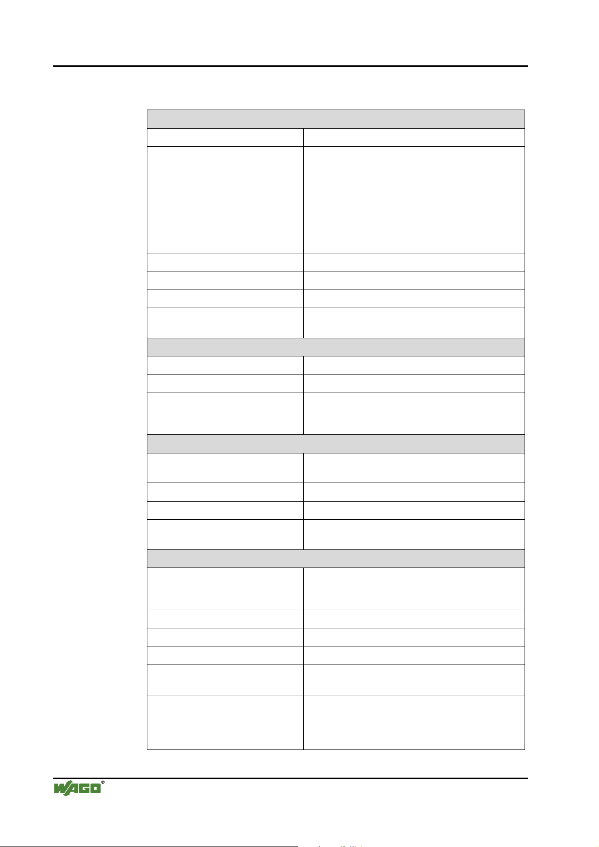
2.2 Technical Data
Mechanic
Material Polycarbonate, Polyamide 6.6
Dimensions W x H* x L
* from upper edge of DIN 35 rail
- Coupler/Controller (Standard)
- Coupler/Controller (ECO)
- Coupler/Controller (FireWire)
- I/O module, single
- I/O module, double
- I/O module, fourfold
- 51 mm x 65 mm x 100 mm
- 50 mm x 65 mm x 100 mm
- 62 mm x 65 mm x 100 mm
- 12 mm x 64 mm x 100 mm
- 24 mm x 64 mm x 100 mm
- 48 mm x 64 mm x 100 mm
Installation on DIN 35 with interlock
Modular by double feather key dovetail
Mounting position any position
Marking standard marking label type
group marking label 8 x 47 mm
Connection
Connection type CAGE CLAMP®
Wire range 0.08 mm² ... 2.5 mm², AWG 28-14
Stripped length 8 … 9 mm,
9 … 10 mm for components with pluggable wiring
(753-xxx)
Contacts
Power jumpers contacts blade/spring contact
self-cleaning
Current via power contacts
Voltage drop at I
< 1 V/64 modules
max
10 A
max
Data contacts slide contact, hard gold plated
1.5 µm, self-cleaning
Climatic environmental conditions
Operating temperature 0 °C ... 55 °C,
-20 °C … +60 °C for components with extended
temperature range (750-xxx/025-xxx)
Storage temperature -20 °C ... +85 °C
Relative humidity 5 % … 95 % without condensation
Resistance to harmful substances acc. to IEC 60068-2-42 and IEC 60068-2-43
Maximum pollutant concentration at
relative humidity < 75%
≤ 25 ppm
SO
2
H
S ≤ 10 ppm
2
Special conditions Ensure that additional measures for components are
taken, which are used in an environment involving:
– dust, caustic vapors or gases
– ionization radiation
WAGO-I/O-SYSTEM 750
BACnet/IP Controller
Page 15
Technical Data • 15
Technical Condition of the Devices
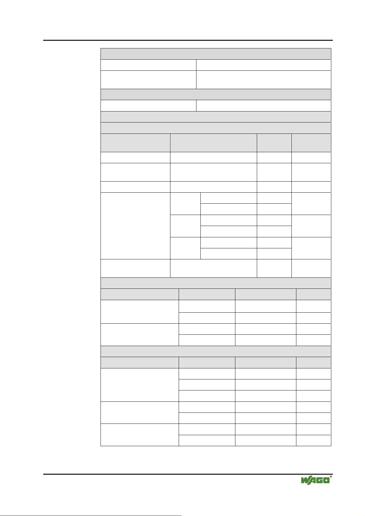
Safe electrical isolation
Air and creepage distance acc. to IEC 60664-1
Degree of pollution
2
acc. To IEC 61131-2
Degree of protection
Degree of protection IP 20
Electromagnetic compatibility
Immunity to interference for industrial areas acc. to EN 61000-6-2 (2001)
Test specification Test values Strength
class
Evaluation
criteria
EN 61000-4-2 ESD 4 kV/8 kV (contact/air) 2/3 B
EN 61000-4-3
10 V/m 80 MHz ... 1 GHz 3 A
electromagnetic fields
EN 61000-4-4 burst 1 kV/2 kV (data/supply) 2/3 B
EN 61000-4-5 surge
-/- (line/line) Data:
B
1 kV (line/earth) 2
ply:
AC supply:
0.5 kV (line/line) 1 DC sup-
0.5 kV (line/earth) 1
1 kV (line/line) 2
2 kV (line/earth) 3
B
B
EN 61000-4-6
RF disturbances
10 V/m 80 % AM
(0.15 ... 80 MHz)
3 A
Emission of interference for industrial areas acc. to EN 61000-6-4 (2001)
Test specification Limit values/[QP]*) Frequency range Distance
79 dB (μV) 150 kHz ... 500 kHz EN 55011 (AC supply,
conducted)
73 dB (μV) 500 kHz ... 30 MHz
40 dB (μV/m) 30 MHz ... 230 MHz 10 m EN 55011 (radiated)
47 dB (μV/m) 230 MHz ... 1 GHz 10 m
Emission of interference for residential areas acc. to EN 61000-6-3 (2001)
Test specification Limit values/[QP]*) Frequency range Distance
EN 55022 (AC supply,
conducted)
66 ... 56 dB (μV) 150 kHz ... 500 kHz
56 dB (μV) 500 kHz ... 5 MHz
60 dB (μV) 5 MHz ... 30 MHz
40 ... 30 dB (μA) 150 kHz ... 500 kHz EN 55022 (DC supply/data,
conducted)
30 dB (μA) 500 kHz ... 30 MHz
30 dB (μV/m) 30 MHz ... 230 MHz 10 m EN 55022 (radiated)
37 dB (μV/m) 230 MHz ... 1 GHz 10 m
WAGO-I/O-SYSTEM 750
BACnet/IP Controller
Page 16
16 • Technical Data
Technical Condition of the Devices
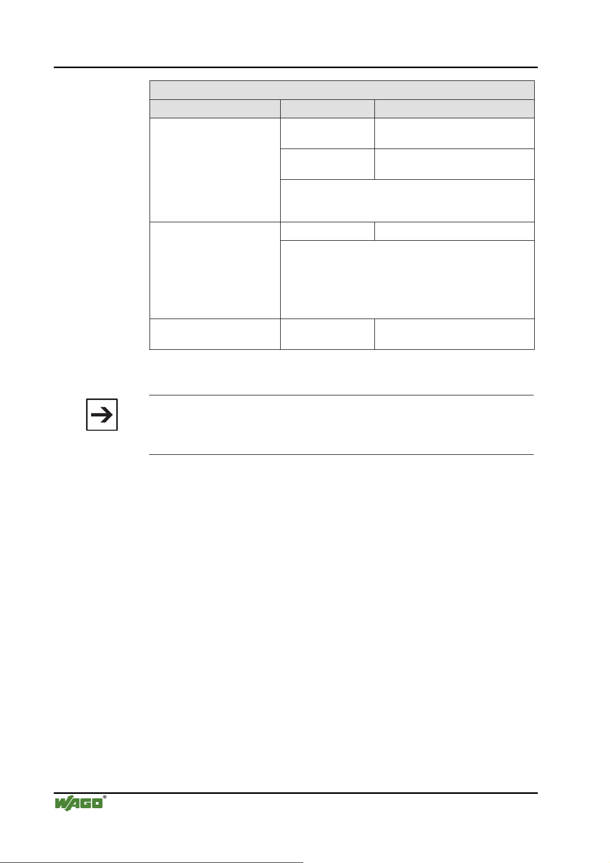
Mechanical strength acc. to IEC 61131-2
Test specification Frequency range Limit value
IEC 60068-2-6 vibration
IEC 60068-2-32 free fall 1 m
*) QP: Quasi Peak
5 Hz ≤ f < 9 Hz
9 Hz ≤ f < 150 Hz
Note on vibration test:
a) Frequency change: max. 1 octave/minute
b) Vibration direction: 3 axes
15 g IEC 60068-2-27 shock
Note on shock test:
a) Type of shock: half sine
b) Shock duration: 11 ms
c) Shock direction: 3x in positive and 3x in negative direction for each of the three mutually perpendicular axes of the
test specimen
1.75 mm amplitude (permanent)
3.5 mm amplitude (short term)
0.5 g (permanent)
1 g (short term)
(module in original packing)
Note
If the technical data of components differ from the values described here, the
technical data shown in the manuals of the respective components shall be
valid.
WAGO-I/O-SYSTEM 750
BACnet/IP Controller
Page 17
Technical Data • 17
Technical Condition of the Devices
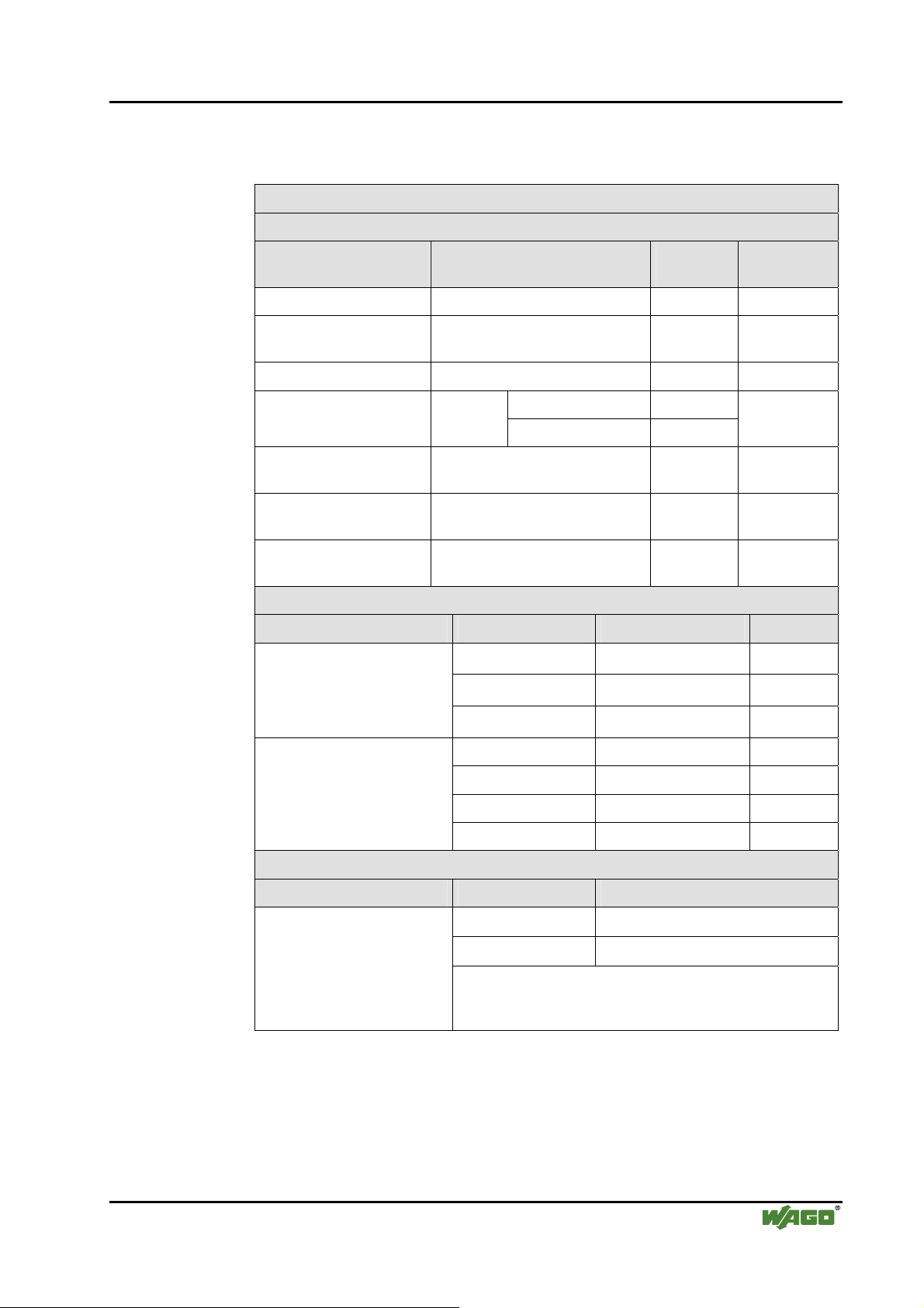
For Products of the WAGO-I/O-SYSTEM 750 with ship specific approvals
supplementary guidelines are valid:
Electromagnetic compatibility
Immunity to interference acc. to Germanischer Lloyd (2003)
Test specification Test values Strength
class
IEC 61000-4-2 ESD 6 kV/8 kV (contact/air) 3/3 B
IEC 61000-4-3
electromagnetic fields
IEC 61000-4-4 burst 1 kV/2 kV (data/supply) 2/3 A
IEC 61000-4-6
RF disturbances
Type test AF disturbances
(harmonic waves)
Type test high voltage 755 V DC
Emission of interference acc. to Germanischer Lloyd (2003)
Test specification Limit values Frequency range Distance
Type test
(EMC1, conducted)
allows for ship bridge control
applications
10 V/m 80 MHz ... 2 GHz 3 A
0.5 kV (line/line) 1 IEC 61000-4-5 surge AC/DC
Supply:
10 V/m 80 % AM
(0.15 ... 80 MHz)
3 V, 2 W - A
1500 V AC
96 ... 50 dB (μV) 10 kHz ... 150 kHz
60 ... 50 dB (μV) 150 kHz ... 350 kHz
50 dB (μV) 350 kHz ... 30 MHz
1 kV (line/earth) 2
3 A
- -
Evaluation
criteria
A
Type test
(EMC1, radiated)
allows for ship bridge control
applications
except: 24 dB (μV/m) 156 MHz ... 165 MHz 3 m
Mechanical strength acc. to Germanischer Lloyd (2003)
Test specification Frequency range Limit value
IEC 60068-2-6 vibration
(category A – D)
80 ... 52 dB (μV/m) 150 kHz ... 300 kHz 3 m
52 ... 34 dB (μV/m) 300 kHz ... 30 MHz 3 m
54 dB (μV/m) 30 MHz ... 2 GHz 3 m
2 Hz ≤ f < 25 Hz
25 Hz ≤ f < 100 Hz
Note on vibration test:
a) Frequency change: max. 1 octave/minute
b) Vibration direction: 3 axes
± 1.6 mm amplitude (permanent)
4 g (permanent)
WAGO-I/O-SYSTEM 750
BACnet/IP Controller
Page 18
18 • Technical Data
Technical Condition of the Devices
Range of
application
Industrial areas EN 61000-6-4 (2001) EN 61000-6-2 (2001)
Residential areas EN 61000-6-3 (2001)*) EN 61000-6-1 (2001)
*)
The system meets the requirements on emission of interference in residential areas with
the field bus coupler/controller for:
ETHERNET
LonWorks
CANopen
DeviceNet
MODBUS
KNX
BACnet
With a special permit, the system can also be implemented with other field bus couplers/controllers in residential areas (housing, commercial and business areas, small-scale
enterprises). The special permit can be obtained from an authority or inspection office. In
Germany, the Federal Office for Post and Telecommunications and its branch offices
issues the permit.
It is possible to use other field bus couplers/controllers under certain boundary conditions. Please contact WAGO Kontakttechnik GmbH & Co. KG.
Required specification
emission of interference
750-342/-841/-842/-860
750-319/-819
750-337/-837
750-306/-806
750-312/-314/ -315/ -316
750-812/-814/ -815/ -816
750-849
750-830
Required specification
immunity to interference
Maximum power dissipation of the components
Bus modules 0.8 W / bus terminal (total power dissipation, sys-
tem/field)
Field bus coupler/controller 2.0 W / coupler/controller
Warning
The power dissipation of all installed components must not exceed the maximum conductible power of the housing (cabinet).
When dimensioning the housing, care is to be taken that even under high external temperatures, the temperature inside the housing does not exceed the
permissible ambient temperature of 55 °C.
WAGO-I/O-SYSTEM 750
BACnet/IP Controller
Page 19
Technical Data • 19
Technical Condition of the Devices
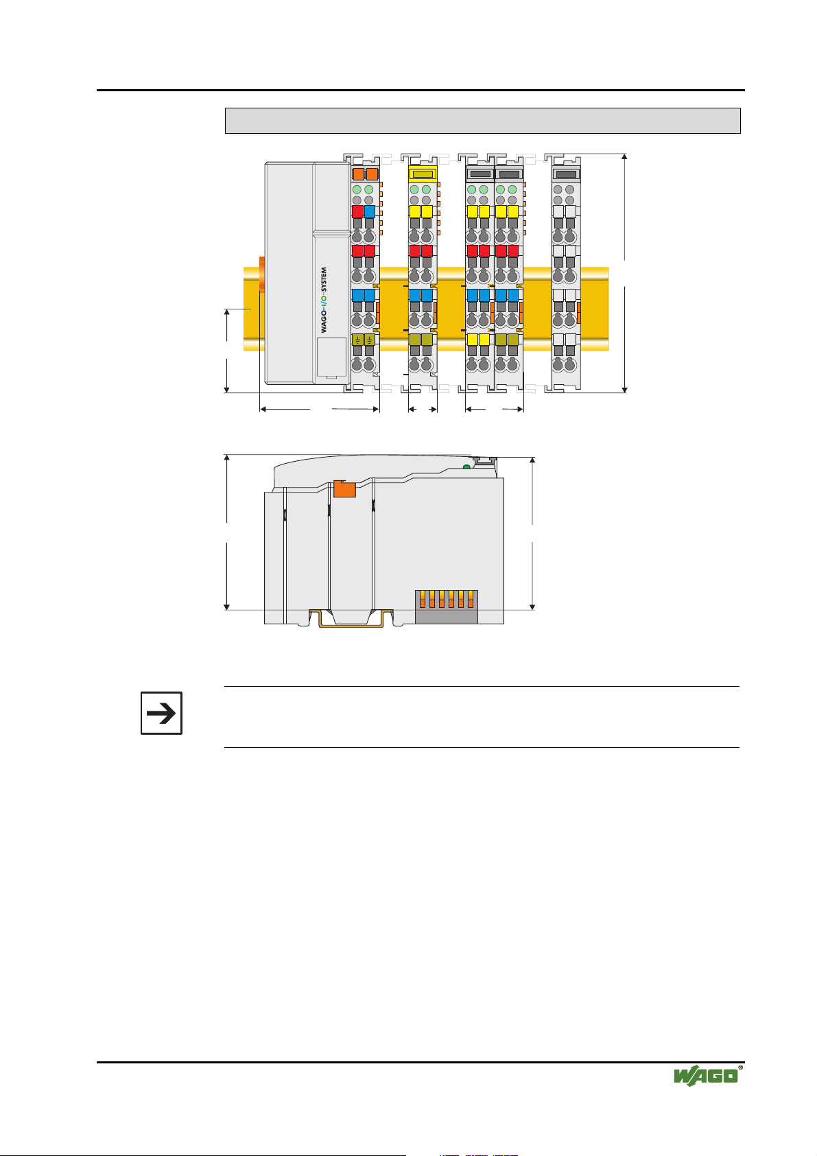
Dimensions
02
01
35
A
B
24V 0V
+
-
A
C
B
D
+
A
C
D
A
C
B
B
D
A
C
D
C
B
D
100
-
51
65
Side view
12
24
Dimensions in mm
64
Fig. 2-2: Dimensions g01xx05e
Note
The illustration shows a standard coupler. For detailed dimensions, please
refer to the technical data of the respective coupler/controller.
WAGO-I/O-SYSTEM 750
BACnet/IP Controller
Page 20
20 • Manufacturing Number
Technical Condition of the Devices
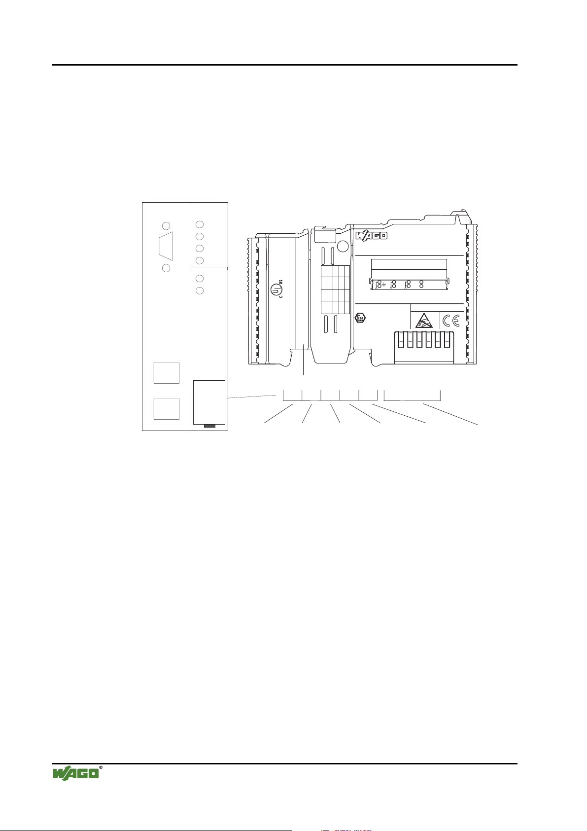
2.3 Manufacturing Number
The manufacturing number indicates the delivery status directly after production.
This number is part of the lateral marking on the component.
In addition, starting from calendar week 43/2000 the manufacturing number is
also printed on the cover of the configuration and programming interface of
the field bus coupler or controller.
PROFIBUS
750-333
ITEM-NO.:750-333
ITEM-NO.:750-333
PROFIBUS DP 12 MBd /DPV1
Hansastr. 27
Hansastr. 27
GL
D-32423 Minden
D-32423 Minden
24V DC
24V DC
AWG 28-14
AWG 28-14
55°C max ambient
55°C max ambient
72072
72072
DS
NO
SW
HW
FWL
II3GD
LISTED 22ZA AND 22XM
LISTED 22ZA AND 22XM
0103000203-B000000
0103000203-B060606
II3GD
DEMKO 02 ATEX132273 X
DEMKO 02 ATEX132273 X
EEx nA II T4
EEx nA II T4
PROFIBUS DP 12 MBd /DPV1
-
Power Supply
Field
24 V
+
0V
0V
Power Supply
Power Supply
Electronic
Electronic
PATENTS PENDING
PATENTS PENDING
WAGO - I/O - SYSTEM
Manufacturing Number
1
0
3
01030002
03-B
060606
72072
Calendar
week
Fig. 2-3: Example: Manufacturing Number of a PROFIBUS field bus coupler 750-333
0
Year Software
version
2
0
0
0
3
-B060606
Hardware
Firmware Loader
version
version
Internal
Number
g01xx15e
0
The manufacturing number consists of the production week and year, the software version (if available), the hardware version of the component, the firmware loader (if available) and further internal information for
WAGO Kontakttechnik GmbH & Co. KG.
WAGO-I/O-SYSTEM 750
BACnet/IP Controller
Page 21

Component Update • 21
Technical Condition of the Devices
2.4 Component Update
For the case of an Update of one component, the lateral marking on each component contains a prepared matrix.
This matrix makes columns available for altogether three updates to the entry
of the current update data, like production order number (NO; starting from
calendar week 13/2004), update date (DS), software version (SW), hardware
version (HW) and the firmware loader version (FWL, if available).
Update Matrix
Current Version data for: 1. Update 2. Update 3. Update
Production Order
Number
Datestamp
Software index
Hardware index
Firmware loader
index
NO
DS
SW
HW
FWL
" only starting from calendar
" only for coupler/controller
If the update of a component took place, the current version data are registered
into the columns of the matrix.
Additionally with the update of a field bus coupler or controller also the cover
of the configuration and programming interface of the coupler or controller is
printed on with the current manufacturing and production order number.
The original manufacturing data on the housing of the component remain
thereby.
2.5 Storage, Assembly and Transport
Wherever possible, the components are to be stored in their original packaging. Likewise, the original packaging provides optimal protection during
transport.
week 13/2004
When assembling or repacking the components, the contacts must not be
soiled or damaged. The components must be stored and transported in appropriate containers/packaging. Thereby, the ESD information is to be regarded.
Statically shielded transport bags with metal coatings are to be used for the
transport of open components for which soiling with amine, amide and silicone has been ruled out, e.g. 3M 1900E.
WAGO-I/O-SYSTEM 750
BACnet/IP Controller
Page 22
22 • Mechanical Setup
Installation Position
2.6 Mechanical Setup
2.6.1 Installation Position
Along with horizontal and vertical installation, all other installation positions
are allowed.
Attention
2.6.2 Total Expansion
In the case of vertical assembly, an end stop has to be mounted as an additional safeguard against slipping.
WAGO item 249-116 End stop for DIN 35 rail, 6 mm wide
WAGO item 249-117 End stop for DIN 35 rail, 10 mm wide
The length of the module assembly (including one end module of 12mm
width) that can be connected to the coupler/controller is 780 mm. When assembled, the I/O modules have a maximum length of 768 mm.
Examples:
• 64 I/O modules of 12 mm width can be connected to one coupler/controller.
• 32 I/O modules of 24 mm width can be connected to one coupler/controller.
Exception:
The number of connected I/O modules also depends on which type of coupler/controller is used. For example, the maximum number of I/O modules
that can be connected to a PROFIBUS coupler/controller is 63 without end
module. The maximum total expansion of a node is calculated as follows:
Warning
The maximum total length of a node without coupler/controller must not exceed 780 mm. Furthermore, restrictions made on certain types of couplers/controllers must be observed (e.g. for PROFIBUS).
WAGO-I/O-SYSTEM 750
BACnet/IP Controller
Page 23

Mechanical Setup • 23
Assembly onto Carrier Rail
2.6.3 Assembly onto Carrier Rail
2.6.3.1 Carrier Rail Properties
All system components can be snapped directly onto a carrier rail in accordance with the European standard EN 50022 (DIN 35).
Warning
WAGO Kontakttechnik GmbH & Co. KG supplies standardized carrier rails
that are optimal for use with the I/O system. If other carrier rails are used,
then a technical inspection and approval of the rail by WAGO Kontakttechnik GmbH & Co. KG should take place.
Carrier rails have different mechanical and electrical properties. For the optimal system setup on a carrier rail, certain guidelines must be observed:
• The material must be non-corrosive.
• Most components have a contact to the carrier rail to ground electro-
magnetic disturbances. In order to avoid corrosion, this tin-plated carrier
rail contact must not form a galvanic cell with the material of the carrier
rail which generates a differential voltage above 0.5 V (saline solution of
0.3% at 20°C) .
• The carrier rail must optimally support the EMC measures integrated into
the system and the shielding of the bus module connections.
• A sufficiently stable carrier rail should be selected and, if necessary, several mounting points (every 20 cm) should be used in order to prevent
bending and twisting (torsion).
• The geometry of the carrier rail must not be altered in order to secure the
safe hold of the components. In particular, when shortening or mounting
the carrier rail, it must not be crushed or bent.
• The base of the I/O components extends into the profile of the carrier rail.
For carrier rails with a height of 7.5 mm, mounting points are to be riveted
under the node in the carrier rail (slotted head captive screws or blind rivets).
WAGO-I/O-SYSTEM 750
BACnet/IP Controller
Page 24
24 • Mechanical Setup
Spacing
2.6.3.2 WAGO DIN Rail
WAGO carrier rails meet the electrical and mechanical requirements.
Item Number Description
210-113 /-112 35 x 7.5; 1 mm; steel yellow chromated; slotted/unslotted
210-114 /-197 35 x 15; 1.5 mm; steel yellow chromated; slotted/unslotted
210-118 35 x 15; 2.3 mm; steel yellow chromated; unslotted
210-198 35 x 15; 2.3 mm; copper; unslotted
210-196 35 x 7.5; 1 mm; aluminum; unslotted
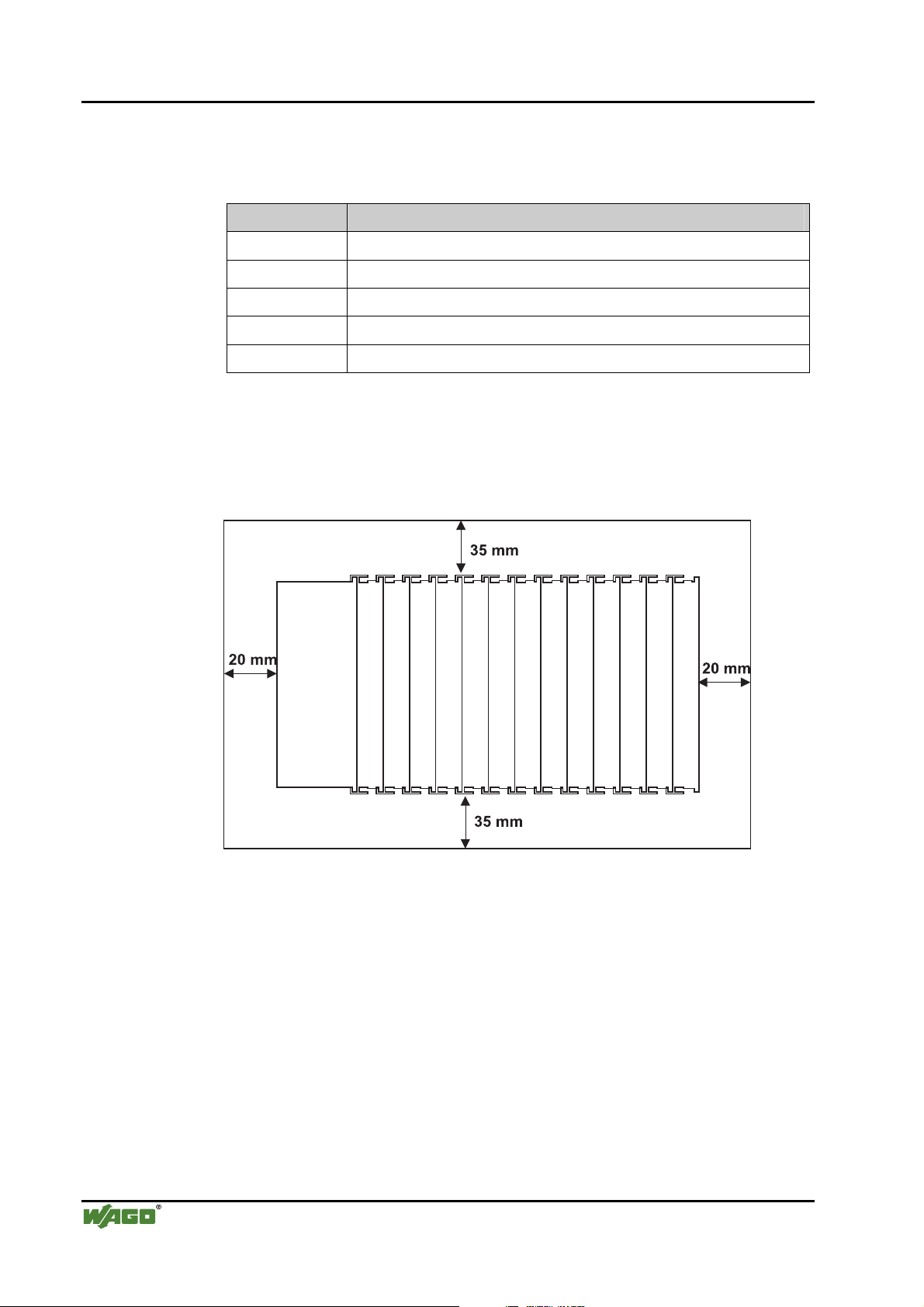
2.6.4 Spacing
The spacing between adjacent components, cable conduits, casing and frame
sides must be maintained for the complete field bus node.
Fig. 2-4: Spacing g01xx13x
The spacing creates room for heat transfer, installation or wiring. The spacing
to cable conduits also prevents conducted electromagnetic interferences from
influencing the operation.
WAGO-I/O-SYSTEM 750
BACnet/IP Controller
Page 25
Mechanical Setup • 25
Plugging and Removal of the Components
2.6.5 Plugging and Removal of the Components
Warning
Before work is done on the components, the voltage supply must be turned off.
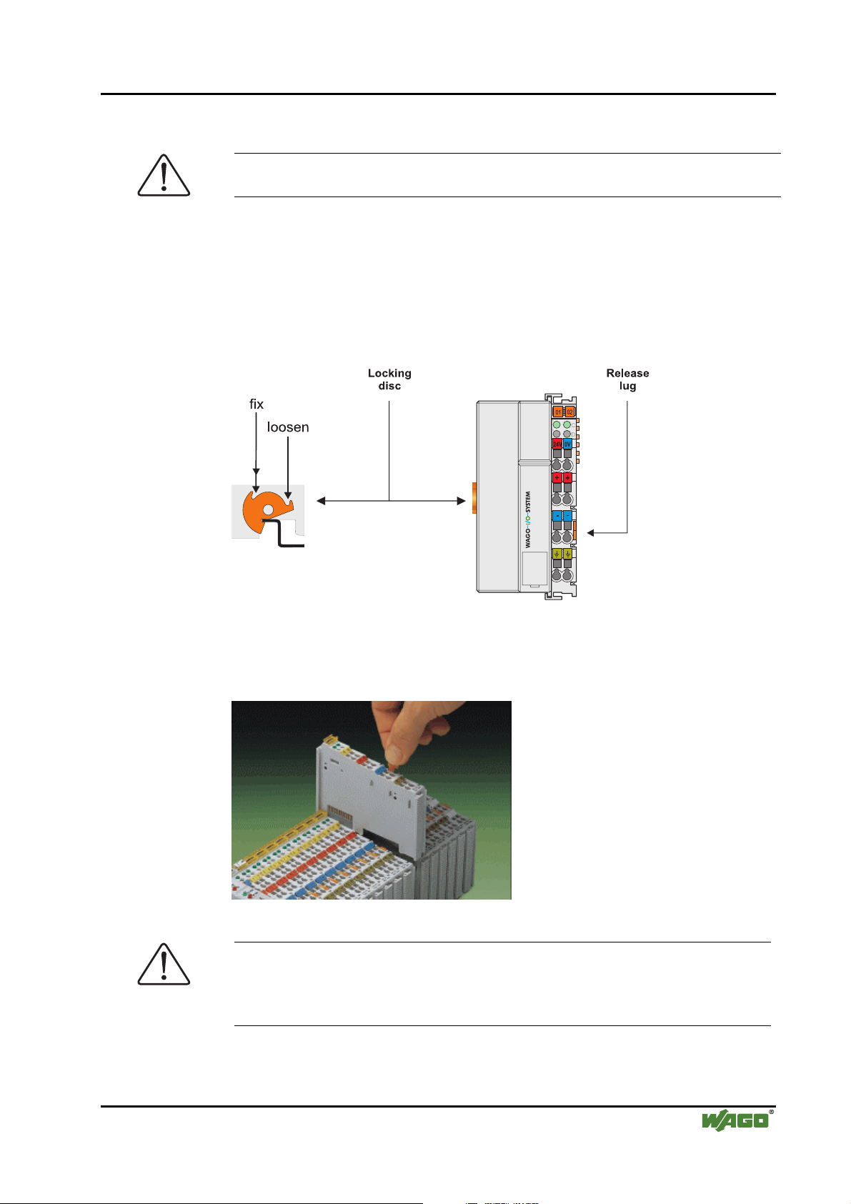
In order to safeguard the coupler/controller from jamming, it should be fixed
onto the carrier rail with the locking disc To do so, push on the upper groove
of the locking disc using a screwdriver.
To pull out the field bus coupler/controller, release the locking disc by pressing on the bottom groove with a screwdriver and then pulling the orange colored unlocking lug .
Fig. 2-5: Coupler/Controller and unlocking lug g01xx12e
It is also possible to release an individual I/O module from the unit by pulling
an unlocking lug.
Fig. 2-6: removing bus terminal p0xxx01x
Danger
Ensure that an interruption of the PE will not result in a condition which
could endanger a person or equipment!
For planning the ring feeding of the ground wire, please see chapter 2.6.3.
WAGO-I/O-SYSTEM 750
BACnet/IP Controller
Page 26
26 • Mechanical Setup
Assembly Sequence
2.6.6 Assembly Sequence
All system components can be snapped directly on a carrier rail in accordance
with the European standard EN 50022 (DIN 35).
The reliable positioning and connection is made using a tongue and groove
system. Due to the automatic locking, the individual components are securely
seated on the rail after installing.
Starting with the coupler/controller, the bus modules are assembled adjacent
to each other according to the project planning. Errors in the planning of the
node in terms of the potential groups (connection via the power contacts) are
recognized, as the bus modules with power contacts (male contacts) cannot be
linked to bus modules with fewer power contacts.
Attention
Always link the bus modules with the coupler/controller, and always plug
from above.
Warning
Never plug bus modules from the direction of the end terminal. A ground
wire power contact, which is inserted into a terminal without contacts, e.g. a
4-channel digital input module, has a decreased air and creepage distance to
the neighboring contact in the example DI4.
Always terminate the field bus node with an end module (750-600).
WAGO-I/O-SYSTEM 750
BACnet/IP Controller
Page 27

Mechanical Setup • 27
Internal Bus/Data Contacts
2.6.7 Internal Bus/Data Contacts
Communication between the coupler/controller and the bus modules as well as
the system supply of the bus modules is carried out via the internal bus. It is
comprised of 6 data contacts, which are available as self-cleaning gold spring
contacts.
Fig. 2-7: Data contacts p0xxx07x
Warning
Do not touch the gold spring contacts on the I/O modules in order to avoid
soiling or scratching!
ESD (Electrostatic Discharge)
The modules are equipped with electronic components that may be destroyed
by electrostatic discharge. When handling the modules, ensure that the environment (persons, workplace and packing) is well grounded. Avoid touching
conductive components, e.g. data contacts.
WAGO-I/O-SYSTEM 750
BACnet/IP Controller
Page 28
28 • Mechanical Setup
Power Contacts
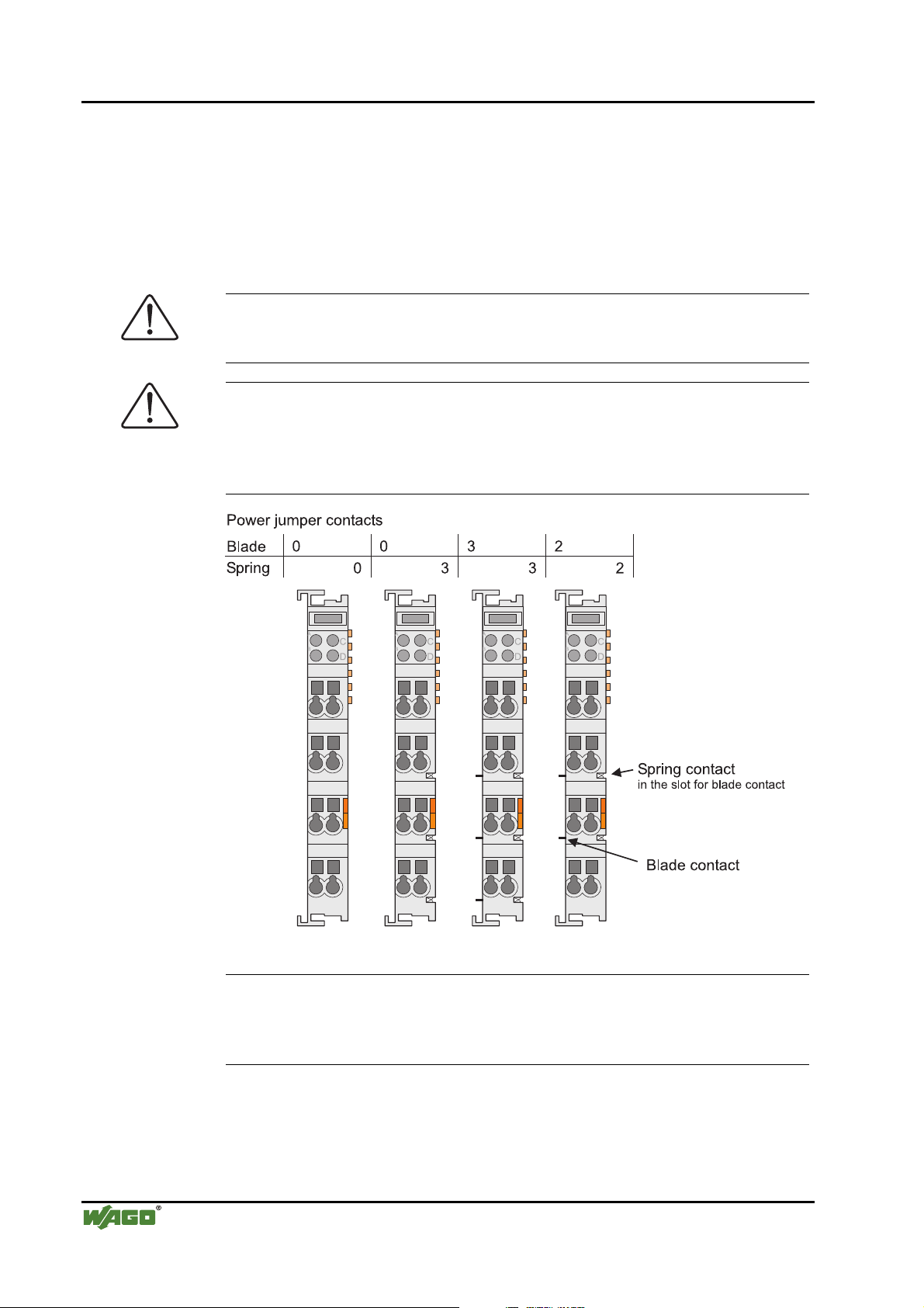
2.6.8 Power Contacts
Self-cleaning power contacts , are situated on the side of the components
which further conduct the supply voltage for the field side. These contacts
come as touchproof spring contacts on the right side of the coupler/controller
and the bus module. As fitting counterparts the module has male contacts on
the left side.
Danger
The male contacts are sharp-edged. Handle the module carefully to prevent
injury.
Attention
Please take into consideration that some bus modules have no or only a few
power jumper contacts. The design of some modules does not allow them to
be physically assembled in rows, as the grooves for the male contacts are
closed at the top.
WAGO-I/O-SYSTEM 750
Fig. 2-8: Example for the arrangement of power contacts g0xxx05e
Recommendation
With the WAGO ProServe® Software smartDESIGNER, the structure of a
field bus node can be configured. The configuration can be tested via the integrated accuracy check.
BACnet/IP Controller
Page 29
Mechanical Setup • 29
Wire Connection
2.6.9 Wire Connection
All components have CAGE CLAMP® connections.
The WAGO CAGE CLAMP® connection is appropriate for solid, stranded
and finely stranded conductors. Each clamping unit accommodates one conductor.
Fig. 2-9: CAGE CLAMP® Connection g0xxx08x
The operating tool is inserted into the opening above the connection. This
opens the CAGE CLAMP®. Subsequently the conductor can be inserted into
the opening. After removing the operating tool, the conductor is safely
clamped.
More than one conductor per connection is not permissible. If several conductors have to be made at one connection point, then they should be made away
from the connection point using WAGO Terminal Blocks. The terminal blocks
may be jumpered together and a single wire brought back to the I/O module
connection point.
Attention
If it is unavoidable to jointly connect 2 conductors, then a ferrule must be used
to join the wires together.
Ferrule:
Length 8 mm
Nominal cross section
1 mm2 for 2 conductors with 0.5 mm2 each
max.
WAGO Product 216-103 or products with comparable properties
WAGO-I/O-SYSTEM 750
BACnet/IP Controller
Page 30
30 • Power Supply
Isolation
2.7 Power Supply
2.7.1 Isolation
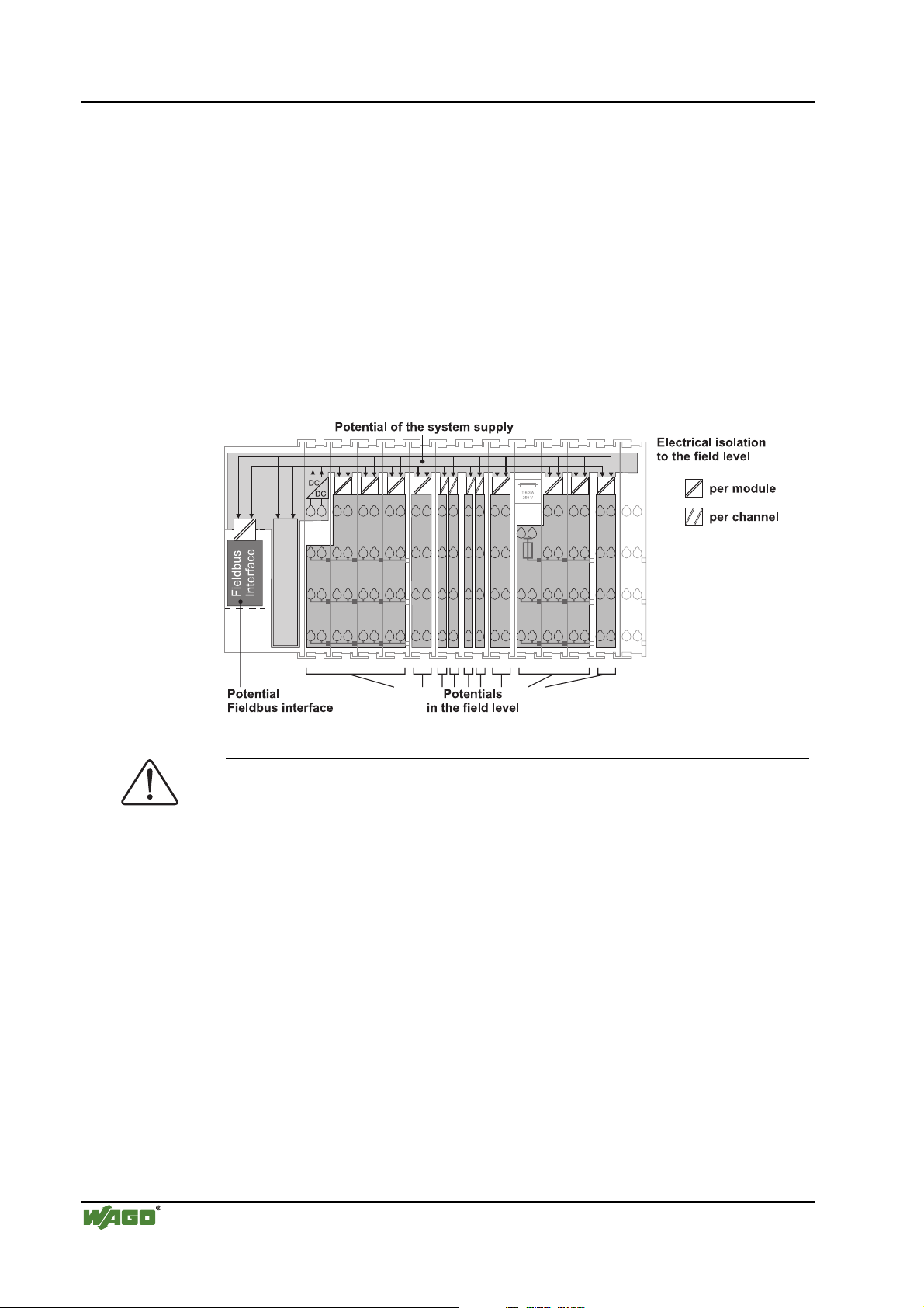
Within the field bus node, there are three electrically isolated potentials.
• Operational voltage for the field bus interface.
• Electronics of the couplers/controllers and the bus modules (internal bus).
• All bus modules have an electrical isolation between the electronics (inter-
nal bus, logic) and the field electronics. Some digital and analog input
modules have each channel electrically isolated, please see catalog.
Fig. 2-10: Isolation g0xxx01e
Attention
The ground wire connection must be present in each group. In order that all
protective conductor functions are maintained under all circumstances, it is
recommended that a ground wire be connected at the beginning and end of a
potential group. (ring format, please see chapter 2.8.3). Thus, if a bus module
comes loose from a composite during servicing, then the protective conductor
connection is still guaranteed for all connected field devices.
When using a joint power supply unit for the 24 V system supply and the
24 V field supply, the electrical isolation between the internal bus and the
field level is eliminated for the potential group.
WAGO-I/O-SYSTEM 750
BACnet/IP Controller
Page 31

Power Supply • 31
System Supply
2.7.2 System Supply
2.7.2.1 Connection
The WAGO-I/O-SYSTEM 750 requires a 24 V direct current system supply
(-15 % or +20 %). The power supply is provided via the coupler/controller
and, if necessary, in addition via the internal system supply modules
(750-613). The voltage supply is reverse voltage protected.
Attention
The use of an incorrect supply voltage or frequency can cause severe damage
to the component.
Fig. 2-11: System Supply g0xxx02e
The direct current supplies all internal system components, e.g. coupler/controller electronics, field bus interface and bus modules via the internal
bus (5 V system voltage). The 5 V system voltage is electrically connected to
the 24 V system supply.
Fig. 2-12: System Voltage g0xxx06e
WAGO-I/O-SYSTEM 750
BACnet/IP Controller
Page 32

32 • Power Supply
f
System Supply
Attention
Resetting the system by switching on and off the system supply, must take
place simultaneously for all supply modules (coupler/controller and
750-613).
2.7.2.2 Alignment
Recommendation
A stable network supply cannot be taken for granted always and everywhere.
Therefore, regulated power supply units should be used in order to guarantee
the quality of the supply voltage.
The supply capacity of the coupler/controller or the internal system supply
module (750-613) can be taken from the technical data of the components.
Internal current consumption*)
Residual current for bus terminals*)
*)
cf. catalogue W4 Volume 3, manuals or internet
Example Coupler 750-301:
Current consumption via system voltage:
5 V for electronics of the bus modules and coupler/controller
Available current for the bus modules. Provided by
the bus power supply unit. See coupler/controller
and internal system supply module (750-613)
internal current consumption:350 mA at 5 V
residual current for
bus modules : 1650 mA at 5 V
sum I
: 2000 mA at 5 V
(5V) total
The internal current consumption is indicated in the technical data for each
bus terminal. In order to determine the overall requirement, add together the
values of all bus modules in the node.
WAGO-I/O-SYSTEM 750
Attention
If the sum of the internal current consumption exceeds the residual current
or bus modules, then an internal system supply module (750-613) must be
placed before the module where the permissible residual current was exceeded.
BACnet/IP Controller
Page 33

Power Supply • 33
System Supply
Example:
A node with a PROFIBUS Coupler 750-333 consists of 20 relay modules (750-517) and 10 digital input modules (750-405).
Current consumption:
20* 90 mA = 1800 mA
10* 2 mA = 20 mA
Sum 1820 mA
The coupler can provide 1650 mA for the bus modules. Consequently,
an internal system supply module (750-613), e.g. in the middle of the
node, should be added.
Recommendation
With the WAGO ProServe® Software smartDESIGNER, the assembly of a
field bus node can be configured. The configuration can be tested via the integrated accuracy check.
The maximum input current of the 24 V system supply is 500 mA. The exact
electrical consumption (I
Coupler/Controller
I
= Sum of all the internal current consumption of the connected
(5 V) total
) can be determined with the following formulas:
(24 V)
bus modules
+ internal current consumption coupler/controller
750-613
I
= Sum of all the internal current consumption of the connected
(5 V) total
bus modules
Input current I
(24 V)
=
5 V / 24 V * I
η
= 0.87 (at nominal load)
(5 V) total
/ η
Attention
If the electrical consumption of the power supply point for the 24 V-system
supply exceeds 500 mA, then the cause may be an improperly aligned node
or a defect.
During the test, all outputs, in particular those of the relay modules, must be
active.
WAGO-I/O-SYSTEM 750
BACnet/IP Controller
Page 34

34 • Power Supply
Field Supply
2.7.3 Field Supply
2.7.3.1 Connection
Sensors and actuators can be directly connected to the relevant channel of the
bus module in 1/4 conductor connection technology. The bus module supplies
power to the sensors and actuators. The input and output drivers of some bus
modules require the field side supply voltage.
The coupler/controller provides field side power (DC 24V). In this case it is a
passive power supply without protection equipment.
Power supply modules are available for other potentials, e. g. AC 230 V. Likewise, with the aid of the power supply modules, various potentials can be set
up. The connections are linked in pairs with a power contact.
Fig. 2-13: Field Supply (Sensor/Actuator) g0xxx03e
The supply voltage for the field side is automatically passed to the next module via the power jumper contacts when assembling the bus modules .
The current load of the power contacts must not exceed 10 A on a continual
basis. The current load capacity between two connection terminals is identical
to the load capacity of the connection wires.
By inserting an additional power supply module, the field supply via the
power contacts is disrupted. From there a new power supply occurs which
may also contain a new voltage potential.
WAGO-I/O-SYSTEM 750
BACnet/IP Controller
Page 35

Power Supply • 35
Field Supply
Attention
Some bus modules have no or very few power contacts (depending on the I/O
function). Due to this, the passing through of the relevant potential is disrupted. If a field supply is required for subsequent bus modules, then a power
supply module must be used.
Note the data sheets of the bus modules.
In the case of a node setup with different potentials, e.g. the alteration from
DC 24 V to AC 230V, a spacer module should be used. The optical separation of the potentials acts as a warning to heed caution in the case of wiring
and maintenance works. Thus, the results of wiring errors can be prevented.
2.7.3.2 Fusing
Internal fusing of the field supply is possible for various field voltages via an
appropriate power supply module.
750-601 24 V DC, Supply/Fuse
750-609 230 V AC, Supply/Fuse
750-615 120 V AC, Supply/Fuse
750-610 24 V DC, Supply/Fuse/Diagnosis
750-611 230 V AC, Supply/Fuse/Diagnosis
Fig. 2-14: Supply module with fuse carrier (Example 750-610) g0xxx09x
WAGO-I/O-SYSTEM 750
BACnet/IP Controller
Page 36

36 • Power Supply
Field Supply
Warning
In the case of power supply modules with fuse holders, only fuses with a
maximum dissipation of 1.6 W (IEC 127) must be used.
For UL approved systems only use UL approved fuses.
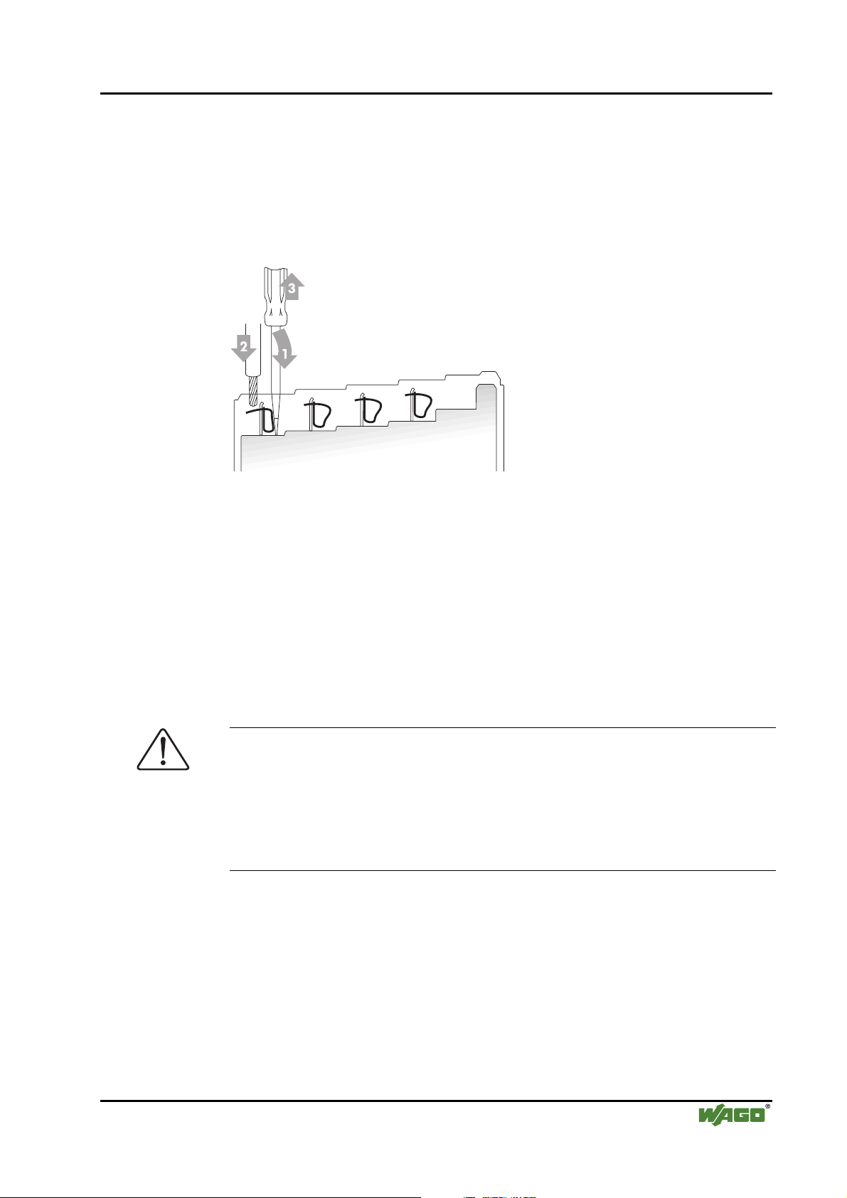
In order to insert or change a fuse, or to switch off the voltage in succeeding
bus modules, the fuse holder may be pulled out. In order to do this, use a
screwdriver for example, to reach into one of the slits (one on both sides) and
pull out the holder.
Fig. 2-15: Removing the fuse carrier p0xxx05x
Lifting the cover to the side opens the fuse carrier.
Fig. 2-16: Opening the fuse carrier p0xxx03x
Fig. 2-17: Change fuse p0xxx04x
After changing the fuse, the fuse carrier is pushed back into its original position.
WAGO-I/O-SYSTEM 750
BACnet/IP Controller
Page 37

Power Supply • 37
Field Supply
Alternatively, fusing can be done externally. The fuse modules of the WAGO
series 281 and 282 are suitable for this purpose.
Fig. 2-18: Fuse modules for automotive fuses, series 282 pf66800x
Abb. 2-19: Fuse modules for automotive fuses, series 2006 p0xxx13x
Fig. 2-20: Fuse modules with pivotable fuse carrier, series 281 pe61100x
Abb. 2-21: Fuse modules with pivotable fuse carrier, series 2002 p0xxx12x
WAGO-I/O-SYSTEM 750
BACnet/IP Controller
Page 38

38 • Power Supply
Supplementary Power Supply Regulations
2.7.4 Supplementary Power Supply Regulations
The WAGO-I/O-SYSTEM 750 can also be used in shipbuilding or offshore
and onshore areas of work (e. g. working platforms, loading plants). This is
demonstrated by complying with the standards of influential classification
companies such as Germanischer Lloyd and Lloyds Register.
Filter modules for 24-volt supply are required for the certified operation of the
system.
Item No. Name Description
750-626 Supply filter Filter module for system supply and field supply (24 V, 0 V), i.e.
for field bus coupler/controller and bus power supply (750-613)
750-624 Supply filter Filter module for the 24 V- field supply
(750-602, 750-601, 750-610)
Therefore, the following power supply concept must be absolutely complied
with.
WAGO-I/O-SYSTEM 750
Fig. 2-22: Power supply concept g01xx11e
Note
Another potential power terminal 750-601/602/610 must only be used behind
the filter terminal 750-626 if the protective earth conductor is needed on the
lower power contact or if a fuse protection is required.
BACnet/IP Controller
Page 39

Power Supply • 39
Supply Example
2.7.5 Supply Example
Attention
The system supply and the field supply should be separated in order to ensure
bus operation in the event of a short-circuit on the actuator side.
L1
L2
L3
N
PE
a)
1)
b)
c)
1)
d)
System
Supply
Field
Supply
Field
Supply
230V
230V
24V
24V
10 A
750-613
2) 2)
10 A
750-512 750-512750-616 750-513 750-610 750-552 750-600750-612 750-616
750-630750-400 750-410 750-401
Shield (screen) bus
Main ground bus
1) Separation module
recommended
2) Ring-feeding
recommended
a) Power Supply
on coupler / controller
via external Supply
Module
b) Internal System
Supply Module
c) Supply Module
passive
d)
Supply Module
with fuse carrier/
iagnostics
d
Fig. 2-23: Supply example g0xxx04e
WAGO-I/O-SYSTEM 750
BACnet/IP Controller
Page 40

40 • Power Supply
Power Supply Unit
2.7.6 Power Supply Unit
The WAGO-I/O-SYSTEM 750 requires a 24 V direct current system supply
with a maximum deviation of -15 % or +20 %.
Recommendation
A stable network supply cannot be taken for granted always and everywhere.
Therefore, regulated power supply units should be used in order to guarantee
the quality of the supply voltage.
A buffer (200 µF per 1 A current load) should be provided for brief voltage
dips. The I/O system buffers for approx 1 ms.
The electrical requirement for the field supply is to be determined individually
for each power supply point. Thereby all loads through the field devices and
bus modules should be considered. The field supply as well influences the bus
modules, as the inputs and outputs of some bus modules require the voltage of
the field supply.
Attention
The system supply and the field supply should be isolated from the power
supplies in order to ensure bus operation in the event of short circuits on the
actuator side.
WAGO products
Item No.
Description
787-612 Primary switched mode; DC 24 V; 2,5 A
Input nominal voltage AC 230 V
787-622 Primary switched mode; DC 24 V; 5 A
Input nominal voltage AC 230 V
787-632 Primary switched mode; DC 24 V; 10 A
Input nominal voltage AC 230/115 V
288-809
288-810
288-812
288-813
Rail-mounted modules with universal mounting carrier
AC 115 V / DC 24 V; 0,5 A
AC 230 V / DC 24 V; 0,5 A
AC 230 V / DC 24 V; 2 A
AC 115 V / DC 24 V; 2 A
WAGO-I/O-SYSTEM 750
BACnet/IP Controller
Page 41

Grounding • 41
Grounding the DIN Rail
2.8 Grounding
2.8.1 Grounding the DIN Rail
2.8.1.1 Framework Assembly
When setting up the framework, the carrier rail must be screwed together with
the electrically conducting cabinet or housing frame. The framework or the
housing must be grounded. The electronic connection is established via the
screw. Thus, the carrier rail is grounded.
Attention
2.8.1.2 Insulated Assembly
Care must be taken to ensure the flawless electrical connection between the
carrier rail and the frame or housing in order to guarantee sufficient grounding.
Insulated assembly has been achieved when there is constructively no direct
conduction connection between the cabinet frame or machine parts and the
carrier rail. Here the earth must be set up via an electrical conductor.
The connected grounding conductor should have a cross section of at least
4 mm2.
Recommendation
The optimal insulated setup is a metallic assembly plate with grounding connection with an electrical conductive link with the carrier rail.
The separate grounding of the carrier rail can be easily set up with the aid of
the WAGO ground wire terminals.
Item No. Description
283-609 1-conductor ground (earth) terminal block make an automatic contact to
the carrier rail; conductor cross section: 0.2 -16 mm
Note: Also order the end and intermediate plate (283-320).
2
WAGO-I/O-SYSTEM 750
BACnet/IP Controller
Page 42

42 • Grounding
Grounding Function
2.8.2 Grounding Function
The grounding function increases the resistance against disturbances from
electro-magnetic interferences. Some components in the I/O system have a
carrier rail contact that dissipates electro-magnetic disturbances to the carrier
rail.
Fig. 2-24: Carrier rail contact g0 xxx10e
Attention
Care must be taken to ensure the direct electrical connection between the
carrier rail contact and the carrier rail.
The carrier rail must be grounded.
For information on carrier rail properties, please see chapter 2.6.3.2.
WAGO-I/O-SYSTEM 750
BACnet/IP Controller
Page 43

Grounding • 43
Grounding Protection
2.8.3 Grounding Protection
For the field side, the ground wire is connected to the lowest connection terminals of the power supply module. The ground connection is then connected
to the next module via the Power Jumper Contact (PJC). If the bus module has
the lower power jumper contact, then the ground wire connection of the field
devices can be directly connected to the lower connection terminals of the bus
module.
Attention
Should the ground conductor connection of the power jumper contacts within
the node become disrupted, e. g. due to a 4-channel bus terminal, the ground
connection will need to be re-established.
The ring feeding of the grounding potential will increase the system safety.
When one bus module is removed from the group, the grounding connection
will remain intact.
The ring feeding method has the grounding conductor connected to the beginning and end of each potential group.
Fig. 2-25: Ring-feeding g0 xxx07e
Attention
The regulations relating to the place of assembly as well as the national regulations for maintenance and inspection of the grounding protection must be
observed.
WAGO-I/O-SYSTEM 750
BACnet/IP Controller
Page 44

44 • Shielding (Screening)
General
2.9 Shielding (Screening)
2.9.1 General
The shielding of the data and signal conductors reduces electromagnetic interferences thereby increasing the signal quality. Measurement errors, data transmission errors and even disturbances caused by overvoltage can be avoided.
Attention
Constant shielding is absolutely required in order to ensure the technical
specifications in terms of the measurement accuracy.
The data and signal conductors should be separated from all high-voltage
cables.
The cable shield should be potential. With this, incoming disturbances can be
easily diverted.
The shielding should be placed over the entrance of the cabinet or housing in
order to already repel disturbances at the entrance.
2.9.2 Bus Conductors
The shielding of the bus conductor is described in the relevant assembly
guidelines and standards of the bus system.
2.9.3 Signal Conductors
Bus modules for most analog signals along with many of the interface bus
modules include a connection for the shield.
Note
For a better shield performance, the shield should have previously been
placed over a large area. The WAGO shield connection system is suggested
for such an application.
This suggestion is especially applicable if the equipment can have even current or high impulse formed currents running through (for example initiated
by atmospheric discharge).
WAGO-I/O-SYSTEM 750
BACnet/IP Controller
Page 45

Assembly Guidelines/Standards • 45
WAGO Shield (Screen) Connecting System
2.9.4 WAGO Shield (Screen) Connecting System
The WAGO Shield Connecting system includes a shield clamping saddle, a
collection of rails and a variety of mounting feet. Together these allow many
different possibilities. See catalog W4 volume 3 chapter 10.
Fig. 2-26: WAGO Shield (Screen) Connecting System p0xxx08x, p0xxx09x, and p0xxx10x
Fig. 2-27: Application of the WAGO Shield (Screen) Connecting System p0xxx11x
2.10 Assembly Guidelines/Standards
DIN 60204, Electrical equipping of machines
DIN EN 50178 Equipping of high-voltage systems with electronic
components (replacement for VDE 0160)
WAGO-I/O-SYSTEM 750
BACnet/IP Controller
Page 46

46 • BACnet/IP Controller 750-830
Description
3 Fieldbus Controller
3.1 BACnet/IP Controller 750-830
3.1.1 Description
The 750-830 BACnet Controller connects the WAGO-I/O-SYSTEM with the
BACnet protocol. The 750-830 Controller complies with the BACnet device
profile "BACnet Building Controller" B-BC in accordance with DIN EN ISO
16484-5 and has 3 functions available internally:
1. Native server: For each channel, appropriate BACnet objects are gen-
erated automatically for the digital, analog input and output modules
that are connected to the controller.
2. Application server: Other supported BACnet objects can be created
via the IEC 61131-3 programming environment.
3. Application client: Using the client functionality, objects and their
properties can be accessed by other BACnet devices.
Access to BACnet/IP networks is provided by the controller's RJ45 interface.
The RS232 interface can be used as a standard RS232 or (beginning with
software version 2) as a BACnet-PTP connection to other PTP-capable
BACnet devices.
The 750-830 BACnet/IP Controller is based on an ETHERNET controller and
supports the corresponding functions:
All input signals from the sensors are combined. After connecting the controller, all of the I/O modules on the node are determined and a local process image is created from these. Analog and specialty module data is sent via words
and/or bytes; digital data is sent bit by bit.
The local process image is divided into two data zones containing input and
output data areas. The data of the analog modules are written into the process
image in the order of their position after the controller.
The bits of the digital modules are combined into words and then also mapped
onto the analog modules in the process image. If the number of digital inputs
and outputs is greater than 16 bits, the controller automatically begins a new
word.
According to IEC -61131-3 programming, the processing of the process data
occurs on location in the PFC. The link results created by this can be output
directly to the actors or transmitted via the bus to the higher-order controller.
The controller can then optionally communicate with higher-order systems either via 10/100 Mbit/s (ETHERNET), "100BaseTX" or "10BaseT".
WAGO-I/O-SYSTEM 750
BACnet/IP Controller
Page 47

BACnet/IP Controller 750-830 • 47
Compatibility
An application program can be created using the WAGO-I/O-PRO CAA software, based on IEC 61131-3. The controller provides 512 KB of program
memory, 256 KB of data memory and 24 KB of retain memory for this purpose. Start-up and configuration of the BACnet/IP Controller is performed using the Windows-compliant WAGO BACnet Configurator.
For communication via BACnet, the BACnet/IP and BACnet/PTP protocols
are supported. Process data are also sent via MODBUS/TCP(UDP). HTTP,
BootP, DHCP, DNS, SNTP, FTP, SNMP V1 and SMTP are used for administration and diagnosis.
The programmer can program clients and servers via an internal socket-API
for all transport protocols (TCP, UDP, etc.) with functional modules. Library
functions are available for function expansion. With the IEC 61131-3 library
"SysLibRTC.lib," for example, a buffered real time clock with date, time
(resolution 1 second), alarm functions, and a timer is incorporated. This clock
is supplied with auxiliary power during a power failure.
This controller is based on a 32-Bit CPU with multitasking capabilities, i.e.
several programs can be executed semi-simultaneously.
An internal server is available for Web-based applications.
Information on configuration is also stored as HTML pages in the fieldbus
controller and can be read using a customary web browser (web-based Management-System). In addition, internal HTML pages can also be stored using
an implemented file system.
3.1.2 Compatibility
Additional Information
To get the current software version for programming and configuring the
Controller 750-830, go to our website at http://www.wago.com ! Service !
Documentation ! WAGO-I/O-SYSTEM759 ! WAGO-I/O-PRO
Additional Information
You can find the BACnet Configurator on the internet on the website
http://www.wago.com Service ! Downloads ! Building Automation !
BACnet Downloads.
The documentation for the BACnet Configurator can be found under Service
! Documentation ! WAGO-I/O-SYSTEM 750 ! Fieldbus Coupler and
Programmable Fieldbus Controller ! 750-830.
WAGO-I/O-SYSTEM 750
BACnet/IP Controller
Page 48

48 • BACnet/IP Controller 750-830
Hardware
3.1.3 Hardware
3.1.3.1 View
BACnet/IP
fieldbus
connection
RJ45
fieldbus
connection
RS232
service interface
as a configuration and
programming interface
(flap open)
LINK
ACT
BT
MS
NS
I/O
USR
A
B
0
50-83
7
01
24V 0V
++
_
_
02
C
D
mode switch
power supply status
- system
- power contacts
data contacts
24V
bus coupler power supply
0V
24V
power contacts supply
0V
power contacts
Fig. 3-1: BACnet/IP Controller G083000e
The controller in detail:
• A power supply unit for the system supply and power jumper contacts for
the field supply via bus modules.
• Two fieldbus connections (RJ45 and RS232)
• LEDs as status display of the operation, the bus communication, the oper-
ating voltages as well as for error messages and diagnostics
• Service interface, alternative for programming and configuration (see
3.1.3.5)
• Operating mode switch (see
3.1.3.6)
WAGO-I/O-SYSTEM 750
BACnet/IP Controller
Page 49

BACnet/IP Controller 750-830 • 49
Hardware
3.1.3.2 Power Supply
The power supply is derived from modules with CAGE CLAMP® connections. 24 V power supply (see Fig. 3-1) for system power and power to the
field side.
The integrated power supply provides the required power to the electronics
and the bus modules.
An electrically isolated power supply is provided to the fieldbus interface.
DC
DC
1
5
24V/0V
2
6
24 V
24 V
0V
10 nF
DC
DC
I/O
MODULES
24 V
3
7
ELECTRONIC
FiELDBUS
INTERFACE
FiELDBUS INTERFACE
ELECTRONIC
750-830
0V
4
8
0V
10 nF
Fig. 3-1: Power Supply G083001e
WAGO-I/O-SYSTEM 750
BACnet/IP Controller
Page 50

50 • BACnet/IP Controller 750-830
Hardware
3.1.3.3 Fieldbus Connection
The connection to the fieldbus is made via an RJ45 connector, which is also
called a "Western plug." Wiring for the RJ45 socket on the fieldbus controller
adheres to 100BaseTX specifications. It is mandatory to use a twisted pair cable of category 5 as a connecting cable. Cable types S-UTP (Screened Unshielded Twisted Pair) and STP (Shielded Twisted Pair) with a maximum
segment length of 100 m can be used.
Tab. 3-1: Plug-in Contacts
Contact Signal
8
7
6
5
4
3
2
1
1 TD + Transmit Data +
2 TD - Transmit Data 3 RD + Receive Data +
4 not assigned
5 not assigned
6 RD - Receive Data 7 not assigned
8 not assigned
The connection point is lowered for mounting into an 80 mm-high switchgear
cabinet after the connector attachment.
Attention:
The bus connection is approved only for use in LAN networks, not for the
connection of telecommunication lines!
In addition to BACnet/IP, the controller also supports the BACnet/PTP protocol. The controller can communicate, when connected to the RS232 interface,
with other PTP-capable devices through a modem connection (half router).
The SUB-D connector for the RS232 interface is wired as follows:
Tab. 3-2: Bus Connection and Connection Plug Arrangement for the RS232
Contact Signal Description
1 - - Not used
2 RxD Receive Data Receive signal
9
8
7
6
5
3 TxD Transmit Data Transmit signal
4
4 - - Not used
3
2
5 GND Ground Signal and supply ground
1
6 - - Not used
7 RTS Request to send
Request to send; logical Zero
= ready for data receipt
View of the
Front of the
Socket
8 CTS Clear to send
Send readiness; logical Zero
= ready for sending data
9 - - Not used
The pin arrangement corresponds to the RS232 DCE arrangement. This allows
the use of customary 9-pole 1:1 socket/plug cables for the direct connection of
a PC.
WAGO-I/O-SYSTEM 750
BACnet/IP Controller
Page 51

BACnet/IP Controller 750-830 • 51
Hardware
3.1.3.4 Indicators
The operational status for the fieldbus controller and the node is indicated by
light emitting diodes (LEDs).
These are multi-colored (red, green or red-green (=orange)).
BACnet/IP
ETHERNET
LNK
ACT
BT
MS
NS
I/O
USR
01
01
A
A
A
A
B
B
B
B
24V 0V
24V 0V
++
++
02
02
C
C
C
C
A
D
D
B
Fig. 3-2: Indicators 750-830 g083002x
Tab. 3-3: LED Signals
LED Color Meaning
Off
LNK/ACT
Green
Network connection and activity at Port 1
Green flashing
Off
BT
Green
Green flashing
BACnet data traffic
Red
Off
Green
MS
Green flashing
Red, flashing
System operating mode
Red
Red-green (orange) flashing
Off
Green
NS
Green flashing
Red flashing
IP address configuration and communication
Red
Red-green (orange) flashing
I/O Red/green (orange)
USR Red/green (orange)
The "I/O" LED indicates the operational status
of the node and signals any errors.
The "USR" LED can be controlled by a user
program.
A Green Status of the system power supply
B Green Status of the power supply for the power contacts
Additional Information
The evaluation of the LED signals is described in more detail in section 3.1.9,
"LED Signals".
WAGO-I/O-SYSTEM 750
BACnet/IP Controller
Page 52

52 • BACnet/IP Controller 750-830
Hardware
3.1.3.5 Configuration Interface and Programming Interface
The configuration interface is located behind the cover flap. It is used for
communication with WAGO-I/O-CHECK, WAGO-I/O-PRO CAA and for
downloading firmware.
Configuration and
programming interface
Fig. 3-3: Configuration Interface g01xx07e
The communication cable (750-920) is connected to the four-pole header.
Notice
The 750-920 Communication cable may not be connected or removed when
the system is energized; i.e., there must be no power to the coupler/controller!
WAGO-I/O-SYSTEM 750
BACnet/IP Controller
Page 53

BACnet/IP Controller 750-830 • 53
Hardware
3.1.3.6 Mode Selector Switch
The mode selector switch is located behind the cover flap.
RUN
Fig. 3-4: Mode Selector Switch g01xx10e
STOP
UPDATE FIRMWARE
Mode switch
RESET
(pushing down)
The switch is a push button or sliding switch with three positions and a pushbutton function.
The sliding switch is designed for a number of operations in compliance with
EN61131T2.
Tab. 3-4: Functions of the Mode Selector Switch
Mode Selector Switch Function
From center to top position Firmware and PFC applications will be executed (acti-
vate program processing/“RUN“)
From top to center position Firmware will be executed; PFC application halted (stop
program processing/“STOP“)
Lower position Controller starts the operating system loader
Pressed down
(e.g., using a screwdriver)
Hardware reset
All outputs and flags are reset; variables are set to 0 or to
FALSE or to an initial value.
Retain variable or flags are not changed. A hardware
reset can be performed either at STOP or at RUN at any
position of the mode selector switch!
The operating mode is changed internally at the end of a PFC cycle.
WAGO-I/O-SYSTEM 750
BACnet/IP Controller
Page 54

54 • BACnet/IP Controller 750-830
Hardware
Note
The position of the mode selector switch is not important when starting or
stopping the PFC application from WAGO-I/O-PRO CAA.
Attention
Remember that if outputs are set when switching the mode selector switch
from "RUN" to "STOP" that these will remain set! Software-side switch offs,
e.g. by initiators, are ineffective, because the program is no longer processed.
Note
The user has the opportunity to define the status of the outputs for STOP. A
web page is then opened via the "PLC" link in the web-based management
system where the function can be defined accordingly (see section
If there is a check mark in the box "Enabled", all outputs will be set to zero;
if there is no check mark, the outputs will retain their last current value.
3.1.3.7 Hardware Address (MAC ID)
3.1.8.7).
Each WAGO BACnet/IP Controller has a unique and internationally unambiguous physical address, referred to as the MAC-ID (Media Access Control
Identity). This is located on the rear of the controller and on a self-adhesive
tear-off label on the side of the controller. The MAC ID has a set length of 6
bytes (48 bits) (hexadecimal). The first three bytes identify the manufacturer
(e.g. 00:30 DE for WAGO). The second 3 bytes indicate the consecutive serial
number for the hardware.
WAGO-I/O-SYSTEM 750
BACnet/IP Controller
Page 55

BACnet/IP Controller 750-830 • 55
Operating System
3.1.4 Operating System
3.1.4.1 Boot-up
Notice
The mode selector switch may not be set at the bottom position during bootup!
The controller begins running up after switching on the power supply or after
a reset. The PFC program in the flash memory is then transferred to the RAM.
During the initialization phase, the fieldbus controller detects the bus modules
and the current configuration and sets the variables to 0 or FALSE, or to an
initial value specified by the PFC program. The flags retain their status. During this phase the "I/O" LED will flash red.
When run-up is successful, the controller switches to the status "RUN". The
"I/O" LED then stays lit continuously in green.
3.1.4.2 PFC Cycle
After successful boot-up, the PFC cycle starts if the mode selection switch is
in the upper position or due to a start command from the
WAGO-I/O-PRO CAA. The input and output data for the field bus, bus modules and the timer values are read. Subsequently the PFC program in the RAM
is processed; after that, the output data of the fieldbus and the bus modules are
written in the process image. Operating system functions, among others, for
diagnostics and communication are performed and the values of the timer are
updated at the end of the PFC cycle. The cycle starts again with the reading in
of the input and output data and the timer values.
The operating mode is changed ("STOP"/"RUN") at the end of a PFC cycle.
The cycle time is the time from the beginning of the PFC program up to the
next beginning of the cycle. If a loop is programmed within the PFC program,
the PFC runtime, and therefore the PFC cycle time as well, will be extended
accordingly.
The inputs, outputs and timer values are not updated while the PFC program is
being processed. Updating is performed only as defined at the end of the PFC
program. As a result, it is not possible to wait on an event from the process or
a set period to expire while a loop is in progress.
WAGO-I/O-SYSTEM 750
BACnet/IP Controller
Page 56

56 • BACnet/IP Controller 750-830
Operating System
Switching on the
supply voltage
“I/O” LED
is blinking
orange
“I/O” LED
is blinking
red
PLC cycle
Is a PLC
program in the Flash
memory ?
Yes
PLC program transfer
from the flash memory to RAM
Determination of the I/O modules
and the configuration
Initialization
of the system
Test o.k.?
No
Yes
Operating mode
RUN
Reading inputs, outputs and times
No
Variables are set to 0 or FALSE
or to their initial value,
flags remain in the same status.
Stop
operating mode switch
is in the top position or
STOP
start command in
WAGO-IO- :
Online/Start Online/Stop
Fieldbus data,
data of I/O modules
Determination of the I/O modules
and the configuration
No
Test o.k.?
Yes
PRO CAA
or
“I/O” LED
is shining
green
PLC program in the RAM
is processed
Writing outputs
Operating system functions,
updating times
Operating mode
RUN
Fieldbus data,
data of I/O modules
operating mode switch
is in the top position or
STOP
start command in
WAGO-IO- :
Online/Start Online/Stop
PRO CAA
or
Fieldbus start
behaviour as a coupler
Fig. 3-5: Controller operating system g015041e
WAGO-I/O-SYSTEM 750
BACnet/IP Controller
Page 57

BACnet/IP Controller 750-830 • 57
Process Image
3.1.5 Process Image
Sections 3.1.5 and 3.1.6 provide a glimpse of the internal functioning, data
processing and addressing in MODBUS communication.
BACnet process data, on the other hand, are not stored in a fixed, internal
process image. Using the connected modules, the BACnet/IP controller creates
BACnet objects that represent the process data and that are not located in any
directly addressable or visible process image.
3.1.5.1 Basic Structure
After switching on, the controller identifies all bus modules connected with
the node that send or receive data (data width/bit width > 0).
A node can consist of a mixed arrangement of analog and digital modules.
Note
Using the WAGO 750-628 Internal Data Bus Extension Coupler Module and
750-627 End Module makes it possible to connect up to 250 modules to the
830-830 BACnet/IP Controller.
Attention
You can find the number of the input and output bits or bytes of the individually switched on bus modules in the corresponding descriptions of the bus
modules.
The controller creates an internal local process image on the basis of the data
width, the type of bus module and the position of the module in the node. This
is divided into an input and an output area.
The data of the digital bus modules is bit-oriented; i.e., digital data is sent bit
by bit. Analog bus modules represent all byte-oriented bus modules, which
send data byte by byte. Counter modules, DALI, MP bus, EnOcean and communication modules, for example, are included in this group of bus modules.
For both the local input and the output process image, the bus module data is
stored in the corresponding process image according to the order in which the
modules are connected to the controller.
First, all the byte-oriented (analog) bus modules are filed in the process image,
then the bit-oriented (digital) bus modules. The bits of the digital modules are
assembled into bytes. If the number of digital inputs and outputs is greater
than 8 bits, the controller automatically begins a new byte.
WAGO-I/O-SYSTEM 750
BACnet/IP Controller
Page 58

58 • BACnet/IP Controller 750-830
Process Image
Note
If a node is changed or expanded, this may result in a new process image
structure. The process data addresses would then change. In case of an expansion, the process data of all previous modules has to be taken into account.
A memory range of 256 words (word 0 ... 255) is initially available in the controller for the process image of the physical input and output data.
For the image of the MODBUS/PFC variables, the memory range of words
256 ... 511 is reserved, meaning the image for the MODBUS/PFC variables is
created behind the process image for the bus module data
If the quantity of module data is greater than 256 words, all the physical input
and output data above this value is added to the end of the current process image in a memory range; i.e., attached behind the MODBUS/PFC variables
(word 512 ... 1275).
The range from word 1276 to word 1531 is not available to the user.
The subsequent range, starting from word 1532, is reserved for future protocol
expansion and other PFC variables.
For all WAGO fieldbus controllers, access by the PLC (CPU) to process data
is made regardless of the fieldbus system; access is always conducted through
an application-related IEC 61131-3 program.
How the data is accessed from the fieldbus side depends on the fieldbus, however.
A MODBUS/TCP Master can access the data for the BACnet/IP controller via
the MODBUS functions that are implemented.
Additional Information
For a detailed description of these fieldbus-specific data access methods, refer to the section "MODBUS-Functions".
WAGO-I/O-SYSTEM 750
BACnet/IP Controller
Page 59

BACnet/IP Controller 750-830 • 59
Process Image
3.1.5.2 Example of an Input Process Image
The following figure is an example of an input process image.
The configuration comprises 16 digital and 8 analog inputs.
The input process image thus has a data length of 8 words for the analog modules and 1 word for the digital modules; i.e., 9 words in total.
Input modules 750- 402 402 472 472 402 476 402 476
Process input image
(Word)
addresses
MODBUS PFC
0x0000 %IW0
0x0001 %IW1
0x0002 %IW2
0x0003 %IW3
0x0004 %IW4
0x0005 %IW5
0x0006 %IW6
0x0007 %IW7
0x0008 %IW8
Word1
Word2Word2
Word1
Word2
Word1
Word2
Word1
Word2
ETHERNET
LINK
MS
NS
TxD/RxD
I/O
USR
750-841
Bit 4
DI
DI DI
AI
Bit 1
1
Word1
Word2
4
AI
Word1
Word2
DI
AI
1411
Word1
Word2
AI
1
Word1
Word2
4
Highbyte
Lowbyte
Process input image
(Bit)
addresses
MODBUS PFC
0x0000 %IX8.0
0x0001 %IX8.1
0x0002 %IX8.2
0x0003 %IX8.3
0x0004 %IX8.40x0004 %IX8.4
0x0005 %IX8.50x0005 %IX8.5
0x0006 %IX8.60x0006 %IX8.6
0x0007 %IX8.70x0007 %IX8.7
0x0008 %IX8.8
0x0009 %IX8.9
0x000A %IX8.10
0x000B %IX8.11
0x000C %IX8.12
0x000D %IX8.13
0x000E %IX8.14
0x000F %IX8.15
DI: Digital Input
AI:Analog Input
Fig. 3-6: Example of process image for input data G015024e
WAGO-I/O-SYSTEM 750
BACnet/IP Controller
Page 60

60 • BACnet/IP Controller 750-830
Process Image
3.1.5.3 Example of an Output Data Process Image
The following example for the output process image comprises 2 digital and 4
analog outputs.
It comprises 4 words for the analog outputs and 1 word for the digital outputs,
i.e. 5 words in total.
In addition, the output data can also be read back with an offset of 200
hex
(0x0200) added to the MODBUS address.
Note
All output data greater than 256 words and therefore located in the memory
range 6000
of 1000
0x0000 / 0x0200 %QW0
0x0001 / 0x0201 %QW1
0x0002 / 0x0202 %QW2
0x0003 / 0x0203 %QW3
0x0004 / 0x0204 %QW4
(0x6000) to 66F9
hex
(0x1000) added to the MODBUS address.
hex
ETHERNET
LINK
MS
NS
TxD/RxD
I/O
USR
750-841
Output modules 750 - 501 550 550
Process output image
(Word)
MODBUS addresses
Highbyte
Word1
Word2
Word1
Word2
Lowbyte
(0x66F9) can be read back with an offset
hex
AO
Word1
Word2
AO
Word1
Word2
DO
Bit 1
Bit 2
Process input image
(Word)
MODBUS addresses
0x0200 %QW0
0x0201 %QW1
0x0202 %QW2
0x0203 %QW3
0x0204 %QW4
Process output image
MODBUS addresses
0x0000 / 0x0200 %QX4.0
0x0001 / 0x0201 %QX4.1
Process input image
MODBUS addresses
0x0200 %QX4.0
0x0201 %QX4.1
Highbyte
(Bit)
(Bit)
Word1
Word2
Word1
Word2
Lowbyte
DO: Digital Output
AO: Analog Output
Fig. 3-7: Example of process image for output data G015025e
WAGO-I/O-SYSTEM 750
BACnet/IP Controller
Page 61

BACnet/IP Controller 750-830 • 61
Process Image
3.1.5.4 MODBUS Process Data
For some bus modules and their different versions, the structure of the process
data depends on the fieldbus.
When applying the MODBUS protocol, the process image has a word structure (with word alignment). The internal mapping method for data greater than
one byte conforms to Intel formats. The modules can be mapped directly via
addresses with MODBUS.
Additional Information
For the fieldbus-specific structure of the process values of all bus modules
within the 750 and 753 Series of the WAGO-I/O-SYSTEM, refer to section
3.1.5.4, "MODBUS Process Data".
WAGO-I/O-SYSTEM 750
BACnet/IP Controller
Page 62

62 • BACnet/IP Controller 750-830
Data Exchange
3.1.6 Data Exchange
Exchange of process data takes place with BACnet/IP controllers using the
BACnet/IP protocol or the MODBUS protocol.
The BACnet/IP controller works according to the client server principle. The
client requests services from the server. It subscribes, for example, to changes
in value or sets limits for alarm/event reports. With its objects, the server maps
and executes the service requests of the client.
A controller can establish a defined number of simultaneous connections
(socket connections) to other network subscribers:
• 3 connections for HTTP (to read HTML pages from the controller)
• 15 connections via MODBUS/TCP (to read or write input and output data
of the controller)
• 5 connections via PFC (available in the PLC function for IEC 61131-3 ap-
plication programs)
• 2 connections for WAGO-I/O-PRO CAA (these connections are reserved
for downloading and debugging the application program via ETHERNET.
WAGO-I/O-PRO CAA needs 2 connections at the same time for the debugging. However, only a programming tool can have access to the controller).
• 10 connections for FTP
• 2 connections for SNMP
The maximum number of simultaneous connections cannot be exceeded. Existing connections must first be terminated before new ones can be set up.
The BACnet/IP controller is essentially equipped with three interfaces for data
exchange:
• the interface to the fieldbus (master)
• the PLC function of the PFC (CPU)
• the interface to the bus modules
There is a data exchange between the fieldbus master and the bus modules, between the PLC function of the PFC (CPU) and the bus modules, and between
the fieldbus master and PLC function of the PFC (CPU). If the MODBUS
master is used as the fieldbus, access is made to the data using a MODBUS
function implemented in the controller.
Data access by the PFC is carried out with the aid of an IEC 61131-3 application program. Data addressing varies greatly here.
WAGO-I/O-SYSTEM 750
BACnet/IP Controller
Page 63

BACnet/IP Controller 750-830 • 63
Data Exchange
3.1.6.1 Memory Areas
Programmable Fieldbus Controller
memory area
for input data
word 0
input
modules
word 255
I/O modules
fieldbus
master
word 256
MODBUS
PFC-INvariables
word 511
word 512
input
modules
word 1275
memory area
for output data
word 0
output
modules
word 255
word 256
MODBUS
PFC - OUT variables
word 511
word 512
output
modules
word 1275
CPU
IEC 61131
program
Fig. 3-8: Memory areas and data exchange g015038d
The controller process image contains the physical data for the bus modules
for MODBUS data. These have a value of word 0 ... 255 and word 512
...1275
# The data of the input modules can be read by the CPU and from the field-
bus side.
$ In the same manner, writing to the output modules is possible from the
CPU and from the fieldbus side.
The MODBUS PFC variables are stored in each of the memory areas for word
256 ... 511 between these sides.
% The MODBUS PFC input variables are written to the input memory area
from the fieldbus side and read in by the CPU for processing.
& The variables processed by the CPU via the IEC -61131-3 program are
filed in the output memory space and can be read out by the master.
The memory area for word 1276 ... 1531 is adjacent to the physical bus module data. This area is reserved and may not be used by the user. The subsequent memory area, starting from word 1532, is reserved for future protocol
expansion and other PFC variables.
WAGO-I/O-SYSTEM 750
BACnet/IP Controller
Page 64

64 • BACnet/IP Controller 750-830
Data Exchange
In addition, all output data is mirrored in the BACnet/IP controller to a memory area with the address offset 0x0200 and 0x1000. This makes it possible to
read back output values by adding 0x0200 and 0x1000 to the MODBUS address. Other memory areas are also provided in the controller, some of which
cannot be accessed by the fieldbus side, however.
• Data memory (256 kByte)
The data memory is a volatile RAM memory for creating variables that are
not required for communication with the interfaces, but rather for internal
processing procedures, such as calculation of results.
• Program memory (512 kByte)
The IEC 61131-3 program is filed in the program memory. The code memory is a flash memory. Once the supply voltage is applied, the program is
transmitted from the flash to the RAM memory. After error-free run-up,
the PFC cycle starts with the mode selector switch at the top position, or
on the Start command from the WAGO-I/O-PRO CAA.
• NOVRAM remanent memory (24 kByte)
The remanent memory is a non-transitory memory, i.e. all values are retained following a power failure. The memory management is automatic.
The 24 kByte memory area is normally divided into an 8 kByte addressable range for flags (%MW0 ... %MW 4095) and a 16 kByte retain area for
variables without memory area addressing, or for variables that are explicitly defined by "var retain".
Note
The breakdown of the NOVRAM can be modified when required in the programming software WAGO-I/O-PRO CAA/Register "Resources"/Dialog
window "Target system settings".
The start address for the flag area is fixed at 16#30000000. The area sizes and
the start address for the retain memory can be varied.
We do recommend keeping the standard settings, however, in order to avoid
any overlapping of the areas.
In these default settings the size of the flag area is set at 16#2000, followed
by the retain memory, with the start address 16#30002000 and the size
16#4000.
WAGO-I/O-SYSTEM 750
BACnet/IP Controller
Page 65

BACnet/IP Controller 750-830 • 65
Data Exchange
3.1.6.2 Addressing
Module inputs and outputs in a controller are addressed internally as soon as
they are started. The order in which the connected modules are addressed depends on the type of module that is connected (input module, output module).
The process image is formed from these addresses.
Note
This section explains addressing and internal functioning of a controller with
connected modules in more detail. It is essential that you understand these
correlations in order to conduct conventional addressing by counting
(MODBUS).
If you use MODBUS, take care that "fieldbus 1" is chosen in the WAGO-I/OPRO CAA (see section 3.1.8.1).
The WAGO I/O Configurator is also available as a further addressing option. The Configurator can assist you in addressing and protocol assignment
for the connected modules. You must select only the connected modules in
the I/O Configurator. The software then takes care of correct addressing (see
Fig. 3-1).).
Fig. 3-1: WAGO-I/O Configurator
The I/O Configurator is started from the WAGO-I/O-PRO CAA. For more
details, refer to Section 3.1.8.1.
WAGO-I/O-SYSTEM 750
BACnet/IP Controller
Page 66

66 • BACnet/IP Controller 750-830
Data Exchange
3.1.6.2.1 Addressing of Bus Modules
Addressing first references complex modules (modules that occupy several
bytes) in accordance with their physical order downstream of the fieldbus controller, i.e., they occupy addresses starting from word 0.
Following these is the data for the remaining modules, compiled in bytes (modules that occupy less than one byte). In this process, byte by byte is filled with
this data in the physical order. As soon as a complete byte is occupied by the
bit-oriented modules, the process begins automatically with the next byte.
Note
For the meaning of input and output bits or bytes of the individual bus module please refer to the corresponding bus module description.
Note
If a node is changed or expanded, this may result in a new process image
structure. In this case, the process data addresses also change. In case of an
expansion, the process data of all previous modules has to be taken into account.
Tab. 3-5: Data width for bus modules
Data width ≥ 1 word (channel): Data width = 1 bit (channel):
Analog input modules Digital input modules
Analog output modules Digital output modules
Input modules for thermocouples Digital output modules with diagnostics (2 bits/channel)
Input modules for resistor sensors Supply modules with fuse carrier/diagnostics
Pulse width output modules Solid-state load relays
Interface modules Relay output modules
Up/down counters
Bus modules for angle and distance measurement
WAGO-I/O-SYSTEM 750
BACnet/IP Controller
Page 67

BACnet/IP Controller 750-830 • 67
Data Exchange
3.1.6.2.2 Example of Addressing
Two digital input modules (2 DI), two digital output modules (2 DO) and two
analog input modules (2 AI) and two analog output modules (2AO) are connected to one controller. The final element is an end module that is not taken
into account for addressing.
Tab. 3-6: Example of addressing
Count
Sequence
1. 750-467 2 AI / 0-10 Volt 2 x 16 Bit %IW0 and %IW1
2. 750-400 2 DI 2 x 1 Bit %IX2.0 and %IX2.1
3. 750-550 2 AO / 0-10 Volt 2 x 16 Bit %QW0 and %QW1
4. 750-501 2 DO 2 x 1 Bit %QX2.0 and %QX2.1
- 750-600 End module none -
Module Function Data Width Hardware Address
Refer to the technical data for the specific modules for the data width. The
analog input modules (AI) are mapped first in the process image. Analog
modules are processed word-by-word (W). Module 467 occupies 2 words here
(1 word = 16 Bit); i.e., the first word %IW0 and the second word %IW1 in
the memory image. Note here that counting begins at "0".
The digital inputs (DI) are taken into account after this. These occupy 2 bits.
Two complete words have been previously counted (Word 0 and 1). Now,
counting is continued from Word 2 and 2 bits are added (Bit 0 and Bit 1).
Words and bits are each separated by a decimal point. Hardware addresses are
then %IX2.0 and %IX2.1.
The two analog output modules 750-550 (AO) are then processed. Each of
these modules occupies 1 word; i.e., together they occupy 2 words. Counting
for the output process image begins anew at "0". The hardware output addresses are then %QW0 and %QW1.
Now the digital outputs (DO) are dealt with. These occupy 2 bits. Two complete words have been previously counted (Word 0 and 1). Now, counting is
continued from Word 2 and 2 bits are added (Bit 0 and Bit 1). The hardware
addresses are then %QX2.0 and %QX2.1.
Note
Changing or adding of digital, analog or complex modules (DALI, EnOcean,
etc.) may result in a new process image being generated. The process data addresses would then also be changed. Therefore, the process data of all previous
modules has to be taken into account when modules are added.
WAGO-I/O-SYSTEM 750
BACnet/IP Controller
Page 68

68 • BACnet/IP Controller 750-830
Data Exchange
3.1.6.2.3 Address Ranges
Subdivision of the address ranges for word-by-word addressing in accordance
with IEC61131-3:
Tab. 3-7: Breakdown of address range
Word Data
0-255 Physical bus modules
256-511 MODBUS-PFC variables
512-1275 Other physical bus modules
Word 0-255: First address range for the input/output data of the bus module:
Tab. 3-8: Address range, word 0 - 255
Data Width
Bit
Byte
Word
DWord
Address
0.0
0.8...
...
0.15
0 1 2 3 ..... 508 509 510 511
0 1 ..... 254 255
0 ..... 127
1.0 ...
1.7
1.8...
1.15
..... 254.0 ...
254.7
254.8...
254.15
255.0 ...
255.7
Word 256-511: Address range for the MODBUS/TCP fieldbus data:
Tab. 3-9: Address range, word 256 - 511
Data Width
Bit
Byte
Word
DWord
Address
256.0
...
256.7
512 513 514 515 ..... 1020 1021 1022 1023
256 257 ..... 510 511
128 ..... 255
256.8
...
256.1
5
257.0
...
257.7
257.8
...
257.15
..... 510.0
...
510.7
510.8
...
510.15
511.0
...
511.7
255.8...
255.15
511.8
...
511.15
WAGO-I/O-SYSTEM 750
BACnet/IP Controller
Page 69

BACnet/IP Controller 750-830 • 69
Data Exchange
Word 512-1275: Second address range for the input/output data of the bus
module:
Tab. 3-10: Address range, word 512 - 1275
Data
Bit
Byte
Word
DWord
Address
512.0.
512.8...
512.7
512.15
1024 1025 1026 1027 ..... 2548 2549 2550 2551
512 513 ..... 1274 1275
256 ..... 637
513.0 ..
513.7
Address range for flags:
Tab. 3-11: Address range for flags
Data Width
Bit
Byte
Word
DWord
Address
0.0 ...
0.8...
0.7
0.15
0 1 2 3 ..... 24572 24573 24574 24575
0 1 ..... 12287 12288
0 ..... 6144
1.0...
1.7
513.8...
513.15
1.8...
1.15
..... 1274.0..
1274.7
..... 12287.0..
12287.7
1274.8..
1274.15
12287.8..
12287.15
1275.0 ...
1275.7
12288.0 ...
12288.7
1275.8...
1275.15
12288.8...
12288.15
IEC 61131-3 Overview of Address Areas:
Tab. 3-12: IEC 61131-3 address areas
Address Area MODBUS
access
phys. inputs read read Physical inputs (%IW0 ... %IW255 and
phys. outputs read/write read/write Physical outputs (%QW0 ... %QW255 and
MODBUS/TCP
PFC-IN variables
MODBUS/TCP
PFC-OUT variables
Configuration tab read/write --- see "ETHERNET" section
Firmware register read --- see "ETHERNET" section
Retain variables read/write read/write Remanent memory (%MW0 ... %MW12288)
read/write read Volatile PLC input variables (%IW256 ... %IW511)
read read/write Volatile PLC output variables (%QW256 ... %QW511)
PLC
Access
Description
%IW512 ... %IW1275)
%QW512 ... %QW1275)
WAGO-I/O-SYSTEM 750
BACnet/IP Controller
Page 70

70 • BACnet/IP Controller 750-830
Data Exchange
3.1.6.2.4 Absolute Addressing
Direct presentation of individual memory cells (absolute addresses) based on
IEC 1131-3 is performed using character strings:
Tab. 3-13: Absolute addresses
Position Prefix Designation Commentary
1
2
3
4
such as word-by-word: %QW27 (28th word), bit-by-bit: %IX1.9 (10th bit in the 2nd word)
* The designator "X" for bits can be omitted
% Introduces an absolute address
I Input
Q Output
M Flag
X* Single bit Data width
B Byte (8 bits)
W Word (16 bits)
D Double word (32 bits)
Address
Note
The character strings for absolute addresses must be entered connected, i.e.
without spaces or special characters!
Addressing Example:
Bit %IX14.0 ... 15 %IX15.0 ... 15
Byte %IB28 %IB29 %IB30 %IB31
Word
Double word %ID7
Inputs
%IW14 %IW15
Bit %QX5.0 ... 15 %QX6.0 ... 15
Byte %QB10 %QB11 %QB12 %QB13
Word
Double word %QD2 (top section) %QD3 (bottom section)
Outputs
%QW5 %QW6
Bit %MX11.0 ... 15 %MX12.0 ... 15
Byte %MB22 %MB23 %MB24 %MB25
Word
Double word %MD5 (top section) %MD6 (bottom section)
Flag
%MW11 %MW12
WAGO-I/O-SYSTEM 750
BACnet/IP Controller
Page 71

BACnet/IP Controller 750-830 • 71
Data Exchange
Calculating addresses (as a function of the word address):
Bit address: Word address .0 to .15
Byte address: 1st byte: 2 x word
2nd byte: 2 x word address + 1
DWord address Word address (even number) / 2 or
Word address (uneven number) / 2, rounded
3.1.6.3 Data Exchange between MODBUS/TCP Master and Bus Modules
Data exchange between the MODBUS/TCP master and the bus modules is conducted using the MODBUS functions implemented in the controller by means
of bit-by-bit or word-by-word reading and writing routines.
There are four (4) different types of process data in the controller:
• Input words
• Output words
• Input bits
• Output bits
Access word-by-word to the digital I/O modules is carried out in accordance
with the following table:
Tab. 3-14: Allocation of digital inputs and outputs to process data words in accordance with
the Intel format
Digital inputs/
outputs
Process Data Word
Byte
16. 15. 14. 13. 12. 11. 10. 9. 8. 7. 6. 5. 4. 3. 2. 1.
Bit
Bit
Bit
Bit
Bit
Bit
15
14
13
12
High-byte Low-byte
D1 D0
11
Bit9 Bit8 Bit7 Bit 6 Bit 5 Bit 4 Bit 3 Bit2 Bit1 Bit
10
0
Output can be read back in by adding an offset of 200
(0x0200) to the
hex
MODBUS address.
Note
All output data greater than 256 words and, therefore located in the memory
range 0x6000 to 0x62FC, can be read back by adding an offset of 1000
hex
(0x1000) to the MODBUS address.
WAGO-I/O-SYSTEM 750
BACnet/IP Controller
Page 72

72 • BACnet/IP Controller 750-830
Data Exchange
MODBUS master
0x0000
0x00FF
Inputs
0x6000
PII
0x62FC
0x0000
(0x0200)
00x0FF
(0x02FF)
0x6000
(0x7000)
PIO
0x62FC
(0x72FC)
Outputs
I/O modules
PII = Process Input
Image
PIO = Process Output
Image
Fig. 3-9: Data exchange between MODBUS Master and bus modules g015045e
Register functions start at address 0x1000. These functions can be addressed
in a similar manner with the MODBUS function codes that are implemented
(read/write).
The specific register address is then specified instead of the address for a module channel.
Programmable Fieldbus Controller
WAGO-I/O-SYSTEM 750
BACnet/IP Controller
Page 73

BACnet/IP Controller 750-830 • 73
Data Exchange
3.1.6.4 Data Exchange between PLC Function (CPU) and Bus Modules
The PLC function (CPU) of the PFC uses absolute addresses to access the bus
module data directly.
The PFC uses absolute addresses to reference the input data. The data can then
be processed internally in the controller using the IEC 61131-3 program. Flags
are stored in a remanent memory area in this process. The results of linking
can then be written directly to the output data employing absolute addressing.
Inputs
I/O modules
%IW0 %QW0
PII
Inputs
%IW512
%IW1275
%QW255%IW255
Outputs
750-4xx....6xx
%QW512
PIO
%QW1275
Outputs
PLC functionality (CPU)
PII = Process Input
Image
PIO = Process Output
Image
Programmable Fieldbus Controller
Fig. 3-10: Data exchange between PLC function (CPU) of the PFC and the bus modules
g015043d
3.1.6.5 Data Exchange Between Master and PLC Function (CPU)
The fieldbus master and the PLC function (CPU) of the PFC have different
perspectives on data.
Variable data generated by the master is routed as input variables to the PFC,
where it is further processed.
Data created in the PFC is transmitted via the fieldbus to the master as output
variables.
In the PFC, access to the MODBUS/TCP PFC variable data is possible starting from word address 256 to 511 (double-word address 128-255, byte address
512-1023), while access to the PFC variable data is possible starting from a
word address of 1276 to 1531 (double-word address 638-765, byte address
2552-3063).
WAGO-I/O-SYSTEM 750
BACnet/IP Controller
Page 74

74 • BACnet/IP Controller 750-830
Data Exchange
3.1.6.5.1 Example of MODBUS/TCP Master and PLC Function (CPU)
Data access by the MODBUS/TCP master
Access to data by the MODBUS Master is always either by word or by bit.
Addressing of the first 256 data words by the bus modules begins with wordby-word and bit-by-bit access at 0.
Addressing of the data by the variables begins at 256 for word-based access;
bit-by-bit access then takes place starting at:
4096 for bit 0 in word 256
4097 for bit 1 in word 256
…
8191 for bit 15 in word 511.
The bit number can be determined by using the following formula:
BitNo = (word * 16) + BitNo. in word
Example: 4097 = (256 * 16) + 1
Data access by PLC function (CPU)
The PLC function of the PFC employs a different type of addressing for accessing the same data.
PLC addressing is identical with word-by-word addressing by the MODBUS
Master for the declaration of 16-bit variables.
However, a different notation is used for declaration of Boolean variables (1
bit) than that used by MODBUS.
Here, the bit address is composed of the elements word address and bit number in the word, separated by a decimal point.
Example:
Bit access by MODBUS to bit number 4097 => Bit addressing in the PLC
<WordNo.>.<BitNo.> = 256.1
The PLC function of the PFC can also access data by bytes and by doubleword access.
Addresses are calculated based on the following equations for byte-based access:
High-byte address = Word address*2
Low-byte address = (Word address*2) + 1
Addresses are calculated according to the following equation for double-wordbased access:
Double-word address = High word address/2 (rounded down)
or = Low word address/2
WAGO-I/O-SYSTEM 750
BACnet/IP Controller
Page 75

BACnet/IP Controller 750-830 • 75
Data Exchange
3.1.6.5.2 Juxtaposition of MODBUS/TCP and IEC 61131-3 Addresses
3.1.6.5.2.1 Word Access
Tab. 3-15: Word access
FC3
- Read Multiple Register
FC4
– Read Holding Register
FC16
– Write Multiple Register
MODBUS Addresses Method
decimal hexadecimal
0...
255
256...
511
512 ...
767
768 ...
1023
illegal address 0x0400 –
4096...
8191
8192 ...
12287
12288...
13385
24576 ...
25340
28672 ...
29436
0...
255
256...
511
512...
767
768 ...
1023
illegal address 0x0400 –
4096...
8191
illegal address 0x2000 -
12288...
16383
24576 ...
25339
28672 ...
29435
0x0000 –
0x00FF
0x0100 –
0x01FF
0x0200 –
0x02FF
0x0300 –
0x03FF
0x0FFF
0x1000 –
0x1FFF
0x2000 -
0x2FFF
0x3000 -
0x3FFF
0x60000x62FB
0x70000x72FB
0x0000 –
0x00FF
0x0100 –
0x01FF
0x0200 –
0x02FF
0x0300 –
0x03FF
0x0FFF
0x1000 –
0x1FFF
0x2FFF
0x3000 -
0x3FFF
0x60000x62FB
0x7000-
0x72F
IEC 61131 Addresses Description
%IW0...
%IW255
%QW256...
%QW511
%QW0...
%QW255
%IW256...
%IW511
not supported
not supported Configuration tab
not supported Firmware register
%MW0...
%MW4095
%IW512...
%IW1275
%QW512...
%QW1275
%QW0...
%QW255
%IW256...
%IW511
%QW0...
%QW255
%IW256...
%IW511
not supported
not supported Configuration tab
not supported Firmware register
%MW0...
%MW4095
%QW512...
%QW1275
%QW512...
%QW1275
phys. inputs (1)
PFC-OUT variables
phys. outputs (1)
PFC-IN variables
Flag area (Default: 8 kByte,
size variable)
phys. inputs (2)
phys. outputs (2)
phys. outputs (1)
PFC-IN variables
phys. outputs (1)
PFC-IN variables
Flag area (Default: 8 kByte,
size variable)
phys. outputs (2)
phys. outputs (2)
WAGO-I/O-SYSTEM 750
BACnet/IP Controller
Page 76

76 • BACnet/IP Controller 750-830
Data Exchange
3.1.6.5.2.2 Bit Access
Tab. 3-16: Bit access
FC2
- Read Input Discrete
FC1 = FC2 + 0x0200
– Read Coils
FC15-
- Force Multiple Coils
MODBUS Addresses Method
decimal hexadecimal
0...
511
512...
1023
Illegal address 0x0400 –
4096 …
8191
8192 ...
12287
12288 ...
32767
32768 ...
34295
36864 ...
38391
0...
511
512...
1023
Illegal address 0x0400 –
4096...
8191
8192...
12287
12288...
32767
32768...
34295
36864 ...
38391
0x0000 –
0x01FF
0x0200 –
0x03FF
0x0FFF
0x1000 –
0x1FFF
0x2000 –
0x2FFF
0x3000 -
0x7FFF
0x8000 -
0x85F7
0x9000 -
0x95F7
0x0000 –
0x01FF
0x0200 –
0x03FF
0x0FFF
0x1000 –
0x1FFF
0x2000 –
0x2FFF
0x3000 -
0x7FFF
0x8000 -
0x85F7
0x9000 -
0x95F7
IEC 61131-
Addresses
%IX( DigitalOffSet + 0 ).0 ...
%IX( DigitalOffSet + 31).15
%QX( DigitalOffSet + 0 ).0 ...
%QX( DigitalOffSet + 31).15
not supported
%QX256.0 ...
%QX511.15
%IX256.0 ...
%IX511.15
%MX0.0 ...
%MX1279.15
%IX32.0 …
%IX127.7
%QX32.0 ..
%QX127.7
%QX( DigitalOffSet + 0 ).0 ...
%QX( DigitalOffSet + 31).15
%QX( DigitalOffSet + 0 ).0 ...
%QX( DigitalOffSet + 31).15
not supported
%IX256.0 ...
%IX511.15
%IX256.0 ...
%IX511.15
%MX0.0...
%MX1279.15
%QX32.0 ..
%QX1275.15
%QX32.0 ..
% QX127.7
Description
phys. inputs (1)
phys. outputs (1)
PFC-OUT variables
PFC-IN variables
Flag area (Default: 8 kByte,
size variable)
phys. inputs (2)
phys. outputs (2)
phys. outputs (1)
PFC-IN variables
Flag area (Default: 8 kByte,
size variable)
phys. outputs (2)
WAGO-I/O-SYSTEM 750
BACnet/IP Controller
Page 77

BACnet/IP Controller 750-830 • 77
Data Exchange
3.1.6.5.2.3 Application Example
Process input image
Addresses
MODBUS PFC
0x0000 %IW0
0x0001 %IW1
0x0200 %QW0
0x0201 %QW1
0x0002 %IW2
0x2002 %QW2
Process output image
Addresses
MODBUS PFC
0x0000 / 0x0200 %QW0
0x0001 / 0x0201 %QW1
DI
AI
Ethernet
ON
LINK
TxD/RxD
ERROR
I/O
USR
SYSTE M
I/O-
-
750-842
WAGO
I/O Modules 750- 402 472 501 550 600
(Word)
Word1
Word2Word2
Word1
Word2
Highbyte
Lowbyte
Bit 4
Bit 1
Word1
Word2
DO
Bit 2
Bit 1
Bit 1
AO
Word1
Word1
Word2
(Word)
Word1
Word2
0x0002 / 0x0202 %QW2
Process input image
MODBUS PFC
0x0000 %IX2.0
0x0001 %IX2.1
0x0002 %IX2.2
0x0003 %IX2.3
0x0200 %QX2.0
0x0201 %QX2.1
Process output image
Adressen
MODBUS PFC
0x0000 / 0x0200 %QX2.0
0x0001 / 0x0201 %QX2.1
MODBUS PFC
0x3560 %MW86
0x34B6 %MX75.6
Highbyte
(Bit)
Adresses
(Bit)
Flags
(Word, Bit)
Adressen
Lowbyte
Bit 1
Bit 2
Bit 3
Bit 4
Bit 1
Bit 2
Bit 1
Bit 2
DI : Digital Input Module
AI : Analog Input Module
DO: Digital Output Module
AO: Analog Output Module
Fig. 3-11: Addressing example for a fieldbus node g012948e
WAGO-I/O-SYSTEM 750
BACnet/IP Controller
Page 78

78 • BACnet/IP Controller 750-830
Fieldbus Node Start-up
3.1.7 Fieldbus Node Start-up
This chapter provides a step-by-step description of how to start-up a BACnet
fieldbus node. The controller must be assigned an IP address before it can
communicate properly, which can be done in one of two way:
• 3.1.7.1: Startup using WAGO-ETHERNET-Settings
Assigning of IP addresses via the serial communication port
• 3.1.7.2: Startup using the WAGO-BootP server
Assigning of IP addresses via fieldbus, but with more steps being required
here than for method
Additional Information
By default, the IP address is assigned to the BACnet/IP controller through a
BootP server.
3.1.7.1.
3.1.7.1 Startup Using the WAGO ETHERNET Settings
"WAGO-ETHERNET Settings" (759-316) is a Windows application software
that can be used to read and edit bus-specific parameters of WAGOETHERNET couplers/controllers. Communication cables or WAGO radiolink adapters can be used for data communication.
The following steps are included:
• Connecting of client PC and fieldbus nodes (see section 3.1.7.1.1)
• Assigning of IP addresses to the fieldbus nodes (see Section 3.1.7.1.2)
• Testing for proper functioning of the fieldbus nodes (see Section 3.1.7.1.3)
3.1.7.1.1 Connecting Client PC and Fieldbus Nodes
1. Connect the installed BACnet fieldbus node with the configuration and
programming port of the controller using the communication cable 750920 to a vacant serial port on your computer.
The client PC does not require a network card when connected directly, at a
serial port.
Note
The communication cable 750-920 may not be connected or removed when the
system is energized; i.e., there must be no power to the coupler/controller!
After the power is switched on, the controller is initialized. The fieldbus controller determines the bus module configuration and creates a process image.
During startup, the "I/O" LED will flash red rapidly.
WAGO-I/O-SYSTEM 750
BACnet/IP Controller
Page 79

BACnet/IP Controller 750-830 • 79
Fieldbus Node Start-up
After a brief period, the 'I/O' LED lights up green, meaning the fieldbus controller is operational. If an error occurred during start-up, an error code is indicated by a red, flashing 'I/O' LED.
If error code 6 is indicated, followed by error argument 4 by the "I/O" LED after run-up of the controller with red flashing of error code six times, followed
by red flashing of the error argument four times, this indicates that an IP address has not yet been assigned.
3.1.7.1.2 Assigning of IP Addresses to Fieldbus Nodes
The following provides examples of fieldbus node IP address allocation using
the "WAGO ETHERNET Settings" Program.
Note
The program "WAGO-ETHERNET Settings" is available for downloading at
http://www.wago.com under: Downloads ! AUTOMATION.
The program is also included on the CD "AUTOMATION Tools and Docs"
(Item No.: 0888-0412) available from WAGO.
1. Start the WAGO-ETHERNET Settings program.
2. Click on Identify to identify the controller connected to the system.
3. Select the tab TCP/IP (see Fig. 3-2)
Fig. 3-2: Setting IP addresses using WAGO ETHERNET Settings g084906d
4. Enter the desired IP Address and, if applicable, the address of the subnet
mask and gateway.
5. Click the button Write to transfer this address to the controller.
6. Click on Call WBM. An Explorer then opens with the Web-based man-
agement system in which you can make all further settings (see section
3.1.8.7).
WAGO-I/O-SYSTEM 750
BACnet/IP Controller
Page 80

80 • BACnet/IP Controller 750-830
Fieldbus Node Start-up
3.1.7.1.3 Testing for Proper Functioning of the Fieldbus Node
1. Set up a (non-serial) link between the client PC and the controller to test
communication with the controller and correct assignment of the IP address. The client PC must be equipped with a network card for this.
2. Call up the DOS prompt window: Start / Programs / DOS prompt.
3. Type the command ping using the IP address you have assigned, with the
following syntax:
ping [space] XXXX . XXXX . XXXX . XXXX
Fig. 3-1: Example for a fieldbus node function test G083070e
4. When you press the Return key the controller sends a reply to your client
PC that is displayed in the DOS prompt window.
Should the error message "Request timeout" appear, check your input
against the IP address you assigned.
5. If the test is successful, you can close the DOS window. The node is now
ready to communicate.
WAGO-I/O-SYSTEM 750
BACnet/IP Controller
Page 81

BACnet/IP Controller 750-830 • 81
Fieldbus Node Start-up
3.1.7.2 Commissioning with the WAGO BootP Server
An IP address and other parameters can be assigned to a coupler/controller in
a TCP/IP network using the Bootstrap protocol (BootP). Subnet masks and
gateways can also be transferred using this protocol.
Protocol communication comprises a client request and a server reply.
No IP address is available on commissioning of the controller. By default, the
BootP protocol is activated in the controller. A broadcast request will be
transmitted at Port 67 (BootP server) that contains the MAC address (MAC
ID) for the controller.
The BootP server then receives this message. The server contains a database
in which the MAC addresses and IP addresses are assigned to one another.
When a MAC address is found a broadcast reply is transmitted via network.
The coupler/controller "listens" at the specified Port 68 for a response from
the BootP server. Incoming packets contain information such as, the IP address and the MAC address for the controller. The controller recognizes by the
MAC address that the message is intended for that particular controller and
accepts the transmitted IP address into its network.
The following steps are included:
• Noting the MAC ID and setting up of the fieldbus nodes (see Section
3.1.7.2.1)
• Connecting of client PC and fieldbus nodes (see section 3.1.7.2.2)
• Determining IP addresses (see Section 3.1.7.2.3)
• Assigning IP addresses to the fieldbus nodes (see Section 3.1.7.2.4)
• Testing for proper functioning of the fieldbus nodes (see Section 3.1.7.2.5)
• Deactivating the BootP protocol (see Section 3.1.7.2.6)
3.1.7.2.1 Noting of the MAC ID and Set-Up of the Fieldbus Nodes
1. Before you set up the fieldbus node write down the MAC-ID of the
BACnet/IP controller. The MAC-ID is applied to the back of the fieldbus
controller, or on the self-adhesive peel-off strip on the side of the controller.
MAC ID of fieldbus controller: 0 0 : 3 0 : D E : _ _ : _ _ : _ _
WAGO-I/O-SYSTEM 750
BACnet/IP Controller
Page 82

82 • BACnet/IP Controller 750-830
Fieldbus Node Start-up
3.1.7.2.2 Connecting Client PC and Fieldbus Nodes
1. Connect the installed BACnet/IP controller to the client PC either directly,
or using a 10BaseT or 100BaseTX cable via a hub. The controller transfer
rate depends on the network data transfer rate of your client PC network
card.
Note
If the fieldbus node is connected directly to the client PC, you will require a
crossover cable instead of a straight-through cable (1:1).
2. Start the client PC that assumes the function of the master and BootP
server.
3. Switch on the power at the controller (DC -24 V power supply unit).
After the power is switched on, the coupler is initialized. The controller determines the bus module configuration and creates a process image. During
startup, the "I/O" LED (red) will flash rapidly. After a brief period, the 'I/O'
LED lights up green, meaning the fieldbus controller is operational.
If an error occurred during start-up, an error code is indicated by a red, flashing 'I/O' LED.
If error code 6 is indicated, followed by error argument 4 by the "I/O" LED after run-up of the controller with red flashing of error code six times, followed
by red flashing of the error argument four times, this indicates that an IP address has not yet been assigned.
3.1.7.2.3 Determining of IP Addresses
If the client PC is already integrated into an IP network you can determine the
client PC's IP address by performing the following steps:
1. On your screen desktop, go to Start / Settings and click System control
panel.
2. Double click on the Network icon. The network dialog window then appears.
With Windows NT:
3. Select the tab Protocols
4. Mark the entry TCP/IP protocol
With Windows 2000/XP:
3. Select Network- and Data transfer links
WAGO-I/O-SYSTEM 750
BACnet/IP Controller
Page 83

BACnet/IP Controller 750-830 • 83
Fieldbus Node Start-up
4. In the dialog window that then appears, right click on LAN and open the
link Properties.
5. Mark the entry Internet protocol TCP/IP
Note
If any of these entries are missing, install the required TCP/IP components and
restart your PC. You must have the Windows NT installation CD, or the installation CD for Windows 2000/XP to install these components.
6. Then click the Properties button.
The IP address, subnet mask and, where required, the client PC's gateway
addresses are shown in the Properties window.
7. Be sure to note this data:
Client PC IP address: _ _ _ _ . _ _ _ _ . _ _ _ _ . _ _ _ _
Subnet mask: _ _ _ _ . _ _ _ _ . _ _ _ _ . _ _ _ _
Gateway: _ _ _ _ . _ _ _ _ . _ _ _ _ . _ _ _ _
8. Now, select an IP address for your fieldbus node.
Note
The client at which the BootP server is executed must always have a fixed IP
address. The controller and the client PC must be located in the same subnet.
9. Be sure to note the IP address you have selected:
Fieldbus node IP address: _ _ _ _ . _ _ _ _ . _ _ _ _ . _ _ _ _
3.1.7.2.4 Assigning of IP Address to the Controller
The controller must be assigned an IP address before it can communicate
properly.
This address can be assigned via "WAGO BootP server", or using a PFC program. When assigning an address using a PFC program, this can be done in
WAGO-I/O-PRO CAA using the function block
"Ethernet_Set_Network_Config" from the library "Ethernet.lib".
The following describes allocation of the fieldbus node IP address via the
WAGO BootP server.
Note
The "WAGO-BootP Server" is available free of charge on the CD
"AUTOMATION Tools and Docs" (Item No.: 0888-0412) or at our Website
http://www.wago.com under Downloads ! AUTOMATION.
WAGO-I/O-SYSTEM 750
BACnet/IP Controller
Page 84

84 • BACnet/IP Controller 750-830
Fieldbus Node Start-up
Note
It is also possible to assign IP addresses under other operating systems (e.g.
under Linux) as well as with other BootP servers.
Note
The IP address is assigned via straight-through cable, switches, hubs, or via
direct link using a crossover cable. Addresses cannot be allocated via router.
3.1.7.2.4.1 BootP Table
The BootP table is the database for the BootP server. This table is available as
a text file (bootptab.txt) on the client PC where the WAGO BootP server is installed.
Note
The WAGO BootP server must be installed correctly before the following
steps can be performed:
1. On your PC, go to Start and select the menu item Programs \ WAGO
Software \ WAGO BootP Server.
2. Click on WAGO BootP server configuration.
You are then provided with an editable table "bootptab.txt".
At the end of the list that highlights possible abbreviations that can be used in
the BootP table, two examples are given, detailing the allocation of an IP address:
• "Example of entry with no gateway"
• "Example of entry with gateway"
Fig. 3-12: BootP Table p012908d
WAGO-I/O-SYSTEM 750
BACnet/IP Controller
Page 85

BACnet/IP Controller 750-830 • 85
Fieldbus Node Start-up
The examples shown contain the following information:
Tab. 3-17: BootP Table Information
Information Meaning
node1, node2 Any name for a node can be specified here.
ht=1 Here the hardware type of the network is specified.
For ETHERNET the hardware type is 1.
These numbers are explained in RFC1700.
ha=0030DE000100
ha=0030DE000200
ip= 10.1.254.100
ip= 10.1.254.200
T3=0A.01.FE.01 Specify the gateway address here (hexadecimal)
sm=255.255.0.0 The subnet mask for the subnetwork to which the BACnet/IP controller
Specify the hardware address (MAC ID) for the BACnet/IP controllers
here (hexadecimal).
Specify the IP address for the BACnet/IP controller here (decimal)
belongs can also be specified here (decimal).
The local network that is described in this description does not require a gateway. You can therefore apply the example "Example of entry with no gateway" here.
3. In the following text line, replace the 12-place hardware address located
behind “ha=“ in this example.
node1:ht=1:ha=0030DE000100:ip=10.1.254.100
4. In place of this, enter the MAC address for your own controller.
5. If you would like to specify a name for your fieldbus node, delete "node1"
in the text and enter the node name you wish to use.
node1:ht=1:ha=0030DE000100:ip=10.1.254.100
6. To assign the controller a specific IP address, mark the IP address given
here in the example after
“ip=“ and enter your own IP address.
node1:ht=1:ha=0030DE000100:ip=10.1.254.100
7. Since you do not need the second example "Example of entry with gateway" here, place the number sign (#) in front of the text line in Example
2 as a comment symbol:
# node2:hat=1:ha=003 0DE 0002 00:ip=10.1.254.200:
T3=0A.01.FE.01
This line will not be evaluated after this.
WAGO-I/O-SYSTEM 750
BACnet/IP Controller
Page 86

86 • BACnet/IP Controller 750-830
Fieldbus Node Start-up
Note
To address additional fieldbus nodes, enter a similar text line for each node,
with your own specific data.
8. In the menu File select the menu item Save to store the changed settings in
the "bootptab.txt" file.
9. Close the editor.
3.1.7.2.4.2 BootP Server
1. On your PC, go to Start and select the menu item Programs \ WAGO
Software \ WAGO BootP Server.
2. Click on WAGO BootP server to open the dialog window.
3. Click on Start in the dialog window that then appears. This activates the
query/response mechanism of the BootP protocol.
A number of messages are then output at the BootP server. Error messages indicate that some services (such as Port 67, Port 68) are not defined in the operating system.
Fig. 3-13: Dialog window for the WAGO-BootP Server, with messages P012909d
4. To close the BootP server again, click Stop and then click the button Exit.
WAGO-I/O-SYSTEM 750
BACnet/IP Controller
Page 87

BACnet/IP Controller 750-830 • 87
Fieldbus Node Start-up
3.1.7.2.5 Testing the Function of the Fieldbus Node
1. In order to check communication with the controller and for correct IP ad-
dress assignment, start the DOS prompt via Start / Programs / Command
prompt.
2. Type the command ping using the IP address you have assigned, with the
following syntax:
ping [space] XXXX . XXXX . XXXX . XXXX
Fig. 3-2: Example for a fieldbus node function test G083070e
3. Press Return
The controller sends a reply to your client PC that is displayed in the DOS
prompt window.
Should the error message "Request timeout" appear, check your input against
the IP address you assigned.
4. If the test is successful, you can close the DOS command prompt window.
The node is now ready to communicate.
3.1.7.2.5.1 Reasons for Failed IP Address Assignment
• The controller MAC address does not correspond to the entry given in the
"bootstrap.txt" file.
• The client PC on which the BootP server is running is not located in the
same subnet as the controller; i.e., the IP addresses do not match
Example: Client IP: 168.192.0.10 and controller IP: 10.1.254.5
• Client PC and/or controller is/are not linked to the ETHERNET.
• Poor signal quality (use switches or hubs)
WAGO-I/O-SYSTEM 750
BACnet/IP Controller
Page 88

88 • BACnet/IP Controller 750-830
Fieldbus Node Start-up
3.1.7.2.6 Deactivating the BootP Protocol
By default, the BootP protocol is activated in the controller. When the BootP
protocol is activated, the controller expects the BootP server to be permanently available. If there is no BootP server available after a PowerOn reset,
the network will remain inactive.
You must deactivate the BootP protocol and set a fixed IP address. After that,
a BootP server is no longer necessary.
Deactivation of the BootP protocol is performed using the HTML pages stored
in the controller (see also Section 3.1.8.7).
Note
If the BootP protocol is deactivated after addresses have been assigned, the
stored IP address is retained, even after an extended loss of power, or when
the controller is removed.
1. Open the Web browser on your client PC (such as the Microsoft Internet
Explorer) to have the HTML pages displayed.
2. Enter the IP address for your fieldbus node in the address line of the
browser and press Return.
A dialog window then appears with a password prompt.
This is provided for secure access and entails three different user groups:
"admin", "guest" and "user".
3. As Administrator, enter the user name: "admin" and the password
"wago".
A start page is then displayed in the browser window with information about
your fieldbus controller. You can navigate to other information using the hyperlinks in the left navigation bar.
WAGO-I/O-SYSTEM 750
BACnet/IP Controller
Page 89

BACnet/IP Controller 750-830 • 89
Fieldbus Node Start-up
Fig. 3-2: HTML pages of the Web-based management system G083050e
Note
If these pages are not displayed for local access to the fieldbus nodes, you
must define in the Web browser properties that, as an exception, no proxy
server is to be used for the node IP address.
Note
If DHCP and BootP are activated and an ISDN/DSL router is incorporated in
the network (factory default settings with DHCP server), addresses will be
assigned automatically after a loss of power (loss of 24-V-DC power to controller) from the address range for the ISDN/DSL router. As a result, all controllers will be assigned new IP addresses!
4. In the left navigation bar click on Port to open the HTML page for select-
ing a protocol.
WAGO-I/O-SYSTEM 750
BACnet/IP Controller
Page 90

90 • BACnet/IP Controller 750-830
Fieldbus Node Start-up
Fig. 3-3: Port configuration G083052e
You are shown a list of all the protocols supported by the controller. By default, the BootP protocol is activated in the controller.
5. Click the box behind BootP to remove the check mark. You have now deactivated the protocol.
You can also deactivate any other protocols that you no longer need in the
same manner, or select desired protocols and activate them explicitly.
Since communication for each protocol takes place via different ports, you can
have several protocols activated simultaneously; communication takes place
via these protocols.
6. Click on SUBMIT and then switch off the power to the controller (hardware reset), or press down the mode selector switch.
7. Proceed according to section 3.1.7.1.2 and assign a fixed IP address to the
controller.
The protocol settings are then saved and the controller is ready for operation.
If you have activated the MODBUS/TCP protocol, for example, you can now
select and execute required MODBUS functions using the MODBUS master
too, such as querying of the module configuration via register 0x2030.
If you have activated the WAGO-I/O-PRO for example, you can also program
the controller via ETHERNET link using WAGO-I/O-PRO CAA in line with
Standard IEC 61131-3.
WAGO-I/O-SYSTEM 750
BACnet/IP Controller
Page 91

BACnet/IP Controller 750-830 • 91
Programming the PFC Using WAGO-I/O-PRO CAA
3.1.8 Programming the PFC Using WAGO-I/O-PRO CAA
Using IEC 61131-3 programming, the 750-830 BACnet/IP Controller can also
utilize the function of a PLC in addition to the functions of a fieldbus coupler.
Creation of an application program in line with IEC 61131-3 is performed using the programming tool WAGO-I/O-PRO CAA.
Note
IEC 61131-3 programming of the controller via ETHERNET requires that the
check box "CoDeSys" be activated at the Website "Port Configuration" (see
Section 1.1.8.7).
You can, however, also connect the client PC and controller serially for programming using a programming cable.
A description of programming using WAGO-I/O-PRO CAA is not included in
this manual. The following sections, on the other hand, contain important information about creating projects in WAGO-I/O-PRO CAA and about special
modules that you can use explicitly for programming of BACnet/IP controller.
Explanations are also provided as to how the IEC 61131-3 program is transferred and how suitable communication drivers are loaded.
Additional Information
For a detailed description of using the software, refer to the manual for the
"WAGO-I/O-PRO CAA". This manual is located at http://www.wago.com
under: Documentation ! WAGO-I/O-SYSTEM759 ! WAGO-I/O-PRO !
759-333
1. Start the programming tool at Start \ Programs \ WAGO-I/O-PRO and
WAGO-I/O-PRO CAA.
A dialog window then appears on which you can set the target system for programming.
Fig. 3-4: Dialog window for target system settings g083005e
2. Select the WAGO 750-830 BACnet/IP Controller by entering
WAGO_750-830 and then click OK.
3. Create a new project under File / New.
4. In the dialog window that appears select the program type (AWL, KOP,
FUP, AS, ST or CFC).
WAGO-I/O-SYSTEM 750
BACnet/IP Controller
Page 92

92 • BACnet/IP Controller 750-830
Programming the PFC Using WAGO-I/O-PRO CAA
To ensure that you can access all bus module data properly in your new project, first compile the bus module configuration based on the existing fieldbus
node hardware and map it in the configuration file "EA-config.xml". This file
defines whether write access is permitted to the modules from the IEC 611313 program, from the MODBUS/TCP or from BACnet.
As described below, this file can be generated via configuration using the
WAGO-I/O Configurator.
3.1.8.1 Configuration Using the WAGO I/O Configurator
The I/O Configurator is a plug-in incorporated into WAGO-I/O-PRO CAA for
determining addresses for modules at a controller.
1. In the left half of the screen for the WAGO-I/O-PRO-CAA interface, select
the tab Resources.
2. In the tree structure click PLC configuration. The I/O Configurator then
starts up.
3. Expand the branch Hardware configuration in the tree structure with the
sub-branch K-Bus.
4. Right click on K Bus or on an I/O module to open the menu for adding and
attaching I/O modules.
5. Click on Append Subelement in the context menu. You can now select
the desired I/O module from the I/O module catalog and attach it to the end
of the K-bus structure using Insert and OK. In this case, the command "Insert element" is deactivated.
6. To insert an I/O module in front of a selected I/O module in the K Bus
structure, right click on an I/O module that has already been selected and
then click Insert element. In this case, the command "Insert sub-element" is
deactivated.
You can also access these commands with the "Insert" menu in the main window menu bar. The dialog window "I/O configuration" for selecting modules
is opened both by "Attach sub-element" and by "Insert element." In this dialog
window, you can position all the required modules in your node configuration.
7. Position all of the required I/O modules until this arrangement corresponds
to the configuration of the physical node. Complete the tree structure in
this process for each module in your hardware that sends or receives data,
either bit-by-bit or word-by-word (data width/bit width > 0).
WAGO-I/O-SYSTEM 750
BACnet/IP Controller
Page 93

BACnet/IP Controller 750-830 • 93
Programming the PFC Using WAGO-I/O-PRO CAA
Note
The number of modules that send or receive data must correspond to the
existing hardware (except for supply modules, copying modules or end modules, for example). The number of input and output bits or bytes of the individually connected bus modules can be found in the corresponding descriptions of the bus modules.
Additional Information:
To obtain further information about an I/O module, either select that module
from the catalog, or in the current configuration and then click the button
Data Sheet. The module is then shown in a separate window with its associated data sheet.
Note
For the current version of the data sheets go to http://www.wago.com under
Documentation.
8. Click OK to accept the node configuration and close the dialog window.
The addresses for the control system configuration are then recalculated and
the tree structure for the configuration updated.
If required, you can also modify the authorization privileges for individual
modules if they are to be accessed via fieldbus (MODBUS/TCP/IP). Initially,
write access from the PLC is defined for each module that is added. Proceed
as follows to change this setting:
9. Click on a module in the configuration.
10. In the right dialog window under the tab
"Module parameters" define for each module from where access to the
module data is to be carried out.
You can choose from the following settings in the column "Value" for this:
• PLC (standard setting) - Access from PFC
• MODBUS TCP/UDP - Access from MODBUS/TCP
• MODBUS RTU - Access from MODBUS/RTU
• BACnet - Access from BACnet/IP
WAGO-I/O-SYSTEM 750
BACnet/IP Controller
Page 94

94 • BACnet/IP Controller 750-830
Programming the PFC Using WAGO-I/O-PRO CAA
Fig. 3-5: Write access over module parameters g083023e
After completing these settings you can begin with IEC 61131-3 programming. The "EA-config.xml" configuration file is generated as soon as the project has been transferred.
Additional Information:
For a detailed description of how to use the WAGO-I/O-PRO CAA software
and the I/O Configurator, refer to the online help function for WAGO-I/O-
PRO CAA.
Note
You can also create the file "EA-config.xml" using an editor and store it in
the controller directory "/etc" by means of FTP.
Configuration using the file "EA-config.xml" that is already stored in the
controller is described in the following section.
3.1.8.1.1.1 Configuration Using the "EA-config.xml" File
Note
If you wish to perform module assignment directly using the "EAconfig.xml" file stored in the controller, do not save any configuration data in
WAGO-I/O-PRO CAA prior to this, as the file is overwritten by entries in the
WAGO-I/O-PRO CAA on each download.
1. Open any FTP client. You can also use the Windows FTP client in the
DOS prompt window.
2. Type in the IP address of the controller to access the controller file system.
3. Then, enter admin as the user login and wago as the password.
4. The file "EA-config.xml" is located in the "etc" folder. Copy this file to a
local directory on your PC and open it in an editor installed on your PC
(e.g., "WordPad").
WAGO-I/O-SYSTEM 750
BACnet/IP Controller
Page 95

BACnet/IP Controller 750-830 • 95
Programming the PFC Using WAGO-I/O-PRO CAA
The file already contains the following syntax:
Fig. 3-6: EA-config.xml P012913x
The fourth line contains the necessary information for the first bus module.
The entry MAP=“PLC“ assigns write access privileges to the IEC 61131-3
program for the first module.
If you wish to change the access rights, replace "PL" with "FB3" as the access
privileges from BACnet.
5. Then complete the fourth line for each individual module using this syntax
and set the corresponding assigned access privileges:
<Module ITEMNO=““ MAP=“(e.g..) PLC“ LOC=“ALL“> </Module>
Note
It is imperative that the number of line entries matches the number of existing
hardware modules.
6. Save the file and reload it to the controller file system via the FTP client.
You can then begin with IEC 61131-3 programming.
Additional Information
For a detailed description of how to use the software, please refer to the
WAGO-I/O-PRO CAA manual. The manual available at
http://www.wago.com under Documentation ! WAGO-I/O-SYSTEM 759
! WAGO-I/O-PRO ! 759-333
WAGO-I/O-SYSTEM 750
BACnet/IP Controller
Page 96

96 • BACnet/IP Controller 750-830
Programming the PFC Using WAGO-I/O-PRO CAA
3.1.8.2 Creating/Exporting the SYM_XML File
Note
If you are in the simulation mode you cannot perform configuration of symbols or settings for generating the SYM_XML file. The category Symbol
configuration is not available for selection in this case.
You can make this category visible by selecting Online \ Logoff in the main
menu and removing the check mark in front of Simulation.
The SYM_XML file is a file that contains all project variables. This file is
necessary for the BACnet Configurator. Proceed as follows to create this file:
1. In the WAGO-I/O-PRO CAA software under Project \ Options select the
category Symbol configuration.
2. Place a check mark in the check box Generate XML Symbol table
3. Click the button Configure symbol file.... A dialog window then appears
in which you can set the object attributes.
4. Place a check mark in the check box Issue object variables. This check
mark must appear in black!
Once these options have been activated, an SYM_XML file will be generated
automatically with project variables when a project is compiled.
Note
If the check mark in the box Issue object variables is gray, this means that it
has not been explicitly set. Click in the box again to make sure that the check
mark appears in black.
WAGO-I/O-SYSTEM 750
BACnet/IP Controller
Page 97

BACnet/IP Controller 750-830 • 97
Programming the PFC Using WAGO-I/O-PRO CAA
3.1.8.3 ETHERNET Libraries for WAGO-I/O-PRO CAA
Various libraries are available in WAGO-I/O-PRO CAA for different IEC
61131-3 programming tasks. These contain modules for universal use and can,
thereby, facilitate and speed up the creation of your program.
Additional Information
All libraries are included on the installation CD for the software
WAGO-I/O-PRO CAA in the folder directory:
CoDeSys V2.3\Targets\WAGO\Libraries\...
Some libraries, such as 'standard.lib' and 'IECsfc.lib' are normally incorporated; the ones described below, however, are specific to ETHERNET projects
with WAGO-I/O-PRO CAA:
Tab. 3-18: ETHERNET libraries for WAGO-I/O-PRO CAA
Library Contents
Ethernet. lib Function blocks for communication via ETHERNET
WAGOLibEthernet_01.lib Function blocks that can set up a link to a remote server or
client PC via TCP protocol to exchange data with any potential UDP server or client PC via UDP protocol
WAGOLibModbus_IP_01.lib Function blocks that can set up links with one or more
slaves
ModbusEthernet_03.lib Function blocks that enable data exchange with several
MODBUS slaves
ModbusEthernet_04.lib Function blocks for data exchange with several
MODBUS/TCP/UDP slaves
Also a function block that provides a MODBUS server that
maps the MODBUS services on a word array.
SysLibSockets.lib Function block for access to sockets for communication via
TCP/IP and UDP.
WagoLibSockets.lib Function blocks for access to sockets for communication
via TCP/IP and UDP
Contains additional functions in addition to SysLibSock-
ets.lib
Mail_02.lib Function block for sending e-mails
WAGOLibMail_01.lib Function block for sending e-mails
WagoLibSnmpEx_01.lib Function blocks for sending SNMP-V1 traps together with
the parameters for the type DWORD and STRING(120)
(starting with software version SW >= 07).
WagoLibSntp.lib Function blocks for setting and using the simple network
time protocol (SNTP)
WagoLibFtp.lib Function blocks for setting and using the file transfer pro-
tocol (FTP)
These libraries are included on the WAGO-I/O-PRO CAA CD.
Once the libraries have been integrated, function blocks, functions and data
types will be available that you can use the same as ones you have specifically
defined.
WAGO-I/O-SYSTEM 750
BACnet/IP Controller
Page 98

98 • BACnet/IP Controller 750-830
Programming the PFC Using WAGO-I/O-PRO CAA
Additional Information
For a detailed description of the function blocks and use of the software, refer
to the WAGO-I/O-PRO CAA manual at http://www.wago.com under: Documentation !
WAGO-I/O-SYSTEM 759 ! WAGO-I/O-PRO ! 759-333
or the online Help function for WAGO-I/O-PRO CAA.
WAGO-I/O-SYSTEM 750
BACnet/IP Controller
Page 99

BACnet/IP Controller 750-830 • 99
Programming the PFC Using WAGO-I/O-PRO CAA
3.1.8.4 General Information about IEC Tasks
Note
Please note the following information when programming your IEC tasks.
• IEC tasks must have different priorities, as otherwise an error will occur
during translating of the application program.
• An ongoing task may be interrupted by tasks with higher priorities. Execution of the task that has been interrupted is resumed only when there are no
other higher-priority tasks to be executed.
• If several IEC tasks utilize input or output variables with the same, or overlapping addresses in the process image, the values for the input or output
variables may change while the IEC task is being executed!
• Running tasks are halted after each task cycle for a duration that is half the
time that the task requires (minimum 1 ms). Execution of the task is then
resumed.
Example: 1st Task 4 ms ! Waiting period 2 ms
2nd Task 2 ms ! Waiting period 1 ms
• If no task is incorporated in the task configuration, a freely running default
task is created internally during the translation. The watchdog for this task
is deactivated. This task, called "Default task," is recognized by this name
in the firmware, meaning that the name "Default task" cannot be used for
other task names.
• Sensitivity is of significance only for cyclic tasks. The values 1 and 0 are
equivalent with regard to sensitivity. A sensitivity value of 0 or 1 results in
the watchdog event being triggered when the watchdog time is exceeded
on time. With a sensitivity value of 2, for instance, the watchdog time must
be exceeded in two consecutive task cycles in order for the watchdog
event to be triggered.
• The following applies to cyclic tasks with watchdog activated:
If the set, maximum runtime is less than or equal to the call interval, a violation of the call interval likewise results in the watchdog event being triggered, regardless of the value set for sensitivity.
• If the set runtime is greater than the call interval the watchdog event is triggered when the maximum runtime is reached, regardless of the value set
for sensitivity.
WAGO-I/O-SYSTEM 750
BACnet/IP Controller
Page 100

100 • BACnet/IP Controller 750-830
Programming the PFC Using WAGO-I/O-PRO CAA
3.1.8.4.1 IEC Task Sequence
1. Determine the system time (tStart).
2. If no full internal bus cycle has run since the last time the outputs were
written:
! Wait until the next internal bus cycle is completed.
3. Reading of inputs and reading back of the outputs from the process image.
4. If the application program has been started.
! Execute the program codes for this task.
5. Writing of the outputs to the process image.
6. Determine the system time (tEnd).
! tEnd - tStart = runtime for the IEC task
3.1.8.4.2 Overview of Most Important Task Priorities
Internal bus task/fieldbus task (internal)
The internal bus task matches the process image to the input/output data of the
modules in defined cycles.
The fieldbus tasks are performed as triggered by events and only require computing time when communication is performed via fieldbus (MODBUS).
Normal task (IEC tasks 1-10)
IEC tasks with this priority may be interrupted by the internal bus tasks.
Therefore, configuration for the connected modules and communication via
fieldbus with the watchdog activated for the task call interval must be taken
into account here.
PLC-Comm task (internal)
The PLC-Comm task is active when logged in and takes up communication
with the WAGO-I/O-PRO CAA gateway.
Background task (IEC tasks 11-31)
All internal tasks have a priority higher than that for the IEC background
tasks. These tasks are therefore very well suited for performing time-intensive
and non-critical time tasks, such as calling up functions in the SysLibFile.lib.
WAGO-I/O-SYSTEM 750
BACnet/IP Controller
 Loading...