

Page 1
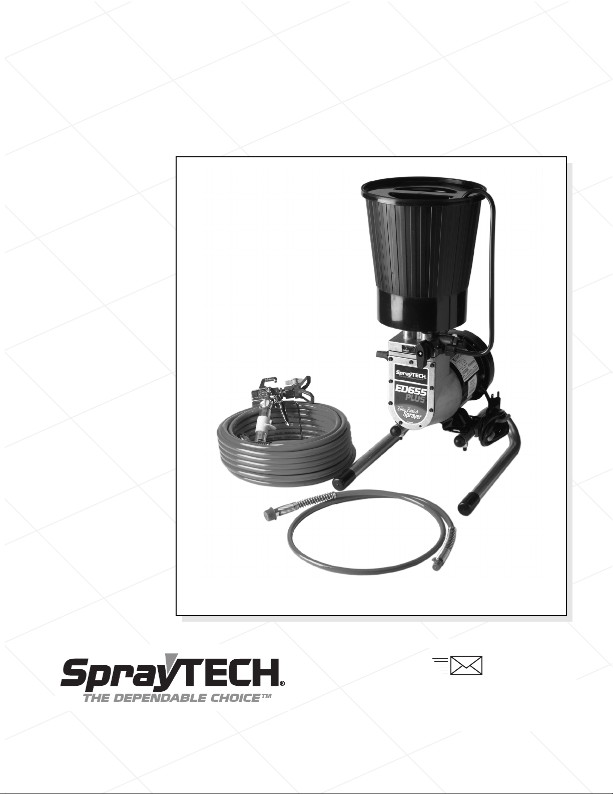
ED655 Plus Airless Pump
SprayTECH
1770 Fernbrook Lane
Minneapolis, MN 55447
Technical Assistance: 1-800-292-4637
Order Entry: 1-800-443-4500
Fax: 1-800-525-9501
www.spraytechinc.com
Owner’s Manual
Printed in the U. S. A.
Model Number 0508090
0505 © 2005 SprayTECH. All rights reserved. Form No. 0508278A
Page 2
Table of Contents
CAUTION
CAUTION
WARNING
WARNING
Safety Precautions. . . . . . . . . . . . . . . . . . . . . . . . . . . . . . . . . 2
Grounding Instructions . . . . . . . . . . . . . . . . . . . . . . . . . . . 3
General Description . . . . . . . . . . . . . . . . . . . . . . . . . . . . . . . . 4
Specifications . . . . . . . . . . . . . . . . . . . . . . . . . . . . . . . . . . 4
Preparing to Paint . . . . . . . . . . . . . . . . . . . . . . . . . . . . . . . . . 4
Attaching the Tip to the Gun. . . . . . . . . . . . . . . . . . . . . . . 4
hecking the Outlet Valve (optional) . . . . . . . . . . . . . . . . 4
C
ttaching the Paint Hose . . . . . . . . . . . . . . . . . . . . . . . . . 5
A
ressure Relief Procedure . . . . . . . . . . . . . . . . . . . . . . . . . . 5
P
Priming . . . . . . . . . . . . . . . . . . . . . . . . . . . . . . . . . . . . . . . . . . 5
Preparing to Prime . . . . . . . . . . . . . . . . . . . . . . . . . . . . . . 5
Mounting the Paint Hopper. . . . . . . . . . . . . . . . . . . . . . . . 6
Attaching the Return Tube . . . . . . . . . . . . . . . . . . . . . . . . 6
Priming the Pump . . . . . . . . . . . . . . . . . . . . . . . . . . . . . . . 6
Spraying . . . . . . . . . . . . . . . . . . . . . . . . . . . . . . . . . . . . . . . . . 7
Spraying Technique . . . . . . . . . . . . . . . . . . . . . . . . . . . . . 7
Practice . . . . . . . . . . . . . . . . . . . . . . . . . . . . . . . . . . . . . . . 7
Cleanup . . . . . . . . . . . . . . . . . . . . . . . . . . . . . . . . . . . . . . . . . . 8
Overnight Storage. . . . . . . . . . . . . . . . . . . . . . . . . . . . . . . 8
Long-Term Storage . . . . . . . . . . . . . . . . . . . . . . . . . . . . . . 8
Maintenance . . . . . . . . . . . . . . . . . . . . . . . . . . . . . . . . . . . . . 10
Removing and Cleaning the Inlet Valves . . . . . . . . . . . . 10
Removing and Cleaning the Outlet Valve. . . . . . . . . . . . 10
Cleaning the Hopper Screen . . . . . . . . . . . . . . . . . . . . . 10
Troubleshooting . . . . . . . . . . . . . . . . . . . . . . . . . . . . . . . . . . 11
Parts Listings . . . . . . . . . . . . . . . . . . . . . . . . . . . . . . . . . . . . 16
Main Assembly . . . . . . . . . . . . . . . . . . . . . . . . . . . . . . . . 16
Diaphragm Pump . . . . . . . . . . . . . . . . . . . . . . . . . . . . . . 17
Pump Head Assembly . . . . . . . . . . . . . . . . . . . . . . . . . . 18
Hopper Assembly . . . . . . . . . . . . . . . . . . . . . . . . . . . . . . 18
Limited Warranty . . . . . . . . . . . . . . . . . . . . . . . . . . . . . . . . . 20
Safety Precautions
This manual contains information which must be read and
understood before using the equipment. When you come to an
area which has one of the following symbols, pay particular
attention and make certain to heed the safeguard.
This symbol indicates a potential hazard which may cause
serious injury or loss of life. Important safety information
will follow.
This symbol indicates a potential hazard to you or to the
equipment. Important information that tells how to prevent
damage to the equipment or how to avoid causes of minor
injuries will follow.
NOTE: Notes give important information which
should be given special attention.
This unit is provided with a thermally protected automatic
reset. If an overload occurs the thermally protected
automatic reset disconnects the motor from the power
supply.
• The motor will restart without warning when the protector
automatically resets.
• Always disconnect the motor from the power supply
before working on the equipment.
• When the thermally protected automatic reset disconnects
the motor from the power supply
turning the priming valve to PRIME.
• Turn the ON/OFF switch to OFF.
, relieve pressure by
NOTE: The cause of the overload should be corrected
A. SAVE THESE INSTRUCTIONS – To reduce the risks of
. WARNING – To reduce the risk of fire or explosion:
B
2 © SprayTECH. All rights reserved.
before restarting. See TROUBLESHOOTING.
IMPORTANT SAFETY INSTRUCTIONS
fire or explosion, electrical shock, and the injury to
persons, read and understand all instructions
included in this manual. Be familiar with the controls
and the proper usage of the equipment.
1. Do not spray flammable or combustible materials near
an open flame, pilot lights or sources of ignition such as
hot objects, cigarettes, motors, electrical equipment and
electrical appliances. Avoid creating sparks from
connecting and disconnecting power cords.
2. For units intended for use with only water-based
materials — Do not spray or clean with flammable
liquids. For use with water-based liquids only.
3. For units intended for use with only water-based or
mineral spirit-type materials with a minimum flash point
of 21ºC (69.8ºF) — Do not spray or clean with liquids
having a flash point of less than 21ºC (69.8ºF). Flash
point is the temperature at which a fluid can produce
enough vapor to ignite.
4. Paint or solvent flowing through the equipment is able
to result in static electricity. Static electricity creates a
risk of fire or explosion in the presence of paint or
solvent fumes. All parts of the spray system, including
the pump, hose assembly, spray gun and objects in and
around the spray area shall be properly grounded to
protect against static discharge and sparks. Use only
conductive or grounded high-pressure airless paint
sprayer hoses specified by the manufacturer.
5. Verify that all containers and collection systems are
grounded to prevent static discharge.
6. Connect to a grounded outlet and use grounded
extension cords. Do not use a 3 to 2 adapter.
7. Do not use a paint or solvent containing halogenated
hydrocarbons. Such as chlorine, bleach mildewcide,
methylene chloride and trichloroethane. They are not
compatible with aluminum. Contact the coating
supplier about compatibility of material with aluminum.
8. Keep spray area well ventilated. Keep a good supply of
fresh air moving through the area to keep the air within
the spray area free from accumulation of flammable
vapors. Keep pump assembly in well ventilated area.
Do not spray pump assembly
9. Do not smoke in the spray area.
10. Do not operate light switches, engines, or similar spark
producing products in the spray area.
11. Keep area clean and free of paint or solvent
containers, rags, and other flammable materials.
12. Know the contents of the paint and solvents being
sprayed. Read all Material Safety Data Sheets (MSDS)
and container labels provided with the paints and
solvents. Follow the paint and solvent manufacture’s
safety instructions.
13. Place pump at least 25 feet (7.62 meters) from the
spray object in a well ventilated area (add more hose if
necessary). Flammable vapors are often heavier than
air. Floor area must be extremely well ventilated. The
pump contains arcing parts that emit sparks and can
ignite vapors.
14. Plastic can cause static sparks. Never hang plastic to
enclose spray area. Do not use plastic drop cloths
when spraying flammable material.
15. Fire extinguisher equipment shall be present and
working.
.
Page 3
C. WARNING – To reduce the risk of skin injection:
WARNING
WARNING
CAUTION
Grounded Outlet
Grounding Pin
Cover for grounded outlet box
AZARD:
H
Injection injury – A high pressure fluid stream produced
by this equipment can pierce the skin and underlying
tissues, leading to a serious injury and possible
amputation. See a physician immediately. DO NOT
TREAT AN INJECTION AS A SIMPLE CUT.
. Do not aim the gun at, or spray any person or animal.
1
2. Keep hands and other body parts away from the
discharge. For example, do not try to stop leaks with
any part of the body.
3. Always use the nozzle tip guard. Do not spray without
the nozzle tip guard in place.
4. Only use a nozzle tip specified by the manufacturer.
5. Use caution when cleaning and changing nozzle tips.
In the case where the nozzle tip clogs while spraying,
ALWAYS lock gun trigger, shut pump off, and release all
pressure before servicing, cleaning tip or guard, or
changing tip. Pressure will not be released by turning
off the motor. The PRIME/SPRAY valve handle must
be turned to PRIME to relieve the pressure. Refer to
PRESSURE RELIEF PROCEDURE described in the
pump manual.
6. Do not leave the unit energized or under pressure while
unattended. When the unit is not in use, turn off the unit
and relieve the pressure in accordance with the
manufacturer’s instructions.
7. High-pressure spray is able to inject toxins into the
body and cause serious bodily injury. In the event that
injection occurs, seek medical attention immediately.
8. Check hoses and parts for signs of damage, a leak can
inject material into the skin. Inspect hose before each
use. Replace any damaged hoses or parts.
9. This system is capable of producing 2800 PSI / 19.3
MPa. Only use replacement parts or accessories that
are specified by the manufacturer and that are rated a
minimum of 3100 PSI. This includes spray tips, nozzle
guards, guns, extensions, fittings, and hose.
10. Always engage the trigger lock when not spraying.
Verify the trigger lock is functioning properly.
11. Verify that all connections are secure before operating
the unit.
Know how to stop the unit and bleed pressure quickly.
12.
Be thoroughly familiar with the controls. Pressure will
not be released by turning off the motor
PRIME/SPRAY
to relieve the pressure. Refer to PRESSURE RELIEF
PROCEDURE described in the pump manual.
13. Always remove the spray tip before flushing or cleaning
the system.
valve handle must be turned to PRIME
The
.
6. Do not kink or over-bend the hose. Airless hose can
develop leaks from wear, kinking and abuse. A leak
can inject material into the skin.
. Do not expose the hose to temperatures or pressures in
7
xcess of those specified by manufacturer.
e
8. Do not use the hose as a strength member to pull or lift
the equipment.
9. Use lowest possible pressure to flush equipment.
10. Follow all appropriate local, state and national codes
governing ventilation, fire prevention and operation.
11. The United States Government Safety Standards have
been adopted under the Occupational Safety and
Health Act (OSHA). These standards, particularly part
1910 of the General Standards and part 1926 of the
Construction Standards should be consulted.
12. Before each use, check all hoses for cuts, leaks,
abrasion or bulging of cover. Check for damage or
movement of couplings. Immediately replace hose if
any of those conditions exist. Never repair a paint hose.
Replace with a conductive high-pressure hose.
13. Do not spray outdoors on windy days.
14. Always unplug cord from outlet before working on
equipment.
Grounding Instructions
This product must be grounded. In the event of an electrical
short circuit, grounding reduces the risk of electric shock by
providing an escape wire for the electric current. This product
is equipped with a cord having a grounding wire with an
appropriate grounding plug. The plug must be plugged into an
outlet that is properly installed and grounded in accordance
with all local codes and ordinances.
DANGER — Improper installation of the grounding plug can
result in a risk of electric shock. If repair or replacement of the
cord or plug is necessary, do not connect the green grounding
wire to either flat blade terminal. The wire with insulation
having a green outer surface with or without yellow stripes is
the grounding wire and must be connected to the grounding
pin.
Check with a qualified electrician or serviceman if the
grounding instructions are not completely understood, or if you
are in doubt as to whether the product is properly grounded.
Do not modify the plug provided. If the plug will not fit the
outlet, have the proper outlet installed by a qualified
electrician.
D. WARNING – To reduce the risk of injury:
1. Always wear appropriate gloves, eye protection,
clothing and a respirator or mask when painting.
Hazardous vapors – Paints, solvents, insecticides, and
other materials can be harmful if inhaled or come in
contact with body
fainting or poisoning.
Do not operate or spray near children. Keep children
2.
away from equipment at all times.
3. Do not overreach or stand on an unstable support.
Keep effective footing and balance at all times.
Stay alert and watch what you are doing.
4.
Do not operate the unit when fatigued or under the
5.
influence of drugs or alcohol.
© SprayTECH. All rights reserved.. 3
apors can cause severe nausea,
. V
Use only a 3-wire extension cord that has a 3-blade
grounding plug and a 3-slot receptacle that will accept the
plug on the product. Make sure your extension cord is in
good condition. When using an extension cord, be sure
to use one heavy enough to carry the current your
product will draw. An undersized cord will cause a drop
in line voltage resulting in loss of power and overheating.
A 12 gauge cord is recommended. If an extension cord is
to be used outdoors, it must be marked with the suffix WA after the cord type designation. For example, a
designation of SJTW-A would indicate that the cord would
be appropriate for outdoor use.
Page 4
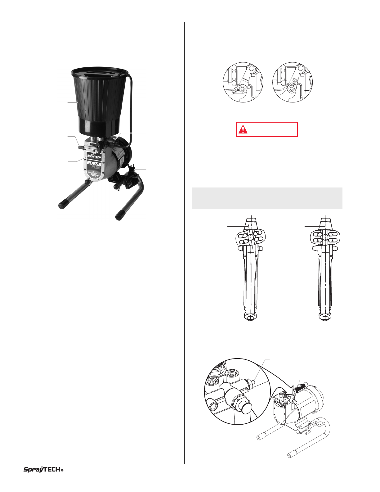
General Description
Pressure Control
Knob
PRIME/SPRAY
Knob
Paint Hopper Return Tube
Outlet Valve
Power Cord
Pusher Valve Button
(optional)
Begin
tightening
the tip guard
at this angle
to achieve
the desired
spray angle
when tight.
WARNING
Trigger locked
(gun will not spray)
Trigger unlocked
(gun will spray)
This high performance airless sprayer is a precision power tool
used for spraying many types of materials. Read and follow
this instruction manual carefully for proper operating
instructions, maintenance and safety information.
Preparing to Paint
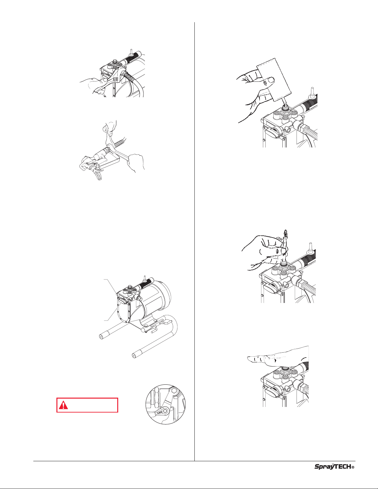
Attaching the Tip to the Gun
1. Lock the trigger by rotating the trigger lock forward until it
stops.
POSSIBLE INJECTION HAZARD. Do not spray without the
tip guard in place. Never trigger the gun unless the tip is
in either the spray or the unclog position. Always engage
the gun trigger lock before removing, replacing or
cleaning tip.
2. Thread the tip guard onto the gun. Tighten the nut first by
hand, then tighten more firmly with a wrench.
NOTE: When attaching the tip guard to the gun, align
the tip guard as shown in the figure below,
then tighten with a wrench.
Specifications
Weight ..............................27 lbs
Capacity ...........................Up to .35 gallon (1.25 liters) per
Power source ...................Electric motor, totally enclosed, fan
Power requirement...........15 amp minimum circuit on 115
Generator .........................15 amp A/C.
Spraying pressure ............Up to 2750 PSI
Capabilities
.......................Sprays a variety of oil-based and
minute
cooled
VAC, 60 Hz current.
latex paints, primers, and stains
Checking the Outlet Valve (optional)
Firmly press the optional pusher valve button on the side
1.
of the pump housing to make sure the outlet ball valve
moves freely.
4 © SprayTECH. All rights reserved.
Page 5
Attaching the Paint Hose
WARNING
Trigger locked
(gun will not spray)
Pressure Control Knob
PRIME/SPRAY Knob
. Attach the high pressure hose to the paint sprayer. Use a
1
rench to tighten the paint hose securely.
w
2. Attach the spray gun to the other end of the high pressure
hose. Tighten the hose securely to the gun using two
wrenches.
3. Plug the sprayer into a properly grounded outlet or heavy
duty grounded extension cord. Do not use more than 100
feet of cord. If you must spray a long distance from a
power source, use more paint hose, not more extension
cords. Use a minimum size of 16 gauge extension cord
for up to 50 feet in length, or 12 to 14 gauge for extension
cords between 50 and 100 feet in length.
Priming
Preparing to Prime
1. Fill the inlet valve with water or with a light household oil.
2. Make sure the PRIME/SPRAY knob is set to PRIME and
that the pressure control knob is turned counterclockwise
to the lowest pressure setting.
3. Turn the motor switch to ON.
4. Increase the pressure by turning the pressure control
knob clockwise 1/2 turn.
5. Force the inlet valve to open and close by pushing on it
with a screwdriver or the eraser end of a pencil. It should
move up and down about 1/16 of an inch. Continue until
water or oil is sucked into the sprayer. This will wet the
moving parts and break loose any old paint residue.
Pressure Relief Procedure
Follow this procedure after the unit is assembled and before
any operation which involves the spray gun such as cleaning
and maintenance or changing tips or accessories.
1. Turn the pressure control knob counterclockwise to its
lowest setting.
2. Turn the PRIME/SPRAY knob to PRIME.
3. Trigger the gun to remove any pressure which may still be
in the hose.
4. Lock the trigger by rotating the trigger
lock forward until it stops.
Injection hazard. Do not spray without
the tip guard in place. NEVER trigger
the gun unless the tip is completely
turned to either the spray or the unclog
position. ALWAYS engage the gun trigger lock before
removing, replacing or cleaning tip.
6. Put the palm of your hand over the inlet. Turn the
pressure control knob clockwise to its maximum setting.
ou should feel suction coming from the inlet valve. If you
Y
do not, see the section on cleaning and servicing the outlet
valve.
7. Turn the pressure control knob counterclockwise to the
minimum pressure setting.
urn the motor switch to OFF
T
8.
.
© SprayTECH. All rights reserved. 5
Page 6
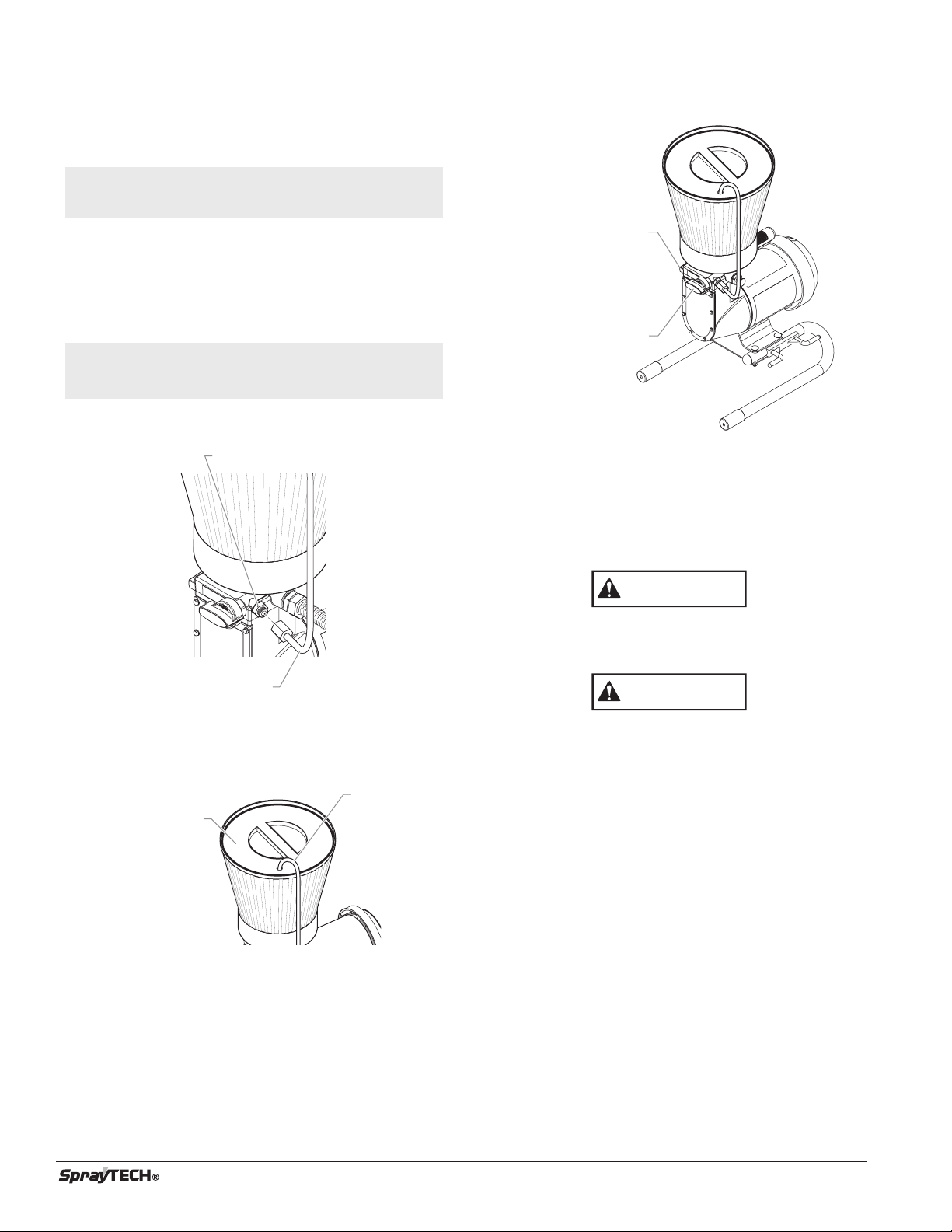
Mounting the Paint Hopper
Return Tube
Paint Hopper Cover
Return Tube Fitting
Return Tube
CAUTION
CAUTION
Pressure Control Knob
PRIME/SPRAY Knob
1. Align the bottom of the paint hopper with the threaded
inlet valve on the paint pump block.
. Turn the paint hopper clockwise to thread it onto the inlet
2
valve. Continue to turn the paint hopper until it is secure
on the inlet valve.
NOTE: Make sure the threads are straight and the
3. Place the filter screen into the bottom of the paint hopper
hopper turns freely on the inlet valve. Do not
cross-thread.
and snap it in position.
Attaching the Return Tube
1. Make sure that the motor switch is turned to OFF.
2. Screw the return tube fitting found in the literature set into
the return tube port on the side of the pump.
NOTE: Do not over-tighten. Hand-tighten only. Some
threads will be visible even when fully
tightened.
3. Place the straight end of the return tube into the return
tube fitting.
Priming the Pump
. Turn the pressure control knob counterclockwise to its
1
owest pressure setting.
l
2. Remove the paint hopper cover and fill the paint hopper
with material.
3. Turn the PRIME/SPRAY knob to PRIME.
4. Turn the motor switch to ON.
5. Turn the pressure control knob clockwise to between half
and full pressure. Let the unit prime 1 to 2 minutes after
material begins to flow through the return tube.
4. Thread the nut on the return tube onto the return tube
fitting and tighten until the return tube is secure.
5. Place the hook end of the return tube into the hole in the
paint hopper cover
Always reduce the pressure to zero before changing the
position of the PRIME/SPRAY knob. Failure to do so may
cause damage to the paint pump diaphragm.
If the pressure control knob is reduced to zero and the
PRIME/SPRAY knob is still on SPRAY while the sprayer is
.
operating, there will be high pressure in the hose and
spray gun until the PRIME/SPRA
or until the spray gun is triggered to relieve the pressure.
knob is turned to PRIME
Y
6 © SprayTECH. All rights reserved.
Page 7

Spraying
Approximately
10 to 12 inches
Right way
Wrong way
Keep stroke smooth and at an even speed.
Even coat throughout
Approximately
10 to 12 inches
Heavy Coat
Do not flex wrist while spraying.
Light Coat Light Coat
Good spray pattern
Paint tailing pattern
Pressure Control Knob
PRIME/SPRAY Knob
P
roper way to trigger the spray gun
Aproximately
1
0 to 12 inches
Keep stroke
e
ven
Start stroke End strokePull trigger Release triggerKeep steady
Spraying Technique
The key to a good paint job is an even coating over the entire
surface. This is done by using even strokes. Keep your arm
moving at a constant speed and keep the spray gun at a
constant distance from the surface. The best spraying
distance is 10 to 12 inches between the spray tip and the
surface.
Keep the spray gun at right angles to the surface. This means
moving your entire arm back and forth rather than just flexing
your wrist.
Overlap each stroke by about 30%. This will ensure an even coating.
hen you stop painting, lock the gun trigger lock, turn the
W
pressure control knob counterclockwise to its lowest setting
and set the PRIME/SPRAY knob to PRIME. Turn the motor
switch to OFF and unplug the sprayer.
If you expect to be gone more than 1 hour, follow the short
term clean up procedure described in the CLEANUP section of
this manual.
Practice
1. Be sure that the paint hose is free of kinks and clear of
objects with sharp cutting edges.
2. Turn the pressure control knob counterclockwise to its to
its lowest setting.
Keep the spray gun perpendicular to the surface, otherwise
one end of the pattern will be thicker than the other.
The spray gun should be triggered by turning it on and off with
each stroke.
end of the stroke. Do not trigger the gun during the middle of a
This will save paint and avoid paint buildup at the
stroke. This will result in an uneven spray and splotchy
coverage.
© SprayTECH. All rights reserved. 7
3. Turn the PRIME/SPRAY knob to SPRAY.
4. Turn the pressure control knob clockwise to its highest
setting. The paint hose should stiffen as paint begins to
flow through it.
5. Unlock the gun trigger
lock by turning the
switch so that it is
parallel to the handle.
6. Trigger the spray gun to
bleed air out of the
hose.
7. When paint reaches the
spray tip, spray a test
area to check the spray
pattern.
Use the lowest pressure setting necessary to get a good
8.
spray pattern. If the pressure is set too high, the spray
pattern will be too light. If the pressure is set too low,
tailing will appear or the paint will spatter out in gobs
rather than in a fine spray.
Page 8

Cleanup
Trigger locked
(gun will not spray)
Trigger locked
(gun will not spray)
CAUTION
WARNING
Overnight Storage
Long-Term Storage
Shutdown
. Turn the pressure control knob counterclockwise to the
1
inimum setting.
m
. Turn the PRIME/SPRAY knob to PRIME to release system
2
ressure.
p
3. Trigger the gun to remove any pressure that may still be in
he hose.
t
4. Lock the trigger by rotating the trigger
lock forward until it stops.
5. Turn the motor switch to OFF and
unplug the sprayer.
6. For latex materials only, pour 1/2 cup
water slowly on the top of the paint to
prevent the paint from drying. For
other materials, seal the paint hopper
with the hopper cover keeping the
return tube in the paint.
7. Wrap the spray gun assembly in a damp cloth and place it
in a plastic bag. Seal the bag shut.
8. Place the sprayer in a safe place out of the sun for short-
term storage.
Startup
1. Remove the gun from the plastic bag.
2. Stir the water into the paint for latex materials. Remove
the hopper cover from the paint hopper and stir the paint
for all other materials.
Do not allow paint to build up on the motor or the motor
will overheat. Do not allow flammable solvents to come in
ontact with the motor or they could ignite.
c
NOTE: You will need a bucket, cleaning solution, a
NOTE: If spraying with latex paint, use warm soapy
Do not use mineral spirits or paint thinner on latex paint,
or the mixture will turn into a jelly-like substance which is
difficult to remove.
oothbrush, a wrench and cleaning rags.
t
ater for cleaning. If using oil or alkyd-based
w
aints, use mineral spirits or paint thinner.
p
Clearing the Paint Hopper
1. Lock the gun trigger by rotating the
trigger lock forward until it stops.
2. Turn the pressure control knob
counterclockwise to the minimum
setting.
3. Turn the PRIME/SPRAY knob to
PRIME.
4. Turn the motor switch to OFF.
5. Direct the return tube into the original
paint bucket.
6. Turn the motor switch to ON.
7. Turn the pressure control knob to 1/2 maximum pressure.
This will draw the remaining paint in the paint hopper through
the pump, up the return tube, and into the paint bucket.
8. Turn the pressure control knob counterclockwise to the
minimum pressure setting.
9. Trigger the gun to relieve pressure and lock the gun.
10. Remove the spray tip and guard and place them into a
container of water or appropriate solvent for the type of
material with which you are painting.
Fill the paint hopper with water or an appropriate solvent
1.
1
for the type of material with which you are painting.
12. Direct the return tube into a waste bucket.
13. Increase the pressure to 1/2 the maximum pressure. Let
the water or solvent circulate for 2-3 minutes to flush paint
out of the pump, the paint hopper
, and the return tube.
Clearing the Paint Hose
1. To save paint left in the hose, release the gun trigger lock
and carefully trigger the gun with the spray tip removed
against the inside of the paint container
.
Check to be sure that the PRIME/SPRA
3.
PRIME and that the pressure is completely reduced.
Plug sprayer in and turn the motor switch to ON.
4.
5. After the sprayer is primed, turn the PRIME/SPRAY knob
to SPRAY and gradually turn the pressure control knob
clockwise to increase the pressure.
6. Test the sprayer on a practice piece and begin spraying.
Y knob is set to
2. Turn the pressure control knob counterclockwise to the
minimum pressure setting.
3. Turn the PRIME/SPRAY knob to SPRAY.
8 © SprayTECH. All rights reserved.
Page 9

4. Turn the pressure control knob slowly until paint starts to
flow into the bucket. As soon as the water or solvent
starts to come into the bucket, release the trigger.
5. Change to clean water or solvent, point the gun to the
side of the waste bucket, and continue circulating for
another 5 minutes to thoroughly clean the hose, pump and
spray gun.
6. Turn the pressure control knob counterclockwise to its
lowest setting.
7. Turn the PRIME/SPRAY knob to PRIME.
8. Trigger the gun to remove any pressure which may still be
in the hose.
9. Lock the gun trigger by rotating the trigger lock forward
until it stops.
0. Turn the motor switch to OFF.
1
Clearing the Gun
1. Remove the spray gun from the paint hose using two
adjustable wrenches.
2. Remove the filter housing from the gun. Place the gun
and the filter assembly into a container of water or solvent
to soak.
3. Cover the paint container and set it aside.
4. Clean the spray tip and gun filter with a soft brush.
5. Reassemble the gun and filter. Assemble the spray tip in
the cleaning position with the arrow pointing to the back of
the gun.
13. Trigger the gun to remove any pressure which may still be
in the hose.
14. Lock the gun trigger by rotating the trigger lock forward
until it stops.
5. Turn the motor switch to OFF.
1
Final Cleanup
1. Remove the tip assembly.
2. Turn the motor to ON.
3. Turn the PRIME/SPRAY knob to SPRAY.
4. Turn the pressure control knob clockwise to 1/2 power.
. Trigger the gun into the cleaning bucket until the hopper is
5
empty.
. Refill the hopper and continue flushing the system until
6
he solution coming out of the gun appears clean.
t
7. Lock the gun and turn the pressure control knob
counterclockwise to its lowest setting.
8. Turn the PRIME/SPRAY knob to PRIME.
9. Remove the hopper from the inlet valve.
10. Clean the threads of the inlet valve with a damp cloth.
11. Fill the inlet valve with a light household oil.
6. Attach the paint hose to the gun and tighten using two
wrenches.
7. Turn the motor switch to ON.
8. Unlock gun trigger by turning the gun trigger lock so that it
is parallel to the gun handle.
9. Turn the PRIME/SPRAY knob to SPRAY and point the gun
to the side of the waste bucket.
10 Trigger the gun and gradually turn the pressure control
knob clockwise to 1/2 pressure. Continue to trigger the
gun for approximately 30 seconds.
11. Turn the pressure control knob counterclockwise to its
lowest setting.
12. Turn the PRIME/SPRAY knob to PRIME.
12. Turn the PRIME/SPRAY knob to SPRAY to distribute the
oil.
NOTE: Proper cleaning and oiling of the pump after
13. Turn the pressure control knob counterclockwise to its
14. Turn the PRIME/SPRAY knob to PRIME.
15. T
16.
17.
18. Remove the hopper filter and clean in clean water or the
19. Return the hopper filter to its position in the hopper and
20. Wipe the entire unit, hose and gun with a damp cloth to
use are the most important steps you can take
to insure proper operation after storage.
lowest setting.
rigger the gun to remove any pressure that may still be
in the hose.
Lock the gun trigger by rotating the trigger lock forward
until it stops..
urn the motor switch to OFF
T
appropriate solvent. Use a soft brush.
replace the hopper on the inlet valve.
remove accumulated paint.
.
© SprayTECH. All rights reserved. 9
Page 10

Maintenance
Valve Body
O-ring
Seal
Seat
Ball
Spring
Ball Stop
Follow these procedures when encountering problems
indicated in the troubleshooting section.
Removing and Cleaning the Inlet Valves
1. Be certain that the sprayer is off.
2. Remove the inlet valve assembly using a 27 millimeter
socket or box end wrench.
3. Test movement of the valve by pushing on it from the
open end of the valve housing with a screwdriver or the
eraser end of a pencil. It should move about 1/16 of an
inch. If it does not move, it should be cleaned or
replaced.
OTE: This spring is manufactured to a very specific
N
3. Remove the seat and ball assembly.
4. Clean all parts thoroughly. If the ball or seat show any
5. Cover all parts with a thin coat of light oil before
NOTE: You will need to align the ridge on the seat with
6. Drop in the valve ball.
7. Insert the ball stop and spring and replace the valve body.
8. Tighten the valve body securely with an adjustable
tension. Do not put in an unauthorized
substitute. See the paint pump assembly parts
diagram for the proper replacement part
number.
sign of wear or damage, replace them with new parts.
This carbide ball must seal tightly against its seat for the
valve to function properly.
reassembling.
the groove in the pump housing when
reassembling.
Be sure that the o-ring is positioned properly and that the
tongue on the cap fits inside the spring.
wrench. Do not over-tighten.
NOTE: The inlet valve must be oiled after every job.
4. Thoroughly clean the valve assembly with water or the
5. If you have properly cleaned the valve and water drips out
6. Install a new or cleaned valve in the pump block and then
This will reduce or eliminate priming problems
the next time the sprayer is used.
appropriate solvent. Use a small brush.
of the bottom, the valve is worn and needs to be replaced.
properly seated valve filled with water and held vertically
A
will not drip.
fill the valve with light oil or solvent.
Removing and Cleaning the Outlet Valve
It may be necessary to remove and clean the outlet valve or to
replace parts inside the valve worn out through normal use.
1. Remove the outlet valve body with a wrench.
Remove and clean the ball stop and small spring inside
2.
the valve using a wire hook or tweezers. Replace the
spring if it is broken or worn.
Cleaning the Hopper Screen
The screen at the bottom of the paint hopper may need
cleaning periodically. Check it every time you add paint.
Remove the screen by pulling it out of the hopper with a pliers.
Clean the screen with water or solvent and a soft-bristle brush,
if necessary.
10 © SprayTECH. All rights reserved.
Page 11

P
roblem
The sprayer does not start up.
Troubleshooting
C
ause
1. The sprayer is not plugged in.
. The ON/OFF switch is set to OFF.
2
3. Low or no voltage is coming from the
wall plug.
4. The sprayer was turned off while still under
pressure.
5. The extension cord is damaged or has too
low a capacity.
6. The thermal overload on the sprayer is
tripped.
7. There is a problem with the motor.
S
olution
1. Plug the sprayer in.
. Turn the ON/OFF switch to ON.
2
3. Properly test the power supply voltage.
4. Turn the PRIME/SPRAY knob to PRIME.
5. Replace the extension cord.
6. Allow the motor to cool and move the sprayer to a
cooler spot.
7. Take the sprayer to a SprayTECH Authorized Service
Center.
The sprayer starts up but does not
draw in paint when the
PRIME/SPRAY knob is set to
PRIME.
The sprayer draws up paint but
the pressure drops when the gun
is triggered.
The sprayer will not shut off.
The spray gun leaks.
The tip assembly leaks.
1. The unit will not prime properly or has lost prime.
2. The paint hopper is empty
3. The hopper filter is clogged.
4. The inlet valve is stuck.
5. The outlet valve is stuck.
6. The PRIME/SPRAY valve is plugged.
7.
The inlet valve is worn or damage.
. There is a problem with the diaphragm.
8
9. The hydraulic oil level is low or empty.
1. The spray tip is worn.
2. The hopper filter is clogged.
3. The gun or spray tip filter is plugged.
4. The paint is too heavy or coarse.
5. The outlet valve assembly is dirty or worn.
6. The inlet valve assembly is damaged or worn.
1. The inlet or outlet valve ball or ball seat is
worn.
2. Foreign matter or paint has built up between
the ball and the seat.
1. Internal parts of the gun are worn
or dirty.
1. The tip was assembled incorrectly.
2. A seal is worn.
1. Try to prime the unit again.
2. Fill the paint hopper with paint.
3. Clean the hopper filter.
4. Clean the inlet valve.
5. Clean the outlet valve and replace any
worn parts.
6. Take the sprayer to a SprayTECH Authorized Service
Center.
7.
Replace the inlet valve.
. Take the sprayer to a SprayTECH Authorized Service
8
Center.
9. Take the sprayer to a SprayTECH Authorized Service
Center.
1. Replace the spray tip with a new tip.
2. Clean the hopper filter.
3. Clean or replace the proper filter. Always keep
extra filters on hand.
4. Thin or strain the paint.
5. Clean or replace the outlet valve assembly.
6. Replace the inlet valve.
1. Take the sprayer to a SprayTECH Authorized
Service Center.
2. Take the sprayer to a SprayTECH Authorized
Service Center.
1. Take the sprayer to a SprayTECH Authorized
Service Center.
1. Check the tip assembly and assemble properly.
2. Replace the seal.
The spray gun will not spray.
The paint pattern is tailing.
The thermal overload tripped and
shut off the sprayer.
NOTE:
When the PRIME/SPRA
1. The spray tip, the gun filter or the tip filter is
plugged.
2. The spray tip is in the CLEAN position.
1. The pressure is set too low.
The gun, the tip, or the hopper filter
2.
is plugged.
3. The tip is worn.
4. The paint is too thick.
1. The motor overheated.
2. The extension cord is too long or is too
small a gauge.
3. Paint has built up on the motor.
4. The motor was started while the sprayer
was under pressure.
5. The sprayer was sitting in the hot sun.
valve is on SPRAY and there is flow through the return tube, remove the
Y
PRIME/SPRAY valve and clean or replace it.
NOTE:
The electric motor should always be kept clean and dry
motor will cause the motor to overheat.
© SprayTECH. All rights reserved. 11
1. Clean the spray tip, gun filter or tip filter.
2. Put the tip in the SPRAY position.
1. Increase the pressure.
2. Clean the filters.
3. Replace the spray tip.
4. Thin the paint.
Allow to cool for 30 minutes.
1.
2. Allow to cool for 30 minutes and replace the
extension cord with a shorter extension or a thicker
gauge cord.
3. Clean the paint from the motor.
4. Restart the sprayer in the PRIME mode.
5. Move the sprayer out of the sun.
. Paint acts as an insulator
. Too much paint on the
Page 12

Consignes de sécurité
AVERTISSEMENT
ATTENTION
AVERTISSEMENT
CET ENSEMBLE EST DOTÉ D'UN DISPOSITIF DE REMISE
EN MARCHE AUTOMATIQUE AVEC PROTECTION
THERMIQUE. EN CAS DE SURCHARGE, CE DISPOSITIF
DÉBRANCHE LE MOTEUR DU BLOC D'ALIMENTATION.
• Le moteur se remet en marche sans avertissement
lorsque le protecteur est réarmé automatiquement.
Il faut toujours débrancher le moteur du bloc
•
'alimentation avant de travailler sur le matériel.
d
• Lorsque le dispositif de remise en marche automatique
débranche le moteur du bloc d'alimentation, réduire la pression
en tournant la soupape d'amorçage à AMORCER.
• Mettre l'interrupteur MARCHE/ARRÊT à ARRÊT.
NOTA : Il faut remédier à la cause de la surcharge
DANGER: Blessures résultant d'une injection cutanée - Le
NE PAS TRAITER CE TYPE DE BLESSURE COMME S'IL
S'AGISSAIT D'UNE SIMPLE COUPURE ! Une amputation
peut en résulter. Consulter un médecin immédiatement.
Le plus haut niveau de fonctionnement du pistolet est une
pression du fluide de 2800 PSI.
PRÉVENTION:
• NE JAMAIS diriger le pulvérisateur vers toute partie du corps.
• NE JAMAIS placer toute partie du corps devant le jet.
• NE JAMAIS placer les mains devant le pulvérisateur. Les
• TOUJOURS bloquer la détente du pistolet, fermer la pompe à
• Toujours débrancher le pistolet avant d'effectuer toute
•
• TOUJOURS enlever la tête de pulvérisation avant
•
• NE JAMAIS utiliser un pistolet qui ne soit pas muni d'un
•
avant de relancer l'appareil. À ce sujet, voir la
rubrique DÉPANNAGE.
jet de peinture haute pression produit par cet
appareil peut transpercer la peau et les tissus
sous-jacents, causant des blessures graves
pouvant aller jusqu'à l'amputation.
ÉVITER d'entrer en contact avec un jet de fluide sortant
d'une fuite dans le tuyau à fluide.
gants ne sont pas une protection suffisante contre les
risques d'injection cutanée.
fluide et décharger toute la pression avant de faire de l'entretien,
de nettoyer le protecteur de la tête, de changer de tête ou de
laisser l'appareil sans surveillance. Le bouton
AMORCER/PULVÉRISER doit être tourné à AMORCER, afin
d'éliminer la pression. Consulter la PROCÉDURE DE
ATION DE LAPRESSION décrite dans le présent manuel.
LIMIT
opération d'entretien ou de nettoyage du protecteur de
tête ou de remplacement des embouts, ou lorsque le
pistolet n'est pas utilisé.
OUJOURS garder le protecteur de tête en place durant
T
l'opération de pulvérisation. Ce dispositif fournit une
certaine protection contre toute blessure résultant d'une
injection cutanée; on l'utilise principalement à titre
d'avertissement.
d'effectuer un lavage ou un nettoyage du système.
Des fuites peuvent être provoquées dans le tuyau à
peinture par l'usure, par des faux plis ou par la mauvaise
utilisation. Une fuite peut injecter des substances dans la
peau, et il est donc indispensable d'examiner le tuyau à
peinture avant chaque utilisation.
cran de sûreté ou de pontet en place et en bon état de
fonctionnement.
ous les accessoires doivent avoir une valeur nominale
T
d'au moins 2800 PSI. Cette exigence s'applique aux têtes
de pulvérisation, aux pistolets, aux rallonges et aux tuyaux.
REMARQUE DESTINÉE AU MÉDECIN:
Une injection cutanée est une blessure du type
traumatique. Il est essentiel de traiter ce genre de
blessure à l'aide d'une intervention chirurgicale et ce,
dans les plus brefs délais. NE PAS retarder le traitement
dans le but d'effectuer des recherches sur le degré de
toxicité du produit. La toxicité d'un produit ne doit être
considérée que pour certaines substances ayant été
directement injectées dans les vaisseaux sanguins. Il
pourrait s'avérer nécessaire de consulter un spécialiste
en chirurgie plastique, ou encore, un spécialiste en
chirurgie reconstructive de la main.
DANGER: EXPLOSION OU INCENDIE - Les émanations
RÉVENTION:
P
• Un approvisionnement d'air frais et une évacuation des
• Éviter toute source d'ignition, telle que des étincelles
• Des appareils d'extinction d'incendie doivent être en place
• Garder la pompe à l'écart de la zone de pulvérisation, afin
• L'écoulement à haute vitesse d'un liquide à travers le
• Pour le travail sans air, utiliser uniquement les tuyaux à
• Respecter les mesures de sécurité et les avertissements
•
DANGER: EXPLOSION CAUSÉE P
PRÉVENTION:
•
•
provenant des solvants et des peintures peuvent
exploser ou s'enflammer, entraînant des
dommages matériels ou des blessures graves.
gaz doivent être assurés, afin que l'air entourant la zone
de pulvérisation soit libre de toute accumulation de
vapeurs inflammables.
d'électricité statique, des flammes nues, des veilleuses,
des objets chauds, des cigarettes, ou des étincelles
produites lors du branchement ou du débranchement des
cordons d'alimentation ou du déclenchement des
interrupteurs d'éclairage.
et en bon état de fonctionnement.
d'éviter les vapeurs de solvants et de peintures.
matériel peut générer l'électricité statique. Il faut donc
assurer une bonne mise à la terre du matériel dont on se
sert ainsi que des objets dans la zone de pulvérisation et
aux alentours, pour éviter la décharge de l'électricité
statique et les étincelles.
fluide à haute pression qui soient mis à la terre ou qui
soient bons conducteurs de l'électricité. S'assurer que le
pistolet est mis à la terre correctement à travers les
raccords des tuyaux.
du fabricant des solutions et des produits.
Lors du lavage du matériel, utiliser la plus basse pression
possible.
TIBILITÉ
DES MATÉRIAUX - Peut causer des dommages
AR L'INCOMP
matériels ou des blessures graves.
Ne pas utiliser de l'eau de Javel.
Ne pas utiliser de solutions halocarbonées, tels que le
chlorure de méthylène et le 1-1-1 trichloro-éthane. Ces
produits ne sont pas compatibles avec l'aluminium et
peuvent provoquer une explosion. En cas de doute,
communiquer avec le fournisseur du produit en question.
A
Français
12 © SprayTECH. Tous droits réservés.
Page 13

DANGER: VAPEURS DANGEREUSES - Les peintures, les
ATTENTION
ATTENTION
Prise de terre
Goupille de mise à la terre
Couvercle du boîtier de prise de terre
PRÉVENTION:
• Utiliser un respirateur ou un masque dans toute situation où il
• Utiliser des lunettes de protection pour empêcher les
ANGER :GÉNÉRALITÉS - Peut causer des dommages
D
PRÉVENTION:
• Lire toutes les directives et toutes les mesures de sécurité
• Se conformer aux règlements locaux, provinciaux et
• Les normes de sécurité du gouvernement des États-Unis
• Cette pompe, qui fonctionne à haute pression sans air, est
• Avant chaque utilisation, vérifier tous les tuyaux pour
• Tous les tuyaux, pivots, pistolets et accessoires utilisés avec ce
• Ne pas pulvériser par des temps de grand vent.
solutions, les insecticides et autres produits
peuvent être dangereux en cas d'inhalation,
provoquant des nausées graves, des
évanouissements ou un empoisonnement.
y a risque d'inhalation de vapeurs. Lire toute la
documentation accompagnant le produit de pulvérisation et le
masque, afin de s'assurer qu'une protection adéquate est
offerte contre l'inhalation de vapeurs dangereuses.
vapeurs dangereuses de pénétrer dans les yeux.
atériels ou des blessures graves
m
portant sur l'équipement et sur le produit de pulvérisation
avant l'emploi de tout équipement.
nationaux appropriés régissant la ventilation, laprévention
des incendies et l'exécution des opérations.
ont été adoptées en application de la Occupational Safety
and Health Act (OSHA) (Loi sur la santé et la sécurité au
travail). Il convient de prendre connaissance de ces
normes, et surtout de l'article 1910 des Normes générales
et de l'article 1926 des Normes de construction.
conçue pour être utilisée exclusivement avec des pièces
autorisées par le fabricant. L'utilisateur qui emploie cette
pompe avec des pièces qui ne se conforment pas à la
spécification minimum et aux mesures de sûreté prévues
par le fabricant de la pompe assume tous les risques et
toutes les responsabilités découlant d'un tel usage.
repérer éventuellement des coupures, des fuites, des
zones d'abrasion et le renflement du revêtement ainsi que
des dommages aux raccords ou leur déplacement. Si un
de ces problèmes est constaté, il faut remplacer le tuyau
immédiatement. Ne jamais réparer un tuyau à peinture; il
faut le remplacer avec un autre tuyau mis à la terre.
matériel doivent avoir une valeur nominale d'au moins 2800 PSI.
Instructions de mise à la terre
Cet appareil doit être mis à la terre. La mise à la terre réduit
es risques d'électrocution lors d'un court-circuit en permettant
l
au courant de s'écouler par le fil de mise à la terre. Cet
ppareil est muni d'un cordon électrique avec fil de mise à la
a
terre ainsi que d'une fiche de terre. La fiche doit être branchée
sur une prise installée correctement et mise à la terre
conformément à la réglementation et aux codes en vigueur.
DANGER — Une prise de terre mal branchée peut être à
l'origine d'électrocutions. S'il s'avère nécessaire de réparer ou
de remplacer le cordon électrique ou la fiche, ne pas brancher le
fil vert de mise à la terre sur l'une ou l'autre des bornes à broche
plate. Le fil recouvert d'un isolant vert avec ou sans rayures
jaunes est le fil de mise à la terre et doit être branché sur la
broche de mise à la terre.
Si vous ne comprenez pas les instructions de mise à la terre
ou si vous n'êtes pas sûr que l'appareil est correctement mis à
la terre, contactez un électricien agréé. Ne pas modifier la
fiche d'origine. Si la prise ne convient pas à la fiche, faites
installer la prise adéquate par un électricien agréé.
Utiliser uniquement une rallonge à trois fils munie d'une
fiche de terre dans une prise secteur mise à la terre
correspondant au type de fiche de l'appareil. S'assurer que
votre rallonge est en bon état. Lorsque vous utilisez une
rallonge, assurez-vous qu'elle soit d'un calibre suffisant
pour supporter l'intensité du courant requise par l'appareil.
Une rallonge trop mince entraîne une chute de tension, une
diminution de l'intensité et une surchauffe. Une rallonge de
calibre 12 est recommandée. Si vous devez utiliser une
rallonge à l’extérieur, celle-ci doit comprendre la marque WA après la désignation indiquant le type de cordon. Par
exemple, la désignation SJTW-A indique que le cordon est
conçu pour être utilisé à l’extérieur.
Utiliser uniquement une rallonge à trois fils dotée d'une fiche
de mise à la terre à trois broches et d'une prise à trois fentes
pouvant accepter la fiche sur le produit. S'assurer que la
rallonge est en bon état. S'assurer également que cette
dernière convient au courant consommé par l'appareil. Pour
une longueur inférieure à 15,2 m (50 pieds), utiliser une
rallonge no 18 AWG. Pour une longueur supérieure à 15,2 m
(50 pieds), utiliser une rallonge no 14 ou no 16 AWG. Une
rallonge de section inférieure produira une perte de tension,
entraînant une perte de puissance et la surchauffe.On
recommande l'utilisation d'un cordon de calibre 14 ou 12.
NOTA : Ne pas utiliser plus de 100 pieds de cordon
© SprayTECH. Tous droits réservés. 13
de rallonge. Au cas où il serait nécessaire de
faire de la peinture à une distance de plus de
100 pieds du bloc d'alimentation, utiliser
d'autres tuyaux à peinture et non pas d'autres
rallonges. Par ailleurs, les rallonges plus
courtes assureront une alimentation
maximale et un bon fonctionnement.
Français
Page 14

Advertencias de seguridad
ADVERTENCIA
PRECAUCION
ADVERTENCIA
LA UNIDAD CUENTA CON UN MECANISMO DE
ESTABLECIMIENTO AUTOMÁTICO TÉRMICAMENTE
R
PROTEGIDO. EL MECANISMO DE RESTABLECIMIENTO
UTOMÁTICO TÉRMICAMENTE PROTEGIDO HACE QUE
A
EL MOTOR SE DESCONECTE DEL SUMINISTRO DE
ENERGÍA SI SE PRESENTA UNA SOBRECARGA.
• El motor arrancará de nuevo sin ninguna advertencia
uando el protector se restablezca automáticamente.
c
• Desconecte siempre el motor del suministro de energía
antes de empezar a trabajar con el equipo.
• Cuando el mecanismo de restablecimiento automático
térmicamente protegido haga que el motor se desconecte del
suministro de energía, gire la válvula de cebadura hasta la
posición PRIME (cebar) para liberar la presión.
• Gire el interruptor ON/OFF (encendido/apagado) hasta la
posición OFF (apagado).
NOTA: La causa de la sobrecarga debe corregirse
antes de arrancar de nuevo. Vea la sección
DETECCIÓN DE PROBLEMAS.
PELIGRO: LESIÓN DE PERFORACIÓN – Este equipo
¡NO SE TRATE COMO UNA SIMPLE CORTADURA! la
perforación de la piel puede llevar a la amputación. Véase
inmediatamente a un médico.
El valor máximo de operación de la pistola corresponde a
una presión de fluido de 2800 lb/pulg2.
PREVENCIÓN:
• JAMAS apunte la pistola hacia cualquier parte de su cuerpo.
• JAMAS permita que alguna parte de su cuerpo entre en
• JAMAS ponga su mano delante de la pistola. Los guantes
• Bloquee SIEMPRE el gatillo de la pistola, apague la
• SIEMPRE desenchufe la pistola de pulverización antes de
• Quite SIEMPRE la boquilla del atomizador antes de
•
• No use NUNCA una pistola de atomización que no tenga
produce un chorro de pintura a alta presión
que puede perforar la piel y los tejidos que se
encuentran abajo, ocasionando lesiones graves
y la posible amputación.
contacto con el chorro. EVITE TENER CONTACTO con el
fluido que salga de fugas que haya en la manguera de fluido.
no proporcionan protección adecuada contra lesiones de
perforación.
bomba de fluido y libere toda la presión antes de dar
mantenimiento, limpiar el protector de la boquilla, cambiar
las boquillas o dejar desatendido el sistema. La presión no
se liberará al apagar el motor. Para liberar la presión debe
girarse la perilla PRIME/SPRAY hasta la posición PRIME .
Consulte el PROCEDIMIENTO DE LIBERACIÓN DE
PRESIÓN que se describe en este manual.
dar servicio, limpiar el protector de la punta, cambiar las
boquillas o dejar la pistola sin supervisión.
enjuagar o limpiar el sistema.
Pueden desarrollarse fugas en la manguera de pintura
por causa del desgaste, retorcimientos o el abuso. Una
fuga es capaz de inyectar el material en la piel.
Inspeccione antes la manguera de pintura cada vez que
la use.
un bloqueador o un protector de gatillo puesto y que
funcione.
• Todos los accesorios deben tener una capacidad de 2800
b/pulg2 o mayor. Esto incluye las boquillas de
l
atomización, las pistolas, las extensiones y la manguera.
OTA PARA EL MÉDICO:
N
Il a perforación de la piel constituye un serio
traumatismo. Es importante tratar quirúrgicamente la
herida lo más pronto posible. NO RETRASE el
ratamiento para poder estudiar la toxicidad. La
t
toxicidad es importante cuando determinadas resinas
xóticas penetran directamente en el torrente
e
sanguíneo. Se recomienda consultar con un cirujano
plástico o un cirujano especializado en la
reconstrucción de las manos.
PELIGRO: EXPLOSION O FUEGO - Los vapores emitidos
PREVENCIÓN:
• Suministre aire fresco y de escape para evitar la
• Evite cualquier fuente de encendido como las chispas de
• Mantenga equipo de extinción cerca y en buenas
• Mantenga la bomba lejos del área de atomización para
• Un flujo de material con una velocidad elevada que
• Use solamente mangueras para fluidos de alta presión
• Observe las precauciones y advertencias de seguridad del
• Cuando enjuague el equipo utilice la presión más baja posible.
PELIGRO: EXPLOSIONES OCASIONADAS POR
PREVENCIÓN:
• No use blanqueadores.
• No use solventes que contengan hidrocarburos halogenados,
PELIGRO: VAPORES PELIGROSOS - Las pinturas, los
PREVENCIÓN:
• Use un respirador o una mascarilla cuando exista la
por solventes y pinturas pueden explotar o
incendiarse, causando daños a la propiedad
y/o severas lesiones personales.
acumulación de vapores inflamables en el ambiente que
rodea al pulverizador.
electricidad estática, llamas, luces piloto, objetos
calientes, cigarrillos y chispas producidas por la conexión
o desconexión de cables de alimentación eléctrica o
conmutadores de luces.
condiciones.
evitar los vapores de solvente y pintura.
atraviese el equipo puede generar electricidad estática. El
equipo que se utilice, así como los objetos que estén
dentro y alrededor del área de atomización, deben
conectarse a tierra de manera apropiada para prevenir las
descargas eléctricas y las chispas.
conductoras o conectadas a tierra para las aplicaciones sin
aire. Asegúrese de que la pistola esté conectada a tierra de
manera apropiada mediante conexiones de manguera.
fabricante con respecto al uso de substancias y solventes.
SUBSTANCIAS INCOMPATIBLES - Pueden
causar daños a la propiedad o lesiones graves.
como el cloruro de metileno y el 1,1,1-tricloroetano. Estas
substancias no son compatibles con el aluminio y podrían
ocasionar una explosión. Si tiene dudas acerca de la
compatibilidad de una substancia con el aluminio, póngase en
contacto con su proveedor de recubrimientos.
solventes, los insecticidas y otras substancias
pueden ser dañinos al inhalarse y causar
severas náuseas, desmayos o envenenamiento.
posibilidad de inhalación de vapores. Léanse todas las
instrucciones incluidas con las substancias que se vayan
a rociar y con la mascarilla para asegurar la protección
necesaria contra la inhalación de vapores dañinos.
Español
14 © SprayTECH. Todos los derechos reservados.
Page 15

PELIGRO: GENERAL - Puede causar daños a la propiedad
PRECAUCION
PRECAUCION
Tomacorriente aterrado
Terminal de tierra
Tapa de la caja del tomacorriente aterrado
o severas lesiones.
PREVENCIÓN:
• Antes de operar cualquier equipo, lea todas las
instrucciones y los avisos de seguridad del equipo y de
las substancias que se vayan a rociar.
• Observe todas las normas locales, estatales y nacionales
relativas a la ventilación, prevención y operación.
• Los Estándares de Seguridad del Gobierno de los
Estados Unidos se han adoptado bajo el Acta de
Seguridad y Salud Ocupacionales (OSHA por sus siglas
en inglés). Deben consultarse estos estándares,
particularmente la parte 1910 de los Estándares
Generales y la parte 1926 de los Estándares de la
Construcción.
• La bomba de alta presión sin aire está diseñada para
usarse solamente con piezas autorizadas por el fabricante.
Cuando se use esta bomba con piezas que no cumplan
con las especificaciones mínimas ni con los dispositivos de
seguridad del fabricante de la bomba, el usuario asumirá
todos los riesgos y responsabilidades legales.
• Antes de usarlo cada vez, revise todas las mangueras para
ver que no tengan cortadas, fugas, una cubierta desgastada
por abrasión o con abolladuras, así como uniones dañadas o
que se hayan movido. Si existiera cualquiera de estas
condiciones, reemplace la manguera inmediatamente. No
repare nunca una manguera de pintura. Reemplácela con
otra manguera conectada a tierra.
• Todas las mangueras, soportes giratorios, pistolas y
accesorios que se usen con esta unidad deben tener una
capacidad de presión de 2800 lb/pulg2 o mayor.
• No atomice en días con viento.
Instrucciones para conectar a tierra
Este producto se debe conectar a tierra. En caso de que
ocurra un corto circuito, la conexión a tierra reduce el riesgo
de choque eléctrico al proporcionar un alambre de escape
para la corriente eléctrica. Este producto está equipado con
un cable que tiene un alambre de conexión a tierra con un
enchufe de conexión a tierra apropiado. El enchufe se debe
enchufar en una toma de corriente que se haya instalado y
conectado a tierra debidamente, de acuerdo con todos los
códigos y estatutos locales.
PELIGRO — Una instalación inapropiada del enchufe de
conexión a tierra puede dar como resultado el que exista un
riesgo de choque eléctrico. Si es necesario reparar o
reemplazar el cable o el enchufe, no conecte el alambre de
conexión a tierra a ninguno de los terminales de hoja planos.
El alambre con aislamiento que tiene la superficie exterior de
color verde con franjas amarillas o sin ellas es el alambre de
conexión a tierra que debe conectarse al conector de conexión
a tierra.
Verifique con un electricista o técnico de servicio calificado si
las instrucciones para conectar a tierra no le han quedado
completamente claras, o si duda que el producto haya
quedado conectado a tierra de manera apropiada. No
modifique el enchufe que se proporciona. Si el enchufe no
entra en la toma de corriente, pídale a un electricista calificado
que instale la toma apropiada.
Use sólo un cable de extensión de tres hilos que tenga un
enchufe con tres contactos y un tomacorriente con conexión
de tierra que sea compatible con el enchufe del producto.
Asegúrese que su cable de extensión esté en buenas
condiciones. Cuando use un cable de extensión, asegúrese de
usar uno que pueda soportar la corriente que consuma su
producto. Para distancias inferiores a 50 pies, use un cable de
extensión AWG No. 18. Para distancias mayores de 50 pies
use un cable de extensión AWG No. 14 ó 16. Un cable de
menor capacidad causará una caída del voltaje de la línea,
ocasionando pérdida de potencia y recalentamiento. Se
recomienda un alambre de calibre 14 ó 12.
NOTA: No use una extensión de más de 100 pies. Si
necesita pintar a una distancia que esté más
allá de 100 pies de su fuente de energía,
alargue la manguera de pintura, no la
extensión. Las extensiones más cortas
asegurarán que se tenga la máxima energía
eléctrica para una operación apropiada.
Use solamente extensiones trifilares que tengan un enchufe
de conexión a tierra de 3 hojas y un receptáculo de triple
ranura que acepte el enchufe del producto. Asegúrese de
que su extensión esté en buenas condiciones. Cuando use
una extensión, asegúrese de usar una que sea lo
suficientemente resistente como para soportar la corriente
que descargue su producto. Un cable de un tamaño menor
causará una caída de voltage en la línea que dará como
resultado una pérdida de energía y un sobrecalenta|ôento.
Se recomienda usar un cable de calibre 12. Si se utiliza un
cable de extensión en el exterior, tiene que estar marcado
con el sufijo W-A después de la designación del tipo de
cable. Por ejemplo, SJTW-A para indicar que el cable es
apropiado para uso en exteriores.
© SprayTECH. Todos los derechos reservados. 15
Español
Page 16

Parts Listing
1
2
3
4
10
11
12
13
14
15
16
8
9
5
6
7
Main Assembly
Item Part # Description Quantity
1
2
3 ---------- Pump head assembly ...........................1
4 0555124 Diaphragm pump ..................................1
5 0508271 Left leg..................................................1
6 0551525 Plug.......................................................2
7 0555513 Tube cap...............................................2
8 0508259 Handle assembly ..................................1
0288144
9801533 Carriage bolt .........................................4
Hopper assembly
..................................
Item Part # Description Quantity
1
9
10
11 9820206 Washer..................................................2
12 0508660 Screw....................................................2
13 0508270 Right leg................................................1
14 0508377 Cord wrap .............................................1
15 0508267 Mounting plate ......................................1
16 9811122 Lock nut ................................................4
0288478
0508276 Screw....................................................2
Handle grip
...........................................
1
16 © SprayTECH. All rights reserved.
Page 17

Diaphragm Pump (P/N 0555124)
17
18
19
18
4
5
6
7
8
9
10
11
12
13
14
15
16
1
2
3
20
21
22
23
25
24
26
Item Part # Description Quantity
1 0555123 Pump head .................................................1
2 0270494 Diaphragm ring...........................................1
0278240
3
0288775
4
5 9801109 Set screw....................................................2
6 0270529 Valve stem ..................................................1
7 0047373 Pressure regulating spring..........................1
8 0089518 O-ring..........................................................1
9 0089475 Pressure valve needle................................1
10 0278339 Hydraulic piston ..........................................1
11 0005311 Piston spring...............................................1
0270548
12
0089456 Retainer ......................................................1
13
14 0278359 Gasket ........................................................1
0278341
15
Diaphragm
Pressure control knob.................................1
Piston washer
Hydraulic cover
..................................................1
.............................................
...........................................
Item Part # Description Quantity
16 9800049 Screw..........................................................9
17 0047393 Retaining ring..............................................1
0090031
18
0089829
19
20 9900355 Socket screw ..............................................4
21 9921601 Lock washer................................................4
22 0270546 Motor (includes items 27 and 28)...............1
23 0089930 Seal.............................................................1
24 0270477 Seal.............................................................1
25 0089929 Ball bearing.................................................1
26 0278237 Hydraulic housing assembly
1
0270462 Fan (not shown)..........................................1
27
28 0270612 Fan cover (not shown)................................1
1
Eccentric sleeve and bearing assembly
Shaft key.....................................................1
(includes items 23 – 25)
...........................
.....1
1
© SprayTECH. All rights reserved. 17
Page 18

Pump Head Assembly
2
1
3
5
6
7
8
9
10
11
4
1
2
13
14
1
5
16
1
2
3
4
6
5
7
Item Part # Description Quantity
1 0278242 Inlet valve assembly (includes item 2)........1
2 0089482 Sealing washer, nylon.................................1
3 0278334 Paint pump..................................................1
4 0555850 PRIME/SPRAY valve assembly..................1
5 0278362 Outlet seal...................................................1
6 0278241 Ball seat......................................................1
7 0093635 Ball..............................................................1
8 0047485 Outlet spring ...............................................1
9 0278361 Ball guide....................................................1
10 9871114 O-ring..........................................................1
11 0278335 Outlet fitting.................................................1
12 0278337 Pusher body................................................1
13 0278250
14 0278368 Pusher spring..............................................1
0156646
15
16 0278340 Pusher washer............................................1
Pusher stem assembly ...............................1
Seal.............................................................1
HopperAssembly
Item Part # Description Quantity
1 0279591 Cover, hopper .......................................1
2 0089917 Filter screen, fine (shown) ....................1
0088871 Filter screen, coarse
3 0090283 Hopper..................................................1
4 0093865 Return tube...........................................1
5 0090617 Fitting....................................................1
6 0090560 Return tube assembly...........................1
(includes items 4 and 5)
7 0279971 Hopper complete .................................1
(includes items 1 – 6)
18 © SprayTECH. All rights reserved.
Page 19

Notes/Nota
© SprayTECH. All rights reserved. 19
Page 20

Limited Warranty
SprayTECH
1770 Fernbrook Lane
Minneapolis, MN 55447
Technical Assistance: 1-800-292-4637
Order Entry: 1-800-443-4500
Fax: 1-800-525-9501
www.spraytechinc.com
SprayTECH, a division of Wagner Spray Tech Corporation ("SprayTECH"), warrants that at the time of delivery to the original
purchaser for use (“End User”), the equipment covered by this warranty is free from defects in material and workmanship. With
the exception of any special, limited, or extended warranty published by SprayTECH, SprayTECH ’s obligation under this
warranty is limited to replacing or repairing without charge those parts which, to SprayTECH ’s reasonable satisfaction, are
shown to be defective within twelve (12) months after sale to the End User. This warranty applies only when the unit is installed
nd operated in accordance with the recommendations and instructions of SprayTECH.
a
This warranty does not apply in the case of damage or wear caused by abrasion, corrosion or misuse, negligence, accident,
faulty installation, substitution of non- SprayTECH component parts, or tampering with the unit in a manner to impair normal
operation.
Defective parts are to be returned to an authorized SprayTECH sales/service outlet. All transportation charges, including return
to the factory, if necessary, are to be borne and prepaid by the End User. Repaired or replaced equipment will be returned to the
nd User transportation prepaid.
E
THERE IS NO OTHER EXPRESS WARRANTY. SPRAYTECH HEREBY DISCLAIMS ANY AND ALL IMPLIED WARRANTIES
INCLUDING, BUT NOT LIMITED TO, THOSE OF MERCHANTABILITY AND FITNESS FOR A PARTICULAR PURPOSE, TO
HE EXTENT PERMITTED BY LAW. THE DURATION OF ANY IMPLIED WARRANTIES WHICH CANNOT BE DISCLAIMED IS
T
LIMITED TO THE TIME PERIOD SPECIFIED IN THE EXPRESS WARRANTY. IN NO CASE SHALL SPRAYTECH LIABILITY
EXCEED THE AMOUNT OF THE PURCHASE PRICE. LIABILITY FOR CONSEQUENTIAL, INCIDENTAL OR SPECIAL
DAMAGES UNDER ANY AND ALL WARRANTIES IS EXCLUDED TO THE EXTENT PERMITTED BY LAW.
SPRAYTECH MAKES NO WARRANTY AND DISCLAIMS ALL IMPLIED WARRANTIES OF MERCHANTABILITY AND FITNESS
FOR A PARTICULAR PURPOSE WITH RESPECT TO ACCESSORIES, EQUIPMENT, MATERIALS OR COMPONENTS SOLD
BUT NOT MANUFACTURED BY SPRAYTECH. THOSE ITEMS SOLD, BUT NOT MANUFACTURED BY SPRAYTECH (SUCH
AS GAS ENGINES, SWITCHES, HOSES, ETC.)
SPRAYTECH WILL PROVIDE THE PURCHASER WITH REASONABLE ASSISTANCE IN MAKING ANY CLAIM FOR BREACH
OF THESE WARRANTIES.
These products are covered by one or more of the following U.S. patents:
5,286,045 D349,711 5,263,789 5,252,210 D345,841 5,059,099 5,084,964
5,217,238 4,720,801 4,785,719 4,828,464 5,145,331 4,390,324 4,403,924
4,928,722 4,416,588 4,003,504 RE29,055 4,624,602 4,834,287 5,073,092
D376,637 D387,414 D382,938 3,963,180 4,025,045 D405,159 D412,965
5,505,381 5,765,753 5,887,793 5,893,522
ARE SUBJECT TO THE WARRANTY, IF ANY, OF THEIR MANUFACTURER.
Patents
Material Safety Data Sheets (MSDS) are available on SprayTECH’s website or by calling Technical Service.
20 © SprayTECH. All rights reserved.
 Loading...