

Page 1
Translation of the Original
Operating Manual
Version 03/2013
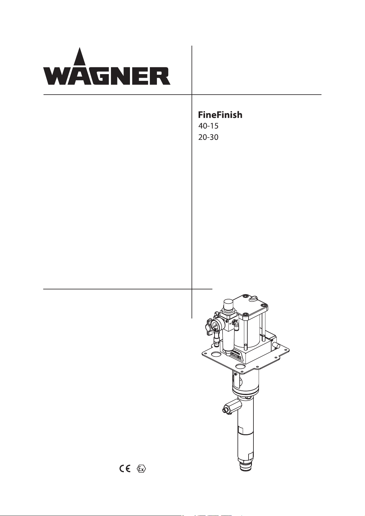
Piston Pumps
Flow Rate 15 cm3 - 30 cm
3
II 2G IIB c T3 X
B_04119
Page 2

Page 3

VERSION 03/2013 ORDER NUMBER DOC 2310799
OPERATING MANUAL
Contents
1 ABOUT THIS OPERATING MANUAL 5
1.1 Preface 5
1.2 Warnings, Notices, and Symbols in this Operating Manual 5
1.3 Languages 6
1.4 Abbreviations in the Text 6
2 CORRECT USE 7
2.1 Device Types 7
2.2 Type of Use 7
2.3 Use in an Explosion Hazard Area 7
2.4 Safety Parameters 7
2.5 Processible Materials 8
2.6 Reasonably Foreseeable Misuse 8
2.7 Residual Risks 9
3 IDENTIFICATION 10
3.1 Explosion Protection Identi cation 10
3.2 Identi cation X 10
4 GENERAL SAFETY INSTRUCTIONS 11
4.1 Safety Instructions for the Operator 11
4.1.1 Electrical Equipment 11
4.1.2 Sta Quali cations 11
4.1.3 Safe Work Environment 11
4.2 Safety Instructions for Sta 12
4.2.1 Safe Handling of WAGNER Spray Devices 12
4.2.2 Grounding the Device 13
4.2.3 Material Hoses 13
4.2.4 Cleaning 14
4.2.5 Handling Hazardous Liquids, Varnishes, and Paints 14
4.2.6 Touching Hot Surfaces 14
4.3 Use in Areas Subject to Explosion Hazards 15
4.3.1 Safety Regulations 15
4.3.2 Operation without Fluid 15
5 DESCRIPTION 16
5.1 Field of Application 16
5.1.1 Correct Use 16
5.1.2 Processible Materials 16
5.2 Scope of Delivery 17
5.3 Data 17
5.3.1 Materials of Paint-wetted Parts 17
5.3.2 Technical Data 18
5.3.3 Measurements and Connections for FineFinish 40-15 20
5.3.4 Measurements and Connections for FineFinish 20-30 21
5.3.5 Performance Diagrams 22
5.4 Function 25
5.4.1 Pump 25
5.4.2 Pressure Regulator Unit 26
5.4.3 Safety and Motor Pressure Relief Valve 27
5.4.4 Return Valve 27
3
Page 4

VERSION 03/2013 ORDER NUMBER DOC 2310799
OPERATING MANUAL
Contents
6 ASSEMBLY AND COMMISSIONING 28
6.1 Transportation 28
6.2 Storage 28
6.3 Assembling the Pump 29
6.4 Grounding 30
6.5 Commissioning 32
6.5.1 Safety Instructions 32
6.5.2 Filling with Separating Agent 34
6.5.3 Basic Flushing 35
7 OPERATION 36
7.1 Filling with Working Material 36
7.2 Work 37
7.2.1 Spraying 37
7.2.2 Pressure Relief/Work Interruption 38
7.2.3 Decommissioning and Cleaning 39
7.3 Long-term Storage 40
8 TROUBLESHOOTING AND RECTIFICATION 41
9 MAINTENANCE 42
9.1 High-pressure Hoses 43
9.2 Decommissioning 43
10 ACCESSORIES 44
11 SPARE PARTS 47
11.1 How Can Spare Parts Be Ordered? 47
11.2 Overview of the Components 48
11.2.1 Components for FineFinish 40-15 48
11.2.2 Components for FineFinish 20-30 49
11.3 Air Motor 50
11.3.1 Reversing Valve 53
11.4 Fluid sections 54
11.4.1 Fluid Section 15 54
11.4.2 Fluid Section 30 56
11.5 Air Regulator Set 58
11.6 Air Regulator Set for AirCoat Air 59
11.7 Trolley, 4" 60
11.8 4-Wheel Trolley 61
12 3+2 YEARS GUARANTEE FOR PROFESSIONAL FINISHING 62
12.1 Scope of Guarantee 62
12.2 Guarantee Period and Registration 62
12.3 Handling 62
12.4 Exclusion of Guarantee 63
12.5 Additional Regulations 63
12.6 CE Declaration of Conformity 65
12.7 Reference to German Regulations and Guidelines 65
4
Page 5
VERSION 03/2013 ORDER NUMBER DOC 2310799
OPERATING MANUAL
1 ABOUT THIS OPERATING MANUAL
1.1 PREFACE
The operating manual contains information about safely operating, maintaining, cleaning
and repairing the device.
The operating manual is part of the device and must be available to operating and service
sta .
Operating and service sta should be instructed according to the safety instructions.
The device may only be operated in compliance with this operating manual.
This equipment can be dangerous if it is not operated according to the instructions in this
operating manual.
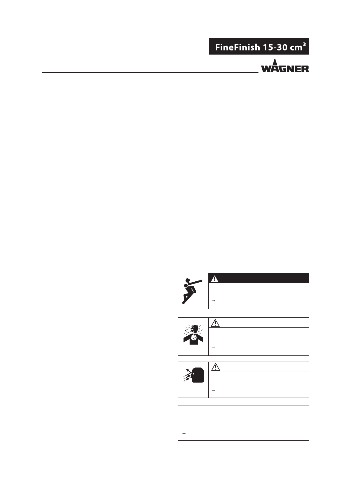
1.2 WARNINGS, NOTICES, AND SYMBOLS IN THIS OPERATING MANUAL
Warning instructions in this operating manual highlight particular dangers to users and
to the device and state measures for avoiding the hazard. These warning instructions fall
into the following categories:
DANGER
Danger - immediate risk of danger.
Non-observance will result in death or serious injury.
Warning - possible imminent danger.
Non-observance may result in death or serious injury.
Caution - a possibly hazardous situation.
Non-observance may result in minor injury.
This notice warns you of a hazard!
Possible consequences of not observing the warning instructions.
The signal word indicates the hazard level.
The following are measures which can be taken to prevent
the hazard and its consequences.
WARNING
This notice warns you of a hazard!
Possible consequences of not observing the warning instructions.
The signal word indicates the hazard level.
The following are measures which can be taken to prevent
the hazard and its consequences.
CAUTION
This notice warns you of a hazard!
Possible consequences of not observing the warning instructions.
The signal word indicates the hazard level.
The following are measures which can be taken to prevent
the hazard and its consequences.
Notice - a possibly hazardous situation.
Non-observance may result in material damage.
This notice warns you of a hazard!
Possible consequences of not observing the warning instructions. The signal word
indicates the hazard level.
The following are measures which can be taken to prevent the hazard and its
consequences.
NOTICE
Note - provides information about particular characteristics and how to proceed.
5
Page 6
VERSION 03/2013 ORDER NUMBER DOC 2310799
OPERATING MANUAL
1.3 LANGUAGES
The operating manual is available in the following languages:
Language Order No. Language Order No.
German 2310798 English 2310799
French 2310800 Spanish 2310803
Italian 2310802 Dutch 2310801
Portuguese 2310804 Swedish 2310806
Danish 2310805
1.4 ABBREVIATIONS IN THE TEXT
Number of pieces
Position
Marking in the spare parts lists
Order No. Order No.
No. Number
Double stroke
Stainless steel
Two components
6
Page 7
VERSION 03/2013 ORDER NUMBER DOC 2310799
OPERATING MANUAL
2 CORRECT USE
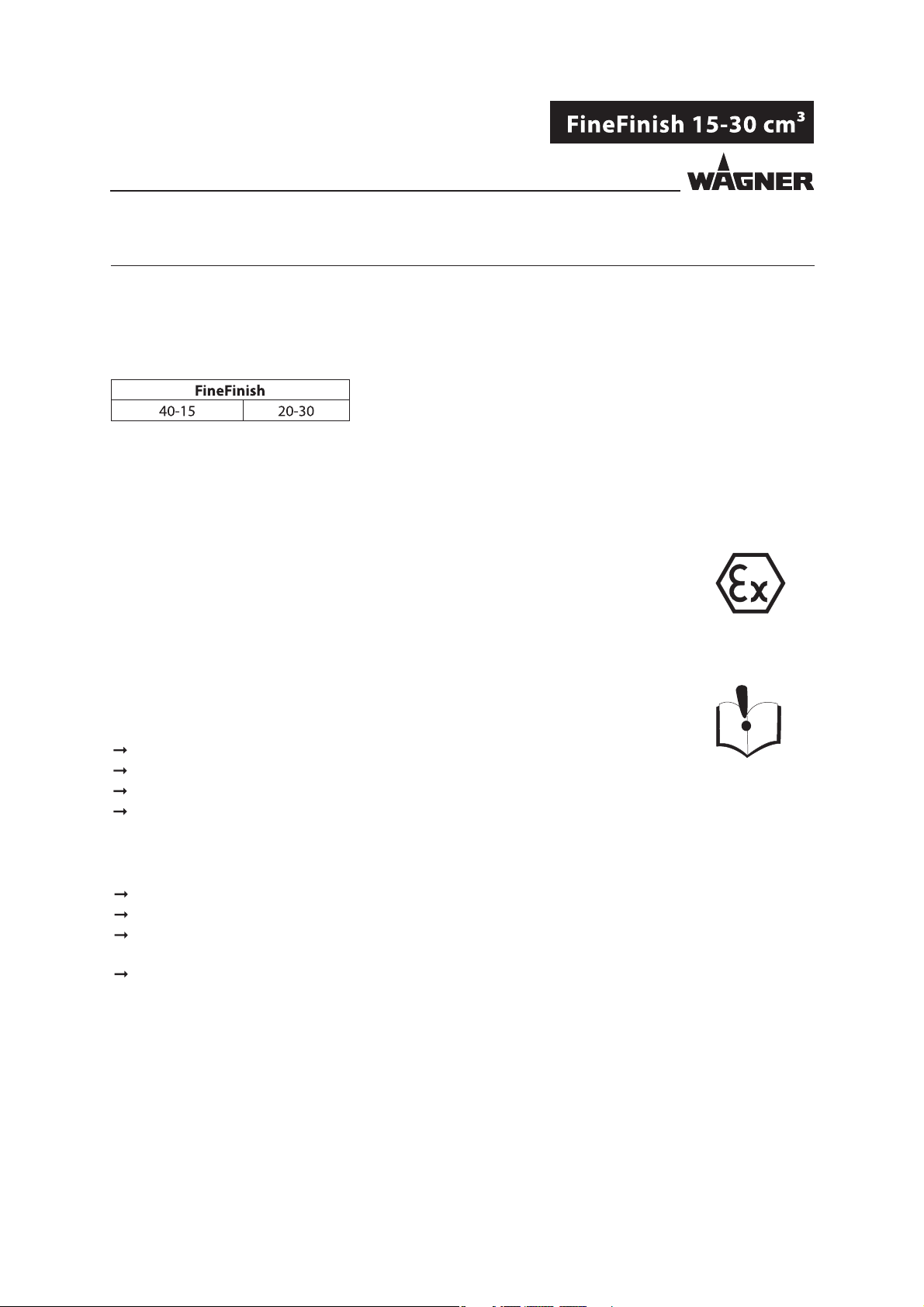
2.1 DEVICE TYPES
Pneumatic pump with spraypack:
2.2 TYPE OF USE
The device is suitable for processing liquid materials such as paints and varnishes in
accordance with their classi cation into explosion classes IIA or IIB.
2.3 USE IN AN EXPLOSION HAZARD AREA
The pneumatic pump can be employed in explosion hazard zones (Zone 1).
2.4 SAFETY PARAMETERS
WAGNER accepts no liability for any damage arising from incorrect use.
Use the device only to work with the materials recommended by WAGNER.
Only operate the device as a whole.
Do not deactivate safety xtures.
Use only WAGNER original spare parts and accessories.
The pneumatic pump may only be operated under the following conditions:
The operating sta must be trained on the basis of this operating manual.
The safety regulations listed in this operating manual must be observed.
The operating, maintenance, and repair information in this operating manual must
be observed.
The statutory requirements and accident prevention regulation standards in the
country of use must be observed.
7
Page 8
VERSION 03/2013 ORDER NUMBER DOC 2310799
OPERATING MANUAL
2.5 PROCESSIBLE MATERIALS
Fluid materials such as paints and varnishes.
NOTICE
Abrasive materials and pigments!
Greater wear of parts carrying the material.
Use the application-oriented model ( ow rate/cycle, material, valves, etc.) as
indicated in Chapter 5.3.2.
Check if the uids and solvents used are compatible with the pump construction
materials as indicated in Chapter 5.3.1.
2.6 REASONABLY FORESEEABLE MISUSE
The following is prohibited:
coating work pieces which are not grounded,
unauthorized conversions and modi cations to the pneumatic pump,
processing powder or similar coating materials, and
using defective components, spare parts, or accessories other than those described
in Chapter 10 of this operating manual.
The forms of misuse listed below may result in health issues and/or material damage:
use of powder as coating material and
incorrectly set values for processing.
Wagner pneumatic pumps are not designed for pumping food.
8
Page 9
VERSION 03/2013 ORDER NUMBER DOC 2310799
OPERATING MANUAL
2.7 RESIDUAL RISKS
Residual risks are risks which cannot be excluded even in the event of correct use.
If necessary, warning and prohibition signs at the relevant points of risk indicate residual
risks.
Residual risk Source Consequences Speci c measures Lifecycle phase
Skin contact with
paints and cleaning
agents
Paint in air outside
the de ned working
area
Handling of paints
and cleaning agents
Painting outside the
de ned working
area
Skin irritations, Wear protective
clothing,
allergies Observe safety data
sheets
Inhalation of
substances which are
hazardous to health
Observe working
and operating
instructions
Operation,
maintenance,
disassembly
Operation,
maintenance
9
Page 10
VERSION 03/2013 ORDER NUMBER DOC 2310799
OPERATING MANUAL
3 IDENTIFICATION
3.1 EXPLOSION PROTECTION IDENTIFICATION
As de ned in Directive 94/9/EC (ATEX 95), the device is suitable for use in areas where there
is an explosion hazard.
European Communities
Symbol for explosion protection
Device class II
Category 2 (Zone 1)
Ex-atmosphere gas
Explosion group
Constructional safety
Temperature class: maximum surface temperature < 200 °C; 392 °F
Special Notes (see Chapter 3.2)
3.2 IDENTIFICATION X
Maximum surface temperature
The maximum surface temperature of the piston pump can be reached if it runs dry.
Ensure that the piston pump is lled with su cient working or ushing agent.
Ensure that the separating agent container is lled with su cient separating agent.
Ignition temperature of the coating material
Ensure that the ignition temperature of the coating material is above the maximum
surface temperature.
Ambient temperature
The permissible ambient temperature is: +5 °C to +60 °C; +41 °C to 140 °F.
Medium supporting atomizing
To atomize the material, use only weakly oxidizing gases, e.g. air.
10
Page 11
VERSION 03/2013 ORDER NUMBER DOC 2310799
OPERATING MANUAL
4 GENERAL SAFETY INSTRUCTIONS
4.1 SAFETY INSTRUCTIONS FOR THE OPERATOR
Keep this operating manual at hand near the unit at all times.
Always follow local regulations concerning occupational safety and accident
prevention.
4.1.1 ELECTRICAL EQUIPMENT
Electrical devices and equipment
To be provided in accordance with the local safety requirements with regard to the
operating mode and ambient in uences.
May only be maintained by skilled electricians or under their supervision.
Must be operated in accordance with the safety regulations and electrotechnical
regulations.
Must be repaired immediately in the event of problems.
Must be decommissioned if they pose a hazard.
Must be de-energized before work is commenced on active parts. Inform sta about
planned work. Observe electrical safety regulations.
4.1.2 STAFF QUALIFICATIONS
Ensure that the device is operated and repaired only by trained persons.
4.1.3 SAFE WORK ENVIRONMENT
Ensure that the oor in the working area is electrically conductive in accordance with
EN61340-4-1 (resistance must not exceed 100 Mohm).
Ensure that all persons within the working area wear electrostatically conductive shoes.
Footwear must comply with EN 20344. The measured insulation resistance must not
exceed 100 Mohm.
Ensure that during spraying, persons wear electrically conductive gloves. The grounding
takes place via the spray gun handle.
If protective clothing is worn, including gloves, it has to comply with EN1149-5. The
measured insulation resistance must not exceed 100 Mohm.
Paint mist extraction systems must be tted on site according to local regulations.
Ensure that the following components of a safe working environment are available:
– Material/air hoses adapted to the working pressure.
– Personal safety equipment (breathing and skin protection).
Ensure that there are no ignition sources such as naked ames, sparks, glowing wires,
or hot surfaces in the vicinity. Do not smoke.
11
Page 12
VERSION 03/2013 ORDER NUMBER DOC 2310799
OPERATING MANUAL
4.2 SAFETY INSTRUCTIONS FOR STAFF
Always follow the information in these instructions, particularly the general safety
instructions and the warning instructions.
Always follow local regulations concerning occupational safety and accident
prevention.
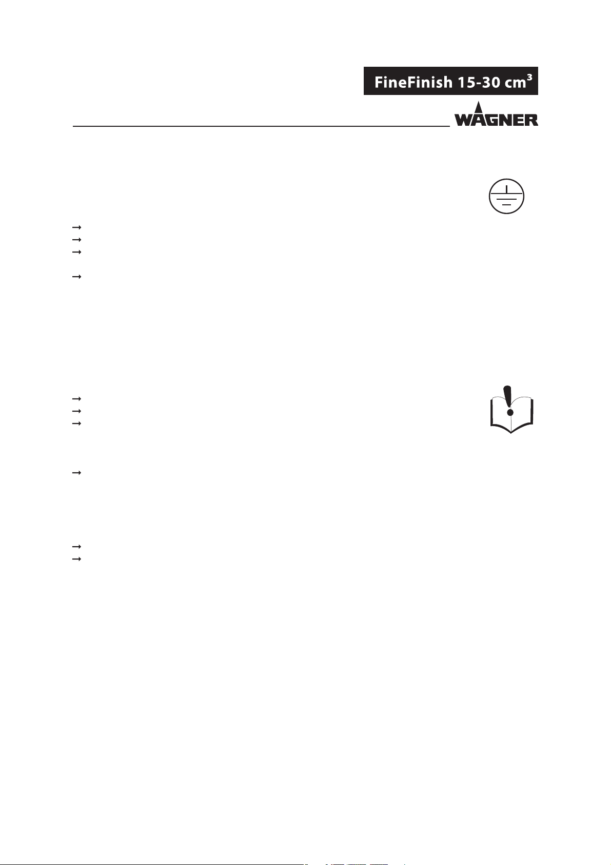
4.2.1 SAFE HANDLING OF WAGNER SPRAY DEVICES
The spray jet is under pressure and can cause dangerous injuries.
Avoid injection of paint or cleaning agents:
Never point the spray gun at people.
Never reach into the spray jet.
Before all work on the device, in the event of work interruptions and functional faults:
– Switch o the energy/compressed air supply.
– Relieve the pressure from the spray gun and device.
– Secure the spray gun against actuation.
– In the event of functional faults: remedy the fault as described in the " Troubleshooting"
chapter.
The liquid emitters are to be checked for safe working conditions by an expert
(e.g. Wagner Service Technician) as often as necessary or at least every 12 months,
in accordance with the guidelines for liquid emitters (ZH1/406 and BGR500 Part 2
Chapter2.36).
– For shut down devices, the examination can be suspended until the next commissioning.
Carry out the work steps as described in the "Pressure Relief/Work Interruptions"
chapter:
– if pressure relief is required.
– if the spraying work is interrupted or stopped.
– before the device is cleaned on the outside, checked, or serviced.
– before the spray nozzle is installed or cleaned.
In the event of skin injuries caused by paint or cleaning agents:
Note down the paint or cleaning agent that you have been using.
Consult a doctor immediately.
Avoid danger of injury through recoil forces:
Ensure that you have firm footing when operating the spray gun.
Only hold the spray gun brie y in a position.
12
Page 13
VERSION 03/2013 ORDER NUMBER DOC 2310799
OPERATING MANUAL
4.2.2 GROUNDING THE DEVICE
In order to avoid electrostatic charging of the device, the device must be grounded.
Friction, owing liquids, and air or electrostatic coating processes create charges. Flames
or sparks can form during discharge.
Ensure that the device is grounded for every spraying operation.
Ground the work pieces to be coated.
Ensure that all persons inside the working area are grounded, e.g. that they are wearing
electrostatically conductive shoes.
Wear electrostatically conductive gloves when spraying. The grounding takes place via
the spray gun handle.
4.2.3 MATERIAL HOSES
Ensure that the hose material is chemically resistant to the sprayed materials.
Ensure that the material hose is suitable for the pressure generated in the device.
Ensure that the following information can be seen on the high-pressure hose:
– Manufacturer
– Permissible operating overpressure
– Date of manufacture
Make sure that the hoses are laid only in suitable places. In no case, should hoses be laid
in the following places:
– in high-traffic areas,
– on sharp edges,
– on moving parts, or
– on hot surfaces
Make sure that the hoses are never used to pull or move the equipment.
The electrical resistance of the complete high-pressure hose must be less than 1 Mohm.
Several liquids have a high expansion coe cient. In some cases their volume can rise with
consequent damage to pipes, ttings, etc. and cause uid leakage.
When the pump sucks liquid from a closed container, ensure that air or suitable gas can
enter the container to avoid a vacuum being generated in the container itself. Thus a
negative pressure is avoided. The vacuum could implode the container (squeeze) and can
cause it to break. The container would leak and the liquid would ow out.
The pressure created by the pump is a multiplication of the inlet air pressure.
13
Page 14
VERSION 03/2013 ORDER NUMBER DOC 2310799
OPERATING MANUAL
4.2.4 CLEANING
De-energize the device electrically.
Disconnect the pneumatic supply line.
Relieve the pressure from the device.
Ensure that the flash point of the cleaning agent is at least 5 K above the ambient
temperature.
To clean, use cloths and brushes moistened with solvent. Never use hard objects or
spray on cleaning agents with a gun.
Preferably, non-combustible cleaning agents should be used.
An explosive gas/air mixture forms in closed containers.
When cleaning devices with solvents, never spray into a closed container.
Only use electrically conductive containers for cleaning liquids.
The containers must be grounded.
4.2.5 HANDLING HAZARDOUS LIQUIDS, VARNISHES, AND PAINTS
When preparing or working with paint and when cleaning the device, follow the
working instructions of the manufacturer of the paints, solvents, and cleaning agents
being used.
Take the speci ed protective measures. In particular, wear safety goggles, protective
clothing, and gloves, as well as hand protection cream if necessary.
Use a mask or a breathing apparatus if necessary.
For su cient health and environmental safety: operate the device in a spray booth or
on a spraying wall with the ventilation (extraction) switched on.
Wear suitable protective clothing when working with hot materials.
4.2.6 TOUCHING HOT SURFACES
Only touch hot surfaces if you are wearing protective gloves.
When operating the device with a coating material with a temperature of >43°C;109°F:
- Identify the device with a warning label "Warning - hot surface".
Order No.
9998910 Instruction label
9998911 Protection sticker
Note: Order the two stickers together.
14
Page 15
VERSION 03/2013 ORDER NUMBER DOC 2310799
OPERATING MANUAL
4.3 USE IN AREAS SUBJECT TO EXPLOSION HAZARDS
The pneumatic pump may be used in areas subject to explosion hazards. The following
safety regulations must be observed and followed.
4.3.1 SAFETY REGULATIONS
Safe handling of WAGNER spray devices
Mechanical sparks can form if the device comes into contact with metal.
In an explosive atmosphere:
Do not knock or push the unit against steel or rusty iron.
Do not drop the device.
Only use tools that are made of a permitted material.
Ignition temperature of the pumped material
Check that the ignition temperature of the pumped material is higher than the max.
allowable surface temperature.
Medium supporting atomizing
To atomize the material, use only weakly oxidizing gases, e.g. air.
Surface spraying, electrostatics
Do not spray device parts using electrostatic equipment.
Cleaning
If there are deposits on the surfaces, the device may form electrostatic charges. Flames or
sparks can form during discharge.
Remove deposits from the surfaces to maintain conductivity.
Only use a damp cloth to clean the device.
4.3.2 OPERATION WITHOUT FLUID
Avoid running the pump so that it sucks in air (without uid inside). The air, combined with
the vapor of ammable uids, can generate internal areas with an explosion hazard.
Periodically check that the pump is working smoothly, paying special attention to the
presence of air in the pumped uid, which may be caused by damaged packings.
Avoid operating the pump with damaged packings.
Ensure that the separating agent container is lled with su cient separating agent.
15
Page 16
VERSION 03/2013 ORDER NUMBER DOC 2310799
OPERATING MANUAL
5 DESCRIPTION
5.1 FIELD OF APPLICATION
5.1.1 CORRECT USE
The pneumatic piston pump is suitable for conveying and processing (AirCoat technique)
liquid materials in accordance with Chapter 5.1.2.
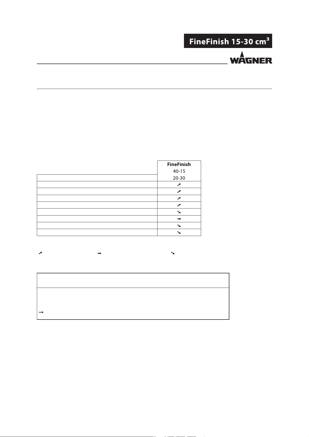
5.1.2 PROCESSIBLE MATERIALS
Application
Water-based materials
Solvent-based materials
Low viscosity (<40 sec. DIN No. 4)
Medium viscosity (40 to 60 sec. DIN No. 4)
High viscosity ( >60 sec. DIN No. 4)
UV - sensitive materials
Shear sensitive materials
Humidity sensitive materials
Legend
recommended limited suitability less suitable
NOTICE
Abrasive materials and pigments!
Greater wear of parts carrying the material.
Use suitable combinations of devices (packings, valves, etc.)
16
Page 17
VERSION 03/2013 ORDER NUMBER DOC 2310799
OPERATING MANUAL
5.2 SCOPE OF DELIVERY
Pneumatic piston pump consisting of:
- Fluid section
- Air motor
- Connection elements
Separating agent 250 ml Order No.: 9992504
Conformity certi cate GM2000W see Chapter 12
Operating manual, German Order No.: 2310798
Operating manual in the local language see Chapter 1
The delivery note shows the exact scope of delivery.
Accessories: see Chapter 10.
5.3 DATA
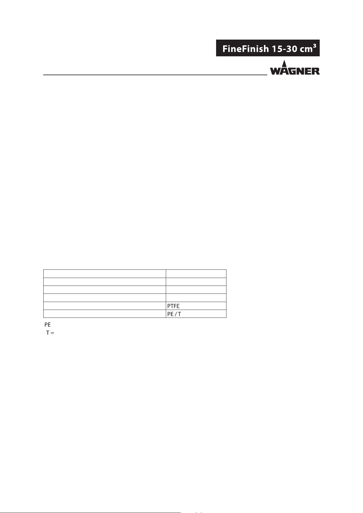
5.3.1 MATERIALS OF PAINTWETTED PARTS
Pump housing Stainless steel
Piston Stainless steel
Valve balls Stainless steel
Valve seats Stainless steel
Static seals
Packings
Ultra high molecular weight polyethylene
=
PTFE
17
Page 18
VERSION 03/2013 ORDER NUMBER DOC 2310799
OPERATING MANUAL
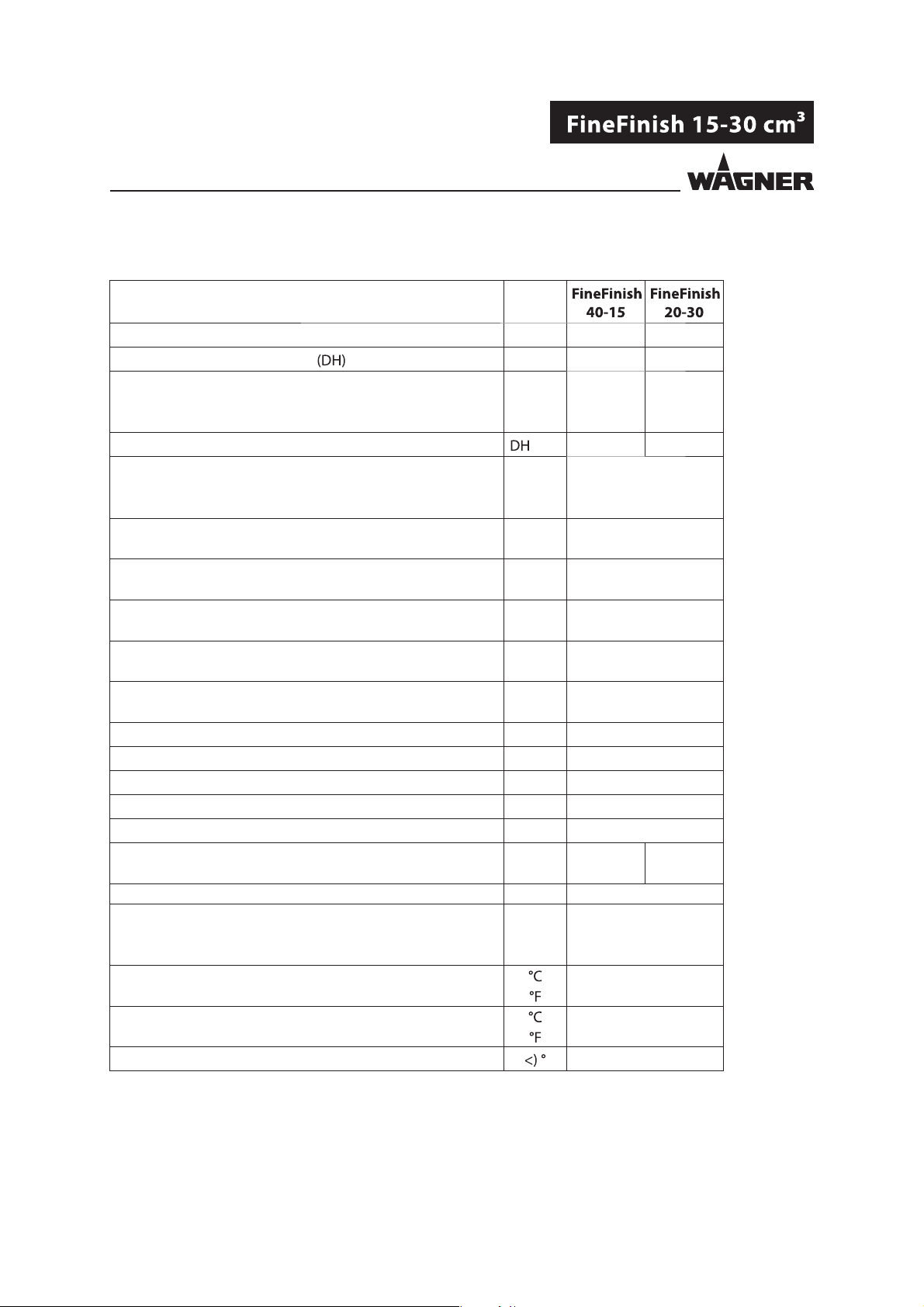
5.3.2 TECHNICAL DATA
Description Units
Pump ratio 40:1
Volume ow per double stroke cm; cc 15 30
Maximum operating overpressure MPa 25.0 16.0
bar 250 160
psi 3626 2320
Maximum possible strokes in operation /min 60 60
Minimum/maximum air inlet pressure MPa 0.2-0.8
bar 2-8
psi 28-116
Ø air inlet connection (inside thread) mm 8.0
inch 0.31
Minimum Ø of the compressed air supply line mm 9.0
inch 0.35
Air consumption at 0.6 MPa; 6 bar; 87 psi per double stroke nl 3.9
scf 0.14
Air motor piston diameter mm 80
inch 3.15
Air motor piston stroke mm 60
inch 2.4
Sound pressure level at maximum permissible air pressure* dB(A) 72
Sound pressure level at 0.6 MPa; 6 bar; 87 psi air pressure* dB(A) 69
Sound pressure level at 0.4 MPa; 4 bar; 58 psi air pressure* dB(A) 65
Material inlet (outside thread) mm M36x2
Material outlet (outside thread) inch NPS 1/4"
Weight kg 9 11
lb 19.8 24.7
Material pH value pH 3.5 ÷ 9
Maximum material pressure at pump inlet MPa 2
bar 20
psi 90
Material temperature
Ambient temperature +5 ÷ +60
Allowable inclination for operation ± 10
20:1
+5 ÷ +80
+41 ÷ +176
+41 ÷ +140
* A-rated sound pressure level measured at 1 m distance, LpA1m, in accordance with DIN EN 14462: 2005.
18
Page 19
VERSION 03/2013 ORDER NUMBER DOC 2310799
OPERATING MANUAL
WARNING
Outgoing air containing oil!
Risk of poisoning if inhaled.
Air motor switching problems.
Provide compressed air free from oil and water
(Quality Standard 5.5.4 in accordance with ISO 8573.1)
5.5.4 = 40 m / +7 / 5 mg/m³.
19
Page 20
VERSION 03/2013 ORDER NUMBER DOC 2310799
OPERATING MANUAL
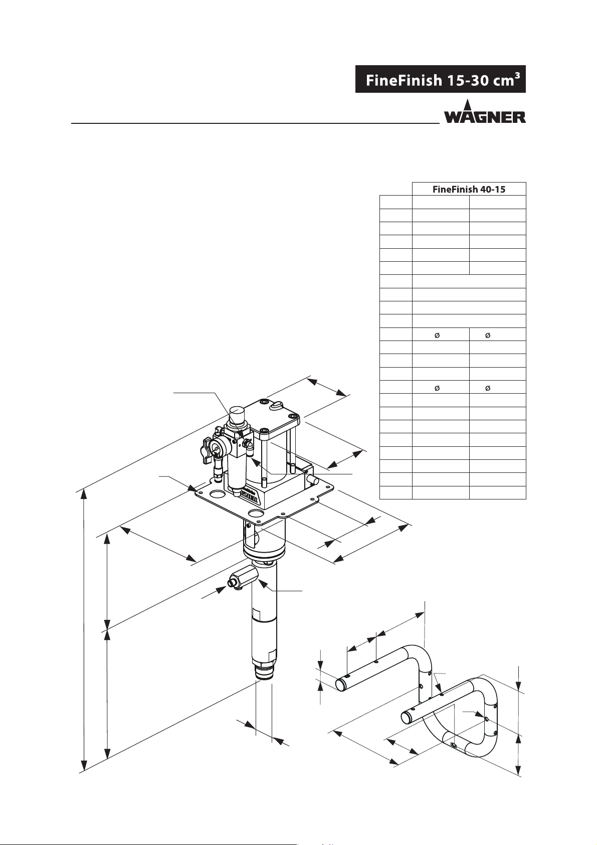
5.3.3 MEASUREMENTS AND CONNECTIONS FOR FINEFINISH 4015
A
H1
B
L
H2
mm inch
A 104 4.09
B 108.5 4.27
C 621 24.45
D 276.5 10.89
E 134 5.28
F1 G 1/4"
F2 NPS 1/4"
G M36x2
H1 G 1/4"
H2 8 0.31
I 210 8.27
J 207 8.15
K 86 3.39
L 7 0.28
M 182 7.17
N 80 3.15
O 106 4.17
P 96.5 3.8
Q ø 9 ø 0.35
R ø 7 ø 0.28
S 149 5.87
T ø 25 ø 1
K
J
I
E
F1
F2
S
Wall mount
N
C
T
R
D
Q
O
G
B_04120
M
M/2
P
20
Page 21
VERSION 03/2013 ORDER NUMBER DOC 2310799
OPERATING MANUAL
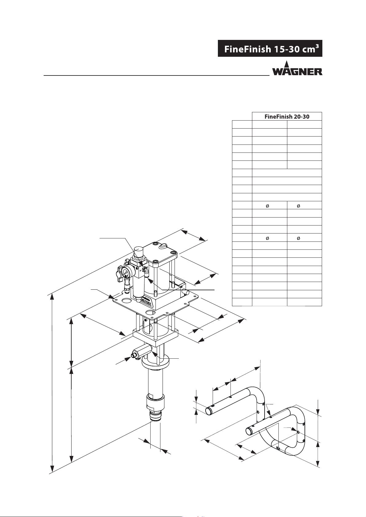
5.3.4 MEASUREMENTS AND CONNECTIONS FOR FINEFINISH 2030
A
H1
B
L
H2
mm inch
A 104 4.09
B 108.5 4.27
C 643 25.3
D 201 7.91
E 134.5 5.3
F1 G 3/8"
F2 NPS 1/4"
G M36x2
H1 G 1/4"
H2 8 0.31
I 210 8.27
J 207 8.15
K 80 3.15
L 7 0.28
M 182 7.17
N 80 3.15
O 106 4.17
P 96.5 3.8
Q ø 9 ø 0.35
R ø 7 ø 0.28
S 149 5.87
T ø 25 ø 0.98
J
K
I
E
F1
F2
S
Wall mount
N
T
C
D
B_04100
G
M
M/2
R
Q
O
P
21
Page 22

VERSION 03/2013 ORDER NUMBER DOC 2310799
OPERATING MANUAL
5.3.5 PERFORMANCE DIAGRAMS
Example
Stroke frequency
BAR
BAR
BAR
Material pressure bar (MPa) psi
"?
Water delivery rate l/min <gpm>
/min
BAR
BAR
BAR
Air consumption nl/min <scfm>
22
Page 23

VERSION 03/2013 ORDER NUMBER DOC 2310799
OPERATING MANUAL
Diagram of FineFinish 40-15
bar (MPa)
<psi>
300 (30)
<4350>
240 (24)
<3480>
180 (18)
<2610>
120 (12)
<1740>
60 (6)
<870>
Material pressure
C_00054
Stroke frequency /min
10 20 30 40 50 60
0
A
B
C
0
0.60
0.45
0.30
0.15
0
<0.04>
<0.08>
<0.12>
<0.16>
Material ow - water
A = 8 bar; 0.8 MPa; 116 psi air pressure
B = 6 bar; 0.6 MPa; 87 psi air pressure
C = 4 bar; 0.4 MPa; 58 psi air pressure
0.75
<0.20>
A
B
C
0.90
<0.24>
nl/min
<scfm>
300
<11>
240
<8>
180
<6>
120
<4>
60
<2>
0
l/min
<gpm>
Air consumption
Diagram of FineFinish 20-30
bar (MPa)
Material pressure
<psi>
150 (15)
<2176>
120 (12)
<1740>
90 (9)
<1305>
60 (6)
<870>
30 (3)
<435>
0
0
0
C_00142
Stroke frequency /min
10 20 30 40 50 60
A
A
B
B
C
C
1.80
1.50
1.20
0.90
0.60
0.30
<0.08>
<0.16>
<0.23>
<0.31>
<0.39>
<0.47>
Material ow - water
A = 8 bar; 0.8 MPa; 116 psi air pressure
B = 6 bar; 0.6 MPa; 87 psi air pressure
C = 4 bar; 0.4 MPa; 58 psi air pressure
nl/min
<scfm>
350
<12.5>
280
<10>
210
<7.5>
140
<5>
70
<2.5>
0
l/min
<gpm>
Air consumption
23
Page 24

VERSION 03/2013 ORDER NUMBER DOC 2310799
OPERATING MANUAL
24
Page 25

VERSION 03/2013 ORDER NUMBER DOC 2310799
OPERATING MANUAL
5.4 FUNCTION
5.4.1 PUMP
1 Air motor
2 Air inlet
3 Mounting ange
4 Separating uid
container
5 Material outlet
6 Fluid section
7 Material inlet
8 Grounding connection
9 Reversing valve
10 Safety valve
(air motor ventilation)
11 Air pressure regulator
12 Ball valve
13 Air outlet to the
reversing valve
14 Air inlet into the
reversing valve
Function principle
The piston pump is driven with compressed air (11). This compressed air moves the air piston up and down in
the air motor (1) and it also moves the associated pump piston up and down in the uid section (6). At the end
of each stroke, the compressed air is redirected by a reversing valve (9).
The working material is sucked up during the upwards stroke and is continuously conveyed towards the
material outlet (5) in both stroke directions.
1
8
4
10
6
B_04121
7
11
2
3
9
8
13
12
5
14
7
Air motor
The air motor (1) with its pneumatic reverse (9) does not require pneumatic oil.
The compressed air is fed to the motor via an air regulator (11) and the ball valve (12).
The air motor is to be equipped with a safety valve (10) in accordance with Chapter 5.4.3. The safety valve (10)
has been set and sealed at the factory. In case of pressures over and above the permissible operating pressure,
the valve, which is held with a spring, automatically opens and releases the excess pressure.
WARNING
Overpressure!
Risk of injury from bursting components.
Never change the safety valve setting.
Fluid section (6)
The uid section has been designed as a piston pump with exchangeable ball valves. The
pump piston runs in two xed packings which are self-adjusting by means of a pressure
spring, thus resulting in a long service life.
Between the air motor and the uid section there is a separating agent cup (4) for holding
the separating agent.
25
Page 26

VERSION 03/2013 ORDER NUMBER DOC 2310799
OPERATING MANUAL
5.4.2 PRESSURE REGULATOR UNIT
1 Pressure regulator
2 Ball valve
3 Pressure gage (air inlet pressure)
4 Pressure gage for AirCoat air (option)
5 Compressed air inlet
6 Pressure regulator AirCoat (option)
7 Safety and motor pressure relief valve
2
1
3
7
Ball valve positions:
4
6
2
7
1
3
5
5
B_04122
1 Open: working position
2 Closed: the air motor may still be
under pressure.
open
1
2
closed
B_04123
26
Page 27

VERSION 03/2013 ORDER NUMBER DOC 2310799
OPERATING MANUAL
5.4.3 SAFETY AND MOTOR PRESSURE RELIEF VALVE
Safety valve
The safety valve (10) has been factory adjusted so as to ensure that if pressure exceeds the
permitted operating pressure, the valve, which is held with a spring, automatically opens
and releases the excess pressure.
As well as handling pressure limits, the valve is also used as a pressure relief valve for the
air motor.
10
Pressure relief of the air motor:
1 Close ball valve (2).
2 Pull back the ring on the safety
valve (10) and hold it there until
the pressure in the air motor has
been equalized.
WARNING
Overpressure!
Risk of injury from bursting components.
Never change the safety valve setting.
5.4.4 RETURN VALVE
10
2
B_04124
So that the complete pressure relief of the pump can be
performed (see Chapter 7.2.2), the installation of a return
valve is mandatory.
The suitable return valves (ball valves), return pipes and hoses
for the device can be found in the accessories list.
1 Material outlet
2 Return valve
3 Material return line
2
1
B_04075
3
27
Page 28

VERSION 03/2013 ORDER NUMBER DOC 2310799
OPERATING MANUAL
6 ASSEMBLY AND COMMISSIONING
6.1 TRANSPORTATION
The pump can be moved on a trolley or manually without lifting equipment.
6.2 STORAGE
Store the pump in a closed and dry environment.
Thoroughly clean the pump, if a long-term decommissioning is planned.
When resuming pump operation, proceed as described in the following sections.
WARNING
Discharge of electrostatically charged components in atmospheres
containing solvents!
Explosion hazard from electrostatic sparks.
Only use a damp cloth to clean the pump.
28
Page 29

VERSION 03/2013 ORDER NUMBER DOC 2310799
OPERATING MANUAL
6.3 ASSEMBLING THE PUMP
Notice
This pump can be used as part of a spraying system for Airless
or AirCoat applications. Individual supplement components
for this pump can be found in the Wagner Accessories
Catalogue, or can be put together with the Spraypack
Con gurator. The nozzles must be selected according to the
gun instructions. In the case of spraypack orders, the pumps
(1) are already pre-mounted on a trolley (6) or on a stand at
the factory.
Procedure:
1 Mount pump (1) on stand, trolley (6), or wall mount.
2 Mount an AirCoat system with the pressure regulator
(7) and secure the thread at the air inlet to the pump
(1) with Loctite 270.
3 Mount suction system (5).
4 Mount the return valve (8) for pressure relief or
material circulation.
5 Mount return tube (4) or return hose.
6 Connect the high pressure hose (2) and gun (3) in
accordance with the gun operating manual.
Example:
Airless system
3
2
5
Example:
AirCoat system
6
1
8
4
B_04076
7
WARNING
Inclined ground!
Risk of accidents if the device rolls away/falls.
3
1
2
8
4
5
6
B_04077
29
Page 30

VERSION 03/2013 ORDER NUMBER DOC 2310799
OPERATING MANUAL
6.4 GROUNDING
WARNING
Discharge of electrostatically charged components in atmospheres
containing solvents!
Explosion hazard from electrostatic sparks.
Only use a damp cloth to clean the piston pump.
WARNING
Heavy paint mist if grounding is insu cient!
Danger of poisoning.
Insu cient paint application quality.
Ground all device components.
Ground the work pieces to be coated.
Grounding scheme (example)
Note for the sprayer
Safety shoes and gloves, if
used, must be electrostatically
conductive.
Paint container
Work piece
Conveyor
Spraying stand
R max < 1 M Ω
B_00304
Floor, electrostatically conductive
30
Page 31

VERSION 03/2013 ORDER NUMBER DOC 2310799
OPERATING MANUAL
Cable cross sections
Pump 4 mm;
Paint container 6 mm;
Conveyor 16 mm;
Spray booth 16 mm;
Spraying stand 16 mm;
Procedure:
1 Screw on grounding cable with eye.
2 Clamp the grounding cable clip to a grounding connection on site.
3 Ground the material (paint) container to an on-site grounding connection.
4 Ground the other parts of the system to an on-site grounding connection.
Grounding cable
B_04127
31
Page 32

VERSION 03/2013 ORDER NUMBER DOC 2310799
OPERATING MANUAL
6.5 COMMISSIONING
6.5.1 SAFETY INSTRUCTIONS
Before carrying out any work, the following points must be observed in accordance with
the operating manual:
- Observe all safety regulations in accordance with Chapter 4.
- Carry out commissioning properly.
WARNING
High-pressure spray jet!
Danger to life from injecting paint or solvent.
Never reach into the spray jet.
Never point the spray gun at people.
Consult a doctor immediately in the event of skin injuries caused
by paint or solvent. Inform the doctor about the paint or solvent
used.
Never seal defective high-pressure parts; instead relieve the
pressure from them and replace them.
WARNING
Toxic and/or ammable vapor mixtures!
Risk of poisoning and burns.
Operate the device in a spray booth approved for the working
materials.
-or Operate the device on an appropriate spraying wall with the
ventilation (extraction) switched on.
Observe national and local regulations for the outgoing air
speed.
WARNING
Gas mixtures can explode if there is an incompletely filled pump!
Danger to life from ying parts.
Ensure that the pump and suction system are always completely
lled with ushing agent or working medium.
Do not spray the device empty after cleaning.
32
Page 33

VERSION 03/2013 ORDER NUMBER DOC 2310799
OPERATING MANUAL
Before every start-up, the following points should be observed as laid down in the
operating manual:
- Check the permissible pressures.
- Check all connecting parts for leaks.
- Check hoses for damage.
It should be ensured that the device is in the following state before carrying out any work
on it:
- Interrupt the air supply (2).
- Depressurize the air motor (pull the ring on the safety valve (10)).
- Relieve the pressure from the uid section.
10
closed
10
2
open
EMERGENCY STOP
In the case of unforeseen occurrences
the ball valve (2) should be closed
immediately.
Open the safety valve (10) and relieve the
material-conveying parts completely of
pressure via the return valve (3).
B_04124
2
C_00157
3
B_04078
33
Page 34

VERSION 03/2013 ORDER NUMBER DOC 2310799
OPERATING MANUAL
6.5.2 FILLING WITH SEPARATING AGENT
NOTICE
Piston pump runs dry!
High wear/damage to the packings.
Paint or solvent can escape if the seals are dry.
Ensure that the separating agent container is lled with su cient separating agent.
Filling level 2 cm; 0.8 inch under the cup edge.
Pour the supplied separating agent into the intended opening.
Filling level: 2 cm; 0.8 inch under the cup edge
Separating agent: See accessories.
Notice
Maximum permissible inclination of pump for moving, transportation
etc. after lling it with separating agent ± 30°.
The pump must be vertical during operation.
B_04130
34
Page 35

VERSION 03/2013 ORDER NUMBER DOC 2310799
OPERATING MANUAL
6.5.3 BASIC FLUSHING
Before each basic ushing, the nozzle must be removed from the pistol. The data in the
gun's operating manual are to be observed.
With AirCoat systems, carry out the basic ushing of the system without atomizing air (8)
1 Place empty container (5) under return tube (4).
2 Place suction hose (7) in the container with ushing agent (6).
3 Open return valve (3).
4 Slowly open the ball valve (2).
5 Adjust the air pressure on the pressure regulator (1) so that the pump runs smoothly.
6 Flush the system until clean ushing agent ows into the container (5).
7 Close ball valve (2).
8 Close return valve (3).
9 Point the gun (9), without nozzle, into container (5) and open it.
10 Slowly open the ball valve (2).
11 Rinse until clean ushing agent ows from the gun.
12 Close ball valve (2).
13 Relieve the system pressure, either by opening the return valve (3) or via the trigger
on the gun (9).
14 When there is no pressure remaining in the system, close the gun (9) or the return
valve (3).
15 Secure the gun.
16 Dispose of the contents of the container (5) according to the local regulations.
.
closed
open
1
8
2
7
3
4
6
5
9
B_04079
35
Page 36

VERSION 03/2013 ORDER NUMBER DOC 2310799
OPERATING MANUAL
7 OPERATION
7.1 FILLING WITH WORKING MATERIAL
Note:
Before each lling, the nozzle must be removed from the pistol. The data in the gun's
operating manual are to be observed.
In case of AirCoat systems, carry out the lling of the system without atomizing air (8).
1 Place empty container (5) under return tube (4).
2 Place suction hose (7) in the container with working material (6).
3 Open return valve (3).
4 Slowly open the ball valve (2).
5 Adjust the air pressure on the pressure regulator (1) so that the pump runs smoothly.
6 Spray until clean working material ows into the container (5).
7 Close ball valve (2).
8 Close return valve (3).
9 Point the gun (9), without nozzle, into container (5) and open it.
10 Slowly open the ball valve (2).
11 Spray until clean working material ows from the gun (9).
12 Close ball valve (2).
13 Relieve the system pressure, either by opening the return valve (3) or via the trigger
on the gun (9).
14 When there is no pressure remaining in the system, close the gun (9) or the return
valve (3).
15 Secure the gun.
16 Dispose of the contents of the container (5) according to the local regulations.
36
Page 37

VERSION 03/2013 ORDER NUMBER DOC 2310799
OPERATING MANUAL
7.2 WORK
7.2.1 SPRAYING
System example for
the AirCoat procedure
closed
open
7
6
1 Secure the gun and insert the nozzle into the gun.
2 Close return valve (3).
3 Slowly open the ball valve (2).
4 Set required working pressure on the pressure regulator (1).
5 Optimize the spraying results according to the data in the gun operating manual.
6 Start work process.
2
8
1
9
3
4
5
B_04080
37
Page 38

VERSION 03/2013 ORDER NUMBER DOC 2310799
OPERATING MANUAL
7.2.2 PRESSURE RELIEF/WORK INTERRUPTION
Pressure relief of the material
1 Close the spray gun.
2 Close ball valve (2).
3 Relieve the system pressure, either by opening the gun or by opening the return
valve (3).
4 Close and secure gun.
5 Open and close the return valve (3) to completely depressurize the system.
Pressure relief of the air (in case of longer work interruptions)
1 Carry out pressure relief of the material (as mentioned above).
2 Ensure that the ball valve (2) is closed.
3 Pull back the ring on the safety valve (10) and hold it there until the pressure in the
air motor has been equalized.
10
10
B_04124
If the system has been used with 2-component materials:
2
NOTICE
Hardened working material in the spraying system when two-component material
is processed!
Destruction of pump and injection system.
Follow the manufacturer‘s processing rules, particularly regarding the pot life.
Flush thoroughly before the end of the pot life.
The pot life is decreased by warmth.
38
Page 39

VERSION 03/2013 ORDER NUMBER DOC 2310799
OPERATING MANUAL
7.2.3 DECOMMISSIONING AND CLEANING
Notice
The device should be cleaned for maintenance purposes. Ensure that no remaining
material dries and sticks.
Procedure:
1 Carry out pressure relief of the material and air -> Chapter 7.2.2.
2 Basic cleaning -> carry out the steps in Chapter 6.5.3.
3 Maintain the gun according to the operating manual.
4 Clean and check the suction system and the suction lter.
5 Clean the outside of the system.
WARNING
Brittle lter pressure regulator!
The container on the lter pressure regulator becomes brittle
through contact with solvents and can burst.
Flying parts can cause injury.
Do not clean the container on the lter pressure regulator with
solvent.
6 Put the whole system back together.
7 Check the level of the separating agent -> Chapter 6.5.2.
8 Fill the system with ushing agent as laid down in Chapter 7.1 "Filling with Working
Material".
WARNING
Gas mixtures can explode if there is an incompletely filled
pump!
Danger to life from ying parts.
Ensure that the pump and suction system are always completely
lled with ushing agent or working medium.
Do not spray the device empty after cleaning.
39
Page 40

VERSION 03/2013 ORDER NUMBER DOC 2310799
OPERATING MANUAL
7.3 LONGTERM STORAGE
When storing the device for longer periods of time, it is necessary to thoroughly clean it
and protect it from corrosion. For the last rinse, replace the water or solvent in the material
pump with a suitable preservative. Fill separating agent cup with separating agent. Store
pump vertically.
Procedure:
1 Chapter 7.2.3 "Decommissioning and Cleaning", perform points 1 to 7.
2 Flush with preservative according to Chapter 6.5.3 and paint supplier's instructions.
3 If the discharge duct is to be removed, seal material outlet with plug.
4 If the suction system is to be removed, seal material inlet with plug.
40
Page 41

VERSION 03/2013 ORDER NUMBER DOC 2310799
OPERATING MANUAL
8 TROUBLESHOOTING AND RECTIFICATION
Problem Cause Remedy
Pump does not work. Air motor does not work or stops. Open and close ball valve on the pressure
regulator unit or brie y disconnect
compressed air supply.
No pressure indication on the
pressure gage
(air pressure regulator defective).
Spray nozzle is clogged. Clean the nozzle according to the instructions.
Insu cient compressed air supply. Check compressed air supply.
Filter insert in spray gun is clogged. Clean the parts and use a suitable working
Fluid section or high pressure hose
are blocked (e.g., two-component
material hardened).
Sometimes, the pump stops at a
switching point.
Poor spray pattern See gun instructions.
Irregular pump
operation: spray jet
collapses (pulsation).
The pump runs evenly,
does not however,
suck up material.
Pump runs when the
gun is closed.
Air motor is iced up. There is a lot of condensation water
Viscosity is too high. Thin spraying material.
Spraying pressure is too low. Increase air inlet pressure.
Valves are clogged. Clean pump, if necessary leave it to soak in
Foreign body in suction valve. Dismount suction valve housing, clean, and
Diameter of compressed air line too
small.
Valves, packings, or pistons are worn
out.
Pressure regulator lter is clogged. Check lter and clean it if necessary.
The suction system's union nut is
loose; the pump is taking in air.
Suction lter is clogged. Clean lter.
Ball in suction or piston valve is stuck. Clean balls and valve seats.
Packings, valves, or pistons are worn
out.
in the air supply.
Disconnect compressed air supply brie y or
repair or change pressure regulator.
material.
Dismount and clean uid section, replace
high-pressure hose.
Press the starter on the reversing valve and
restart the pump.
Clean the slide on the reverse valve carefully
and if necessary lubricate it with a light
layer of oil.
Use a smaller nozzle.
solvent.
check valve seat.
Assemble a larger incoming line
-> Technical Data, Chapter 5.3.2.
Replace the parts.
Tighten union nut.
Replace the parts.
Install a water separator.
If none of the causes of malfunction mentioned are present, the defect can be remedied by a WAGNER Service
Center.
41
Page 42

VERSION 03/2013 ORDER NUMBER DOC 2310799
OPERATING MANUAL
9 MAINTENANCE
WARNING
Incorrect maintenance/repair!
Danger to life and equipment damage.
Only a WAGNER service center or a suitably trained person may
carry out repairs and replace parts.
Only repair and replace parts that are listed in the "Spare Parts"
chapter and that are assigned to the device.
Before all work on the device and in the event of work
interruptions:
- Disconnect the control unit from the mains.
- Relieve the pressure from the spray gun and device.
- Secure the spray gun against actuation.
Observe the operating manual and service instructions at all
times when carrying out work.
1 Check the level of separating agent in the separating agent cup every day, and top
up if necessary.
2 Check and clean the high pressure lter every day or as required (if available).
3 Every decommissioning should be carried out as laid down in Chapter 7.2.3!
4 Check hoses, pipes, and couplings every day and replace if necessary.
In accordance with the guideline for liquid emitters (ZH1/406 and BGR500 Part2
Chapter 2.36):
- The liquid emitters should be checked by an expert (e.g. Wagner ser vice technician)
for their safe working conditions as required and at least every 12 months.
- If devices have been decommissioned, the examination can be suspended until
the next start-up.
42
Page 43

VERSION 03/2013 ORDER NUMBER DOC 2310799
OPERATING MANUAL
9.1 HIGHPRESSURE HOSES
The service life of the uid hoses is reduced due to environmental in uences even when
handled correctly.
Check hoses, pipes, and couplings every day and replace if necessary.
As a precaution, uid hoses should be replaced after a period speci ed by the
operator.
DANGER
Bursting hose, bursting threaded joints!
Danger to life from injection of material.
Ensure that the hose material is chemically resistant to the
sprayed materials.
Ensure that the spray gun, threaded joints, and material hose
between the device and the spray gun are suitable for the
pressure generated in the device.
Ensure that the following information can be seen on the high-
pressure hose:
- Manufacturer
- Permissible operating pressure
- Date of manufacture
9.2 DECOMMISSIONING
When the equipment must be scrapped, please di erentiate the disposal of the waste
materials.
The following materials have been used:
Steel
Aluminum
Elastomers
Plastics
Carbide
The consumable materials (paints, adhesives, sealers, solvents) must be disposed of
according to the valid speci c standards.
43
Page 44

VERSION 03/2013 ORDER NUMBER DOC 2310799
OPERATING MANUAL
10 ACCESSORIES
Accessories
Designation Order No. Order No.
1 Pump PE/T 2329450 2329452
2
3 Grounding cable, complete 3 m; 9.8 ft 236219
4 Separating agent 250 ml 9992504
5 Separating agent 500 ml 9992505
Material outlet accessories
11 Ball valve R1/4"-G1/4"-PN350-SSt 2334488
12 Ball valve R1/4"-G1/4"-PN350-CS 2334472
13 Return tube DN6-G1/4"-100mm-PA 2331752
14 Return hose DN6-PN310-G1/4"-PA 2329046
Material inlet accessories
15 Suction pipe DN16-SSt, complete 2324158
16 Suction hose DN16-SSt, complete 2324110
17 Suction elbow for top reservoir SSt 2323225
18 Top reservoir set, 5 l for piston pump 2332169
19 Suction lter DN16-18mesh-SSt 2323396
Wearing part
AirCoat regulator set T6145.00A
Designation Order No.
Designation Order No.
44
Page 45

VERSION 03/2013 ORDER NUMBER DOC 2310799
OPERATING MANUAL
3
14
11
x
1
12
13
x
4/5
2
15
18
16
17
19
B_04081
45
Page 46

VERSION 03/2013 ORDER NUMBER DOC 2310799
OPERATING MANUAL
Trolley, rack and wall bracket accessories
Designation Order No.
21 Wall mount 4", complete 2332143
22 4-leg stand 2332374
23 Trolley, 4 wheels T6196.00
24 Trolley 4", complete 2325901
21
22
23
24
B_04113
46
Page 47

VERSION 03/2013 ORDER NUMBER DOC 2310799
OPERATING MANUAL
11 SPARE PARTS
11.1 HOW CAN SPARE PARTS BE ORDERED?
Always supply the following information to ensure delivery of the right spare part:
Order number, designation, and quantity
The quantity need not be the same as the number given in the quantity column " " on
the lists. This number merely indicates how many of the respective parts are used in each
component.
The following information is also required to ensure smooth processing of your order:
- Billing address
- Delivery address
- Name of the person to be contacted in the event of any queries
- Type of delivery (normal mail, express delivery, air freight, courier, etc.)
Identi cation in spare parts lists
Explanation of column " " (labeling) in the following spare parts lists:
Wearing parts
Note: No liability is assumed for wearing parts.
Not part of the standard equipment but available as a special accessory.
WARNING
Incorrect maintenance/repair!
Risk of injury and equipment damage.
Have repairs and part replacements carried out only by specially
trained sta or a WAGNER service center.
Before all work on the device and in the event of work
interruptions:
- Switch o the energy/compressed air supply.
- Relieve the pressure from the spray gun and device.
- Secure the spray gun against actuation.
Observe the operating manual and service instructions at all
times when carrying out work.
47
Page 48

VERSION 03/2013 ORDER NUMBER DOC 2310799
OPERATING MANUAL
11.2 OVERVIEW OF THE COMPONENTS
11.2.1 COMPONENTS FOR FINEFINISH 4015
Designation Order No.
1 1 2329450
2 Fluid section 15 PE/T EM 1 2329635
3 Air motor M80 EM 1 U3B08018060
4 D 25 X 160 Spacer 1 A359.71A
5 Safety xture spacer 1 E516.71A
6 Hexagon socket head cap screw 2 9900353
7 Holder plate 1 2332394
8 Washer 4 9920106
9 Hexagon socket head cap screw 4 9900330
10 Hexagon nut with clamp 3 3055157
11 Tie rod 3 H115.62
12 Pump air regulator set 1 T6140.00A
13 Screwing in angle 1 9998253
13
12
20 Nm; 14.7 lbft
1
6
5
2
30 Nm; 22.1 lbft
3
7
8
9
4
11
10
B_04135
48
Page 49

VERSION 03/2013 ORDER NUMBER DOC 2310799
OPERATING MANUAL
11.2.2 COMPONENTS FOR FINEFINISH 2030
Designation Order No.
1 1 2329452
2 Fluid section 30 PE/T EM 1 2329639
3 Air motor M80 EM 1 U3B08018060
4 D 25 X 160 Spacer 1 A359.71A
5 Safety xture spacer 1 E516.71A
6 Hexagon socket head cap screw 2 9900353
7 Holder plate 1 2332394
8 Threaded bolt 4 9901115
9 Washer 4 9920106
10 Hexagon extension nut 4 2332990
11 Hexagon socket head cap screw 4 9906024
12 Pump air regulator set 1 T6140.00
13 Screwing in angle 1 9998253
14 Loctite 222 50ml; 50cc 1 9992590
13
3
12
7
8
9
1
30 Nm; 22.1 lbft
6
5
77
2
10
4
14
B_04115
30 Nm; 22.1 lbft
11
49
Page 50

VERSION 03/2013 ORDER NUMBER DOC 2310799
OPERATING MANUAL
11.3 AIR MOTOR
WARNING
Incorrect maintenance/repair!
Risk of injury and equipment damage.
Have repairs and part replacements carried out only by specially
trained sta or a WAGNER service center.
Before all work on the device and in the event of work
interruptions:
- Switch o the energy/compressed air supply.
- Relieve the pressure from the spray gun and device.
- Secure the spray gun against actuation.
Observe the operating manual and service instructions at all
times when carrying out work.
Air motor spare parts list EM M80
Designation Order No.
1 Air motor EM M80 1 U3B08018060
2 Motor ange, upper, M50 EM 1 F132.91C
3 O-ring 2 L108.06
4 Cylinder motor 1 D608.81
5 Hexagon nut with clamp 1 3055157
6 Washer 1 9920106
7
8 Gasket DE 80 1 L413.06
9 Motor piston 1 A164.01
10 Sliding ring 1 L802.08
11 O-ring 1 L110.06
12 Piston rod, M80 EM 1 D404.12
13
14 Air tube, M80 EM 1 A408.12
15 Motor ange, complete M80 EM, at bottom 1 T616.00C
16 Type plate 1 -17 Grounding, complete 1 367258
18
19 Sensor below, M80 1 T703.00
20 Lock washer for shaft 2 K606.02
21 Washer 1 A160.01A
22
23 Threaded elbow tting 1 9992757
24 Silencer 2 H505.07
25 Reducing nipple 1 M432.00
= Wearing part
= Included in service set
= Not part of the standard equipment but available as an accessory.
Steamer 2 G903.06
O-ring 2 L109.06
Rod seal 1 L403.06
Pilot valve 1 369290
50
Page 51

VERSION 03/2013 ORDER NUMBER DOC 2310799
OPERATING MANUAL
30 Nm; 22 lbft
28
2
3
29
16
5
6
7
4
35 Nm; 25.8 lbft
30
29
8
9
29
13
30
7
29
1
11
10
14
13
3
29
17
4.5 Nm; 3.3 lbft
29
36
35
B_04347
27
20 Nm; 14.7 lbft
29
18
15
22
12
20
21
20
23
32
33
34
24
19
27
25
Installation instructions:
Mount piston rod (12) always
from bottom to top by the
assigned rod seal (18).
31
51
Page 52

VERSION 03/2013 ORDER NUMBER DOC 2310799
OPERATING MANUAL
Air motor spare parts list EM M80
Designation Order No.
27 Loctite 542 1 9992831
28 Hexagon socket head cap screw 4 9907241
29 Mobilux EP 2 grease 1 9998808
30 Loctite 480 1 9998157
31 Reversing valve ISO N/1
(consisting of items 32 to 36)
32 Reversing valve
(spare parts list, see Chapter 11.3.1)
33 Valve plate 1 A818.71B
34 Valve sealing 1 G735.06AB
35 Washer, A4.3 4 9920104
36 Hexagon socket head cap screw 4 9900386
Service set EM Air motor M80 1 T910.00
= Wearing part
= Included in service set
= Not part of the standard equipment but available as an accessory.
1 P498.00KNE
1 P498.00
WARNING
Incorrect maintenance/repair!
Risk of injury and equipment damage.
Have repairs and part replacements carried out only by specially
trained sta or a WAGNER service center.
Before all work on the device and in the event of work
interruptions:
- Switch o the energy/compressed air supply.
- Relieve the pressure from the spray gun and device.
- Secure the spray gun against actuation.
Observe the operating manual and service instructions at all
times when carrying out work.
52
Page 53

VERSION 03/2013 ORDER NUMBER DOC 2310799
OPERATING MANUAL
11.3.1 REVERSING VALVE
1
4
2
3
B_03139
Spare parts list for the reversing valve
Designation Order No.
1 Reversing valve 1 P498.00
2 O-ring 6 9971123
3 Reversing valve gasket 1 P521.00
4 Steamer 2 P520.00
= Wearing part
53
Page 54

VERSION 03/2013 ORDER NUMBER DOC 2310799
OPERATING MANUAL
11.4 FLUID SECTIONS
11.4.1 FLUID SECTION 15
24
29
2
3
4
30
1
6
30 Nm; 22.1 lbft
36
2.5 Nm; 1.84 lbft
30
20
27
28
27
28
27
28
27
28
27
28
27
21
8
22
25
30
30
5
25
23
10
11
26
26
12
9
31
33
34
B_03445
35
35
30
13
14
19
15
10
17
16
31
18
32
7
54
Page 55

VERSION 03/2013 ORDER NUMBER DOC 2310799
OPERATING MANUAL
Spare parts list for uid section 15
Designation Order No.
1 Fluid section 15 SS PE/T EM 1 2329635
2 Connecting ange 15 1 A661.12
3 Snap ring 1 K617.03
4 Snap ring ange 15 1 A662.12
5
6 Spring, upper 1 H204.03
7 Tube 15 1 A658.03
8 Spring 1 H203.03
9
10 O-ring 2 L107.06
11 Cylinder 15 1 B534.03
12 Piston 15 SS 1 T6157.00I
13 Support spring 1 A170.03
14 Ball 1 K801.03
15 Valve screw 15 1 A169.03
16 Ball 1 K803.03
17 Securing ring 1 K601.03
18 Inlet housing 15 1 2323838
19 Loctite 542 1 9992831
20 Support ring, outside 1 A171.03
21 Support ring, inside 1 A172.03
22 Support ring, inside 1 A411.03
23 Support ring, outside 1 A410.03
24 Connector 1 T6158.00
25
26
27
28
29 Hexagon screw without shaft 1 9900136
30 Mobilux EP 2 grease 1 9998808
31
32 Sealing sleeve 1 2329898
33 Fitting-DF-MM-R1/4"-1/4"NPS-PN350 1 B0461.03A
34 Hexagon plug 1 2323718
35 Loctite 270 1 9992528
36 Loctite 222 1 9992590
Packing PE/T 13/25 1 T9037.00E
Packing PE/T 18/29 1 T9038.00E
Sealing collar T 18/29 2 G101.05
Sealing collar PE 18/29 2 G101.08E
Sealing collar T 13/25 6 G104.05
Sealing collar PE 13/25 5 G104.08E
Anti-seize paste 1 9992609
Service set EM 15 PE/T 1 T9039.00E
= Wearing part
= Included in service set
= Not part of the standard equipment but available as an accessory.
55
Page 56

VERSION 03/2013 ORDER NUMBER DOC 2310799
OPERATING MANUAL
11.4.2 FLUID SECTION 30
30 Nm; 22.1 lbft
2
41
3
21
4
22
42
5
6
7
8
42
7
8
8
8
10
7
7
9
42
11
1
45
12
14
42
25
27
27
23
24
26
29
26
28
30
15
16
43
B_04116
18
45
19
20
17
42
13
31
44
32
33
34
35
36
37
56
Page 57

VERSION 03/2013 ORDER NUMBER DOC 2310799
OPERATING MANUAL
Spare parts list for uid section 30
Designation Order No.
1 Fluid section 30 PE/T, complete 1 2329639
2 Connector 1 T6158.00
3 Hexagon screw without shaft 1 9900136
4 Connecting ange 30 1 B0388.62
5
6 Support ring, outside 1 G119.08
7 Sealing collar PE 18/29 4 G101.08E
8 Sealing collar T 18/29 4 G101.05
9 Support ring, inside 1 G120.08
10 Packing PE/T, complete 18/29 1 T920.00D
11 Support ring plate 1 A114.03
12
13 O-ring 2 L170.06
14 Tube 30 1 B0391.03
15 Fitting-DF-MM-R3/8"-1/4"NPS-PN350 1 B0461.03
16 Hexagon plug 1 2323718
17 Piston 30 1 T6181.00
18 Support spring 1 A156.03
19 Ball 1 K802.03
20 Valve screw 30 1 A155.03
21 Lower pump ange 1 B0387.62
22 Hexagon socket head cap screw 3 9907087
23
24 Ring 1 B0099.03
25
26 Sealing collar T 25/36 2 G152.05
27
28 Support ring, outside 1 G184.05
29 Packing PE/T, complete 25/36 1 T941.00G
30 Round wire snap ring for waves 1 K640.02
31 Cylinder 30 1 B0392.03
32 Ball stopper 1 A961.03B
33 Ball 1 K803.03
34 O-ring 2 L170.06
35 Inlet tting 1 2323833
36 Sealing sleeve 1 2329898
37 Valve screw 30 1 B0389.03
41 Loctite 222 1 9992590
42 Mobilux EP 1 grease 1 9998008
43 Loctite 542 1 9992831
44 Anti-seize paste 1 9992609
45 Loctite 270 1 9992528
O-ring 1 L112.06
Spring 1 H203.03
Pressure spring 1 H222.03
Support ring, inside 1 G185.05
Sealing collar PE 25/36 2 G152.08E
Service set EM 20 PE/T 1 T940.00G
= Wearing part
= Included in service set
= Not part of the standard equipment but available as an accessory.
57
Page 58

VERSION 03/2013 ORDER NUMBER DOC 2310799
OPERATING MANUAL
11.5 AIR REGULATOR SET
14
14
14
14
8
9
5
1
2
14
10
11
B_04117
Spare parts list for air regulator set
12
4
13
3
Designation Order No. Order No.
1 Pump air regulator set 1 T6140.00A T6140.00
2 Hexagon socket head cap screw 2 9906026
3
4 Reducer 1 9985682
5 Screw-in connection's elbow 1 9998039
8
9 Safety valve 1/4" 1 P484.00C1 P484.00C0
10 T-connection 1 M297.00
11 Straight threaded tting 1 9992743
12 Hose, black AD8 x 1.25 (0.32m;1.05 ft long) 0.32 m 9982078
13
14 Loctite 542 1 9992831
= Wearing part
Pressure gage 0-1 MPa; 0-10 bar; 0-145psi(d40) 1 9998677
Ball valve, FM 1 M101.00
Filter regulator, CZ 1/4 1 P124.00M
58
Page 59

VERSION 03/2013 ORDER NUMBER DOC 2310799
OPERATING MANUAL
11.6 AIR REGULATOR SET FOR AIRCOAT AIR
7
4
5
1
7
B_03436
Spare parts list for air regulator set for AirCoat Air
Designation Order No.
1 AirCoat regulator set 1 T6145.00A
2
3 Elbow with taper 1 9992129
4 Detachable double nipple 1 9998719
5 T-piece 1 9985694
6
7 Loctite 270 1 9992528
= Wearing part
Pressure gage 0-1 MPa; 0-10 bar; 0-145 psi (d40) 1 9998677
Air pressure regulator, 1/4" 1 P123.00
2
6
7
3
59
Page 60

VERSION 03/2013 ORDER NUMBER DOC 2310799
OPERATING MANUAL
11.7 TROLLEY, 4"
15
5
10
13
2
Distance
Spare parts list for trolley, 4"
Designation Order No.
1 Trolley, complete 1 2325901
2 Stand left 4" (welded) 1 -3 Stand right 4" (welded) 1 -4 Hexagon screw DIN931 M6x75 4 9907140
5 Self-locking hexagon nut, M6 6 9910204
6
7 Washer 4 340372
8 Cotter pin 4 9995302
9 Wheel axle 4" 1 --
10 Connecting part 4" 2 367943
11 Tube plug, ribbed 2 -12 Saddle feet for round tubes 2 -13 Plug 2 -14 Hexagon screw 4 9900218
15 Wall mount 1 2332143
16 Hexagon screw without shaft M6x55 2 3061695
17 Handle 2 9998747
= Wearing parts
Wheel, D250 2 2304440
14
9
5
A
11
12
17
4
16
B_04074
6
1
3
7
8
60
Page 61

VERSION 03/2013 ORDER NUMBER DOC 2310799
OPERATING MANUAL
11.8 4WHEEL TROLLEY
4
12
2
13
1
10
6
8
5
3
9
11
7
B_03439
Designation Order No.
1 Trolley, 4 wheels 1 T6196.00
2 Hexagon nut with clamp 5 9910204
3 Stand, right 1 E3107.92B
4 Stand, left 1 E3107.92C
5 Spray gun hook 1 H009.62
6 Stand pin 1 H1156.62
7 Plug 4 R204.07
8 Contact washer, M08 4 3155404
9 Washer 4 9920106
10
11 Hexagon socket head cap screw 4 9900311
12 Hexagon socket head cap screw 4 9900389
13 Hexagon socket head cap screw 2 9900309
14 Hexagon nut with clamp 4 3055157
= Wearing part
Wheel 4 R120.00F
14
61
Page 62

VERSION 03/2013 ORDER NUMBER DOC 2310799
OPERATING MANUAL
12 3+2 YEARS GUARANTEE FOR PROFESSIONAL FINISHING
12.1 SCOPE OF GUARANTEE
All Wagner professional colour application devices (hereafter referred to as products)
are carefully inspected, tested, and subject to strict checks under Wagner quality
assurance. Wagner exclusively issues extended guarantees to commercial or professional
users (hereafter referred to as "customer") who have purchased the product in an
authorized specialist shop, and which relate to the products listed on the Internet at
.
The buyer’s claim for liability for defects from the purchase agreement with the seller and
statutory rights are not impaired by this guarantee.
We provide a guarantee in that we decide whether to replace or repair the product or
individual parts, or take the device back and reimburse the purchase price. The costs for
materials and working hours are our responsibility. Replaced products or parts become
our property.
12.2 GUARANTEE PERIOD AND REGISTRATION
The guarantee period amounts to 36 months. For industrial use or equal wear, such as shift
operations in particular, or in the event of rentals, it amounts to 12 months.
Systems driven by petrol or air are also guaranteed for a 12 month period.
The guarantee period begins with the day of delivery by the authorized specialist shop.
The date on the original purchase document is authoritative.
For all products bought in authorized specialist shops from 2009-02-01 the guarantee
period is extended to 24 months providing the buyer of these devices registers in
accordance with the following conditions within 4 weeks of the day of delivery by the
authorized specialist shop.
Registration can be completed on the Internet at
The guarantee certi cate is valid as con rmation, as is the original purchase document
that carries the date of the purchase. Registration is only possible if the buyer agrees to the
data that is entered during registration being stored.
When services are carried out under guarantee the guarantee period for the product is
neither extended nor renewed.
Once the guarantee period has expired, claims made against the guarantee or from the
guarantee can no longer be enforced.
12.3 HANDLING
If defects can be seen in the materials, processing, or performance of the device during the
guarantee period, guarantee claims must be made immediately, or at the latest within a
period of 2weeks.
The authorized specialist shop that delivered the device is entitled to accept guarantee
claims. Guarantee claims may also be made to the service centers named in the operating
manual. The product has to be sent without charge or presented together with the
original purchase document that includes details of the purchase date and the name of
the product. In order to claim for an extension to the guarantee, the guarantee certi cate
must be included.
The costs as well as the risk of loss or damage to the product in transit or by the center that
accepts the guarantee claims or who delivers the repaired product, are the responsibility
of the customer.
62
Page 63

VERSION 03/2013 ORDER NUMBER DOC 2310799
OPERATING MANUAL
12.4 EXCLUSION OF GUARANTEE
Guarantee claims cannot be considered
- for parts that are subject to wear and tear due to use or other natural wear and tear, as
well as defects in the product that are a result of natural wear and tear, or wear and tear
due to use. This includes in particular cables, valves, packings, nozzles, cylinders, pistons,
means-carrying housing components, lters, pipes, seals, rotors, stators, etc. Damage
due to wear and tear that is caused in particular by sanded coating materials, such as
dispersions, plasters, putties, adhesives, glazes, quartz foundation.
- in the event of errors in devices that are due to non-compliance with the operating
instructions, unsuitable or unprofessional use, incorrect assembly and/or commissioning
by the buyer or by a third party, utilization other than is intended, abnormal ambient
conditions, unsuitable coating materials, the in uence of chemical, electrochemical, or
electrical agents, unsuitable operating conditions, operation with the incorrect mains
voltage supply/frequency, overload, or defective servicing or care and/or cleaning.
- for errors in the device that have been caused by using accessory parts, additional
components, or spare parts that are not original Wagner parts.
- for products to which modi cations or additions have been carried out.
- for products where the serial number has been removed or is illegible.
- for products to which attempts at repairs have been carried out by unauthorized persons.
- for products with slight deviations from the target properties, which are negligible with
regard to the value and usability of the device.
- for products that have been partially or fully taken apart.
12.5 ADDITIONAL REGULATIONS
The above guarantees apply exclusively to products that have been bought from authorized
specialist shops in the EU, CIS, Australia and are used within the reference country.
If an inspection nds damage not covered by the present guarantee, repairs are carried out
at the expense of the buyer.
The above regulations manage the legal relationship to us concludingly. Additional claims,
in particular for damages and losses of any type, which occur as a result of the product
or its use, are excluded from the product liability act except with regard to the area of
application.
Claims for liability for defects to the specialist trader remain una ected.
German law applies to this guarantee. The contractual language is German. In the event
that the meaning of the German and a foreign text of this guarantee deviate from one
another, the meaning of the German text has priority.
Germany
Wagner professional guarantee
(As of 2009-02-01)
63
Page 64

VERSION 03/2013 ORDER NUMBER DOC 2310799
OPERATING MANUAL
64
Page 65

VERSION 03/2013 ORDER NUMBER DOC 2310799
OPERATING MANUAL
12.6 CE DECLARATION OF CONFORMITY
Herewith we declare that the supplied version of pneumatic pumps and their spraypacks
FineFinish
comply with the following guidelines:
2006/42/EC 94/9/EC
Applied standards, in particular:
Applied national technical standards and speci cations, in particular:
Part 2 Chapter 2.29 and Chapter 2.36
Identi cation:
II 2G IIB c T3 X
EC Certi cate of Conformity
The CE certi cate of conformity is enclosed with this product. If needed, further copies
can be ordered through your WAGNER dealer by specifying the product name and serial
number.
Order number: 2312813
12.7 REFERENCE TO GERMAN REGULATIONS AND GUIDELINES
Part 2, Chapter 2.36 Working with Liquid Ejection Devices
Part 2, Chapter 2.29 Working with Coating Materials
Explosion protection rules
Avoiding ignition risks
Equipment for cleaning work pieces with solvents
Guidelines for liquid ejection devices
Painting rooms and equipment
Plant Safety Ordinance
Note: All titles can be ordered from Heymanns Publishing House in Cologne, or they can
be found on the Internet.
65
Page 66

VERSION 03/2013 ORDER NUMBER DOC 2310799
OPERATING MANUAL
66
Page 67

Page 68

C
E
R
T
I
F
I
E
D
A
Tel.
Fax
DK
Tel.
Fax
GB
Fax
B
Tel.
Fax
CH
Tel.
Fax
D
Tel. +49 / 75 44 / 505 -1664
Fax
E
F
CZ
Tel.
Fax
Tel.
Fax
Tel.
Fax
I
Tel.
Fax
NL
Tel.
Fax
S
Tel.
Fax
Subject to changes and errors.
 Loading...