

Page 1

Betriebsanleitung
Operating manual
.............. p. 30
Mode d’emploi
...................... p. 60
Istruzioni per l’uso
............ p. 90
Airless Hochdruck-Spritzgerät
Airless high-pressure spraying unit
Groupe de projection à haute pression
Impianto per la verniciatura a spruzzo ad alta pressione Airless
HC 35 E • HC 45 E • HC 55 E
HC 45 E-SSP • HC 55 E-SSP
Ausgabe 03 / 2003 0349 855
Edition
Edizione
Page 2
HC 35 E • HC 45 E • HC 55 E
d
Warnung!
Niemals Finger, Hände oder andere Körperteile mit dem Spritzstrahl
in Berührung bringen!
Nie die Spritzpistole auf sich, Personen und Tiere richten.
Nie die Spritzpistole ohne Spritzstrahl-Berührungsschutz benutzen.
Behandeln Sie eine Spritzverletzung nicht als harmlose Schnittverletzung. Bei einer Hautverletzung durch Beschichtungsstoff oder
Lösemittel sofort einen Arzt aufsuchen zur schnellen, fachkundigen
Behandlung. Informieren Sie den Arzt über den verwendeten Beschichtungsstoff oder das Lösemittel.
Vor jeder Inbetriebnahme sind gemäß Betriebsanleitung
folgende Punkte zu beachten:
1. Fehlerhafte Geräte dürfen nicht benutzt werden.
2. Wagner-Spritzpistole sichern mit Sicherungshebel am
Abzugsbügel
3. Erdung sicherstellen – Der Anschluss muss über eine vorschriftsmäßig geerdete Schutzkontakt-Steckdose erfolgen.
4. zulässigen Betriebsdruck vom Hochdruckschlauch und
Spritzpistole überprüfen
5. alle Verbindungsteile auf Dichtheit prüfen
Anweisungen zur regelmäßigen Reinigung und Wartung des
Gerätes sind streng einzuhalten.
Vor allen Arbeiten am Gerät und bei jeder Arbeitspause folgende
Regeln beachten:
1. Spritzpistole und Hochdruckschlauch druckentlasten
2. Wagner-Spritzpistole sichern mit Sicherungshebel am
Abzugsbügel
3. Gerät ausschalten.
①
②
③
Achte auf Sicherheit!
Achtung, Verletzungsgefahr durch Injektion!
Airless-Geräte entwickeln extrem hohe Spritzdrücke.
Gefahr
Page 3

Seite
1. Sicherheitsvorschriften
für das Airless-Spritzen................................ 2/3
2. Anwendungsübersicht .............................. 4
2.1 Einsatzgebiete ............................................ 4
2.2 Beschichtungsstoffe.................................... 4
3. Gerätebeschreibung.................................. 4
3.1 Airless-Verfahren.......................................... 4
3.2 Funktion des Gerätes .................................. 5
3.3 Legende zum Erklärungsbild HC-Geräte .... 6
3.4 Erklärungsbild HC-Geräte .......................... 7
3.5 Technische Daten ........................................ 8
3.6 Transport...................................................... 9
3.7 Transport im Fahrzeug ................................ 9
3.8 Krantransport .............................................. 10
4. Inbetriebnahme.......................................... 10
4.1 Schwenkeinrichtung der Material-
förderpumpe ................................................ 10/11
4.2 Position der Materialförderpumpe ändern .. 11
4.3 Hochdruckschlauch,
Spritzpistole und Trennöl ............................ 12
4.4 Anschluss an das Stromnetz ...................... 12
4.5 Bei Erstinbetriebnahme
Reinigung von Konservierungsmittel .......... 12/13
4.6 Gerät mit Beschichtungsstoff
in Betrieb nehmen........................................ 13
5. Spritztechnik .............................................. 13
6. Handhabung des Hochdruckschlauches 14
6.1 Hochdruckschlauch .................................... 14
7. Arbeitsunterbrechung .............................. 14
8. Gerätereinigung (Außerbetriebnahme).... 14
8.1 Gerätereinigung von außen ........................ 14
8.2 Ansaugfilter bei HC 35 E.............................. 15
8.3 Hochdruckfilter reinigen .............................. 15
8.4 Reinigung der Airless-Spritzpistole ............ 15/16
Seite
9. Hilfe bei Störungen .................................... 16
9.1 Elektromotor ................................................ 16
9.2 Hydraulikmotor ............................................ 16/17
9.3 Materialförderpumpe .................................. 17/18
10. Wartung ...................................................... 18
10.1 Allgemeine Wartung .................................... 18
10.2 Ölstandkontrolle im Hydrauliköltank............ 18/19
10.3 Öl- und Ölfilterwechsel bei der
Hydraulikölpumpe........................................ 19
10.4 Hochdruckschlauch .................................... 19
11. Standardausrüstung HC-Geräte .............. 20
12. Zubehör und Ersatzteile............................ 20
12.1 Zubehör für HC-Geräte................................ 20/21
Zubehörbild für HC-Geräte.......................... 120
12.2 Ersatzteilliste Materialförderpumpe HC 35 E 21
Ersatzteilbild Materialförderpumpe HC 35 E 121
12.3 Ersatzteilliste Materialförderpumpe
HC 45 E • HC 45 E-SSP • HC 55 E •
HC 55 E-SSP .............................................. 22
Ersatzteilbild Materialförderpumpe
HC 45 E • HC 45 E-SSP • HC 55 E •
HC 55 E-SSP .............................................. 121
12.4 Ersatzteilliste Schöpfkolben
HC 45 E-SSP • HC 55 E-SSP .................... 22
Ersatzteilbild Schöpfkolben
HC 45 E-SSP • HC 55 E-SSP .................... 122
12.5 Ersatzteilliste Hochdruckfilter ...................... 23
Ersatzteilbild Hochdruckfilter ...................... 123
12.6 Ersatzteilliste Hydrauliksystem .................... 24
Ersatzteilbild Hydrauliksystem .................... 124
12.7 Ersatzteilliste Antrieb mit Elektromotor........ 25
Ersatzteilbild Antrieb mit Elektromotor ........ 125
12.8 Ersatzteilliste Wagen.................................... 26
Ersatzteilbild Wagen .................................... 126
13. Anhang........................................................ 27
13.1 Düsenauswahl............................................ 27
13.2 Wartung und Reinigung von Airless-
Hartmetall-Düsen ........................................ 27
13.3 Spritzpistolen-Zubehör ................................ 27
13.4 Airless-Düsen-Tabelle .............................. 28
Wagner-Servicenetz ............................................ 29
Prüfung des Gerätes............................................ 127
Wichtiger Hinweis zur Produkthaftung.............. 127
Garantieerklärung ................................................ 127
CE Konformitätserklärung .................................. 129
HC 35 E • HC 45 E • HC 55 E 1
d
Inhaltsverzeichnis
Inhaltsverzeichnis
Page 4

1. Sicherheitsvorschriften für das
Airless-Spritzen
Die sicherheitstechnischen Anforderungen für Airless-Spritzgeräte sind geregelt in:
a) Europäische Norm „Spritz- und Sprühgeräte für
Beschichtungsstoffe – Sicherheitsanforderungen“
(EN 1953: 1998).
b) Die Berufs-Genossenschaftliche-Vorschriften
„Arbeiten mit Flüssigkeitsstrahlern“ (BGV D15)
und „Verarbeiten von Beschichtungsstoffen“
(BGV D25).
c) Richtlinien zu Bau- und Ausführungsanforderun-
gen für Flüssigkeitsstrahler (Spritzgeräte) der
gewerblichen Berufsgenossenschaften (ZH1/406).
Zum sicheren Umgang mit Airless Hochdruck-Spritzgeräten sind folgende Sicherheitsvorschriften zu beachten.
Flammpunkt
Nur Beschichtungsstoffe mit einem
Flammpunkt von 21°C oder darüber, ohne
zusätzliche Erwärmung, verspritzen.
Der Flammpunkt ist die niedrigste Tempe-
ratur, bei der sich aus dem Beschichtungsstoff Dämpfe entwickeln.
Diese Dämpfe reichen aus, um mit der über dem Beschichtungsstoff stehenden Luft ein entflammbares
Gemisch zu bilden.
Explosionsschutz
Gerät nicht benutzen in Betriebsstätten,
welche unter die Explosionsschutz-Ver-
ordnung fallen.
Explosions- und Brandgefahr bei
Spritzarbeiten durch Zündquellen
Es dürfen keine Zündquellen in der Umge-
bung vorhanden sein, wie z. B. offenes
Feuer, Rauchen von Zigaretten, Zigarren
und Tabakpfeifen, Funken, glühende
Drähte, heiße Oberflächen usw.
Verletzungsgefahr durch den Spritz-
strahl
Achtung Verletzungsgefahr durch Injektion!
Nie die Spritzpistole auf sich, Personen und Tiere
richten.
Nie die Spritzpistole ohne Spritzstrahl-Berührungs-
schutz benutzen.
Gefahr
Gefahr
Gefahr
Spritzstrahl darf mit keinem Körperteil in Berührung
kommen.
Bei Airless-Spritzpistolen auftretende hohe
Spritzdrücke können sehr gefährliche Verletzungen
verursachen. Bei Kontakt mit dem Spritzstrahl kann
Beschichtungsstoff in die Haut injiziert werden. Behandeln Sie eine Spritzverletzung nicht als harmlose
Schnittverletzung. Bei einer Hautverletzung durch
Beschichtungsstoff oder Lösemittel sofort einen Arzt
aufsuchen zur schnellen, fachkundigen Behandlung.
Informieren Sie den Arzt über den verwendeten Beschichtungsstoff oder das Lösemittel.
Spritzpistole sichern gegen unbe-
absichtigte Betätigung
Spritzpistole bei Montage oder Demontage der Düse
und bei Arbeitsunterbrechung immer sichern.
Rückstoß der Spritzpistole
Bei hohem Betriebsdruck bewirkt Ziehen des
Abzugsbügels eine Rückstoßkraft bis 15 N.
Sollten Sie nicht darauf vorbereitet sein,
kann die Hand zurückgestoßen oder das
Gleichgewicht verloren werden. Dies kann zu
Verletzungen führen.
Atemschutz zum Schutz vor Löse-
mitteldämpfen
Bei Spritzarbeiten Atemschutz tragen.
Dem Benutzer ist eine Atemschutzmaske zur Verfügung
zu stellen (Berufs-Genossenschaftliche Regeln „Regeln
für den Einsatz von Atemschutzgeräten“ (BGR 190), Berufs-Genossenschaftliche-Vorschriften „Arbeiten mit
Flüssigkeitsstrahlern” (BGV D15) und „Verarbeiten von
Beschichtungsstoffen“ (BGV D25).
Vermeidung von Berufskrankheiten
Zum Schutz der Haut sind Schutzkleidung, Handschuhe
und eventuell Hautschutzcreme erforderlich.
Vorschriften der Hersteller beachten zu den Beschichtungsstoffen, Lösemittel und Reinigungsmittel bei Aufbereitung, Verarbeitung und Gerätereinigung.
Max. Betriebsdruck
Der zulässige Betriebsdruck für die Spritzpistole,
Spritzpistolen-Zubehör und Hochdruckschlauch darf
nicht unter dem am Gerät angegebenen maximalen
Betriebsdruck von 228 bar (22,8 MPa) liegen.
Gefahr
2 HC 35 E • HC 45 E • HC 55 E
d
Sicherheitsvorschriften
Gefahr
Page 5
Hochdruckschlauch (Sicherheits-
hinweis)
Elektrostatische Aufladung von Spritzpistole und Hochdruckschlauch wird über den Hochdruckschlauch abgeleitet. Deshalb muss der elektrische Widerstand zwischen den Anschlüssen des Hochdruckschlauchs gleich
oder kleiner ein Megaohm betragen.
Elektrostatische Aufladung
(Funken- oder Flammenbildung)
Bedingt durch die Strömungsgeschwindig-
keit des Beschichtungsstoffs beim Spritzen
kann es unter Umständen am Gerät zu elek-
trostatischen Aufladungen kommen. Diese
können bei Entladung Funken- oder Flammenbildung nach sich ziehen. Deshalb ist es notwendig,
dass das Gerät immer über die elektrische Installation
geerdet ist. Der Anschluss muss über eine vorschriftsmäßig geerdete Schutzkontakt-Steckdose erfolgen.
Gerät im Einsatz auf Baustellen
Anschluss an das Stromnetz nur über einen besonderen Speisepunkt z. B. über eine Fehlerstromschutzeinrichtung mit INF≤ 30 mA.
Lüftung bei Spritzarbeiten
in Räumen
Es ist eine ausreichende Lüftung zur Abführung der
Lösemitteldämpfe zu gewährleisten.
Absaugeinrichtungen
Diese sind entsprechend lokaler Vorschriften vom
Geräte-Benutzer zu erstellen.
Erdung des Spritzobjekts
Das zu beschichtende Spritzobjekt muss geerdet sein.
Gerätereinigung mit Lösemittel
Bei Gerätereinigung mit Lösemittel darf nicht
in einen Behälter mit kleiner Öffnung (Spund-
loch) gespritzt oder gepumpt werden. Gefahr
durch Bildung eines explosionsfähigen Gas-
/Luftgemisches. Der Behälter muss geerdet
sein.
Gefahr
Gefahr
i
Gerätereinigung
Kurzschlussgefahr durch eindringendes
Wasser!
Gerät niemals mit Hochdruck- oder
Dampfhochdruckreiniger abspritzen.
Arbeiten oder Reparaturen an der
elektrischen Ausrüstung
Diese nur von einer Elektrofachkraft durchführen lassen.
Für unsachgemäße Installation wird keine Haftung übernommen.
Arbeiten an elektrischen Bauteilen
Bei allen Arbeiten den Netzstecker aus der Steckdose ziehen.
Aufstellung in unebenem Gelände
Die Vorderseite des Geräts muss nach unten zeigen, um
Wegrutschen zu vermeiden.
Gefahr
HC 35 E • HC 45 E • HC 55 E 3
d
Sicherheitsvorschriften
Aus Gründen der Funktion, Sicherheit und
Lebensdauer, nur WAGNER-Original-Hochdruckschläuche verwenden.
Page 6

2. Anwendungsübersicht
2.1 Einsatzgebiete
Grundierung und Schlussbeschichtung von Großflächen,
Versiegelung, Imprägnierung, Bausanierung, Fassadenschutz und Fassadenrenovierung, Rostschutz und Bautenschutz, Dachbeschichtung, Dachabdichtung, Betonsanierung, sowie schwerer Korrosionsschutz.
Spritzobjekt-Beispiele
Großbaustellen, Tiefbau, Kühltürme, Brücken, Kläranlagen und Flachdächer.
2.2 Beschichtungsstoffe
Verarbeitbare Beschichtungsstoffe
Wasserverdünnbare und lösemittelhaltige Lacke und
Lackfarben, Grundierungen und Füller, Kunstharzlacke,
Acryllacke, Epoxylacke, Latexfarben, Reaktionslacke,
Dispersionsfarben, Flammschutz- und Dickschichtmaterialien, Zinkstaub- und Eisenglimmerfarben, AirlessSpritzspachtel, spritzbare Kleber und bitumenähnliche
Beschichtungsstoffe.
Die Verarbeitung anderer Beschichtungsstoffe ist nur mit
Zustimmung der Firma WAGNER zulässig.
HC 45 E-SSP
Mit geeignetem Zubehör insbesondere zur Verarbeitung
von Airless-Spritzspachtel.
HC 55 E-SSP
Besonders geeignet zur Verarbeitung von Airless-Spritzspachtel direkt aus dem Container (siehe Zubehör).
Filterung
Trotz Hochdruckfilter ist eine Filterung des Beschichtungsstoffes im allgemeinen zu empfehlen.
Beschichtungsstoff vor Arbeitsbeginn gut umrühren.
Viskosität
Mit den Geräten ist es möglich, hochviskose Beschichtungsstoffe zu verarbeiten.
Lassen sich hochviskose Beschichtungsstoffe nicht ansaugen, so ist nach Herstellerangabe zu verdünnen.
Zweikomponenten-Beschichtungsstoff
Die entsprechende Verarbeitungszeit ist genau einzuhalten. Innerhalb dieser Zeit das Gerät sorgfältig mit dem
entsprechenden Reinigungsmittel durchspülen und reinigen.
Beschichtungsstoffe mit scharfkantigen Zusatzstoffen
Diese üben auf Ventile, Hochdruckschlauch, Spritzpistole
und Düse eine stark verschleißende Wirkung aus. Die Lebensdauer dieser Teile kann sich dadurch erheblich verkürzen.
3. Gerätebeschreibung
3.1 Airless Verfahren
Hauptanwendungsgebiete sind dicke Schichten von
höherviskosem Beschichtungsstoff bei großen Flächen
und hohem Materialeinsatz.
Eine Kolbenpumpe saugt den Beschichtungsstoff an und
fördert ihn unter Druck zur Düse. Bei einem Druck bis
max. 228 bar (22,8 MPa) durch die Düse gepresst, zerstäubt der Beschichtungsstoff. Dieser hohe Druck bewirkt eine mikrofeine Zerstäubung des Beschichtungsstoffes.
Da in diesem System keine Luft verwendet wird, bezeichnet man dieses Verfahren als AIRLESS-Verfahren
(luftlos).
Diese Art zu spritzen bringt die Vorteile von feinster Zerstäubung, nebelarmer Betriebsweise und glatter, blasenfreier Oberfläche. Neben diesen Vorteilen sind die
Arbeitsgeschwindigkeit und die große Handlichkeit zu
nennen.
4 HC 35 E • HC 45 E • HC 55 E
d
Anwendungsübersicht Gerätebeschreibung
Achtung: Beim Aufrühren mit motorgetriebenen Rührwerken darauf achten,dass keine
Luftblasen eingerührt werden. Luftblasen
stören beim Spritzen, können sogar zur Betriebsunterbrechung führen.
i
Achten Sie auf Airless-Qualität bei den zu
verarbeitenden Beschichtungsstoffen.
i
Page 7
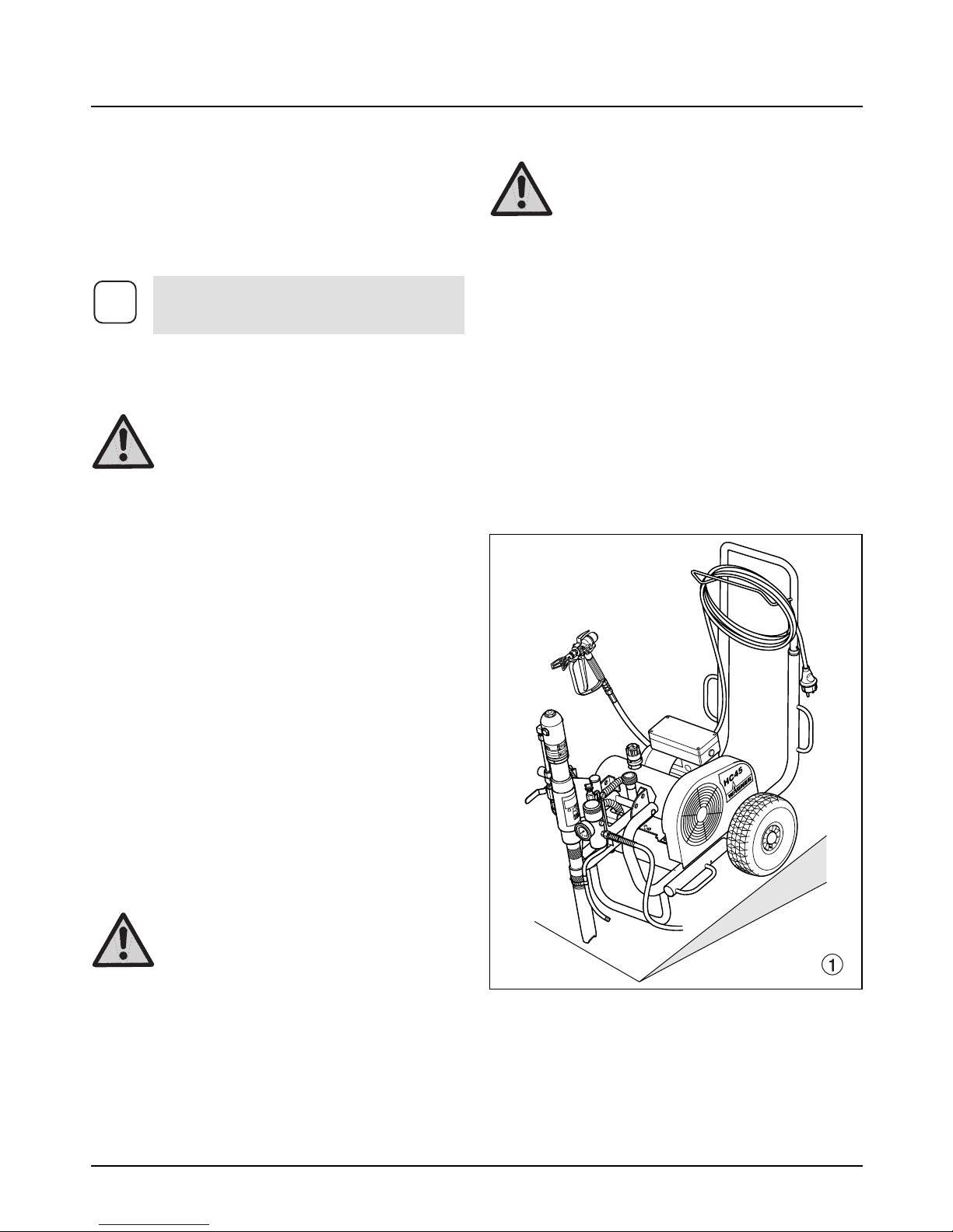
3.2 Funktion des Gerätes
Zum besseren Verständnis der Funktion kurz den technischen Aufbau.
WAGNER HC 35 E • 45 E • 55 E sind elektrisch angetriebene Hochdruckspritzgeräte.
Der Elektromotor (Abb. 2, Pos. 1) treibt über den Keilriemen unter der Riemenabdeckung (2) die Hydraulikpumpe (3) an. Hydrauliköl fließt zum Hydraulikmotor (4) und
bewegt dann den Kolben in der Materialförderpumpe (5)
auf und ab.
Bei den Geräten HC 45 E-SSP und HC 55 E-SSP bewegt
der Kolben in der Materialförderpumpe einen Schöpfkolben (6). Der Schöpfkolben fördert höchstviskose
Beschichtungsstoffe.
Durch die Aufwärtsbewegung des Kolbens öffnet das
Einlassventil selbständig. Bei der Abwärtsbewegung des
Kolbens öffnet das Auslassventil.
Der Beschichtungsstoff strömt unter hohem Druck durch
den Hochdruckschlauch zur Spritzpistole. Bei Austritt
aus der Düse zerstäubt der Beschichtungsstoff.
Das Druckregelventil (7) regelt die Fördermenge und den
Betriebsdruck des Beschichtungsstoffs.
HC 35 E • HC 45 E • HC 55 E 5
d
Gerätebeschreibung
7
1
34
2
56
Page 8

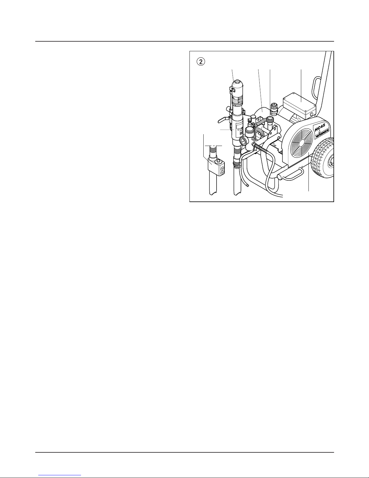
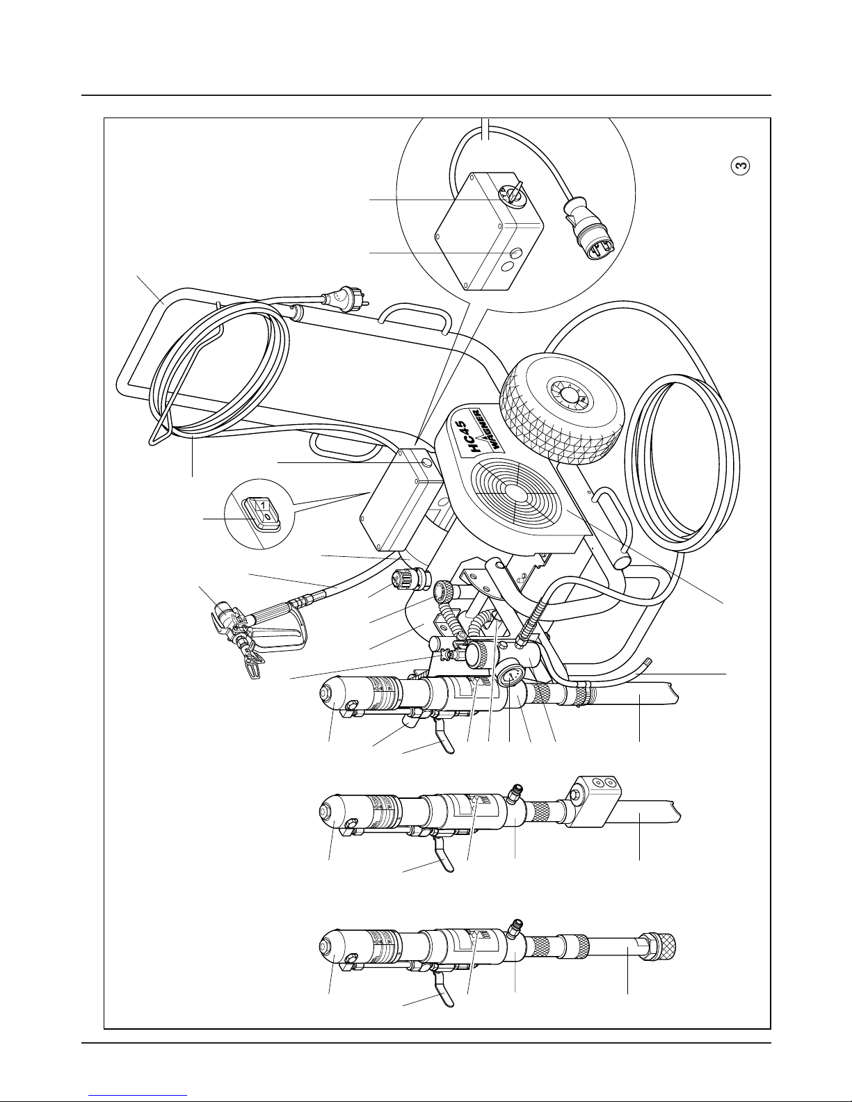
1 Spritzpistole
2 Hochdruckschlauch
3 Elektromotor
4 EIN/AUS-Schalter (230 V)
5 Kontrollleuchte zeigt
Betriebsbereitschaft an
HC 35 E, HC 45 E, HC 45 E-SSP
6 Geräteanschlussleitung
7 Deichsel ausziehbar
8 Kontrollleuchte zeigt
Betriebsbereitschaft an
HC 55 E, HC 55 E-SSP
9 EIN/AUS-Schalter (400 V)
HC 55 E, HC 55 E-SSP
10 Keilriemen unter der Riemenabdeckung
11 Rücklaufschlauch
12 Ansaugrohr
13 Hochdruckfilter
14 Materialförderpumpe
HC 45 E, HC 55 E
6 HC 35 E • HC 45 E • HC 55 E
d
Gerätebeschreibung
3.3 Legende zum Erklärungsbild HC-Geräte
15 Materialförderpumpe
HC 45 E-SSP, HC 55 E-SSP
16 Materialförderpumpe HC 35 E
17 Manometer
18 Arretierstift für die Schwenkeinrichtung
19 Einfüllöffnung für Trennöl
(Trennöl verhindert erhöhten Verschleiß
der Packungen)
20 Kugelhahn Hebelstellung waagrecht –
Hydraulikmotor ausgeschaltet
Hebelstellung senkrecht –
Hydraulikmotor eingeschaltet
21 Handgriff zum Schwenken
der Materialförderpumpe
22 Hydraulikmotor
23 Entlastungsventilknopf
Nach links drehen Zirkulation k
Nach rechts drehen Spritzen p
24 Hydraulikölpumpe
25 Druckregulierknopf
26 Ölmessstab
Page 9
HC 35 E • HC 45 E • HC 55 E 7
d
Gerätebeschreibung
13
20
2
3
4
9
12
17
18
23
24 25
10
14
6
7
1
11
26
21
19
22
20
12
15
19
22
20
12
16
19
22
8
5
3.4 Erklärungsbild HC-Geräte
Page 10

3.5 Technische Daten
HC 35 E HC 45 E
HC 45 E-SSP
HC 55 E HC 55 E-SSP
Spannung
230 V~, 50 Hz: ✲✲✲
400 V, 50 Hz, V3~: ✲✲
Absicherung
16 A: ✲✲✲✲✲
Geräteanschlussleitung
3 x 2,5 mm
2
– 6 m: ✲✲✲
5 x 2,5 mm2– 6 m: ✲✲
Aufnahmeleistung
3,1 kW: ✲✲✲
5,5 kW: ✲✲
max. Betriebsdruck
228 bar (22,8 MPa): ✲✲✲✲✲
max. Volumenstrom
5,5 l/min: ✲
6,6 l/min: ✲✲
10 l/min: ✲✲
Volumenstrom bei 120 bar (12 MPa) mit Wasser
4,8 l/min: ✲
5,2 l/min: ✲✲
10 l/min: ✲✲
max. Düsengröße mit einer Spritzpistole
0,043 inch (Zoll) – 1,10 mm: ✲
0,052 inch (Zoll) – 1,30 mm: ✲✲
0,056 inch (Zoll) – 1,42 mm: ✲✲
max. Temperatur des Beschichtungsstoffs
43° C: ✲✲✲✲✲
max. Viskosität
40.000 mPa·s: ✲
50.000 mPa·s: ✲✲
65.000 mPa·s: ✲✲
Filtereinsatz (Standardausführung)
5 Maschen: ✲
0 Maschen: ✲✲✲✲
Gewicht
83 kg: ✲✲
84,5 kg: ✲
100 kg: ✲
103 kg: ✲
Hydrauliköl-Füllmenge
4,7 l ESSO Nuto H 32: ✲✲✲✲✲
max. Reifendruck
2 bar (0,2 MPa): ✲✲✲✲✲
Spezial-Hochdruckschlauch
DN 10 mm, 15 m, Anschlussgewinde NPSM 3/8: ✲✲
DN 13 mm, 15 m, Anschlussgewinde NPSM 1/2: ✲✲✲
DN 19 mm, 15 m, Anschlussgewinde NPSM 3/4: ✲✲✲
Schlauchpeitsche
DN 10 mm, 2,5 m, Anschlussgewinde NPSM 3/8: ✲✲✲
Abmessungen L x H x B
1160 x 955 x 655 mm: ✲
1185 x 955 x 655 mm: ✲✲
1200 x 955 x 655 mm: ✲✲
max. Schalldruckpegel
77 dB (A)* ✲
80 dB (A)* ✲✲
88 dB (A)* ✲✲
* Messort: Abstand 1 m seitlich vom Gerät und 1,60 m über schallhartem Boden, 120 bar (12 MPa) Betriebsdruck.
8 HC 35 E • HC 45 E • HC 55 E
d
Gerätebeschreibung
Page 11
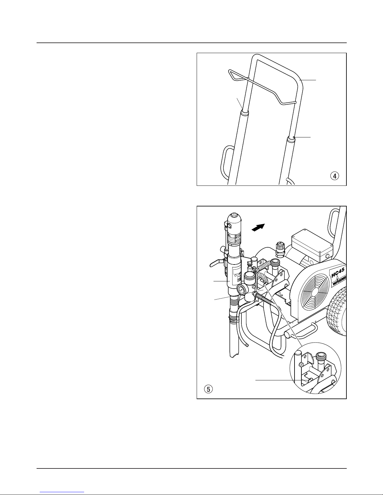
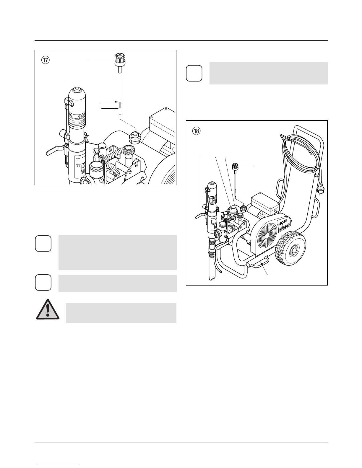
3.6 Transport
Gerät schieben.
Deichsel (Abb. 4, Pos. 1) bis zum Anschlag herausziehen. Deichsel einfahren – Druckknöpfe (2) an den Holmen eindrücken, dann Deichsel einfahren.
HC 35 E • HC 45 E • HC 55 E 9
d
Gerätebeschreibung
1
2
2
1
2
3
3.7 Transport im Fahrzeug
Arretierstift (Abb. 5, Pos. 1) ziehen in der Schwenkeinrichtung (2) für die Materialförderpumpe (3) und diese in
waagrechte Lage schwenken. Darauf achten, dass der
Arretierstift einrastet.
Hochdruckschlauch über die Aufhängung an der Deichsel aufrollen.
Gerät mit geeignetem Befestigungsmittel sichern.
Page 12
10 HC 35 E • HC 45 E • HC 55 E
d
Gerätebeschreibung Inbetriebnahme
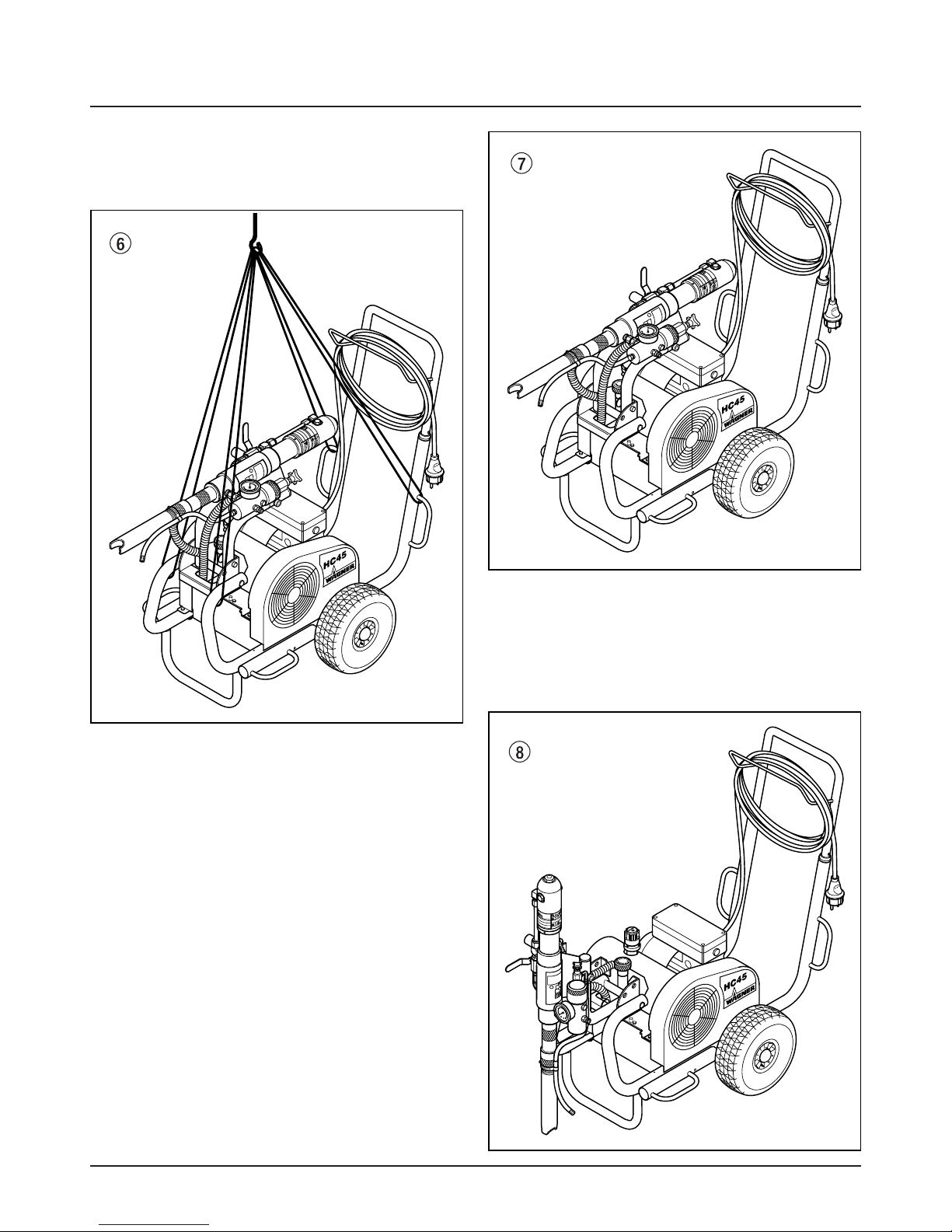
3.8 Krantransport
Anhängepunkte für die Bänder oder Seile, siehe Abbildung 6.
4. Inbetriebnahme
4.1 Schwenkeinrichtung der
Materialförderpumpe
1. Transportposition (Abb. 7)
Transport vom Gerät nur in horizontaler Position der
Materialförderpumpe vornehmen.
Materialförderpumpe in horizontale Position schwenken,
ermöglicht auch die Materialförderpumpe aus dem Beschichtungsstoff-Behälter zu entnehmen.
Darauf achten, dass der Arretierstift einrastet.
2.0 Arbeitsposition I (Abb. 8)
Materialförderpumpe in senkrechte Position schwenken,
ermöglicht die Materialförderpumpe in den Beschichtungsstoff-Behälter einzutauchen.
Page 13

2.1 Arbeitsposition II (Abb. 9)
Materialförderpumpe in schräge (45°) Position schwenken, bei Einsatz des Container Ansaugsystems
(Zubehör). In dieser Position ist Freiraum unter der
Materialförderpumpe.
HC 35 E • HC 45 E • HC 55 E 11
d
Inbetriebnahme
4.2 Position der Materialförderpumpe
ändern
1. Handgriff (Abb. 10, Pos. 1) mit der einen Hand greifen.
2. Mit der anderen Hand den Arretierstift (2) ziehen.
3. Materialförderpumpe je nach gewünschter Position
nach unten oder oben schwenken, bis der Arretierstift
(2) in der neuen Position einrastet.
Gefahr
Quetschgefahr für Finger und Fuß,
durch die sich bewegenden Teile der
Schwenkeinrichtung.
2
1
Page 14

2
4
1
1
5
6
3
4.4 Anschluss an das Stromnetz
Vor Anschluss an das Stromnetz darauf achten, dass die
Netzspannung übereinstimmt mit der Angabe auf dem
Leistungsschild am Gerät.
Sobald der Netzstecker angeschlossen ist, leuchtet die
grüne Kontrollleuchte.
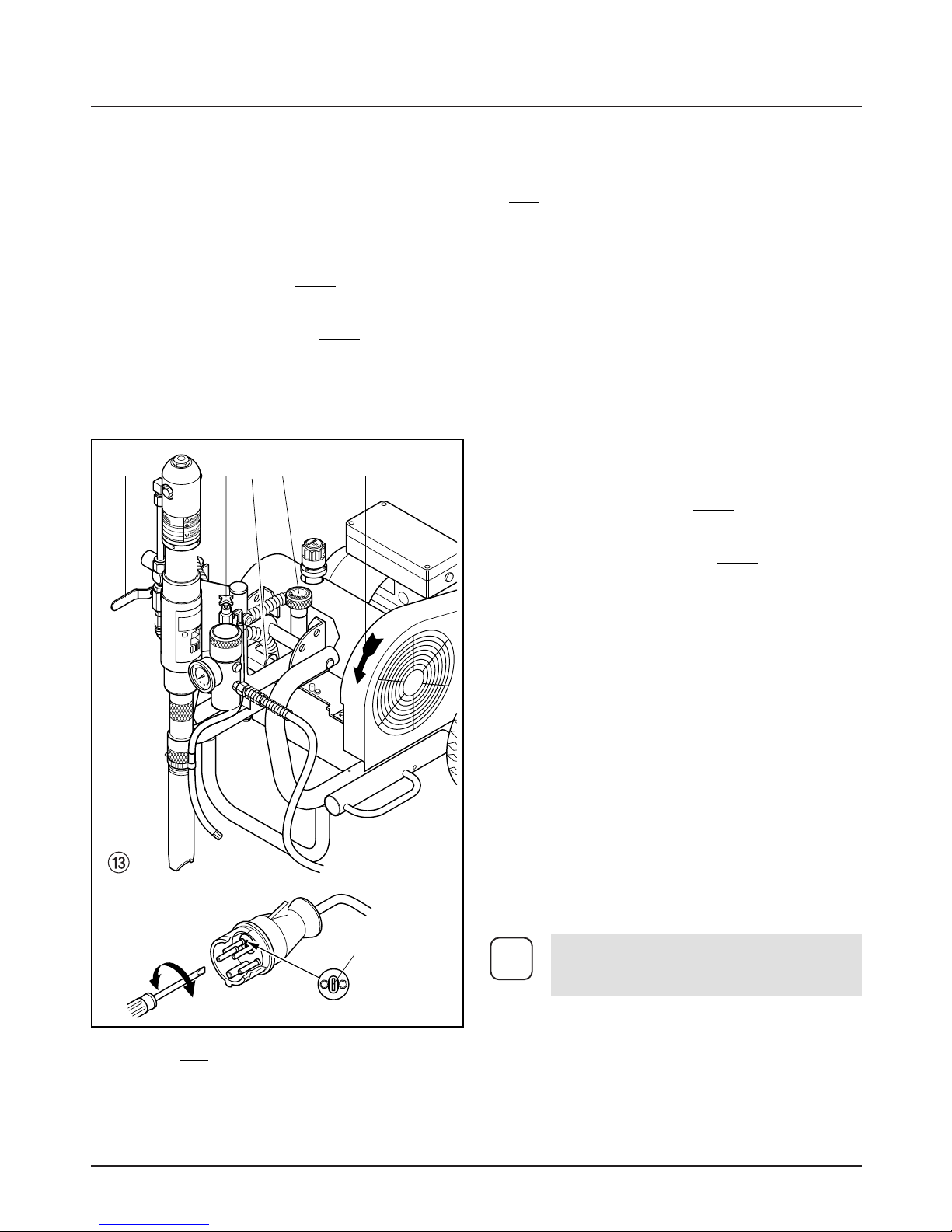
4.5 Bei Erstinbetriebnahme Reinigung
von Konservierungsmittel
1. Arretierstift (Abb. 13, Pos. 1) ziehen und Materialför-
derpumpe in einen Behälter mit geeignetem Reinigungsmittel einschwenken.
2. Druckregulierknopf (2) an der Hydraulikpumpe nach
links
drehen (Druckverringerung) bis zum Anschlag.
3. Entlastungsventilknopf (3) drei Umdrehungen nach
links
drehen (k Zirkulation).
4. Gerät einschalten.
HC 35 E • HC 45 E • HC 45 E-SSP
Schalter auf 1 (EIN) stellen.
HC 55 E • HC 55 E-SSP
Schalterknopf zuerst auf Y, dann auf (EIN) stellen.
Die Drehrichtung der Riemenscheibe muss dem Pfeil
(4) auf der Riemenabdeckung entsprechen. Falls die
Riemenscheibe entgegen der Pfeilrichtung läuft:
Achtung
12 HC 35 E • HC 45 E • HC 55 E
d
Inbetriebnahme
6.
7. Trennöl einfüllen (Abb. 12). Nur soviel einfüllen, dass
kein Trennöl in den Beschichtungsstoff-Behälter tropft.
Achtung
Trennöl verhindert erhöhten
Verschleiss der Packungen.
Der Anschluss muss über eine vorschriftsmäßig geerdete SchutzkontaktSteckdose erfolgen.
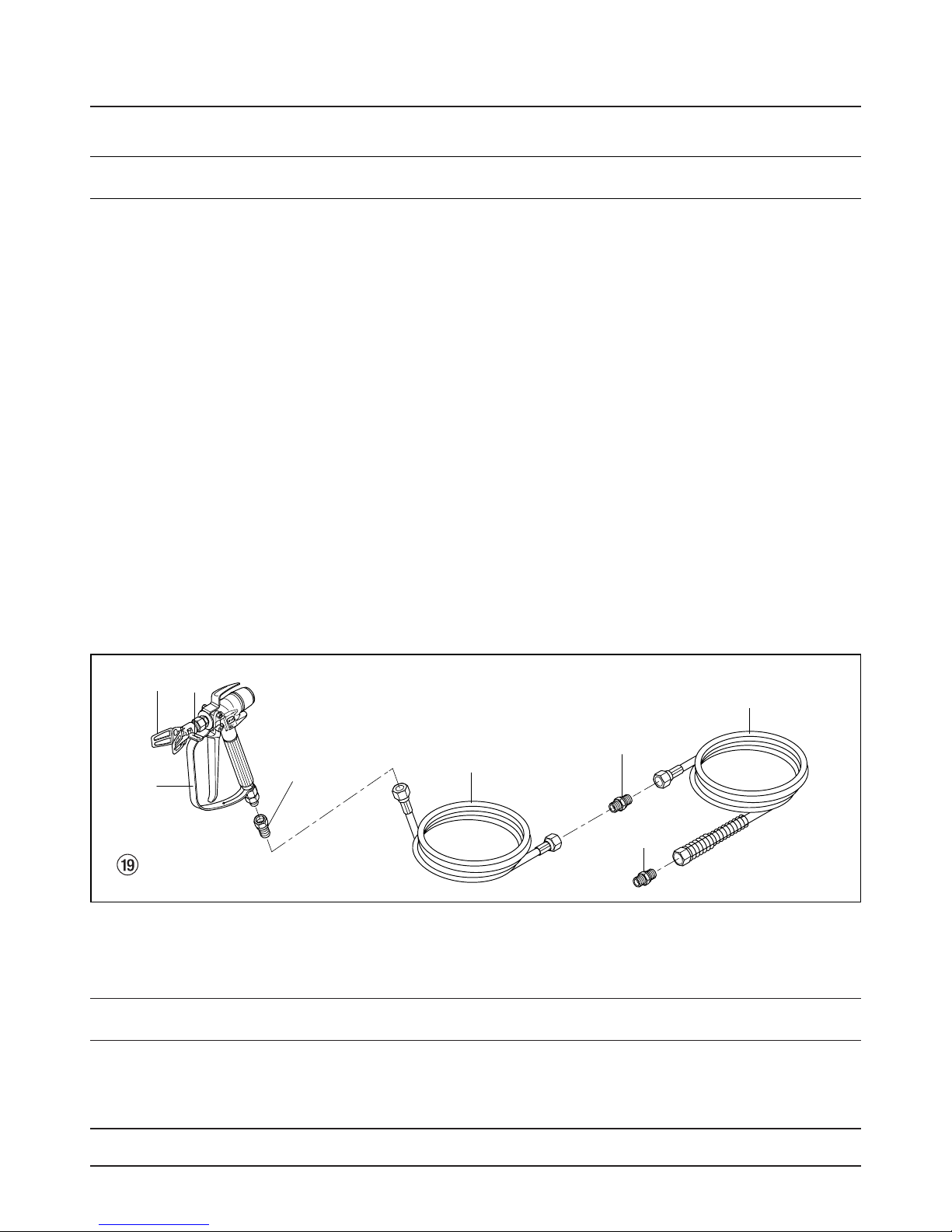
4.3 Hochdruckschlauch, Spritzpistole
und Trennöl
1. Hochdruckschlauch (Abb. 11, Pos. 1) am Schlauchanschluss (2) anschrauben.
2. HC 45 E-SSP • HC 55 E und HC 55 E-SSP Doppelstutzen (3) in den Hochdruckschlauch einschrauben.
Schlauchpeitsche (4) anschrauben.
3. Übergangsstutzen (5) an die Spritzpistole (6) schrauben.
4. Spritzspistole mit ausgewählter Düse je nach Ausführung am Hochdruckschlauch oder an der
Schlauchpeitsche (4) anschrauben.
5. Überwurfmuttern am Hochdruckschlauch und je nach
Ausführung auch an der Schlauchpeitsche fest anziehen, damit kein Beschichtungsstoff austritt.
Page 15
HC 35 E • HC 45 E • HC 55 E 13
d
Inbetriebnahme Spritztechnik
216 3 4
5
HC55E
HC55E-SSP
Gerät ausschalten O (AUS). Netzstecker ausstecken
und mit einem Schraubendreher den Polwender (5) im
Netzstecker um 180 Grad drehen. Netzstecker wieder
einstecken.
5. Kugelhahn (6) an der Materialförderpumpe – Hebel
senkrecht stellen – Hydraulikmotor einschalten.
Hydrauliköl fließt zum Hydraulikmotor der Materialförderpumpe.
6. Druckregulierknopf (2) nach r
echts drehen (Druckerhöhung), bis Reinigungsmittel aus dem Rücklaufschlauch austritt.
7. Entlastungsventilknopf (3) nach r
echts drehen
(p Spritzen).
8. Abzugsbügel der Spritzpistole ziehen.
9. Reinigungsmittel aus dem Gerät in einen offenen
Sammelbehälter spritzen.
2. Druckregulierknopf (2) an der Hydraulikpumpe nach
links drehen (Druckverringerung) bis zum Anschlag.
3. Entlastungsventilknopf (3) drei Umdrehungen nach
links
drehen (k Zirkulation).
4. Gerät einschalten.
HC 35 E • HC 45 E • HC 45 E-SSP
Schalter auf 1 (EIN) stellen.
HC 55 E • HC 55 E-SSP
Schalterknopf zuerst auf Y, dann auf (EIN) stellen.
Die Drehrichtung der Riemenscheibe muss dem Pfeil
(4) auf der Riemenabdeckung entsprechen. Falls die
Riemenscheibe entgegen der Pfeilrichtung läuft:
Gerät ausschalten O (AUS). Netzstecker ausstecken
und mit einem Schraubendreher den Polwender (5) im
Netzstecker um 180 Grad drehen. Netzstecker wieder
einstecken.
5. Kugelhahn (6) an der Materialförderpumpe – Hebel
senkrecht stellen – Hydraulikmotor einschalten.
Hydrauliköl fließt zum Hydraulikmotor der Materialförderpumpe.
6. Druckregulierknopf (2) nach r
echts drehen (Druckerhöhung), bis Beschichtungsstoff aus dem Rücklaufschlauch austritt.
7. Entlastungsventilknopf (3) nach r
echts drehen
(p Spritzen).
8. Abzugsbügel der Spritzpistole ziehen, dann den gewünschten Betriebsdruck mit dem Druckregulierknopf
(2) einstellen.
9. Das Gerät ist spritzbereit.
5. Spritztechnik
Während des Spritzvorganges die Spritzpistole gleichmäßig führen. Bei Nichteinhaltung tritt ein unregelmäßiges Spritzbild auf. Die Spritzbewegung mit dem Arm
ausführen und nicht mit dem Handgelenk. Ein paralleler
Abstand von ca. 30 cm zwischen Spritzpistole und
Spritzobjekt einhalten. Die seitliche Abgrenzung des
Spritzstrahles soll nicht zu scharf sein. Der Spritzrand
sollte allmählich auflockern, damit beim nächsten Durchgang leicht überlappt werden kann. Spritzpistole immer
parallel und im Winkel von 90° zur Spritzfläche führen, so
entsteht am wenigsten Farbnebel.
4.6 Gerät mit
Beschichtungsstoff
in Betrieb nehmen
1. Arretierstift (Abb. 13, Pos. 1) ziehen und Materialförderpumpe in den Beschichtungsstoff-Behälter einschwenken.
Beim Auftreten sehr scharfer Randzonen und
Streifen im Spritzstrahl – Betriebsdruck erhöhen oder Beschichtungsstoff verdünnen.
i
Page 16
7. Arbeitsunterbrechung
1. Kugelhahn an der Materialförderpumpe schließen –
Hebelstellung waagrecht.
Hydrauliköl-Durchfluss zum Hydraulikmotor der Ma-
terialförderpumpe ist unterbrochen.
2. Entlastungsventilknopf drei Umdrehungen nach links
drehen (k Zirkulation).
3. Gerät ausschalten O (AUS).
4. Abzugsbügel der Spritzpistole ziehen, um Hoch-
druckschlauch und Spritzpistole vom Druck zu entlasten.
5. Spritzpistole sichern, siehe Betriebsanleitung der
Spritzpistole.
6. Falls eine Standarddüse gereinigt werden soll, siehe
Seite 27, Punkt 13.2.
Ist eine andere Düsenausführung montiert, dann
nach entsprechender Betriebsanleitung vorgehen.
7. Ansaugrohr im Beschichtungsstoff eingetaucht las-
sen oder dieses in ein entsprechendes Reinigungsmittel eintauchen.
8. Gerätereinigung
(Außerbetriebnahme)
Sauberkeit ist die sicherste Gewährleistung für einen
störungsfreien Betrieb. Nach Beendigung der Spritzarbeiten Gerät reinigen. Auf keinen Fall dürfen Beschichtungsstoffe im Gerät antrocknen und sich festsetzen.
6. Handhabung des Hochdruck-
schlauches
Scharfes Biegen oder Knicken des Hochdruckschlauches vermeiden, kleinster Biegeradius etwa 20 cm.
Hochdruckschlauch nicht überfahren, sowie vor scharfen
Gegenständen und Kanten schützen.
6.1 Hochdruckschlauch
Das Gerät ist mit einem speziell für Kolbenpumpen
geeigneten Hochdruckschlauch ausgerüstet.
Gefahr
14 HC 35 E • HC 45 E • HC 55 E
d
Arbeitsunterbrechung Gerätereinigung (Außerbetriebnahme)
Achtung
Beim Einsatz von schnelltrocknenden
– oder Zweikomponenten-Beschichtungsstoff, Gerät unbedingt innerhalb
der Verarbeitungszeit mit geeignetem
Reinigungsmittel durchspülen.
Das zur Reinigung verwendete Reinigungsmittel (nur mit
einem Flammpunkt über 21° C) muss dem Beschichtungsstoffe entsprechen.
• Spritzpistole sichern, siehe Betriebsanleitung der
Spritzpistole.
Düse reinigen und demontieren.
Standarddüse siehe Seite 27, Punkt 13.2.
Ist eine andere Düsenausführung montiert, dann nach
entsprechender Betriebsanleitung vorgehen.
1. Arretierstift ziehen und Materialförderpumpe aus
dem Beschichtungsstoff herausschwenken.
2. Abzugsbügel an der Spritzpistole ziehen, um restli-
chen Beschichtungsstoff aus dem Ansaugrohr,
Hochdruckschlauch und der Spritzpistole in einen
offenen Behälter zu pumpen.
3. Arretierstift ziehen und Materialförderpumpe in
einen Behälter mit geeignetem Reinigungsmittel
einschwenken.
4. Entlastungsventilknopf drei Umdrehungen nach
links
drehen (k Zirkulation).
5. Geeignetes Reinigungsmittel einige Minuten im
Kreislauf pumpen.
6. Entlastungsventilknopf nach r
echts drehen
(p Spritzen).
7. Restliches Reinigungsmittel in einen offenen
Behälter pumpen, bis das Gerät leer ist.
8. Entlastungsventilknopf drei Umdrehungen nach
links
drehen (k Zirkulation).
9. Kugelhahn an der Materialförderpumpe schließen –
Hebelstellung waagrecht.
10. Gerät ausschalten O (AUS).
8.1 Gerätereinigung von außen
Gerät außen mit einem in geeignetem Reinigungsmittel
getränkten Tuch abwischen.
Bei lösemittelhaltigen Beschichtungsstoffen muss der Behälter geerdet werden.
Achtung
Vorsicht! Nicht in Behälter mit kleiner
Öffnung (Spundloch) pumpen oder
spritzen!
Siehe Sicherheitsvorschriften.
Gefahr
Zuerst Netzstecker aus der Steckdose
ziehen.
Gefahr
Kurzschlussgefahr durch eindringendes Wasser!
Gerät niemals mit Hochdruck- oder
Dampfhochdruckreiniger abspritzen.
Gefahr
Verletzungsgefahr durch undichten Hochdruckschlauch. Beschädigten Hochdruckschlauch sofort ersetzen.
Niemals defekten Hochdruckschlauch
selbst reparieren!
Aus Gründen der Funktion, Sicherheit und
Lebensdauer nur WAGNER Original-Hochdruckschläuche verwenden.
i
Page 17
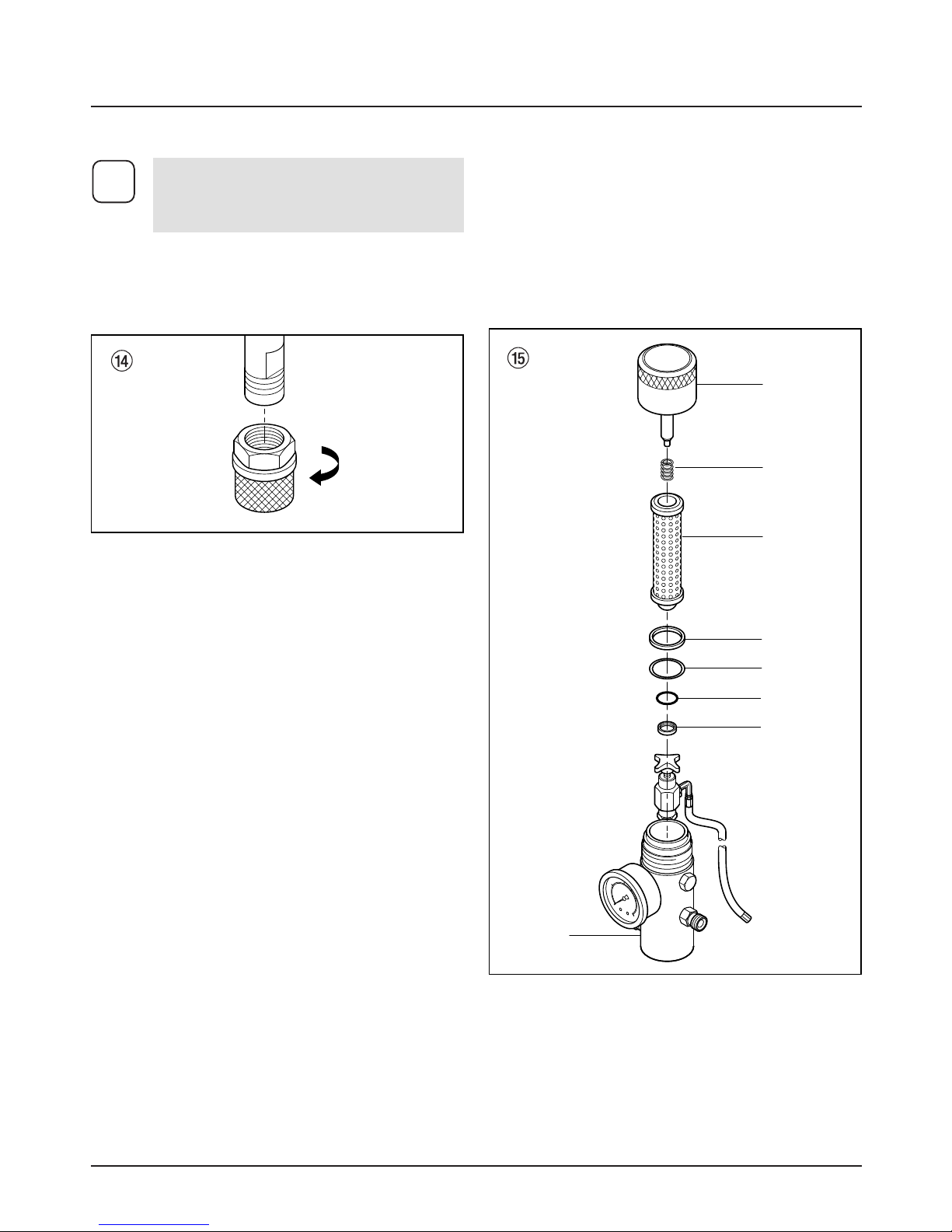
8.3 Hochdruckfilter reinigen
Filterpatrone regelmäßig reinigen.
Ein verschmutzter oder verstopfter Hochdruckfilter verur-
sacht ein schlechtes Spritzbild oder eine verstopfte Düse.
Demontage
1. Kugelhahn an der Materialförderpumpe schließen –
Hebelstellung waagrecht.
Hydrauliköl-Durchfluss zum Hydraulikmotor der Materialförderpumpe ist unterbrochen.
2. Entlastungsventilknopf drei Umdrehungen nach
links drehen (k Zirkulation).
3. Gerät ausschalten O (AUS).
4. Gehäusedeckel (Abb. 15, Pos. 1) abschrauben.
5. Filterpatrone (3) aus dem Gehäuse (8) herausziehen.
6. Mit entsprechendem Reinigungsmittel Druckfeder
(2) und Filterpatrone (3) mit Kugel reinigen, Gehäuse
(8) und Gehäusedeckel (1) innen reinigen.
7. Kugel in der Filterpatrone (3) auf Verschleißspuren
prüfen, wenn notwendig Filterpatrone austauschen.
8. Kugel in der Filterpatrone (3) ist stark verschlissen,
dann O-Ring (6) und Ventilsitz (7) ausbauen. Eventuell verschlissenen Ventilsitz austauschen.
9. O-Ring (6) nach Ausbau immer austauschen.
10. Druckfeder (2) vom Gehäusedeckel (1) abziehen.
Länge der Druckfeder messen, falls weniger als 19
mm, dann Druckfeder austauschen.
Montage
1. Ventilsitz (7) mit der Kugelsitzfläche nach oben in
das Gehäuse (8) einlegen.
HC 35 E • HC 45 E • HC 55 E 15
d
Gerätereinigung (Außerbetriebnahme)
Ein sauberer Ansaugfilter gewährleistet stets
maximale Fördermenge, konstanten Spritzdruck und einwandfreies Funktionieren des
Gerätes.
i
8.2 Ansaugfilter bei HC 35 E
– Filter (Abb. 14) vom Ansaugrohr abschrauben.
– Filter reinigen oder austauschen.
Reinigung mit einem harten Pinsel und
entsprechendem Reinigungsmittel durchführen.
2. O-Ring (6) in das Gehäuse (8) einlegen.
3. Filterpatrone (3) einsetzen.
4. Dünne Dichtung (5) auf den Gewindeabsatz am
Gehäuse (8) auflegen.
5. Dicke Dichtung (4) auf die dünne Dichtung (5) legen.
6. Druckfeder (2) auf den Stift im Gehäusedeckel (1)
aufschieben.
7. Gehäusedeckel (1) aufschrauben und von Hand anziehen.
1
2
3
4
5
6
7
8
8.4 Reinigung der Airless-Spritzpistole
– Airless-Spritzpistole bei niedrigem Betriebsdruck
mit geeignetem Reinigungsmittel durchspülen.
– Düse gründlich mit geeignetem Reinigungsmittel
reinigen, so dass keine Beschichtungsstoffreste
zurückbleiben.
– Airless-Spritzpistole außen gründlich reinigen.
Page 18
Hydraulikmotor bleibt
in der unteren Stellung
stehen
Auslassventilsitz in der Materialförderpumpe lose.
Umschaltventil im Hydraulikmotor sitzt fest oder obere/untere Sechskantmutter
an der Ventilstange hat sich
gelöst.
Kugelhahn an der Materialförderpumpe – Hebelstellung senkrecht. Verschlussschraube am Hydraulikmotor oben abschrauben. Umschaltventil im Hydraulikmotor nach unten drücken. Verschlussschraube wieder montieren. Gerät starten. Die Kolbenstange bewegt sich nach oben und bleibt wieder in der unteren
Stellung stehen. Dann ist die Ursache, der lose Auslassventilsitz.
Von Wagner-Service beheben lassen.
Von Wagner-Service beheben lassen.
9.2 Hydraulikmotor
Art der Störung Mögliche Ursache Maßnahme zur Behebung der Störung
16 HC 35 E • HC 45 E • HC 55 E
d
Gerätereinigung (Außerbetriebnahme) Hilfe bei Störungen
9. Hilfe bei Störungen
9.1 Elektromotor
Gerät läuft nicht an
HC 55 E, HC 55 E-SSP
(400 V)
Kolbenstange in der Materialförderpumpe läuft nicht
auf und ab.
Kontrollleuchte zeigt keine
Betriebsbereitschaft an.
Keine Spannung vorhanden
Bei Überbelastung
schaltet sich das Gerät
automatisch ab.
Das Gerät schaltet nicht
selbständig wieder ein.
Drehrichtung des Elektromotors falsch.
Spannungsversorgung prüfen
Nach 2 – 3 Minuten, Gerät wieder einschalten.
Polwender im Netzstecker um 180 Grad drehen.
Art der Störung Mögliche Ursache Maßnahme zur Behebung der Störung
Made in Germany
m
a
x
.
3
9
0
0
p
s
i
2
7
0
b
a
r
G
1
2
1
2
3
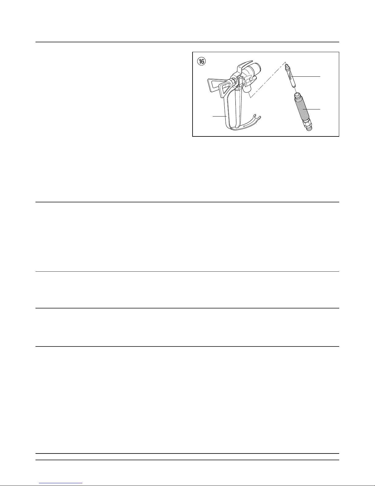
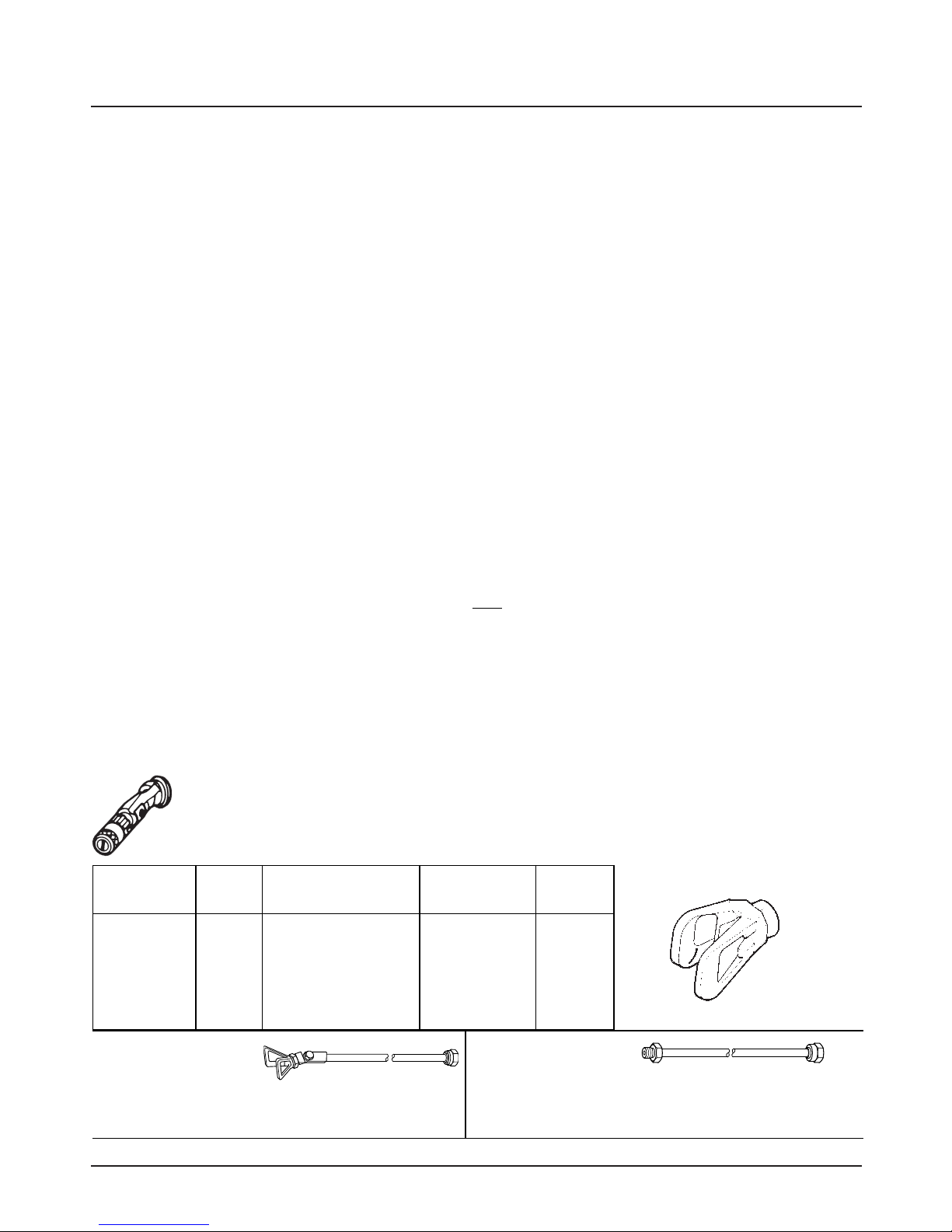
Einsteckfilter in der Airless-Spritzpistole
Demontage (Abb. 16)
1. Schutzbügel (1) kräftig nach vorne ziehen.
2. Griff (2) aus dem Pistolengehäuse schrauben. Einsteckfilter (3) herausziehen.
3. Einsteckfilter verstopft oder defekt – ersetzen.
Montage
1. Einsteckfilter (3) mit dem längeren Konus in das Pistolengehäuse stecken.
2. Griff (2) in das Pistolengehäuse einschrauben und
anziehen.
3. Schutzbügel (1) einrasten
Page 19

HC 35 E • HC 45 E • HC 55 E 17
d
Hilfe bei Störungen
Hydraulikmotor bleibt
in der unteren Stellung
stehen
Niedriger Druck.
Kolbenstange bewegt sich
normal im Abwärtshub,
der Aufwärtshub ist aber
träge. Hydraulikmotor ist
außen sehr heiß.
Niedriger Druck.
Beim Aufwärts- und Abwärtshub wird der Hydraulikmotor außen sehr heiß.
Umschaltventil sitzt fest.
Druckfeder auf der Ventilstange ist gebrochen.
Druckfederanschlag auf der
Ventilstange ist gebrochen.
Luft im Hydraulikmotor.
Luft in der Materialförderpumpe.
Defekte Kolbendichtung im
Hydraulikmotor.
Kolbenstange gebrochen.
Mittlerer O-Ring am Umschaltventil defekt.
Packungen in der Materialförderpumpe verschlissen.
Von Wagner-Service beheben lassen.
Von Wagner-Service beheben lassen.
Von Wagner-Service beheben lassen.
Druckregulierknopf zurückdrehen.
Entlüften bei niedrigem Druck während 5-10 Minuten
Dauerlauf. Materialförderpumpe nicht trocken laufen
lassen.
Kontrolle auf Undichtigkeiten:
• Lose Anschlüsse am Hydrauliköltank.
• Lose Anschlüsse an der Hydraulikölpumpe
• Lose Hydraulikölschlauchanschlüsse
• Zu niederer Ölstand im Hydrauliktank
Kugelhahn an der Materialförderpumpe – Hebelstellung senkrecht. Verschlussschraube am Hydraulikmotor oben abschrauben. Umschaltventil im Hydraulikmotor nach unten drücken. Verschlussschraube wieder montieren. Gerät starten. Vermeiden, dass die Materialförderpumpe Luft ansaugt.
Von Wagner-Service beheben lassen.
Von Wagner-Service beheben lassen.
Von Wagner-Service beheben lassen.
Austauschen
Art der Störung Mögliche Ursache Maßnahme zur Behebung der Störung
9.3 Materialförderpumpe
Art der Störung Mögliche Ursache Maßnahme zur Behebung der Störung
BeschichtungsstoffFörderung nur im
Aufwärtshub oder Kolbenstange bewegt sich
langsam aufwärts und
schnell abwärts.
BeschichtungsstoffFörderung nur im
Abwärtshub oder Kolbenstange bewegt sich
langsam abwärts und
schnell aufwärts
Einlassventil ist undicht
durch Verunreinigung oder
Verschleiß.
Beschichtungsstoff hat zu
hohe Viskosität, um angesaugt zu werden.
Auslassventil undicht.
Untere Packung
verschlissen.
Einlassventilgehäuse reinigen und kontrollieren. Kugel
einsetzen und Wasser einfüllen, wenn undicht Kugel
austauschen.
Entsprechend Herstellerangaben verdünnen.
Auslassventilsitz ausbauen und kontrollieren.
Kugel einsetzen und Wasser einfüllen, wenn undicht
Kugel austauschen.
Austauschen
Page 20

10.2 Ölstandkontrolle im Hydrauliköltank
1. Ölmessstab (Abb. 17, Pos. 1) nach links
drehen und Ölmessstab herausziehen.
2. Der Ölstand soll zwischen der Markierung
(siehe Pfeile) am Ölmessstab sichtbar sein.
3. Falls notwendig Öl nachfüllen, Ölsorte siehe
unter Ölwechsel, Kapitel 10.3.
18 HC 35 E • HC 45 E • HC 55 E
d
10. Wartung
10.1 Allgemeine Wartung
Die Wartung des Gerätes soll einmal jährlich
durch den Wagner-Service durchgeführt werden.
1. Hochdruckschläuche, Geräteanschlussleitung
und Stecker auf Beschädigung prüfen.
2. Einlass- und Auslassventil auf Verschleiß
prüfen.
3. Ölstand im Hydrauliköltank prüfen.
4. Eventuell Ölwechsel durchführen.
Ölstand täglich kontrollieren
i
Gefahr
Gerät ausschalten A (AUS).
Netzstecker aus der Steckdose ziehen.
Hilfe bei Störungen Wartung
Kolbenstange bewegt sich
schnell auf und ab.
Kolbenstange bewegt
sich langsam auf und ab
bei geschlossener Spritzpistole.
Nicht genügend Druck an
der Spritzpistole.
Kolbenstange stottert im
Aufwärts- oder Abwärtshub.
Ansaugrohr ragt über den
Flüssigkeitsspiegel hinaus
und saugt Luft an.
Beschichtungsstoff hat zu
hohe Viskosität, um angesaugt zu werden.
Kugel im Einlassventilgehäuse klebt fest.
Lose Verbindungen
Entlastungsventil ist nicht
ganz geschlossen
Entlastungsventil
verschlissen
Untere Packung
verschlissen.
Kugel im Einlassventilgehäuse und Kugel im
Auslassventilsitz dichtet
nicht ab.
Düse verschlissen
Filterpatrone im Hochdruckfilter verstopft.
Hochdruckschlauch zu lang
Lösungsmittel hat obere
Packung aufquellen lassen.
Beschichtungsstoff nachfüllen
Beschichtungsstoff entsprechend Herstellerangaben
verdünnen.
Materialförderpumpe entlüften, Entlastungsventilknopf
nach links drehen (k Zirkulation).
Einlassventilgehäuse ausbauen, Kugel und Ventilsitz
reinigen.
Alle Verbindungen zwischen Materialförderpumpe und
Spritzpistole kontrollieren.
Entlastungsventilknopf nach rechts drehen
(p Spritzen).
Austauschen
Helfen oben beschriebene Maßnahmen nicht, dann
untere Packung austauschen.
Einlassventilgehäuse und Auslassventilsitz ausbauen.
Kugeln und Ventilsitze reinigen.
Austauschen
Filterpatrone reinigen oder austauschen.
Länge reduzieren.
Obere Packung austauschen.
Art der Störung Mögliche Ursache Maßnahme zur Behebung der Störung
Page 21
7. 4,7 Liter Hydrauliköl ESSO NUTO H 32 einfüllen.
8. Gerät mindestens 5 Minuten bei niedrigem Druck
laufen lassen, zur automatischen Entlüftung des
Hydrauliksystems.
HC 35 E • HC 45 E • HC 55 E 19
d
Wartung
1
min:
max:
1. Kugelhahn (Abb. 18, Pos. 1) an der Materialförderpumpe – Hebelstellung senkrecht.
2. Schrauben an der Abdeckung (2) der Hydraulikölpumpe abschrauben und Abdeckung abnehmen.
3. Ölmessstab (3) nach links drehen und herausziehen.
4. Ölfilter (4) mit Bandschlüssel abschrauben und austauschen.
5. Verschlussschraube (5) unter dem Hydrauliköltank
abschrauben. Altöl ablassen.
6. Verschlussschraube wieder einschrauben.
Umweltgefährdung
Altöl nicht in das Kanalnetz oder Erdreich ab-
lassen. Grundwasserverschmutzung ist strafbar. Altöl wird beim Kauf von Hydrauliköl
zurückgenommen.
i
Gefahr
Gerät ausschalten A (AUS).
Netzstecker aus der Steckdose ziehen.
10.3 Öl- und Ölfilterwechsel bei der
Hydraulikölpumpe
Öl- und Ölfilterwechsel alle 12 Monate durchführen.
Ölwechsel im betriebswarmen Zustand
des Gerätes vornehmen.
i
Beim Ölfüllvorgang kann Luft in das Hydrauliksystem gelangen. Deshalb ist ein Entlüften
des Systems notwendig.
i
1
3
4 2
5
10.4 Hochdruckschlauch
Hochdruckschlauch optisch auf eventuell vorhandene
Einschnitte oder Ausbeulungen, insbesondere am Übergang in die Armatur, prüfen. Überwurfmuttern müssen
sich frei drehen lassen.
Page 22
20 HC 35 E • HC 45 E • HC 55 E
d
12. Zubehör und Ersatzteile
12.1 Zubehör für HC-Geräte (Zubehörbild, siehe Seite 120)
HC 35 E HC 45 E HC 45 E-SSP HC 55 E HC 55 E-SSP
Pos. Best. Nr. Best. Nr. Best. Nr. Best. Nr. Best. Nr. Benennung
1 0096 004 0096 004 0096 004 0096 004 0096 004 Auslegerpistole 30 cm
0096 019 0096 019 0096 019 0096 019 0096 019 Auslegerpistole 100 cm
0096 005 0096 005 0096 005 0096 005 0096 005 Auslegerpistole 150 cm
0096 006 0096 006 0096 006 0096 006 0096 006 Auslegerpistole 270 cm
11. Standardausrüstung HC-Geräte
Standardausrüstung Zubehör und Ersatzteile
HC 35 E HC 45 E HC 45 E-SSP HC 55 E HC 55 E-SSP
Pos. Best. Nr. Best. Nr. Best. Nr. Best. Nr. Best. Nr. Benennung
1 0335 002 0335 002 –––––––– –––––––– –––––––– Spritzpistole G 12
–––––––– –––––––– 0347 002 0347 002 0347 002 Spritzpistole G 15
2 1088 001 1088 001 1088 001 1088 001 1088 001 Wagner Tip Halter
3 1088 427 1088 427 –––––––– –––––––– –––––––– Wagner Tip Düse 0,69 mm / 027 – 40°
1088 433 1088 433 1088 433 Wagner Tip Düse 0,83 mm / 033 – 40°
–––––––– –––––––– 1088 243 –––––––– 1088 243 Wagner Tip Düse 1,10 mm / 043 – 20°
4 0097 204 0097 204 0097 204 0097 204 0097 204 Übergangsstutzen
M 16 x 1,5 – NPSM 3/8
–––––––– –––––––– 0349 256 0349 256 0349 256 Übergangsstutzen
M 16 x 1,5 – NPSM 1/2
5 –––––––– –––––––– 9984 567 9984 567 9984 567 Schlauchpeitsche
DN 10 mm, 2,5 m, NPSM 3/8
6 –––––––– –––––––– 3203 026 3203 026 3203 026 Doppelstutzen 3/8 – 1/2
–––––––– –––––––– 9985 783 9985 783 9985 783 Doppelstutzen 3/8 – 3/4
–––––––– –––––––– 9985 782 9985 782 9985 782 Doppelstutzen 1/2 – 3/4
7 9984 506 9984 506 –––––––– –––––––– –––––––– Spezial Hochdruckschlauch
DN 10 mm, 15 m, NPSM 3/8
–––––––– –––––––– 9984 568 9984 568 9984 568 Spezial Hochdruckschlauch
DN 13 mm, 15 m, NPSM 1/2
–––––––– –––––––– 9984 571 9984 571 9984 571 Spezial-Hochdruckschlauch
DN 19 mm, 15 m, NPSM 3/4
8 –––––––– –––––––– 9985 783 9985 783 9985 783 Doppelstutzen 3/8 – 3/4
Anschluss am Hochdruckfilter
6
3
4
2
1
5
8
7
Page 23

HC 35 E • HC 45 E • HC 55 E 21
d
Zubehör und Ersatzteile
HC 35 E HC 45 E HC 45 E-SSP HC 55 E HC 55 E-SSP
Pos. Best. Nr. Best. Nr. Best. Nr. Best. Nr. Best. Nr. Benennung
2 –––––––– –––––––– –––––––– –––––––– –––––––– Hochdruckschläuche und
Übergangsstutzen, siehe unter
11. Standardausrüstung
3 0256 343 0256 343 –––––––– –––––––– –––––––– Doppelstutzen NPSM 3/8
(für Schlauchverlängerung)
–––––––– –––––––– 3202 901 3202 901 3202 901 Doppelstutzen 1/2
(für Schlauchverlängerung)
–––––––– –––––––– 9985 781 9985 781 9985 781 Doppelstutzen 3/4
(für Schlauchverlängerung)
4 0268 905 0268 905 0268 905 0268 905 0268 905 Strukturdüsensatz 4, 6, 8, 10 mm
5 0258 202 0258 202 0258 202 0258 202 0258 202 Spritzkopf zur Verarbeitung von
Airless-Spachtelmassen
(Sprenkelstruktur) mit Luftunterstützung
0258 720 0258 720 0258 720 0258 720 0258 720 Sprenkelstruktur-Set:
Spritzkopf, Strukturdüsensatz, Düsenreinigungsnadel und Luftschlauch
DN 9 mm, 15 m mit Schnellkupplung
(ohne Abbildung)
6 0345 010 0345 010 0345 010 0345 010 0345 010 Inline Roller IR-100
7 –––––––– 0349 907 0349 907 0349 907 0349 907 Container Ansaugsystem,
Schlauchdurchmesser 50 mm
–––––––– –––––––– 0349 908 –––––––– 0349 908 Container Ansaugsystem,
Schlauchdurchmesser 75 mm
für Airless-Spritzspachtel
8 –––––––– 0258 712 –––––––– 0258 712 –––––––– Dispersions-System
9 –––––––– 0258 715 –––––––– 0258 715 –––––––– Spachtel-System
10 –––––––– –––––––– 0349 910 –––––––– 0349 910 Behälter – Spacspray (Spachtel)
12.2 Ersatzteilliste Materialförderpumpe HC 35 E
(Ersatzteilbild, siehe Seite 121)
Pos. Best. Nr. Benennung
1 0349 473 Abdeckung (2)
2 0349 472 Schraube (2)
3 0349 406*(**) Spiralring
4 0349 506 Verbindungsstift
5 0349 612 Adapter
6 0349 238*(**) Packung komplett (2)
7 0349 498 Konusfeder
8 0349 507* Kolbenstange
9 0349 493 Federteller
10 0349 505*(**) Buchse
11 0349 504 Druckfeder
13 0349 519*(**) Kugel
Pos. Best. Nr. Benennung
14 0349 500 Auslassventilsitz
15 0349 503*(**) O-Ring (2)
16 0349 508* Zylinder
17 0349 502*(**) O-Ring
18 0349 501 Kugelführung
19 0349 509*(**) Kugel
21 0349 518 Einlassventilgehäuse
22 0349 517 Ansaugrohr
23 0349 602 Filter, 10 Maschen
0349 716* Service-Set Materialförderpumpe
0349 717** Service-Set Ventile und Packungen
9992 504 Trennöl 250 ml (Mesamoll)
Page 24

22 HC 35 E • HC 45 E • HC 55 E
d
12.3 Ersatzteilliste Materialförderpumpe
HC 45 E • HC 45 E-SSP • HC 55 E • HC 55 E-SSP
(Ersatzteilbild, siehe Seite 121)
HC 45 E
HC 45 E-SSP
HC 55 E HC 55 E-SSP
Pos. Best. Nr. Best. Nr. Best. Nr. Best. Nr. Benennung
1 0349 473 0349 473 0349 473 0349 473 Abdeckung (2)
2 0349 472 0349 472 0349 472 0349 472 Schraube (2)
3 0349 406*(**) 0349 406*(**) 0349 406*(**) 0349 406*(**) Spiralring
4 0349 407 0349 407 0349 407 0349 407 Verbindungsstift
5 0349 612 0349 612 0349 612 0349 612 Adapter
6 0349 409*(**) 0349 409*(**) 0349 409*(**) 0349 409*(**) Packung komplett (2)
7 0349 410 0349 410 0349 410 0349 410 Konusfeder
8 0349 596* 0349 596* 0349 411* 0349 411* Kolbenstange
9 0349 412 0349 412 0349 412 0349 412 Bundbuchse
10 0349 413 0349 413 0349 413 0349 413 Druckfeder
11 0349 622 0349 622 0349 622* 0349 622* Kugelführung
12 0349 414*(**) 0349 414*(**) 0349 414*(**) 0349 414*(**) Kugel
13 0349 634 0349 634 0349 634 0349 634 Auslassventilsitz
15 0349 408*(**) 0349 408*(**) 0349 408*(**) 0349 408*(**) O-Ring
16 0349 606* 0349 606* 0349 416* 0349 416* Zylinder
17 0349 417*(**) 0349 417*(**) 0349 417*(**) 0349 417*(**) O-Ring
18 0349 597 –––––––– 0349 418 –––––––– Kugelführung
19 0349 419** –––––––– 0349 477*(**) –––––––– Kugel
20 0349 621 –––––––– 0349 420 –––––––– Einlassventilgehäuse
21 0349 300 –––––––– 0349 300 –––––––– Ansaugrohr
0349 714* 0349 714* 0349 701* 0349 701* Service-Set Materialförderpumpe
0349 715** 0349 715** 0349 702** 0349 702** Service-Set Ventile und Packungen
9992 504 9992 504 9992 504 9992 504 Trennöl 250 ml (Mesamoll)
Zubehör und Ersatzteile
12.4 Ersatzteilliste Schöpfkolben
HC 45 E-SSP • HC 55 E-SSP
(Ersatzteilbild, siehe Seite 122)
Pos. Best. Nr. Benennung
1 0349 580 Ansaugrohr
2 9971 489 O-Ring 47 x 2,5
3 9910 712* Hutmutter M 6 (2)
4 0349 543* Schöpfkolben
5 0349 544* Schöpfkolbenplatte
6 9920 311* Scheibe (2)
7 0349 545* Stange
9 0349 546 Einsatz
11 9971 353* O-Ring 21 x 2
12 0349 576* Packungssatz
13 9923 504* Tellerfeder
14 0349 551 Lochschraube
15 9932 048* Spiralspannstift 3 x 8 (2)
16 3051 267* Spannhülse 4 x 8 (2)
17 0349 553 Anschlusselement
Pos. Best. Nr. Benennung
19 9910 113* Sechskantmutter M 6
20 0349 408* O-Ring 50 x 1,78
21 0349 269 Einlassventilgehäuse
23 0349 554 Verschlussschraube
24 9971 122** O-Ring 44 x 2
25 0037 776** Druckfeder
26 0349 556 Kugelführung
27 0367 525** O-Ring 36,2 x 2,5
28 9941 537** Kugel 31,75 mm
30 0349 557** Kugelsitz
0349 718* Service-Set Schöpfkolben
0349 719** Service-Set Einlassventil –
Schöpfkolben
Page 25

HC 35 E • HC 45 E • HC 55 E 23
d
Zubehör und Ersatzteile
12.5 Ersatzteilliste Hochdruckfilter
(Ersatzteilbild, siehe Seite 123)
HC 45 E-SSP
HC 55 E
HC 35 E HC 45 E HC 55 E-SSP
Pos. Best. Nr. Best. Nr. Best. Nr. Benennung
1 0349 429 0349 429 0349 429 Gehäusedeckel
2 0349 430* 0349 430* 0349 430* Druckfeder
3 –––––––– 0349 707 0349 707 Filterpatrone 0 Maschen (Standardausrüstung)
0349 707 –––––––– –––––––– Filterpatrone 0 Maschen (Zubehör)
0349 431 –––––––– –––––––– Filterpatrone 5 Maschen (Standardausrüstung)
–––––––– 0349 431 0349 431 Filterpatrone 5 Maschen (Zubehör)
0349 704 0349 704 0349 704 Filterpatrone 50 Maschen (Zubehör)
0349 705 0349 705 0349 705 Filterpatrone 100 Maschen (Zubehör)
4 0349 432* 0349 432* 0349 432* Dichtung dick
5 0349 433* 0349 433* 0349 433* Dichtung dünn
6 0349 434* 0349 434* 0349 434* O-Ring
7 0349 435 0349 435 0349 435 Ventilsitz
8 0349 436 0349 436 0349 436 Gehäuse
9 0349 438 0349 438 0349 438 Verschlussschraube
10 0349 439 0349 439 –––––––– Doppelstutzen NPSM 3/8
–––––––– –––––––– 0349 610 Doppelstutzen NPSM 1/2
–––––––– –––––––– 9985 783 Doppelstutzen 3/4
11 9970 154 9970 154 9970 154 Dichtring (2)
12 9991 954 9991 954 9991 954 Manometer
13 0349 615 0349 615 0349 615 Adapter
14 0349 620 0349 620 0349 620 Winkel
15 0349 239 0349 239 0349 239 Entlastungsventil
16 0349 618 0349 618 0349 618 Winkel
17 0349 619 0349 619 0349 619 Rücklaufschlauch
18 9850 639 9850 639 9850 639 Schlauchschelle
0349 700* 0349 700* 0349 700* Service-Set Hochdruckfilter
Page 26

24 HC 35 E • HC 45 E • HC 55 E
d
Zubehör und Ersatzteile
HC 45 E
HC 45 E-SSP
HC 55 E
HC 35 E HC 55 E-SSP
Pos. Best. Nr. Best. Nr. Benennung
1 0349 358 0349 358 Druckschlauch
2 0349 465 0349 465 Winkel
3 0349 339 0349 339 Anschlussnippel
4 0349 337 0349 337 Rohr
5 0349 338 0349 338 Schlauchklemme
6 0349 340 0349 340 Winkel
7 0349 341 0349 341 Druckregulierknopf
8 0349 490 0349 455 Hydraulikölpumpe
9 0349 456 0349 456 Passfeder
10 0349 345 0349 345 Sicherungsschraube
11 0349 483 0349 344 Riemenscheibe
12 0349 360 0349 360 O-Ring
13 0349 302 0349 302 Sechskantschraube (8)
14 0349 303 0349 303 Federring (10)
15 0349 457 0349 457 Öltankdeckel
16 0349 348 0349 348 Senkschraube (2)
17 0349 347 0349 347 Scheibe (2)
18 0349 349 0349 349 Schraube (2)
19 0349 350 0349 350 Dichtung
20 0349 374 0349 374 Klemm-Mutter
23 0349 351 0349 351 Doppelnippel
24 0349 352 0349 352 Winkel
25 0349 353 0349 353 Filter
26 0349 458 0349 458 Sicherungsmutter (2)
27 0254 426 0254 426 Scheibe (5)
28 0349 480 0349 480 Sechskantschraube (3)
29 0349 484 0349 484 Verschlussschraube
30 0349 302 0349 302 Sechskantschraube
31 0349 485 0349 485 Hydrauliköltank
32 0349 371 0349 371 Distanzscheibe
33 0349 370 0349 370 Riegel
34 0349 369 0349 369 Hutmutter
35 0349 368 0349 368 Flügelschraube
36 0349 672 0349 672 Rücklaufschlauch
37 0349 465 0349 465 Winkel 45°
38 0349 463 0349 463 Adapter
39 0349 361 0349 361 Erdungsschiene
40 0349 373 0349 373 Bypassventil
41 0349 468 0349 468 Filter
42 0349 467 0349 467 Einfüllstutzen
43 0349 614 0349 614 Ölmessstab
44 0349 521 0349 521 Kugelhahn
12.6 Ersatzteilliste Hydrauliksystem
(Ersatzteilbild, siehe Seite 124)
Page 27

HC 35 E • HC 45 E • HC 55 E 25
d
Zubehör und Ersatzteile
12.7 Ersatzteilliste Antrieb mit Elektromotor
(Ersatzteilbild, siehe Seite 125)
HC 45 E
HC 55 E
HC 35 E HC 45 E-SSP HC 55 E-SSP
Pos. Best. Nr. Best. Nr. Best. Nr. Benennung
1 0349 588 0349 588 –––––––– Elektromotor 230 V~, 50 Hz
–––––––– –––––––– 0349 222 Elektromotor 400 V, 50 Hz, V3~
2 9931 039 9931 039 –––––––– Passfeder 8 x 7 x 25
–––––––– –––––––– 9931 042 Passfeder 8 x 7 x 45
3 0349 586 0349 643 0349 535 Riemenscheibe
4 –––––––– 0349 644 0349 536 Spannbuchse
5 0349 587 0349 590 0349 538 Keilriemen
6 9921 601 9921 601 –––––––– Federring 8 (4)
–––––––– –––––––– 9921 507 Federring A 10 (4)
7 3138 808 3138 808 –––––––– Scheibe 8,4 (8)
–––––––– –––––––– 9920 201 Scheibe 10,5 (8)
8 9910 107 9910 107 –––––––– Sechskantmutter M 8 (4)
–––––––– –––––––– 9910 105 Sechskantmutter M 10 (4)
9 0349 537 0349 537 0349 537 Befestigungsplatte
10 9900 241 9900 241 –––––––– Sechskantschraube M 8 x 40 (4)
–––––––– –––––––– 9900 127 Sechskantschraube M 10 x 35 (4)
11 0349 653 0349 653 –––––––– Kondensatorgehäuse
13 0349 677 0349 677 –––––––– Kondensator 60 MF/400-450 V (230 V~, 50 Hz)
14 9953 666 9953 666 –––––––– EIN/AUS-Schalter 230 V~, 50 Hz
–––––––– –––––––– 0349 645 EIN/AUS-Schalter 400 V, 50 Hz, V3~
15 0349 670 0349 670 0349 670 Kontrollleuchte
16 9951 652 9951 652 –––––––– Geräteanschlussleitung H07RN-F3G2,5 – 6m
–––––––– –––––––– 0349 259 Geräteanschlussleitung H07RN-F5G2,5 – 6 m
Page 28

26 HC 35 E • HC 45 E • HC 55 E
d
Zubehör und Ersatzteile
HC 35 E
HC 45 E HC 55 E
HC 45 E-SSP HC 55 E-SSP
Pos. Best. Nr. Best. Nr. Benennung
1 0349 460 0349 460 Befestigungswinkel
2 9903 324 9903 324 Schraube M 5 x 16
3 0349 632 0349 632 Tankabdeckung
4 9903 317 9903 317 Schraube M 4 x 12
5 0349 302 0349 302 Sechskantschraube
6 0349 303 0349 303 Federring
7 3055 157 3055 157 Sechskantmutter M 10
8 9920 201 9920 201 Scheibe 10,5
9 0349 306 0349 306 Winkel
13 0349 523 0349 540 Riemenabdeckung
14 0349 524 0349 541 Riemenabdeckung unten
15 0349 559 0349 559 Deichsel
16 0349 309 0349 309 Haltefeder
17 0349 571 0349 571 Buchse
18 0349 575 0349 575 Distanzhülse
19 3090 520 3090 520 Spannhülse 8 x 28
20 9900 716 9900 716 Zylinderschraube M 5 x 6
21 9922 111 9922 111 Zahnscheibe J 5,3
22 9920 202 9920 202 Scheibe 5,3
23 0349 230 0349 230 Grundgestell
24 0348 349 0348 349 Rad
25 9994 902 9994 902 Radkappe
26 0349 572 0349 572 Arretierstift
27 9994 268 9994 268 Druckfeder
28 9996 503 9996 503 Schlüsselring
29 0349 641 0349 641 Schwenkteil
30 3135 463 3135 463 Zylinderschraube M 8 x 12
31 9921 501 9921 501 Federring A 8
32 9990 863 9990 863 Rohrendkappe
33 0349 640 0349 640 Aufnahmebügel
36 9922 622 9922 622 Sprengring A 25
37 0349 574 0349 574 Handgriff
38 0349 573 0349 573 Achse
39 9930 607 9930 607 Knebelkerbstift 4 x 36
12.8 Ersatzteilliste Wagen
(Ersatzteilbild, siehe Seite 126)
Page 29
HC 35 E • HC 45 E • HC 55 E 27
d
Anhang
Bohrung Spritzbreite bei etwa 30 cm Flachstrahl-
Düsenmarkierung mm Entfernung vom Spritzobjekt Verwendung Verstelldüse
Druck 100 bar (10 MPa) Bestell-Nr.
15 0,13 - 0,46 5 - 35 cm Lacke 0999 057
20 0,18 - 0,48 5 - 50 cm Lacke, Füller 0999 053
28 0,28 - 0,66 8 - 55 cm Lacke, Dispersionen 0999 054
41 0,43 - 0,88 10 - 60 cm Rostschutzfarben -
Dispersionen 0999 055
49 0,53 - 1,37 10 - 40 cm Großflächen-
anstriche 0999 056
Berührungsschutz
zur Flachstrahl-Verstelldüse
Bestell-Nr. 0097 294
Düsenverlängerung mit
schwenkbarem Kniegelenk
(ohne Düse)
Länge 100 cm Bestell-Nr. 0096 015
Länge 200 cm Bestell-Nr. 0096 016
Länge 300 cm Bestell-Nr. 0096 017
Düsenverlängerung
Länge 15 cm Bestell-Nr. 0999 320
Länge 30 cm Bestell-Nr. 0999 321
Länge 45 cm Bestell-Nr. 0999 322
Länge 60 cm Bestell-Nr. 0999 323
13. Anhang
13.1 Düsenauswahl
Um eine einwandfreie und rationelle Arbeitsweise zu erzielen, ist die Auswahl der Düse von großer Wichtigkeit.
In vielen Fällen kann die richtige Düse nur über einen Spritzversuch ermittelt werden.
Einige Regeln hierzu:
Der Spritzstrahl muss gleichmäßig sein.
Wenn Streifen im Spritzstrahl erscheinen, so ist der Spritzdruck zu gering oder die Viskosität des Beschichtungsstoffes zu hoch.
Abhilfe: Druck erhöhen oder Beschichtungsstoff verdünnen. Jede Pumpe leistet eine bestimmte Fördermenge im
Verhältnis zur Düsengröße:
Es gilt grundsätzlich: Große Düse = niedriger Druck
Kleine Düse = hoher Druck
Es gibt ein großes Sortiment von Düsen mit verschiedenen Spritzwinkeln.
13.2 Wartung und Reinigung von Airless Hartmetall-Düsen
Standarddüsen
Ist eine andere Düsenausführung montiert, dann nach Herstellerangaben reinigen.
Die Düse hat eine mit größter Präzision bearbeitete Bohrung. Um eine lange Lebensdauer zu erreichen ist eine
schonende Behandlung erforderlich. Denken Sie daran, dass der Hartmetalleinsatz spröde ist! Düse niemals werfen
oder mit scharfen metallenen Gegenständen bearbeiten.
Folgende Punkte sind zu beachten, um die Düse sauber und einsatzbereit zu halten:
1. Entlastungsventilknopf drei Umdrehungen nach links
drehen (k Zirkulation).
2. Benzinmotor abstellen.
3. Düse von der Spritzpistole demontieren.
4. Düse in ein entsprechendes Reinigungsmittel legen bis alle Beschichtungsstoffreste aufgelöst sind.
5. Wenn Druckluft vorhanden ist, Düse ausblasen.
6. Mit einem spitzen hölzernen Stab (Zahnstocher) eventuelle Reste entfernen.
7. Die Düse unter Zuhilfenahme eines Vergrößerungsglases kontrollieren und falls erforderlich,
Punkt 4 bis 6 wiederholen.
13.3 Spritzpistolen-Zubehör
Flachstrahl-Verstelldüse
bis 250 bar (25 MPa)
Page 30

28 HC 35 E • HC 45 E • HC 55 E
d
Anhang
Anwendung Düsen- Spritz- Bohrung Spritzbreite
markierung winkel inch / mm mm
1)
Bestell-Nr. Bestell-Nr. Bestell-Nr.
Naturlacke 407 40° 0.007 / 0.18 160 0090 407 1088 407 1006 407
farblose Lacke 507 50° 0.007 / 0.18 190 0090 507 ––––––– –––––––
Öle 209 20° 0.009 / 0.23 145 0090 209 1088 209 1006 209
309 30° 0.009 / 0.23 160 0090 309 1088 309 1006 309
409 40° 0.009 / 0.23 190 0090 409 1088 409 1006 409
509 50° 0.009 / 0.23 205 0090 509 1088 509 1006 509
609 60° 0.009 / 0.23 220 0090 609 1088 609 1006 609
Kunstharzlacke 111 10° 0.011 / 0.28 85 0090 111 1088 111 1006 111
PVC-Lacke 211 20° 0.011 / 0.28 95 0090 211 1088 211 1006 211
311 30° 0.011 / 0.28 125 0090 311 1088 311 1006 311
411 40° 0.011 / 0.28 195 0090 411 1088 411 1006 411
511 50° 0.011 / 0.28 215 0090 511 1088 511 1006 511
611 60° 0.011 / 0.28 265 0090 611 1088 611 1006 611
Lacke, Vorlacke 113 10° 0.013 / 0.33 100 0090 113 1088 113 1006 113
Zinkchromatgrund 213 20° 0.013 / 0.33 110 0090 213 1088 213 1006 213
Grundlacke 313 30° 0.013 / 0.33 135 0090 313 1088 313 1006 313
Füller 413 40° 0.013 / 0.33 200 0090 413 1088 413 1006 413
513 50° 0.013 / 0.33 245 0090 513 1088 513 1006 513
613 60° 0.013 / 0.33 275 0090 613 1088 613 1006 613
813 80° 0.013 / 0.33 305 0090 813 1088 813 1006 813
Füller 115 10° 0.015 / 0.38 90 0090 115 1088 115 1006 115
Spritzspachtel 215 20° 0.015 / 0.38 100 0090 215 1088 215 1006 215
Rostschutzfarben 315 30° 0.015 / 0.38 160 0090 315 1088 315 1006 315
415 40° 0.015 / 0.38 200 0090 415 1088 415 1006 415
515 50° 0.015 / 0.38 245 0090 515 1088 515 1006 515
615 60° 0.015 / 0.38 265 0090 615 1088 615 1006 615
715 70° 0.015 / 0.38 290 0090 715 1088 715 1006 715
815 80° 0.015 / 0.38 325 0090 815 1088 815 1006 815
Spritzspachtel 217 20° 0.017 / 0.43 110 0090 217 1088 217 1006 217
Rostschutzfarben 317 30° 0.017 / 0.43 150 0090 317 1088 317 1006 317
Mennige 417 40° 0.017 / 0.43 180 0090 417 1088 417 1006 417
Latexfarben 517 50° 0.017 / 0.43 225 0090 517 1088 517 1006 517
617 60° 0.017 / 0.43 280 0090 617 1088 617 1006 617
717 70° 0.017 / 0.43 325 0090 717 1088 717 1006 717
219 20° 0.019 / 0.48 145 0090 219 1088 219 1006 219
319 30° 0.019 / 0.48 160 0090 319 1088 319 1006 319
419 40° 0.019 / 0.48 185 0090 419 1088 419 1006 419
519 50° 0.019 / 0.48 260 0090 519 1088 519 1006 519
619 60° 0.019 / 0.48 295 0090 619 1088 619 1006 619
719 70° 0.019 / 0.48 320 0090 719 1088 719 1006 719
819 80° 0.019 / 0.48 400 0090 819 1088 819 1006 819
Glimmerfarben 221 20° 0.021 / 0.53 145 0090 221 1088 221 1006 221
Zinkstaubfarben 421 40° 0.021 / 0.53 190 0090 421 1088 421 1006 421
Dispersionen 521 50° 0.021 / 0.53 245 0090 521 1088 521 1006 521
621 60° 0.021 / 0.53 290 0090 621 1088 621 1006 621
821 80° 0.021 / 0.53 375 0090 821 1088 821 1006 821
Rostschutzfarben 223 20° 0.023 / 0.58 155 0090 223 1088 223 1006 223
423 40° 0.023 / 0.58 180 0090 423 1088 423 1006 423
523 50° 0.023 / 0.58 245 0090 523 1088 523 1006 523
623 60° 0.023 / 0.58 275 0090 623 1088 623 1006 623
723 70° 0.023 / 0.58 325 0090 723 1088 723 1006 723
823 80° 0.023 / 0.58 345 0090 823 1088 823 1006 823
Dispersionen 225 20° 0.025 / 0.64 130 0090 225 1088 225 1006 225
Binder-, Leim- 425 40° 0.025 / 0.64 190 0090 425 1088 425 1006 425
und Füllfarben 525 50° 0.025 / 0.64 230 0090 525 1088 525 1006 525
625 60° 0.025 / 0.64 250 0090 625 1088 625 1006 625
825 80° 0.025 / 0.64 295 0090 825 1088 825 1006 825
227 20° 0.027 / 0.69 160 0090 227 1088 227 1006 227
427 40° 0.027 / 0.69 180 0090 427 1088 427 1006 427
527 50° 0.027 / 0.69 200 0090 527 1088 527 1006 527
627 60° 0.027 / 0.69 265 0090 627 1088 627 1006 627
827 80° 0.027 / 0.69 340 0090 827 1088 827 1006 827
629 60° 0.029 / 0.75 285 0090 629 1088 629 1006 629
231 20° 0.031 / 0.79 155 0090 231 1088 231 1006 231
431 40° 0.031 / 0.79 185 0090 431 1088 431 1006 431
531 50° 0.031 / 0.79 220 0090 531 1088 531 1006 531
631 60° 0.031 / 0.79 270 0090 631 1088 631 1006 631
433 40° 0.033 / 0.83 220 0090 433 1088 433 1006 433
235 20° 0.035 / 0.90 160 0090 235 1088 235 1006 235
435 40° 0.035 / 0.90 195 0090 435 1088 435 1006 435
535 50° 0.035 / 0.90 235 0090 535 1088 535 1006 535
635 60° 0.035 / 0.90 295 0090 635 1088 635 1006 635
839 80° 0.039 / 0.99 480 0090 839 ––––––– –––––––
243 20° 0.043 / 1.10 185 0090 243 1088 243 1006 243
Großflächenanstriche 543 50° 0.043 / 1.10 340 0090 543 1088 543 1006 543
552 50° 0.052 / 1.30 350 0090 552 1088 552 1006 552
1)
Spritzbreite bei etwa 30 cm Abstand zum Spritzobjekt und 100 bar (10 MPa) Druck mit Kunstharzlack 20 DIN-Sekunden.
13.4 AirlessDüsen-Tabelle
Standarddüsen
bis 530 bar (53 MPa)
WAGNER Tip ohne Düse
bis 530 bar (53 MPa) Best.-Nr. 1088 001
WAGNER ohne Düse ohne Düse
Profi Tip F-Gewinde (11/16 - 16 UN) G-Gewinde (7/8 - 14 UNF)
bis 270 bar für Wagner Spritzpistolen für Graco/Titan Spritzpistolen
(27 MPa) Best.-Nr. 1006 001 Best.-Nr. 1006 002
Spritzpistolenfilter „GRÜN“
Spritzpistolenfilter „WEISS“
Spritzpistolenfilter „GELB“
Spritzpistolenfilter „ROT“
621
621
Page 31

HC 35 E • HC 45 E • HC 55 E 29
J. Wagner GmbH
Oberflächentechnik
Lohnergasse 1
1210 Wien
Oesterreich
Tel. (national) 0222/2707781-0
Tel. (international) 0043/1/2707781-0
Fax (national) 0222/2788430
Fax (international) 0043/1/2788430
Wagner Spraytech
Belgium SA
Veilinglaan 58
1861 Wolvertem-Meise
Belgien
Tel. 02/2694675
Telefax 02/2697845
J. Wagner AG
Industriestrasse 22
9450 Altstätten
Schweiz
Tel. 071 / 7 57 22 11
Telefax 071 / 7 57 22 22
Wagner Spraytech
Scandinavia A/S
Kornmarksvej 26
2605 Brøndby
Dänemark
Tel. 43632811
Telefax 43430528
Wagner Spraytech
Iberica S.A.
Apartado 132
08750 Molins de Rey
Barcelona / Spanien
Tel. 93/6800028
Telefax 93/6800555
J. Wagner France S.A.R.L
B.P. 75
91122 Palaiseau-Cedex
Frankreich
Tel. 01/60114050
Telefax 01/69817257
Wagner Spraytech (UK) Ltd.
Unit 3 Haslemere Way
Tramway Industrial Estate
Banbury, Oxon OX 16 8TY
England
Tel. 0 12 95 / 265 353
Telefax 0 12 95 / 269 861
Wagner Colora
Via Ciucani, 3
20060 Ornago (MI)
Italien
Tel. 039 / 6010474
Telefax 039 / 6010601
Wagner Spraytech
Nederland BV
Postbus 1656
3600 CA Maarssen
Niederlande
Tel. 030/2414155
Telefax 030/2411787
Wagner Sverige AB
Muskötgatan 19
254 66 Helsingborg
Schweden
Tel. 042 15 00 20
Telefax 042 15 00 35
Servicenetz in Deutschland
Europa-Servicenetz
D / 02 / 03
Hamburg
J. Wagner GmbH
Service-Stützpunkt Hamburg
Oehleckerring 9a - 13
22419 Hamburg
Tel. 040 / 5314010
Telefax 040 / 5324618
Hannover
J. Wagner GmbH
Service-Stützpunkt Hannover
Evered J. Poole
Schmiedestraße 7
30938 Burgwedel/Wettmar
Tel. 0 51 39 / 89 26 89
Telefax 0 51 39 / 8923 97
Mobil 0171 / 3519988
Bremen
J. Wagner GmbH
Handelsvertretung
H.W. Huss & Co
Stresemannstr. 54
28207 Bremen
Tel. 0421 / 443913
Telefax 0421 / 448336
Berlin
J. Wagner GmbH
Service-Stützpunkt Berlin
Flottenstraße 28–42
13407 Berlin
Tel. 0 30/ 41 10 93 88
Telefax 0 30 / 41 10 93 99
Leipzig
J. Wagner GmbH
Service-Stützpunkt Leipzig
Am Schenkberg 20
04349 Leipzig-Plaußig
Tel. 0 34 22 98 / 14 108-0
Telefax 0 34 22 98 / 14 108-40
a
b
x
e
f
g
i
n
s
Dresden
J. Wagner GmbH
Service-Stützpunkt Dresden
Joachim Walther
Neuhausener Straße 5
09548 Deutscheinsiedel
Tel. 03 73 62 / 82 63
Telefax 03 73 62 / 1 72 20
Münster
J. Wagner GmbH
Service-Stützpunkt Münster
Eulerstraße 11
48155 Münster
Tel. 02 51 / 60 89 60
Telefax 02 51 / 6 04 96
Ratingen
J. Wagner GmbH
Service-Stützpunkt Ratingen
Siemensstraße 6-10
40885 Ratingen
Tel. 0 21 02 / 3 10 37
Telefax 0 21 02 / 3 43 95
Kassel
J. Wagner GmbH
Service-Stützpunkt Kassel
Frank Genilke
Fliederweg 3
34305 Niedenstein
Tel. 0 56 24 / 92 55 37
Telefax 0 56 24 / 92 55 38
Mobil 0171 / 8248552
Mannheim
J. Wagner GmbH
Service-Stützpunkt Mannheim
Seckenheimer Straße 100
68532 Edingen-Neckarhausen
Tel. 0 62 03 / 20 34
Telefax 0 62 03 / 1 66 60
Trier
J. Wagner GmbH
Service-Stützpunkt Trier
Willi Schneider
Keltenstraße 2
54313 Zemmer-Rodt
Tel. 0 65 80 / 83 84
Telefax 0 65 80 / 13 01
Mobil 0171 / 6235650
Stuttgart
J. Wagner GmbH
Service-Stützpunkt Stuttgart
Alleenstraße 35
72666 Neckartailfingen
Tel 0 71 27 / 9 32 50
Telefax 0 71 27 / 2 25 26
Freiburg
J. Wagner GmbH
Service-Stützpunkt Freiburg
Bernhard Reichenstein
Tichstraße 7
79341 Kenzingen
Tel 0 76 44 / 74 71
Telefax 0 76 44 / 46 10
Mobil 0171 / 3618425
Rottweil
J. Wagner GmbH
Service-Stützpunkt Rottweil
Hans Mäntler
Hessensailstraße 21
78585 Bubsheim
Tel 0 74 29 / 91 03 14
Telefax 0 74 29 / 91 03 15
Mobil 0171 / 7265239
München
Jahnke GmbH
Hochstraße 7
82024 Taufkirchen
Tel 0 89 /6 14 00 22
Telefax 0 89 / 6 14 04 33
Niederbayern
Jahnke GmbH
Service-Stützpunkt Plattling
Herbert Raum
Bachstraße 30
94447 Plattling
Tel 0 99 31 / 56 44
Telefax 0 99 31 / 51 20
Mobil 0171 / 7773128
Nürnberg
J. Wagner GmbH
Handelsvertretung
Grimmer-Haseloff GmbH
Starenweg 28
91126 Schwabach
Tel 0 91 22 / 7 94 73
Telefax 0 91 22 / 79 47 50
Markdorf – Zentrale
J. Wagner GmbH
Otto-Lilienthal-Straße 18
88677 Markdorf
Postfach 11 20
88669 Markdorf
Tel 0 75 44 / 505-564
Telefax 0 75 44 / 505-167
email: Wagner@wagnergroup.com
www.wagner-group.com
c
Page 32

30 HC 35 E • HC 45 E • HC 55 E
g
Warning!
Never put your fingers, hands or any other parts of the body into the
spray jet!
Never point the spray gun at yourself, other persons or animals.
Never use the spray gun without safety guard.
Do not treat a spraying injury as a harmless cut. In case of injury to
the skin through coating materials or solvents, consult a doctor
immediately for quick and expert treatment. Inform the doctor
about the coating material or solvent used.
The operating instructions state that the following points must
always be observed before starting up:
1. Faulty units must not be used.
2. Secure WAGNER spray gun using the safety catch on the
trigger.
3. Ensure that the unit is properly earthed. The connection
must take place through a correctly earthed two-pole and earth
socket outlet.
4. Check allowable operating pressure of high-pressure hose and
spray gun.
5. Check all connections for leaks.
The instructions regarding regular cleaning and maintenance of the
unit must be strictly observed.
Before any work is done on the unit or for every break in work the
following rules must be observed:
1. Release the pressure from spray gun and hose.
2. Secure the WAGNER spray gun using the safety catch
on the trigger.
3. Switch off unit.
①
②
③
Be safety-conscious!
Attention: Danger of injury by injection!
Airless units develop extremely high spraying pressures.
Danger
Page 33

HC 35 E • HC 45 E • HC 55 E 31
g
Contents
Page
1. Safety regulations for Airless spraying......32/33
2. General view of application ........................ 33
2.1 Application .................................................... 33
2.2 Coating materials .......................................... 34
3. Description of unit ...................................... 34
3.1 Airless process .............................................. 34
3.2 Functioning of the unit .................................. 35
3.3 Explanatory diagram legend HC units .......... 36
3.4 Explanatory diagram HC units ...................... 37
3.5 Technical data ................................................ 38
3.6 Transport........................................................ 39
3.7 Transport in vehicle........................................ 39
3.8 Crane transport.............................................. 40
4. Starting operation........................................ 40
4.1 Swivel mechanism of the material
feed pump......................................................40/41
4.2 Changing the material feed pump position .. 41
4.3 High-pressure hose,
spray gun and separating oil ........................ 42
4.4 Connection to the mains................................ 42
4.5 Cleaning preserving agent when starting-up
of operation initially........................................42/43
4.6 Taking the unit into operation
with coating material...................................... 43
5. Spraying technique...................................... 43
6. Handling the high-pressure hose .............. 44
6.1 High pressure hose........................................ 44
7. Interruption of work .................................... 44
8. Cleaning the unit (shutting down) .............. 44
8.1 Cleaning the unit from the outside ................ 44
8.2 Suction filter HC 35 E .................................... 45
8.3 Cleaning the high-pressure filter.................... 45
8.4 Cleaning Airless spray gun ............................45/46
Page
9. Remedy in case of faults ............................ 46
9.1 Electric motor ................................................ 46
9.2 Hydraulic motor ............................................46/47
9.3 Material feed pump........................................47/48
10. Servicing ...................................................... 48
10.1 General servicing .......................................... 48
10.2 Checking the oil level in the hydraulic
oil tank ..........................................................48/49
10.3 Oil and oil filter change of the hydraulic
oil pump ........................................................ 49
10.4 High-pressure hose ...................................... 49
11. Standard equipment of HC units................ 50
12. Accessories and spare parts ...................... 50
12.1 Accessories for HC units ..............................50/51
Accessories illustration for HC units.............. 120
12.2 Spare parts list for the material feed pump
HC 35 E.......................................................... 51
Spare parts diagram for the material
feed pump HC 35 E ...................................... 121
12.3 Spare parts list for the material feed pump
HC 45 E • HC 45 E-SSP • HC 55 E •
HC 55 E-SSP ................................................ 52
Spare parts diagram for the material feed
pump HC 45 E • HC 45 E-SSP • HC 55 E •
HC 55 E-SSP ................................................ 121
12.4 Spare parts list for the shovel valve
HC 45 E-SSP • HC 55 E-SSP........................ 52
Spare parts diagram for the shovel valve
HC 45 E-SSP • HC 55 E-SSP........................ 122
12.5 Spare parts list for the high-pressure filter .... 53
Spare parts diagram for the high-pressure
filter ................................................................ 123
12.6 Spare parts list for the hydraulic system ...... 54
Spare parts diagram for the hydraulic system 124
12.7 Spare parts list for systems
with an electric motor .................................... 55
Spare parts diagram for systems
with an electric motor .................................... 125
12.8 Spare parts list for the carriage .................... 56
Spare parts diagram for the carriage ............ 126
13. Appendix ...................................................... 57
13.1 Selection of tip ............................................ 57
13.2 Servicing and cleaning of Airless
hard-metal tips .............................................. 57
13.3 Spray gun accessories .................................. 57
13.4 Airless tip table ............................................ 58
Sales and service companies .............................. 59
Important notes on product liability .................... 127
Warranty.................................................................. 127
CE Declaration of conformity .............................. 129
Contents
Page 34

For reasons of function, safety and durability
use only original WAGNER high-pressure
hoses.
1. Safety regulations for Airless
spraying
All local regulations in force must be observed.
For secure handling of Airless high-pressure spraying
units the following safety regulations are to be observed:
Flash point
Only use coating materials with a flash
point of 21 °C or above without additional
heating.
The flash point is the lowest temperature
at which vapours develop from the coat-
ing material.
These vapours are sufficient to form an inflammable
mixture over the air above the coating material.
Explosion protection
Do not use the unit in work places which
are covered to the explosion protection
regulations.
Danger of explosion and fire through
sources of flame during spraying
work
There may be no sources of flame such as,
for example, open fires, smoking of ciga-
rettes, cigars or tobacco pipes, sparks,
glowing wires, hot surfaces, etc. in the vici-
nity.
Danger of injury through the spray jet
Caution! Danger of injury through injection!
Never point the spray gun at yourself, other persons
or animals.
Never use the spray gun without spray jet safety guard.
Danger
Danger
Danger
The spray jet may not come into contact with any
part of the body.
In working with Airless spray guns, the high spray
pressures arising can cause very dangerous injuries.
If contact is made with the spray jet, coating material
can be injected into the skin. Do not treat a spray injury as a harmless cut. In the case of injury to the
skin through coating material or solvents, consult a
doctor for quick and correct treatment. Inform the
doctor about the coating material or solvent used.
Secure spray gun against
unintended operation
Always secure the spray gun when mounting or dismounting the tip and in case of interruption to work.
Recoil of spray gun
In case of high operating pressure, pulling
the trigger guard can effect a recoil force of
up to 15 N.
If you are not prepared for this, your hand
can be thrust backwards or your balance
lost. This can lead to injury.
Respiratory protection for protec-
tion against vapours of solvents
Wear respiratory protection when spraying.
The user must be provided with a breathing mask.
Prevention of occupational illnesses
Protective clothing, gloves and possibly skin protection
cream are necessary for the protection of the skin.
Observe the regulations of the manufacturer concerning
coating materials, solvents and cleaning agents in preparation, processing and cleaning units.
Max. operating pressure
Max. permissible operating pressure for spray gun,
spray gun accessories and high-pressure hose may
not fall short of the maximum operating pressure of
228 bar (22.8 MPa) stated on the unit.
High-pressure hose (safety note)
Electrostatic charging of spray guns and the high-pressure hose is discharged through the high-pressure hose.
For this reason the electric resistance between the
connections of the high-pressure hose must be equal or
lower than 1 MΩ.
i
Danger
32 HC 35 E • HC 45 E • HC 55 E
g
Safety regulations
Danger
Page 35

Electrostatic charging (formation of
sparks or flame)
Under certain circumstances, electrostatic
charging can occur on the unit due to the ra-
te of flow of the coating material when
spraying. On discharging this can result in
the emergence of sparks or fire. It is therefore necessary that the unit is always earthed through the
electrical installation. The connection must take place
through a correctly earthed two-pole-and-earth socket
outlet.
Using unit on construction sites
Connection to the mains only through a special feed
point, e.g. through an error protection installation
with INF ≤ 30 mA.
Ventilation when spraying in rooms
Adequate ventilation must be guaranteed for the removal
of the solvent vapours.
Suction installations
These are to be set-up by the user of the unit according
to local regulations.
Earthing of the object
The object to be coated must be earthed.
Cleaning units with solvents
When cleaning the unit with solvents, the sol-
vent should never be sprayed or pumped
back into a container with a small opening
(bunghole). An explosive gas/air mixture can
be produced. The container must be earthed.
Cleaning the unit
Danger of short circuit through pene-
trating water!
Never spray down the unit with high-pres-
sure or high-pressure steam cleaners.
Work or repairs on the electrical
equipment
Only have this work carried out by a qualified electrician.
No liability will be taken for incorrect installation.
Working on electrical components
Remove the mains plug from the socket for all such
works.
Danger
Danger
Danger
HC 35 E • HC 45 E • HC 55 E 33
g
Setting-up on uneven surfaces
The front side of the unit must point downwards to prevent sliding away.
Safety regulations General view of application
2. General view of application
2.1 Application
Priming and final coating of large areas, sealing, impregnation, construction sanitation, façade protection and
renovation, rust protection and building protection, roof
coating, roof sealing, concrete sanitation, as well as
heavy corrosion protection.
Examples of objects to be sprayed
Large-scale construction sites, underground construction, cooling towers, bridges, sewage treatment plants
and terraces.
Page 36

2.2 Coating materials
Processible coating materials
Dilutable lacquers and paints or those containing solvents, Primer and filler, synthetic-resin paints, acrylics,
epoxies, latex paints, reactant paints, dispersion paints,
fire protection and thick film materials, zinc dust and micaceous iron ore paints, Airless spray primer, sprayable
glue and bitumen-like coating materials.
No other materials should be used for spraying without
WAGNER’s approval.
HC 45 E-SSP
With suitable accessories, especially for working with airless spray primer.
HC 55 E-SSP
Especially suited to working with airless spray primer directly from the container (see accessories).
Filtering
In spite of the high-pressure filter, filtering of the coating
material is to be recommended in general.
Stir coating material before commencement of work.
Viscosity
It is possible to work with high-viscosity coating materials with the devices.
If highly viscous coating materials cannot be sucked up,
they must be diluted in accordance with the
manufacturer’s instructions.
Two-component coating material
The appropriate processing time must be adhered to
exactly. Within this time rinse through and clean the unit
meticulously with the appropriate cleaning agents.
Coating materials with sharp-edged additional
materials
These have a strong wear and tear effect on valves,
high-pressure hose, spray gun and tip. The durability of
these parts cane be reduced appreciably through this.
3. Description of unit
3.1 Airless process
The main area of application are thick layers of highly
viscous coating material for large areas and a high consumption of material.
A piston pump takes in the coating material by suction
and conveys it to the tip. Pressed through the tip at a
pressure of up to a maximum of 228 bar (22.8 MPa), the
coating material is atomised. This high pressure has the
effect of micro fine atomisation of the coating material.
As no air is used in this process, it is described as an
AIRLESS process.
This method of spraying has the advantages of finest
atomisation, cloudless operation and a smooth, bubblefree surface. As well as these, the advantages of the
speed of work and convenience must be mentioned.
34 HC 35 E • HC 45 E • HC 55 E
g
General view of application Description of unit
Pay attention to the Airless quality of the
coating materials to be processed.
Attention: Make sure, when stirring up with
motor-driven agitators that no air bubbles
are stirred in. Air bubbles disturb when
spraying and can, in fact , lead to interruption of operation.
i
i
Page 37

HC 35 E • HC 45 E • HC 55 E 35
g
Description of unit
7
1
34
2
56
3.2 Functioning of the unit
The following section contains a brief description of the
technical construction for better understanding of the
function.
WAGNER HC 35 E • 45 E • 55 E are electrically driven
high-pressure spraying units.
The electric motor (fig. 2, item 1) drives the hydraulic
pump (3) by means of a V-belt which is under the belt
cover (2). Hydraulic oil flows to the hydraulic motor (4)
and then moves the piston up and down in the material
feed pump (5).
With devices HC 45 E-SSP and HC 55 E-SSP, the piston
in the material feed pump moves a shovel valve (6). The
shovel valve feeds high-viscosity coating materials.
The inlet valve is opened automatically by the upwards
movement of the piston. The outlet valve is opened
when the piston moves downward.
The coating material flows under high pressure through
the high-pressure hose to the spray gun. When the coating material exits from the tip it atomises.
The pressure regulating valve (7) controls the volume and
the operating pressure of the coating material.
Page 38

36 HC 35 E • HC 45 E • HC 55 E
g
1 Spray gun
2 High-pressure hose
3 Electric motor
4 ON/OFF switch
5 Control lamp shows that the unit is ready
for operation HC 35 E, HC 45 E, HC 45 E-SSP
6 Unit connection line (230 V)
7 Extractable shaft
8 Control lamp shows that the unit is ready
for operation HC 55 E, HC 55 E-SSP
9 ON/OFF switch (400 V)
HC 55 E, HC 55 E-SSP
10 V-belt under the belt cover
11 Return hose
12 Suction tube
13 High-pressure filter
14 Material feed pump
HC 45 E, HC 55 E
15 Material feed pump
HC 45 E-SSP, HC 55 E-SSP
Description of unit
3.3 Explanatory diagram legend HC units
16 Material feed pump HC 35 E
17 Manometer
18 Retention pin for the swivel mechanism
19 Filling orifice for separating oil
(separating oil prevents increased wear
and tear of the packings)
20 Ball valve lever position horizontal –
hydraulic motor switched off
lever position vertical –
hydraulic motor switched on
21 Handle for swiveling the material feed pump
22 Hydraulic motor
23 Relief valve knob
Turn left for circulation k
Turn right for spray p
24 Hydraulic oil pump
25 Pressure regulating knob
26 Oil measuring stick
Page 39

HC 35 E • HC 45 E • HC 55 E 37
g
Description of unit
13
20
2
3
4
9
12
17
18
23
24 25
10
14
6
7
1
11
26
21
19
22
20
12
15
19
22
20
12
16
19
22
8
5
3.4 Explanatory diagram HC units
Page 40

38 HC 35 E • HC 45 E • HC 55 E
g
3.5 Technical data
HC 35 E HC 45 E
HC 45 E-SSP
HC 55 E HC 55 E-SSP
Voltage
230 V~, 50 Hz: ✲✲✲
400 V, 50 Hz, V3~: ✲✲
Fuse protection
16 A: ✲✲✲✲✲
Unit connection line
3 x 2.5 mm
2
– 6 m: ✲✲✲
5 x 2.5 mm2– 6 m: ✲✲
Capacity
3.1 kw: ✲✲✲
5.5 kw: ✲✲
Max. operating pressure
228 bar (22.8 MPa): ✲✲✲✲✲
Max. volume flow
5.5 l/min: ✲
6.6 l/min: ✲✲
10 l/min: ✲✲
Volume flow at 120 bar (12 MPa)
4.8 l/min: ✲
5.2 l/min: ✲✲
10 l/min: ✲✲
Max. size of tip with a spray gun
0.043 inch – 1.10 mm: ✲
0.052 inch – 1.30 mm: ✲✲
0.056 inch – 1.42 mm: ✲✲
Max. temperature ot the coating material
43° C: ✲✲✲✲✲
Max. Viscosity
40.000 mPa·s: ✲
50.000 mPa·s: ✲✲
65.000 mPa·s: ✲✲
Filter insert (standard equipment)
5 Maschen: ✲
0 Maschen: ✲✲✲✲
Weight
83 kg: ✲✲
84.5 kg: ✲
100 kg: ✲
103 kg: ✲
Hydraulic oil filling quantity
4.7 l ESSO Nuto H 32: ✲✲✲✲✲
Max. tire pressure
2 bar (0.2 MPa): ✲✲✲✲✲
Special high-pressure hose
DN 10 mm, 15 m, connection thread NPSM 3/8: ✲✲
DN 13 mm, 15 m, connection thread NPSM 1/2: ✲✲✲
DN 19 mm, 15 m, connection thread NPSM 3/4: ✲✲✲
Hose whip
DN 10 mm, 2.5 m, connection thread NPSM 3/8: ✲✲ ✲
Dimensions L x W x H
1160 x 955 x 655 mm: ✲
1185 x 955 x 655 mm: ✲✲
1200 x 955 x 655 mm: ✲✲
Max. sound pressure level
77 dB (A)* ✲
80 dB (A)* ✲✲
88 dB (A)* ✲✲
* Place of measurement: 1 m distance from unit and 1.60 m above reverberant floor, 120 bar (12 MPa) operating pressure.
Description of unit
Page 41

HC 35 E • HC 45 E • HC 55 E 39
g
3.6 Transport
Push unit.
Pull out shaft (fig. 4, item 1) until it will come no further.
Insert shaft – push buttons (2) on the spars, and then insert shaft.
Description of unit
1
2
2
1
2
3
3.7 Transport in vehicle
Pull retention pin (fig. 5, item 1) in the swivel mechanism
(2) for the material feed pump (3) and swivel it to a horizontal position. Ensure that the retention pin locks.
Roll the high-pressure hose over the suspension device
at the shaft.
Secure the unit with a suitable fastening.
Page 42

40 HC 35 E • HC 45 E • HC 55 E
g
Description of unit Starting operation
3.8 Crane transport
Hanging points for crane straps or ropes, see figure 6.
4. Starting operation
4.1 Swivel mechanism of the material
feed pump
1. Transport position (fig. 7)
Transport unit only if material feed pump is in a horizontal position.
Swiveling the material feed pump to a horizontal position
also allows removal of the pump from the coating material container.
Ensure that the retention pin locks.
2.0 Operating position I (fig. 8)
Swiveling the material feed pump to a vertical position
allows the material feed pump to be immersed in the
coating material container.
Page 43

HC 35 E • HC 45 E • HC 55 E 41
g
2.1 Operating position II (fig. 9)
Swivel material feed pump to a slanted (45 °) position if
using the container suction system (accessory). In this
position, there is open space under the material feed
pump.
Materialförderpumpe in schräge (45°) Position schwenken, bei Einsatz des Container Ansaugsystems
(Zubehör). In dieser Position ist Freiraum unter der
Materialförderpumpe.
Starting operation
4.2 Changing the material feed pump
position
1. Grip handle (fig. 10, item 1) with one hand.
2. Pull retention pin (2) with the other hand.
3. Swivel material feed pump up or down to the desired
position, until the retention pin (2) locks into the new
position.
2
1
Danger
Be careful, as the moving parts of the
swivel mechanism can crush fingers
and feet.
Page 44

42 HC 35 E • HC 45 E • HC 55 E
g
2
4
1
1
5
6
3
4.4 Connection to the mains
Before connection the unit to the mains supply, ensure
that the line voltage matches that specified on the device’s rating plate.
The green control lamp will light up as soon as the mains
plug has been connected.
4.5 Cleaning preserving agent when
starting-up of operation initially
1. Pull retention pin (fig. 13, item 1) and swivel material
feed pump to a container with suitable cleaning
agent.
2. Turn the pressure regulating knob (2) on the hydraulic
pump to the left
(pressure reduction) until it stops.
3. Turn the relief valve knob (3) three revolutions to the
left
(k Circulation).
4. Switch on the unit.
HC 35 E • HC 45 E • HC 45 E-SSP
Set switch to 1 (ON).
HC 55 E • HC 55 E-SSP
First set switch button to Y, then to (ON).
The direction of rotation of the pulley must correspond to the arrow (4) on the belt cover. If the belt is
running opposite the direction of the arrow:
Attention
Starting operation
6.
7. Fill in separating oil (fig. 12). Do not fill in too much
separating oil, i.e. ensure that no separating oil drips
into the coating material container.
The connection must take place through
a correctly earthed two-pole and earth
socket outlet.
4.3 High-pressure hose, spray gun and
separating oil
1. Screw the high-pressure hose (fig. 11, item 1) onto
the hose connection (2).
2. Screw HC 45 E-SSP • HC 55 E and HC 55 E-SSP
double socket (3) into the high-pressure hose.
Screw on hose whip (4).
3. Screw connection socket (5) to the spray gun (6).
4. Screw spray gun with selected tip to the highpressure hose or hose whip (4), depending on the
model.
5. Tighten union nuts at high-pressure hose and, depending on the model, at the hose whip to prevent coating material from leaking.
Attention
Separating oil prevents increased
wear and tear to the packings.
Page 45

HC 35 E • HC 45 E • HC 55 E 43
g
Starting operation Spraying technique
216 3 4
5
HC55E
HC55E-SSP
Switch unit off O (OFF). Unplug power plug and turn
the polarity changer (5) in the power plug by 180°
with a screwdriver. Plug in power plug again.
5. Ball valve (6) on the material feed pump – set lever to
a vertical position – switch on hydraulic motor.
Hydraulic oil flows to the hydraulic motor of the material feed pump.
6. Turn the pressure regulating knob (2) to the right
(pressure increase) until cleaning agent exits the
return hose.
7. Turn relief valve knob (3) to the right
(p spray).
8. Pull the trigger guard of the spray gun.
9. Spray the cleaning agent from the unit into an open
collecting container.
4.6 Taking the unit into operation with
coating material
1. Pull retention pin (fig. 13, item 1) and swivel material
feed pump into the coating material container.
2. Turn the pressure regulating knob (2) on the hydraulic
pump to the left
(pressure reduction) until it stops.
3. Turn the relief valve knob (3) three revolutions to the
left
(k Circulation).
4. Switch on the unit.
HC 35 E • HC 45 E • HC 45 E-SSP
Set switch to 1 (ON).
HC 55 E • HC 55 E-SSP
First set switch button to Y, then to (ON).
The direction of rotation of the pulley must correspond to the arrow (4) on the belt cover. If the belt is
running opposite the direction of the arrow:
Switch unit off O (OFF). Unplug power plug and turn
the polarity changer (5) in the power plug by 180°
with a screwdriver. Plug in power plug again.
5. Ball valve (6) on the material feed pump – set lever to
a vertical position – switch on hydraulic motor.
Hydraulic oil flows to the hydraulic motor of the material feed pump.
6. Turn the pressure regulating knob (2) to the right
(pressure increase) until coating material exits the return hose.
7. Turn relief valve knob (3) to the right
(p spray).
8. Pull the trigger guard of the spray gun, then set the
desired operating pressure by means of the pressure
regulating knob (2).
9. The unit is ready to spray.
5. Spraying technique
Move the spray gun evenly during the spraying process.
Otherwise the spray pattern will be uneven. Carry out the
spray movement with the arm, not with the wrist. Observe a parallel distance of approx. 30 cm between the
spray gun and the object of spraying. The lateral edge of
the spray jet should not be too distinct. The spray edge
should be gradual in order to facilitate overlapping of the
next coat. Always move the spray gun parallel and at an
angle of 90° to the surface to be coated in order to minimize the paint mist.
If very sharp edges result or if there are streaks in the spray jet – increase the operating
pressure or dilute the coating material.
i
Page 46

44 HC 35 E • HC 45 E • HC 55 E
g
6. Handling the high-pressure
hose
Avoid sharp bending or kinking of the high-pressure hose. The smallest bending radius amounts to about 20 cm.
Do not drive over the high-pressure hose. Protect
against sharp objects and edges.
6.1 High-pressure hose
The unit is equipped with a high-pressure hose specially
suited for piston pumps.
7. Interruption of work
1. Close ball valve on material feed pump – lever positi-
on horizontal.
Flow of hydraulic oil to hydraulic motor of material
feed pump is interrupted.
2. Turn the relief valve knob three revolutions to the left
(k Circulation).
3. Switch off unit O (OFF).
4. Pull the trigger guard of the spray gun in order to re-
lease the pressure from the high-pressure hose and
spray gun.
5. Secure the spray gun, refer to the operating manual
of the spray gun.
6. If a standard tip is to be cleaned, see page 57, point
13.2.
If a non-standard tip is installed, proceed according
to the relevant operating manual.
7. Leave the suction tube immersed in the coating ma-
terial or immerse it in the corresponding cleaning
agent.
8. Cleaning the unit
(shutting down)
A clean state is the best method of ensuring operation
without problems. After you have finished spraying, clean the unit. Under no circumstances may any remaining
coating material dry and harden in the unit.
Interruption of work Cleaning the unit (shutting down)
Attention
If fast-drying or two-component coating material is used, ensure that the
unit is rinsed with a suitable cleaning
agent within the processing time.
The cleaning agent used for cleaning (only with an ignition point above 21 °C) must be suitable for the coating
material used.
• Secure the spray gun, refer to the operating manual
of the spray gun.
Clean and remove tip.
For a standard tip, refer to page 57, point 13.2.
If a non-standard tip is installed, proceed according to
the relevant operating manual.
1. Pull retention pin and swivel material feed pump out
of coating material.
2. Pull the trigger guard of the spray gun in order to
pump the remaining coating material from the suction
tube, high-pressure hose and the spray gun into an
open container.
3. Pull retention pin and swivel material feed pump to a
container with suitable cleaning agent.
4. Turn the relief valve knob three revolutions to the left
(k Circulation).
5. Pump a suitable cleaning agent in the circuit for a few
minutes.
6. Turn relief valve knob to the right
(p spray).
7. Pump the remaining cleaning agent into an open container until the unit is empty.
8. Turn the relief valve knob three revolutions to the left
(k Circulation).
9. Close ball valve on material feed pump – lever position
horizontal.
10.Switch off unit O (OFF).
8.1 Cleaning unit from outside
Wipe down unit externally with a cloth which has been
immersed in a suitable cleaning agent.
First of all pull out mains plug from
socket.
Danger
Danger of short circult through panetrating water!
Never spray down the unit with
high-pressure or high-pressure steam
cleaners.
Danger
Danger of injury through leaking highpressure hose. Replace any damaged
high-pressure hose immediately.
Never repair defective high-pressure
hoses yourself!
Only use WAGNER original-high-pressure
hoses in order to ensure functionality, safety
and durability.
i
Danger
The container must be earthed in case of
coating materials which contain solvents.
Attention
Caution! Do not pump or spray into a
container with a small opening (bunghole)!
Refer to the safety regulations.
Danger
Page 47

HC 35 E • HC 45 E • HC 55 E 45
g
Cleaning the unit (shutting down)
8.2 Suction filter with HC 35 E
– Screw off the filter (fig. 14) from suction pipe.
– Clean or replace the filter.
Carry out cleaning with a hard brush and an appropriate cleaning agent.
2. Insert O-ring (6) into the housing (8).
3. Insert filter cartridge (3).
4. Place thin seal (5) on threaded section of housing (8).
5. Place thick seal (4) on top of thin seal (5).
6. Slide pressure spring (2) onto housing cover pin (2).
7. Screw on housing cover (1) and tighten by hand.
1
2
3
4
5
6
7
8
8.4 Cleaning Airless spray gun
– Rinse Airless spray gun with an appropriate clea-
ning agent.
– Clean tip thoroughly with appropriate cleaning
agent so that no coating material residue remains.
– Thoroughly clean the outside of the Airless spray
gun.
A clean suction filter always guarantees
maximum feed quantity, constant spraying
pressure and problem-free functioning
of the unit.
i
8.3 Cleaning the high-pressure filter
Clean the filter cartridge regularly.
A soiled or clogged high-pressure filter can cause a poor
spray pattern or a clogged tip.
Dismounting
1. Close ball valve on material feed pump – lever
position horizontal.
Flow of hydraulic oil to hydraulic motor of material
feed pump is interrupted.
2. Turn the relief valve knob three revolutions to the left
(k Circulation).
3. Switch off unit O (OFF).
4. Unscrew the housing cover (fig. 15, item 1).
5. Pull filter cartridge (3) out of housing (8).
6. Clean the pressure spring (2) and filter cartridge (3)
with an appropriate cleaning agent, clean the inside
of the housing (8) and housing cover (1).
7. Check ball in the filter cartridge (3) for wear and
replace filter cartridge, if necessary.
8. If ball in filter cartridge (3) is thoroughly worn, dismount O-ring (6) and valve seat (7). Replace worn valve
seat, if necessary.
9. Always replace O-ring (6) after replacement.
10. Pull off pressure spring (2) from housing cover (1).
Measure length of pressure spring, and replace if
shorter than 19 mm.
Mounting
1. Insert valve seat (7) with the ball seat surface facing
up into the housing (8).
Page 48

46 HC 35 E • HC 45 E • HC 55 E
g
Hydraulic motor stuck
in the lower position.
Outlet valve seat in the
material feed pump is
loose.
Reversing valve in the
hydraulic motor is stuck
or the upper or lower hexagonal nut on the valve
rod has become loose.
Ball valve on the material feed pump – lever position
vertical. Screw out sealing screw on hydraulic motor.
Press down reversing valve on hydraulic motor. Remount sealing screw. Start unit. The piston rod moves
upward and then gets stuck in the lower position. The
cause is a loose outlet valve seat.
Problem to be solved by Wagner personnel.
Problem to be solved by Wagner personnel.
9.2 Hydraulic motor
Type of malfunction Possible cause Measure for elimination of malfunction
Cleaning the unit (shutting down) Remedy in case of faults
9. Remedy in case of faults
9.1 Electric motor
Unit does not start
HC-55 E, HC 55 E-SSP
(400 V)
Piston rod in the material
feed pump is not moving
up and down.
Control lamp does not indicate operational readiness.
No voltage.
The unit switches off automatically in case of overloading.
The unit does not switch
on again independently.
Direction of rotation of
electric motor is incorrect.
Check voltage supply.
Switch the unit back on after 2 – 3 minutes.
Turn polarity changer in power plug by 180°.
Type of malfunction Possible cause Measure for elimination of malfunction
Made in Germany
m
a
x
.
3
9
0
0
p
s
i
2
7
0
b
a
r
G
1
2
1
2
3
Intake filter in Airless spray gun
Dismounting (fig. 16)
1. Pull protective guard (1) forward vigorously.
2. Screw grip (2) out of the gun housing. Remove
intake filter (3).
3. Intake filter congested or defective – replace.
Mounting
1. Place intake filter (3) with the long cone into the gun
housing.
2. Screw in grip (2) into the gun housing and tighten.
3. Slot in protective guard (1).
Page 49

HC 35 E • HC 45 E • HC 55 E 47
g
Remedy in case of faults
Hydraulic motor stuck
in the upper position.
Low pressure.
The piston rod moves
correctly in the downward
stroke, but the upward
stroke is sluggish.
The outside of the hydraulic motor is very hot.
Low pressure.
The outside of the hydraulic motor becomes very
hot when stroking upward
and downward.
Reversing valve is stuck.
Pressure spring on valve
rod is broken.
Pressure spring stop on
valve rod is broken.
Air in the hydraulic motor.
Air in the material feed
pump.
Faulty piston packing in
hydraulic motor.
Piston rod is broken.
Middle O-ring on reversing valve is faulty.
Packings in the material
feed pump are worn.
Problem to be solved by Wagner personnel.
Problem to be solved by Wagner personnel.
Problem to be solved by Wagner personnel.
Turn back pressure regulating knob.
Vent air at low pressure during a 5 – 10 minute endurance run. Do not let the material feed pump run dry.
Check for leaks:
• Loose connections on hydraulic oil tank
• Loose connections on the hydraulic oil pump
• Loose hydraulic oil hose connections
• Level of oil in hydraulic tank is too low
Ball valve on the material feed pump – lever position
vertical. Screw out sealing screw on hydraulic motor.
Press down reversing valve on hydraulic motor. Remount sealing screw. Start unit. Prevent the material feed
pump from sucking up air.
Problem to be solved by Wagner personnel.
Problem to be solved by Wagner personnel.
Problem to be solved by Wagner personnel.
Replace
Type of malfunction Possible cause Measure for elimination of malfunction
Type of malfunction Possible cause Measure for elimination of malfunction
9.3 Material feed pump
A sufficient amount of
coating material is ejected
only with an upward stroke, or upward motion of
the piston rod is slow and
downward motion is fast
.
A sufficient amount of coating material is ejected only with a downward stroke,
or downward motion of the
piston rod is slow and upward motion is fast.
Inlet valve is leaky due to
impurities or wear.
Coating material viscosity is
too high, preventing it from
being sucked up.
Outlet valve leaky.
Lower packing is worn.
Clean and check the inlet valve housing. Insert ball
and fill with water; if leaky, replace ball.
Thin out according to the manufacturer’s instructions.
Dismantle and check outlet valve seat.
Insert ball and fill with water; if leaky, replace ball.
Replace
Page 50

48 HC 35 E • HC 45 E • HC 55 E
g
10.2 Checking the oil level in the
hydraulic oil tank
1. Turn oil measuring stick (fig. 17, item 1) to the left and
pull out.
2. The oil level should be visible between the marking
(see arrows) on the oil measuring stick.
3. If necessary, refill oil. For information on the oil grade,
refer to the oil change section, chapter 10.3.
10. Servicing
10.1 General servicing
Servicing of the unit should be carried out once
annually by the WAGNER service.
1. Check high-pressure hoses, device connecting
line and plug for damage.
2. Check the inlet and outlet vents for wear.
3. Check oil level in hydraulic oil tank.
4. Carry out an oil change if necessary.
Check oil level daily
i
Danger
Switch off unit A (OFF).
Pull mains plug from the socket.
Remedy in case of faults Servicing
Piston rod moves up and
down quickly.
Piston rod moves up and
down slowly when the
spray gun is closed.
Not enough pressure to
the spray gun.
Piston rod sputters when
stroking upward or downward.
Suction tube projects over
the fluid level and sucks in
air.
Coating material viscosity is
too high, preventing it from
being sucked up.
Ball in inlet valve housing is
stuck.
Loose connections.
Relief valve is not closed
completely.
Relief valve worn.
Lower packing worn.
Ball in inlet valve housing
and ball in outlet valve seat
are not sealing properly.
Tip is worn.
Filter cartridge in highpressure filter is clogged.
High-pressure hose is too
long.
Solvent has made the upper
packing expand.
Refill the coating material
Thin out the coating material according to manufacturer’s instructions.
Vent air from material feed pump and turn the relief
valve knob to the left (k Circulation).
Dismantle inlet valve housing, clean ball and valve
seat. Check all connections between the material feed
pump and spray gun.
Turn relief valve knob to the right (p spray).
Replace
If the measures described above do not help, replace
lower packing.
Dismantle inlet valve housing and outlet valve seat.
Clean balls and valve seats.
Replace
Clean or replace the filter cartridge.
Reduce length.
Replace upper packing.
Type of malfunction
Possible cause
Measure for elimination of malfunction
Page 51

HC 35 E • HC 45 E • HC 55 E 49
g
7. Fill in 4.7 liters of ESSO NUTO H 32 hydraulic oil.
8. Let the unit run for at least five minutes at low pressure to automatically bleed the air from the hydraulic system.
Servicing
1
min:
max:
1. Ball valve (fig. 18, item 1) on the material feed pump –
lever position vertical.
2. Screw out the screws on the hydraulic oil pump cover
(2) and remove cover.
3. Turn oil measuring stick (3) to the left and pull out.
4. Screw out oil filter (4) with a strap spanner and replace.
5. Screw out sealing screw (5) under the hydraulic oil
tank. Drain the waste oil.
6. Remount sealing screw.
Danger to the environment
Do not let waste oil off into the sewage or
soil. Polluting the ground water is a crime.
Waste oil can be returned when hydraulic oil
is bought.
i
Danger
Switch off unit A (OFF).
Pull mains plug from the socket.
10.3 Oil and oil filter change ot the
hydraulic oil pump
Carry out oil and oil filter change once every 12 months.
Carry out an oil change while the unit is
still warm from operation
i
When oil is filled in, air can enter the
hydraulic system. The system must therefore be vented
i
1
3
4 2
5
10.4 High-pressure hose
Inspect the high-pressure hose visually for any notches
or bulges, in particular at the transition in the fittings. It
must be possible to turn the union nuts freely.
Page 52

12. Accessories and spare parts
12.1 Accessories for HC units (accessories illustration, see page 120)
HC 35 E HC 45 E HC 45 E-SSP HC 55 E HC 55 E-SSP
Item Order No. Order No. Order No. Order No. Order No. Description
1 0096 004 0096 004 0096 004 0096 004 0096 004 Pole gun 30 cm
0096 019 0096 019 0096 019 0096 019 0096 019 Pole gun 100 cm
0096 005 0096 005 0096 005 0096 005 0096 005 Pole gun 150 cm
0096 006 0096 006 0096 006 0096 006 0096 006 Pole gun 270 cm
50 HC 35 E • HC 45 E • HC 55 E
g
Standard equipment Accessories and spare parts
11. Standard equipment of HC units
HC 35 E HC 45 E HC 45 E-SSP HC 55 E HC 55 E-SSP
Item Order No. Oder No. Order No. Order No. Order No. Description
1 0335 002 0335 002 –––––––– –––––––– –––––––– Spray gun G 12
–––––––– –––––––– 0347 002 0347 002 0347 002 Spray gun G 15
2 1088 001 1088 001 1088 001 1088 001 1088 001 Wagner tip holder
3 1088 427 1088 427 –––––––– –––––––– –––––––– Wagner tip 0.69 mm / 027 – 40°
1088 433 1088 433 1088 433 Wagner tip 0.83 mm / 033 – 40°
–––––––– –––––––– 1088 243 –––––––– 1088 243 Wagner tip 1.10 mm / 043 – 40°
4 0097 204 0097 204 0097 204 0097 204 0097 204 Connection socket
M 16 x 1.5 – NPSM 3/8 inch
–––––––– –––––––– 0349 256 0349 256 0349 256 Connection socket
M 16 x 1.5 – NPSM 1/2 inch
5 –––––––– –––––––– 9984 567 9984 567 9984 567 Hose whip
DN 10 mm, 2.5 m, NPSM 3/8 inch
6 –––––––– –––––––– 3203 026 3203 026 3203 026 Double socket 3/8 inch – 1/2 inch
–––––––– –––––––– 9985 783 9985 783 9985 783 Double socket 3/8 inch – 3/4 inch
–––––––– –––––––– 9985 782 9985 782 9985 782 Double socket 1/2 inch – 3/4 inch
7 9984 506 9984 506 –––––––– –––––––– –––––––– Special high-pressure hose
DN 10 mm, 15 m, NPSM 3/8 inch
–––––––– –––––––– 9984 568 9984 568 9984 568 Special high-pressure hose
DN 13 mm, 15 m, NPSM 1/2 inch
–––––––– –––––––– 9984 571 9984 571 9984 571 Special high-pressure hose
DN 19 mm, 15 m, NPSM 3/4 inch
8 –––––––– –––––––– 9985 783 9985 783 9985 783 Double socket 3/8 inch – 3/4 inch
(for high-pressure filter)
6
3
4
2
1
5
8
7
Page 53

HC 35 E • HC 45 E • HC 55 E 51
g
Accessories and spare parts
HC 35 E HC 45 E HC 45 E-SSP HC 55 E HC 55 E-SSP
Item Order No. Order No. Order No. Order No. Order No. Description
2 –––––––– –––––––– –––––––– –––––––– –––––––– High-pressure hoses and connection
sockets, see under 11. Standard
equipment HC units
3 0256 343 0256 343 –––––––– –––––––– –––––––– Double socket NPSM 3/8 inch
(for hose extension)
–––––––– –––––––– 3202 901 3202 901 3202 901 Double socket 1/2 inch
(for hose extension)
–––––––– –––––––– 9985 781 9985 781 9985 781 Double socket 3/4 inch
(for hose extension)
4 0268 905 0268 905 0268 905 0268 905 0268 905 Texture tip set 4, 6, 8, 10 mm
5 0258 202 0258 202 0258 202 0258 202 0258 202 Spray head for working
with Airless filler (sprinkle texture)
with air support
0258 720 0258 720 0258 720 0258 720 0258 720 Sprinkle texture set:
Spray head, texture tip set,
tip-cleaning needle and air hose
DN 9 mm, 15 m with rapid action
coupling (no. fig.)
6 0345 010 0345 010 0345 010 0345 010 0345 010 In-line roller IR-100
7 –––––––– 0349 907 0349 907 0349 907 0349 907 Container suction system,
hose diameter 50 mm
–––––––– –––––––– 0349 908 –––––––– 0349 908 Container suction system,
hose diameter 75 mm for Airless
spray primer
8 –––––––– 0258 712 –––––––– 0258 712 –––––––– Dispersion system
9 –––––––– 0258 715 –––––––– 0258 715 –––––––– Plaster system
10 –––––––– –––––––– 0349 910 –––––––– 0349 910 Container – Spacspray (plaster)
12.2 Spare parts list for the material feed pump HC 35 E
(spare parts diagram, see page 121)
Item Order No. Description
1 0349 473 Cover (2)
2 0349 472 Screw (2)
3 0349 406*(**) Spiral ring
4 0349 506 Connection pin
5 0349 612 Adapter
6 0349 238*(**) Packing, complete (2)
7 0349 498 Conical spring
8 0349 507* Piston rod
9 0349 493 Spring plate
10 0349 505*(**) Bushing
11 0349 504 Pressure spring
13 0349 519*(**) Ball
Item Order No. Description
14 0349 500 Outlet valve seat
15 0349 503*(**) O-ring (2)
16 0349 508* Cylinder
17 0349 502*(**) O-ring
18 0349 501 Ball guide
19 0349 509*(**) Ball
21 0349 518 Inlet valve housing
22 0349 517 Suction tube
23 0349 602 Filter, 10 meshes
0349 716* Service set: material feed pump
0349 717** Service set: valves and packings
9992 504 250 ml separating oil (Mesamoll)
Page 54

52 HC 35 E • HC 45 E • HC 55 E
g
12.3 Spare parts list for the material feed pump
HC 45 E • HC 45 E-SSP • HC 55 E • HC 55 E-SSP
(spare parts diagram, see page 121)
HC 45 E
HC 45 E-SSP
HC 55 E HC 55 E-SSP
Item Order No. Order No. Order No. Order No. Description
1 0349 473 0349 473 0349 473 0349 473 Cover (2)
2 0349 472 0349 472 0349 472 0349 472 Screw (2)
3 0349 406*(**) 0349 406*(**) 0349 406*(**) 0349 406*(**) Spiral ring
4 0349 407 0349 407 0349 407 0349 407 Connection pin
5 0349 612 0349 612 0349 612 0349 612 Adapter
6 0349 409*(**) 0349 409*(**) 0349 409*(**) 0349 409*(**) Packing, complete (2)
7 0349 410 0349 410 0349 410 0349 410 Conical spring
8 0349 596* 0349 596* 0349 411* 0349 411* Piston rod
9 0349 412 0349 412 0349 412 0349 412 Flange bushing
10 0349 413 0349 413 0349 413 0349 413 Pressure spring
11 0349 622 0349 622 0349 622 0349 622 Ball guide
12 0349 414*(**) 0349 414*(**) 0349 414*(**) 0349 414*(**) Ball
13 0349 634 0349 634 0349 634 0349 634 Outlet valve seat
15 0349 408*(**) 0349 408*(**) 0349 408*(**) 0349 408*(**) O-ring
16 0349 606* 0349 606* 0349 416* 0349 416* Cylinder
17 0349 417*(**) 0349 417*(**) 0349 417*(**) 0349 417*(**) O-ring
18 0349 597 –––––––– 0349 418 –––––––– Ball guide
19 0349 419** –––––––– 0349 477*(**) –––––––– Ball
20 0349 621 –––––––– 0349 420 –––––––– Inlet valve housing
21 0349 300 –––––––– 0349 300 –––––––– Suction tube
0349 714* 0349 714* 0349 701* 0349 701* Service set: material feed pump
0349 715** 0349 715** 0349 702** 0349 702** Service set: valves and packings
9992 504 9992 504 9992 504 9992 504 250 ml separating oil (Mesamoll)
Accessories and spare parts
12.4 Spare parts list for the shovel valve
HC 45 E-SSP • HC 55 E-SSP
(spare parts diagram, see page 122)
Item Order No. Description
1 0349 580 Suction tube
2 9971 489 O-ring 47 x 2.5
3 9910 712* Cap nut M 6 (2)
4 0349 543* Shovel valve
5 0349 544* Shovel valve plate
6 9920 311* Washer (2)
7 0349 545* Rod
9 0349 546 Inlet
11 9971 353* O-ring 21 x 2
12 0349 576* Packing, complete
13 9923 504* Disk spring
14 0349 551 Flat perforated screw
15 9932 048* Spiral pin 3 x 8 (2)
16 3051 267* Clamping sleeve 4 x 8 (2)
17 0349 553 Connection element
Item Order No. Description
19 9910 113* Hexagon nut M 6
20 0349 408* O-ring 50 x 1.78
21 0349 269 Inlet valve housing
23 0349 554 Sealing screw
24 9971 122** O-ring 44 x 2
25 0037 776** Pressure spring
26 0349 556 Ball guide
27 0367 525** O-ring 36.2 x 2.5
28 9941 537** Ball 31.75 mm
30 0349 557** Ball seat
0349 718* Service set: shovel valve
0349 719** Service set: inlet valve –
shovel valve
Page 55

HC 35 E • HC 45 E • HC 55 E 53
g
Accessories and spare parts
12.5 Spare parts list for the high-pressure filter
(spare parts diagram, see page 123)
HC 45 E-SSP
HC 55 E
HC 35 E
HC 45 E
HC 55 E-SSP
Item Order No. Order No. Order No. Description
1 0349 429 0349 429 0349 429 Housing cover
2 0349 430* 0349 430* 0349 430* Pressure spring
3 –––––––– 0349 707 0349 707 Filter cartridge 0 meshes (standard equipment)
0349 707 –––––––– –––––––– Filter cartridge 0 meshes (accessories)
0349 431 –––––––– –––––––– Filter cartridge 5 meshes (standard equipment)
–––––––– 0349 431 0349 431 Filter cartridge 5 meshes (accessories)
0349 704 0349 704 0349 704 Filter cartridge 50 meshes (accessories)
0349 705 0349 705 0349 705 Filter cartridge 100 meshes (accessories)
4 0349 432* 0349 432* 0349 432* Seal thick
5 0349 433* 0349 433* 0349 433* Seal thin
6 0349 434* 0349 434* 0349 434* O-ring
7 0349 435 0349 435 0349 435 Valve seat
8 0349 436 0349 436 0349 436 Housing
9 0349 438 0349 438 0349 438 Sealing screw
10 0349 439 0349 439 –––––––– Double socket NPSM 3/8 inch
–––––––– –––––––– 0349 610 Double socket NPSM 1/2 inch
–––––––– –––––––– 9985 783 Double socket 3/4 inch
11 9970 154 9970 154 9970 154 Sealing ring (2)
12 9991 954 9991 954 9991 954 Manometer
13 0349 615 0349 615 0349 615 Adapter
14 0349 620 0349 620 0349 620 Angle
15 0349 239 0349 239 0349 239 Relief valve
16 0349 618 0349 618 0349 618 Angle
17 0349 619 0349 619 0349 619 Return hose
18 9850 639 9850 639 9850 639 Hose band clamp
0349 700* 0349 700* 0349 700* Service set: high-pressure filter
Page 56

54 HC 35 E • HC 45 E • HC 55 E
g
Accessories and spare parts
HC 45 E
HC 45 E-SSP
HC 55 E
HC 35 E HC 55 E-SSP
Item Order No. Order No. Description
1 0349 358 0349 358 Pressure hose
2 0349 465 0349 465 Angle
3 0349 339 0349 339 Connection nipple
4 0349 337 0349 337 Tube
5 0349 338 0349 338 Hose clamp
6 0349 340 0349 340 Angle
7 0349 341 0349 341 Pressure regulating knob
8 0349 490 0349 455 Hydraulic oil pump
9 0349 456 0349 456 Feather key
10 0349 345 0349 345 Securing screw
11 0349 483 0349 344 Pulley
12 0349 360 0349 360 O-ring
13 0349 302 0349 302 Hexagonal bold (8)
14 0349 303 0349 303 Lock washer (10)
15 0349 457 0349 457 Oil tank cover
16 0349 348 0349 348 Countersunk bolt (2)
17 0349 347 0349 347 Washer (2)
18 0349 349 0349 349 Screw (2)
19 0349 350 0349 350 Seal
20 0349 374 0349 374 Tightening nut
23 0349 351 0349 351 Double nipple
24 0349 352 0349 352 Angle
25 0349 353 0349 353 Filter
26 0349 458 0349 458 Securing nut (2)
27 0254 426 0254 426 Washer (5)
28 0349 480 0349 480 Hexagonal bolt (3)
29 0349 484 0349 484 Sealing screw
30 0349 302 0349 302 Hexagonal bolt
31 0349 485 0349 485 Hydraulic oil tank
32 0349 371 0349 371 Distance washer
33 0349 370 0349 370 Bolt
34 0349 369 0349 369 Cap nut
35 0349 368 0349 368 Wing screw
36 0349 672 0349 672 Return hose
37 0349 465 0349 465 Angle 45°
38 0349 463 0349 463 Adapter
39 0349 361 0349 361 Earthing bar
40 0349 373 0349 373 Bypass valve
41 0349 468 0349 468 Filter
42 0349 467 0349 467 Filler neck
43 0349 614 0349 614 Oil measuring stick
44 0349 521 0349 521 Ball valve
12.6 Spare parts list for the hydraulic system
(spare parts diagram, see page 124)
Page 57

HC 35 E • HC 45 E • HC 55 E 55
g
Accessories and spare parts
12.7 Spare parts list for systems with an electric motor
(spare parts diagram, see page 125)
HC 45 E HC 55 E
HC 35 E HC 45 E-SSP HC 55 E-SSP
Item Order No. Order No. Order No. Description
1 0349 588 0349 588 –––––––– Electric motor 230 V~, 50 Hz
–––––––– –––––––– 0349 222 Electric motor 400 V, 50 Hz, V3~
2 9931 039 9931 039 –––––––– Featherkey 8 x 7 x 25
–––––––– –––––––– 9931 042 Featherkey 8 x 7 x 45
3 0349 586 0349 643 0349 535 Pulley
4 –––––––– 0349 644 0349 536 Spring collet
5 0349 587 0349 590 0349 538 Belt
6 9921 601 9921 601 –––––––– Spring washer 8 (4)
–––––––– –––––––– 9921 507 Spring washer A 10 (4)
7 3138 808 3138 808 –––––––– Washer 8.4 (8)
–––––––– –––––––– 9920 201 Washer 10.5 (8)
8 9910 107 9910 107 –––––––– Hexagon nut M 8 (4)
–––––––– –––––––– 9910 105 Hexagon nut M 10 (4)
9 0349 537 0349 537 0349 537 Mounting plate
10 9900 241 9900 241 –––––––– Hexagon screw M 8 x 40 (4)
–––––––– –––––––– 9900 127 Hexagon screw M 10 x 35 (4)
11 0349 653 0349 653 –––––––– Housing
13 0349 677 0349 677 –––––––– Capacitor 60 MF/400-450 V (230 V~, 50 Hz)
14 9953 666 9953 666 –––––––– ON/OFF switch 230 V~, 50 Hz
–––––––– –––––––– 0349 645 ON/OFF switch 400 V, 50 Hz, V3~
15 0349 670 0349 670 0349 670 Control lamp
16 9951 652 9951 652 –––––––– Unit connection line H07RN-F3G2.5 – 6m
–––––––– –––––––– 0349 259 Unit connection line H07RN-F5G2.5 – 6 m
Page 58

56 HC 35 E • HC 45 E • HC 55 E
g
Accessories and spare parts
HC 35 E
HC 45 E HC 55 E
HC 45 E-SSP HC 55 E-SSP
Item Order No. Order No. Description
1 0349 460 0349 460 Fastening angle
2 9903 324 9903 324 Screw M 5 x 16
3 0349 632 0349 632 Tank cover
4 9903 317 9903 317 Screw M 4 x 12
5 0349 302 0349 302 Hexagon screw
6 0349 303 0349 303 Spring washer
7 3055 157 3055 157 Hexagon nut M 10
8 9920 201 9920 201 Washer 10.5
9 0349 306 0349 306 Angle
13 0349 523 0349 540 Belt cover
14 0349 524 0349 541 Lower belt cover
15 0349 559 0349 559 Shaft
16 0349 309 0349 309 Retaining spring
17 0349 571 0349 571 Bushing
18 0349 575 0349 575 Distance sleeve
19 3090 520 3090 520 Clamping sleeve
20 9900 716 9900 716 Cylindrical screw M 5 x 6
21 9922 111 9922 111 Lock washer internal teeth J 5.3
22 9920 202 9920 202 Washer 5.3
23 0349 230 0349 230 Carriage frame
24 0348 349 0348 349 Wheel
25 9994 902 9994 902 Wheel cap
26 0349 572 0349 572 Retention pin
27 9994 268 9994 268 Pressure spring
28 9996 503 9996 503 Key ring
29 0349 641 0349 641 Swivel section
30 3135 463 3135 463 Cylindrical screw M 8 x 12
31 9921 501 9921 501 Spring washer A 8
32 9990 863 9990 863 Stopper
33 0349 640 0349 640 Guard
36 9922 622 9922 622 Round wire snap ring A 25
37 0349 574 0349 574 Handle
38 0349 573 0349 573 Axis
39 9930 607 9930 607 Center-grooved dowel pin 4 x 36
12.8 Spare parts list for the carriage
(spare parts diagram, see page 126)
Page 59

HC 35 E • HC 45 E • HC 55 E 57
g
Appendix
Bore Spray width at about 30 cm Flat jet
Tip marking mm removal of spray object Use adjusting tip
Pressure 100 bar (10 MPa) Order no.
15 0.13 - 0.46 5 - 35 cm Paints 0999 057
20 0.18 - 0.48 5 - 50 cm Paints, fillers 0999 053
28 0.28 - 0.66 8 - 55 cm Paints, dispersions 0999 054
41 0.43 - 0.88 10 - 60 cm Rust protection
paints - dispersions 0999 055
49 0.53 - 1.37 10 - 40 cm Large-area coats 0999 056
Contact protection
for the flat jet adjustment tip
Order no. 0097 294
Tip extension with
slewable knee joint
(without tip)
Length 100 cm Order no. 0096 015
Length 200 cm Order no. 0096 016
Length 300 cm Order no. 0096 017
Tip extension
Length 15 cm Order no. 0999 320
Length 30 cm Order no. 0999 321
Length 45 cm Order no. 0999 322
Length 60 cm Order no. 0999 323
13. Appendix
13.1 Selection of tip
To achieve faultless and rational working, the selection of the tip is of the greatest importance.
In many cases the correct tip can only be determined by means of a spraying test.
Some rules for this:
The spray jet must be even.
If streaks appear in the spray jet the spraying pressure is either too low or the viscosity of the coating material to high.
Remedy: Increase pressure or dilute coating material. Each pump conveys a certain quantity in proportion to the size
of the tip:
The following principle is valid: large tip = low pressure
small tip = high pressure
There is a large range of tips with various spraying angles.
13.2 Servicing and cleaning of Airless hard-metal tips
Standard tips
If a different tip type has been fitted, then clean it according to manufacturer’s instructions.
The tip has a bore processed with the greatest precision. Careful handling is necessary to achieve long durability. Do
not forget the fact that the hard-metal insert is brittle! Never throw the tip or handle with sharp metal objects.
The following points must be observed to keep the tip clean and ready for use:
1. Turn the relief valve knob three revolutions to the left
(k Circulation).
2. Switch off the gasoline engine.
3. Dismount the tip from the spray gun.
4. Place tip in an appropriate cleaning agent until all coating material residue is dissolved.
5. If there is pressure air, blow out tip.
6. Remove any residue by means of a sharp wooden rod (toothpick).
7. Check the tip with the help of a magnifying glass and, if necessary, repeat points 4 to 6.
13.3 Spray gun accessories
Flat jet adjusting tip
up to 250 bar (25 MPa)
Page 60

58 HC 35 E • HC 45 E • HC 55 E
Application Tip Spray Bore Spraying
marking angle inch / mm width mm
1)
Order no. Order no. Order no.
Natural paints 407 40° 0.007 / 0.18 160 0090 407 1088 407 1006 407
Clear paints 507 50° 0.007 / 0.18 190 0090 507 ––––––– –––––––
Oils 209 20° 0.009 / 0.23 145 0090 209 1088 209 1006 209
309 30° 0.009 / 0.23 160 0090 309 1088 309 1006 309
409 40° 0.009 / 0.23 190 0090 409 1088 409 1006 409
509 50° 0.009 / 0.23 205 0090 509 1088 509 1006 509
609 60° 0.009 / 0.23 220 0090 609 1088 609 1006 609
Synthetic-resin paints 111 10 ° 0.011 / 0.28 85 0090 111 1088 111 1006 111
PVC paints 211 20° 0.011 / 0.28 95 0090 211 1088 211 1006 211
311 30° 0.011 / 0.28 125 0090 311 1088 311 1006 311
411 40° 0.011 / 0.28 195 0090 411 1088 411 1006 411
511 50° 0.011 / 0.28 215 0090 511 1088 511 1006 511
611 60° 0.011 / 0.28 265 0090 611 1088 611 1006 611
Paints, primers 113 10 ° 0.013 / 0.33 100 0090 113 1088 113 1006 113
Zinc chromate base 213 20° 0.013 / 0.33 110 0090 213 1088 213 1006 213
Fillers 313 30° 0.013 / 0.33 135 0090 313 1088 313 1006 313
413 40° 0.013 / 0.33 200 0090 413 1088 413 1006 413
513 50° 0.013 / 0.33 245 0090 513 1088 513 1006 513
613 60° 0.013 / 0.33 275 0090 613 1088 613 1006 613
813 80° 0.013 / 0.33 305 0090 813 1088 813 1006 813
Fillers 115 10 ° 0.015 / 0.38 90 0090 115 1088 115 1006 115
Spray plasters 215 20° 0.015 / 0.38 100 0090 215 1088 215 1006 215
Rust protection paints 315 30° 0.015 / 0.38 160 0090 315 1088 315 1006 315
415 40° 0.015 / 0.38 200 0090 415 1088 415 1006 415
515 50° 0.015 / 0.38 245 0090 515 1088 515 1006 515
615 60° 0.015 / 0.38 265 0090 615 1088 615 1006 615
715 70° 0.015 / 0.38 290 0090 715 1088 715 1006 715
815 80° 0.015 / 0.38 325 0090 815 1088 815 1006 815
Spray plasters 217 20° 0.017 / 0.43 110 0090 217 1088 217 1006 217
Rust protection paints 317 30° 0.017 / 0.43 150 0090 317 1088 317 1006 317
Red lead 417 40° 0.017 / 0.43 180 0090 417 1088 417 1006 417
Latex paints 517 50° 0.017 / 0.43 225 0090 517 1088 517 1006 517
617 60° 0.017 / 0.43 280 0090 617 1088 617 1006 617
717 70° 0.017 / 0.43 325 0090 717 1088 717 1006 717
219 20° 0.019 / 0.48 145 0090 219 1088 219 1006 219
319 30° 0.019 / 0.48 160 0090 319 1088 319 1006 319
419 40° 0.019 / 0.48 185 0090 419 1088 419 1006 419
519 50° 0.019 / 0.48 260 0090 519 1088 519 1006 519
619 60° 0.019 / 0.48 295 0090 619 1088 619 1006 619
719 70° 0.019 / 0.48 320 0090 719 1088 719 1006 719
819 80° 0.019 / 0.48 400 0090 819 1088 819 1006 819
Mica paints 221 20° 0.021 / 0.53 145 0090 221 1088 221 1006 221
Zinc dust paints 421 40° 0.021 / 0.53 190 0090 421 1088 421 1006 421
Dispersions 521 50° 0.021 / 0.53 245 0090 521 1088 521 1006 521
621 60° 0.021 / 0.53 290 0090 621 1088 621 1006 621
821 80° 0.021 / 0.53 375 0090 821 1088 821 1006 821
Rust protection paints 223 20° 0.023 / 0.58 155 0090 223 1088 223 1006 223
423 40° 0.023 / 0.58 180 0090 423 1088 423 1006 423
523 50° 0.023 / 0.58 245 0090 523 1088 523 1006 523
623 60° 0.023 / 0.58 275 0090 623 1088 623 1006 623
723 70° 0.023 / 0.58 325 0090 723 1088 723 1006 723
823 80° 0.023 / 0.58 345 0090 823 1088 823 1006 823
Dispersions 225 20° 0.025 / 0.64 130 0090 225 1088 225 1006 225
Binder, glue 425 40° 0.025 / 0.64 190 0090 425 1088 425 1006 425
and filler paints 525 50° 0.025 / 0.64 230 0090 525 1088 525 1006 525
625 60° 0.025 / 0.64 250 0090 625 1088 625 1006 625
825 80° 0.025 / 0.64 295 0090 825 1088 825 1006 825
227 20° 0.027 / 0.69 160 0090 227 1088 227 1006 227
427 40° 0.027 / 0.69 180 0090 427 1088 427 1006 427
527 50° 0.027 / 0.69 200 0090 527 1088 527 1006 527
627 60° 0.027 / 0.69 265 0090 627 1088 627 1006 627
827 80° 0.027 / 0.69 340 0090 827 1088 827 1006 827
629 60° 0.029 / 0.75 285 0090 629 1088 629 1006 629
231 20° 0.031 / 0.79 155 0090 231 1088 231 1006 231
431 40° 0.031 / 0.79 185 0090 431 1088 431 1006 431
531 50° 0.031 / 0.79 220 0090 531 1088 531 1006 531
631 60° 0.031 / 0.79 270 0090 631 1088 631 1006 631
433 40° 0.033 / 0.83 220 0090 433 1088 433 1006 433
235 20° 0.035 / 0.90 160 0090 235 1088 235 1006 235
435 40° 0.035 / 0.90 195 0090 435 1088 435 1006 435
535 50° 0.035 / 0.90 235 0090 535 1088 535 1006 535
635 60° 0.035 / 0.90 295 0090 635 1088 635 1006 635
839 80° 0.039 / 0.99 480 0090 839 ––––––– –––––––
243 20° 0.043 / 1.10 185 0090 243 1088 243 1006 243
Large-area coatings 543 50° 0.043 / 1.10 340 0090 543 1088 543 1006 543
552 50° 0.052 / 1.30 350 0090 552 1088 552 1006 552
1)
Spray width at about 30 cm to the object and 100 bar (10 MPa) pressure with synthetic-resin paint 20 DIN seconds.
13.4 Airless tip table
Standard tips
up to 530 bar (53 MPa)
WAGNER tip without tip
up to 530 bar (53 MPa) Order no. 1088 001
WAGNER without tip without tip
Professional tip F thread (11/16 - 16 UN) G thread (7/8 - 14 UN)
up to 270 bar for Wagner spray guns for Graco/Titan spray guns
(27 MPa) Order no. 1006 001 Order no. 1006 002
Spray gun filter "GREEN"
Spray gun filter "WHITE"
Spray gun filter "YELLOW"
Spray gun filter "RED"
621
621
g
Appendix
Page 61

HC 35 E • HC 45 E • HC 55 E 59
J. Wagner GmbH
Otto-Lilienthal Str. 18
88677 Markdorf
Germany
Phone 07544 / 5050
Fax 07544 / 505-200
Germany
J. Wagner AG
Industriestr. 22
9450 Altstätten
Switzerland
Phone 071 / 7 57 22 11
Fax 071 / 7 57 22 22
Switzerland
Wagner Spraytech Corp.
P.O. Box 9362
Minneapolis / Minn. 55440
USA
Phone 612 - 553 / 7000
Fax 612 - 553 / 7288
USA
Wagner Spraytech
Japan / Ltd.
2-35, Shinden-Nishimachi
Osaka / Japan
Phone 720 / 743561
Fax 720 / 743426
Japan
J. Wagner GmbH
Oberflächentechnik
Lohnergasse 1
1210 Wien
Austria
Phone 0043/1/2707781-0
Fax 0043/1/2788430
Wagner Spraytech
Australia Pty. Ltd.
POB 286
Mordialloc, 3195
Australia
Phone 03/5872000
Fax 03/5809120
Wagner Spraytech
Belgium SA
Veilinglaan 58
1861 Meise-Wolvertem
Belgium
Phone 02/2694675
Fax 02/2697845
Wagner Spraytech
Scandinavia A/S
Kornmarksvej 26
2605 Brøndby
Denmark
Phone 43632811
Fax 43430528
A
B
Wagner Spraytech
Iberica S.A.
Apartado 132
08750 Molins de Rey
Barcelona / Spain
Phone 93/6800028
Fax 93/6800555
J. Wagner France S.A.R.L
B.P. 75
91122 Palaiseau-Cedex
France
Phone 01/60114050
Fax 01/69817257
Wagner Spraytech (UK) Ltd.
Unit 3 Haslemere Way
Tramway Industrial Estate
Banbury, Oxon OX 16 8TY
Great Britain
Phone 0 12 95 / 265 353
Fax 0 12 95 / 269 861
J. Wagner GmbH (HK)
Room 1801 – 02
Tai Sang Comm. Bldg.
24 – 34 Hennessy Road
Wanchai
Hong Kong
Phone 852 / 865 1802
Fax 852 / 529 1753
E
F
Wagner Colora
Via Ciucani, 3
20060 Ornago (MI)
Italy
Phone 039 / 6010474
Fax 039 / 6010601
Wagner Spraytech
(Nederland) BV
Postbus 1656
3600 BR Maarssen
Netherlands
Phone 030 / 2414155
Fax 030 / 2411787
Wagner Spraytech (NZ) Ltd.
P.O. Box 12629
Penrose, Auckland
New Zealand
Phone 09/641169
Fax 09/642790
Wagner Sverige AB
Muskötgatan 19
254 66 Helsingborg
Sweden
Phone 042/150020
Fax 042/150035
I
SGBNZ
MANUFACTURING AND SALES COMPANIES
SALES AND SERVICE COMPANIES
HK
NL
A list of international WAGNER distributors is available on request
AUS
DK
02 / 03
Page 62

60 HC 35 E • HC 45 E • HC 55 E
f
Attention!
Danger de blessure par injection de produit!
Les groupes „Airless“ produisent des pressions de
projection extrêmement élevées.
Ne jamais exposer les doigts, les mains ou d'autres parties du
corps au jet!
Ne jamais diriger le pistolet vers soi, vers d’autres personnes
ou vers des animaux.
Utiliser toujours le pistolet muni de sa protection.
Ne traitez pas une blessure par injection comme simple
coupure. En cas de blessure de la peau par l’injection de
peintures ou de solvants, consultez sans retard un médecin.
Renseignez le médecin sur la nature de la peinture ou du
solvant utilisés.
Avant toute mise en service, respecter les points suivants conformément aux instructions de service:
1. Ne jamais utiliser un équipement défectueux
2. Verrouiller le pistolet Wagner par le levier de sécurité
à la gâchette
3. Assurer la mise à la terre correcte. La prise de réseau doit
être équipée d’un contact de protection (terre).
4. Vérifier et respecter les pressions admissibles pour le
flexible et le pistolet
5. Contrôler l'étanchéité de tous les raccords
Respecter sans faute les instructions relatives au nettoyage et
à l'entretien réguliers du matériel.
Avant toute intervention sur le matériel et pendant chaque interruption de travail, observer les règles suivantes:
1. Evacuer la pression du pistolet et du flexible
2. Verrouiller le pistolet Wagner par le levier de sécurité
à la gâchette
3. Arrêter le groupe
①
②
③
Ne négligez pas la sécurité
Danger
Danger
Page 63

HC 35 E • HC 45 E • HC 55 E 61
f
Table des matières
Page
1. Prescriptions de sécurité la
projection Airless ...................................... 62/63
2. Généralités d’utilisation ............................ 63
2.1 Domaines d’utilisation ................................ 63
2.2 Produits de revêtement .............................. 64
3. Description du matériel ............................ 64
3.1 Le procédé Airless ...................................... 64
3.2 Functionnement du matériel........................ 65
3.3 Légende de l’illustration groupes HC .......... 66
3.4 Illustration groupes HC................................ 67
3.5 Caractéristiques techniques ........................ 68
3.6 Transport...................................................... 69
3.7 Transport dans un véhicule.......................... 69
3.8 Transport par palan...................................... 70
4. Mise en service .......................................... 70
4.1 Dispositif de pivotement de la pompe
de produit .................................................... 70/71
4.2 Changement de position de la pompe
de produit .................................................... 71
4.3 Flexible à haute pression, pistolet et huile
de balayage ................................................ 72
4.4 Branchement au réseau électrique.............. 72
4.5 Nettoyage du produit de conversation
à la première mise en service ...................... 72/73
4.6 Mise en service du groupe avec le produit.. 73
5. Technique de projection............................ 73
6. Manipulation du flexible à haute pression 74
6.1 Flexible à haute pression ............................ 74
7. Interruptions de travail .............................. 74
8. Nettoyage du groupe
(mise hors service) .................................... 74
8.1 Nettoyage extérieur du groupe.................... 74
8.2 Filtre d’aspiration pour HC 35 E .................. 75
8.3 Nettoyage du filtre à haute pression............ 75
8.4 Nettoyage du pistolet Airless ...................... 75/76
9. Dépannage ................................................ 76
9.1 Moteur électrique ........................................ 76
9.2 Moteur hydraulique...................................... 76/77
9.3 Pompe de produit........................................ 77/78
Page
10. Entretien .................................................... 78
10.1 Entretien général.......................................... 78
10.2 Contrôle du niveau d’huile hydraulique
dans le réservoir .......................................... 78/79
10.3 Vidange d’huile et changement du filtre
de la pompe hydraulique ............................ 79
10.4 Flexible à haute pression ............................ 79
11. Equipement standard groupes HC .......... 80
12. Accessoires et pièces de rechange ........ 80
12.1 Accessoires pour groupes HC .................... 80/81
Illustration des accessoires pour
groupes HC.................................................. 120
12.2 Liste des pièces de rechange de la pompe
de produit HC 35 E ...................................... 81
Illustration des pièces de rechange de
la pompe de produit HC 35 E...................... 121
12.3 Liste des pièces de rechange de la pompe
de produit HC 45 E • HC 45 E-SSP •
HC 55 E • HC 55 E-SSP.............................. 82
Illustration des pièces de rechange de
la pompe de produit HC 45 E •
HC 45 E-SSP • HC 55 E • HC 55 E-SSP .... 121
12.4 Liste des pièces de rechange piston
à auget HC 45 E-SSP • HC 55 E-SSP ........ 82
Illustration des pièces de rechange piston
à auget HC 45 E-SSP • HC 55 E-SSP ........ 122
12.5 Liste des pièces de rechange filtre
à haute pression .......................................... 83
Illustration des pièces de rechange
du filtre à haute pression ............................ 123
12.6 Liste des pièces de rechange
du système hydraulique .............................. 84
Illustration des pièces de rechange
du système hydraulique .............................. 124
12.7 Liste des pièces de rechange
entraînement avec moteur électrique .......... 85
Illustration des pièces de rechange
entraînement avec moteur électrique .......... 125
12.8 Liste des pièces de rechange chariot.......... 86
Illustration des pièces de rechange chariot 126
13. Annexe ........................................................ 87
13.1 Choix des buses ........................................ 87
13.2 Entretien et nettoyage de buses
Airless en carbure ........................................ 87
13.3 Accessoires de pistolets.............................. 87
13.4 Tableau des buses Airless ........................ 88
Réseau de service Wagner ................................ 89
Note importante sur la responsabilité
de produit.............................................................. 128
Bulletin de garantie.............................................. 128
CE Déclaration de conformité ............................ 129
Table des matières
Page 64

1. Prescriptions de sécurité pour
la projection Airless
Il y a lieu de tenir compte des prescriptions de sécurité
en vigueur sur le plan local.
Pour une utilisation sûre des dispositifs de projection
à haute pression, observer en particulier les points
suivants:
Point éclair
Seuls les produits avec un point éclair
égal ou supérieur à 21°C doivent être mis
en œuvre, et ceci sans échauffement supplémentaire.
Le point éclair désigne la température à
laquelle le produit commence à dégager des vapeurs.
Ces vapeurs avec l’air se trouvant au-dessus suffisent pour former un mélange inflammable.
Protection antidéflagrante
L’utilisation du matériel dans les locaux
tombant sous les dispositions de la pro-
tection antidéflagrante est prohibée.
Danger d’explosion et de feu
pendant la projection par sources
d’inflammation
Ne jamais travailler en présence d’une
source d’inflammation telle que feu ou-
vert, cigarettes, cigares, pipes allumées,
étincelles, fils incandescents, surfaces
chaudes, etc...
Danger de blessure par le jet de
protection
Attention, danger de blessure par injection!
Ne jamais diriger le pistolet vers soi, vers d’autres
personnes ou vers des animaux!
Utiliser toujours le pistolet muni de sa protection.
Le jet de projection ne doit pas entrer en contact
avec une partie du corps.
Les pressions très élevées occasionnées par l’emploi
des pistolets Airless peuvent causer des blessures
très graves.
Ne traitez pas une blessure par injection comme simple coupure. En cas de blessure de la peau par l’injection de peintures ou de solvants, consultez sans
retard un médecin. Renseignez le médecin sur la nature de la peinture ou du solvant utilisés.
Danger
Danger
Danger
Verrouiller le pistolet pour éviter
toute action imprévue.
Lors du montage ou démontage de la buse et pendant les interruptions de travail, verrouiller toujours
le pistolet.
Force de recul du pistolet
Une pression de projection élevée occasionne une force de recul de 15 N lorsque la
gâchette est tirée.
Si vous n’est pas préparé, votre main peut
être repoussée ou la perte de l’équilibre peut
causer des blessures.
Protection respiratoire contre les
vapeurs de solvant
Pendant le travail de protection porter un masque respiratoire. Mettre un masque respiratoire à la disposition de
l’utilisateur.
Eviter des maladies
professionnelles.
Pour protéger la peau il est nécessaire de porter des vêtements de protection, des gants et d’utiliser éventuellement une crème de protection de la peau.
Observer les prescriptions des fabricants au sujet des
produits de peinture, de nettoyage et des solvants pendant la préparation, la mise en œuvre et le nettoyage du
matériel.
Pression maximale
La pression de service maximale admissible pour le
pistolet et ses accessoires ainsi que pour le flexible
ne doit pas être inférieure à la pression de service
maximale de 228 bar (22,8 MPa) indiquée sur le
matériel.
Flexible à haute pression
(note de sécurité)
La charge électrostatique du pistolet et du flexible est
évacuée par ce dernier. Pour cette raison, la résistance
électrique entre les raccords du flexible doit être égale
ou inférieure à 1 mégaohm.
i
Danger
62 HC 35 E • HC 45 E • HC 55 E
f
Prescriptions de sécurité
Danger
Pour des raisons de fonctionnement, de sécurité et de durée utile utiliser exclusivement
des flexibles à haute pression originaux de
WAGNER.
Page 65

Charge électrostatique (production
d’étincelles ou de flammes)
En raison des vitesses d’écoulement du pro-
duit pendant le travail, le matériel peut être
soumis à une charge électrostatique. En se
déchargeant, cette charge électrostatique
peut provoquer étincelles ou flammes. Pour
cette raison, le matériel doit toujours être mis à la terre
par son équipement électrique. La prise de réseau doit
être équipée d’un contact de protection (terre).
Utilisation du matériel sur chantier
Branchement au réseau seulement par un point
d’alimentation spécial, par exemple par un disjoncteur à courant de défaut de INF< 30 mA.
Aération pendant le travail dans
un local fermé
Assurer une aération suffisante pour l’évacuation des
vapeurs de solvant.
Dispositifs d’aspiration
A prévoir par l’utilisateur en fonction des prescriptions
locales.
Mise à la terre de l’objet
L’objet à peindre doit être mis à la terre.
Nettoyage du matériel au solvant
Lors du nettoyage du matériel avec un sol-
vant, ne jamais projeter ou pomper dans un
récipient n’ayant qu’une seule petite ouver-
ture. Danger de formation d’un mélange
gaz/air explosif. Le récipient doit être mis à
la terre.
Nettoyage du matériel
Danger de court-circuit par la pénétration
d’eau!
Ne jamais nettoyer le groupe à l’aide d’un
jet d’eau ou de vapeur sous pression.
Travaux et réparations sur
l’équipement électrique
Ces interventions sont réservées au personnel spécialisé. Nous déclinons toute responsabilité dans le cas
d’une installation incorrecte.
Danger
Danger
Danger
HC 35 E • HC 45 E • HC 55 E 63
f
Travaux sur des composants
électriques
Pendant toutes interventions, débrancher la fiche de
secteur.
Utilisation sur un terrain incliné
La partie avant du groupe doit montrer vers le bas afin
d’éviter un déplacement involontaire.
Prescriptions de sécurité Généralités d’utilisation
2. Généralités d’utilisation
2.1 Domaines d’utilisation
Couches de fond et de finition de surfaces importantes,
scellement, imprégnation, assainissement de bâtiments,
protection et rénovation de façades, protection antirouille et de bâtiments, revêtement de toits, assainissement
de béton, protection anticorrosion lourde.
Exemples de travaux
Génie civile, tours de refroidissement, ponts, stations
d'épuration et toits plats.
Page 66

2.2 Produits de revêtement
Produits utilisables
Peintures aquasolubles et à base de solvant, couches de
fond et bouche-pores, laques synthétiques (acryliques,
époxy) dispersions, peintures latex, laques à réaction,
peintures pour façades, revêtements de toits et de sols,
produits de protection ignifuge et anticorrosion, peintures à base de mica et de zinc, enduits à projeter de qualité Airless, colles à projeter et produits de revêtement bitumineux.
Mise en œuvre d’autre produits seulement avec l’accord
de WAGNER.
HC 45 E-SSP
Avec les accessoires appropriés spécialement prévu
pour la mise en œuvre d’enduits à projeter de qualité Airless.
HC 55 E-SSP
Spécialement prévu pour la mise en œuvre d’enduits à
projeter de qualité Airless directement du conteneur (voir
accessoires).
Filtrage
Malgré l'utilisation d'un filtre de haute pression, le filtrage
du produit est généralement recommandé.
Bien remuer le produit, avant l’utilisation.
Viscosité
Le matériel permet la mise en œuvre de produits de haute viscosité.
Si les produits à haute viscosité ne sont pas aspirés, diluer conformément aux prescriptions du fournisseur.
Produits à deux composants
Respecter scrupuleusement le temps d’utilisation correspondant (vie en pot). Rincer et nettoyer le matériel à
l’intérieur de ce temps avec le produit de nettoyage adéquat.
Produits à charges abrasives
Ces produits entraînent une forte usure des vannes, flexible, pistolet et buse. La durée utile de ces éléments
peut ainsi être fortement réduite.
3. Description du matériel
3.1 Le procédé Airless
Le domaine principal d’utilisation est l’application de
couches épaisses de produits visqueux sur grandes surfaces avec débit élevé.
La pompe à piston aspire le produit et le refoule sous
pression vers la buse.
En passant par l’orifice de la buse avec une pression de
maximum 228 bar (22,8 MPa) le produit est éclaté en
très fines particules.
Etant donné l’absence d’air dans ce système, il est connu sous le nom „AIRLESS“ (sans air).
Ce procédé de projection comporte les avantages tels
que pulvérisation très fine, peu de brouillard, surfaces
lisse sans bulles. A part de ces avantages, il y a lieu de
mentionner la vitesse de travail et la maniabilité.
64 HC 35 E • HC 45 E • HC 55 E
f
Généralités d’utilisation Description du matérial
Veiler à la qualité Airless des produits
utilisés.
i
Attention: Si le produit est remué avec un
agitateur mécanique, éviter la formation de
bulles d’air dans le produit qui pourraient
entraîner des arrêts de fonctionnement.
i
Page 67

HC 35 E • HC 45 E • HC 55 E 65
f
Description du matérial
7
1
34
2
56
3.2 Fonctionnement du matériel
Pour mieux comprendre le fonctionnement, voici une
brève description de la conception technique:
Wagner HC 35 E • 45 E • 55 E sont des groupes de
projection à haute pression entraînés par moteur
électrique.
Le moteur électrique (fig. 2, pos. 1) entraîne la pompe
hydraulique (3) par l'intermédiaire de la courroie trapézoïdale sous sa protection (2). L'huile hydraulique arrive
au moteur hydraulique (4) et imprime au piston de la
pompe de produit (5) un mouvement de montée et de
descente.
En ce qui concerne le matériel HC 45 E-SSP et HC 55 ESSP le piston de la pompe de produit agit sur un piston
à auget (6) qui refoule les produits de revêtement les plus
visqueux.
A la montée du piston la vanne d'aspiration s'ouvre automatiquement. A la descente du piston, le clapet de refoulement s'ouvre.
Le produit est refoulé sous haute pression par le flexible
au pistolet où il est éclaté en passant par la buse.
La vanne de réglage de pression (7) règle le débit ainsi
que la pression de fonctionnement.
Page 68

66 HC 35 E • HC 45 E • HC 55 E
f
1 Pistolet de projection
2 Flexible à haute pression
3 Moteur électrique
4 Interrupteur MARCHE/ARRET (230 V)
5 Dès que la fiche de réseau est branchée,
le voyant vert s’allume HC 35 E, HC 45 E,
HC 45 E-SSP
6 Cordon d’alimentation
7 Timon extensible
8 Dès que la fiche de réseau est branchée,
le voyant vert s’allume HC 55 E, HC 55 E-SSP
9 Interrupteur MARCHE/ARRET (400 V)
HC 55 E, HC 55 E-SSP
10 Courroie trapézoïdale sous sa protection
11 Tuyau de retour
12 Tube d’aspiration
13 Filtre à haute pression
14 Pompe à produit
HC 45 E, HC 55 E
Description du matérial
3.3 Légende de l’illustration groupes HCExplanatory diagram legend HC-units
15 Pompe à produit
HC 45 E-SSP, HC 55 E-SSP
16 Pompe à produit HC 35 E
17 Manomètre
18 Goujon d’arrêt du dispositif de pivotement
19 Ouverture de remplissage pour l’huile de balayage
(l’huile de balayage empêche usure rapide des
garnitures)
20 Vanne à bille levier horizontal –
– moteur hydraulique arrêté
levier vertical
– moteur hydraulique marche
21 Poignée de pivotement de la pompe de produit
22 Moteur hydraulique
23 Bouton de la vanne de décharge
tourner à gauche k circulation
tourner à droite p projection
24 Pompe hydraulique
25 Bouton de réglage de pression
26 Jauge de niveau d’huile
Page 69

HC 35 E • HC 45 E • HC 55 E 67
f
Description du matérial
13
20
2
3
4
9
12
17
18
23
24 25
10
14
6
7
1
11
26
21
19
22
20
12
15
19
22
20
12
16
19
22
8
5
3.4 Illustration groupes HC
Page 70

68 HC 35 E • HC 45 E • HC 55 E
f
3.5 Caractéristiques techniques
HC 35 E HC 45 E
HC 45 E-SSP
HC 55 E HC 55 E-SSP
Tension
230 V~, 50 Hz: ✲✲✲
400 V, 50 Hz, V3~: ✲✲
Fusible
16 A: ✲✲✲✲✲
Cordon d’alimentation
3 x 2,5 mm
2
– 6 m: ✲✲✲
5 x 2,5 mm2– 6 m: ✲✲
Puissance absorbée
3,1 kW: ✲✲✲
5,5 kW: ✲✲
Pression de service maximale
228 bar (22,8 MPa): ✲✲✲✲✲
Débit maximum
5,5 l/min: ✲
6,6 l/min: ✲✲
10 l/min: ✲✲
Débit à 120 bar (12 MPa) mesuré avec de l’eau
4,8 l/min: ✲
5,2 l/min: ✲✲
10 l/min: ✲✲
Orifice de buse maximum avec un pistolet
0,043 inch (pouces) – 1,10 mm: ✲
0,052 inch (pouces) – 1,30 mm: ✲✲
0,056 inch (pouces) – 1,42 mm: ✲✲
Température maximale du produit
43° C: ✲✲✲✲✲
Viscosité maximale
40.000 m Pa·s: ✲
50.000 m Pa·s: ✲✲
65.000 m Pa·s: ✲✲
Cartouche filtrante (équipement standard)
5 mailles: ✲
0 mailles: ✲✲✲✲
Poids
83 kg: ✲✲
84,5 kg: ✲
100 kg: ✲
103 kg: ✲
Capacité d’huile hydraulique
4,7 l ESSO Nuto H 32: ✲✲✲✲✲
Pression maximale de gonflage des pneus
2 bar (0,2 MPa): ✲✲✲✲✲
Flexible spéciale à haute pression
DN 10 mm, 15 m, raccord NPSM 3/8: ✲✲
DN 13 mm, 15 m, raccord NPSM 1/2: ✲✲✲
DN 19 mm, 15 m, raccord NPSM 3/4: ✲✲✲
Fouet du flexible
DN 10 mm, 2,5 m, raccord NPSM 3/8: ✲✲✲
Encombrement longueur-largeur-hauteur
1160 x 955 x 655 mm: ✲
1185 x 955 x 655 mm: ✲✲
1200 x 955 x 655 mm: ✲✲
Niveau sonore maximum
77 dB (A)*: ✲
80 dB (A)*: ✲✲
88 dB (A)*: ✲✲
* lieu de mesure: distance latéral au matériel 1 m, à 1,60 m du sol, pression de fonctionnement 120 bar (12 MPa),
sol réverbérant.
Description du matérial
Page 71

HC 35 E • HC 45 E • HC 55 E 69
f
3.6 Transport
Pour pousser le groupe
Tirer la poignée ( fig. 4, pos. 1) en butée. Pour la rentrer,
appuyer sur les boutons (2), puis rentrer la poignée.
Description du matérial
1
2
2
1
2
3
3.7 Transport dans un véhicule
Retirer le goujon d'arrêt (fig. 5, pos. 1) dans le dispositif
de pivotement (2) de la pompe de produit (3) et pivoter
cette dernière en position horizontale. Veiller à ce le
goujon d'arrêt s'engage.
Enrouler le flexible à haute pression autour de la fixation
de la poignée de transport.
Fixer et assurer le groupe par des moyens appropriés.
Page 72

70 HC 35 E • HC 45 E • HC 55 E
f
Description du matérial Mise en service
3.8 Transport par palan
Points d'accrochage des élingues ou cordes voir fig. 6.
4. Mise en service
4.1 Dispositif de pivotement de la
pompe de produit
1. Position de transport (fig. 7)
Pendant le transport du groupe, la pompe de produit
doit être tournée en position horizontale.
Pivoter la pompe de produit en position horizontale pour
la sortir du réservoir de produit.
Veiller à ce le goujon d’arrêt s’engage.
2.0 Position de travail I (fig. 8)
Pivoter la pompe de produit en position verticale pour la
plonger dans le réservoir de produit.
Page 73

HC 35 E • HC 45 E • HC 55 E 71
f
2.1 Position de travail II (fig. 9)
En utilisant le système d’aspiration pour conteneur (accessoire), incliner la pompe de produit à 45°. Dans cette
position il y a de l’espace libre sous la pompe de produit.
Mise en service
4.2 Changement de position de la
pompe de produit
1. Saisir la poignée (fig. 10, pos. 1) avec une main.
2. Avec l'autre main tirer la goupille d'arrêt (2).
3. Pivoter la pompe de produit à la position désirée en
haut ou en bas jusqu'à ce que la goupille d'arrêt (2)
s'engage à la nouvelle position.
2
1
Danger
Danger de contusions pour les doigts
et les pieds par les parties mobiles du
dispositif de pivotement.
Page 74

72 HC 35 E • HC 45 E • HC 55 E
f
2
4
1
1
5
6
3
4.4 Branchement au réseau électrique
Avant le branchement contrôler si la tension du réseau
correspond à la valeur indiquée sur la plaque signalétique du groupe.
Dès que la fiche de réseau est branchée, le voyant vert
s’allume.
4.5 Nettoyage du produit de conservation à la première mise en service
1. Tirer la goupille d'arrêt (fig. 13, pos. 1) et pivoter la
pompe de produit dans un réservoir contenant un
produit de nettoyage approprié.
2. Tourner le bouton de réglage de la pression (2) à la
pompe hydraulique à gauche
en butée (réduction de
la pression).
3. Tourner le bouton de la vanne de décharge (3) de trois
tours à gauche
(k circulation).
4. Mettre le groupe en marche.
HC 35 E • HC 45 E • HC 45 E-SSP
Tourner l’interrupteur sur 1 (MARCHE).
HC 55 E • HC 55 E-SSP
Tourner le bouton d’interrupteur d’abord sur Y, ensuite sur (MARCHE).
Attention
Mise en service
6.
7. Remplir l'huile de balayage (fig. 12). Eviter le trop
plein qui pourrait s'écouler dans le réservoir de
produit.
Le branchement doit être fait sur
une prise mise à la terre selon les
prescriptions.
4.3 Flexible à haute pression, pistolet
de projection et huile de balayage
1. Visser le flexible à haute pression (fig. 11, pos. 1) sur
le raccord (2).
2. HC 45 E-SSP • HC 55 E et HC 55 E-SSP: visser le
raccord double (3) dans le flexible de haute pression.
Visser la jonction flexible (4).
3. Visser le raccord (5) sur le pistolet (6).
4. Visser le pistolet avec la buse sélectionnées soit sur
le flexible de haute pression, soit sur la jonction flexible (4).
5. Serrer fermement les écrous de fixation du flexible de
haute pression et, le cas échéant, de la jonction flexible pour éviter des fuites de produit.
Attention
L'huile de balayage empêche
l'usure prématurée des garnitures.
Page 75

HC 35 E • HC 45 E • HC 55 E 73
f
Mise en service Technique de projection
216 3 4
5
HC55E
HC55E-SSP
Le sens de rotation de la poulie doit correspondre au
sens de la flèche (4) sur la protection de courroie. Si la
poulie tourne contrairement au sens de flèche:
Arrêter le groupe O (ARRET). Tirer la fiche de secteur,
et avec un tournevis tourner de 180° l’inverseur de polarité (5) dans la fiche de secteur. Remettre la fiche
dans la prise.
5. Placer le levier de la vanne à bille (6) sur la pompe de
produit en position verticale pour mettre en marche le
moteur hydraulique.
L'huile hydraulique arrive au moteur hydraulique de la
pompe de produit.
6. Tourner le bouton de réglage de la pression (2) à dr
oite
(pour augmenter la pression) jusqu'à ce que le produit
de nettoyage s'écoule du tuyau de retour.
7. Tourner le bouton de la vanne de décharge (3) à dr
oite
(p projection).
8. Tirer la gâchette du pistolet.
9. Projeter le produit de nettoyage contenu dans le groupe dans un récipient ouvert.
4.6 Mise en service du groupe avec
le produit
1. Tirer la goupille d'arrêt (fig. 13, pos. 1) et pivoter la
pompe de produit dans le réservoir de produit.
2. Tourner le bouton de réglage de la pression (2) à la
pompe hydraulique à gauche
en butée (réduction de
la pression).
3. Tourner le bouton de la vanne de décharge (3) de trois
tours à gauche
(k circulation).
4. Mettre le groupe en marche.
HC 35 E • HC 45 E • HC 45 E-SSP
Tourner l’interrupteur sur 1 (MARCHE).
HC 55 E • HC 55 E-SSP
Tourner le bouton d’interrupteur d’abord sur Y,
ensuite sur (MARCHE).
Le sens de rotation de la poulie doit correspondre au
sens de la flèche (4) sur la protection de courroie. Si
la poulie tourne contrairement au sens de flèche:
Arrêter le groupe O (ARRET). Tirer la fiche de secteur,
et avec un tournevis tourner de 180° l’inverseur de
polarité (5) dans la fiche de secteur. Remettre la fiche
dans la prise.
5. Placer le levier de la vanne à bille (6) sur la pompe de
produit en position verticale pour mettre en marche le
moteur hydraulique.
L'huile hydraulique arrive au moteur hydraulique de
la pompe de produit.
6. Tourner le bouton de réglage de la pression (2)
à dr
oite (pour augmenter la pression) jusqu'à ce que
le produit s'écoule du tuyau de retour.
7. Tourner le bouton de la vanne de décharge (3)
à dr
oite (p projection).
8. Tirer la gâchette du pistolet et régler la pression de
service désirée avec le bouton de réglage (2).
9. Le groupe est prêt à projeter.
5. Technique de projection
Pendant La projection, déplacer le pistolet régulièrement afin que la surface traitée devienne aussi régulière
que possible. Le mouvement doit venir du bras et non
pas du poignet, afin de respecter une distance parallèle
entre le pistolet et le support à traiter de 30 cm environ.
Les bords de projection ne doivent pas être trop nets, la
distance entre le pistolet et le support sera donc choisi
en conséquence. La passe suivant permettra de recouvrir les bords restés assez flous de la passe précédente.
Si la pistolet est toujours déplacé parallèlement au support et dans un angle de 90°, la formation de brouillard
sera minimale.
Si les bords de projection sont trop nets
ou s'il y a des bandes dans le jet, il faut soit
augmenter la pression de projection soit
diluer davantage le produit.
i
Page 76

74 HC 35 E • HC 45 E • HC 55 E
f
6. Manipulation du flexible
à haute pression
Il faut éviter de trop plier le flexible; le plus petit rayon ne
doit pas être inférieur à 20 cm.
Protéger le flexible contre le passage de véhicules et éviter le frottement sur des arêtes vives.
6.1 Flexible à haute pression
Le groupe est équipé d'un flexible spécialement adapté
aux pompes à piston.
7. Interruptions de travail
1. Fermer la vanne à bille sur la pompe de produit –
position horizontale du levier.
La circulation d'huile hydraulique vers le moteur
hydraulique de la pompe de produit est interrompue.
2. Tourner le bouton de la vanne de décharge de 3
tours à gauche
(k circulation).
3. Arrêter le groupe O (ARRET).
4. Tirer la gâchette du pistolet pour décharger la pres-
sion dans le flexible à haute pression et le pistolet.
5. Verrouiller le pistolet, voir notice du pistolet.
6. Pour le nettoyage d'une buse standard voir page 87,
point 13.2. Si une buse d'un autre type est montée
voir la notice y relative.
7. Laisser le tube d'aspiration dans le produit ou le
plonger dans un produit de nettoyage adéquat.
8. Nettoyage du groupe
(mise hors service)
La propreté est le garant le plus sûr pour un fonctionnement sans incidents. Après avoir terminé le travail, nettoyer le matériel. Il faut éviter absolument que des restes
du produit sèchent dans le groupe. Le produit utilisé
Danger
Interruptions de travail Nettoyage du groupe (mise hors service)
pour le nettoyage (point éclair supérieur à 21°C) doit
correspondre au produit de revêtement employé.
• Verrouiller le pistolet, voir mode d'emploi du pistolet
Démonter et nettoyer la buse.
Buse standard voir page 87, point 13.2, Si une buse d'un
autre type est montée voir la notice y relative.
1. Tirer la goupille d'arrêt et pivoter la pompe de produit
pour la sortir du produit.
2. Tirer la gâchette du pistolet pour pomper le reste de
produit contenu dans le tube d'aspiration, le flexible
et le pistolet dans un récipient ouvert.
3. Tirer la goupille d'arrêt et pivoter la pompe de produit
dans in récipient contenant le produit de nettoyage
approprié.
4. Tourner le bouton de la vanne de décharge de trois
tours à gauche
(k circulation).
5. Faire circuler le produit de nettoyage pendant quelques minutes en circuit fermé.
6. Tourner le bouton de la vanne de décharge à dr
oite
(p projection).
7. Pomper le reste du produit de nettoyage dans un récipient ouvert pour vider le groupe.
8. Tourner le bouton de la vanne de décharge de trois
tours à gauche
(k circulation).
9. Fermer la vanne à bille de la pompe de produit – levier en position horizontale.
10. Arrêter le groupe O (ARRET).
8.1 Nettoyage extérieur du groupe
Nettoyer l’extérieur du groupe à l’aide d’un chiffon
imbibé du produit de nettoyage adéquat.
Danger
Lors de la mise en œuvre de peintures à
séchage rapide ou d'un produit à deux
composants, rincer sans faut le groupe
à l'intérieur du temps d'utilisation avec
le produit de nettoyage adéquat.
En cas de produits à base de solvant, le
récipient doit être mis à la terre.
Attention
Prudence! Ne pas pomper ou projeter
dans un récipient à petite ouverture!
Voir prescriptions de sécurité.
Danger
Tirer d’abord la fiche de la prise de secteur.
Danger
Danger de court-circuit par la pénétration d’eau!
Ne jamais utiliser un jet ou de la vapeur sous pression pour le nettoyage.
Danger
Ne jamais utiliser un flexible défectueux.
Danger de blessure!
Ne jamais essayer de réparer un flexible
endommagé!
Pour des raisons de fonctionnement, de
sécurité et de durée de vie utiliser toujours
un flexible à haute pression original de
WAGNER.
i
Page 77

HC 35 E • HC 45 E • HC 55 E 75
f
Nettoyage du matérial (mise hors service)
8.2 Filtre d’aspiration pour HC 35 E
– dévisser la crépine (fig. 14) du tube d’aspiration.
– Nettoyer ou remplacer la crépine.
Effectuer le nettoyage à l’aide d’un pinceau dur
et d’un produit de nettoyage correspondant.
Montage
1. Monter le siège de soupape (7) dans le corps (8),
le siège de bille vers le haut.
2. Monter le joint torique (6) dans le corps (8).
3. Monter la cartouche (3).
4. Poser le joint mince (5) sur la partie étagée filetée du
corps (8).
5. Placer le joint épais (4) sur le joint mince (5).
6. Mettre le ressort (2) sur la goupille du couvercle (1).
7. Visser le couvercle (1) et le serrer à la main.
1
2
3
4
5
6
7
8
8.4 Nettoyage du pistolet Airless
– Rincer le pistolet Airless à faible pression de
service avec le produit de nettoyage adéquat.
– Nettoyer soigneusement la buse avec le pro-
duit adéquat de manière à éliminer les restes
de produit.
– Nettoyer soigneusement l’extérieur du pistolet.
8.3 Nettoyage du filtre à haute pression
Nettoyer régulièrement la cartouche filtrante.
Un filtre à haute pression sale ou bouché occasionne
une projection irrégulière ou le bouchage de la buse.
Démontage
1. Fermer la vanne à bille de la pompe de produit –
levier en position horizontale.
La circulation d'huile hydraulique vers le moteur
hydraulique de la pompe de produit est interrompue.
2. Tourner le bouton de la vanne de décharge de 3
tours à gauche (k circulation).
3. Arrêter le groupe O (ARRET).
4. Dévisser le couvercle (fig. 15, pos. 1).
5. Sortir la cartouche (3) du corps (8).
6. Avec un produit adéquat nettoyer le ressort (2), et
la cartouche (3) avec la bille, nettoyer le corps (8)
e le couvercle (1) à l'intérieur.
7. Contrôler si la bille dans la cartouche (3) accuse des
traces d'usure, si nécessaire changer la cartouche.
8. Si la bille dans la cartouche (3) est très usée, démonter le joint torique (6) et le siège de soupape (7).
Remplacer éventuellement le siège usé.
9. Après un démontage, il faut toujours remplacer
le joint torique (6).
10. Retire le ressort (2) du couvercle (1), mesurer la
longueur du ressort. S'il a moins de 19 mm,
le remplacer.
Des filtres propres assurent toujours un
débit maximum, une pression de projection
constante ainsi qu’un fonctionnement
correct du matériel.
i
Page 78

76 HC 35 E • HC 45 E • HC 55 E
f
Le moteur hydraulique s'arrête Siège du clapet de refoule- Vanne à bille sur la pompe de produit – levier en
en position inférieure ment dans la pompe de position verticale. Desserrer la vis bouchon en haut du mo-
produit desserré teur hydraulique. Pousser la soupape de renversement dans
e moteur vers le bas. Remonter la vis bouchon et démarrer
le groupe. La tige de piston monte et s'arrête en position
basse. Dans ce cas, le siège du clapet est desserré.
Faire réparer par le S.A.V. Wagner.
Soupape de renversement Faire réparer par le S.A.V. Wagner.
dans le moteur hydraulique
collée ou écrou hexagonal
supérieur/inférieur sur la
tige de piston desserré.
9.2 Moteur hydraulique
Panne Cause possible Remède
Nettoyage du groupe (mise hors service) Dépannage
9. Dépannage
9.1 Moteur électrique
Le groupe ne démarre pas
HC 55 E, HC 55 E-SSP
(400 V)
La tige de piston de la
pompe de produit ne
bouge pas.
La lampe de contrôle reste
éteinte.
Pas de courant
En cas de surcharge
le groupe s’arrête automatiquement.
Le groupe ne redémarre
pas automatiquement
Mauvais sens de rotation
du moteur électrique.
Contrôler l’alimentation
Après 2 à 3 minutes, mettre le groupe en marche.
Tourner l’inverseur de polarité dans la fiche de 180°.
Panne Cause possible Remède
Made in Germany
m
a
x
.
3
9
0
0
p
s
i
2
7
0
b
a
r
G
1
2
1
2
3
Tamis de crosse dans le pistolet Airless
Démontage (fig. 16)
1. Tirer la garde de protection (1) fortement vers
l’avant.
2. Dévisser la crosse (2) du corps de pistolet.
Sortir le tamis (3).
3. Le remplacer s’il est bouché ou défectueux.
Montage
1. Monter le cône plus long du tamis (3) dans le
corps de pistolet.
2. Visser la crosse (2) dans le corps et serrer.
3. Emboîter la garde de protection (1)
Page 79

HC 35 E • HC 45 E • HC 55 E 77
f
Dépannage
Le moteur hydraulique La soupape de renversement Faire réparer par le S.A.V. Wagner.
s'arrête en position est collée.
supérieure
Le ressort sur la tige de Faire réparer par le S.A.V. Wagner.
piston est cassé.
La butée du ressort sur la Faire réparer par le S.A.V. Wagner.
tige de piston est cassée.
De l'air dans le moteur Tourner le bouton de réglage de la pression en arrière.
hydraulique. Faire une purge d'air à faible pression en fonctionnement
continu pendant 5 à 10 minutes. Ne laisser pas fonctionner
la pompe de produit à sec.
Contrôle s'il y a des fuites:
• raccords desserrés au réservoir hydraulique
• raccords desserrés à la pompe hydraulique
• raccords desserrés aux tuyaux hydrauliques
• niveau d'huile dans le réservoir hydraulique trop bas
De l'air dans la pompe de Vanne à bille sur la pompe de produit – levier en position
produit verticale. Desserrer la vis bouchon en haut du
moteur hydraulique. Pousser la soupape de renversement
dans le moteur vers le bas. Remonter la vis bouchon et
démarrer le groupe. La tige de piston monte et s'arrête en
position basse. Eviter que la pompe de produit aspire de
l'air.
Pression faible. Garniture de piston du moteur Faire réparer par le S.A.V. Wagner.
La tige de piston descend hydraulique défectueuse
normalement mais remonte
péniblement. L'extérieur du Tige de piston cassée. Faire réparer par le S.A.V. Wagner.
moteur hydraulique est très
chaud.
Pression faible. Joint torique du milieu sur Faire réparer par le S.A.V. Wagner.
Pendant le fonctionnement la soupape de renversement
l'extérieur du moteur hydrau- défectueux.
lique est très chaud.
Garnitures de la pompe de Remplacer
produit usées.
Panne Cause possible Remède
Panne Cause possible Remède
9.3 Pompe de produit
Débit de produit seulement Soupape d'aspiration fuie Contrôler et nettoyer le corps de la soupape d'aspiration.
à la montée ou la tige de en raison de saletés ou Mettre la bille et remplir de l'eau. Remplacer en cas de fuite.
piston monte lentement d'usure
et descend rapidement.
Produit trop visqueux. Diluer le produit conformément aux prescriptions du
Aspiration difficile. fournisseur.
Débit de produit seulement Clapet de refoulement fuie. Démonter et contrôler le siège du clapet de refoulement.
à la descente ou la tige de Mettre la bille et remplir d'eau. Remplacer en cas de fuite.
piston descend lentement
et monte rapidement.
Garniture inférieure usée. Remplacer
Page 80

10.2 Contrôle du niveau d'huile
hydraulique dans le réservoir
1. Tourner la jauge de niveau (fig. 17, pos. 1) à gauche et retirer la jauge.
2. Le niveau d'huile doit être visibles entre les repères (flèches) de la jauge.
3. Le cas échéant, ajouter de l'huile, pour la qualité
voir sous vidange, chapitre 10.3.
78 HC 35 E • HC 45 E • HC 55 E
f
10. Entretien
10.1 Entretien général
L'entretien du groupe doit être effectué une fois
par an par le S.A.V. Wagner.
1. Contrôler l'état des flexibles de haute pression,
du câble d’alimentation et de la fiche de secteur.
2. Contrôler l'état des soupapes d'aspiration et de
refoulement.
3.
Contrôle le niveau d'huile hydraulique dans le réservoir.
4. Le cas échéant, effectuer une vidange.
Danger
Arrêter le groupe A (ARRET).
Tirer la fiche de la prise de secteur.
Dépannage Entretien
La tige de piston monte Le tube d’aspiration se trouve Remplir
et descend rapidement. au-dessus du niveau de produit
et aspire de l’air.
Le produit est trop visqueux Diluer le pro duit conformément aux prescriptions du
pour être aspiré. fournisseur. Purger la pompe de produit. Tourner
le bouton de la vanne de décharge à gauche (k circulation).
Bille dans le corps de la Démonter le corps de la soupape d'aspiration. Nettoyer les
soupape d'aspiration collée. billes et le siège de soupape.
La tige de piston monte et Raccords desserrés. Contrôler tous les raccords entre la pompe de produit
descend lentement alors et le pistolet.
que le pistolet est fermé.
La vanne de décharge n'est Tourner le bouton à droite (p projection).
complètement fermée.
Vanne de décharge usée. Remplacer
Garniture inférieure usée. Si les mesures ci-dessus n'apportent pas de remède,
remplacer la garniture inférieure.
Fuite au niveau des billes Démonter le corps de la soupape d'aspiration et le siège
dans le corps de la soupape du clapet de refoulement. Nettoyer les billes et les sièges.
d'aspiration et au siège du
clapet de refoulement.
Pression au pistolet trop Buse usée Remplacer
faible.
Cartouche dans le filtre Nettoyer ou remplacer la cartouche.
à haute pression bouchée.
Flexible à haute pression Réduire la longueur.
trop long.
La tige de piston brute en Garniture supérieure gonflée Remplacer la garniture supérieure.
montant ou en descendant. par le solvant.
Panne
Cause possible
Remède
Contrôler le niveau d'huile chaque jour
i
Page 81

HC 35 E • HC 45 E • HC 55 E 79
f
7. Remplir 4,7 litres d'huile hydraulique ESSO
NUTO H 32.
8. A cet effet, faire marcher le groupe pendant au
moins cinq minutes à faible pression. La purge
d'air s'effectue ainsi automatiquement.
Entretien
1
min:
max:
1. Vanne à bille (fig. 18, pos. 1) sur la pompe de produit - levier en position verticale.
2. Dévisser les vis du couvercle (2) de la pompe hydraulique et enlever le couvercle.
3. Tourner la jauge de niveau d'huile (3) à gauche
pour la retirer.
4. Dévisser le filtre d'huile (4) à l'aide d'une clé à
bande pour le remplacer.
5.
Ouvrir la vis bouchon (5) sous le réservoir d'huile hydraulique et laisser s'écouler l'huile usée.
6. Revisser la vis bouchon.
10.3 Vidange d'huile et changement du
filtre de la pompe hydraulique
Effectuer la vidange et le changement du filtre tous les
12 mois.
Danger
Arrêter le groupe A (ARRET).
Tirer la fiche de la prise de secteur.
1
3
4 2
5
10.4 Flexible à haute pression
Contrôle visuel du flexible à haute pression quant à des
coupures ou gonflements éventuels, spécialement aux
environs des raccords. Les écrous de fixation doivent
tourner librement.
Danger de pollution de l’environnement
Ne jamaise évacuer l'huile usée dans la
canalisation ou le sol. La pollution de la
nappe souterrain est passible d'une peine. L’huile usée est reprise à l’achat d’huile hydraulique.
i
Effectuer la vidange alors que le groupe
est à la température de fonctionnement.
i
Pendant le remplissage, de l'air peut entrer
dans le système hydraulique. Pour cette raison,
une purge d'air du système est nécessaire.
i
Page 82

12. Accessoires et pièces de rechange
12.1 Accessoires pour groupes HC (illustration des accessoires voir page 120)
HC 35 E HC 45 E HC 45 E-SSP HC 55 E HC 55 E-SSP
Pos. Réf. No. Réf. No. Réf. No. Réf. No. Réf. No. Désignation
1 0096 004 0096 004 0096 004 0096 004 0096 004 Pistolet à rallonge 30 cm
0096 019 0096 019 0096 019 0096 019 0096 019 Pistolet à rallonge 100 cm
0096 005 0096 005 0096 005 0096 005 0096 005 Pistolet à rallonge 150 cm
0096 006 0096 006 0096 006 0096 006 0096 006 Pistolet à rallonge 270 cm
80 HC 35 E • HC 45 E • HC 55 E
f
11. Equipement standard groupes HC
Equipement standard Accesoires et pièces de rechange
HC 35 E HC 45 E HC 45 E-SSP HC 55 E HC 55 E-SSP
Pos. Réf. No. Réf. No. Réf. No. Réf. No. Réf. No. Désignation
1 0335 002 0335 002 –––––––– –––––––– –––––––– Pistolet G 12
–––––––– –––––––– 0347 002 0347 002 0347 002 Pistolet G 15
2 1088 001 1088 001 1088 001 1088 001 1088 001 Porte buse Wagner Tip
3 1088 427 1088 427 –––––––– –––––––– –––––––– Buse Wagner Tip 0,69 mm / 027 – 40°
1088 433 1088 433 1088 433 Buse Wagner Tip 0,83 mm / 033 – 40°
–––––––– –––––––– 1088 243 –––––––– 1088 243 Buse Wagner Tip 1,10 mm / 043 – 20°
4 0097 204 0097 204 0097 204 0097 204 0097 204 Raccord M 16 x 1,5 – NPSM 3/8
–––––––– –––––––– 0349 256 0349 256 0349 256 Raccord M 16 x 1,5 – NPSM 1/2
5 –––––––– –––––––– 9984 567 9984 567 9984 567 Fouet du flexible
DN 10 mm, 2,5 m, NPSM 3/8
6 –––––––– –––––––– 3203 026 3203 026 3203 026 Raccord double 3/8 – 1/2
–––––––– –––––––– 9985 783 9985 783 9985 783 Raccord double 3/8 – 3/4
–––––––– –––––––– 9985 782 9985 782 9985 782 Raccord double 1/2 – 3/4
7 9984 506 9984 506 –––––––– –––––––– –––––––– Flexible à haute pression spécial
DN 10 mm, 15 m, NPSM 3/8
–––––––– –––––––– 9984 568 9984 568 9984 568 Flexible à haute pression spécial
DN 13 mm, 15 m, NPSM 1/2
–––––––– –––––––– 9984 571 9984 571 9984 571 Flexible à haute pression spécial
DN 19 mm, 15 m, NPSM 3/4
8 –––––––– –––––––– 9985 783 9985 783 9985 783 Raccord double 3/8 – 3/4
(filtre à haute pression)
6
3
4
2
1
5
8
7
Page 83

HC 35 E • HC 45 E • HC 55 E 81
f
Accesoires et pièces de rechange
HC 35 E HC 45 E HC 45 E-SSP HC 55 E HC 55 E-SSP
Pos. Réf. No. Réf. No. Réf. No. Réf. No. Réf. No. Désignation
2 –––––––– –––––––– –––––––– –––––––– –––––––– Flexibles à haute pression et raccords,
voir sous 11. équipement standard
groupes HC
3 0256 343 0256 343 –––––––– –––––––– –––––––– Raccord double NPSM 3/8
(pour rallonger le flexible)
–––––––– –––––––– 3202 901 3202 901 3202 901 Raccord double 1/2
(pour rallonger le flexible)
–––––––– –––––––– 9985 781 9985 781 9985 781 Raccord double 3/4
(pour rallonger le flexible)
4 0268 905 0268 905 0268 905 0268 905 0268 905 Jeu de buses de structure
4, 6, 8, 10 mm
5 0258 202 0258 202 0258 202 0258 202 0258 202 Tête de projection pour la mise
en œuvre d’enduits à projeter Airless
(structure tachetée sous addition d’air)
0258 720 0258 720 0258 720 0258 720 0258 720 Jeu de projection à structure tachetée:
tête de projection, jeu de buses
de structure, aiguille de nettoyage
de buse, tuyau d’air DN 9 mm, 15 m
avec raccord rapide (sans illustration)
6 0345 010 0345 010 0345 010 0345 010 0345 010 Rouleau à alimentation interne IR-100
7 –––––––– 0349 907 0349 907 0349 907 0349 907 Système d’aspiration pour conteneurs,
diamètre du flexible 50 mm
–––––––– –––––––– 0349 908 –––––––– 0349 908 Système d’aspiration pour conteneurs,
diamètre du flexible 75 mm
pour enduits à projeter qualité Airless
8 –––––––– 0258 712 –––––––– 0258 712 –––––––– Système pour vinyle
9 –––––––– 0258 715 –––––––– 0258 715 –––––––– Système pour mastic
10 –––––––– –––––––– 0349 910 –––––––– 0349 910 Conteneur-Spacspray (mastic)
12.2 Liste des pièces de rechange de la pompe de produit HC 35 E
(illustration voir page 121)
Pos. Réf. No. Désignation
1 0349 473 Couvercle (2)
2 0349 472 Vis (2)
3 0349 406*(**) Bague spiralée
4 0349 506 Goupille de liaison
5 0349 612 Adaptateur
6 0349 238*(**) Garniture complète (2)
7 0349 498 Ressort conique
8 0349 507* Tige de piston
9 0349 493 Plateau à ressort
10 0349 505*(**) Douille
11 0349 504 Ressort
13 0349 519*(**) Bille
Pos. Réf. No. Désignation
14 0349 500 Siège du clapet de refoulement
15 0349 503*(**) Joint torique (2)
16 0349 508* Vérin
17 0349 502*(**) Joint torique
18 0349 501 Guide de bille
19 0349 509*(**) Bille
21 0349 518 Corps de la soupape d’aspiration
22 0349 517 Tube d’aspiration
23 0349 602 Filtre, 10 mailles
0349 716* Kit de service pompe de produit
0349 717**
Kit de service soupapes et garnitures
9992 504
Huile de balayage 250 ml (Mesamoll)
Page 84

82 HC 35 E • HC 45 E • HC 55 E
f
12.3 Liste des pièces de rechange de la pompe de produit
HC 45 E • HC 45 E-SSP • HC 55 E • HC 55 E-SSP
(illustration voir page 121)
HC 45 E
HC 45 E-SSP
HC 55 E HC 55 E-SSP
Pos. Réf. No. Réf. No. Réf. No. Réf. No. Désignation
1 0349 473 0349 473 0349 473 0349 473 Couvercle (2)
2 0349 472 0349 472 0349 472 0349 472 Vis (2)
3 0349 406*(**) 0349 406*(**) 0349 406*(**) 0349 406*(**) Bague spiralée
4 0349 407 0349 407 0349 407 0349 407 Goupille de liaison
5 0349 612 0349 612 0349 612 0349 612 Adaptateur
6 0349 409*(**) 0349 409*(**) 0349 409*(**) 0349 409*(**) Garniture complète (2)
7 0349 410 0349 410 0349 410 0349 410 Ressort conique
8 0349 596* 0349 596* 0349 411* 0349 411* Tige de piston
9 0349 412 0349 412 0349 412 0349 412 Douille à collet
10 0349 413 0349 413 0349 413 0349 413 Ressort
11 0349 622 0349 622 0349 622 0349 622 Guide de bille
12 0349 414*(**) 0349 414*(**) 0349 414*(**) 0349 414*(**) Bille
13 0349 634 0349 634 0349 634 0349 634 Corps de la soupape d’aspiration
15 0349 408*(**) 0349 408*(**) 0349 408*(**) 0349 408*(**) Joint torique
16 0349 606* 0349 606* 0349 416* 0349 416* Vérin
17 0349 417*(**) 0349 417*(**) 0349 417*(**) 0349 417*(**) Joint torique
18 0349 597 –––––––– 0349 418 –––––––– Guide de bille
19 0349 419** –––––––– 0349 477*(**) –––––––– Bille
20 0349 621 –––––––– 0349 420 –––––––– Corps de la soupape d’aspiration
21 0349 300 –––––––– 0349 300 –––––––– Tube d’aspiration
0349 714* 0349 714* 0349 701* 0349 701* Kit de service pompe de produit
0349 715** 0349 715** 0349 702** 0349 702** Kit de service soupapes et garnitures
9992 504 9992 504 9992 504 9992 504 Huile de balayage 250 ml (Mesamoll)
Accessoires et pièches de rechange
12.4 Liste des pièces de rechange piston à auget
HC 45 E-SSP • HC 55 E-SSP
(illustration voir page 122)
Pos. Réf. No. Désignation
1 0349 580 Tube d’aspiration
2 9971 489 Joint torique 47 x 2,5
3 9910 712* Ecrou borgne M 6 (2)
4 0349 543* Piston à auget
5 0349 544* Plateau du piston à auget
6 9920 311* Rondelle (2)
7 0349 545* Tige
9 0349 546 Insert
11 9971 353* Joint torique 21 x 2
12 0349 576* Garniture complète
13 9923 504* Ressort plat
14 0349 551 Vis perforée
15 9932 048* Goupille spiralée 3 x 8 (2)
16 3051 267* Goupille de serrage 4 x 8 (2)
17 0349 553 Segment de raccordement
Pos. Réf. No. Désignation
19 9910 113* Ecrou hexagonal M 6
20 0349 408* Joint torique 50 x 1,78
21 0349 269 Corps de la soupape d’aspiration
23 0349 554 Vis bouchon
24 9971 122** Joint torique 44 x 2
25 0037 776** Ressort de pression
26 0349 556 Guide de bille
27 0367 525** Joint torique 36,2 x 2,5
28 9941 537** Bille 31,75 mm
30 0349 557** Siège de bille
0349 718* Kit de service piston à auget
0349 719** Kit de service soupape
d’aspiration – piston à auget
Page 85

HC 35 E • HC 45 E • HC 55 E 83
f
Accessoires et pièches de rechange
12.5 Liste des pièces de rechange filtre à haute pression
(illustration voir page 123)
HC 45 E-SSP
HC 55 E
HC 35 E
HC 45 E
HC 55 E-SSP
Pos. Réf. No. Réf. No. Réf. No. Désignation
1 0349 429 0349 429 0349 429 Couvercle du corps
2 0349 430* 0349 430* 0349 430* Ressort
3 –––––––– 0349 707 0349 707 Cartouche de filtre 0 mailles (équipement standard)
0349 707 –––––––– –––––––– Cartouche de filtre 0 mailles (accessoire)
0349 431 –––––––– –––––––– Cartouche de filtre 5 mailles (équipement standard)
–––––––– 0349 431 0349 431 Cartouche de filtre 5 mailles (accessoire)
0349 704 0349 704 0349 704 Cartouche de filtre 50 mailles (accessoire)
0349 705 0349 705 0349 705 Cartouche de filtre 100 mailles (accessoire)
4 0349 432* 0349 432* 0349 432* Joint épais
5 0349 433* 0349 433* 0349 433* Joint mince
6 0349 434* 0349 434* 0349 434* Joint torique
7 0349 435 0349 435 0349 435 Siège de soupape
8 0349 436 0349 436 0349 436 Corps
9 0349 438 0349 438 0349 438 Vis bouchon
10 0349 439 0349 439 –––––––– Raccord double NPSM 3/8
–––––––– –––––––– 0349 610 Raccord double NPSM 1/2
–––––––– –––––––– 9985 783 Raccord double 3/4
11 9970 154 9970 154 9970 154 Joint (2)
12 9991 954 9991 954 9991 954 Manomètre
13 0349 615 0349 615 0349 615 Adaptateur
14 0349 620 0349 620 0349 620 Raccord angulaire
15 0349 239 0349 239 0349 239 Vanne de décharge
16 0349 618 0349 618 0349 618 Raccord angulaire
17 0349 619 0349 619 0349 619 Tube de retour
18 9850 639 9850 639 9850 639 Collier de serrage
0349 700* 0349 700* 0349 700* Kit de service filtre à haute pression
Page 86

84 HC 35 E • HC 45 E • HC 55 E
f
Accessoires et pièches de rechange
HC 45 E
HC 45 E-SSP
HC 55 E
HC 35 E HC 55 E-SSP
Pos. Réf. No. Réf. No. Désignation
1 0349 358 0349 358 Tuyau de pression
2 0349 465 0349 465 Coude
3 0349 339 0349 339 Raccord
4 0349 337 0349 337 Tube
5 0349 338 0349 338 Collier
6 0349 340 0349 340 Raccord angulaire
7 0349 341 0349 341 Bouton de réglage de pression
8 0349 490 0349 455 Pompe hydraulique
9 0349 456 0349 456 Clavette
10 0349 345 0349 345 Vis de blocage
11 0349 483 0349 344 Poulie
12 0349 360 0349 360 Joint torique
13 0349 302 0349 302 Vis hexagonale (8)
14 0349 303 0349 303 Rondelle ressort (10)
15 0349 457 0349 457 Couvercle du réservoir d’huile
16 0349 348 0349 348 Vis à tête fraisée (2)
17 0349 347 0349 347 Rondelle (2)
18 0349 349 0349 349 Vis (2)
19 0349 350 0349 350 Joint
20 0349 374 0349 374 Ecrou de serrage
23 0349 351 0349 351 Raccord double
24 0349 352 0349 352 Coude
25 0349 353 0349 353 Filtre
26 0349 458 0349 458 Ecrou de blocage (2)
27 0254 426 0254 426 Rondelle (5)
28 0349 480 0349 480 Vis hexagonale (3)
29 0349 484 0349 484 Vis bouchon
30 0349 302 0349 302 Vis hexagonale
31 0349 485 0349 485 Réservoir d’huile hydraulique
32 0349 371 0349 371 Bague d’espacement
33 0349 370 0349 370 Verrou
34 0349 369 0349 369 Ecrou borgne
35 0349 368 0349 368 Vis à ailes
36 0349 672 0349 672 Tuyau de retour
37 0349 465 0349 465 Coude 45°
38 0349 463 0349 463 Adaptateur
39 0349 361 0349 361 Barrette de mise à la masse
40 0349 373 0349 373 By-pass
41 0349 468 0349 468 Filtre
42 0349 467 0349 467 Raccord de remplissage
43 0349 614 0349 614 Jauge de niveau
44 0349 521 0349 521 Vanne à bille
12.6 Liste des pièces de rechange du système hydraulique
(illustration voir page 124)
Page 87

HC 35 E • HC 45 E • HC 55 E 85
f
Accessoires et pièces de rechange
12.7 Liste des pièces de rechange entraînement avec moteur électrique
(illustration voir page 125)
HC 45 E
HC 55 E
HC 35 E HC 45 E-SSP HC 55 E-SSP
Pos. Réf. No. Réf. No. Réf. No. Désignation
1 0349 588 0349 588 –––––––– Motor électrique 230 V~, 50 Hz
–––––––– –––––––– 0349 222 Motor électrique 400 V, 50 Hz, V3~
2 9931 039 9931 039 –––––––– Clavette 8 x 7 x 25
–––––––– –––––––– 9931 042 Clavette 8 x 7 x 45
3 0349 586 0349 643 0349 535 Poulie
4 –––––––– 0349 644 0349 536 Douille de serrage
5 0349 587 0349 590 0349 538 Courroie
6 9921 601 9921 601 –––––––– Rondelle ressort 8 (4)
–––––––– –––––––– 9921 507 Rondelle ressort A 10 (4)
7 3138 808 3138 808 –––––––– Rondelle 8,4 (8)
–––––––– –––––––– 9920 201 Rondelle 10,5 (8)
8 9910 107 9910 107 –––––––– Ecrou hexagonal M 8 (4)
–––––––– –––––––– 9910 105 Ecrou hexagonal M 10 (4)
9 0349 537 0349 537 0349 537 Plaque de fixation
10 9900 241 9900 241 –––––––– Vis hexagonale M 8 x 40 (4)
–––––––– –––––––– 9900 127 Vis hexagonale M 10 x 35 (4)
11 0349 653 0349 653 –––––––– Carter
13 0349 677 0349 677 –––––––– Condensateur 60 MF/400-450 V (230 V~, 50 Hz)
14 9953 666 9953 666 –––––––– Interrupteur MARCHE/ARRET 230 V~, 50 Hz
–––––––– –––––––– 0349 645 Interrupteur MARCHE/ARRET 400 V, 50 Hz, V3~
15 0349 670 0349 670 0349 670 Lampe de contrôle
16 9951 652 9951 652 –––––––– Cordon d’alimentation H07RN-F3G2,5 – 6m
–––––––– –––––––– 0349 259 Cordon d’alimentation H07RN-F5G2,5 – 6 m
Page 88

86 HC 35 E • HC 45 E • HC 55 E
f
Accessoires et pièces de rechange
HC 35 E
HC 45 E HC 55 E
HC 45 E-SSP HC 55 E-SSP
Pos. Réf. No. Réf. No. Désignation
1 0349 460 0349 460 Equerre de fixation
2 9903 324 9903 324 Vis M 5 x 16
3 0349 632 0349 632 Couvercle
4 9903 317 9903 317 Vis M 4 x 12
5 0349 302 0349 302 Vis hexagonale
6 0349 303 0349 303 Rondelle ressort
7 3055 157 3055 157 Ecrou hexagonal M 10
8 9920 201 9920 201 Rondelle 10,5
9 0349 306 0349 306 Tôle de fixation
13 0349 523 0349 540 Capot de courroie
14 0349 524 0349 541 Capot de courroie partie inférieure
15 0349 559 0349 559 Poignée
16 0349 309 0349 309 Ressort
17 0349 571 0349 571 Douille
18 0349 575 0349 575 Douille d’espacement
19 3090 520 3090 520 Goupille de serrage 8 x 28
20 9900 716 9900 716 Vis cylindrique M 5 x 6
21 9922 111 9922 111 Rondelle dentée
22 9920 202 9920 202 Rondelle 5,3
23 0349 230 0349 230 Châssis
24 0348 349 0348 349 Roue
25 9994 902 9994 902 Chapeau de moyeau
26 0349 572 0349 572 Goupille d’arrêt
27 9994 268 9994 268 Ressort
28 9996 503 9996 503 Anneau
29 0349 641 0349 641 Partie pivotante
30 3135 463 3135 463 Vis cylindrique M 8 x 12
31 9921 501 9921 501 Rondelle ressort A 8
32 9990 863 9990 863 Bouchon
33 0349 640 0349 640 Support
36 9922 622 9922 622 Circlip A 25
37 0349 574 0349 574 Poignée
38 0349 573 0349 573 Axe
39 9930 607 9930 607 Goupille cannelée 4 x 36
12.8 Liste des pièces de rechange chariot
(illustration voir page 126)
Page 89

HC 35 E • HC 45 E • HC 55 E 87
f
Annexe
Orifice Largeur du jet à une distance Réf. No.
Marquage mm de 30 cm environ de l’objet et Utilisation buse rég-
une pression de 100 bar (10 MPa) lable
15 0,13 - 0,46 5 - 35 cm laques 0999 057
20 0,18 - 0,48 5 - 50 cm laques. bouche-p. 0999 053
28 0,28 - 0,66 8 - 55 cm laques, vinyles 0999 054
41 0,43 - 0,88 10 - 60 cm anti-rouille
vinyles 0999 055
49 0,53 - 1,37 10 - 40 cm revêtement de sur-
faces importantes 0999 056
Protection
pour buse réglable à jet plat
Réf. No. 0097 294
Rallonge de buse avec
articulation pivotante
(sans buse)
longueur 100 cm Réf. No. 0096 015
longueur 200 cm Réf. No. 0096 016
longueur 300 cm Réf. No. 0096 017
Rallonge de buse
longueur 15 cm Réf. No. 0999 320
longueur 30 cm Réf. No. 0999 321
longueur 45 cm Réf. No. 0999 322
longueur 60 cm Réf. No. 0999 323
13. Annexe
13.1 Choix des buses
Pour réaliser un travail correct et rationnel, le choix de la buse est de grande importance. Dans beaucoup de cas, la
buse correcte ne peut être trouvé que par un essai de projection.
Quelques règles à ce sujet:
Le jet de projection doit être régulier.
Si le jet comporte des bandes, la pression de projection est trop faible ou la viscosité du produit est trop élevée.
Remède: Augmenter la pression ou diluer le produit. Chaque pompe a un débit déterminé par rapport à la grandeur
de l’orifice de buse.
Règle générale: grande buse = faible pression
petite buse = haute pression
Il existe un grand choix de buses avec angles de projection différents.
13.2 Entretien et nettoyage de buses Airless en carbure
Buses standard
En cas d’utilisation d’une buse différente, la nettoyer en suivant les indications du fabricant.
La buse comporte un orifice usiné avec grande précision. Afin d’obtenir une longue durée de vie il est indispensable
de traiter les buses avec grand soin. Il faut savoir que l’insert en carbure est fragile. Pour cette raison il ne faut jamais
laisser tomber la buse ni la traiter avec des objets métalliques.
Tenir compte des points suivants afin de conserver la propreté et la disponibilité de la buse:
1. Tourner le bouton de la vanne de décharge de trois tours à gauche
(k circulation).
2. Arrêter le moteur à essence.
3. Démonter la buse du pistolet.
4. Mettre la buse dans le diluant approprié jusqu’à dilution complète des restes de produit.
5. Souffler la buse si l’air comprimé est à disposition.
6. Avec un objet pointu en bois (cure-dents) enlever les restes éventuels.
7. Contrôler la buse à l’aide d’une loupe et répéter les pas de 4 à 6 si nécessaire.
13.3 Accessoires de pistolets
Buse réglable à jet plat
jusqu’à 250 bar (25 MPa)
Page 90

88 HC 35 E • HC 45 E • HC 55 E
Annexe
Utilisation Marquage
Angle de
Orifice
Largeur du jet
projection
inch / mm mm
1)
Réf. No. Réf. No. Réf. No.
Laques naturelles 407 40° 0.007 / 0.18 160 0090 407 1088 407 1006 407
vernis 507 50° 0.007 / 0.18 190 0090 507 ––––––– –––––––
huiles 209 20° 0.009 / 0.23 145 0090 209 1088 209 1006 209
309 30° 0.009 / 0.23 160 0090 309 1088 309 1006 309
409 40° 0.009 / 0.23 190 0090 409 1088 409 1006 409
509 50° 0.009 / 0.23 205 0090 509 1088 509 1006 509
609 60° 0.009 / 0.23 220 0090 609 1088 609 1006 609
Laques synthétiques 111 10° 0.011 / 0.28 85 0090 111 1088 111 1006 111
211 20° 0.011 / 0.28 95 0090 211 1088 211 1006 211
311 30° 0.011 / 0.28 125 0090 311 1088 311 1006 311
411 40° 0.011 / 0.28 195 0090 411 1088 411 1006 411
511 50° 0.011 / 0.28 215 0090 511 1088 511 1006 511
611 60° 0.011 / 0.28 265 0090 611 1088 611 1006 611
Laques, apprêts, 113 10° 0.013 / 0.33 100 0090 113 1088 113 1006 113
chromate de zinc, 213 20° 0.013 / 0.33 110 0090 213 1088 213 1006 213
couches de fond, 313 30° 0.013 / 0.33 135 0090 313 1088 313 1006 313
bouche-pores 413 40° 0.013 / 0.33 200 0090 413 1088 413 1006 413
513 50° 0.013 / 0.33 245 0090 513 1088 513 1006 513
613 60° 0.013 / 0.33 275 0090 613 1088 613 1006 613
813 80° 0.013 / 0.33 305 0090 813 1088 813 1006 813
Bouche-pores, 115 10° 0.015 / 0.38 90 0090 115 1088 115 1006 115
enduits à projeter, 215 20° 0.015 / 0.38 100 0090 215 1088 215 1006 215
anti-rouilles 315 30° 0.015 / 0.38 160 0090 315 1088 315 1006 315
415 40° 0.015 / 0.38 200 0090 415 1088 415 1006 415
515 50° 0.015 / 0.38 245 0090 515 1088 515 1006 515
615 60° 0.015 / 0.38 265 0090 615 1088 615 1006 615
715 70° 0.015 / 0.38 290 0090 715 1088 715 1006 715
815 80° 0.015 / 0.38 325 0090 815 1088 815 1006 815
Enduits à projeter, 217 20° 0.017 / 0.43 110 0090 217 1088 217 1006 217
anti-rouilles, 317 30° 0.017 / 0.43 150 0090 317 1088 317 1006 317
minium de plomb, 417 40° 0.017 / 0.43 180 0090 417 1088 417 1006 417
peintures latex 517 50° 0.017 / 0.43 225 0090 517 1088 517 1006 517
617 60° 0.017 / 0.43 280 0090 617 1088 617 1006 617
717 70° 0.017 / 0.43 325 0090 717 1088 717 1006 717
219 20° 0.019 / 0.48 145 0090 219 1088 219 1006 219
319 30° 0.019 / 0.48 160 0090 319 1088 319 1006 319
419 40° 0.019 / 0.48 185 0090 419 1088 419 1006 419
519 50° 0.019 / 0.48 260 0090 519 1088 519 1006 519
619 60° 0.019 / 0.48 295 0090 619 1088 619 1006 619
719 70° 0.019 / 0.48 320 0090 719 1088 719 1006 719
819 80° 0.019 / 0.48 400 0090 819 1088 819 1006 819
Peintures au mica, 221 20° 0.021 / 0.53 145 0090 221 1088 221 1006 221
peintures à base de zinc, 421 40° 0.021 / 0.53 190 0090 421 1088 421 1006 421
vinyles 521 50° 0.021 / 0.53 245 0090 521 1088 521 1006 521
621 60° 0.021 / 0.53 290 0090 621 1088 621 1006 621
821 80° 0.021 / 0.53 375 0090 821 1088 821 1006 821
Peintures anti-rouille 223 20° 0.023 / 0.58 155 0090 223 1088 223 1006 223
423 40° 0.023 / 0.58 180 0090 423 1088 423 1006 423
523 50° 0.023 / 0.58 245 0090 523 1088 523 1006 523
623 60° 0.023 / 0.58 275 0090 623 1088 623 1006 623
723 70° 0.023 / 0.58 325 0090 723 1088 723 1006 723
823 80° 0.023 / 0.58 345 0090 823 1088 823 1006 823
Vinyles, 225 20° 0.025 / 0.64 130 0090 225 1088 225 1006 225
liants, colles, 425 40° 0.025 / 0.64 190 0090 425 1088 425 1006 425
peintures chargées 525 50° 0.025 / 0.64 230 0090 525 1088 525 1006 525
625 60° 0.025 / 0.64 250 0090 625 1088 625 1006 625
825 80° 0.025 / 0.64 295 0090 825 1088 825 1006 825
227 20° 0.027 / 0.69 160 0090 227 1088 227 1006 227
427 40° 0.027 / 0.69 180 0090 427 1088 427 1006 427
527 50° 0.027 / 0.69 200 0090 527 1088 527 1006 527
627 60° 0.027 / 0.69 265 0090 627 1088 627 1006 627
827 80° 0.027 / 0.69 340 0090 827 1088 827 1006 827
629 60° 0.029 / 0.75 285 0090 629 1088 629 1006 629
231 20° 0.031 / 0.79 155 0090 231 1088 231 1006 231
431 40° 0.031 / 0.79 185 0090 431 1088 431 1006 431
531 50° 0.031 / 0.79 220 0090 531 1088 531 1006 531
631 60° 0.031 / 0.79 270 0090 631 1088 631 1006 631
433 40° 0.033 / 0.83 220 0090 433 1088 433 1006 433
235 20° 0.035 / 0.90 160 0090 235 1088 235 1006 235
435 40° 0.035 / 0.90 195 0090 435 1088 435 1006 435
535 50° 0.035 / 0.90 235 0090 535 1088 535 1006 535
635 60° 0.035 / 0.90 295 0090 635 1088 635 1006 635
839 80° 0.039 / 0.99 480 0090 839 ––––––– –––––––
243 20° 0.043 / 1.10 185 0090 243 1088 243 1006 243
Peintures pour surface 543 50° 0.043 / 1.10 340 0090 543 1088 543 1006 543
importantes 552 50° 0.052 / 1.30 350 0090 552 1088 552 1006 552
1)
Largeur du jet à une distance de 30 cm environ du support, pression de projection 100 bar (10 MPa), laque synthétique de 20 secondes-DIN.
13.4 Tableau des
buses Airless
Buses standard
jusqu’à 530 bar (53 MPa)
WAGNER Tip sans buse
jusqu’à 530 bar (53 MPa) Réf. No. 1088 001
WAGNER sans buse sans buse
Profi Tip filet F (11/16 - 16 UN) filet G (7/8 - 14 UNF)
jusqu’à 270 bar pour pistolets Wagner pour pistolets Graco/Titan
(27 MPa) Réf. No. 1006 001 Réf. No. 1006 002
Tamis de crosse „VERT“
Tamis de crosse „BLANC“
Tamis de crosse „JAUNE“
Tamis de crosse „ROUGE“
621
621
f
Page 91

HC 35 E • HC 45 E • HC 55 E 89
Wagner Spraytech
Veilinglaan 58
B-1870 Meise-Wolvertem
Tél. : 02 / 2694675
Fax : 02 / 2697845
J. Wagner GmbH
Otto-Lilienthal Str. 18
88677 Markdorf
Allemagne
Tél. 07544 / 5050
Fax 07544 / 505-200
Allemagne
J. Wagner AG
Industriestr. 22
9450 Altstätten
Suisse
Tél. 071 / 7 57 22 11
Fax 071 / 7 57 22 22
Suisse
Wagner Spraytech Corp.
P.O. Box 9362
Minneapolis 55440
USA
Tél. 612 - 553 / 7000
Fax 612 - 553 / 7288
USA
Wagner Spraytech
Japan / Ltd.
2-35, Shinden-Nishimachi
Osaka / Japon
Tél. 720 / 743561
Fax 720 / 743426
Japon
USINES ET POINTS DE VENTE
LE SERVICE CLIENTELE
F
B
RELATION CLIENTELE tél : 16 (1) 60 11 28 28
SERVICE COMMANDES tél : 16 (1) 60 11 40 50
WAGNER FRANCE • B.P. 75 • 5, Av. du 1 Mai • 91122 PALAISEAU Cédex
Tél. : (1) 60 11 40 50 • Télex : 601 083 F • Fax : (1) 69 81 72 57
02 / 03
Page 92

90 HC 35 E • HC 45 E • HC 55 E
i
Avvertenza!
Non intercettare mai con le dita o con la mano il getto di spruzzatura!
Non puntare mai l’aerografo su se stessi, su altre persone o su animali.
Non adoperare mai l’aerografo senza la protezione per il contatto.
Non considerare una lesione causata dall'aerografo come un'innocuo taglietto. In caso di lesioni alla pelle causate da vernici o solventi, consultare immediatamente un medico per una rapida e
competente medicazione. Informare il medico sul tipo di sostanza
impiegata o sul tipo di solvente utilizzato.
Prima di mettere in funzione l'apparecchio, rispettare i seguenti
punti nelle istruzioni d'uso:
1. Non è concesso l'impiego di apparecchi che non siano in
ordine dal punto di vista tecnico.
2. Attivare il dispositivo di sicurezza dell’aerografo
WAGNER con la leva che si trova vicino alla staffa a grilletto.
3. Assicurarsi del collegamento alla messa a terra. La presa di
corrente deve essere munita di un contatto di protezione per la
messa a terra in conformità alle norme in materia.
4. Verificare la pressione di esercizio massima ammissibile del
tubo flessibile e dell'aerografo.
5. Verificare che tutte le parti di collegamento siano ermetiche.
Devono inoltre essere rigorosamente rispettate le istruzioni del costruttore per una regolare pulizia e manutenzione dell'apparecchio.
Prima di iniziare un lavoro e durante ogni pausa di lavoro, osservare
i punti seguenti:
1. Scaricare la pressione dall’aerografo e dal tubo.
2. Attivare il dispositivo di sicurezza dell’aerografo
WAGNER con la leva che si trova vicino alla staffa a grilletto.
3. Spegnere l'apparecchio.
①
②
③
Abbiate cura della sicurezza!
Attenzione: Pericolo di lesioni causate da iniezione!
Gli apparecchi per la spruzzatura ad alta pressione rag-
giungono pressioni di spruzzatura estremamente elevate!
Pericolo
Page 93

HC 35 E • HC 45 E • HC 55 E 91
i
Indice
Pagina
1. Norme di sicurezza per il sistema
di spruzzatura Airless.............................. 92/93
2. Panoramica sull’impiego ........................ 93
2.1 Campi di applicazione .............................. 93
2.2 Materiali di copertura ................................ 94
3. Descrizione dell’apparecchio ................ 94
3.1 Metodo Airless .......................................... 94
3.2 Funzionamento dell’apparecchio .............. 95
3.3 Leggenda della figura illustrativa
apparecchi HC .......................................... 96
3.4 Figura illustrativa apparecchi HC .............. 97
3.5 Dati tecnici ................................................ 98
3.6 Trasporto.................................................... 99
3.7 Trasporto con un veicolo .......................... 99
3.8 Trasporto con gru ...................................... 100
4. Messa in servizio .................................... 100
4.1 Dispositivo di rotazione della pompa
di mandata del materiale .......................... 100/101
4.2 Modifica della posizione della pompa
di mandata del materiale .......................... 101
4.3 Tubo flessibile ad alta pressione,
aerografo ed olio distaccante.................... 102
4.4 Allaciamento alla rete elettrica .................. 102
4.5 Prima messa in servizio: rimozione della
sostanza conservante................................ 102/103
4.6 Messa in servizio dell’apparecchio
con materiale di copertura ........................ 103
5. Tecnica di spruzzatura ............................ 103
6. Trattamento del tubo flessibile
ad alta pressione .................................... 104
6.1 Tubo flessibile ad alta pressione................ 104
7. Interruzione del lavoro ............................ 104
8. Pulizia dell’apparecchio
(messa fuori servizio) .............................. 104
8.1 Pulizia dell’esterno dell’apparecchio ........ 104
8.2 Filtro di aspirazione per HC 35 E .............. 105
8.3 Pulizia del filtro ad alta pressione.............. 105
8.4 Pulizia dell’aerografo Airless...................... 106
9. Eliminazione di anomalie ........................ 106
9.1 Motore elettrico ........................................ 106
9.2 Motore idraulico ........................................ 106/107
9.3 Pompa di mandata del materiale .............. 107/108
Pagina
10. Manutenzione .......................................... 108
10.1 Manutenzione generale ............................ 108
10.2 Controllo del livello dell’olio nel
serbatoio dell’olio idraulico........................ 108/109
10.3 Cambio dell’olio e del filtro, della pompa
dell’olio idraulico........................................ 109
10.4 Tubo flessibile ad alta pressione................ 109
11. Equipaggiamento standard
apparecchi HC ........................................ 110
12. Accessori e ricambi ................................ 110
12.1 Accessori per apparecchi HC.................... 110/111
Figura degli accessori apparecchi HC ...... 120
12.2 Elenco dei ricambi pompa di mandata
del materiale HC 35 E................................ 111
Figura dei ricambi pompa di mandata
del materiale HC 35 E................................ 121
12.3 Elenco dei ricambi pompa di mandata
del materiale HC 45 E • HC 45 E-SSP •
HC 55 E • HC 55 E-SSP............................ 112
Figura dei ricambi pompa di mandata
del materiale HC 45 E • HC 45 E-SSP •
HC 55 E • HC 55 E-SSP............................ 121
12.4 Elenco dei ricambi valvola di mandata
HC 45 E-SSP • HC 55 E-SSP .................. 112
Figura dei ricambi valvola di mandata
HC 45 E-SSP • HC 55 E-SSP .................. 122
12.5 Elenco dei ricambi filtro ad alta pressione 113
Figura dei ricambi filtro ad alta pressione.. 123
12.6 Elenco dei ricambi sistema idraulico ........ 114
Figura dei ricambi sistema idraulico.......... 124
12.7 Elenco dei ricambi sistema azionamento
con motore elettrico .................................. 115
Figura dei ricambi sistema azionamento
con motore elettrico .................................. 125
12.8 Elenco dei ricambio carrello ...................... 116
Figura dei ricambio carrello ...................... 126
13. Appendice ................................................ 117
13.1 Scelta dell’ugello...................................... 117
13.2 Manutenzione e pulizia di ugelli Airless
di metallo duro .......................................... 117
13.3 Accessori dell’aerografo............................ 117
13.4 Tabella degli ugelli Airless ...................... 118
Punti vendita ed assistenza technica .............. 119
Avvertenza importante sulla responsabilià
civile del produttore .......................................... 128
Dichiarazione di garanzia.................................. 128
CE Dichiarazione di conformità........................ 129
Indice
Page 94

1. Norme di sicurezza per il sistema
di spruzzatura Airless
Osservare le norme di sicurezza locali!
Per l'uso sicuro di apparecchi per la spruzzatura Airless ad alta pressione occorre rispettare le seguenti
norme di sicurezza.
Punto di infiammabilità
Si devono spruzzare soltanto materiali di
copertura con un punto di infiammabilità
uguale o maggiore a 21 °C senza ulteriore
riscaldamento.
Il punto di infiammabilità è il minimo valore di temperatura a cui dal materiale di copertura si
sviluppano vapori. Questi vapori sono sufficienti a
formare una miscela infiammabile con l'aria presente
nell'ambiente in cui si trova il materiale di copertura.
Protezione antideflagrante
Non è consentito usare l'apparecchio in
luoghi che rientrano nella normativa sulla
protezione antideflagrante.
Pericolo di esplosione e di incendio
in lavori di spruzzatura in presenza
di fonti di accensione
Durante la spruzzatura non deve essere
presente nessun tipo di fonte di accensio-
ne, ad esempio fiamme libere, fumare siga-
rette, sigari, pipe, scintille, fili incandescen-
ti, superfici ad alta temperatura, ecc.
Pericolo di lesioni dovuto al getto
di materiale
Attenzione: pericolo di lesioni causate da iniezione!
Non puntare mai l'aerografo su se stessi, su altre
persone o su animali.
Non usare mai l'aerografo senza la protezione contro
il contatto.
Pericolo
Pericolo
Pericolo
Il getto di materiale non deve mai venire a contatto
con parti del corpo.
Le alte pressioni di spruzzatura degli aerografi Airless
possono causare lesioni molto pericolose. In caso di
contatto con il getto, quest'ultimo può iniettare materiale attraverso la pelle. Non considerare una lesione causata dall'aerografo come un'innocuo taglietto. In caso
di lesioni alla pelle causate da vernici o solventi, consultare immediatamente un medico per una rapida e competente medicazione. Informare il medico sul tipo di
sostanza impiegata o sul tipo di solvente utilizzato.
Inserire la sicura dell'aerografo per
evitare un azionamento involontario
Durante il montaggio e lo smontaggio dell'ugello e
prima delle interruzioni di lavoro occorre inserire
sempre la sicura dell'aerografo.
Contraccolpo dell'aerografo
Se la pressione di esercizio è elevata, l'azionamento del grilletto provoca un contraccolpo la
cui forza può raggiungere un'intensità di 15 N.
Se non si è preparati a compensare questo
contraccolpo, la mano può essere scagliata
violentemente indietro e si può perdere l'equilibrio, provocando lesioni anche serie.
Maschera respiratoria per
la protezione da vapori di solvente
Durante il lavoro di spruzzatura indossare una maschera
respiratoria.
All'operatore va messa a disposizione una maschera respiratoria.
Prevenzione di malattie professionali
Allo scopo di proteggere la pelle sono necessari indumenti di sicurezza, guanti ed eventualmente una crema
protettiva dell'epidermide.
Osservare le norme dei produttori dei materiali di copertura, dei solventi e dei detergenti nella preparazione, lavorazione e pulizia dell'apparecchio.
Pressione di esercizio massima
La pressione di esercizio massima ammissibile dell'
aerografo, degli accessori dell'aerografo e del tubo
flessibile ad alta pressione non deve assumere valori
maggiori di quello 228 bar (22,8 MPa) indicato sulla
targhetta dell'apparecchio quale valore massimo ammissibile della pressione di esercizio.
Tubo flessibile ad alta pressione
(avvertenza di sicurezza)
L'accumulo di cariche elettrostatiche sull'aerografo e sul
tubo flessibile ad alta pressione viene scaricato attraverso il tubo flessibile ad alta pressione stesso. Pertanto la
resistenza elettrica tra i raccordi del tubo flessibile ad alta pressione deve avere un valore minore o uguale ad
1MΩ.
Pericolo
92 HC 35 E • HC 45 E • HC 55 E
i
Norme di sicurezza
Pericolo
Page 95

Cariche elettrostatiche (genera-
zione di scintille o di fiamme)
A causa dell'elevata velocità di flusso del materiale di copertura durante la spruzzatura, in
circostanze particolari sull'apparecchio si
possono accumulare cariche elettrostatiche.
In fase di scarica, queste cariche elettriche
possono causare la formazione di scintille o fiamme. Durante l'installazione elettrica è pertanto necessario collegare correttamente a terra l'apparecchio. La presa di corrente deve essere munita di un contatto di protezione per
la messa a terra in conformità alle norme in materia.
Apparecchio utilizzato in cantieri
Collegamento alla rete elettrica solo tramite un punto
di alimentazione a parte, ad esempio per mezzo di un
interruttore di sicurezza per correnti di guasto con
INF ≤ 30 mA.
Ventilazione nei lavori di spruzza-
tura in ambienti chiusi
Occorre garantire una sufficiente ventilazione per eliminare i vapori di solvente.
Dispositivi di aspirazione
Tali dispositivi vanno installati dal titolare dell'apparecchio in conformità alle norme locali.
Messa a terra dell'oggetto da
rivestire
L'oggetto da rivestire deve essere collegato a terra.
Pulizia dell'apparecchio con
solvente
Nella pulizia dell'apparecchio con solvente non
si deve spruzzare o pompare in un recipiente
con una piccola apertura (cocchiume). Pericolo
dovuto alla formazione di una miscela esplosiva gas/aria. Il recipiente deve essere collegato
a terra.
Pulizia dell'apparecchio
Pericolo di cortocircuito dovuto alla penetrazione di acqua!
Non pulire mai l'apparecchio con unità a
getto liquido o a getto di vapore ad alta
pressione.
Pericolo
Pericolo
Pericolo
i
HC 35 E • HC 45 E • HC 55 E 93
i
Lavori o riparazioni sull'equipaggia-
mento elettrico
Far eseguire questi lavori solo da un elettricista. Non ci
assumiamo nessuna responsabilità di un'installazione irregolare o scorretta.
Lavori su componenti elettrici
Prima di iniziare qualsiasi lavoro staccare la spina
elettrica dalla presa di corrente.
Installazione su un terreno non piano
Il lato anteriore dell'apparecchio deve essere rivolto verso il basso per evitare che l'apparecchio scivoli via.
Norme di sicurezza Panoramica sull’impiego
2. Panoramica sull'impiego
2.1 Campi di applicazione
Applicazione di primer e di ultima mano di superfici di
grandi dimensioni, sigillatura, impregnamento, risanamento di edifici, protezione e rinnovamento di facciate,
protezione antiruggine e di strutture, rivestimento di tetti,
sigillatura di tetti, risanamento di calcestruzzo e protezione anticorrosione pesante.
Esempi di oggetti che possono essere trattati
Grandi cantieri, costruzioni sotto il livello del suolo, torri
di raffreddamento, ponti, impianti di depurazione e tettoie piane.
Per ragioni di funzionalità, sicurezza e durata
dell'apparecchio occorre utilizzare esclusivamente tubi flessibili ad alta pressione originale WAGNER.
Page 96

2.2 Materiali di copertura
Materiali di copertura lavorabili
Vernici e lacche idrosolubili ed a base di solventi, primer
e riempitivi, vernici sintetiche, vernici acriliche, vernici
epossidiche, vernici latex, vernici di reazione, vernici a
dispersione, materiali antincendio ed a strato spesso,
vernici alla polvere di zinco e ferro, stucco a spruzzo Airless, adesivi spruzzabili e sostanze di copertura simili al
bitume.
La lavorazione di altri materiali di copertura è consentita
solo dietro autorizzazione della ditta WAGNER.
HC 45 E-SSP
Con accessori adatti, in particolare per la lavorazione di
stucco a spruzzo Airless.
HC 55 E-SSP
Particolarmente adatto per la lavorazione di stucco a
spruzzo Airless direttamente dal contenitore (vedi gli accessori).
Filtraggio
Nonostante il filtro ad alta pressione, in generale si suggerisce di prefiltrare il materiale di copertura.
Mescolare bene il materiale di copertura prima di iniziare
a lavorare.
Viscosità
Con gli apparecchi è possibile lavorare materiali di copertura ad alta viscosità.
Se i materiali di copertura ad alta viscosità non possono
essere aspirati, occorre diluirli secondo le indicazioni del
produttore.
Materiale di copertura a due componenti
Il tempo di passivazione previsto deve essere scrupolosamente rispettato. Durante questo periodo l'impianto
deve essere lavato e pulito con cura usando un detergente adatto.
Materiali di copertura con pigmenti a spigoli taglienti
Tali materiali esercitano una forte azione abrasiva su valvole, tubo flessibile ad alta pressione, aerografo e ugello,
riducendo notevolmente la durata di tali componenti.
3. Descrizione dell'apparecchio
3.1 Metodo Airless
I campi principali di applicazione sono spessi strati di
materiale di copertura ad alta viscosità da applicare su
superfici di grandi dimensioni con alto consumo di materiale.
Una pompa a pistone aspira il materiale di copertura e lo
manda sotto pressione all'ugello. Pressato attraverso l'ugello ad una pressione massima di 228 bar (22,8 MPa), il
materiale di copertura viene nebulizzato. Questa elevata
pressione produce una nebulizzazione finissima del materiale di copertura.
Poiché in questo sistema non si usa aria di nebulizzazione, il metodo applicato viene chiamato AIRLESS (senz'aria).
Questo tipo di spruzzatura offre i vantaggi di una nebulizzazione finissima, bassa formazione di nebbia di materiale e superfici lisce e prive di bollicine. A questi vantaggi vanno aggiunte l'alta velocità di lavorazione e la grande maneggevolezza del sistema.
94 HC 35 E • HC 45 E • HC 55 E
i
Panoramica sull’impiego Descrizione dell’apparecchio
Nella scelta dei materiali di copertura prestare attenzione alla qualità Airless.
Attenzione: nel mescolamento con apparecchi azionati a motore fare attenzione a
non introdurre bolle d'aria nel materiale. Le
bolle d'aria disturbano durante la spruzzatura
e possono causare perfino interruzioni del
funzionamento.
i
i
Page 97

HC 35 E • HC 45 E • HC 55 E 95
i
Descrizione dell’apparecchio
7
1
34
2
56
3.2 Funzionamento dell'apparecchio
Per capire meglio il funzionamento dell'apparecchio
viene fornita una breve descrizione della sua struttura
tecnica.
Il WAGNER HC 35 E • 45 E • 55 E sono apparecchi di
verniciatura a spruzzo ad alta pressione azionati da motore elettrico.
Il motore elettrico (fig. 2, pos. 1) aziona la pompa idraulica (3) per mezzo di una cinghia trapezoidale sotto il carter (2). L'olio idraulico fluisce nel motore idraulico (4)
azionando il pistone nella pompa di mandata del materiale (5).
Negli apparecchi HC 45 E-SSP e HC 55 E-SSP, il pistone
nella pompa di mandata del materiale azione una valvola
di mandata (6), la quale alimenta il sistema con materiali
di copertura di viscosità molto grande.
Il movimento verso l'alto del pistone fa aprire automaticamente la valvola di entrata. Il movimento verso il basso
del pistone fa aprire la valvola di scarico.
Il materiale di copertura fluisce sotto alta pressione attraverso il tubo flessibile verso l'aerografo. Alla fuoriuscita
dall'ugello, il materiale di copertura nebulizza.
La valvola regolatrice della pressione (7) regola la portata
e la pressione di esercizio del materiale di copertura.
Page 98

96 HC 35 E • HC 45 E • HC 55 E
i
1 Aerografo
2 Tubo flessibile ad alta pressione
3 Motore elettrico
4 Interruttore ON/OFF (230 V)
5 Lampada spia segnalante lo stato di „pronto“
HC 35 E, HC 45 E, HC 45 E-SSP
6 Cavo di alimentazione elettrica
7 Manubrio estraibile
8 Lampada spia segnalante lo stato di „pronto“
HC 55 E, HC 55 E-SSP
9 Interrutore ON/OFF (400 V)
HC 55 E, HC 55 E-SSP
10 Cinghia trapezoidale sotto il carter
11 Tubo flessibile di ritorno
12 Tubo di aspirazione
13 Filtro ad alta pressione
14 Pompa di mandata del materiale
HC 45 E, HC 55 E
15 Pompa di mandata del materiale
HC 45 E-SSP, HC 55 E-SSP
Descrizione dell’apparecchio
3.3 Leggenda della figura illustrativa apparecchi HC
16 Pompa di mandata del materiale HC 35 E
17 Manometro
18 Spina di arresto il dispositivo di rotazione
19 Apertura di rifornimento dell’olio distaccante
(l’olio distaccante impedisce l’eccessiva usura
delle guarnizioni)
20 Rubinetto posizione orizzontale della leva –
motore idraulico spento
Posizione verticale della leva –
motore idraulico acceso
21 Impugnatura per spostare la pompa di mandata
del materiale
22 Motore idraulico
23 Pulsante della valvola di sfiato
Rotazione verso sinistra: circolazione k
Rotazione verso destra: spruzzatura p
24 Pompa dell’olio idraulico
25 Manopola regolazione della pressione
26 Astina di livello
Page 99

HC 35 E • HC 45 E • HC 55 E 97
i
Descrizione dell’apparecchio
13
20
2
3
4
9
12
17
18
23
24 25
10
14
6
7
1
11
26
21
19
22
20
12
15
19
22
20
12
16
19
22
8
5
3.4 Figura illustrativa apparecchi HC
Page 100

98 HC 35 E • HC 45 E • HC 55 E
i
3.5 Dati tecnici
HC 35 E HC 45 E
HC 45 E-SSP
HC 55 E HC 55 E-SSP
Tensione
230 V~, 50 Hz: ✲✲✲
400 V, 50 Hz, V3~: ✲✲
Fusibile
16 A: ✲✲✲✲✲
Cavo di alimentazione elettrica
3 x 2,5 mm
2
– 6 m: ✲✲✲
5 x 2,5 mm2– 6 m: ✲✲
Potenza assorbita
3,1 kW: ✲✲✲
5,5 kW: ✲✲
Pressione di esercizio max.
228 bar (22,8 MPa): ✲✲✲✲✲
Portata massima
5,5 l/min: ✲
6,6 l/min: ✲✲
10 l/min: ✲✲
Portata a 120 bar (12 MPa) con acqua
4,8 l/min: ✲
5,2 l/min: ✲✲
10 l/min: ✲✲
Dimensioni max. dell’ugello con un aerografo
0,043 inch (pollici) – 1,10 mm: ✲
0,052 inch (pollici) – 1,30 mm: ✲✲
0,056 inch (pollici) – 1,42 mm: ✲✲
Temperatura del materiale di copertura max.
43° C: ✲✲✲✲✲
Viscosità max.
40.000 mPa·s: ✲
50.000 mPa·s: ✲✲
65.000 mPa·s: ✲✲
Cartuccia filtrante (equipaggiamento standard)
5 maglie: ✲
0 maglie: ✲✲✲✲
Peso
83 kg: ✲✲
84,5 kg: ✲
100 kg: ✲
103 kg: ✲
Quantità necessaria di olio idraulico
4,7 l ESSO Nuto H 32: ✲✲✲✲✲
Pressione dei pneumatici max.
2 bar (0,2 MPa): ✲✲✲✲✲
Tubo flessibile ad alta pressione speciale
DN 10 mm, 15 m, filettatura di raccordo NPSM 3/8: ✲✲
DN 13 mm, 15 m, filettatura di raccordo NPSM 1/2: ✲✲✲
DN 19 mm, 15 m, filettatura di raccordo NPSM 3/4: ✲✲✲
Tubo flessibile a sferza
DN 10 mm, 2,5 m, filettatura di raccordo NPSM 3/8: ✲✲✲
Dimensioni (lunghezza x larghezza x altezza)
1160 x 955 x 655 mm: ✲
1185 x 955 x 655 mm: ✲✲
1200 x 955 x 655 mm: ✲✲
Livello di pressione max.
77 dB (A): ✲
80 dB (A): ✲✲
88 dB (A): ✲✲
* Punto di misura: lateralmente all’apparecchio alla distanza di 1 m e ad 1,60 m dal suolo ad elevata impedenza acustica,
pressione di esercizio 120 bar (12 MPa).
Descrizione dell’apparecchio
 Loading...