

Page 1

GM 4700AC
GM 4700AC-H
II 2G X (Atex 95)
B_02376
AirCoat spray gun
for at - and round jet nozzles
Version 09/2011
Translation of the original
Operating manual
Page 2

Page 3

3
GM 4700AC
OPERATING MANUAL
VERSION 09/2011
ORDER NUMBER DOC2311730
Contents
1 ABOUT THESE INSTRUCTIONS 5
1.1 Languages 5
1.2 Warnings, notes and symbols in these instructions 5
2 GENERAL SAFETY INSTRUCTIONS 6
2.1 Safety instructions for the operator 6
2.1.1 Electrical equipment 6
2.1.2 Personnel quali cations 6
2.1.3 Safe work environment 6
2.2 Safety instructions for sta 6
2.2.1 Safe handling of WAGNER spray units 7
2.2.2 Grounding the unit 7
2.2.3 Material hoses 7
2.2.4 Cleaning 8
2.2.5 Handling hazardous liquids, varnishes and paints 8
2.2.6 Touching hot surfaces 8
2.3 Correct use 8
2.4 Use in an explosion hazard area 9
2.4.1 Correct use 9
2.4.2 Explosion protection identi cation 9
2.4.3 Maximum surface temperature 9
2.4.4 Safety instructions 9
2.5 Reference to German regulations and guidelines 9
3 GUARANTEE AND CONFORMITY DECLARATIONS 10
3.1 Important notes on product liability 10
3.2 Guarantee claim 10
3.3 CE Declaration of Conformity 11
4 DESCRIPTION 12
4.1 Fields of application, use in accordance with the instructions 12
4.1.1 Processable materials 12
4.2 Scope of delivery 12
4.2.1 Variants for application range up to 25 MPa; 250 bar; 3625 psi 12
4.2.2 Standard equipment 12
4.3 Data 13
4.3.1 Materials of wetted parts 13
4.3.2 Technical data 13
4.4 Functional description 14
4.4.1 Design of the spray gun 14
4.4.2 Functions of the spray gun 14
5 COMMISSIONING AND OPERATION 15
5.1 Installation and connection 15
5.1.1 Typical AirCoat spraying system 15
5.1.2 Ventilation of the spray booth 16
5.1.3 Air line 16
5.1.4 Material supply 16
5.1.5 Grounding 17
5.1.6 Pressure relief 18
Page 4

4
GM 4700AC
OPERATING MANUAL
VERSION 09/2011
ORDER NUMBER DOC2311730
Contents
5.2 Preparation of paints 19
5.3 Commissioning 19
5.3.1 General rules for making adjustments to the spray gun 19
5.3.2 Preparation for commissioning 20
5.4 Works 21
5.4.1 Start-up for spraying AirCoat 21
5.4.2 Adjusting the spray pattern 21
5.4.3 Changing the AirCoat nozzle 22
5.4.4 Cleaning AirCoat nozzle 23
5.4.5 Eliminate nozzle clogging 23
6.0 MAINTENANCE 24
6.1 Decommissioning and cleaning. 25
6.2 Replacing the material hose or air hose 26
6.3 Changing or cleaning lter insert 27
6.4 Replacing parts on the valve rod 28
6.4.1 Disassembly 28
6.4.2 Replacement of valve tappet seals 29
6.4.3 Replacing rod seal (35) 29
6.4.4 Assembly 30
6.5 Replacing the nozzle seal 31
6.6 Replacing the "air" sealing ring 32
6.7 Changing round jet sealing nipple 33
7 TROUBLE SHOOTING AND RECTIFICATION 34
8 ACCESSORIES 35
8.1 Round jet nozzle cap 35
8.1.1 Nozzle inserts RXX 35
8.1.2 Complete nozzle screw joint 35
8.2 Air caps 36
8.3 Anodized union nut 36
8.4 AirCoat Nozzles ACF3000 36
8.5 Filter insert 37
8.6 Swivel joints 37
8.7 Hoses 38
8.8 Miscellaneous 38
9 SPARE PARTS 39
9.1 How can Spare Parts be ordered? 39
9.2 Spare parts list GM 4700AC 40
9.3 Spare parts list GM 4700AC-H 43
Page 5

5
GM 4700AC
OPERATING MANUAL
VERSION 09/2011
ORDER NUMBER DOC2311730
1.2 WARNINGS, NOTES AND SYMBOLS IN THESE INSTRUCTIONS
1 ABOUT THESE INSTRUCTIONS
1.1 LANGUAGES
This operating manual contains information on the operation, repair and maintenance of
the device.
Always observe these instructions when operating the device.
This equipment can be dangerous if it is not operated according to the information in this
operating manual.
Compliance with these instructions constitutes an integral component of the guarantee
agreement.
The operating manual is available in the following languages:
Language: Order No. Language: Order No.
German 2311729 English 2311730
French 2311731 Dutch 2326027
Italian 2311732 Spanish 2311733
Russian 2328825 Chinese 2328826
Warning instructions in this operating manual highlight particular dangers to users and
device and state measures for avoiding the hazard. These warning instructions fall into the
following categories:
Danger - immediate threatening risk
Non-observance will result in death or serious injury.
Warning - possible imminent danger
Non-observance may result in death or serious injury.
Caution - a possibly hazardous situation
Non-observance may result in minor injury.
Note - gives information about particular characteristics and how to proceed.
Notice - a possibly hazardous situation
Non-observance can cause material damage.
This information warns you of a hazard!
Possible consequences of not observing the warning instructions.
The signal word indicates the hazard level.
The measures for preventing the hazard and its consequences.
DANGER
This information warns you of a hazard!
Possible consequences of not observing the warning instructions.
The signal word indicates the hazard level.
The measures for preventing the hazard and its consequences.
CAUTION
This information warns you of a hazard!
Possible consequences of not observing the warning instructions.
The signal word indicates the hazard level.
The measures for preventing the hazard and its consequences.
WARNING
This information warns you of a hazard!
Possible consequences of not observing the warning instructions. The signal word
indicates the hazard level.
The measures for preventing the hazard and its consequences.
NOTICE
Page 6

6
GM 4700AC
OPERATING MANUAL
VERSION 09/2011
ORDER NUMBER DOC2311730
2 GENERAL SAFETY INSTRUCTIONS
2.1 SAFETY INSTRUCTIONS FOR THE OPERATOR
2.1.1 ELECTRICAL EQUIPMENT
2.1.2 PERSONNEL QUALIFICATIONS
2.1.3 SAFE WORK ENVIRONMENT
2.2 SAFETY INSTRUCTIONS FOR STAFF
Keep this operating manual at hand near the device at all times.
Always follow local regulations concerning occupational safety and accident
prevention.
Electrical devices and equipment
To be provided in accordance with the local safety requirements with regard to the
operating mode and ambient in uences.
May only be maintained by skilled electricians or under their supervision.
Must be operated in accordance with the safety regulations and electrotechnical
regulations.
Must be repaired immediately in the event of problems.
Must be put out of operation if they pose a hazard.
Must be de-energized before work is commenced on active parts. Inform sta about
planned work. Observe electrical safety regulations.
Ensure that the device is operated and repaired only by trained persons.
Make sure that the oor in the area where you are working is electrostatically conductive
in accordance with EN 61340-4-1.
Ensure that all persons within the working area wear electrostatically conductive shoes.
Ensure that during spraying, persons wear electrostatically conductive gloves so that
they are grounded via the handle of the spray gun.
Paint mist extraction systems must be tted on site according to local regulations.
Ensure that the following components of a safe working environment are available:
– Material/air hoses adapted to the working pressure
– Personal safety equipment (breathing and skin protection).
Ensure that there are no ignition sources such as naked ames, sparks, glowing wires or
hot surfaces in the vicinity. Do not smoke.
Always follow the information in these instructions, particularly the general safety
instructions and the warning instructions.
Always follow local regulations concerning occupational safety and accident
prevention.
Page 7

7
GM 4700AC
OPERATING MANUAL
VERSION 09/2011
ORDER NUMBER DOC2311730
2.2.1 SAFE HANDLING OF WAGNER SPRAY UNITS
2.2.2 GROUNDING THE UNIT
2.2.3 MATERIAL HOSES
The spray jet is under pressure and can cause dangerous injuries.
Avoid injection of paint or cleaning agents:
Never point the spray gun at people.
Never reach into the spray jet.
Before all work on the device, in the event of work interruptions and functional faults:
- Switch o the energy/compressed air supply.
- Secure the spray gun against actuation.
- Relieve the pressure from the spray gun and unit.
In the event of functional faults: remedy the fault as described in the "Trouble Shooting"
chapter.
In the event of skin injuries caused by paint or cleaning agents:
Note the paint or cleaning agent that you used.
Consult a doctor immediately.
Avoid danger of injury through recoil forces:
Ensure that you have secure footing when operating the spray gun.
Only hold the spray gun brie y in any one position.
Depending on the electrostatic charge and the ow speed of the spray, an electrostatic
charge may occur in the equipment. In the event of discharge, this may result in the
formation of sparks or ames.
Ensure that the unit is grounded for every spraying operation.
Ground the work pieces to be coated.
Ensure that all persons inside the working area are grounded, e.g. that they are wearing
electrostatically conductive shoes.
Wear electrostatically conductive gloves for grounding via the spray gun handle when
spraying.
Ensure that the hose material is chemically resistant to the sprayed materials.
Ensure that the material hose is suitable for the pressure generated in the unit.
Ensure that the following information can be seen on the high pressure hose:
- Manufacturer
– Permissible operating overpressure
– Date of manufacture
The electrical resistance of the complete high pressure hose must be less than
1 MOhm.
Page 8
8
GM 4700AC
OPERATING MANUAL
VERSION 09/2011
ORDER NUMBER DOC2311730
2.2.4 CLEANING
2.2.5 HANDLING HAZARDOUS LIQUIDS, VARNISHES AND PAINTS
2.2.6 TOUCHING HOT SURFACES
2.3 CORRECT USE
De-energize the unit electrically.
Disconnect the pneumatic supply line.
Relieve the pressure from the unit.
Ensure that the flash point of the cleaning agent is at least 5 K above the ambient
temperature.
To clean, use only solvent-damped cloths and brushes. Never use hard objects or spray
cleaning agents on with a gun.
An explosive gas/air mixture forms in closed containers.
When cleaning units with solvents, never spray into a closed container.
Ground the container.
When preparing or working with paint and when cleaning the unit, follow the working
instructions of the manufacturer of the paints, solvents and cleaning agents being
used.
Take the speci ed protective measures, in particular wear safety goggles, protective
clothing and gloves, as well as hand protection cream if necessary.
Use a mask or breathing apparatus if necessary.
For su cient health and environmental safety: Operate the unit in a spray booth or on
a spraying wall with the ventilation (suction) switched on.
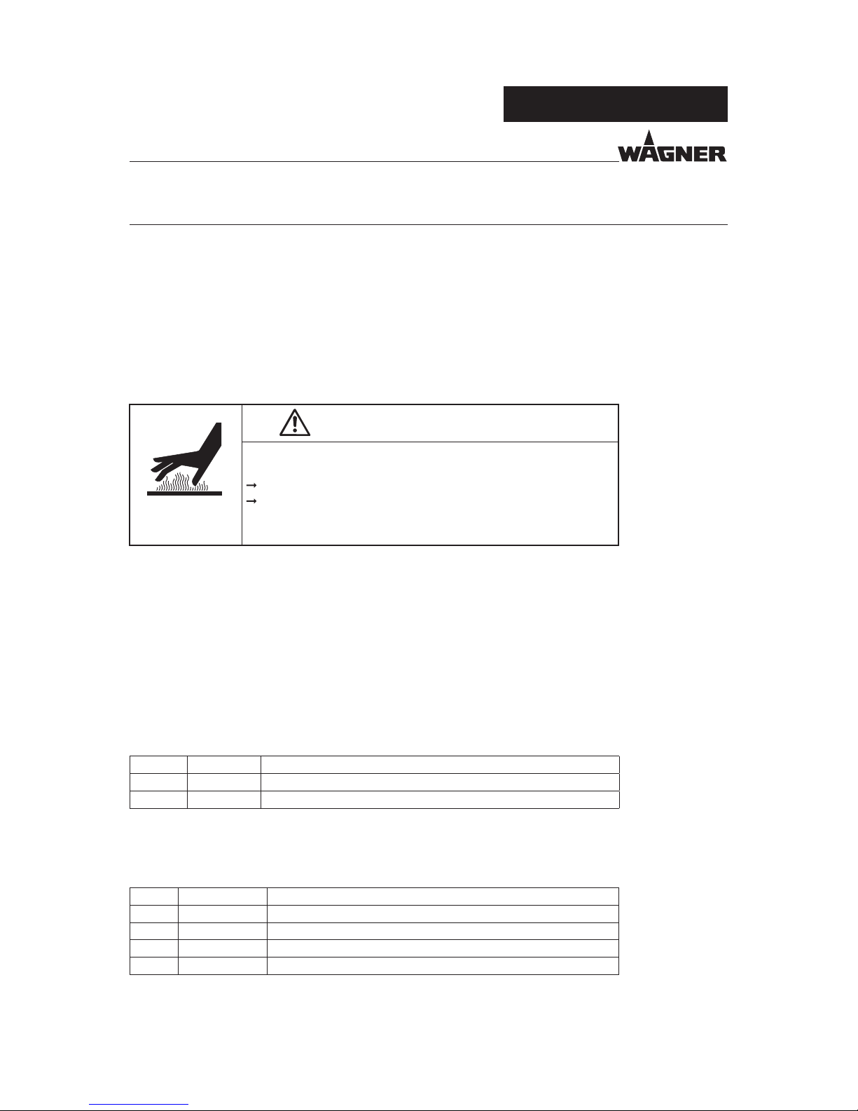
Wear suitable protective clothing when working with hot materials.
Touch hot surfaces only if you are wearing protective gloves.
When operating the unit with a coating material with a temperature of > 43 °C;109.4 °F:
- Identify the unit with a warning sticker "Warning - Hot Surface".
Order No.
9998910 Instruction sticker
9998911 Protection sticker
WAGNER accepts no liability for any damage arising from incorrect use.
Only use the unit to work with the materials recommended by WAGNER.
Only operate the unit as a whole.
Do not deactivate safety xtures.
Use only WAGNER original spare parts and accessories.
Page 9

9
GM 4700AC
OPERATING MANUAL
VERSION 09/2011
ORDER NUMBER DOC2311730
2.4.1 CORRECT USE
2.4.2 EXPLOSION PROTECTION IDENTIFICATION
2.4.3 MAXIMUM SURFACE TEMPERATURE
2.4.4 SAFETY INSTRUCTIONS
2.4 USE IN AN EXPLOSION HAZARD AREA
2.5 REFERENCE TO GERMAN REGULATIONS AND GUIDELINES
See chapter 3.3.
The unit is suitable for working liquid materials in accordance with the classi cation into
explosion classes.
X: The maximum surface temperature corresponds to the permissible material
temperature.
This and the permissible ambient temperature can be found in the "Technical Data"
chapter.
Safe handling of WAGNER spray units
Mechanical sparks can form if the unit comes into contact with metal.
In an explosive atmosphere:
Do not knock or push the unit against steel or rusty iron.
Do not drop the spray gun.
Use only tools that are made of a permitted material.
Ignition temperature of the coating material
Ensure that the ignition temperature of the coating material is above the maximum
surface temperature.
Medium supporting atomizing
To atomize the material, use only weakly oxidizing gases, e.g. air.
Cleaning
If there are deposits on the surfaces, the unit may form electrostatic charges. Flames or
sparks can form if there is a discharge.
Remove deposits from the surfaces to maintain conductivity.
As de ned in the Directive 94/9/EC (ATEX 95), the unit is suitable for use in areas where
there is an explosion hazard.
II 2G X
CE: Communautés Européennes
Ex: Symbol for explosion protection
II: Unit class II
2: Category 2 (Zone 1)
G Ex-atmosphere gas
X: Special Note
Page 10

10
GM 4700AC
OPERATING MANUAL
VERSION 09/2011
ORDER NUMBER DOC2311730
3.1 IMPORTANT NOTES ON PRODUCT LIABILITY
3.2 GUARANTEE CLAIM
3 GUARANTEE AND CONFORMITY DECLARATIONS
As a result of an EC regulation e ective from January 1, 1990, the manufacturer shall only
be liable for his product if all parts originate from him or are approved by him, and if the
devices are properly mounted, operated and maintained.
The manufacturer will not be held liable or will only be held partially liable if third-party
accessories or spare parts have been used.
With genuine WAGNER accessories and spare parts, you have the guarantee that all safety
regulations are complied with.
Full warranty is provided for this device to the following extent:
We will at our discretion repair or replace free of charge all parts which within 24 months
in single-shift, 12 months in 2-shift or 6 months in 3-shift operation from date of receipt by
the purchaser are found to be wholly or substantially unusable due to causes prior to the
sale, in particular faulty design, defective materials or poor workmanship.
The type of warranty provided is such that the device or individual components of the
device are either replaced or repaired as we see t. The resulting costs, in particular
shipping charges, road tolls, labour and material costs will be borne by us except where
these costs are increased due to the subsequent shipment of the unit to a location other
than the address of the purchaser.
We do not provide guarantee for damage that has been caused or contributed to for the
following reasons:
Unsuitable or improper use, faulty installation or commissioning by the purchaser or a
third party, normal wear, negligent handling, defective maintenance, unsuitable coating
products, substitute materials and the action of chemical, electrochemical or electrical
agents, except when the damage is attributable to us.
Abrasive coating products such as red lead, emulsions, glazes, liquid abrasives, zinc
dust paints and so forth reduce the service life of valves, packaging, spray guns, nozzles,
cylinders, pistons etc. Wear and tear due to such causes are not covered by this guarantee.
Components that have not been manufactured by WAGNER are subject to the original
warranty of the manufacturer.
Replacement of a component does not extend the period of warranty of the device.
The unit should be inspected immediately upon receipt. To avoid losing the warranty, we
or the supplier company are to be informed in writing about obvious faults within 14 days
upon receipt of the device.
We reserve the right to have the warranty compliance met by a contracting company.
The services provided by this warranty is dependent on evidence being provided in the
form of an invoice or delivery note. If the examination discovers that no warranty claim
exists, the costs of repairs are charged to the purchaser.
It is clearly stipulated that this warranty claim does not represent any constraint on statutory
regulations or regulations agreed to contractually in our general terms and conditions.
J. Wagner AG
Page 11

11
GM 4700AC
OPERATING MANUAL
VERSION 09/2011
ORDER NUMBER DOC2311730
3.3 CE DECLARATION OF CONFORMITY
Herewith we declare that the supplied version of
GM 4700AC 25 MPa
GM 4700AC-H 25 MPa
complies with the following guidelines:
2006/42/EG
94/9/EG
Applied standards, in particular:
DIN EN ISO 12100-1, 2004 DIN EN ISO 14121,2007
DIN EN ISO 12100-2, 2004 DIN EN ISO 3746, 2009
DIN EN 1127-1, 2008 DIN EN 13463-1, 2002
DIN EN 1953, 2010 DIN EN 13463-5: 2004
DIN EN ISO 13732-1, 2006
Applied national technical standards and speci cations, in particular:
a) BGR 500 Part 2, chapter 2.36 "Working with liquid ejection devices"
b) BGR 500 Part 2, chapter 2.29 "Working with coating materials"
c) BGR 104 Explosion protection rules
d) TRBS 2153 Avoiding ignition risks
e) BGI 740 Painting rooms and equipment
f) ZH 1/406 Guidelines for liquid ejection devices
Note: All titles can be ordered from Heymanns Publishing House in Cologne, or
they can be found on the Internet.
CE Certi cate of Conformity
The CE certi cate of conformity is enclosed with this product. If needed, further copies
can be ordered through your WAGNER dealer by specifying the product name and serial
number.
Order number: 2316429
Page 12
12
GM 4700AC
OPERATING MANUAL
VERSION 09/2011
ORDER NUMBER DOC2311730
The gun is suitable for atomizing liquid materials, particularly coating materials, using the
AirCoat process.
Note:
Please contact your local WAGNER dealer and the paint manufacturer if you encounter
application problems.
4 DESCRIPTION
Qty Order No. Description
1 2313585 GM 4700AC 25 MPa, NPSM1/4“ material connection
1 2315700 GM 4700AC-H 25 MPa, NPSM1/4“ material connection
These AirCoat gun is available in two di erent variants. The choice of air cap and nozzle are
dependent on application, therefore these components are not included in the scope of
delivery. A selection guide of gun accessories can be found in chapter 8.
Qty Order No. Description
1 2316429 CE Declaration of Conformity
1 2311729 Operating manual German
1 See Chapter 1. Operating manual in local language
1 394335 Spring cap 16 MPa; 160 bar; 2320 psi
For special versions the delivery note applies.
4.2.2 STANDARD EQUIPMENT
4.1 FIELDS OF APPLICATION, USE IN ACCORDANCE WITH THE INSTRUCTIONS
4.1.1 PROCESSABLE MATERIALS
Top-coat paints, primer paints, corrosion protection solvents, textured paints, lyes, staining
solvents, clear paints, separating uid, etc. on a solvent or water basis. If you want to spray
working materials other than the aforementioned, please contact a Wagner representative.
4.2 SCOPE OF DELIVERY
4.2.1 VARIANTS FOR APPLICATION RANGE UP TO 25 MPA; 250 BAR; 3625 PSI
WARNING
Hot coating substances!
Burns
Wear antistatic protective gloves.
When operating the unit with a coating material with a
temperature of > 43 °C;109.4 °F: Identify the unit with a warning
label that says „Warning - Hot Surface“.
The standard equipment for guns includes:
Page 13
13
GM 4700AC
E
C
B
G
A
D
F
B_02378
OPERATING MANUAL
VERSION 09/2011
ORDER NUMBER DOC2311730
Metals Plastics
Tungsten carbide Stainless steel 1.4305 POM FPM
Stainless steel 1.4301 Stainless steel 1.4104 PTFE PA
4.3.1 MATERIALS OF WETTED PARTS
AirCoat Spray gun
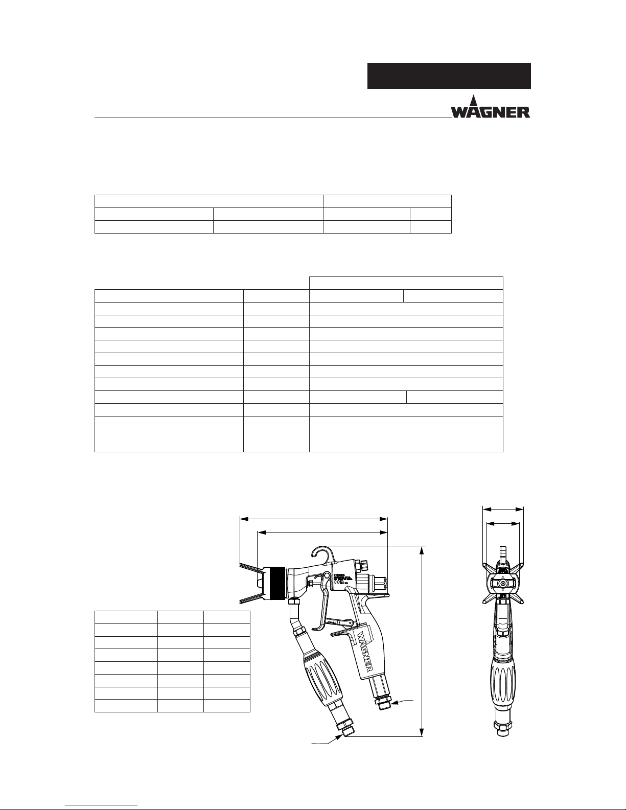
Description Units GM 4700AC GM 4700AC-H
Maximum air inlet pressure MPa/ psi/ bar 0.8/ 120/ 8
Maximum material pressure * MPa/ psi/ bar 25/ 3625/ 250 (16/ 2320/ 160*)
Fluid inlet Inch NPSM1/4
Air connection Inch G1/4“
Filter ** Mesh 50/ 100/ 150/ 200
Weight g/ oz 595 g/ 20.9 oz
pH range of the material pH 3.5 - 9.0
Maximum material temperature °C/ °F 55/ 131 80/ 176
Maximum air temperature °C/ °F 43/ 109
Sound level at 0.3 MPa; 3 bar; 43.5
psi air pressure and 11 MPa; 110
bar; 1549 psi material pressure ***
dB(A) < 82
* Spring cap type 16 MPa; 160 bar; 2320 psi is included
** Filter types see paragraph 8.4.
*** A rated sound pressure level measured at 0.5 m distance according to DIN EN 14462:2005
Dimensions
Measurement mm inch
A 173 6.81
B 216 8.50
C 48 1.89
D 152 5.98
E 39 1.54
F - NPSM1/4“
G - G1/4“
4.3.2 TECHNICAL DATA
4.3 DATA
Page 14
14
GM 4700AC
A
J
I
H
K
B
C
E
F
G
D
P_02379
OPERATING MANUAL
VERSION 09/2011
ORDER NUMBER DOC2311730
Description
A Suspension hook
B Regulator for shaping air
C Spring cap 16 MPa; 160 bar; 2320 psi
D Trigger
E Trigger locking device
F Air connection
G Fluid inlet
H Union nut with nozzle protection
I Nozzle / Air cap
J Gun housing
K Turning handle with lter housing
If trigger (D) is operated with released locking device (E), the air valve opens rst. Atomizing
air ows through air connection (F) to air cap (I). The material valve opens rst if approx.
1/2 of the trigger guard's path is covered. The quantity of air for the atomization of the jet
spray is preset via the external air automatic controller. The spray pattern can be adjusted
using shaping air regulator (B).
The spray gun is secured with locking device (E) (the locking device turned in the spraying
direction and fastened in the groove).
4.4 FUNCTIONAL DESCRIPTION
4.4.1 DESIGN OF THE SPRAY GUN
4.4.2 FUNCTIONS OF THE SPRAY GUN
Page 15

15
GM 4700AC
A
M
K
B
C
E D F G
H
J
L
I
B_02380
OPERATING MANUAL
VERSION 09/2011
ORDER NUMBER DOC2311730
5 COMMISSIONING AND OPERATION
5.1.1 TYPICAL AIRCOAT SPRAYING SYSTEM
A Material pump
B Pressure air shut-o valve
C Pressure regulator
D Air pressure regulator with air lter
E Grounding cable
F Air hose
The spray gun GM 4700 AC must be combined with various components to make up
a spraying system. The spraying system shown in the gure is only one example of an
AirCoat spraying system. Your Wagner distributor would be happy to assist you in creating
a spraying system solution that meets your individual needs.
You must familiarize yourself with the operating instructions and the safety regulations for
all additional system components before starting with commissioning.
5.1 INSTALLATION AND CONNECTION
G AirCoat gun
H High pressure paint hose,
electrically conductive
I High pressure lter/ uid pressure
release
J Return line
K Pump mounting trolley
L Suction system
M Compressed air main
WARNING
Incorrect installation/operation!
Risk of injury and damage to the device
When putting into operation and during all work, read and
follow the operating instructions and safety regulations for the
additional system components required.
Page 16

16
GM 4700AC
OPERATING MANUAL
VERSION 09/2011
ORDER NUMBER DOC2311730
5.1.2 VENTILATION OF THE SPRAY BOOTH
The use of an air lter with air regulator (D) ensures that only dry, clean atomizing air gets
into the spray gun! Dirt and moisture in the atomizing air worsens the spraying quality and
spraying pattern.
5.1.4 MATERIAL SUPPLY
5.1.3 AIR LINE
NOTICE
Impurities in the spraying system!
Spray gun blockage, materials harden in the spraying system
Flush the spray gun and paint supply with a suitable cleaning agent.
WARNING
Toxic and/or ammable vapor mixtures!
Risk of poisoning and burns
Operate the unit in a spray booth approved for the working
materials.
- or Operate the unit on an appropriate spraying wall with the
ventilation (suction) switched on.
Observe national and local regulations for the outgoing air
speed.
WARNING
Bursting hose, bursting threaded joints!
Danger to life from injection of material
Ensure that the hose material is chemically resistant to the
sprayed materials.
Ensure that the spray gun, threaded joints and material hose
between the unit and the spray gun is suitable for the pressure
generated in the unit.
Ensure that the following information can be seen on the high
pressure hose:
- Manufacturer
- Permissible operating pressure
- Date of manufacture
Page 17

17
GM 4700AC
OPERATING MANUAL
VERSION 09/2011
ORDER NUMBER DOC2311730
5.1.5 GROUNDING
A conductive connection (potential equalization cable) must be established between
original bundles and the equipment.
WARNING
Heavy paint mist if grounding is insu cient!
Risk of poisoning
Insu cient paint application quality
Ground all device components.
Ground the work pieces to be coated.
WARNING
Discharge of electrostatically charged components in
atmospheres containing solvents!
Explosion hazard from electrostatic sparks or ames
Ground all device components.
Ground the work pieces to be coated.
Page 18

18
GM 4700AC
OPERATING MANUAL
VERSION 09/2011
ORDER NUMBER DOC2311730
5.1.6 PRESSURE RELIEF
The pressure must always be relieved:
- when the spraying tasks are nished,
- before maintaining the spray system,
- before carrying out cleaning tasks on the spray system,
- before moving the system to another location,
- if something must be checked on the spray system, or
- if the nozzle or the lter is removed from the gun.
Pressure relief procedure:
1. Secure gun with locking device.
2. Close air supply to pump and relieve air pressure in air motor.
3. Release locking device on gun.
4. Press electrically conductive part of gun against grounded metal container for
return material and open the gun using the trigger guard; keep it open until no
further overpressure is detected.
5. Secure gun with locking device.
6. Open material pressure relief valve (see system description) and leave open.
If the pressure is still not completely relieved after this:
- - If nozzle is clogged: slowly loosen the union nut to release the remaining
pressure.
- - If material hose is obstructed: slowly loosen the hose connections to release the
remaining pressure.
Note:
Always follow the procedure described above if pressure relief is speci ed in the
instructions.
Please read the general safety instructions in chapter 2.
WARNING
High pressure spray jet!
Danger to life from injecting paint or solvent
Never reach into the spray jet.
Never point the spray gun at people.
Consult a doctor immediately in the event of skin injuries caused
by paint or solvent. Inform the doctor about the paint or solvent
used.
Never seal defective high pressure parts, instead relieve the
pressure from them and replace them.
Wear the appropriate protective clothing, gloves, eyewear, and
respiratory protection.
The components for pressure relief on a CE-compliant spray system are:
- Air cock with pressure relief hole mounted between compressed air source and
pneumatic pump.
- Material pressure relief valve mounted between pump and gun.
Page 19

19
GM 4700AC
P_02381
OPERATING MANUAL
VERSION 09/2011
ORDER NUMBER DOC2311730
5.3 COMMISSIONING
Locking device in secured
position
Air
Material
5.3.1 GENERAL RULES FOR MAKING ADJUSTMENTS TO THE SPRAY GUN
The viscosity of the paints is of great importance. The best spraying results are obtained
with values between 80 and 260 milli Pascal x Sec (mPas).
Please also read the technical data sheet of the paint for optimal processing, viscosity
adjustment and intermixing of the material.
5.2 PREPARATION OF PAINTS
CAUTION
Cleaning agent in the air duct!
Functional faults caused by swollen seals
Always point the spray gun down when cleaning.
Ensure that neither paint nor cleaning agents enter the air duct.
WARNING
Unintentional commissioning!
Risk of injury
Before any work on the device, in the event of work interruptions
and functional faults:
Switch o the energy/compressed air supply.
Relieve the pressure from the spray gun and unit.
Secure the spray gun against actuation.
In the event of functional faults: remedy the fault as described
in the "Trouble shooting" chapter.
Observe safety instructions in chapter 2.
Page 20

20
GM 4700AC
B_02261
x
OPERATING MANUAL
VERSION 09/2011
ORDER NUMBER DOC2311730
1. Secure the spray gun.
2. Connect material hose to the spray gun and material supply system.
3. Connect air hose to spray gun and to oil-free, dry air supply.
4. For guns with lters, insert suitable gun lter.
5. Place the nozzle into the nozzle seal. Fit the air cap over the nozzle. Take care with
the attened parts (X) of the nozzle and of the air cap. Fit the union nut with nozzle
guard and tighten by hand.
6. Visually check the permissible pressures for all the system components.
7. Make sure that the unit and all other conductive parts within the work area are
grounded.
8. Set operating pressure at 100 bar; 10 MPa; 1450 psi and use a suitable medium to
check that connections do not leak.
Note:
Pull the trigger and check that the gun closes cleanly upon release.
9. Relieve spray gun and unit pressure and secure the spray gun.
5.3.2 PREPARATION FOR COMMISSIONING
Page 21

21
GM 4700AC
B_00071
B_02382
OPERATING MANUAL
VERSION 09/2011
ORDER NUMBER DOC2311730
5.4 WORKS
Spray pattern shapes
No atomization air
Too little atomization air
Correct amount of atomization air
The spray pattern can be adjusted to suit the object being sprayed using the shaping air regulator. The
illustration below shows the in uence of the shaping air regulator on the spraying pattern Other nozzle sizes
can be used to obtain larger or smaller spraying patterns.
Shaping air
closed
Shaping air fully
open
Note:
The paint output volume can be changed by:
- changing the material pressure or
- Using a di erent at jet nozzle (see chap. 5.4.3 and chap. 8).
5.4.1 STARTUP FOR SPRAYING AIRCOAT
5.4.2 ADJUSTING THE SPRAY PATTERN
1. Start up with material supply set to approx. 8 MPa; 80 bar; 1160 psi operating pressure.
2. Spray (release locking device and pull trigger) and at the same time, check the atomization.
3. Set the uid pressure on the uid pump to the point where a good uid atomization is achieved.
4. Open the air pressure regulator for the atomizer air and adjust it so that an optimal atomization is
achieved. (The interrelation between spray pattern and atomizer air is shown in the gure below).
5. Use the shaping air controller on the gun to adjust the shaping air to atomizer air ratio, until the
optimal spray pattern is achieved.
Note:
Repeat points 4 and 5 until the optimum spray pattern has been found (iterative process).
Page 22

22
GM 4700AC
B_02261
x
A
B
C
D
B_02383
OPERATING MANUAL
VERSION 09/2011
ORDER NUMBER DOC2311730
5.4.3 CHANGING THE AIRCOAT NOZZLE
1. Relieve the pressure of gun and unit.
2. Secure gun with locking device.
3. Screw o union nut (A).
4. Remove air cap (B).
5. Press AirCoat nozzle (C) out of air cap (B) by hand and treat with cleaning solvent
until all remaining paint has been dissolved.
6. Assembly:
Place AirCoat nozzle (C) in nozzle seal (D).
7. Fit air cap (B) over nozzle (C). Take care with the attened parts (X) of the nozzle
and of the air cap.
8. Fit the union nut with nozzle guard (A) and tighten by hand.
CAUTION
Defective AirCoat nozzle!
Insu cient paint application quality.
Do not use sharp-edged objects to treat hard metal on the AirCoat nozzle.
Page 23

23
GM 4700AC
B_02261
x
A
B
C
D
B_02384
OPERATING MANUAL
VERSION 09/2011
ORDER NUMBER DOC2311730
For disassembly and assembly of AirCoat nozzles, see section 5.4.3.
AirCoat nozzle (C) can be placed into a cleaning solvent which has been recommended by
the paint manufacturer.
1. Relieve the pressure of gun and unit.
2. Secure gun with locking device.
3. Unscrew the union nut with nozzle guard (A).
4. Remove air cap (B).
5. Push AirCoat nozzle (C) out of air cap (B) by hand, reverse it and put it towards the
rear onto nozzle seal (D).
6. Re t air cap (B) on nozzle (C). Take care with the attened parts (X) of the nozzle
and of the air cap.
7. Fit the union nut with nozzle guard (A) over air cap (B) onto the spray gun and
tighten by hand.
8. Switch the material pressure back on.
9. Turn the locking device to the spraying position and brie y pull trigger.
10. When the blockage has been ushed out, secure the gun with the locking device.
11. Relieve the pressure of gun and unit.
12. Unscrew the union nut with nozzle guard (A).
13. Remove air cap (B) and push AirCoat nozzle (C) out by hand. Clean the nozzle and
put it back on nozzle seal (D) in the spray position.
14. Re t air cap (B) on nozzle (C).
Take care with the attened parts (X) of the nozzle and of the air cap.
15. Fit the union nut with nozzle guard (A) over air cap (B) onto the spray gun and
tighten by hand.
16. Switch the material pressure and the air pressure back on.
Nozzle in „spray“ position
Nozzle in „cleaning“ position
5.4.4 CLEANING AIRCOAT NOZZLE
5.4.5 ELIMINATE NOZZLE CLOGGING
Page 24

24
GM 4700AC
OPERATING MANUAL
VERSION 09/2011
ORDER NUMBER DOC2311730
6.0 MAINTENANCE
Observe safety instructions in chapter 2.
The spray gun and the unit must be cleaned daily. Only use cleaning solvents recommended
by the paint manufacturer.
WARNING
Incorrect maintenance/repair!
Risk of injury and damage to the device
Have repairs and part replacements be carried out by specially
trained sta or a WAGNER service center.
Before all work on the unit and in the event of work interruptions:
- Switch o the energy/compressed air supply.
- Relieve the pressure from the spray gun and unit.
- Secure the spray gun against actuation.
Observe the operating and service instructions when carrying
out all work.
CAUTION
Cleaning agent in the air duct!
Functional faults caused by swollen seals
Never immerse the spray gun in cleaning agent.
Page 25

25
GM 4700AC
OPERATING MANUAL
VERSION 09/2011
ORDER NUMBER DOC2311730
Note:
Methylene chloride is not recommended as a ushing or cleaning solvent with this gun
or any system components.
1. Relieve the pressure of gun and unit.
2. Secure gun with locking device.
3. Connect the detergent supply.
4. Remove AirCoat nozzle and clean separately (See chapter 5.4.3).
5. Pressurize the cleaning supply to a maximum pressure of 4 MPa; 40 bar; 580 psi
and thoroughly ush the spray gun.
6. Relieve the pressure of gun and unit.
7. Secure gun with locking device.
8. Clean the spray gun body with a cleaning agent recommended by the
manufacturer and dry with a cloth or blow gun.
6.1 DECOMMISSIONING AND CLEANING.
NOTICE
Cleaning agent in the air duct!
Functional faults caused by swollen seals
Always point the spray gun down when cleaning.
Ensure that neither paint nor cleaning agents enter the air duct.
DANGER
Exploding gas / air mixture!
Danger to life from ying parts and burns
Never spray into a closed container.
Ground the container.
WARNING
Explosive atmosphere!
Explosive gases are produced when aluminium comes into contact
with halogenized hydrocarbons.
To clean aluminium, do not use liquids containing halogenized
hydrocarbons.
Page 26

26
GM 4700AC
P_02386
B_02385
A
D
C
B
OPERATING MANUAL
VERSION 09/2011
ORDER NUMBER DOC2311730
1. Decommissioning work and cleaning
2. Relieve the pressure of gun and unit.
3. Secure gun with locking device.
Material hose
4. Place size A open-ended wrench on the lower ats of the material connection and
counter hold it.
5. Loosen the material hose's nut with a size B open-ended wrench.
Air hose
4. Place size D open-ended wrench on the ats of the air connection and counter
hold it.
5. Loosen the air hose's nut with a size C open-ended wrench.
Assembly:
1. Fit the material hose or air hose by hand and tighten with the two open-ended
wrenches.
Note:
Do not unscrew the lter
housing. The upper nut
may only be unscrewed by
WAGNER- Service-Agency.
Description Spanner A Spanner B Spanner c Spanner D
GM 4700AC with lter NPS1/4“
Wrench size
19 mm
Wrench size
19 mm
Wrench size
17 mm
Wrench size
17 mm
0.75 inch 0.75 inch 0.67 inch 0.67 inch
6.2 REPLACING THE MATERIAL HOSE OR AIR HOSE
Page 27

27
GM 4700AC
B
A
B_03649
64
83
66
67
OPERATING MANUAL
VERSION 09/2011
ORDER NUMBER DOC2311730
1. Decommissioning work and cleaning
2. Relieve the pressure of gun and unit.
3. Secure gun with locking device.
4. Insert lter housing (67) into the turning handle, screw in manually with the turning handle and
tighten. Loosen the lter housing (67) manually with turning handle (66) and unscrew it. When the
material hose together with lter housing and lter insert have been exposed, push turning handle
(66) back onto the upper lter connection.
5. Pull lter insert (64) out of the lter housing (67).
6. Thoroughly clean all parts with cleaning agent.
Assembly:
7. Push cleaned or new lter insert (64) with opening downwards into lter housing (67).
8. Insert lter housing (67) into the turning handle, screw in manually with the turning handle and
tighten.
Spanner A Spanner B
size 13 mm
wrench
size 17 mm
wrench
0.51 inch 0.67 inch
Note:
Do not unscrew lter
connection. The nut may only
be unscrewed by a WAGNERService Station.
6.3 CHANGING OR CLEANING FILTER INSERT
Procedure if connection is
di cult to loosen:
Loosen lter housing (67) with
wrench size B open-end wrench,
supporting the lter connection
with SW A open-end wrench.
open
close
Page 28

28
GM 4700AC
5
2
3
4
18
19
10
10
11
12
34
50
51
53
52
20
21
B
A
22
B_02388
OPERATING MANUAL
VERSION 09/2011
ORDER NUMBER DOC2311730
6.4 REPLACING PARTS ON THE VALVE ROD
1. Decommissioning work and cleaning
2. Relieve the pressure of gun and unit.
3. Secure gun with locking device.
4. Unscrew spring cap (5) using a size 15 (0.59 inch) wrench and remove pressure
springs (2) and (3).
5. Loosen screw (22) and remove together with nut (20).
6. Remove trigger guard (21).
7. Loosen sealing screw (10) with a size 7 mm (0.28 inch) single open-end wrench.
8. Carefully pull valve rod unit (B), together with sealing screw (10), rearwards out of
gun housing (A).
9. Hold tension sleeve (4) with a size 6 mm (0.24 inch) open-end wrench and loosen
collet chuck (18) with a size 5 mm (0.20 inch) open-end wrench.
10. Carefully pull valve rod (34) out forwards. Replace relevant parts.
6.4.1 DISASSEMBLY
CAUTION
Unsuitable tool!
Damage to seals and sealing surfaces
Do not hold the valve rod with pliers or a similar tool.
Page 29

29
GM 4700AC
B_02268
21
22
35
84
50
51
52
53
B_02274
B_02688
OPERATING MANUAL
VERSION 09/2011
ORDER NUMBER DOC2311730
6.4.2 REPLACEMENT OF VALVE TAPPET SEALS
6.4.3 REPLACING ROD SEAL 35
1. Carefully pull rod seal (35) out of the gun housing.
2. Clean sealing surfaces in the gun housing.
3. Mount new rod seal (35) to rod seal tool (84).
Spraying
direction
1. Counter hold with size 13 mm; 0.51 inch open-end wrench on valve
tappet (50) and unscrew cover (53) with a size 7 mm; 0.28 inches single
open-end wrench.
2. Remove air valve seal (51) and seal (52) and replace with new seals.
For the assembly of the air valve seal (51) a special tool (order number
179989) is necessary.
3. Screw valve tappet (50) and cover (53) together by hand. In small
increments, carefully tighten with a size 7 mm; 0.28 inch open-end
wrench and a size 13 mm; 0.51 inch wrench until a slight resistance is
perceptible when moving the valve rod (34) in the valve tappet.
Note:
Seal (52) can be pulled out of cover (53) with the help of an eye bolt.
Note:
Note installation position of
rod seal (35).
4. Insert rod seal tool (84) together with rod seal (35) into the hole.
5. Fit trigger guard (21) with screw (22) to body of gun and
6. carefully push the tool with rod seal (35) over trigger guard (21) into the
recess in the housing.
7. Remove trigger guard (21), screw (22) and rod seal tool (84).
Page 30

30
GM 4700AC
5
2
3
4
18
19
10
10
11
12
34
50
51
53
52
20
21
B
A
22
B_03650
85
5 Nm ±1
3.69 lbft
8 Nm ±1
5.90 lbft
87
86
87.9 mm ±0.15
OPERATING MANUAL
VERSION 09/2011
ORDER NUMBER DOC2311730
6.4.4 ASSEMBLY
1. Fit sealing collar (11) to valve rod (34), together with inserted O-ring (12) and sealing screw (10).
2. Push completely assembled valve tappet (19) onto valve rod (34).
3. Screw collet chuck (18) into clamping sleeve (4) (do not tighten).
4. Insert preassembled valve rod in to the preassembled clamping sleeve (4 and 18) up to stop.
5. Fix clamping sleeve (4) with size 6 mm/0.24 inch wrench, screw the preassembled valve rod to the
clamping sleeve and tighten (size 5mm;0.20 inch open-end wrench), tightening moment 5 1 Nm; 3.69
lbft. Note reference dimension.
6. Carefully insert complete valve rod (B) into the gun housing.
7. Screw in sealing screw (10) but do not tighten yet.
8. Position trigger guard (21) and secure with screw (22) and nut (20).
9. Insert pressure springs (3) and (2) and screw on spring cap (5), tightening moment 8 1 Nm; 5.90 lbft.
10. Carefully tighten the sealing collar (11, 12) over the sealing screw (10).
Ensure that the trigger guard moves easily.
11. Commissioning in accordance with chapter 5.3.
Note:
Only use silicone and resin free grease.
Page 31

31
GM 4700AC
16
17
14
13
36
33
B_02389
OPERATING MANUAL
VERSION 09/2011
ORDER NUMBER DOC2311730
6.5 REPLACING THE NOZZLE SEAL
1. Decommissioning work and cleaning
2. Relieve the pressure of gun and unit.
3. Secure gun with locking device.
4. Unscrew the union nut with nozzle guard (33).
5. Remove air cap (36) and nozzle (13).
6. Carefully release the nozzle seal (17) with the help of a screwdriver.
7. Fit new nozzle seal to valve housing (16).
8. Continue assembly in the reverse order.
CAUTION
Defective nozzle seal!
Material sprays into the air cap next to the nozzle
Risk of contamination
Do not clean the nozzle seal with sharp-edged objects.
Replace the nozzle seal if the sealing surface is damaged.
Page 32

32
GM 4700AC
4
1
3
2
14(F)
13
36
33
B_02390
OPERATING MANUAL
VERSION 09/2011
ORDER NUMBER DOC2311730
1. Decommissioning work and cleaning
2. Relieve the pressure of gun and unit.
3. Secure gun with locking device.
4. Unscrew the union nut with nozzle guard (33).
5. Remove air cap (36) and nozzle (13).
6. Remove defective sealing ring (14/F) with the help of pipe tongs or with a large
screwdriver.
7. Assembly: Fit new distributor seal (14/F) to air cap (36).
8. Place air cap, together with sealing ring (14/F), in gun body.
9. Attach union nut (33) and screw in until the sealing ring snaps into place in the
mounting groove (audible snap).
10. Demount union nut (33) and air cap (36) and complete spray gun according to
paragraph 5.4.3.
6.6 REPLACING THE "AIR" SEALING RING
CAUTION
Shaping air and atomizer air not separate!
Poor spray pattern
Spray jet cannot be adjusted.
Treat the distributor seal (F) with care.
Page 33

33
GM 4700AC
"?
"?
B_03060
E
D
B
C
A
B_02397
OPERATING MANUAL
VERSION 09/2011
ORDER NUMBER DOC2311730
6.7 CHANGING ROUND JET SEALING NIPPLE
Unscrew the nozzle by hand.
Note:
The sealing nipple (E) can be pulled out of the
nozzle housing using a small eye wood bolt.
Nozzle wrench (D)
order number 128901
Eject with 1.5 mm; 0.06 inch Ø pin.
Counter hold with a size 13
mm; 0.51 inch socket spanner.
NOTICE
Defective nozzle body!
Poor spray pattern
Handle the nozzle body (A) with care.
Page 34

34
GM 4700AC
OPERATING MANUAL
VERSION 09/2011
ORDER NUMBER DOC2311730
Functional fault Cause Remedy see chapter
Insu cient material
output
Nozzle too small Select larger nozzle. 8
Material pressure too
low
Increase material pressure.
Gun lter or high
pressure lter clogged at
pump
Clean or replace lter. 6.1
Nozzle is clogged Nozzle cleaning 5.4.5
The valve rod path is too
short.
Replace the valve rod. 6.4
Poor spray pattern Wrongly adjusted
atomizing air
Readjust the atomizing air. 5.4.1
The nozzle is too large. Select a smaller nozzle. 8.1
Material pressure too
low
Increase the material pressure at
pump.
The material viscosity is
too high.
Thin material in accordance with
the manufacturer's instructions.
The nozzle is partially
clogged.
Nozzle cleaning 5.4.5
The drilled holes in the
air cap are damaged or
clogged.
Clean or replace the air cap. 5.4.5
Incorrectly selected air
cap
Insert the correct air cap (solvent
/water based paint).
5.4.5
Valve rod leaks (paint
path or air path)
The seals on the valve
rod or the valve rod is
damaged.
Replace the entire valve rod or
the individual seals.
6.4
Air valve seals are leaky. Replace the air valve seal. 6.4
Pretension is too low. Tighten up the sealing screw.
Spray gun will not shuto correctly
The valve seat or the
valve ball is damaged.
Replace the parts. 6.4
Pretension of the seals is
too strong.
Replace the seals. 6.4
7 TROUBLE SHOOTING AND RECTIFICATION
Page 35

35
GM 4700AC
B_02277
B_02278
8.1.1
8.1.2
B_02398
8.1
OPERATING MANUAL
VERSION 09/2011
ORDER NUMBER DOC2311730
Order No. Description Marking Volumetric ow
rate*
Jet- **
132720 Nozzle insert R11 11 0.16; 160 Approx. 250; 9.84
132721 Nozzle insert R12 12 0.22; 220 Approx. 250; 9.84
132722 Nozzle insert R13 13 0.27; 270 Approx. 250; 9.84
132723 Nozzle insert R14 14 0.34; 340 Approx. 250; 9.84
132724 Nozzle insert R15 15 0.38; 380 Approx. 250; 9.84
132725 Nozzle insert R16 16 0.43; 430 Approx. 250; 9.84
132726 Nozzle insert R17 17 0.48; 480 Approx. 250; 9.84
132727 Nozzle insert R18 18 0.53; 530 Approx. 250; 9.84
132728 Nozzle insert R19 19 0.59; 590 Approx. 250; 9.84
132729 Nozzle insert R20 20 0.65; 650 Approx. 250; 9.84
132730 Nozzle insert R21 21 0.71; 710 Approx. 250; 9.84
132731 Nozzle insert R22 22 0.77; 770 Approx. 250; 9.84
* Volumetric ow in l/min; cc/min water at 10 MPa; 100 bar; 1450 psi
** Jet diameter in mm; inches at a distance of 30 cm; 11.8 inches from the object and at a pressure
of 10 MPa; 100 bar; 1450 psi, synthetic resin paint, 20 DIN 4 seconds.
8.1 ROUND JET NOZZLE CAP
Order No. Description
394180 Round jet nozzle cap (without
nozzle insert)
8 ACCESSORIES
Order No. Description
132922 Nozzle screw joint, complete
8.1.1 NOZZLE INSERTS RXX
8.1.2 COMPLETE NOZZLE SCREW JOINT
Page 36

36
GM 4700AC
10° 20° 30° 40° 50° 60° 80° inch
(mm) l/min (gal/min)
07 107 207 407
200
200
0,007 (0,18) 0,23 (0,061)
09 209 309 409 509 609 0,009 (0,23) 0,26 (0,069)
11 111 211 311 411 511 611 811
100
150
0,011 (0,28) 0,38 (0,100)
13 113 213 313 413 513 613 813
100
0,013 (0,33) 0,55 (0,145)
15 115 215 315 415 515 615 815 0,015 (0,38) 0,75 (0,198)
17 217 317 417 517 617 817
60
0,017 (0,43) 0,96 (0,254)
19 219 319 419 519 619 819
50
0,019 (0,48) 1,20 (0,317)
21 221 421 521 621 821 0,021 (0,53) 1,45 (0,383)
23 423 623 823 0,023 (0,58) 1,79 (0,473)
55
(2,17)
100
(3,94)
145
(5,71)
195
(7,68)
250
(9,84)
300
(11,81)
400
(15,75)
B_02399
B_02257
B_02256
B_02396
B_03764
OPERATING MANUAL
VERSION 09/2011
ORDER NUMBER DOC2311730
8.4 AIRCOAT NOZZLES ACF3000
Article No. 379xxx
In order to determine the article number of a nozzle, please select the
number from the table and replace the three xxx.
Example: nozzle 411 -> article number 379411
Spray angle
Material lter (mesh)
Gap- lter Gun lter
Drilled hole Material ow*
Shaping air width mm (inch)**
Size
* Tested with water and 100 bar pressure.
Tested with 110 bar (1595 psi), 30 cm (11.81 inches) distance and lacquer 56DIN-4s.
Order No. Description
2313494Air cap LV plus (red) for low viscosity paints
2313497 Air cap HV plus (blue) for high viscosity paints
2313498 Air cap LA plus (bronze)
Order No. Description
2330340
Complete anodized union nut (without air cap)
suitable for the processing of water-based coatings
8.2 AIR CAPS
8.3 ANODIZED UNION NUT
Page 37

37
GM 4700AC
B_02393
B_02689
B_02687
B_02689
B_02687
OPERATING MANUAL
VERSION 09/2011
ORDER NUMBER DOC2311730
8.5 FILTER INSERT
Order No. for 10
pieces
Filter sizes Mesh Use for nozzles
2315723 Filter insert, red 200 0.007“ - 0.011“
2315724Filter insert, blue 150 0.011“ - 0.013“
2315725 Filter insert, yellow 100 0.013“ - 0.019“
2315726Filter insert, white 50 0.019“ - 0.023“
Order No. Description
394933 Swivel set for material- (NPSM 1/4") and for air hose (G1/4")
394928 Swivel for material connection (NPSM 1/4“)
364938 Swivel for air connection G1/4“
8.6 SWIVEL JOINTS
Page 38

38
GM 4700AC
B_02685
B_02686
OPERATING MANUAL
VERSION 09/2011
ORDER NUMBER DOC2311730
Order No. Description
(All AC hose sets consist of a paint hose, an air hose and a protective hose.)
2309705 AC hose set DN3 PN270 1/4“NPS 7.5 m PA T
Material: 1/4“NPS, 7.5 m; 24.6 ft, DN 3; ID 0.12 inch, 27 MPa; 270 bar; 3916 psi
Air: G1/4“, 7.5 m; 24.6 ft, DN 6 mm; ID 0.24 inch, 1 MPa, 10 bar; 145 psi
2309706 AC hose set DN4 PN
270 1/4“NPS 7.5 m PA T
Material: 1/4“NPS, 7.5 m; 24.6 ft, DN 4; ID 0.16 inch, 27 MPa; 270 bar; 3916 psi
Air: G1/4“, 7.5 m; 24.6 ft, DN 6 mm; ID 0.24 inch, 1 MPa, 10 bar; 145 psi
2312801 AC hose set DN4 PN270 1/4“NPS 10.0 m PA T
Material: 1/4“NPS, 10 m; 32.8 ft, DN 4; ID 0.16
inch, 27 MPa; 270 bar; 3916 psi
Air: G1/4“, 10 m; 32.8 ft, DN 6 mm; ID 0.24 inch, 1 MPa, 10 bar; 145 psi
2309634 AC hose set DN4 PN270 1/4“NPS 15.0 m PA T
Material: 1/4“NPS, 15 m; 49.2 ft, DN 4; ID 0.16 inch, 27 MPa; 270 bar; 3916 psi
Air: G1/4“, 15 m; 49.2 ft, DN 6 mm; ID 0.24 inch, 1 MPa, 10 bar; 145 psi
2309635 AC hose set DN4 PN270 1/4“NPS 20.0 m PA T
Material: 1/4“NPS, 20 m; 65.6 ft, DN 4; ID 0.16 inch, 27 MPa; 270 bar; 3916 psi
Air: G1/4“, 20 m; 65.6 ft, DN 6 mm; ID 0.24 inch, 1 MPa, 10 bar; 145 psi
2322656 AC hose set DN3 PN270 1/4“NPS 3.0 m PA T
Material: 1/4“NPS, 3 m; 9.84 ft, DN 3; ID 0.12 inch, 27 MPa; 270 bar; 3916 psi
Air: G1/4“, 3 m; 9.84 ft, DN 6 mm; ID 0.24 inch, 1 MPa, 10 bar; 145 psi
3676437 Protective hose
8.7 HOSES
Order No. Description
9997001 Nozzle cleaning brush
394941 Service set GM 4600/ 4700AC
367560 Double connector NPSM1/4“ (outer thread), for material hose extension
9985720 Double nipple G1/4“ (outer thread), for air hose extension
2324747 Sealing collar UHMW-PE, complete, suitable for paints 2K-PU
8.8 MISCELLANEOUS
Page 39

39
GM 4700AC
OPERATING MANUAL
VERSION 09/2011
ORDER NUMBER DOC2311730
9 SPARE PARTS
9.1 HOW CAN SPARE PARTS BE ORDERED?
WARNING
Incorrect maintenance/repair!
Risk of injury and damage to the device
Have repairs and part replacements be carried out by specially
trained sta or a WAGNER service center.
Before all work on the unit and in the event of work interruptions:
- Switch o the energy/compressed air supply.
- Relieve the pressure from the spray gun and unit.
- Secure the spray gun against actuation.
Observe the operating and service instructions when carrying
out all work.
Always supply the following information to ensure delivery of the right spare part:
Order number, designation and quantity
The quantity need not be the same as the numbers given in the quantity column "Stk"
on the list. This number merely indicates how many of the respective parts are used in
each module.
The following information is also required to ensure smooth processing of your order:
- Address for the invoice
- Address for delivery
-Name of the person to be contacted in the event of any queries
- Type of delivery required (air freight or mail, sea route or overland route, etc.)
Identi cation in spare parts lists
Explanation of column "K" (labeling) in the following spare parts lists.
Wearing parts
Note: No liability is assumed for wearing parts.
Not part of standard equipment, available however, as an extra.
Page 40

40
GM 4700AC
OPERATING MANUAL
VERSION 09/2011
ORDER NUMBER DOC2311730
9.2 SPARE PARTS LIST GM 4700AC
Spare parts lists GM 4700AC
Pos K Qty
16 MPa 25 MPa
Description
Order No. Order No.
1
1 --- 2313585
GM 4700AC 25 MPa NPSM1/4“
2
1 9999501 9999501
Helical spring material
3 1 9999500 9999500 Helical spring air
4123121402312140 Te nsion sleeve
5
1 394335 -
Spring cap 16 MPa; 160 bar; 2320 psi
5
1-394333
Spring cap 25 MPa; 250 bar; 3625 psi
6 1 394924 394924Air tappet, complete
8 1 2311320 2311320 Valve rod unit, complete
10
1 394327 394327
Sealing screw
11 1 394328 394328 Sealing collar
11 1 2324747 2324747 Sealing collar UHMW-PE, complete (including item 12)
12 1 9971445 9971445 O-ring
13 1 379xxx 379xxx AC nozzle (See chapter 8.2)
14 1 394339 394339 Sealing ring
15 1 9974245 9974245 O-ring
16 1 394922 394922 Valve housing, complete
17 1 394338 394338 Seal nozzle
18 1 23121492312149 Collet chuck
19 1 394257 394257 Valve tappet, complete
20 1 394318394318 Nut
21
1 394601 394601
Trigger
22
1 394319394319
Screw
23
1 394334 394334
Locking device
24
1 9935088 9935088
Straight pin
25
1 394313394313
Air tappet
26 1 9974243 9974243 O-ring
27
1 394303 394303
Mounting bracket
28 1 9921906 9921906 Lock washer
29
1 2324766 2324766
Air swivel, complete
34 1 394920 394920 Valve rod, complete
35 1 394323 394323 Rod seal
36 1 2313494 2313494Air cap LV plus (red)
36 1 2313497 2313497 Air cap HV plus (blue)
36 1 2313498 2313498 Air cap LA plus (bronze)
50 1 394309 394309 Valve tappet
51
1179338 179338 Air valve seal
52 1179395 179395 Seal
= Wearing part
= Included in service set
= Not part of the standard equipment but available as a special accessory
Page 41

41
GM 4700AC
GM 4700AC
B_02391
5
4
18
19
10
12
34
50
51
52
25
27
28
22
80
82
21
20
14
15
16
17
13
55
56
57
58
59
60
61
63
62
36
84
24
23
2
3
8
B
5
36
85
64
66
67
83
6
1
26
35
11
86
87
53
88
36
80
29
65
OPERATING MANUAL
VERSION 09/2011
ORDER NUMBER DOC2311730
Mounting materials
Pos K Order No. Description
80
9992831 Loctite 542
81
9992833 Loctite 638 green
82
9992590 Loctite 222
83 9992609 Anti-sieze paste
84 394342 Tool valve rod seal
85 Molykote
86 9992528 Loctite 270
87 9992698 Vaseline white PHHV II
88 179989 Tool air valve seal
Detail B
Page 42

42
GM 4700AC
OPERATING MANUAL
VERSION 09/2011
ORDER NUMBER DOC2311730
Spare parts lists GM 4700AC
Pos K Qty
16 MPa 25 MPa
Description
Order No. Order No.
53 1 394322 394322 Cap
55 1 394336 394336 Nozzle body
56 1128327 128327 Sealing nipple
57 1132516 132516 Nozzle screw joint, complete
58 1132351132351 Nozzle screwed connection holder
59 1 394308 394308 union nut
60 1 394337 394337 Nozzle nut
61 1132... 132... Nozzle insert R (various dimensions: See chapter 8.1.1.)
62 1 394180 394180 Round jet nozzle cap (See chapter 8.1.)
63 1132922 132922 Nozzle screw joint, complete
64 1 2315723 2315723 Filter insert red (200 mesh)
64 1 2315724 2315724Filter insert blue (150 mesh)
64 1 2315725 2315725 Filter insert yellow (100 mesh)
64 1 2315726 2315726Filter insert white (50 mesh)
65 1128389 128389 Seal
66 1 2311491 2311491Turning handle
67 1 2320016 2320016 Filter housing, complete
1 394941 394941 Service set GM 4600/4700AC
= Wearing part
= Included in service set
= Not part of the standard equipment but available as a special accessory
Page 43

43
GM 4700AC
OPERATING MANUAL
VERSION 09/2011
ORDER NUMBER DOC2311730
9.3 SPARE PARTS LIST GM 4700ACH
Spare parts list GM 4700AC-H
Pos K Qty 25 MPa Description
Order No.
112315700 GM 4700AC-H, 25 MPa NPSM1/4“
2 1 9999501 Helical spring material
3 1 9999500 Helical spring air
412312140 Te nsion sleeve
5 1 394333 Spring cap 25 MPa; 250 bar; 3625 psi
6 1 394924Air tappet, complete
8 1 2311320 Valve rod unit, complete
10 1 394327 Sealing screw
11 1 394328 Sealing collar
11 1 2324747 Sealing collar UHMW-PE, complete (including item 12)
12 1 9971445 O-ring
13 1 379xxx AC nozzle (See chapter 8.2)
14 1 394339 Sealing ring
15 1 9974245 O-ring
16 1 394922 Valve housing, complete
17 1 394338 Seal Nozzle
18 1 2312149 Collet chuck
19 1 394257 Valve tappet, complete
20 1 394318 Nut
211394601Trigger
22 1 394319 Screw
23 1 394334Safety clip
2419935088 Straight pin
25
1 394313 Air tappet
26 1 9974243 O-ring
27
1 394303 Mounting bracket
28 1 9921906 Lock washer
29 1 2324766 Air swivel, complete
34 1 394920 Valve rod, complete
35 1 394323 Rod seal
36 1 2313494Air cap LV plus (red)
36 1 2313497 Air cap HV plus (blue)
36 1 2313498 Air cap LA plus (bronze)
50 1 394309 Valve tappet
51 1179338 Air valve seal
52 1179395 Seal
53 1 394322 Cap
= Wearing part
= Included in service set
= Not part of the standard equipment but available as a special accessory
Page 44

44
GM 4700AC
GM 4700AC-H
B_02392
65
5
4
18
19
10
12
34
50
51
52
25
27
28
22
80
82
21
20
14
15
16
17
13
55
56
57
58
59
60
61
63
62
84
24
23
2
3
8
B
85
64
66
67
83
6
1
26
35
11
86
87
53
70
69
88
36
36
36
80
29
OPERATING MANUAL
VERSION 09/2011
ORDER NUMBER DOC2311730
Mounting materials
Pos K Order No. Description
80
9992831 Loctite 542
81
9992833 Loctite 638 green
82
9992590 Loctite 222
83 9992609 Anti-sieze paste
84 394342 Tool valve rod seal
85 Molykote
86 9992528 Loctite 270
87 9992698 Vaseline white PHHV II
88 179989 Tool air valve seal
Detail B
Page 45

45
GM 4700AC
OPERATING MANUAL
VERSION 09/2011
ORDER NUMBER DOC2311730
Spare parts list GM 4700AC-H
Pos K Qty 25 MPa Description
Order No.
55 1 394336 Nozzle body
56 1128327 Sealing nipple
57 1132516 Nozzle screw joint, complete
58 1132351 Nozzle screwed connection holder
59 1 394308 union nut
60
1 394337 Nozzle nut
61
1132... Nozzle insert R (various dimensions see in chapter 8.1.1)
62 1 394180 Round jet nozzle cap (see chapter 8.1)
63 1132922 Nozzle screw joint, complete
64 1 2315723 Filter insert red (200 mesh)
64 1 2315724Filter insert blue (150 mesh)
64 1 2315725 Filter insert yellow (100 mesh)
64 1 2315726Filter insert white (50 mesh)
65 1128389 Seal
66 1 2311491Turning handle
67 1 2320016 Filter housing, complete
69 1 9998910 Instruction sticker "Hot Surfaces"
70 1 9998911 Protection sticker for 9998910
1 394941 Service set GM 4600/4700AC
= Wearing part
= Included in service set
= Not part of the standard equipment but available as a special accessory
Page 46

46
GM 4700AC
Germany
J. WAGNER GmbH
Otto-Lilienthal-Str. 18
Postfach 1120
D- 88677 Markdorf
Telephone: +49 7544 5050
Telefax: +49 7544 505200
E-Mail: service.standard@wagner-group.com
Switzerland
J. WAGNER AG
Industriestrasse 22
Postfach 663
CH- 9450 Altstätten
Telephone: +41 (0)71 757 2211
Telefax: +41 (0)71 757 2222
E-Mail: rep-ch@wagner-group.ch
Belgium
WSB Finishing Equipment
Veilinglaan 56/58
B- 1861 Wolvertem
Telephone: +32 (0)2 269 4675
Telefax: +32 (0)2 269 7845
E-Mail: info@wsb-wagner.be / HP www.wsb-wagner.eu
Denmark
WAGNER Industrial Solution Scandinavia
Viborgvej 100, Skærgær
DK- 8600 Silkeborg
Telephone: +45 70 200 245
Telefax: +45 86 856 027
E-Mail info@wagner-industri.com
United Kingdom
WAGNER Spraytech (UK) Ltd.
Haslemere Way
Tramway Industrial Estate
GB- Banbury, OXON OX16 8TY
Telephone: +44 (0)1295 265 353
Telefax: +44 (0)1295 269861
E-Mail: enquiries@wagnerspraytech.co.uk
France
J. WAGNER France S.A.R.L.
Parc de Gutenberg - Bâtiment F8
8, Voie la Cardon
F- 91127 Palaiseau-Cedex
Telephone: +33 1 825 011 111
Telefax: +33 1691 946 55
E-Mail: division.solutionsindustrielles@wagner-france.fr
Netherlands
WSB Finishing Equipment B.V.
De Heldinnenlaan 200
NL- 3543 MB Utrecht
Telephone: +31 (0) 30 241 4155
Telefax: +31 (0) 30 241 1787
E-Mail: info@wsb-wagner.nl / HP www.wsb-wagner.eu
Italy
WAGNER COLORA S.r.l
Via Fermi, 3
I- 20875 Burago di M
olgora (MB)
Telephone: +39 039 625021
Telefax: +39 039 6851800
E-Mail: info@wagnercolora.com
Japan
WAGNER Spraytech Ltd.
2-35, Shinden Nishimachi
J- Daito Shi, Osaka, 574-0057
Telephone: +81 (0) 720 874 3561
Telefax: +81/ (0) 720 874 3426
E-Mail: marketing@wagner-japan.co.jp
Austria
J. WAGNER GmbH
Otto-Lilienthal-Str. 18
Postfach 1120
D- 88677 Markdorf
Telephone: +49 (0) 7544 5050
Telefax: +49 (0) 7544 505200
E-Mail: service.standard@wagner-group.com
Sweden
WAGNER Industrial Solutions Scandinavia
Skolgatan 61
SE- 568 31 Skillingaryd
Telephone: +46 (0) 370 798 30
Telefax: +46 (0) 370 798 48
E-Mail: info@wagner-industri.com
Spain
WAGNER Spraytech Iberica S.A.
Ctra. N- 340, Km. 1245,4
E- 08750 Molins de Rei (Barcelona)
Telephone: +34 (0) 93 680 0028
Telefax: +34 (0) 93 668 0156
E-Mail: info@wagnerspain.com
Czechoslovakia
WAGNER s.r.o.
Nedasovská Str. 345
15521 Praha 5 - Zlicin
Telephone: +42 (0) 2 579 50 412
Telefax: +42 (0)2 579 51 052
E-Mail: info@wagner.cz
USA
WAGNER Systems Inc.
300 Airport Road, unit 1
Elgin, IL 60123 USA
Telephone: +1 630 503 2400
Telefax: +1 630 503 2377
E-Mail: info@wagnersystemsinc.com
OPERATING MANUAL
VERSION 09/2011
ORDER NUMBER DOC2311730
Page 47

Page 48

C
E
R
T
I
F
I
E
D
Order No. 2311730
Germany
J. WAGNER GmbH
Otto-Lilienthal-Str. 18
Postfach 1120
D- 88677 Markdorf
Telephone ++49/ (0)7544 / 5050
Telefax ++49/ (0)7544 / 505200
E-mail service.standard@wagner-group.com
Switzerland
J. WAGNER AG
Industriestrasse 22
Postfach 663
CH- 9450 Altstätten
Telephone ++41/ (0)71 / 757 2211
Telefax ++41/ (0)71 / 757 2222
www.wagner-group.com
 Loading...