

Page 1
magic clear, Regensensor zur automatischen Wischersteuerung · Rainsensor for automatic wiper
control · Sensor de lluvia para el control automático de los limpiaparabrisas · Détecteur de pluie pour
commande automatique des essuie-glace · Sensore pioggia per il comando automatico del
tergicristallo · Regensensor voor aurtomatische ruitenwisserbesturing · Regnsensor til automatisk
vinduesviskerstyring · Regnsensor för automatiska vindrutetorkare · Regnsensor for automatisk
styring av vindusviskere · Sadetunnistin ohjaa tuulilasinpyyhkijät automaattisesti
magic heat, Sitzheizung · seat heating · Calefacción del asiento · Chauffage du siège ·
Riscaldamento sedile · Stoelverwarming · Sædevarme · Sätesuppvärmning · Setevarmer ·
Istuinlämmitin
magic lift, Integrierter Universal-Fensterheber · Integrated universal electric windows · Elevalunas
integrados de uso universal · Lève-vitres universel intégré · Alzacristalli universale integrato ·
Geïntegreerde universele raamkruk · Integreret universal-rudehejs · Integrerad fönsterhiss · Integrert
universal-vindusløfter · Integroitu yleis-ikkunannostaja
magic light, Automatische Lichtsteuerung · Automatic light control · Control automático de las luces ·
Commande d’éclairage automatique · Comando luce automatico · Automatische lichtregeling ·
Automatisk lysstyring · Automatisk strålkastarstyrning · Automatisk lysstyring · Automaattinen valojen
ohjaus
magic lock, Universelle und fahrzeugspezifische Zentralverriegelungen · Universal and vehiclespecific central locking systems · Cierre centralizado universal y específico de cada vehículo ·
Verrouillages centralisés universels et spécifiques au véhicule · Chiusure centralizzate universali e
specifiche del veicolo · Universele en voertuigspecifieke centrale vergrendelingen · Universelle og
køretøjsspecifike centrallåse · Universella och fordonsspecifika centrallås · Universelle og spesielle
sentrallåser · Yleiset ja ajoneuvokohtaiset keskuslukitukset
magic touch, Universal-Funk-Fernbedienung für Zentralverriegelung · Universal remote control for
central locking · Mando a distancia universal para el control del cierre centralizado ·
Radiotélécommande universelle pour verrouillage centralisé · Radiotelecomando per chiusura
centralizzata · Universal-draadloze afstandsbediening voor centrale vergrendeling · Universel radiofjernbetjening til centrallås · Universell radio-fjärrkontroll för centrallås · Universal-fjernkontroll for
sentrallås · Yleinen radiokauko-ohjain keskuslukitukselle
magic safe, Auto-Alarmanlagen mit Fernbedienung · Vehicle alarm systems with remote control ·
Alarmas de automovil con mando a distancia · Systèmes d’alarme protecteur d’automobile avec
télécommande · Impianto di allarme auto con telecomando · Auto-alarminstallaties met
afstandsbediening · Auto-alarmanlæg med fjernbetjening · Bil-larmanläggningar med fjärrkontroll · Bilalarmanlegg med fjernkontroll · Autohälyttimet kauko-ohjauksella
magic speed, Automatische Geschwindigkeitsregler · Automatic cruise controls · Regulador
automático de la velocidad · Régulateur de vitesse automatique · Regolatore di velocità automatico ·
Automatische snelheidsregelaar · Automatisk fartpilot · Automatiska farthållare · Automatisk
hastighetskontroll · Automaattinen nopeudensäädin
magic watch, Universelle Ultraschall-Rückfahrwarner · Universal ultrasonic reversing signallers ·
Sensor indicador ultrasónico de marcha atrás universal · Avertisseur de recul universel, par ultrasons ·
Avvisatore universale a ultrasuoni per marcia indietro · Universele ultrasoon-achteruitrijwaarschuwing ·
Universelle ultralyds-bakalarmer · Universella ultraljuds-backsensorer · Universell ultralyd-ryggevarsel ·
Yleinen ultraääni-peruutusvaroitin
Ausführliche Informationen über die magic · Detailed information about magic is available from ·
Para obtener más información sobre magic · Pour de plus amples détails sur les produits magic ·
Informazioni dettagliate tramite la magic · Uitvoerige informatie over de magic · Udførlige
informationer om magic · Mer information om magic · Utførlige informasjoner om magic
Yksityiskohtaiset tiedot magic-tuotteista:
WAECO International GmbH · D-48282 Emsdetten · Hollefeldstr. 63
Tel. 00 49(0) 25 72/87 91 91 · Fax 0049 (0) 25 72/87 93 91
Internet: http://www.waeco.com 08.2002
Die magic Produktgruppe
Typ MT-350
Zugelassen in:
Fore use in:
D, GB, E, F, I, NL,
DK, S, N, FIN, A
magic touch MT-350
D
Funk-Fernbedienung
21
GB
Radio Remote Control
39
✎✎
✎✎
✎
3
E
Mando a distancia por radio
57
F
Radiotélécommande
75
I
Radiotelecomando
93
NL
Draadloze afstandsbedienin
111
DK
Radio-fjernbetjening
129
S
Radio – fjärrkontroll
147
N
Radio-fjernkontrol
165
FIN
Radiokauko-ohjain
183
Symbole
021386
Montage- und Bedienungsanleitung
Installation and Operating Instructions · Instrucciones de montaje y de servicio · Instructions de
montage et de service · Istruzioni di montaggio e d’uso · Montage- en bedieningshandleiding ·
Monterings- og betjeningsvejledning · Monterings- och bruksanvisning · Monterings- og
bruksanvisning · Asennus- ja käyttöohje
Page 2
2
199
FIN
Käyttöjännite: 9 - 16 V DC
Lepovirranotto: 5 mA
Maks. tehonotto: 16 A lyhyaikainen
Käyttölämpötila: -40 ... +85 °C vastaanotin
-20 ... +60 °C lähetin
Lähetystaajuus: 433,92 MHz
Ulottuvuus: 10 m ... 20 m
Keskuslukituksen kytkentävirta: maks. 10 A
Vilkun kytkentävirta: maks. 2 x 5 A
Lisälähdön kytkentävirta: maks. 150 mA
Keskuslukituksen aktivoinnin aika: valinnaisesti 0,6/3,5 sek.
Vilkun aktivoinnin aika: 1 x 0,75 sek. / 2 x 0,75 sek./
päälle / pois
Käsilähettimen koko (pit. x lev. x syv.): 52 x 35 x 13 mm
Vastaanottimen koko (pit. x lev. x syv.): 97 x 140 x 32 mm
Tekniset tiedot
Page 3
198
Ulottuvuus on jopa 20 metriä vastaanottimen asennustavasta ja
häiriölähteiden lähetystehoista riippuen.
Käsilähetin lähettää jokaisen käytön yhteydessä uuden koodin
(vaihtuvakoodi). Jos käsiläteintä käytetään liian usein ilman että
vastaanotin vastaanottaa lähetyssignaalin, saattaa olla, että vastaanotin
ei välittömästi tunnista käsilähetintä. Käsilähetintä on tällöin painettava
yhä 1-2 kertaa. Viimeistään kolmannella kerralla vastaanotin tunnistaa
lähettimen.
Käyttöopas
Paristo on vaihdettava jos käsilähettimen ulottuvuus huononee
selittämättömistä syistä tai jos tarkastus-LED:t vilkkuvat lähetyksen
aikana.
Käytä vain vuotamattomia paristoja ja sähköisiin laitteisiin soveltuvia
paristoja. Pidä paristot lasten ulottumattomilla. Älä koskaan yritä ladata
paristoja, älä yritä avata ne, äläkä heitä niitä avotuleen.
Suojele ympäristöäsi! Käytety paristot eivät kuulu talousjätteisiin, vaan on
toimitettava erityisiin yleisillä paikoilla, kuten esimerkiksi automarkettien
yhteydessä oleviin säiliöihin tai palautettava myyjälle.
Ruuvaa kauko-ohjaimen alapuolella oleva ruuvi irti ja avaa käsilähetin.
Vaihda paristo uuteen. Tarkista pariston napaisuus (pariston tyyppi CR
2032 3 volttia). Plusnapa ylöspäin. Tälläisia paristoja saa muun muassa
valokuvausliikkeistä ja kultaseppäliikkeistä.
Laita kauko-ohjaimen kansi paikoilleen ja ruuvaa kolmet ruuvit jälleen
kiinni.
Pariston vaihto
3
➀
➁
➀
➁
➂
➃
➂
A
B
✎
Page 4
4
➀
➃
➄
➁ ➂
➅
➀
➁
➂
➃
➄
➅
D
C
197
FIN
Vaihe 1: Kytke sytytys päälle.
Vaihe 2: Paina seuraavaksi 10 sekunnin kuluessa jo käytössä
olevan käsilähettimen molemmat painikkeet yhtä aikaa. Laite on
nyt koodaustilassa. Vahvistuksena ajoneuvo lukittuu.
Vaihe 3: Paina uuden uuden käsilähettimen sinistä näppäintä
kunnes keskuslukitus avautuu ja vahvistaa täten uusi koodaus.
Vaihe 4: Testaa uusi käsilähetin. Jos uusi käsilähetin ei toimi,
edelliset vaiheet on suoritettava uudestaan.
Keskuslukituksen avaaminen/sulkeminen
Ajoneuvon avaamista ja sulkemista ohjataan käsilähettimen sinisellä
painikkeella. Kaksi vilkkuvalosignaalia vahvistavat avaamista. Sulkemista
vahvistaa yksi vilkkuvalosignaali.
Kun ajoneuvoa on avattu sisätilan valaistus kytkeytyy päälle ja sammuu
jälleen kun ajoneuvon sytytystä on kytketty tai 30 sekunnin kuluttua
(koskee vain negatiivisesti kytkettyjä ovikoskettimia).
Comfort-toiminnon kytkeminen
Comfort-toimintojen lähtöä kytketään päälle harmaalla painikkeella
(ainoastaan kun ajoneuvo on lukittuna). Vastaanottimen asetuksista
riippuen lähtö kytkeytyy päälle 10 sekunniksi tai kunnes lähetyspainiketta
painetaan. Comfort-toiminnon kytkeytymistä vahvistaa yksi
vilkkuvalosignaali.
Huomioi! Tämän comfort-toiminnon maksimaalinen antovirta
(miinuskytketty) ei saa ylittää 150 mA. Suurimpien käyttölaitteiden
ohjausta varten on käytettävä lisärelettä (MT-RELAY).
Huomioi – Vaara jäädä puristuksiin! Ikkunannostajaa ei
koskaan saa käyttää valvomatta.
Lähettimen ja vastaanottimen radioyhteydessä ei saa esiintyä häiriöitä,
jotta kaukolähettimen toiminta olisi moitteeton.
Käyttöopas
Käsilähettiminen jälkikoodaus
Page 5
196
Käsilähettimien kuittaaminen
Yhtä käsilähetintä voi poistaa käytöstä (esim. jos käsilähetin on
kadonnut), jos toimintakelpoiset käsilähettimet koodataan 5 kertaa
peräkkäin. Toimi alla olevassa luvussa "Käsilähettimien koodaus
jälkikäteen" kuvatulla tavalla.
Avaa ajoneuvo käsilähettimellä.
Istuudu ajoneuvoon. Ovien on suljettuina kiinni mutta ei lukossa.
Käsilähettimien koodaus jälkikäteen
Radiovastaanottimen asetukset
Ohje! Jotta radiovastaanottimen olisi mahdollista tunnistaa asetukset,
kytkintulppa on vedettävä irti etukäteen.
DIP katkaisija 1 (katso ✎ L ➀)
Tällä valintakatkaisijalla asetetaan keskuslukituksen ohjauksen releen
ohjausaika.
Asento On "3,5 sek."
Alkuperäinen keskuslukitus aktivoituu 3,5 sekunniksi.
Muutamat alkuperäiset paineilmakäyttöiset keskuslukitukset, joiden lukitus
kestää yli 0,6 sekunttia, käyttävät tätä asentoa.
Asento Off "0,6 sek."
Tämä asento koskee kaikkia sähkökäyttöisiä keskuslukituksia, joiden
lukitus yleensä kestää vähemmän kuin 0,6 sek.
DIP katkaisija 2 (katso ✎ L ➁)
Tällä valintakatkaisijalla säädetään comfort-toiminnon ohjaus.
Asento On
Lähtö on aktiivinen kun harmaa painiketta on painettu. Toisella
painalluksella lähetyspainike kytkeytyy päältä.
Asento Off
Kun harmaa painiketta on painettu lähtö on päällä vielä 10 sekunttia.
5
➀
D
➃
➀
➁
➂
➃
➀
➁
➂
10 mm
10 mm
15 mm
E
✎
F
G
Page 6
6
➃
➀
➁
➂
5 mm
➃
➀
➁
➂
5 mm
H
I
195
FIN
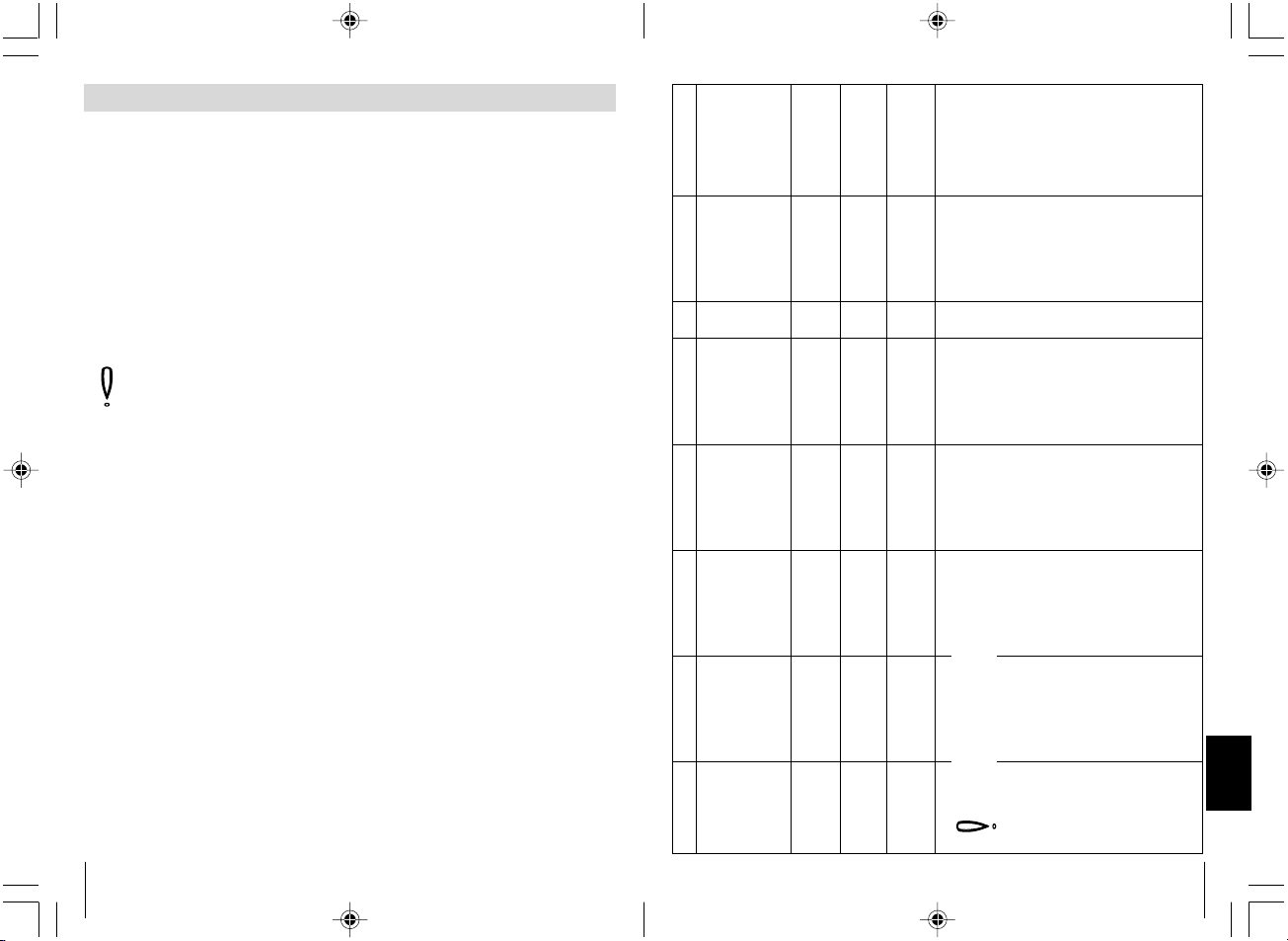
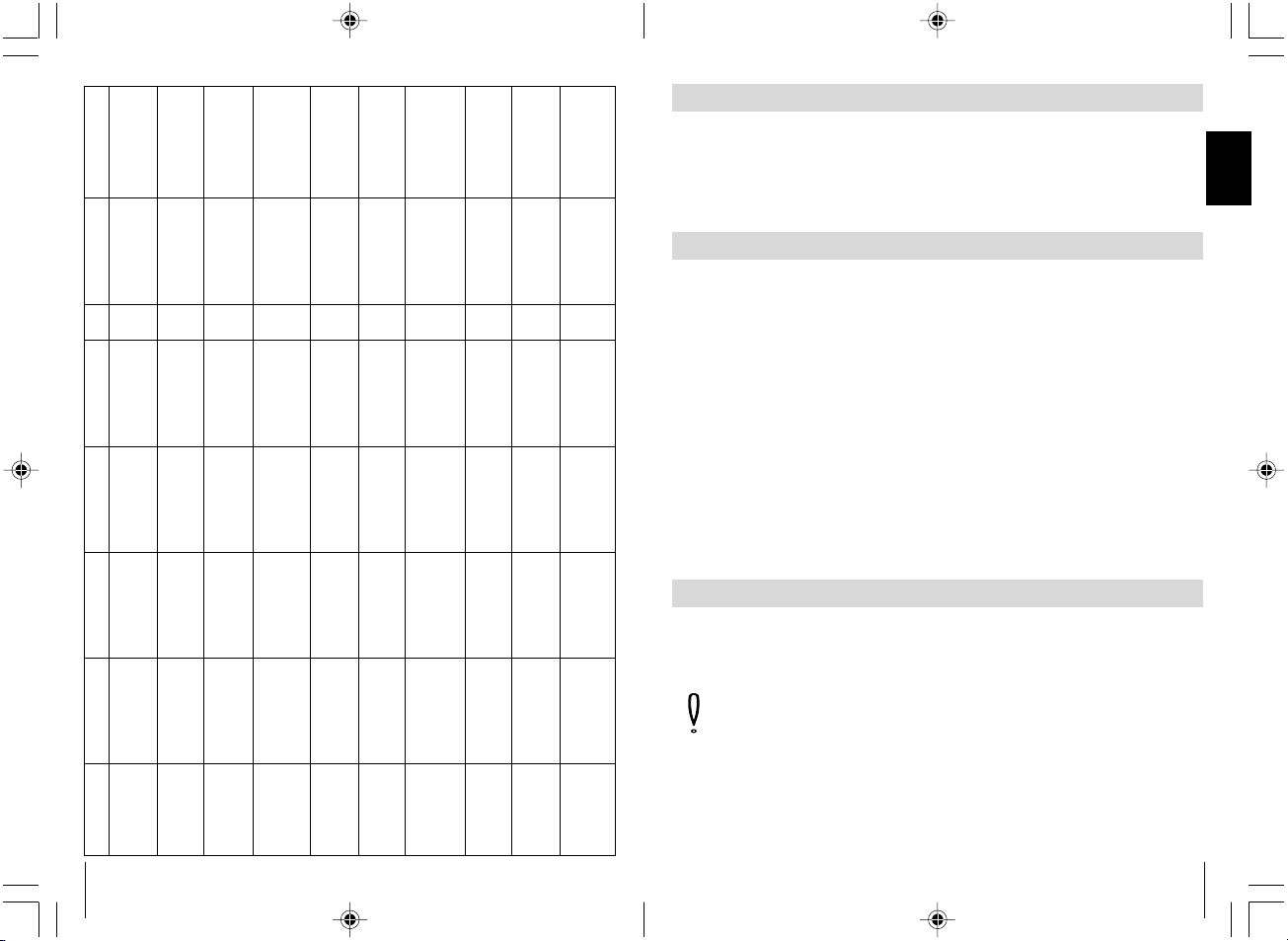
VW Passat 3B,
vuosimallit: 9/97-
VW Polo 6N,
vuosimallit: 95-
VW Sharan 7M,
vuosimallit: 96-
VW T4 vuosimallit:
93-
Vilkkuvalo links,
kaapelin väri, sijainti
musta/valkoinen,
kaapelointijärjestelmä
vasemmalla kynnyksellä
musta/valkoinen,
kaapelointijärjestelmä
vasemmalla kynnyksellä
musta/valkoinen,
kaapelointijärjestelmä
vasemmalla kynnyksellä
musta/valkoinen,
kaapelointijärjestelmä
vasemmalla kynnyksellä
Vilkku oikealla,
kaapelin väri, sijainti
Keskuslukitus
kaapelin väri, sijainti
Keskuslukitus
kaapelin väri, sijainti
Kytkentä-
suun.
Ovikosketin
kaapelin väri, sijainti
musta/vihreä,
kaapelointijärjestelmä
vasemmalla kynnyksellä
musta/vihreä,
kaapelointijärjestelmä
vasemmalla kynnyksellä
musta/vihreä,
kaapelointijärjestelmä
vasemmalla kynnyksellä
musta/vihreä,
kaapelointijärjestelmä
vasemmalla kynnyksellä
punainen/sininen / Pin 4
alkuperäiseltä
keskuslukituksen
ohjauslaitteelta
harmaa/musta,
A-pylväs vasemmalla,
kuljettajan ovesta tuleva
vihreä, A-pylväs
vasemmalla, kuljettajan
ovesta tuleva
keltainen, A-pylväs
vasemmalla, kuljettajan
ovesta tuleva
ruskea/sininen, Pin 2
alkuperäiseltä
keskusohjaukselta
harmaa/punainen,
A-pylväs vasemmalla,
kuljettajan ovesta tuleva
harmaa, A-pylväs
vasemmalla, kuljettajan
ovesta tuleva
valkoinen, A-pylväs
vasemmalla, kuljettajan
ovesta tuleva
Nro. 4
Nro. 3
Nro. 3
Nro. 3
ruskea/valkoinen,
A-pylvään kaapelin
läpiviennissä,
ovikosketin on
minuuskytketty
ruskea/valkoinen, ovikosk.
edessä vasemmalla
A-pylväällä, ovikosketin
on miinuskytketty
ruskea/valkoinen,
A-pylvään kaapelin
läpiviennissä, ovikosketin
on minuuskytketty
ruskea/valkoinen,
varokekotelon takana,
ovikosketin on
minuuskytketty
Ennen liittämistä on tarkastettava napaisuus.
Oikeudet muutoksiin pidätetään.
Tiedot muista ajoneuvoista pyynnöstä.
Huomautukset
Keskuslukitus on
maadoitusohjattu. Sin./pun.
johdossa on oltava 200 W
vastus, keskuslukituksen
ohjauslaite sijaitsee
mustassa laatikossa
kuljettajan puolella maton
alla.
Page 7
194
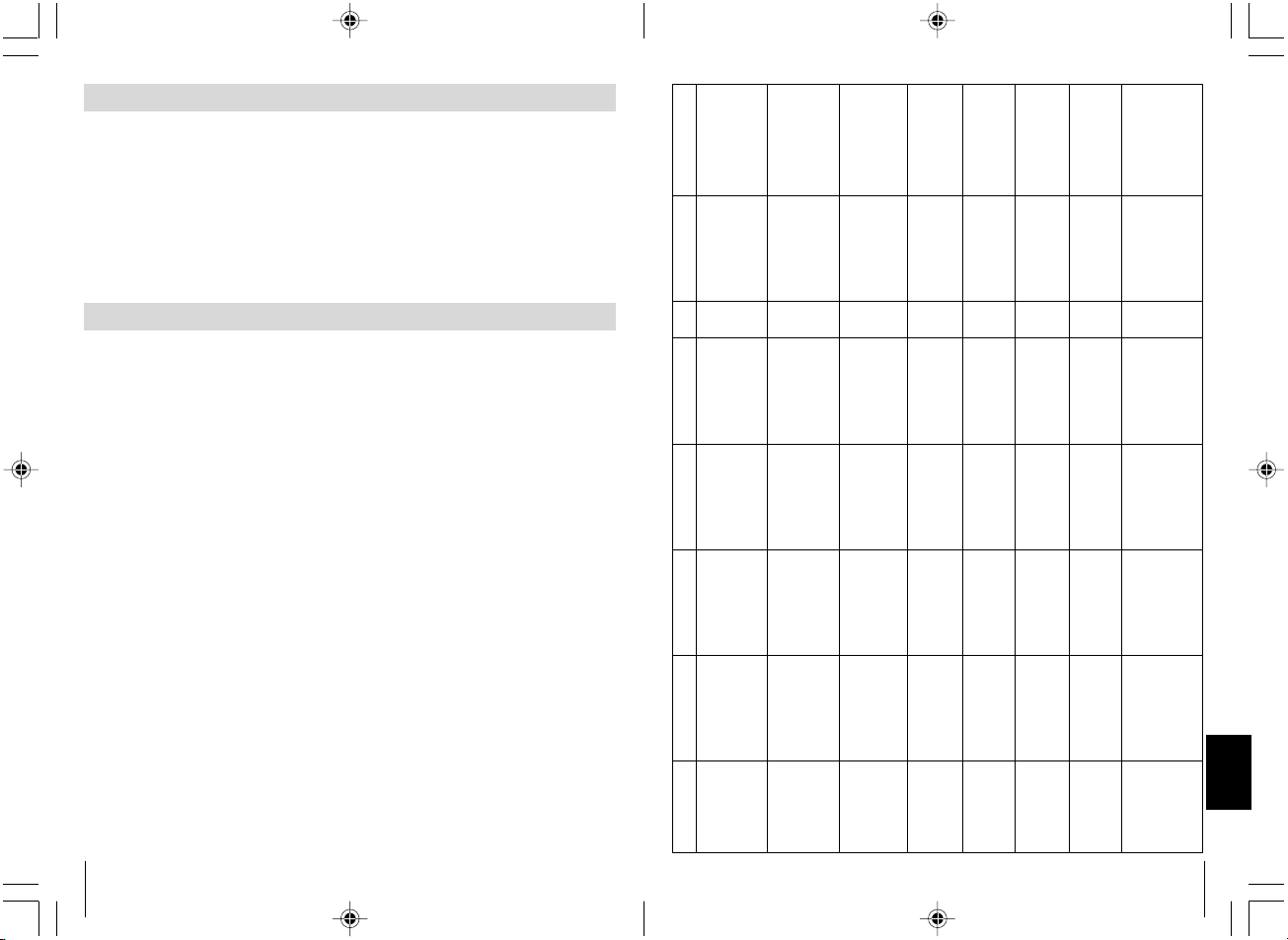
Opel Corsa A, B
vuosimallit: 93-2000
Opel Kadett E,
vuosimallit: 90-
Opel Omega A ja B,
vuosimallit: 90-
Opel Vectra A ja B
VW Golf lll ja Vento
Typ 1HXO,
vuosimallit: 91-
VW Golf lV
vuosimallit: 97-
sähköisellä
ikkunannostajalla
VW Golf lV
vuosimallit: 97-
ilman sähköistä
ikkunannostajaa
VW Lupo
vuosimallit: 98-
VW Passat 35i,
vuosimallit: 88-92
VW Passat 35i,
vuosimallit: 93-96
vilkkuvalo links,
kaapelin väri, sijainti
musta/valkoinen,
kaapelointijärjestelmä
vasemmalla kynnyksellä
musta/valkoinen,
kaapelointijärjestelmä
vasemmalla kynnyksellä
musta/valkoinen,
kaapelointijärjestelmä
vasemmalla kynnyksellä
musta/valkoinen,
kaapelointijärjestelmä
vasemmalla kynnyksellä
musta/valkoinen,
kaapelointijärjestelmä
vasemmalla kynnyksellä
musta/valkoinen,
kaapelointijärjestelmä
vasemmalla kynnyksellä
musta/valkoinen,
kaapelointijärjestelmä
vasemmalla kynnyksellä
musta/valkoinen,
kaapelointijärjestelmä
vasemmalla kynnyksellä
musta/valkoinen,
kaapelointijärjestelmä
vasemmalla kynnyksellä
musta/valkoinen,
kaapelointijärjestelmä
vasemmalla kynnyksellä
Vilkku oikealla,
kaapelin väri, sijainti
Keskuslukitus
kaapelin väri, sijainti
Keskuslukitus
kaapelin väri, sijainti
Kytkentä-
suun.
Ovikosketin
kaapelin väri, sijainti
Huomautukset
vihreä/musta,
kaapelointijärjestelmä
vasemmalla kynnyksellä
vihreä/musta,
kaapelointijärjestelmä
vasemmalla kynnyksellä
vihreä/musta,
kaapelointijärjestelmä
vasemmalla kynnyksellä
vihreä/musta,
kaapelointijärjestelmä
vasemmalla kynnyksellä
musta/vihreä,
kaapelointijärjestelmä
vasemmalla kynnyksellä
musta/vihreä,
kaapelointijärjestelmä
vasemmalla kynnyksellä
musta/vihreä,
kaapelointijärjestelmä
vasemmalla kynnyksellä
musta/vihreä,
kaapelointijärjestelmä
vasemmalla kynnyksellä
musta/vihreä,
kaapelointijärjestelmä
vasemmalla kynnyksellä
musta/vihreä,
kaapelointijärjestelmä
vasemmalla kynnyksellä
ruskea/valkoinen /
A-pylväs vasemmalla,
kuljettajan ovesta tuleva
ruskea/valkoinen,
A-pylväs vasemmalla,
kuljettajan ovesta tuleva
ruskea/valkoinen,
A-pylväs vasemmalla,
kuljettajan ovesta tuleva
ruskea/valkoinen,
A-pylväs vasemmalla,
kuljettajan ovesta tuleva
vihreä, A-pylväs
vasemmalla, kuljettajan
ovesta tuleva
keltainen/vihreä Pin 24,
oven ohjauslaitteella,
kuljettajan puolella
keltainen/vihreä,
keskuslaitteen
ohjauslaite harmaa
pistoke 24 napainen
kojelaudan alla
sininen/lila, A-pylväs
vasemmalla, kuljettajan
ovesta tuleva
musta/valkoinen,
A-pylväs vasemmalla,
kuljettajan ovesta tuleva
vihreä, A-pylväs
vasemmalla, kuljettajan
ovesta tuleva
ruskea/punainen /
A-pylväs vasemmalla,
kuljettajan ovesta tuleva
ruskea/punainen,
A-pylväs vasemmalla,
kuljettajan ovesta tuleva
ruskea/punainen,
A-pylväs vasemmalla,
kuljettajan ovesta tuleva
ruskea/punainen /
A-pylväs vasemmalla,
kuljettajan ovesta tuleva
harmaa, A-pylväs
vasemmalla, kuljettajan
ovesta tuleva
keltainen/sininen Pin 4,
oven ohjauslaitteella,
kuljettajan puolella
keltainen/sininen
keskuslaitteen
ohjauslaite harmaa
pistoke 24 napainen
kojelaudan alla
harmaa/keltainen,
A-pylväs vasemmalla,
kuljettajan ovesta tuleva
punainen/keltainen,
A-pylväs vasemmalla,
kuljettajan ovesta tuleva
harmaa, A-pylväs
vasemmalla, kuljettajan
ovesta tuleva
Nro. 4
Nro. 4
Nro. 4
Nro. 4
Nro. 3
Nro. 4
Nro. 4
Nro. 4
Nro. 3
Nro. 3
harmaa, ovikosk. edessä
vasemmalla A-pylväällä,
ovikosketin on
miinuskytketty
vihreä, ovikosk. edessä
vasemmalla A-pylväällä,
ovikosketin on
miinuskytketty
harmaa, ovikosk. edessä
vasemmalla A-pylväällä,
ovikosketin on
miinuskytketty
harmaa/valkoinen oder
ruskea/valkoinen, ovikosk.
edessä vasemmalla
A-pylväällä, ovikosketin
on miinuskytketty
ruskea/valkoinen, ovikosk.
edessä vasemmalla
A-pylväällä, ovikosketin
on miinuskytketty
ruskea/valkoinen, ovikosk.
edessä vasemmalla
A-pylväällä, ovikosketin
on miinuskytketty
sininen/harmaa,
keskuslukituksella,
ohjauslaite Pin 18:lla,
ovikosketin on
minuuskytketty
ruskea/valkoinen,
A-pylvään kaapelin
läpiviennissä, ovikosketin
on minuuskytketty
ruskea/valkoinen, ovikosk.
edessä vasemmalla
A-pylväällä, ovikosketin
on miinuskytketty
ruskea/valkoinen, ovikosk.
edessä vasemmalla
A-pylväällä, ovikosketin
on miinuskytketty
Oven ohjauslaite sijaitsee
ikkunannostajalla
oviverhoilun alla
Keskuslukituksen ohjauslaite
sijaitsee vasemmalla
ohjauspylvään vieressä.
Kaapelien värit löytyvät
myös A-pylväästä
7
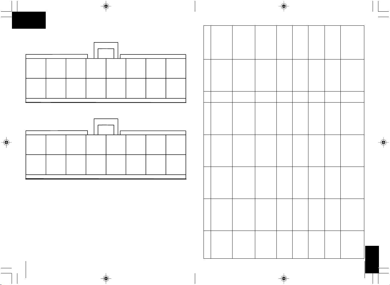
Antenne
Türkontakt
+ (plus) geschaltet
Türkontakt
- (minus) geschaltet
Masse (-) Kl. 31
Zündung +12 V
KL. 15
Komfortausgang
Masse (-) 150 mA max.
Blinker links
Blinker rechts
Frei
Batterie +12 V
Kl. 30
2
3
4
5
6
7
1
8
9
10
11
12
14
15
16
13
Zu
Auf
Schwarz
Grün
Gelb
Schwarz
Orange
Grün/rot
Schwarz/weiß
Schwarz/grün
Grau/gelb
Grau/rot
Rot/gelb
Blau/gelb
Blau/rot
Rot/schwarz
Rot
➀
J
✎
Page 8
8
7
Black/
white
14
Blue/
red
6
Green/
red
5
Orange4Black3Yellow
10
Grey/
yellow
2
Green
9
Free
1
Black
(Antenna)
13
Blue/
yellow
11
Grey/
red
12
Red/
orange
16
Red
15
Red/
black
8
Black/
green
7
Schwarz/
Weiß
14
Blau /
Rot
6
Grün /
Rot
5
Orange4Schwarz3Gelb
10
Grau /
Gelb
2
Grün
9
Frei
1
Schwarz
(Antenne)
13
Blau/
Gelb
11
Grau /
Rot
12
Rot /
Orange
16
Rot
15
Rot /
Schwarz
8
Schwarz/
Grün
➁
➁
J
193
FIN
BMW 3-sarja E36
vuosimallit: 93-
hälyttimellä
BMW 5-sarja E34,
vuosimallit: 88-95
BMW 5-sarja E34,
vuosimallit: 88-95
Mercedes 200-
W124, vuosimallit: -
95
Mercedes 190 W201,
vuosimallit: -94
Mercedes C180-
W202 vuosimallit: 94-
Opel Astra F ja G,
vuosimallit: 92-
Opel Calibra,
vuosimallit: 90-
Vilkku vasemmalla,
kaapelin väri, sijainti
sininen/vihreä,
kaapelointijärjestelmä
vasemmalla kynnyksellä
sininen/vihreä,
kaapelointijärjestelmä
vasemmalla kynnyksellä
sininen/vihreä,
kaapelointijärjestelmä
vasemmalla kynnyksellä
musta/valkoinen,
kaapelointijärjestelmä
vasemmalla kynnyksellä
musta/valkoinen,
kaapelointijärjestelmä
vasemmalla kynnyksellä
musta/valkoinen,
kaapelointijärjestelmä
vasemmalla kynnyksellä
musta/valkoinen,
kaapelointijärjestelmä
vasemmalla kynnyksellä
musta/valkoinen,
kaapelointijärjestelmä
vasemmalla kynnyksellä
vilkku oikealla,
kaapelin väri, sijainti
Keskuslukitus
kaapelin väri, sijainti
Keskuslukitus
kaapelin väri, sijainti
Kytkentä-
suun.
Ovikosketin
kaapelin väri, sijainti
Huomautukset
sininen/ruskea,
kaapelointijärjestelmä
vasemmalla kynnyksellä
sininen/ruskea,
kaapelointijärjestelmä
vasemmalla kynnyksellä
sininen/ruskea,
kaapelointijärjestelmä
vasemmalla kynnyksellä
musta/vihreä,
kaapelointijärjestelmä
vasemmalla kynnyksellä
musta/vihreä,
kaapelointijärjestelmä
vasemmalla kynnyksellä
musta/vihreä,
kaapelointijärjestelmä
vasemmalla kynnyksellä
vihreä/musta,
kaapelointijärjestelmä
vasemmalla kynnyksellä
vihreä/musta,
kaapelointijärjestelmä
vasemmalla kynnyksellä
Pin 25 / valkoinen 26
napainen pistoke
keskuslukitukselta
(9/91 saakka) Pin 2 tai
6, valk. 26 nap. pistoke
keskuslukitukselta
(9/91 lähtien) Pin 25,
valk. 26 nap. pistoke
keskuslukitukselta
Pin 16 / keltainen 26
napainen pistoke
keskuslukitukselta
sininen, A-pylväs
vasemmalla, kuljettajan
ovesta tuleva
sininen, A-pylväs
vasemmalla, kuljettajan
ovesta tuleva
sininen, A-pylväs
vasemmalla, kuljettajan
ovesta tuleva
ruskea/valkoinen, A-
pylväs vasemmalla,
kuljettajan ovesta tuleva
ruskea/valkoinen, A-
pylväs vasemmalla,
kuljettajan ovesta tuleva
Pin 19 / valkoinen 26
napainen pistoke
keskuslukituksen
ohjauslaitteelta
(9/91 saakka) Pin 1, valk.
26 nap. pistoke
keskuslukitukselta
(9/91 lähtien) Pin 24, valk.
26 nap. pistoke
keskusluki. ohjaukselta
Pin 7, keltainen 26
napainen pistoke
keskuslukituksen
ohjauslaitteelta
sininen, A-pylväs
vasemmalla, kuljettajan
ovesta tuleva
sininen, A-pylväs
vasemmalla, kuljettajan
ovesta tuleva
musta, A-pylväs
vasemmalla, kuljettajan
ovesta tuleva
ruskea/punainen,
A-pylväs vasemmalla,
kuljettajan ovesta tuleva
ruskea/punainen,
A-pylväs vasemmalla,
kuljettajan ovesta tuleva
Nro. 3
Nro. 3
Nro. 3
Nro. 6
Nro. 6
Nro. 4
Nro. 4
Nro. 4
ruskea/harmaa/keltainen,
ovikoskettimella edessä
vasemmalla B-pylväällä,
ovikosketin on
miinuskytketty
ruskea/lila,
ovikoskettimella,
edessä vasemmalla
B-pylväällä, ovikosketin
on miinuskytketty
ruskea/lila,
ovikoskettimella,
edessä vasemmalla
B-pylväällä
ruskea/valkoinen, ovikosk.
edessä vasemmalla
A-pylväällä, ovikosketin
on miinuskytketty
ruskea/valkoinen, ovikosk.
edessä vasemmalla
A-pylväällä, ovikosketin
on miinuskytketty
ruskea/valkoinen, ovikosk.
edessä vasemmalla
B-pylväällä, ovikosketin
on miinuskytketty
ruskea/valkoinen, ovikosk.
edessä vasemmalla
A-pylväällä, ovikosketin
on miinuskytketty
harmaa,ovikosk. edessä
vasemmalla A-pylväällä,
ovikosketin on
miinuskytketty
tarvitaan mahd. BMW
kosketusnasta numerolla
61131393704,
keskuslukituksen ohjauslaite
sijaitsee käsinelokeron
takana.
tarvitaan mahd. BMW
kosketusnasta numerolla
61131393704,
keskuslukituksen ohjauslaite
sijaitsee istuimen alla
tarvitaan mahd. BMW
kosketusnasta numerolla
61131393704,
keskuslukituksen ohjauslaite
sijaitsee istuimen alla
liitä sininen/keltainen
ohjausjohtolinja oven
suuntaan ja harmaa/
punainen johto
keskuslukituksen
pumpun suuntaan
liitä sininen/keltainen
ohjausjohtolinja oven
suuntaan ja harmaa/
punainen johto
keskuslukituksen
pumpun suuntaan
Page 9
192
Audi 80 mallit 89 ja
B4, vuosimallit: 86-
94
Audi 100 ja A6 malli
C4, vuosimallit: 90-
97 ilman
varkaudenestoa
Audi 100 ja A6 malli
C4, vuosimallit: 90 -
97 varkaudenestolla
Audi A3 malli 8L,
vuosimallit: 96-00
Audi A4 malli B5,
vuosimallit: 94-
ilman
varkaudenestoa
Audi A4 malli B5
vuosimallit: 94 -
varkaudenestolla
BMW 3-sarja E30,
vuosimallit: 82-90
BMW 3-sarja E36,
vuosimallit: 91-
BMW 3-sarja E36,
vuosimallit: 91-
Vilkku vasemmalla,
kaapelin väri, sijainti
musta/valkoinen,
kaapelointijärjestelmä
vasemmalla kynnyksellä
musta/valkoinen,
kaapelointijärjestelmä
vasemmalla kynnyksellä
musta/valkoinen,
kaapelointijärjestelmä
vasemmalla kynnyksellä
musta/valkoinen,
kaapelointijärjestelmä
vasemmalla kynnyksellä
musta/valkoinen,
kaapelointijärjestelmä
vasemmalla kynnyksellä
musta/valkoinen,
kaapelointijärjestelmä
vasemmalla kynnyksellä
vihreä/sininen,
30-napainen valkoinen
pistoke kojelaudan alla
sininen/vihreä,
kaapelointijärjestelmä
vasemmalla kynnyksellä
sininen/vihreä,
kaapelointijärjestelmä
vasemmalla kynnyksellä
Vilkkku oikealla,
kaapelin väri, sijainti
Keskuslukitus
kaapelin värille,sijainti
Kytkentä-
suun.
Ovikosketin, kaapelien
värit, sijainti
Huomatukset
musta/vihreä,
kaapelointijärjestelmä
vasemmalla oven
kynnyksellä
musta/vihreä,
kaapelointijärjestelmä
vasemmalla kynnyksellä
musta/vihreä,
kaapelointijärjestelmä
vasemmalla kynnyksellä
musta/vihreä,
kaapelointijärjestelmä
vasemmalla kynnyksellä
musta/vihreä,
kaapelointijärjestelmä
vasemmalla kynnyksellä
musta/vihreä,
kaapelointijärjestelmä
vasemmalla kynnyksellä
musta/vihreä / 30-
napainen valkoinen
pistoke kojelaudan alla
sininen/ruskea,
kaapelointijärjestelmä
vasemmalla kynnyksellä
sininen/ruskea,
kaapelointijärjestelmä
kynnyksellä
vihreä/sininen, A-pylväs
links
vihreä/sininen, A-pylväs
vasemmalla, kuljettajan
ovesta tuleva
ruskea/vihreä / A-pylväs
vasemmalla, kuljettajan
ovesta tuleva
harmaa/musta, A-pylväs
vasemmalla, kuljettajan
ovesta tuleva
vihreä/sininen /
A-pylväs vasemmalla,
kuljettajan ovesta tuleva
harmaa/valkoinen /
A-pylväs vasemmalla,
kuljettajan ovesta tuleva
vihreä/sininen,
keskuslukituksen
ohjauslaite Pin 6
Pin 25, valkoinen 26
napainen pistoke
keskuslaitteesta
Pin 4 / keltainen 26
napainen pistoke
keskuslaitteesta
vihreä/sininen, A-pylväs
vasemmalla
vihreä/sininen, A-pylväs
vasemmalla, kuljettajan
ovelta tuleva
ruskea/harmaa, A-
pylväs vasemmalla,
kuljettajan ovelta tuleva
ruskea/punainen tai
harmaa,
A-pylväs vasemmalla,
kuljettajan ovelta tuleva
vihreä/sininen /
A-pylväs vasemmalla,
kuljettajan ovelta tuleva
ruskea/harmaa /
A-pylväs vasemmalla,
kuljettajan ovelta tuleva
keltainen/sininen,
keskuslukituksen
ohjauslaite Pin 7
Pin 24, valkoinen 26
napainen pistoke
keskuslukitukselta
Pin 17 / keltainen 26
napainen pistoke
keskuslukitukselta
Nro. 6
Nro. 6
Nro. 4
Nro. 4
Nro. 6
Nro. 4
Nro. 4
Nro. 3
Nro. 3
ruskea/valkoinen ovikosk.
edessä vasemmalla
A-pylväällä, ovikosketin
on miinuskytketty
ruskea/keltainen, ovikosk.
edessä vasemmalla
A-pylväällä, ovikosketin
on miinuskytketty
ruskea/keltainen, ovikosk.
edessä vasemmalla
A-pylväällä, ovikosketin
on miinuskytketty
ruskea/valkoinen, ovikosk.
edessä vasemmalla
A-pylväällä, ovikosketin
on miinuskytketty
harmaa, ovikosk. edessä
vasemmalla A-pylväällä,
ovikosketin on
miinuskytketty
ruskea/valkoinen, ovikosk.
edessä vasemmalla
A-pylväällä, ovikosketin
on miinuskytketty
ruskea/keltainen, ovikosk.
edessä vasemmalla
A-pylväällä, ovikosketin
on miinuskytketty
ruskea/harmaa/keltainen,
ovikoskoskettimella
edessä vasemmalla
B-pylväällä, ovikosketin
on miinuskytketty
ruskea/harmaa/keltainen,
ovikoskettimella edessä
vasemmalla B-pylväällä,
ovikosketin on
miinuskytketty
sininen/keltainen
ohjausjohtolinja oven
suuntaan - liitä harmaa johto
keskuslukituksen pumppuun
sininen/keltainen
ohjausjohtolinja oven
suuntaan - liitä harmaa johto
keskuslukituksen pumppuun
sininen/keltainen
ohjausjohtolinja oven
suuntaan - liitä harmaa johto
keskuslukituksen pumppuun
keskuslukituksen pumppu
sijaitsee A-pylväässä
vasemmalla puolella
tarvitaan mahd. BMW
kosketusnasta numerolla
61131393704,
keskuslukituksen
ohjauslaite sijaitsee
käsinelokeron takana
tarvitaan mahd. BMW
kosketusnasta numerolla
61131393704,
keskuslukituksen
ohjauslaite sijaitsee
käsinelokeron takana
9
Batterie +12 V
Kl. 30
Antenne
Türkontakt
- (Masse) geschaltet
Masse (-) Kl. 31
Zündung +12 V
KL. 15
Blinker links
Blinker rechts
Frei
2
3
4
5
6
7
1
8
9
10
11
12
13
14
15
16
Gelb
Schwarz
Orange
Schwarz/weiß
Schwarz/grün
Rot
Zentralverriegelung
Schaltpläne
1 - 8
Blinker links
Blinker rechts
Klemme 30 (+ Batterie)
Klemme 15 (+ Zündung)
Klemme 31 (- Batterie)
Türkontaktschalter
Innenleuchte
Blinker Relais
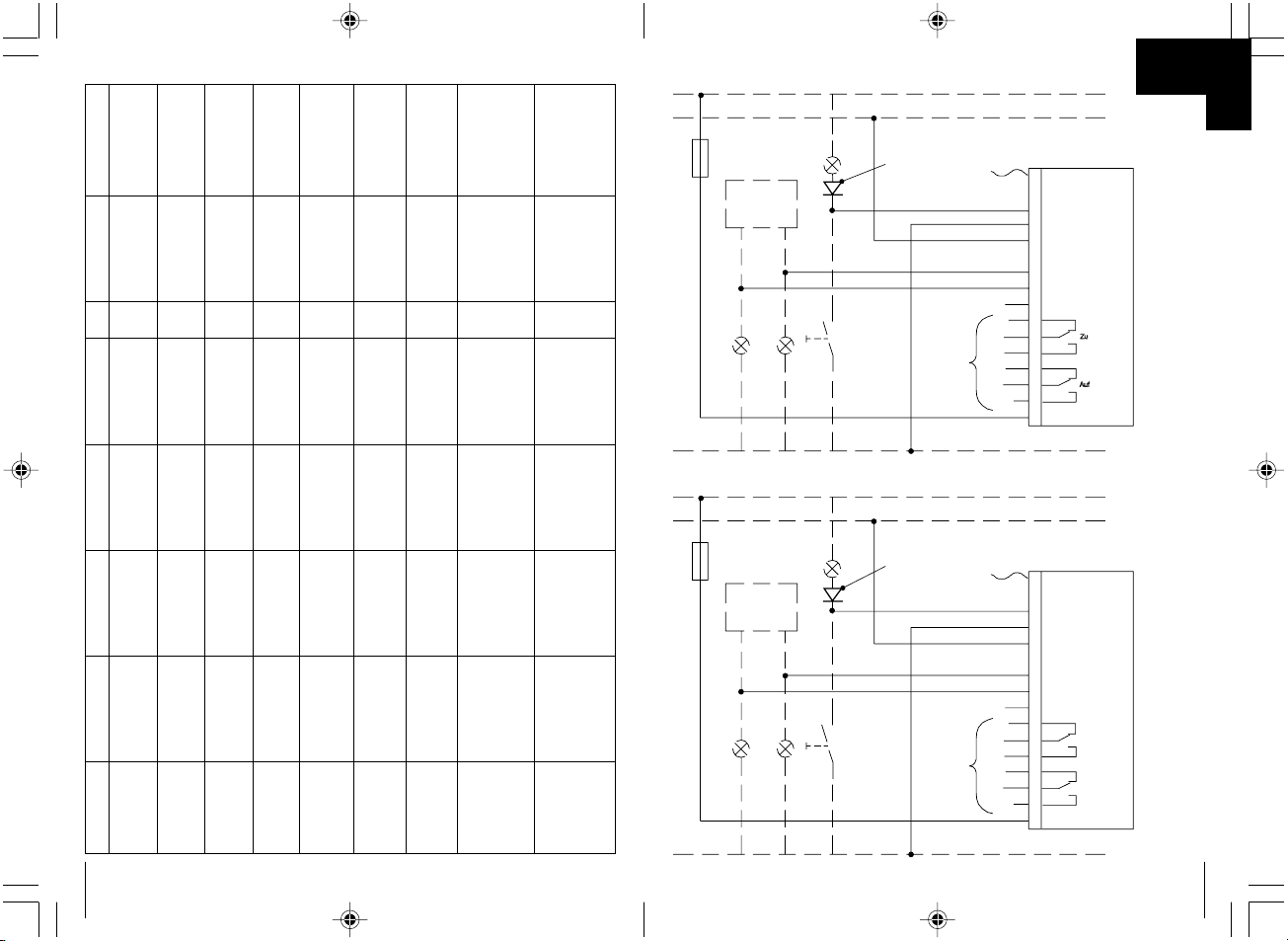
Hinweis! Wird die Innenleuchte beim Öffnen des
Fahrzeuges mit dem Schlüssel eingeschaltet, muss eine
Diode 1N4002 (Siehe Schaltplan) eingesetzt werden
➂
Battery +12 V
Terminal.30
Antenna
Door contact switch
- (negativ) switching
Ground (-) Terminal 31
Ignition +12 V
Termianl 15
Left blinker
Right blinker
Free
2
3
4
5
6
7
1
8
9
10
11
12
13
14
15
16
Yellow
Black
Orange
Black/white
Black/green
Red
Connection to
central locking
Circuit diagram
1-8
Left blinker
Right blinker
Terminal 30 (+ Battery)
Terminal 15 (+ Ignition)
Terminal 31 (- Battery)
Door contact
switch
Dome light
Blinker Relay
Close
Open
Note! If the dome light switched on when the door will
be unlocked by the key then a diode 1N4002 is
necessary
➂
J
✎
Page 10
10
Battery +12 V
Terminal.30
Antenna
Door contact switch
+ (positive) switching
Ground (-) Terminal 31
Ignition +12 V
Termianl 15
Left blinker
Right blinker
Free
2
3
4
5
6
7
1
8
9
10
11
12
13
14
15
16
Green
Black
Orange
Black/white
Black/Green
Red
Connection to
central locking
Circuit diagram
1-8
Left blinker
Right blinker
Terminal 30 (+ Battery)
Terminal 15 (+ Ignition)
Terminal 31 (- Battery)
Door contact
switch
Dome light
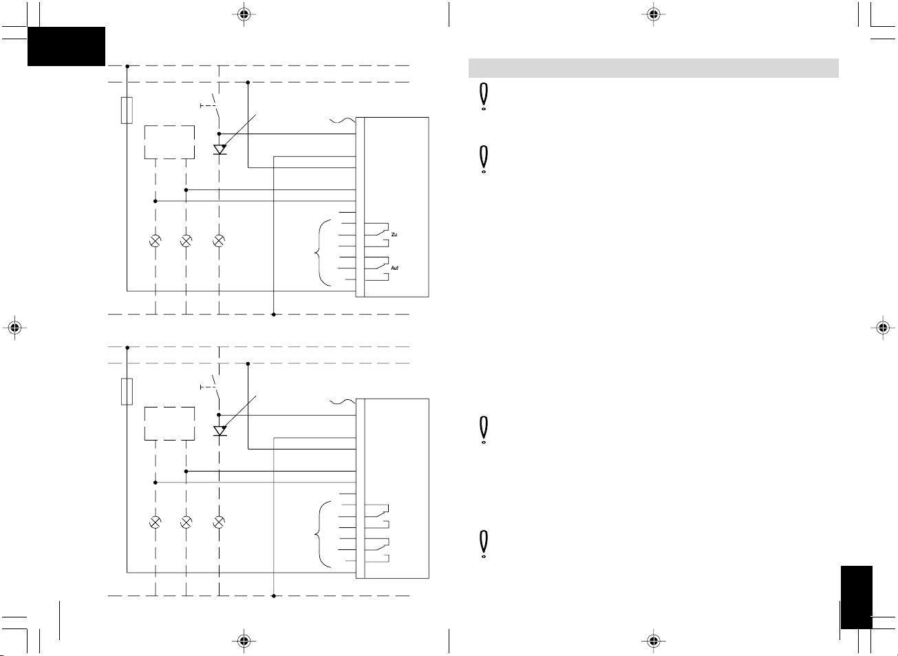
Blinker Relay
Close
Open
Note! If the dome light switched on when the door will
be unlocked by the key then a diode 1N4002 is
necessary
➃
Batterie +12 V
Kl. 30
Antenne
Türkontakt
+ (plus) geschaltet
Masse (-) Kl. 31
Zündung +12 V
KL. 15
Blinker links
Blinker rechts
Frei
2
3
4
5
6
7
1
8
9
10
11
12
13
14
15
16
Grün
Schwarz
Orange
Schwarz/weiß
Schwarz/grün
Rot
Zentralverriegelung
Schaltpläne
1 - 8
Blinker links
Blinker rechts
Klemme 30 (+ Batterie)
Klemme 15 (+ Zündung)
Klemme 31 (- Batterie)
Türkontaktschalter
Innenleuchte
Blinker Relais
Hinweis! Wird die Innenleuchte beim Öffnen des
Fahrzeuges mit dem Schlüssel eingeschaltet, muss eine
Diode 1N4002 (Siehe Schaltplan) eingesetzt werden
➃
J
191
FIN
Huomioi! Älä koskaan liitä molempia johtoja (vihreät ja keltaiset
johdot).
Eristä kaikki johdot, joita ei tarvita tai käytetä mihinkään.
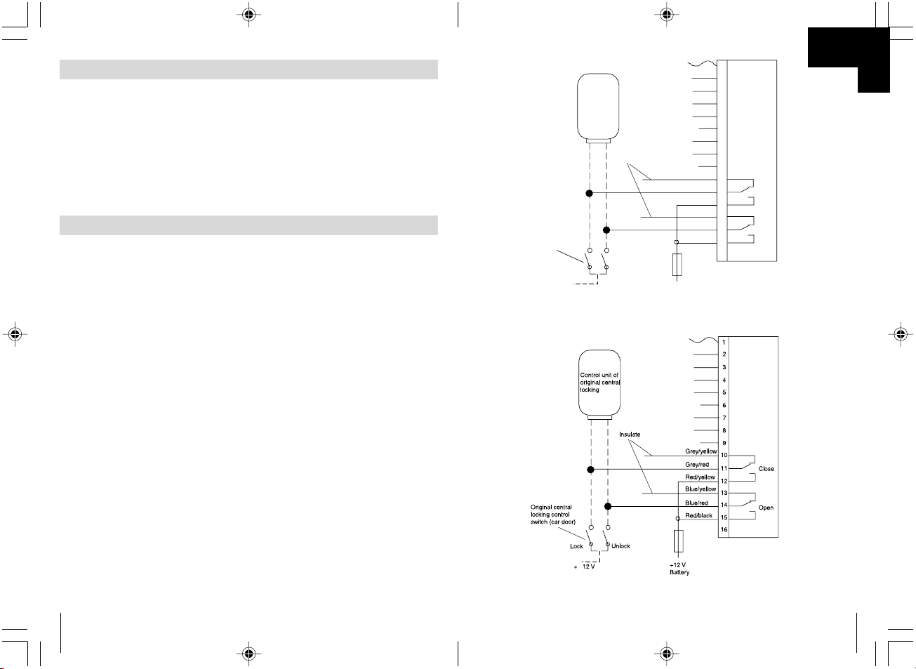
Kytkentäkaavio nro. 1 (katso ✎ K ➀)
Huomioi! Tämä kytkentäkaavio koskee vain ajoneuvoja ilman
moottoria kuljettajan ovessa ja alipainekeskuslukitusta ilman
sähköistä ohjausjohtolinjaa.
Kytkentäkaavio nro. 2, kaksi pääjohtoa, miinus ja plus, 12 volttia
(katso ✎ K ➁)
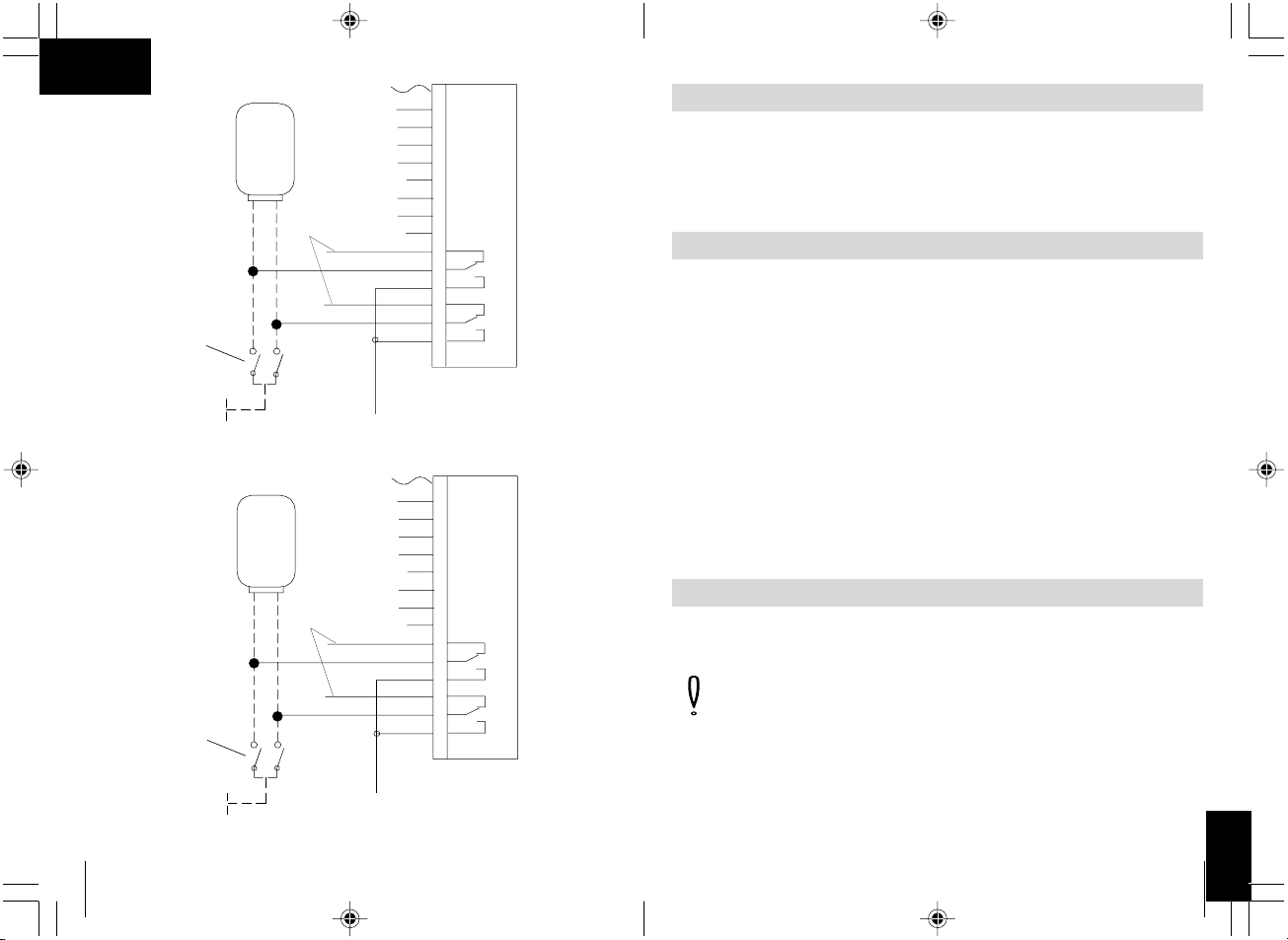
Kytkentäkaavio nro. 3, kaksi pääjohtoa +12 volttia, sykäyksellä
(katso ✎ K ➂)
Kytkentäkaavio nro. 4, kaksi pääjohtoa miinussykäyksellä
(katso ✎ K ➃)
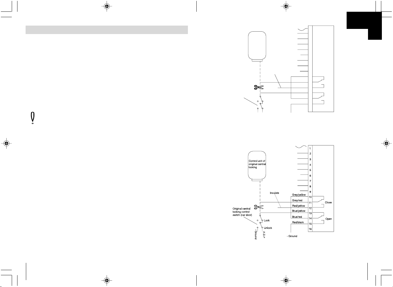
Kytkentäkaavio nro. 5, yksi johto, avoin miinussykäyksellä
(katso ✎ K ➄)
Kytkentäkaavio nro. 6, yksi johto +12 volttia miinussykäyksellä
(katso ✎ K ➅)
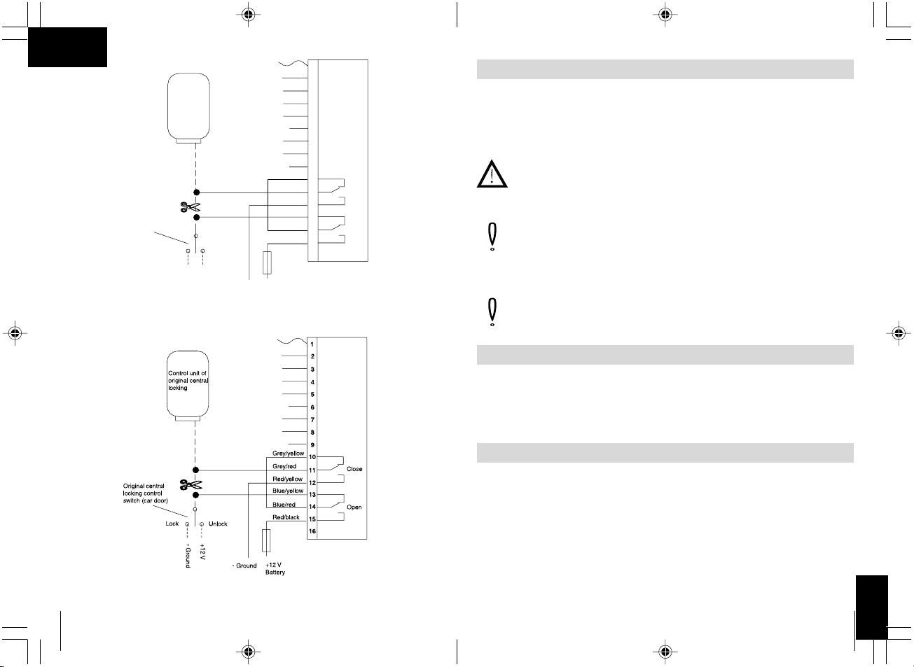
Kytkentäkaavio nro. 7, liitäntään WAECO keskuslukitukseen
ML-44(22) IR (katso ✎ K ➆)
Tärkeää! Tarkasta kauko-ohjauksella "suljettaessa", että vilkkuvalot
vilkkuvat yhden (1) kerran. Jos ne vilkkuvat kaksi kertaa, sininen/
punainen kaapeli on jälleenkytkettävä ohjauslaitteen mustaan
kaapeliin ja harmaa/punainen kaapeli ohjauslaitteen punaiseen
kaapeliin.
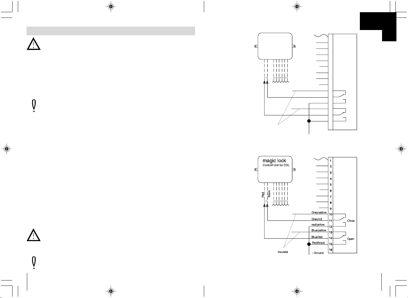
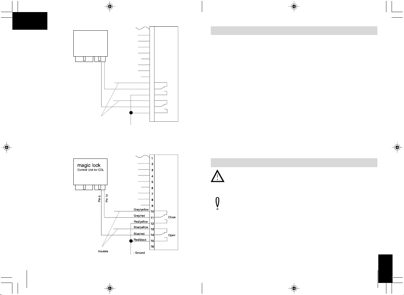
Kytkentäkaavio nro. 8, liitäntään WAECO keskuslukitukseen
ML-44(22) (katso ✎ K ➇)
Tärkeää! Tarkasta kauko-ohjauksella "suljettaessa", että vilkkuvalot
vilkkuvat yhden (1) kerran. Jos ne vilkkuvat kaksi kertaa, harmaa/
punainen kaapeli on jälleenkytkettävä ohjauslaitteen Pin 5:een ja
sininen/punainen kaapeli ohjauslaitteen Pin 10:een.
Keskuslukitukseen liittäminen
Page 11
190
Seuraavaksi on selvitettävä kaikkien muiden sähköisesti ohjattujen
keskuslukitusten toimintatapa. Tähän tarkoitukseen tulee, mikäli
mahdollista, käyttää valtuutetuilta merkkikorjaamoiolta saatavia
alkuperäisiä kytkentäkaavioita.
Jos alkuperäisiä kytkentäkaavioita ei ole käytettävissä, on selvitettävä
ohjausjohtolinjojen toiminto. Ohjausjohtolinjat kulkevat keskuslukituksen
ohjauslaitteelta ajoneuvon ovelle.
Huomioi! Liitäntä on muodostettava keskusohjauksen
ohjausjohtolinjoilla eikä muilla johdoilla. Muihin kuin
ohjausjohtolinjoihin johtoihin liittäminen tai väärän kytkentäkuvan
käyttäminen liitäntää muodostettaessa saattaa johtaa siihen, että
keskuslukitus ja kauko-ohjaus vahingoittuvat.
Tarkasta, miten ajoneuvosi keskuslukitus toimii.
Liitä keskuslukitus kytkentäkaavion mukaan (katso ✎ K ➀ – ➇).
Muutamien autojen kohdalla, esimerkiksi Mercedeksen, voi olla että
0,6 sekunnin ohjausaika ei ole riittävä keskuslukituksen kytkemiseksi.
Tälläisissa tapauksissa ohjausaika on asetettava 3,5 sekunniksi
DIP-katkaisijalla 1 (katso ✎ L ➀).
Tavallisesti valintakatkaisijan 1 asetus 0,6 sekunttia.
Automaattisen jälleensulkemisen liitäntä ovikoskettimeen soveltuu
ajoneuvoille miinus (-) kytketyillä ovikoskettimilla ja ajoneuvoille + 12 voltin
kytketyillä ovikoskettimilla.
Jos ovikosketin on miinus (-) kytketty keltainen johto liitetään
kytkentäjohtoon. Jos tätä toimintoa ei haluta käyttää keltainen johto on
maadoitettava.
Jos ovikosketin on kytketty + 12 volttiin vihreä johto liitetään
kytkentäjohtoon (katso ✎ J ➃). Jos ätä toimintoa ei haluta käyttää vihreää
johtoa ei tule liittää mihinkään vaan eristää.
Keskuslukitukseen liittäminen
11
Zu
Auf
Blau/gelb
Grau/gelb
Grau/rot
Rot/gelb
Grün
Blau/rot
Rot/schwarz
Blau
- Minus
Masse
+ 12 Volt
Batterie
2
3
4
5
6
7
1
8
9
10
11
12
14
15
16
13
2
3
4
5
6
7
1
8
9
10
11
12
14
15
16
13
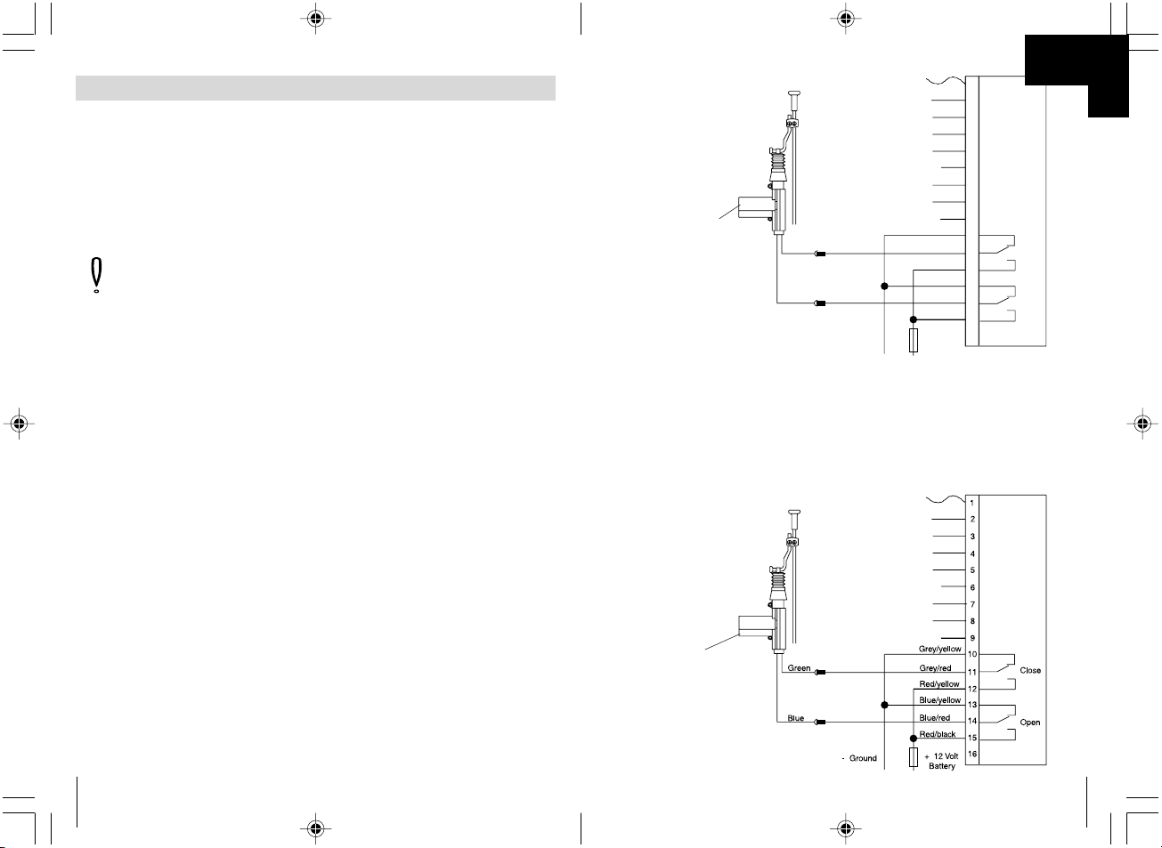
Zusätzlich benötigter
Stellmotor für Fahrertür
WAECO Art.-Nr. ML-11
Servo motor for
drivers's door
WAECO Art.-Nr. ML-11
➀
➀
K
✎
Page 12
12
2
3
4
5
6
7
1
8
9
10
11
12
14
15
16
13
Grau/gelb
Rot/gelb
Blau/gelb
Blau/rot
Rot/schwarz
Grau/rot
AufZuAuf
+12 V
Batterie
+ 12 Volt
- Masse
+ 12 Volt
- Masse
ZV-Motoren
Original
ZV-Steuergerät
AufZu
➁
➁
K
189
FIN
Huomioi! Oikosulkuvaaran takia akun miinusnapa on aina
irrotettava ennen kun ajoneuvon sähköisiä osia käsitellään. Jos
ajoneuvossa on ylimääräinen akku myös siitä on irrotettava
miinusnapa.
Liitä vastaanotin seuraavan liitäntäsuunnitelman (katso ✎ J ➀),
pistokkeiden sijoituskaavio (katso ✎ J ➁) ja kytkentäkaavion
(katso ✎ J ➂ + ➃) mukaan.
Ajoneuvon suunnannäyttölaitteeseen (vilkkuvalo) liitettäessä vilkkuvalot
vilkkuvat 1 tai 2 kertaa (mikäli lainmukaista).
Sijoituskaavio (katso ✎ J ➀)
Pistokkeiden sijoituskaavio (katso ✎ J ➁)
Kytkentäkaavio ovikosketin (-) miinus kytketty (katso ✎ J ➂)
Kytkentäkaavio ovikosketin (+) plus kytketty (katso ✎ J ➃)
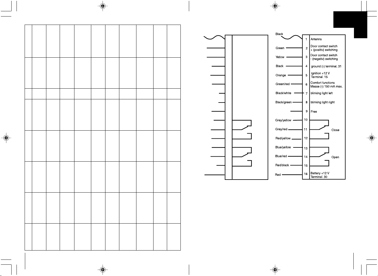
– Esimerkki 3: Kaapelin liittäminen maadoitukseen.
Poista kaapelista noin 5 mm eristettä (katso ✎ H ➀).
Käytä Ø 6 mm hammastettu kaapelikenkä liitoksella (katso ✎ H ➁).
Purista kaapelikenkä kiinni johtoon liitinpihdillä (katso ✎ H ➂).
Ruuvaa kaapelikenkä kiinni alkuperäiseen maadoituskohtaan
(katso ✎ H ➃).
– Esimerkki 4: Kaapelin varustaminen lattaliittimellä.
Poista kaapelista noin 5 mm eristettä (katso ✎ I ➀).
Käytä pistoke tarkoitukseen soveltuvalla liitoksella (esim. lattaliitinhylsy)
(katso ✎ I ➁).
Purista kaapelikenkä kiinni johtoon liitinpihdillä (katso ✎ I ➂).
Käytä tarvittaessa pistoliitintä eristyshylsyllä (katso ✎ I ➃).
Kaapelin sijoittaminen
Käytännössä kaikki keskuslukitukset ovat elektronisesti ohjattuja.
Jos ajoneuvon kuljettajan puoleisessa ovessa ei ole moottoria (nämä
ajoneuvot tunnistetaan siitä, että kuljettajan ovea ei voi lukita ja avata
toisilta ovilta), oveen on jälkikäteen asennettava moottori. Tähän
tarkoitukseen voidaan käyttää moottoria WAECO-tuotenro. ML-11.
Se liitetään kytkentäkaavion nro. 1 (katso ✎ K ➀) mukaan.
Keskuslukitukseen liittäminen
Radiovastaanottimen sähköinen liittäntä
Page 13
188
– Vastaanottimelta ja kaapelisarjalta on oltava riittävän pitkä etäisyys
ajoneuvon mekaanisiin, liikkuviin osiin, esimerkiksi ratinpylvääseen tai
jarru- ja kaasupolkimiin ja kytkimen polkimeen, jotta kaapeli tai
vastaanotin ei jäisi puristuksiin tai hankautuisi ja näin ollen vahingoittuisi.
– Jos radiovastaanotinta halutaan asentaa verhoilun taakse on
varmistettava, että verhoilua on mahdollista kiinnittää takaisin paikoilleen.
– Jos radiovastaanotinta kiinnitetään ruuveilla on varottava, etteivät muut
ajoneuvon osat eivät vahingoidu.
Radiovastaanottimen asentaminen
Jos kaapelia ei ole sijoitettu ja kaapeleita liitetty asianmukaisella tavalla
seurauksena on aina rakenneosien virheellinen toiminta ja niiden
vahingoittumiset. Asianmukainen kaapelin sijoittaminen ja/tai kaapeliliitos
on perusedellytys sille, että jälkikäteen asennetut osat toimivat pysyvästi
ja virheettömästi.
Noudata seuraavia kohtia:
– Vedä kaapelit niin, että ne eivät voi vahingoittua.
Älä sijoita kaapelia teräviä reunoja vastaan tai kuumien tai liikkuvien
ajoneuvon osien viereen.
– Sijoita kaapeli alkuperäisten kaapelien viereen ja yhdistä ne aina, mikäli
mahdollista, eristysnauhalla tai niputtajalla.
– Jos kaapelia halutaan vetää ajoneuvon sisätilasta moottori- tai
matkatavaratilaan on käytettävä väliseinissä jo olevia aukkoja.
– Kaapelia tulee kiinnittää vain tarkoitukseen soveltuvin menetelmin.
Seuraavassa neljä esimerkkiä.
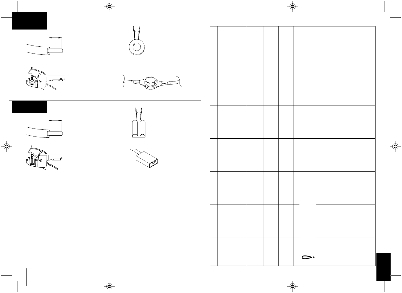
– Esimerkki 1: Kaapelin liittäminen alkuperäisiin osiin.
Poista eriste noin 10 mm alueelta alkuperäisestä johdosta (katso ✎ F ➀).
Poista eriste 15 mm alueelta liitettävästä kaapelista (katso ✎ F ➁).
Kierrä liitettävä johto alkuperäisen johdon ympärille ja juota johdot yhteen
(katso ✎ F ➂).
Eristä kaapeli eristysnauhalla (katso ✎ F ➃).
– Esimerkki 2: Kahden kaapelia liittäminen.
Poista eristeet molemmasta kaapelista (katso ✎ G ➀).
Työnnä toinen kaapeli noin 20 mm pituiseen kutisteletkuun (katso ✎ G ➁).
Kierrä kaapelit yhteen ja juota ne yhteen (katso ✎ G ➂).
Työnnä kutisteletku juotosliitoksen päälle ja lämmitä varovasti
(katso ✎ G ➃).
Kaapelin sijoittaminen
13
Steuergerät
der OriginalZentralverriegelung
Rot/gelb
Blau/gelb
Blau/rot
Rot/schwarz
Grau/gelb
Grau/rot
Zu
Auf
2
3
4
5
6
7
1
8
9
10
11
12
14
15
16
13
+12V
Original-Zentralverriegelungs-Steuerschalter (Fahrzeugtür)
Isolieren
+12 V
Batterie
AufZu
➂
➂
K
✎
Page 14
14
2
3
4
5
6
7
1
8
9
10
11
12
14
15
16
13
Rot/gelb
Blau/gelb
Blau/rot
Rot/schwarz
Grau/gelb
Grau/rot
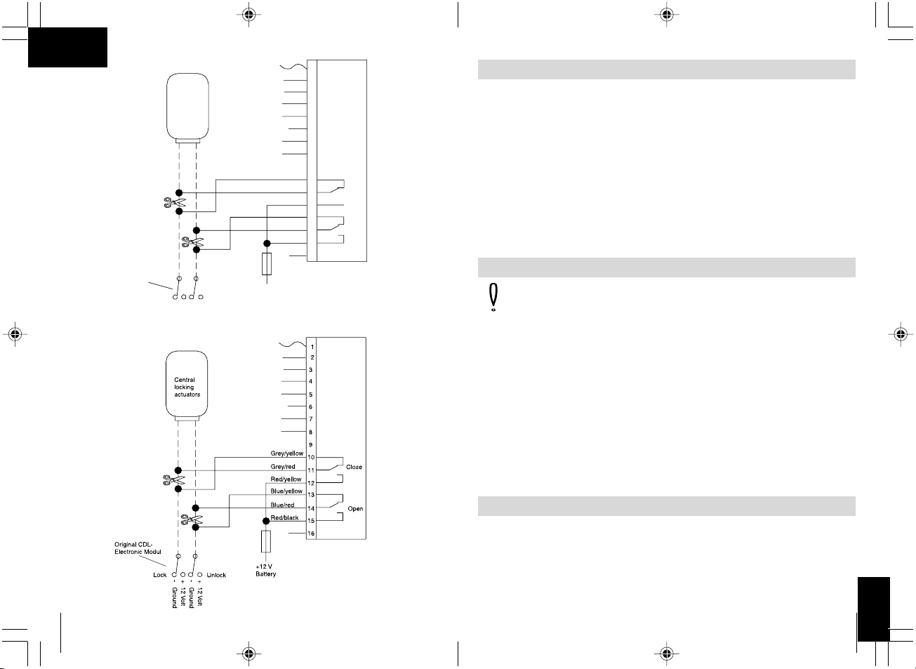
Original-Zentralverriegelungs-Steuerschalter (Fahrzeugtür)
- Minus
Masse
Isolieren
Zu
Auf
- Minus
Masse
Steuergerät
der OriginalZentralverriegelung
Zu Auf
2
3
4
5
6
7
1
8
9
10
11
12
14
15
16
13
- Ground
- Ground
Control unit of
original central
locking
Close
Open
Insulate
Grey/yellow
Grey/red
Red yellow/
Blue/yellow
Blue/red
Red black/
Original central
locking control
switch (car door)
Lock
Unlock
➃
➃
K
187
FIN
Toimittavat työkalut
Nro. Lukumäärä Nimitys Tuotenro.
(katso ✎ B ➀) 1 Radiovastaanotin Nro. MT-350RX
(katso ✎ B ➁) 2 Radiolähetin Nro. MT-650TX
(katso ✎ B ➂) 1 Vastaanottimen liitoskaapeli Nro. MT-350KA
Tarvittavat työkalut
Asennukseen tarvitaan:
– Mittasauva (katso ✎ C ➀) – Pora (katso ✎ C ➃)
– Merkkipuikko (katso ✎ C ➁) – Porakone (katso ✎ C ➄)
– Vasara (katso ✎ C ➂) – Ruuvimeisseli (katso ✎ C ➅)
Sähköiseen liitäntään ja valvontaan tarvitaan:
– Dioditestaus (katso ✎ D ➀) – Kutisteletku
tai jännitemittari (katso ✎ D ➁) – Kuumailmapuhallin (katso ✎ D ➃)
– Liitipihdit (katso ✎ D ➂) – Juottokolvit (katso ✎ D ➄)
– Eristysnauha – Juottotina (katso ✎ D ➅)
Vastaanottimen ja kaapelin kiinnittämiseen tarvitaan mahdollisesti lisäksi
ruuveja, peltiruuveja ja kaapeliliitintä.
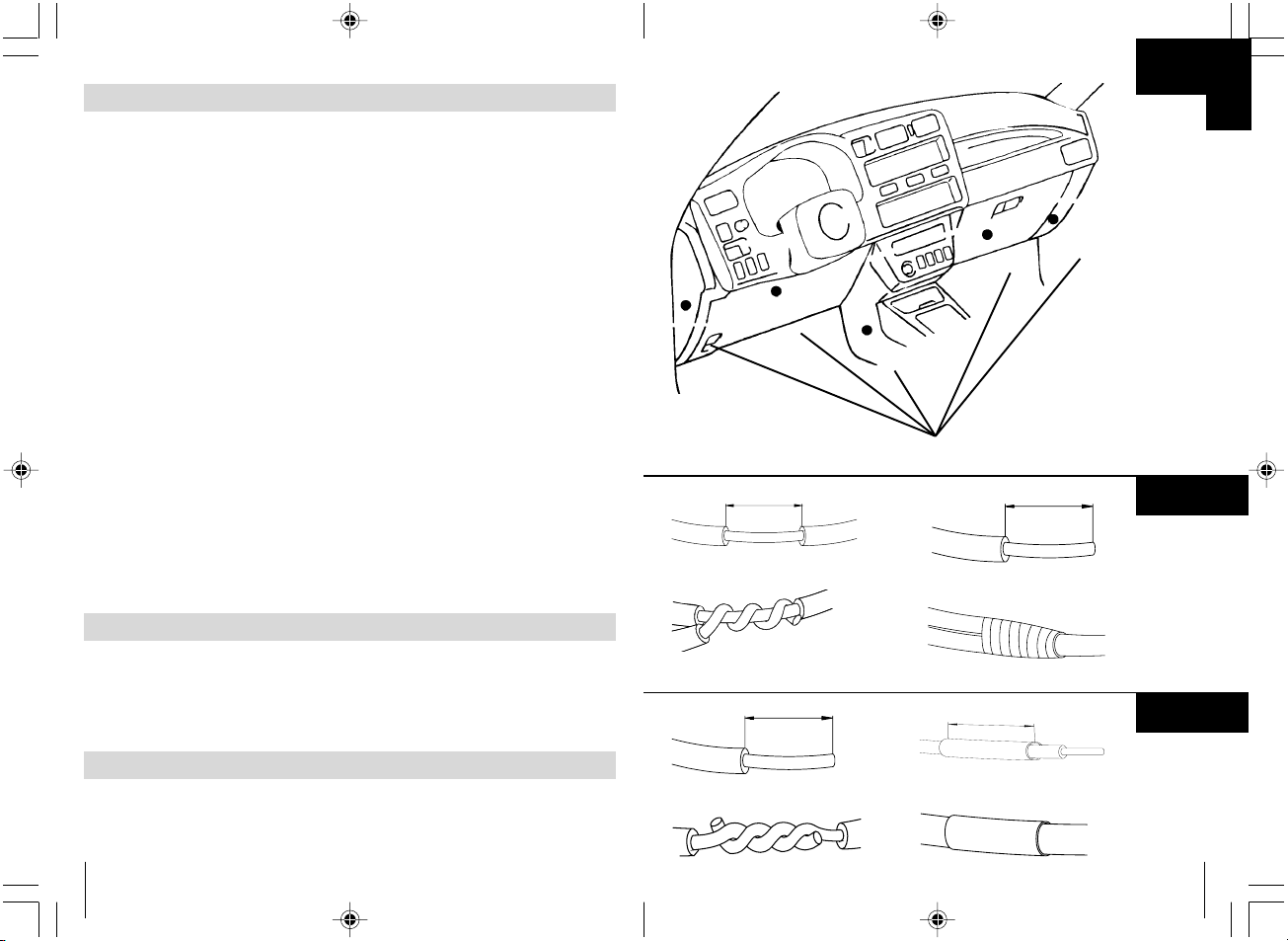
Valitse tarkoitukseen soveltuva paikka radiovastaanottimelle.
Soveltuvat asennuspaikat (katso ✎ E ➀) sijaitsevat kojelaudan alla,
keskikannattimen tai käsilokeron takana.
Valitse asennuspaikka seuraavia ohjeita noudattaen:
– Asenna radiovastaanotin siten, että siihen on helppo päästä käsiksi kun
käsilähetintä halutaan jälkiohjelmoida.
– Älä kiinnitä vastaanotinta muiden ohjauslaitteiden välittömään
läheisyyteen. Muuten molemmissa laitteissa esiintyy häiriöitä.
Seurauksena saattaa olla virhetoiminnot ja radiokauko-ohjauksen
ulottuvuus saattaa heikentyä.
Radiovastaanottimen asentaminen
Page 15
186
Radiokauko-ohjauksen toiminnot
Keskuslukituksen sulkeminen
Keskuslukitus lukitaan käsilähettimen vasempaa sinistä painikketta
painamalla. Tämän vahvistuksena vilkkuvalo vilkkuu yhden kerran.
Keskuslukituksen avaaminen
Keskuslukitus avataan kun käsilähettimen vasempaa sinistä painikketta
painetaan toisen kerran. Tämän vahvistuksena vilkkuvalo vilkkuu kaksi
kertaa.
Comfort-toiminto
Käsilähettimen oikeaa harmaata painiketta painamalla comfort-lähtö
kytkeytyy päälle (kun ajoneuvo on lukossa) ja ohjaa liitännästä riippuen
ikkunannostajan, hälytinjärjestelmän tai lämmistyksen.
Huomioi! Tämän comfort-toiminnon maksimivirta ei saa ylittää
150 mA. Suurempia moottoreita varten on käytettävä lisärele
(työvirtarele) vaapadiodilla.
Automaattinen jälleensulkeminen
Jos käsilähetintä painetaan vahingossa (keskuslukitus auki) ja ovea
ei avata keskuslukitus lukittuu jälleen noin yhden (1) minuutin kuluttua.
Jos tätä toimintoa ei haluta käyttää, keltainen ohjausjohto on liitettävä
maadoitukseen ja vihreä johto on eristettävä.
Varmuuslukitus
Sytytyksen ollessa päällä keskuslukitusta on mahdollista lukita
käsilähettimen avulla. Tällöin vilkkuvalot eivät kytkeydy päälle.
Keskuslukitusta voidaan avata käsilähettimellä tai sytytystä katkaisemalla.
Kaikki ajoneuvott eivät tue tätä toimintoa.
Sisätilan valaistus
Sisätilan valaistus kytkeytyy päälle kun keskuslukitusta avataan
radiokauko-ohjauksella ja sammuu kun sytytys kytketään päälle.
Tämän toiminto on käytössä kaikissa ajoneuvoissa, joissa on
miinuskytketyt (maadoitetut) ovikoskettimet.
15
2
3
4
5
6
7
1
8
9
10
11
12
14
15
16
13
Rot/gelb
Blau/gelb
Blau/rot
Rot/schwarz
Grau/gelb
Grau/rot
Steuergerät
der OriginalZentralverriegelung
- Minus
Masse
Isolieren
Original-Zentralverriegelungs-Steuerschalter (Fahrzeugtür)
Zu
Auf
+12 V
- Minus
Masse
Zu
Auf
➄
➄
K
✎
Page 16
16
2
3
4
5
6
7
1
8
9
10
11
12
14
15
16
13
2
3
4
5
6
7
1
8
9
10
11
12
14
15
16
13
+12 V
Batterie
Steuergerät
der OriginalZentralverriegelung
- Minus
Masse
Original-Zentralverriegelungs-Steuerschalter (Fahrzeugtür)
+12 V
- Minus
(Masse)
Zu
Auf
Rot/gelb
Blau/gelb
Blau/rot
Rot/schwarz
Grau/gelb
Grau/rot
Auf
Zu
➅
➅
K
185
FIN
Seuraavat tiedot on syötettävä uudestaan ajoneuvon varustetason
mukaan:
Radiokoodi · Ajoneuvon kello · Aikalaukaisin · Ajotietokone · Istuin
Asennusta koskevat ohjeet ja tiedot löytyvät käyttöoppaista.
Varoitus! Ajoneuvoon asennetun MAGIC TOUCH MT-350 osat on
kiinnittävä siten, että ne eivät missään tapauksessa (yhtäkkinen
jarruttaminen, liikenneonnettomuus) voi irrota ja näin aiheuttaa
loukkaantumisia.
Huomioi! Sähköisten johtojen jännitteen testaamiseen saa käyttää
ainostaan dioditestauslampua (katso ✎ A ➀) tai jännitemittaria
(katso ✎ A ➁). Tarkastuslamput valaisevalla kappaleella
(katso ✎ A ➂) käyttävät liikaa virtaa ja saattavat vahingoittaa
ajoneuvon elektroniikkaa.
Huomioi! Vahinkojen välttämiseksi porauksia varten on varattava
riittävästi vapaata tilaa (katso ✎ A ➃). Jokaista porausta on
siistittävä ja käsiteltävä ruosteenestoaineella .
Turvallisuus- ja asennusohjeet
Johdanto
MT-350 radiokauko-ohjaus on lisää ajoneuvonne keskuslukituksenne
käytettävyyttä. Yhdellä pienellä lähettimellä voidaan avata ja sulkea
ajoneuvon ovet. Lisämodullilla on mahdollista laajentaa toimintoja, kuten
esim. kytkeä sähköinen ikkunannostaja päälle, kytkeä kattoluukun
käyttökoneisto päälle tai kytkeä lämmitys päälle.
Kauko-ohjaimen yhden toiminnon edellytykset
Ajoneuvon käyttöjännitteen on oltava 12 voltin.
Ajoneuvo on oltava varustettu keskusjännityksellä.
Muutamat autonvalmistajat varustavat autoja säästöversiolla. Näiden
autojen kuljettajan ovessa ei ole moottoria, vaan ainoastaan sähköinen
kytkin. Nämä autot on varustettava moottorilla (esim. WAECO tuotenro.:
ML-11). Tarkista, onko ovessa moottori, seuraavalla tavalla:
– Lukitse ajoneuvo viereiseltä ovelta.
– Jos kuljettajan myös kuljettajan ovi on lukossa, ovessa on moottori.
– Jos kuljettajan ovi ei ole lukossa, kuljettajan oveen on asennettava
moottori jälkikäteen (esim. WAECO tuotenro.: ML-11).
Page 17
184
Turvallisuus- ja asennusohjeet
Varoitus! Huonot johtoliitokset saattavat johtaa oikosulkuihin,
jonka seurauksena puolestaan saattaa olla, että:
– kaapelit palavat
– airbag laukeaa
– sähkötoimiset ohjauslaitteet vahingoittuvat
– sähköiset toiminnot vahingoittuvat (vilkkuvalot, jarrutusvalot,
äänimerkiantolaite, sytytys, valot)
Tämän takia on noudatettava seuraavia ohjeita:
Johtoja käsitellessä:
30 (akun tulo, plus suora),
15 (kytketty plus, akun takana)
31 (paluujohto akulta, maadoitettu)
L (vilkkuvalot vasemmalla)
R (vilkkuvalot oikealla)
Varmin tapa suorittaa liitos on juottaa kaapelien päät kiinni toisiinsa ja
samalla eristää ne.
Jos liitokset ei haluta olevan pysyviä saa käyttää vain eristettyjä
kaapelikenkiä, pistokkeita ja lattapistokkeita. Älä käytä puristusliitintä
(johdonjatkostuslaite) tai muita liittimiä.
Kaapelin liittämiseen kaapelikengillä, pistokkeilla tai lattaliittimillä käytetään
liitinpihti.
Kaapelien liittäminen 31:een (maadoitus):
Ruuvaa kaapeli kiinni ajoneuvossa olevaan maadoitusruuviin
kaapelikenkää ja hammaskiekkoa käyttämällä tai ruuvaa kaapeli kiinni
autonkoriin kaapelikengällä, peltiruuvilla ja hammaskiekolla.
Pidä huolta, että maadoitus on riittävän hyvä!
Varoitus! Oikosulkuvaaran takia akun miinusnapa on aina
irrotettava ennen kun ajoneuvon sähköisiä osia käsitellään.
Jos ajoneuvossa on ylimääräinen akku myös siitä on
irrotettava minuusnapa.
Huomioi! Akun miinusnapaa irrotettaessa tallennetut tiedot
häviävät kaikista comfort-elektroniikan katkeavista muisteista.
17
➆
➆
2
3
4
5
6
7
1
8
9
10
11
12
14
15
16
13
2
3
4
5
6
7
1
8
9
10
11
12
14
15
16
13
Rot/gelb
Blau/gelb
Blau/rot
Schwarz
Grau/gelb
Grau/rot
Zu
Auf
Rot
Rot/schwarz
magic lock
SteuergerätfürZV
Isolieren
- Minus
Masse
K
✎
Page 18
18
➇
➇
- Minus
Masse
2
3
4
5
6
7
1
8
9
10
11
12
14
15
16
13
2
3
4
5
6
7
1
8
9
10
11
12
14
15
16
13
Zu
Auf
Rot/gelb
Blau/gelb
Blau/rot
Grau/gelb
Grau/rot
Rot/schwarz
magic lock
SteuergerätfürZV
Pin 5
Pin 10
Isolieren
K
183
FIN
Varoitus! Turvallisuusohje:
Laiminlyönti saattaa johtaa henkilövahinkoihin tai aineellisiin
vahinkoihin.
Huomioi! turvallisuusohje:
Laiminlyönti johtaa aineellisiin vahinkoihin ja vaikuttaa
MAGIC TOUCH MT-350:n toimintoon.
Rombi merkitsee asennuksia, joita Sinun on suoritettava.
Jotta asennusta olisi mahdollista suorittaa vaikeuksitta,
tämä asennus- ja käyttöopas on luettava ennen asennuksen
aloittamista.
Jos MAGIC TOUCH MT-350 siirtyy toiselle omistajalle myös
asennus- ja käyttöopas on luovutettava uudelle omistajalle.
Käyttöoppaan käyttöä koskevat ohjeet
Otsikko Sivu
Asennusoppaan kuvaukset 3-19
Sisältö 183
Asennusoppaan käyttöohjeet 183
Turvallisuus- ja asennusohjeet 184-185
Johdanto 185
Kauko-ohjaimen yhden toiminnon edellytykset 185
Kauko-ohjaimen toiminnot 186
Toimituksen sisältö 187
Tarvittavat työkalut 187
Radiovastaanottimen asentaminen 187-188
Kaapelin sijoittaminen 188-189
Radiovastaanottimen sähköinen liittäntä 189
Keskuslukitukseen liittäminen 189-191
Ajoneuvokohtaiset ohjeet 192-195
Radiovastaanottimen asetukset 196
Käsilähettimien kuittaaminen 196
Käsilähettiminen jälkikoodaus 196-197
Käyttöopas 197-198
Pariston vaihtaminen 198
Tekniset tiedot 199
Sisällysluettelo
Page 19
182
19
➀
➁
Schalter 1
SWITCH 1
Schalter 2
SWITCH 2
L
✎
Page 20
20
181
N
Driftsspenning: 9 - 16 V DC
Hvilestrømopptak: 5 mA
Maks. strømopptak: 16 A kort tid
Driftstemperatur: -40 til +85 °C mottaker
-20 til +60 °C sender
Sendefrekvens: 433,92 MHz
Rekkevidde: 10 m ... 20 m
Koblingsstrøm sentrallås: maks. 10 A
Koblingsstrøm blinklysaktivering: maks. 2 x 5 A
Koblingsstrøm ekstrautgang: maks. 150 mA
Sentrallåsstyretid: etter valg 0,6/3,5 sek.
Blinklysstyretid: 1 x 0,75 sek. / 2 x 0,75 sek./
På /Av
Mål håndsender (L x B x H): 52 x 35 x 13 mm
Mål mottaker (L x B x H): 97 x 140 x 32 mm
Tekniske data
Page 21
180
Rekkevidden er alt etter montering av mottakeren og utgangseffekten fra
støykilder i omgivelsene opptil 20 m.
Håndsenderen sender en ny kode ved hver betjening (vekselkode). Hvis
håndsenderen blir betjent for ofte uten at mottakeren mottar sendesignalet,
kan det hende at mottakeren ikke gjenkjenner senderen med en gang. Du
må da betjene håndsenderen 1-2 ganger til. Senest den tredje gangen
gjenkjenner mottakeren senderen igjen.
Betjeningsanvisning
Hvis håndsenderens rekkevidde blir merkbart dårligere eller hvis kontrollLED flakker når den sender, må du skifte batteriet.
Bruk kun batterier som er lekkasjesikre og som er egnet for elektroniske
apparater. Oppbevar batteriene utilgjengelig for barn. Forsøk aldri å lade opp
batteriene igjen, de må aldri åpnes eller kastes på ild.
Beskytt miljøet! Brukte batterier skal ikke kastes i husholdningsavfallet, de
blir samlet i offentlige samlebeholdere eller hos fagforhandlere og deponert
på riktig måte.
Skru ut skruen på undersiden av håndsenderen og åpne senderen. Skift ut
batteriet. Pass på at polene ligger riktig når du legger inn batteriet (batteritype
CR 2032 3 Volt). Plusspolen er opp. Du får batterier f.eks. hos
fotoforhandlere, urmakere osv.
Sett lokket på håndsenderen igjen og skru inn skruen.
Skifte batteri
21
D
Warnung! Sicherheitshinweis:
Nichtbeachtung kann zu Personen- oder Materialschäden führen.
Achtung! Sicherheitshinweis:
Nichtbeachtung führt zu Materialschäden und beeinträchtigt die
Funktion der MAGIC TOUCH MT-350.
Die Raute kennzeichnet Einbauschritte, die Sie ausführen müssen.
Damit der Einbau ohne Schwierigkeiten stattfindet, diese Montageund Bedienungsanleitung vor Beginn der Montage durchlesen.
Bei einem Besitzwechsel von MAGIC TOUCH MT-350 muss diese
Montage- und Bedienungsanleitung mit übergeben werden.
Hinweise zur Benutzung der Einbauanleitung
Titel Seite
Abbildungen zur Einbauanleitung 3-19
Inhaltsangaben 21
Hinweise zur Benutzung der Einbauanleitung 21
Sicherheits- und Einbauhinweise 22-23
Einleitung 23
Voraussetzungen für eine Funktion der Funkfernbedienung 23
Funktionen der Funkfernbedienung 24
Lieferumfang 25
Benötigtes Werkzeug 25
Montage des Funk-Empfangsteils 25-26
Kabelverlegung 26-27
Elektrischer Anschluss des Funk-Empfangsteils 27
Anschluss an die Zentralverriegelung 27-29
Fahrzeugspezifische Hinweise 30-33
Schaltereinstellungen am Funk-Empfangsteil 34
Löschen von Handsendern 34
Nachcodieren von Handsendern 34-35
Bedienungsanleitung 35-36
Batteriewechsel 36
Technische Daten 37
Inhaltsverzeichnis
Page 22
22
Sicherheit- und Einbauhinweise
Warnung! Unzureichende Leitungsverbindungen können zur Folge
haben, dass durch Kurzschluss:
– Kabelbrände entstehen
– der Airbag ausgelöst wird
– elektronische Steuerungseinrichtungen beschädigt werden
– elektrische Funktionen (Blinker, Bremslicht, Hupe, Zündung, Licht)
ausfallen
Beachten Sie deshalb folgende Hinweise:
Bei Arbeiten an den Leitungen:
30 (Eingang von Batterie Plus direkt),
15 (Geschaltetes Plus, hinter Batterie)
31 (Rückleitung ab Batterie, Masse)
L (Blinkerleuchten Links)
R (Blinkerleuchten Rechts)
Die sicherste Verbindungsart ist, die Kabelenden miteinander zu verlöten
und anschließend zu isolieren.
Bei wiederlösbaren Verbindungen nur isolierte Kabelschuhe, Stecker und
Flachsteckhülsen verwenden. Keine Quetschverbinder (Leitungsverbinder)
oder Lüsterklemmen verwenden.
Zum Verbinden der Kabel mit Kabelschuhen, Stecker oder Flachsteckhülsen eine Krimpzange verwenden.
Bei Kabelanschlüssen an 31 (Masse):
Das Kabel mit Kabelschuh und Zahnscheibe an eine fahrzeugeigene
Masseschraube schrauben oder mit Kabelschuh, Blechschraube und
Zahnscheibe an das Karosserieblech schrauben.
Auf gute Masseübertragung achten!
Warnung! Wegen Kurzschlussgefahr vor Arbeiten an der Fahrzeugelektrik immer den Minuspol der Batterie abklemmen. Bei Fahrzeugen mit Zusatzbatterie ebenfalls den Minuspol abklemmen.
Achtung! Beim Abklemmen des Minuspols der Batterie verlieren
alle flüchtigen Speicher der Komfort-Elektronik ihre gespeicherten
Daten.
179
N
Skritt 1: Slå på tenningen.
Skritt 2: Betjen nå innen 10 sekunder begge tastene på en aktiv
funksjonsdyktig håndsender. Anlegget er nå i kodemodus. Som
bekreftelse blir bilen låst.
Skritt 3: Trykk på den blå tasten på den nye håndsenderen
til sentrallåsen blir åpnet som bekreftelse på den nye koden.
Skritt 4: Test den nye håndsenderen. Hvis den nye håndsenderen
ikke funksjonerer, må du gjenta de to forrige skrittene.
Låse sentrallåsen opp og igjen
Bilen låses opp og igjen med den blå tasten på håndsenderen. Når bilen
åpnes bekreftes dette med at blinklysene blinker to ganger. Når bilen låses
blinker blinklysene en gang.
Etter at bilen er låst opp blir kupélyset slått på og deretter slått av igjen etter
at tenningen er koblet inn eller etter 30 sekunder (kun for negativt koblete
dørkontakter).
Koble komfortfunksjoner
Utgangen for komfortfunksjoner kobles inn med den grå tasten (kun når bilen
er låst). Alt etter hvordan mottakeren er innstilt blir utgangen koblet i 10 sek.
eller koblet til en sendertast blir trykket. Innkobling av komfortfunksjon blir
bekreftet ved at blinklyset blinker en gang.
OBS! Den maksimale utgangsstrømmen (minus koblet) for denne
komfortfunksjonen må ikke overskride 150 mA. Når større forbrukere
blir aktivert må det settes inn et ekstra relé (MT-RELAY)
.
OBS - klemfare! La aldri vindusløftere lukke uten tilsyn.
For at fjernkontrollen skal funksjonere feilfritt er det nødvendig at
forbindelsen mellom sender og mottaker er uten forstyrrelser.
Betjeningsanvisning
Etterkoding av håndsendere
Page 23
178
Slette håndsendere
Håndsendere kan utelukkes fra bruk med fjernkontrollen (f. eks. hvis du
har mistet en håndsender) ved at du koder de håndsenderne som skal
være funksjonsberettiget 5 x etter hverandre. Følg fremgangsmåten som
beskrevet i det følgende avsnittet "Etterkoding av håndsendere".
Åpne bilen med håndsenderen
Sett deg inn i bilen. Alle dørene skal være lukket, men ikke låst.
Etterkoding av håndsendere
Innstillinger på mottakerdelen
Henvisning! For at innstillingene skal kunne gjenkjennes av
mottakerdelen, må tilkoblingsstøpslet trekkes ut først.
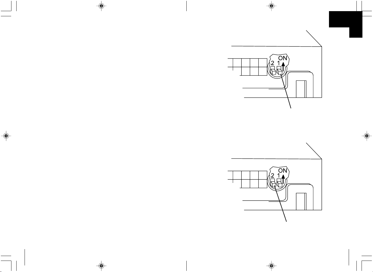
DIP bryter 1 (se ✎ L ➀)
Med denne bryteren blir styretiden for reléet for aktivering av sentrallåsen
innstilt.
Stilling On "3,5 sek."
Original SL blir aktivert i 3,5 sek.
Denne stillingen er nødvendig for noen originale sentrallåser som arbeider
pneumatisk og derfor trenger mer enn 0,6 sek. for lukkeprosessen.
Stilling Off "0,6 sek."
Denne stilingen er for alle elektriske sentrallåser som normalt trenger mindre
enn 0,6 sek. for lukkeprosessen.
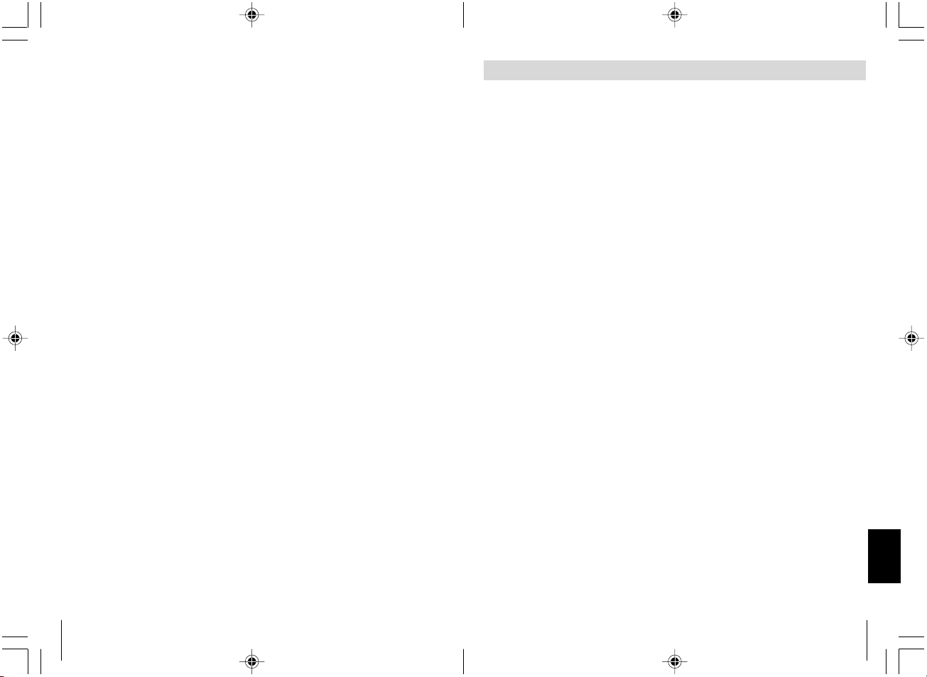
DIP bryter 2 (se ✎ L ➁)
Med denne bryteren blir styrefunksjonen for komfortkoblingen innstilt.
Stilling On
Utgang aktiv etter at den grå tasten er betjent. Er deaktivert når du trykker
en sendetast en gang til.
Stilling Off
Utgangen forblir aktiv i 10 sek. etter at den grå tasten er betjent.
23
D
Folgende Daten müssen Sie je nach Fahrzeugausstattung neu eingeben:
Radiocode · Fahrzeuguhr · Zeitschaltuhr · Bordcomputer · Sitzposition
Hinweise zur Einstellung können Sie in der jeweiligen Bedienungsanleitung
nachlesen.
Warnung! Im Fahrzeug montierte Teile der MAGIC TOUCH MT-350
müssen so befestigt werden, dass sie sich unter keinen Umständen
(scharfes Abbremsen, Verkehrsunfall) lösen können und zu Ver-
letzungen der Fahrzeuginsassen führen können.
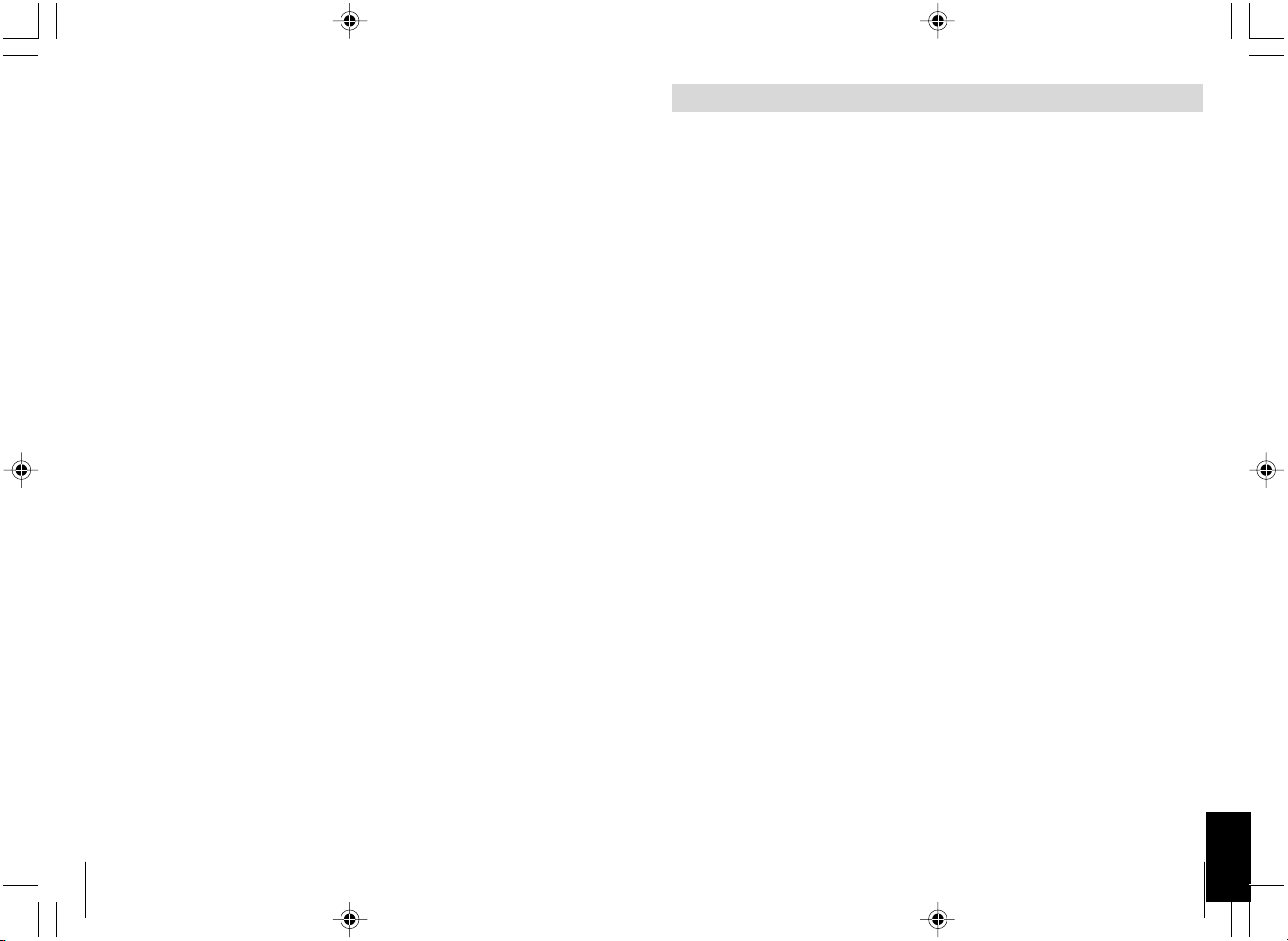
Achtung! Zum Prüfen der Spannung in elektrischen Leitungen
darf nur eine Diodenprüflampe (siehe ✎ A ➀) oder ein Voltmeter
(siehe ✎ A ➁) benutzt werden. Prüflampen (siehe ✎ A ➂) mit einem
Leuchtkörper nehmen zu hohe Ströme auf und die Fahrzeugelektronik kann beschädigt werden.
Achtung! Um Schäden zu vermeiden, auf ausreichenden Freiraum
für den Bohreraustritt (siehe ✎ A ➃) achten. Jede Bohrung entgraten und mit Rostschutzmittel behandeln.
Sicherheit- und Einbauhinweise
Einleitung
Die MT-350 Funk-Fernbedienung ist eine Ergänzung zu der Zentralverriegelung ihres Kraftfahrzeuges. Mit einem kleinen Sender öffnen und
schließen Sie die Türen Ihres Kraftfahrzeuges. Funktionserweiterungen,
wie z. B. die Aktivierung der elektrischen Fensterheber, des Schiebedachantriebs, oder der Standheizung sind über Zusatzmodule möglich.
Vorraussetzungen für eine Funktion der Fernbedienung
Ihr Fahrzeug muss eine Betriebsspannung von 12 V haben.
Ihr Fahrzeug muss mit einer Zentralverriegelung ausgestattet sein.
Einige Hersteller rüsten ihre Fahrzeuge mit einer Spar-Zentralverriegelung
aus. In diesen Fahrzeugen befindet sich in der Fahrertür kein Stellmotor,
sondern nur ein elektrischer Schalter. Bei diesen Fahrzeugen muss ein
Stellmotor nachgerüstet werden (z.B. WAECO Art. Nr.: ML-11). Um festzustellen ob ein Stellmotor vorhanden ist, gehen Sie wie folgt vor:
– Verschließen Sie Ihr Fahrzeug von der Beifahrerseite aus.
– Ist die Fahrertür verschlossen, ist ein Stellmotor vorhanden.
– Ist die Fahrertür nicht verschlossen, muss ein Stellmotor in der Fahrertür
nachgerüste werden (z.B. WAECO Art. Nr.: ML-11).
Page 24
24
Funktionen der Funkfernbedienung
Schließen der Zentralverriegelung
Durch Betätigen der linken blauen Taste des Handsenders wird die Zentralverriegelung geschlossen. Dies wird durch 1x Blinken der Blinker bestätigt.
Öffnen der Zentralverriegelung
Durch nochmaliges Betätigen der linken blauen Taste des Handsenders
wird die Zentralverriegelung geöffnet. Dies wird durch 2x Blinken der Blinker
bestätigt.
Komfortfunktion
Durch Betätigen der rechten grauen Taste des Handsenders wird der
Komfortausgang aktiviert (bei verriegeltem Fahrzeug) und steuert je nach
Anschluss die Fensterheber, eine Alarmanlage oder eine Standheizung.
Achtung! Der maximale Strom für diese Komfortfunktion darf
150 mA nicht übersteigen. Bei Ansteuerung von größeren Verbrauchern muss ein Zusatzrelais (Arbeitsstromrelais) mit einer
Freilaufdiode eingesetzt werden.
Automatisches Wiederverschließen
Wird der Handsender aus Versehen betätigt (Zentralverriegelung öffnet)
und es wird keine Tür geöffnet, wird die Zentralverriegelung nach ca. einer
Minute wieder geschlossen. Sollte diese Funktion nicht gewünscht sein,
muss die gelbe Steuerleitung an Masse angeschlosssen werden und die
grüne Leitung muss isoliert werden.
Sicherheitsverriegelung
Die Zentralverriegelung kann bei eingeschalteter Zündung über den Handsender geschlossen werden. Hierbei werden die Blinker nicht angesteuert.
Die Zentralverriegelung läßt sich über den Handsender oder durch Ausschalten der Zündung wieder öffnen. Diese Funktion wird nicht von allen
Fahrzeugtypen unterstützt.
Innenraumlicht
Das Innenraumlicht wird beim Öffnen der Zentralverriegelung mit der
Funkfernbedienung eingeschaltet und erlischt mit dem Ein-schalten der
Zündung.
Diese Funktion ist bei Fahrzeugen mit negativ (Masse) geschalteten
Türkontakten aktiv.
177
N
VW Passat 3B,
modell: 9/97-
VW Polo 6N,
modell: 95-
VW Sharan 7M,
modell: 96-
VW T4 modell: 93-
Blinklys venstre,
kabelfarge, posisjon
sort/hvit, kabel-streng
venstre på terskel
sort/hvit, kabel-streng
venstre på terskel
sort/hvit, kabel-streng,
venstre på terskel
sort/hvit, kabel-streng
venstre på terskel
Blinklys høyre,
kabelfarge, posisjon
SL åpen
kabelfarge, posisjon
SL lukket
kabelfarge, posisjon
Koblings-
skjema
Dørkontakt
kabelfarge, posisjon
sort/grønn, kabel-streng
venstre på terskel
sort/grønn, kabel-streng
venstre på terskel
sort/grønn, kabel-streng
venstre på terskel
sort/grønn, kabel-streng
venstre på terskel
rød/blå / pin 4 fra orig. SL
- styreapparat
grå/sort, A-søyle
venstre, fra førerdøren
grønn, A-søyle venstre,
fra førerdøren
gul, A-søyle venstre, fra
førerdøren
brun/blå, pin 2 fra orig. SL
- styreapparat
grå/rød, A-søyle
venstre, fra førerdøren
grå, A-søyle venstre, fra
førerdøren
hvit, A-søyle venstre,
fra førerdøren
Nr. 4
Nr. 3
Nr. 3
Nr. 3
brun/hvit, i
kabelgjennomføringen
på A-søyle, dørkontakt
er minuskoblet
brun/hvit, på dørkontakt
foran til venstre på
A-søyle, dørkontakt er
minuskoblet
brun/hvit, i
kabelgjennomføringen
på A-søyle, dørkontakt
er minuskoblet
brun/hvit, bak
sikringsboksen,
dørkontakt er
minuskoblet
Polariteten må kontrolleres før tilkobling.
Endringer forbeholdes.
Andre biler mulig på etterspørsel.
Anmerkning
Sentrallås er jordet styrt.
Det må settes inn en
200W motstand i den blå/
røde ledningen, SL-
styreapparat er i en sort
boks under teppet i
gulvet foran førersetet
Page 25
176
Opel Corsa A, B
modell: 93-2000
Opel Kadett E,
modell: 90-
Opel Omega A og B,
modell: 90-
Opel Vectra A og B
VW Golf lll og Vento
type 1HXO,
modell: 91-
VW Golf lV modell:
97- med elektriske
vindusløftere
VW Golf lV modell:
97- uten elektriske
vindusløftere
VW Lupo
modell: 98-
VW Passat 35i,
modell: 88-92
VW Passat 35i,
modell: 93-96
Blinklys venstre,
kabelfarge, posisjon
sort/hvit, kabelstreng
venstre på terskel
sort/hvit, kabelstreng
venstre på terskel
sort/hvit, kabelstreng
venstre på terskel
sort/hvit, kabelstreng
venstre på terskel
sort/hvit, kabelstreng
venstre på terskel
sort/hvit, kabelstreng
venstre på terskel
sort/hvit, kabelstreng
venstre på terskel
sort/hvit, kabelstreng
venstre på terskel
sort/hvit, kabelstreng
venstre på terskel
sort/hvit, kabelstreng
venstre på terskel
Blinklys høyre,
kabelfarge, posisjon
SL åpen
kabelfarge, posisjon
SL lukket
kabelfarge, posisjon
Koblings-
skjema
Dørkontakt
kabelfarge, posisjon
Anmerkning
grønn/sort, kabelstreng
venstre på terskel
grønn/sort, kabelstreng
venstre på terskel
grønn/sort, kabelstreng
venstre på terskel
grønn/sort, kabelstreng
venstre på terskel
sort/grønn, kabelstreng
venstre på terskel
sort/grønn, kabelstreng
venstre på terskel
sort/grønn, kabelstreng
venstre på terskel
sort/grønn, kabelstreng
venstre på terskel
sort/grønn, kabelstreng
venstre på terskel
sort/grønn, kabelstreng
venstre på terskel
brun/hvit / A-søyle
venstre, fra førerdøren
brun/hvit, A-søyle
venstre, fra førerdøren
brun/hvit, A-søyle
venstre, fra førerdøren
brun/hvit, A-søyle
venstre, fra førerdøren
grønn, A-søyle venstre,
fra førerdøren
gul/grønn pin 24, på
dør-styreapparat,
førerside
gul/grønn, SL-
styreapparat grått
støpsel 24 pol. under
dashbordet
blå/fiolett, A-søyle
venstre, fra førerdøren
sort/hvit, A-søyle
venstre, fra førerdøren
grønn, A-søyle venstre,
fra førerdøren
brun/rød / A-søyle
venstre, fra førerdøren
brun/rød, A-søyle
venstre, fra førerdøren
brun/rød, A-søyle
venstre, fra førerdøren
brun/rød / A-søyle
venstre, fra førerdøren
grå, A-søyle venstre, fra
førerdøren
gul/blå pin 4, på dør-
styreapparat, førerside
gul/blå eller blå, SL-
styreapparat grått
støpsel 24 pol. under
dashbordet
grå/gul, A-søyle
venstre, fra førerdøren
rot/gul, A-søyle venstre,
fra førerdøren
grå, A-søyle venstre, fra
førerdøren
Nr. 4
Nr. 4
Nr. 4
Nr. 4
Nr. 3
Nr. 4
Nr. 4
Nr. 4
Nr. 3
Nr. 3
grå, på dørkontakt foran
venstre på A-søyle,
dørkontakt er minus
koblet
grønn, på dørkontakt
foran venstre på A-
søyle, dørkontakt er
minus koblet
grå, på dørkontakt foran
venstre på A-søyle,
dørkontakt er minus
koblet
grå/hvit eller brun/hvit,
på dørkontakt foran
venstre på A-søyle,
dørkontakt er minus
koblet
brun/hvit, på dørkontakt
foran venstre på A-
søyle, dørkontakt er
minus koblet
brun/hvit, på dørkontakt
foran venstre på A-
søyle, dørkontakt er
minus koblet
blå/grå, på SL-
styreapparat på pin 18,
dørkontakt er minus
koblet
brun/hvit, i
kabelgjennomføring på
A-søyle, dørkontakt er
minus koblet
brun/hvit, på dørkontakt
foran venstre på A-
søyle, dørkontakt er
minus koblet
brun/hvit, på dørkontakt
foran venstre på A-
søyle, dørkontakt er
minus koblet
Dørstyreapparatet
befinner seg på
vindusløfteren under
dørkledningen
SL-styreapparatet er til
venstre ved siden av
rattstammen.
Kabelfargene finner man
også i A-søylen
25
D
Lieferumfang
Nr. Menge Bezeichnung Artikel-Nr.
(siehe ✎ B ➀) 1 Funk-Empfangsteil Art. Nr. MT-350RX
(siehe ✎ B ➁) 2 Funk-Handsender Art. Nr. MT-650TX
(siehe ✎ B ) 1 Anschlusskabel Empfangsteil Art. Nr. MT-350KA
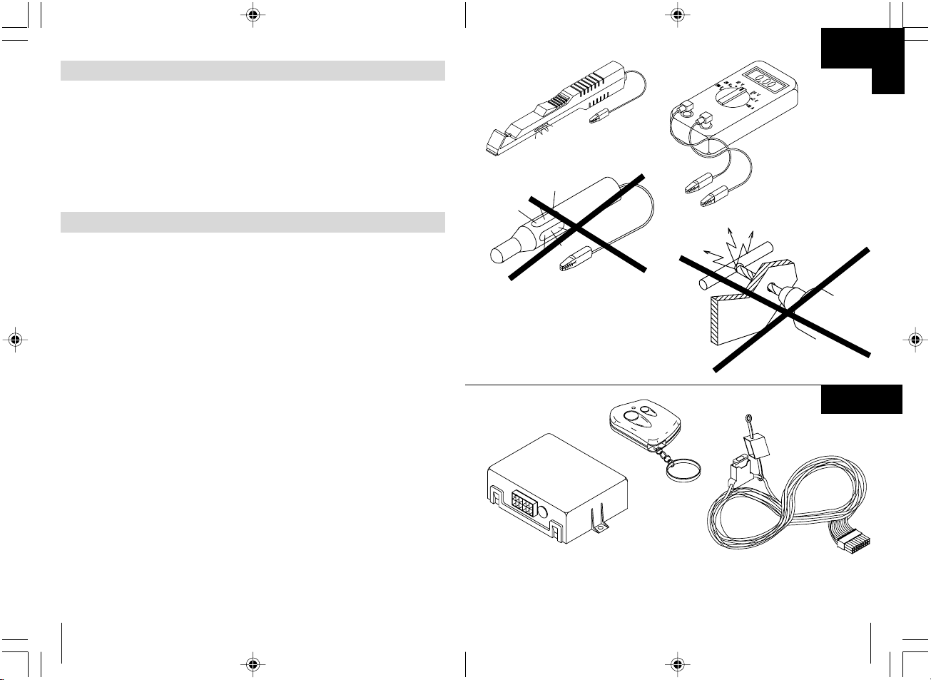
Benötigtes Werkzeug
Für Einbau und Montage werden benötigt:
– Maßstab (siehe ✎ C ➀) – Bohrer (siehe ✎ C ➃)
– Körner (siehe ✎ C ➁) – Bohrmaschine (siehe ✎ C ➄)
– Hammer (siehe ✎ C ➂) – Schraubendreher (siehe ✎ C ➅)
Für den elektrischen Anschluss und Überprüfung wird benötigt:
– Diodenprüflampe (siehe ✎ D ➀) – Wärmeschrumpfschlauch
oder Voltmeter (siehe ✎ D ➁) – Heißluftföhn (siehe ✎ D ➃)
– Krimpzange (siehe ✎ D ➂) – Lötkolben (siehe ✎ D ➄)
– Isolierband – Lötzinn (siehe ✎ D ➅)
Zur Befestigung von Empfänger und Kabel benötigen Sie evtl. noch
Schrauben, Blechschrauben und Kabelbinder.
Suchen Sie einen geeigneten Montageort für das Funk-Empfangsteil. Geeignete Montageorte (siehe ✎ E ➀) finden sich unter dem
Armaturenbrett, hinter der Mittelkonsole oder hinter dem Handschuhfach.
Beachten Sie folgende Hinweise zur Auswahl des Montageortes:
– Montieren Sie den Funk-Empfänger so, dass er leicht zugänglich ist, um
das Nachprogrammieren von Handsendern zu ermöglichen.
– Befestigen Sie den Empfänger nicht direkt neben anderen Steuergeräten.
Dieses führt zu gegenseitigen Störungen bei den Geräten. Es kann zu
Fehlfunktionen und zur Verminderung der Reichweite der Funk-Fernbedienung kommen.
Montage des Funk-Empfangsteils
Page 26
26
– Achten Sie auf einen ausreichenden Abstand von Empfänger und
Kabelsatz zu mechanisch bewegten Fahrzeugteilen, wie z. B.
Lenksäule oder Brems-, Kupplungs- und Gaspedal, um eine Beschädigung der Kabel oder des Empfängers durch Quetschen oder Scheuern zu verhindern.
– Sollten Sie den Funk-Empfänger hinter Verkleidungen installieren, achten
Sie darauf, dass Sie die Verkleidungen anschließend wieder montieren
können.
– Bei der Befestigung des Funk-Empfängers durch Schrauben darauf
achten, dass keine anderen Fahrzeugteile beschädigt werden.
Montage des Funk-Empfangsteils
Nicht fachgerechte Kabelverlegungen und Kabelverbindungen führen
immer wieder zu Fehlfunktionen oder Beschädigungen von Bauteilen. Eine
korrekte Kabelverlegung bzw. Kabelverbindung ist die Grundvoraussetzung
für eine dauerhafte und fehlerfreie Funktion der nachgerüsteten Komponenten.
Beachten Sie folgende Punkte:
– Verlegen Sie die Kabel so, dass sie nicht beschädigt werden können.
Verlegen Sie die Kabel nicht an scharfen Kanten, heißen oder beweglichen Fahrzeugteilen entlang.
– Kabel entlang von Original Kabelbäumen verlegen und möglichst oft
mit Isolierband oder Kabelbindern verbinden.
– Sollten Sie Kabel vom Fahrzeug-Innenraum in den Motor oder Koffer-
raum verlegen, benutzen Sie vorhandene Durchführungstüllen in den
Trennwänden.
– Zum Anschließen der Kabel nur geeignete Methoden anwenden. Siehe
hierzu die vier nachfolgenden Beispiele.
– Beispiel 1: Kabel an Originalleitungen anschließen.
10 mm aus der Originalleitung abisolieren (siehe ✎ F ➀).
15 mm vom anzuschließenden Kabel abisolieren (siehe ✎ F ➁).
Anzuschließendes Kabel um die Originalleitung wickeln und verlöten
(siehe ✎ F ➂).
Kabel mit Isolierband isolieren (siehe ✎ F ➃).
– Beispiel 2: 2 Kabel miteinander verbinden.
Beide Kabel abisolieren (siehe ✎ G ➀).
Ein Schrumpfschlauch von ca. 20 mm Länge über ein Kabel ziehen
(siehe ✎ G ➁).
Beide Kabel miteinander verdrehen und verlöten (siehe ✎ G ➂).
Schrumpfschlauch über die Lötstelle schieben und leicht erwärmen
(siehe ✎ G ➃).
Kabelverlegung
175
N
BMW 3er E36 modell:
93- med alarm
BMW 5er E34,
modell: 88-95
BMW 5er E34,
modell: 88-95
Mercedes 200- W124,
modell: -95
Mercedes 190 W201,
modell: -94
Mercedes C180-
W202, modell: 94-
Opel Astra F og G,
modell: 92-
Opel Calibra,
modell: 90-
Blinklys høyre,
kabelfarge, posisjon
blå/grønn, kabelstreng
venstre på terskel
blå/grønn, kabelstreng
venstre på terskel
blå/grønn, kabelstreng
venstre på terskel
sort/hvit, kabel-streng
venstre på terskel
sort/hvit, kabel-streng
venstre på terskel
sort/hvit, kabel-streng
venstre på terskel
sort/hvit, kabel-streng
venstre på terskel
sort/hvit, kabel-streng
venstre på terskel
Blinklys høyre,
kabelfarge, posisjon
SL åpen
kabelfarge, posisjon
SL lukket
kabelfarge, posisjon
Koblings-
skjema
Dørkontakt
kabelfarge, posisjon
Anmerkning
blå/brun / kabelstreng
venstre på terskel
blå/brun, kabelstreng
venstre på terskel
blå/brun, kabelstreng
venstre på terskel
sort/grønn, kabel-streng
venstre på terskel
sort/grønn, kabel-streng
venstre på terskel
sort/grønn, kabel-streng
venstre på terskel
grønn/sort, kabel-streng
venstre på terskel
grønn/sort, kabel-streng
venstre på terskel
Pin 25 / hvitt 26pol.
støpsel fra SL-
styreapparat
(til 9/91) pin 2 eller 6,
hvitt 26pol. støpsel fra
SL-styreapparat
(fra 9/91) pin 25, hvitt
26pol. støpsel fra
SL-styreapparat
Pin 16 / gul 26pol.
støpsel fra
SL-styreapparat
blå, A-søyle venstre, fra
førerdøren
blå, A-søyle venstre, fra
førerdøren
blå, A-søyle venstre, fra
førerdøren
brun/hvit, A-søyle
venstre, fra førerdøren
brun/hvit, A-søyle
venstre, fra førerdøren
Pin 19 / hvitt 26pol.
støpsel fra SL-
styreapparat
(til 9/91) pin 1, hvitt
26pol. støpsel fra
SL-styreapparat
(fra 9/91) pin 24, hvitt
26pol. støpsel fra
SL-styreapparat
Pin 7, gul 26pol. støpsel
fra SL-styreapparat
blå, A-søyle venstre, fra
førerdøren
blå, A-søyle venstre, fra
førerdøren
sort, A-søyle venstre,
fra førerdøren
brun/rød, A-søyle
venstre, fra førerdøren
brun/rød, A-søyle
venstre, fra førerdøren
Nr. 3
Nr. 3
Nr. 3
Nr. 6
Nr. 6
Nr. 4
Nr. 4
Nr. 4
brun/grå/gul, på
dørkontakt foran på
B-søyle, dørkontakt er
minus koblet
brun/fiolett, på
dørkontakt foran på
B-søyle, dørkontakt er
minus koblet
brun/fiolett, på
dørkontakt foran på
B-søyle
brun/hvit, på dørkontakt
foran på A-søyle,
dørkontakt er minus
koblet
brun/hvit, på dørkontakt
foran på A-søyle,
dørkontakt er minus
koblet
brun/hvit, på dørkontakt
foran på B-søyle,
dørkontakt er minus
koblet
brun/hvit, på dørkontakt
foran på A-søyle,
dørkontakt er minus
koblet
grå, på dørkontakt foran
på A-søyle, dørkontakt
er minus koblet
Ev. trenges kontaktstifter
fra BMW med del-nr.
61131393704, SL-
styreapparat befinner seg
bak hanskerommet
Ev. trenges kontaktstifter
fra BMW med del-nr.
61131393704, SL-
styreapparat befinner seg
under baksetet
Ev. trenges kontaktstifter
fra BMW med del-nr.
61131393704, SL-
styreapparat befinner seg
under baksetet
Koble til blå/gul
styreledning retning dør
og grå/rød ledning
retning SL-pumpe
Koble til blå/gul
styreledning retning dør
og grå/rød ledning
retning SL-pumpe
Page 27
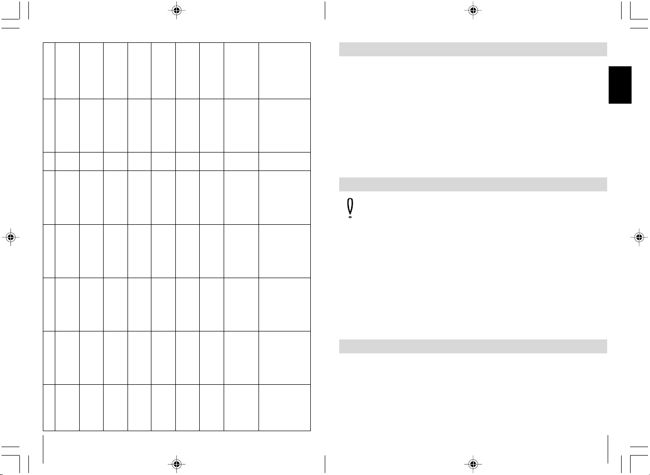
174
Audi 80 type 89 og
B4, modell: 86-94
Audi 100 og A6 type
C4, modell: 90-97
uten alarm
Audi 100 og A6 type
C4, modell: 90 - 97
med alarm
Audi A3 type 8L,
modell: 96-00
Audi A4 type B5,
modell: 94- uten
alarm
Audi A4 type B5
modell: 94 - med
alarm
BMW 3er E30,
modell: 82-90
BMW 3er E36,
modell: 91-
BMW 3er E36,
modell: 91-
Blinklys venstre,
kabelfarge, posisjon
sort/hvit, kabel-streng
venstre på terskel
sort/hvit, kabel-streng
venstre på terskel
sort/hvit, kabel-streng
venstre på terskel
sort/hvit, kabel-streng
venstre på terskel
sort/hvit, kabel-streng
venstre på terskel
sort/hvit, kabel-streng
venstre på terskel
grønn/blå, 30-polet hvitt
støpsel under
dashbordet
blå/grønn, kabelstreng
venstre på terskel
blå/grønn, kabelstreng
venstre på terskel
Blinklys høyre,
kabelfarge, posisjon
SL åpen
kabelfarge, posisjon
SL lukket
kabelfarge, posisjon
Koblings-
skjema
Dørkontakt
kabelfarge, posisjon
Anmerkning
sort/grønn, kabel-streng
venstre på terskel
sort/grønn, kabel-streng
venstre på terskel
sort/grønn, kabel-streng
venstre på terskel
sort/grønn, kabel-streng
venstre på terskel
sort/grønn, kabel-streng
venstre på terskel
sort/grønn, kabel-streng
venstre på terskel
grønn/sort / 30-polet
hvitt støpsel under
dashbordet
blå/brun, kabel-streng
venstre på terskel
blå/brun, kabel-streng
venstre på terskel
grønn/blå, A-søyle
venstre
grønn/blå, A-søyle
venstre, fra førerdøren
brun/grønn / A-søyle
venstre, fra førerdøren
grå/sort, A-søyle
venstre, fra førerdøren
grønn/blå / A-søyle
venstre, fra førerdøren
grå/hvit / A-søyle
venstre, fra førerdøren
grønn/blå, SL styre-
apparat pin 6
Pin 25, hvitt 26pol.
støpsel fra SL-styre-
apparat
Pin 4 / gul 26pol.
støpsel fra SL-styre-
apparat
grønn/blå, A-søyle
venstre
grønn/blå, A-søyle
venstre, fra førerdøren
brun/grå, A-søyle
venstre, fra førerdøren
brun/rød eller grå,
A-søyle venstre, fra
førerdøren
grønn/blå / A-søyle
venstre, fra førerdøren
brun/grå / A-søyle
venstre, fra førerdøren
gul/blå, SL styre-
apparat pin 7
Pin 24, hvitt 26 pol
støpsel fra SL styre-
apparat
Pin 17 / gul 26pol.
støpsel fra SL-styre-
apparat
Nr. 6
Nr. 6
Nr. 4
Nr. 4
Nr. 6
Nr. 4
Nr. 4
Nr. 3
Nr. 3
brun/hvit, på dør-kontakt
foran venstre på A-søyle,
dørkontakten er minus-
koblet
brun/gul på dør-kontakt
foran venstre på A-søyle,
dørkontakten er minus-
koblet
brun/gul, på dør-kontakt
foran venstre på A-søyle,
dørkontakten er minus-
koblet.
brun/hvit, på dør-kontakt
foran venstre på A-søyle,
dørkontakten er minus-
koblet.
grå, på dørkontakt foran
venstre på A-søyle,
dørkontakten er minus-
koblet
brun/hvit, på dør-kontakt
foran venstre på A-søyle,
dørkontakten er minus-
koblet
brun/gul, på dør-kontakt
foran venstre på A-søyle,
dørkontakten er minus-
koblet
brun/grå/gul, på
dørkontakt foran venstre
på B-søyle, dørkontakten
er minus-koblet
braun/grå/gul, på dør-
kontakt foran venstre på
B-søyle, dørkontakten
er minus-koblet
Tilkoble blå/gul styreledning
retning dør - grå/rød ledning
retning SL-pumpe
Tilkoble blå/gul styreledning
retning dør - grå/rød ledning
retning SL-pumpe
Tilkoble blå/gul styreledning
retning dør - grå/rød ledning
retning SL-pumpe
SL-styreapparat befinner
seg på venstre side i A-
søyle
Ev. trenges kontaktstifter
fra BMW med del-nr.
61131393704, SL-
styreapparat befinner seg
bak hanskerommet
Ev. trenges kontaktstifter
fra BMW med del-nr.
61131393704, SL-
styreapparat befinner seg
bak hanskerommet
27
D
Achtung! Wegen Kurzschlussgefahr vor Arbeiten an der
Fahrzeugelektrik immer den Minuspol abklemmen. Bei Fahrzeugen
mit Zusatzbatterie ebenfalls den Minuspol abklemmen.
Schließen Sie das Empfangsteil mit Hilfe des folgenden
Anschlussplanes (siehe ✎ J ➀), Steckerbelegungsplanes
(siehe ✎ J ➁) und dem Schaltplan (siehe ✎ J ➂ + ➃) an.
Durch den Anschluss an die Fahrtrichtungsanzeiger (Blinker) leuchten die
Blinker 1 x oder 2 x auf (falls gesetzlich erlaubt).
Belegungsplan (siehe ✎ J ➀)
Steckerbelegungsplan (siehe ✎ J ➁)
Schaltplan Türkontakt (-) minus geschaltet (siehe ✎ J ➂)
Schaltplan Türkontakt (+) plus geschaltet (siehe ✎ J ➃)
Elektrischer Anschluss des Empfangsteils
– Beispiel 3: Kabel an Masse legen
Kabel 5 mm abisolieren (siehe ✎ H ➀).
Ø 6 mm Krallen-Kabelschuh mit Krimpanschluss verwenden (siehe ✎ H ➁).
Kabelschuh mit Krimpzange auf das Kabelende krimpen (siehe ✎ H ➂).
Kabelschuh an einem Original Massepunkt anschrauben (siehe ✎ H ➃).
– Beispiel 4: Kabel mit Flachstecker versehen
Kabel 5 mm abisolieren (siehe ✎ I ➀).
Passenden Stecker mit Krimpanschluss (z.B. Flachsteckhülse) verwenden
(siehe ✎ I ➁).
Kabelschuh mit Krimpzange auf das Kabelende krimpen (siehe ✎ I ➂).
Falls erforderlich Steckanschluss mit Isolierhülse verwenden (siehe ✎ I ➃).
Kabelverlegung
Praktisch alle Zentralverriegelungen werden elektrisch gesteuert.
Bei Zentralverriegelungen, die in der Fahrertür keinen Stellmotor haben (diese
sind daran zu erkennen, dass sich die Fahrertür nicht von der Beifahrertür
aus ver- und entriegeln läßt), muss ein Stellmotor in der Fahrertür nachgerüstet werden. Hierfür kann der Einzelstellmotor, WAECO-Art.-Nr. ML-11,
verwendet werden. Dieser ist nach dem Schaltplan Nr. 1 (siehe ✎ K ➀)
anzuschließen.
Anschluss an der Zentralverrieglung
Page 28
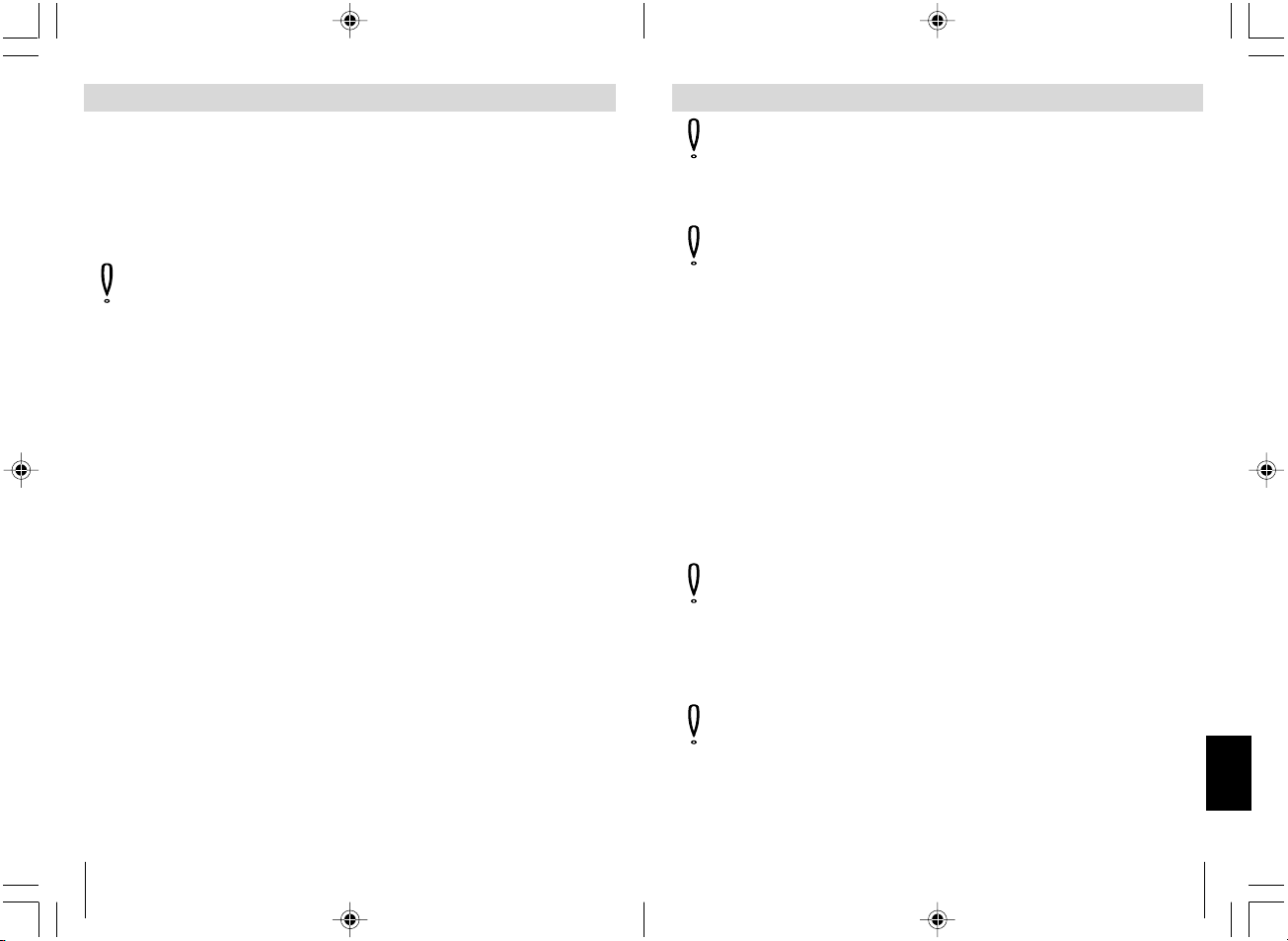
28
Bei allen anderen elektrisch gesteuerten Zentralverriegelungen muss zunächst die Funktionsweise herausgefunden werden. Hierzu nach Möglichkeit Originalschaltpläne von den Fahrzeug-Vertragswerkstätten verwenden.
Stehen keine Originalschaltpläne zur Verfügung, muss die Funktion der
Steuerleitungen, die von dem Zentralverriegelungs-Steuergerät zu der
Fahrzeugtür verlaufen, ausgemessen werden.
Achtung! Der Anschluss darf nur über die Steuerleitungen der
Zentralverriegelung und nicht über andere Leitungen erfolgen.
Der Anschluss an andere Leitungen als die Steuerleitungen oder
die Verwendung eines falschen Schaltbildes beim Anschluss,
kann zum Defekt der Zentralverriegelung und der Fernbedienung
führen.
Überprüfen Sie, wie die Zentralverriegelung Ihres Fahrzeuges
funktioniert.
Schließen Sie die Zentralverriegelung mit Hilfe der Schaltpläne
(siehe ✎ K ➀ – ➇) an.
Bei einigen Fahrzeugen, z.B. Mercedes, kann es sein, dass die Ansteuerungszeit von 0,6 Sek. nicht ausreicht, um die Zentralverriegelung
voll auszusteuern.
In solchen Fällen die Ansteuerungszeit mit dem DIP-Schalter 1
(siehe ✎ L ➀) auf 3,5 Sek. einstellen.
Im Normalfall ist der Wahlschalter 1 auf 0,6 Sek. eingestellt.
Der Anschluss an den Türkontakt für das automatische Wiederverschließen
ist für Fahrzeuge mit (-) Minus geschalteten Türkontakten und für Fahrzeuge mit + 12 Volt geschalteten Türkontakten geeignet.
Bei (-) Minus geschalteten Türkontakten die gelbe Leitung an die Schaltleitung anklemmen. Sollte diese Funktion nicht gewünscht sein, so muss die
gelbe Leitung an Masse angeschlossen werden.
Bei + 12 Volt geschalteten Türkontakten die grüne Leitung an die Schaltleitung anschließen (siehe ✎ J ➃). Sollte diese Funktion nicht gewünscht
sein, so wird die grüne Leitung nicht angeschlossen sondern isoliert.
Anschluss an der Zentralverrieglung
173
N
OBS! Koble aldri til begge ledningene (grønn og gul ledning).
Andre ledninger som ikke behøves skal alltid isoleres.
Koblingsskjema nr. 1 (se ✎ K ➀)
OBS! Dette koblingsskjemaet gjelder kun for biler uten servomotor i
bildøren hhv. for undertrykk-sentrallås uten elektrisk styreledning.
Koblingsskjema nr. 2 To styrende ledninger, minus og pluss,
begge +12 V (se ✎ K ➁)
Koblingsskjema nr. 3 To +12 V impulsstyrende ledninger (se ✎ K ➂)
Koblingsskjema nr. 4 To minusimpulsstyrende ledninger (se ✎ K ➃)
Koblingsskjema nr. 5 En åpen og ledning med minusimpuls
(se ✎ K ➄)
Koblingsskjema nr. 6 En ledning avvekslende med +12 V og
minusimpuls (se ✎ K ➅)
Koblingsskjema nr. 7 For tilkobling til WAECO sentrallås ML-44(22) IR
(se ✎ K ➆)
Viktig! Kontroller om blinklysene blinker 1x når du "låser" med
fjernkontrollen. Hvis de blinker 2x, må den blå/røde kabelen klemmes
om til den sorte kabelen og den grå/røde kabelen til den røde kabelen
på styreapparatet.
Koblingsskjema nr. 8 For tilkobling til WAECO sentrallås ML-44(22)
(se ✎ K ➇)
Viktig! Kontroller om blinklysene blinker 1x når du "låser" med
fjernkontrollen. Hvis de blinker 2x må den grå/røde kabelen klemmes
om til pin 5 og den blå/røde kabelen til pin 10 på styreapparatet.
Tilkobling til sentrallåsen
Page 29
172
På alle andre elektrisk styrte sentrallåser må du først finne ut hvordan de
funksjonerer. Bruk helst de originale koblingsskjemaene fra bilverkstedet
til dette.
Hvis du ikke har noen originale koblingsskjemaer, må du måle styreledningen
som går fra styreapparatet for sentrallåsen til bildøren.
OBS! Tilkoblingen må kun foretas over styreledningene for
sentrallåsen og ikke over andre ledninger.
Tilkobling til andre ledninger enn styreledningene eller
bruk av feil koblingsskjema ved tilkobling kan medføre at
sentrallåsen og fjernkontrollen blir skadet.
Kontroller hvordan sentrallåsen på bilen din funksjonerer.
Koble til sentrallåsen ved hjelp av koblingsskjemaene (se ✎ K ➀ – ➇).
Ved noen biler, f.eks. Mercedes, kan det være at aktiveringstiden på 0,6 Sek.
ikke er tilstrekkelig til å aktivere sentrallåsen fullstendig.
I slike tilfelle skal aktiveringstiden innstilles med DIP-bryter 1
(se ✎ L ➀) på 3,5 sek.
Vanligvis er kontrollbryter l innstilt på 0,6 sek.
Tilkobling til dørkontakten for den automatiske gjenlåsingen er egnet for
biler med (-) minus koblete dørkontakter og for biler med + 12 Volt koblete
dørkontakter.
Ved (-) minus koblete dørkontakter skal den gule ledningen klemmes på
tilkoblingsledningen. Hvis denne funksjonen ikke er ønsket, må den gule
ledningen kobles til jord.
Ved + 12 Volt koblete dørkontakter skal den grønne ledningen kobles til
koblingsledningen (se ✎ J ➃). Hvis denne funksjonen ikke er ønsket,
skal den grønne ledningen ikke tilkobles, men isoleres.
Tilkobling til sentrallåsen
29
D
Achtung! Nie beide Leitungen (Grüne und Gelbe Leitungen)
anschließen.
Weitere nicht benötigte Leitungen immer isolieren.
Schaltplan Nr. 1 (siehe ✎ K ➀)
Achtung! Dieser Schaltplan gilt nur für Fahrzeuge ohne Stellmotor
in der Fahrzeugtür bzw. für Unterdruck-Zentralverriegelung ohne
elektrische Steuerleitung.
Schaltplan Nr. 2 Zwei von Minus auf +12 V steuernde Leitungen
(siehe ✎ K ➁)
Schaltplan Nr. 3 Zwei +12 V impulssteuernde Leitungen (siehe ✎ K ➂)
Schaltplan Nr. 4 Zwei minusimpulssteuernde Leitungen (siehe ✎ K ➃)
Schaltplan Nr. 5 Eine offen und minusimpulssteuernde Leitung
(siehe K ➄)
Schaltplan Nr. 6 Eine +12 V und minusimpulssteuernde Leitung
(siehe ✎ K ➅)
Schaltplan Nr. 7 Für den Anschluss an WAECO Zentralverriegelung
ML-44(22) IR (siehe ✎ K ➆)
Wichtig! Kontrollieren Sie ob beim "Schließen" mit der Fernbedie-
nung die Blinkleuchten 1x blinken. Sollten sie 2x blinken, muss das
blau/rote Kabel auf das schwarze Kabel und das grau/rote Kabel auf
das rote Kabel des Steuergerätes umgeklemmt werden.
Schaltplan Nr. 8 Für den Anschluss an WAECO Zentralverriegelung
ML-44(22) (siehe ✎ K ➇)
Wichtig! Kontrollieren Sie ob beim "Schließen" mit der Fernbedie-
nung die Blinkleuchten 1x blinken. Sollten sie 2x blinken, muss das
grau/rote Kabel auf Pin 5 und das blau/rote Kabel auf Pin 10 des
Steuergerätes umgeklemmt werden.
Anschluss an der Zentralverrieglung
Page 30
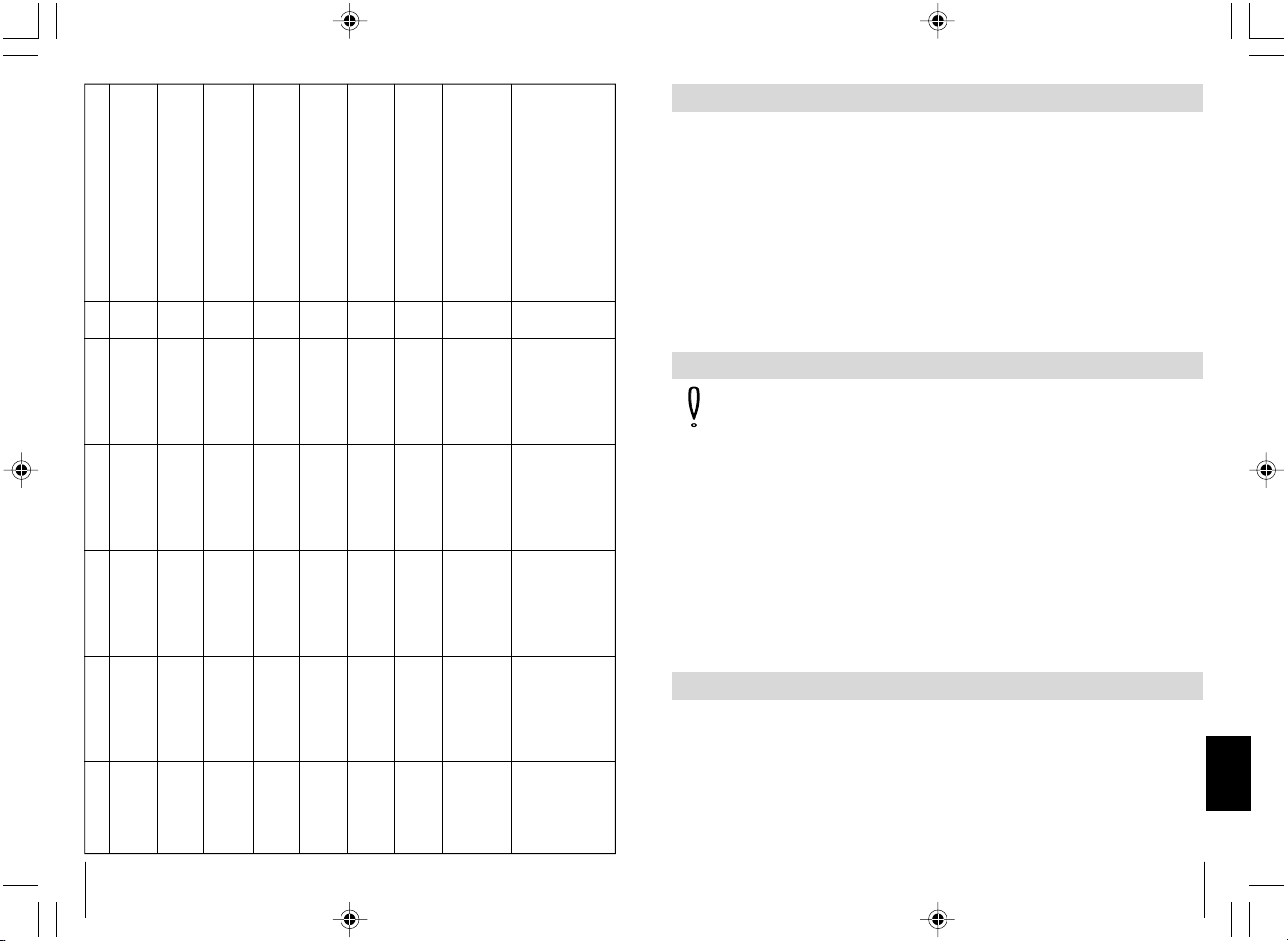
30
Audi 80 Typ 89 und
B4, Baujahr: 86-94
Audi 100 und A6
Typ C4, Baujahr: 90-
97 ohne DWA
Audi 100 und A6
Typ C4, Baujahr: 90
- 97 mit DWA
Audi A3 Typ 8L,
Baujahr: 96-00
Audi A4 Typ B5,
Baujahr: 94- ohne
DWA
Audi A4 Typ B5
Baujahr: 94 - mit
DWA
BMW 3er E30,
Baujahr: 82-90
BMW 3er E36,
Baujahr: 91-
BMW 3er E36,
Baujahr: 91-
Blinker links,
Kabelfarbe, Position
schwarz/weiß, Kabel-
strang links am
Schweller
schwarz/weiß, Kabel-
strang links am
Schweller
schwarz/weiß, Kabel-
strang links am
Schweller
schwarzweiß, Kabel-
strang links am
Schweller
schwarz/weiß, Kabel-
strang links am
Schweller
schwarz/weiß, Kabel-
strang links am
Schweller
grün/blau, 30-poliger
weißer Stecker unterm
Armaturenbrett
blau/grün, Kabelstrang
links am Schweller
blau/grün, Kabelstrang
links am Schweller
Blinker rechts,
Kabelfarbe, Position
ZV auf
Kabelfarbe, Position
ZV zu
Kabelfarbe, Position
Schalt-
plan
Türkontakt
Kabelfarbe, Position
Anmerkung
schwarz/grün, Kabel-
strang links am
Schweller
schwarz/grün, Kabel-
strang links am
Schweller
schwarz/grün /
Kabelstrang links am
Schweller
schwarz/grün,
Kabelstrang links am
Schweller
schwarz/grün /
Kabelstrang links am
Schweller
schwarz/grün, Kabel-
strang links am
Schweller
grün/schwarz / 30-
poliger weißer Stecker
unterm Armaturenbrett
blau/braun, Kabelstrang
links am Schweller
blau/braun, Kabelstrang
links am Schweller
grün/blau, A-Säule links
grün/blau, A-Säule
links, aus der Fahrertür
kommend
braun/grün / A-Säule
links, aus der Fahrertür
kommend
grau/schwarz, A-Säule
links, aus der Fahrertür
kommend
grün/blau / A-Säule
links, aus der Fahrertür
kommend
grau/weiß / A-Säule
links, aus der Fahrertür
kommend
grün/blau, ZV Steuer-
gerät Pin 6
Pin 25, weißer 26pol.
Stecker vom ZV-Steuer-
gerät
Pin 4 / gelber 26pol.
Stecker vom ZV-Steuer-
gerät
grün/blau, A-Säule links
grün/blau, A-Säule
links, aus der Fahrertür
kommend
braun/grau, A-Säule
links, aus der Fahrertür
kommend
braun/rot oder grau,
A-Säule links, aus der
Fahrertür kommend
grün/blau / A-Säule
links, aus der Fahrertür
kommend
braun/grau / A-Säule
links, aus der Fahrertür
kommend
gelb/blau, ZV Steuer-
gerät Pin 7
Pin 24, weißer 26 pol
Stecker vom ZV-Steuer-
gerät
Pin 17 / gelber 26pol.
Stecker vom ZV-Steuer-
gerät
Nr. 6
Nr. 6
Nr. 4
Nr. 4
Nr. 6
Nr. 4
Nr. 4
Nr. 3
Nr. 3
braun/weiß, am Tür-
kontakt vorne links an
der A-Säule, Türkontakt
ist minus geschaltet
braun/gelb am Tür-
kontakt vorne links an
der A-Säule, Türkontakt
ist minus geschaltet
braun/gelb, am Tür-
kontakt vorne links an
der A-Säule, Türkontakt
ist minus geschaltet.
braun/weiß,am Tür-
kontakt vorne links an
der A-Säule, Türkontakt
ist minus geschaltet.
grau, am Türkontakt
vorne links an der
A-Säule, Türkontakt ist
minus geschaltet
braun/weiß, am Tür-
kontakt vorne links an
der A-Säule, Türkontakt
ist minus geschaltet
braun/gelb, am Tür-
kontakt vorne links an
der A-Säule, Türkontakt
ist minus geschaltet
braun/grau/gelb, am
Türkontakt vorne links
an der B-Säule,
Türkontakt ist minus
geschaltet
braun/grau/gelb, am
Tür-kontakt vorne links
an der B-Säule,
Türkontakt ist minus
geschaltet
blau/gelbe Steuerleitung
Richtung Tür - grau/rote
Leitung Richtung ZV-
Pumpe anschliessen
blau/gelbe Steuerleitung
Richtung Tür - grau/rote
Leitung Richtung ZV-
Pumpe anschliessen
blau/gelbe Steuerleitung
Richtung Tür - grau/rote
Leitung Richtung ZV-
Pumpe anschliessen
ZV-Steuergerät befindet
sich auf der linken Seite
in der A-Säule
Evtl. werden Kontaktstifte
von BMW mit der Teile-
Nr. 61131393704
benötigt, ZV-Steuergerät
befindet sich hinterm
Handschuhfach
Evtl. werden Kontaktstifte
von BMW mit der Teile-
Nr. 61131393704
benötigt, ZV-Steuergerät
befindet sich hinterm
Handschuhfach
171
N
OBS! På grunn av kortslutningsfare skal du alltid ta av minuspolen
før du arbeider på bilelektronikken. På biler med ekstrabatteri skal
minuspolen tas av også der.
Koble til mottakerdelen ved hjelp av følgende koblingsskjema
(se ✎ J ➀), pluggtilordningsskjema (se ✎ J ➁) og koblingsskjema
(se ✎ J ➂ + ➃).
Ved tilkobling til retningsviserne (blinklys) lyser blinklysene 1 x eller 2 x
(hvis tillatt ved lov).
Tilordningsskjema (se ✎ J ➀)
Pluggtilordningsskjema (se ✎ J ➁)
Koblingsskjema dørkontakt (-) minus koblet (se ✎ J ➂)
Koblingsskjema dørkontakt (+) pluss koblet (se ✎ J ➃)
Elektrisk tilkobling av mottakerdelen
– Eksempel 3: Legge kabel på jord
Avisoler kabelen 5 mm (se ✎ H ➀).
Bruk Ø 6 mm klo-kabelsko med krympetilkobling (se ✎ H ➁).
Krymp kabelskoen på kabelenden med krympetangen (se ✎ H ➂).
Skru kabelskoen på et originalt jordpunkt (se ✎ H ➃).
– Eksempel 4: Sette flatstiftplugg på kabelen
Avisoler kabelen 5 mm (se ✎ I ➀).
Bruk et passende støpsel med krympetilkobling (f.eks. flatstifthylse)
(se ✎ I ➁).
Krymp kabelskoen på kabelenden med krympetangen (se ✎ I ➂).
Bruk pluggforbindelse med isolerhylse om nødvendig (se ✎ I ➃).
Kabellegging
Nesten alle sentrallåser er elektrisk styrt.
Ved sentrallåser der det ikke finnes noen servomotor i førerdøren (førerdøren
kan ikke låses opp og igjen fra passasjerdøren), må det monteres en
servomotor i førerdøren. Man kan bruke enkeltservomotor, WAECO-art.-nr.
ML-11. Denne skal kobles til i henhold til koblingsskjema nr. 1 (se ✎ K ➀).
Tilkobling til sentrallåsen
Page 31

170
– Pass på at det er tilstrekkelig avstand fra mottaker og kabelsett til
mekanisk bevegete bildeler, som f.eks. rattsøyle eller bremsepedal, clutch
og gasspedal, for å forhindre skader på kabelen ved at den blir klemt eller
slitt.
– Hvis du installerer mottakeren bak kledninger, må du passe på at
du kan montere kledningene igjen etterpå.
– Når du fester mottakeren med skruer må du passe på at
ingen andre bildeler blir skadet.
Montering av mottakerdelen
Kabler som ikke legges eller forbindes riktig forårsaker stadig at
komponenter funksjonerer feil eller blir skadet. At kabler er lagt hhv. forbundet
riktig er en forutsetning for at de senere innebyggete komponentene
funksjonerer varig og feilfritt.
Følg disse punktene:
– Legg kablene slik at de ikke kan bli skadet.
Ikke legg kablene langs skarpe kanter, varme eller bevegelige bildeler.
– Legg kablene langs originale kabelgrener og forbind dem så ofte som
mulig med isolerbånd og kabelbindere.
– Hvis du legger kabelen fra bilkupéen til motoren eller bagasjerommet,
skal du bruke de gjennomføringsbøssingene som finnes i skilleveggene.
– Bruk kun egnete måter for å koble til kabelen. Se de fire eksemplene
nedenfor.
– Eksempel 1: Koble kabelen til originale ledninger.
Avisoler 10 mm fra den originale ledningen (se ✎ F ➀).
Avisoler 15 mm fra den kabelen som skal tilkobles (se ✎ F ➁).
Vikle den kabelen som skal tilkobles rundt den originale ledningen og
lodd sammen (se ✎ F ➂).
Isoler kabelen med isolerbånd (se ✎ F ➃).
– Eksempel 2: Forbinde 2 kabler med hverandre.
Avisoler begge kablene (se ✎ G ➀).
Trekk en krympeslange på ca. 20 mm lengde over kabelen (se ✎ G ➁).
Tvinn begge kablene med hverandre og lodd dem sammen (se ✎ G ➂).
Skyv krympeslangen over loddestedet og varm den litt opp (se ✎ G ➃).
Kabellegging
31
D
BMW 3er E36
Baujahr: 93- mit
Alarm
BMW 5er E34,
Baujahr: 88-95
BMW 5er E34,
Baujahr: 88-95
Mercedes 200-
W124, Baujahr: -95
Mercedes 190 W201,
Baujahr: -94
Mercedes C180-
W202 Baujahr: 94-
Opel Astra F und G,
Baujahr: 92-
Opel Calibra,
Baujahr: 90-
Blinker links,
Kabelfarbe, Position
blau/grün, Kabelstrang
links am Schweller
blau/grün, Kabelstrang
links am Schweller
blau/grün, Kabelstrang
links am Schweller
schwarz/weiß, Kabel-
strang links am
Schweller
schwarz/weiß, Kabel-
strang links am
Schweller
schwarz/weiß, Kabel-
strang links am
Schweller
schwarz/weiß, Kabel-
strang links am
Schweller
schwarz/weiß, Kabel
strang links am
Schweller
Blinker rechts,
Kabelfarbe, Position
ZV auf
Kabelfarbe, Position
ZV zu
Kabelfarbe, Position
Schalt-
plan
Türkontakt
Kabelfarbe, Position
Anmerkung
blau/braun / Kabelstrang
links am Schweller
blau/braun, Kabelstrang
links am Schweller
blau/braun, Kabelstrang
links am Schweller
schwarz/grün, Kabel-
strang links am
Schweller
schwarz/grün, Kabel-
strang links am
Schweller
schwarz/grün, Kabel-
strang links am
Schweller
grün/schwarz, Kabel-
strang links am
Schweller
grün/schwarz, Kabel-
strang links am
Schweller
Pin 25 / weißer 26pol.
Stecker vom ZV-
Steuergerät
(bis 9/91) Pin 2 oder 6,
weißer 26pol. Stecker
vom ZV-Steuergerät
(ab 9/91) Pin 25, weißer
26pol. Stecker vom ZV-
Steuergerät
Pin 16 / gelber 26pol.
Stecker vom vom ZV-
Steuergerät
blau, A-Säule links, aus
der Fahrertür kommend
blau, A-Säule links, aus
der Fahrertür kommend
blau, A-Säule links, aus
der Fahrertür kommend
braun/weiß, A-Säule
links, aus der Fahrertür
kommend
braun/weiß, A-Säule
links, aus der Fahrertür
kommend
Pin 19 / weißer 26pol.
Stecker vom ZV-Steuer-
gerät
(bis 9/91) Pin 1, weißer
26pol. Stecker vom ZV-
Steuergerät
(ab 9/91) Pin 24, weißer
26pol. Stecke vom ZV-
Steuergerät
Pin 7, gelber 26pol.
Stecker vom ZV-Steuer-
gerät
blau, A-Säule links, aus
der Fahrertür kommend
blau, A-Säule links, aus
der Fahrertür kommend
schwarz, A-Säule links,
aus der Fahrertür
kommend
braun/rot, A-Säule links,
aus der Fahrertür
kommend
braun/rot, A-Säule links,
aus der Fahrertür
kommend
Nr. 3
Nr. 3
Nr. 3
Nr. 6
Nr. 6
Nr. 4
Nr. 4
Nr. 4
braun/grau/gelb, am Tür-
kontakt vorne links an der
B-Säule, Türkontakt ist
minus geschaltet
braun/violett, am
Türkontakt vorne links
an der B-Säule,
Türkontakt ist minus
geschaltet
braun/violett, am
Türkontakt vorne links
an der B-Säule
braun/weiß,am Tür-
kontakt vorne links an
der A-Säule, Türkontakt
ist minus geschaltet
braun/weiß, am Tür-
kontakt vorne links an
der A-Säule, Türkontakt
ist minus geschaltet
braun/weiß, am Tür-
kontakt vorne links an
der B-Säule, Türkontakt
ist minus geschaltet
braun/weiß, am Tür-
kontakt vorne links an
der A-Säule, Türkontakt
ist minus geschaltet
grau,am Türkontakt
vorne links an der A-
Säule, Türkontakt ist
minus geschaltet
Evtl. werden Kontaktstifte
von BMW mit der Teile-
Nr. 61131393704
benötigt, ZV-Steuergerät
befindet sich hinterm
Handschuhfach
Evtl. werden Kontaktstifte
von BMW mit der Teile-
Nr. 61131393704
benötigt, ZV-Steuergerät
befindet sich unter der
Rücksitzbank
Evtl. werden Kontaktstifte
von BMW mit der Teile-
Nr. 61131393704
benötigt, ZV-Steuergerät
befindet sich unter der
Rücksitzbank
blau/gelbe Steuerleitung
Richtung Tür u. die grau/
rote Leitung Richtung ZV
Pumpe anschliessen
blau/gelbe Steuerleitung
Richtung Tür u. die grau/
rote Leitung Richtung ZV
Pumpe anschliessen
Page 32

32
Opel Corsa A, B
Baujahr: 93-2000
Opel Kadett E,
Baujahr: 90-
Opel Omega A und
B, Baujahr: 90-
Opel Vectra A und B
VW Golf lll und
Vento Typ 1HXO,
Baujahr: 91-
VW Golf lV Baujahr:
97- mit elektrischen
Fensterhebern
VW Golf lV Baujahr:
97- ohne elektrische
Fensterheber
VW Lupo Baujahr:
98-
VW Passat 35i,
Baujahr: 88-92
VW Passat 35i,
Baujahr: 93-96
Blinker links,
Kabelfarbe, Position
schwarz/weiß, Kabel-
strang links am
Schweller
schwarz/weiß, Kabel-
strang links am
Schweller
schwarz/weiß, Kabel-
strang links am
Schweller
schwarz/weiß, Kabel-
strang links am
Schweller
schwarz/weiß, Kabel-
strang links am
Schweller
schwarz/weiß, Kabel-
strang links am
Schweller
schwarz/weiß, Kabel-
strang links am
Schweller
schwarz/weiß, Kabel-
strang links am
Schweller
schwarz/weiß, Kabel-
strang links am
Schweller
schwarz/weiß, Kabel-
strang links am
Schweller
Blinker rechts,
Kabelfarbe, Position
ZV auf
Kabelfarbe, Position
ZV zu
Kabelfarbe, Position
Schalt-
plan
Türkontakt
Kabelfarbe, Position
Anmerkung
grün/schwarz, Kabel-
strang links am
Schweller
grün/schwarz,
Kabelstrang links am
Schweller
grün/schwarz, Kabel-
strang links am
Schweller
grün/schwarz, Kabel-
strang links am
Schweller
schwarz/grün, Kabel-
strang links am
Schweller
schwarz/grün, Kabel-
strang links am
Schweller
schwarz/grün, Kabel-
strang links am
Schweller
schwarz/grün, Kabel-
strang links am
Schweller
schwarz/grün, Kabel-
strang links am
Schweller
schwarz/grün, Kabel-
strang links am
Schweller
braun/weiß / A-Säule
links, aus der Fahrertür
kommend
braun/weiß, A-Säule
links, aus der Fahrertür
kommend
braun/weiß, A-Säule
links, aus der Fahrertür
kommend
braun/weiß, A-Säule
links, aus der Fahrertür
kommend
grün, A-Säule links, aus
der Fahrertür kommend
gelb/grün Pin 24, am
Tür-steuergerät,
Fahrerseite
gelb/grün, ZV-Steuer-
gerät grauer Stecker 24
pol. unterhalb der Arma-
turentafel
blau/violett, A-Säule
links, aus der Fahrertür
kommend
schwarz/weiß, A-Säule
links, aus der Fahrertür
kommend
grün, A-Säule links, aus
der Fahrertür kommend
braun/rot / A-Säule links,
aus der Fahrertür
kommend
braun/rot, A-Säule links,
aus der Fahrertür
kommend
braun/rot, A-Säule links,
aus der Fahrertür
kommend
braun/rot / A-Säule
links, aus der Fahrertür
kommend
grau, A-Säule links, aus
der Fahrertür kommend
gelb/blau Pin 4, am Tür-
steuergerät, Fahrerseite
gelb/blau oder blau, ZV-
Steuergerät grauer
Stek-ker 24 pol.
unterhalb der
Armaturentafel
grau/gelb, A-Säule
links, aus der Fahrertür
kom-mend
rot/gelb, A-Säule links,
aus der Fahrertür kom-
mend
grau, A-Säule links, aus
der Fahrertür kommend
Nr. 4
Nr. 4
Nr. 4
Nr. 4
Nr. 3
Nr. 4
Nr. 4
Nr. 4
Nr. 3
Nr. 3
grau, am Türkontakt
vorne links an der A-
Säule, Türkontakt ist
minus geschaltet
grün, am Türkontakt
vorne links an der A-
Säule, Türkontakt ist
minus geschaltet
grau, am Türkontakt
vorne links an der A-
Säule, Türkontakt ist
minus geschaltet
grau/weiß oder braun/
weiß, am Türkontakt
vorne links an der A-
Säule, Türkontakt ist
minus geschaltet
braun/weiß, am Tür-
kontakt vorne links an
der A-Säule, Türkontakt
ist minus geschaltet
braun/weiß, am Tür-
kontakt vorne links an
der A-Säule, Türkontakt
ist minus geschaltet
blau/grau, am ZV
Steuergerät auf Pin 18,
Türkontakt ist minus
geschaltet
braun/weiß, in der
Kabeldurchführung an
der A-Säule, Türkontakt
ist minus geschaltet
braun/weiß, am Tür-
kontakt vorne links an
der A-Säule, Türkontakt
ist minus geschaltet
braun/weiß, am Tür-
kontakt vorne links an
der A-Säule, Türkontakt
ist minus geschaltet
Das Türsteuergerät be-
findet sich am Fenster-
heber unterhalb der Tür-
verkleidung
ZV-Steuergerät ist links
neben der Lenksäule. Die
Kabelfarben findet man
auch in der A-Säule
169
N
Leveringsomfang
Nr. Mengde Betegnelse Artikkel-nr.
(se ✎ B ➀) 1 Mottakerdel Art. nr. MT-350RX
(se ✎ B ➁) 2 Håndsender Art. nr. MT-650TX
(se ✎ B ➂) 1 Tilkoblingskabel mottakerdel Art. nr. MT-350KA
Nødvendig verktøy
Du trenger for innbygging og montering:
– Målestokk (se ✎ C ➀) – Bor (se ✎ C ➃)
– Kjørner (se ✎ C ➁) – Boremaskin (se ✎ C ➄)
– Hammer (se ✎ C ➂) – Skrutrekker (se ✎ C ➅)
For elektrisk tilkobling og kontroll trenger du:
– Diodeprøvelampe (se ✎ D ➀) – Varmekrympeslange
eller voltmeter (se ✎ D ➁) – Varmluftføn (se ✎ D ➃)
– Krympetang (se ✎ D ➂) – Loddebolt (se ✎ D ➄)
– Isolerbånd – Loddetinn (se ✎ D ➅)
For å feste mottaker og kabel trenger du ev. flere skruer, plateskruer og
kabelbindere.
Finn et egnet monteringssted for mottakerdelen. Egnete
monteringssteder (se ✎ E ➀) finnes under dashbordet, bak
midtkonsollen eller bak hanskerommet.
Henvisninger for valg av monteringssted:
– Mottakeren skal være lett tilgjengelig slik at det er mulig
å etterprogrammere håndsendere.
– Ikke fest mottakeren rett ved siden av andre styreapparater.
Dette gjør at apparatene forstyrrer hverandre. Det kan oppstå
feilfunksjoner og fjernkontrollens rekkevidde blir redusert.
Montering av mottakerdelen
Page 33

168
Fjernkontrollens funksjoner
Låse sentrallåsen
Når du trykker på den venstre blå tasten på håndsenderen blir sentrallåsen
låst. Dette bekreftes med at blinklyset blinker 1x.
Låse opp sentrallåsen
Når du trykker en gang til på den venstre blå tasten på håndsenderen blir
sentrallåsen låst opp. Dette bekreftes med at blinklyset blinker 2x.
Komfortfunksjon
Når du trykker på den høyre grå tasten på håndsenderen blir
komfortutgangen aktivert (når bilen er låst) og styrer alt etter tilkobling
vindusløftere, et alarmanlegg eller en kupévarmer.
OBS! Den maksimale strømmen for denne komfortfunksjonen må
ikke overskride 150 mA. Hvis større forbrukere blir aktivert må det
settes inn et tilleggsrelé (arbeidsstrømrelé) med en friløpsdiode.
Automatisk gjenlåsing
Hvis håndsenderen blir betjent av vanvare (sentrallåsen åpnes) og ingen
dør blir åpnet, blir sentrallåsen låst igjen etter ca. ett minutt. Hvis du ikke ønsker
denne funksjonen, må den gule styreledningen kobles til jord og den grønne
ledningen må isoleres.
Sikkerhetslås
Sentrallåsen kan låses med håndsenderen når tenningen er slått på.
Blinklysene blir da ikke aktivert. Sentrallåsen kan åpnes igjen over
håndsenderen eller ved at tenningen slås av. Denne funksjonen finnes
ikke for alle bilmodeller.
Kupélys
Kupélyset blir slått på når sentrallåsen låses opp og slukner når tenningen
slås på.
Denne funksjonen er aktiv på biler med negativt (jord) koblete dørkontakter.
33
D
VW Passat 3B,
Baujahr: 9/97-
VW Polo 6N,
Baujahr: 95-
VW Sharan 7M,
Baujahr: 96-
VW T4 Baujahr: 93-
Blinker links,
Kabelfarbe, Position
schwarz/weiß, Kabel-
strang links am
Schweller
schwarz/weiß, Kabel-
strang links am
Schweller
schwarz/weiß, Kabel-
strang, links am
Schweller
schwarz/weiß, Kabel-
strang links am
Schweller
Blinker rechts,
Kabelfarbe, Position
ZV auf
Kabelfarbe, Position
ZV zu
Kabelfarbe, Position
Schalt-
plan
Türkontakt
Kabelfarbe, Position
schwarz/grün, Kabel-
strang links am
Schweller
schwarz/grün, Kabel-
strang links am
Schweller
schwarz/grün, Kabel-
strang links am
Schweller
schwarz/grün, Kabel-
strang links am
Schweller
rot/blau / Pin 4 vom orig.
ZV - Steuergerät
grau/schwarz, A-Säule
links, aus der Fahrertür
kommend
grün, A-Säule links, aus
der Fahrertür kommend
gelb, A-Säule links, aus
der Fahrertür kommend
braun/blau, Pin 2 vom
orig. ZV - Steuergerät
grau/rot, A-Säule links,
aus der Fahrertür
kommend
grau, A-Säule links, aus
der Fahrertür kommend
weiß, A-Säule links, aus
der Fahrertür kommend
Nr. 4
Nr. 3
Nr. 3
Nr. 3
braun/weiß, in der
Kabeldurchführung an
der A-Säule, Türkontakt
ist minus geschaltet
braun/weiß, am Tür-
kontakt vorne links an
der A-Säule, Türkontakt
ist minus geschaltet
braun/weiß, in der
Kabeldurchführung an
der A-Säule, Türkontakt
ist minus geschaltet
braun/weiß, hinterm
Sicherungskasten,
Türkontakt ist minus
geschaltet
Vor dem Anschluss ist die Polarität zu prüfen.
Änderungen vorbehalten.
Weitere Fahrzeuge auf Anfrage möglich.
Anmerkung
Zentralverriegelung ist
Masse gesteuert. In die
blau/rote Leitung muss
ein 200W Widerstand
eingesetzt werden, ZV-
Steuergerät ist in einer
schwarzen Box im Fahrer
fußraum unterm Teppich
Page 34

34
Löschen von Handsendern
Sie können Handsender (z. B. verloren gegangener Handsender) von der
Benutzung Ihrer Funkfernbedienung ausschließen, indem Sie die funktionsberechtigten Handsender 5 x hintereinander neu codieren. Gehen Sie
hierzu so vor, wie im nachfolgenen Abschnitt "Nachcodieren von Handsendern" beschrieben.
Öffnen Sie das Fahrzeug mit dem Handsender
Setzen Sie sich in das Fahrzeug. Alle Türen sollten geschlossen
aber nicht verriegelt sein.
Nachcodieren von Handsendern
Schaltereinstellungen am Funk-Empfangsteil
Hinweis! Damit die Einstellungen vom Funk-Empfangsteil erkannt werden,
muss zuvor der Anschlussstecker herausgezogen werden.
DIP Schalter 1 (siehe ✎ L ➀)
Mit diesem Wahlschalter wird die Steuerzeit für das Relais zur Zentralverriegelungsansteuerung eingestellt.
Stellung On "3,5 Sek."
Die Original ZV wird 3,5 Sek. lang angesteuert.
Diese Stellung wird bei einigen Original ZV's benötigt, die pneumatisch
arbeiten und daher für den Schließvorgang mehr als 0,6 Sek. Zeit benötigen.
Stellung Off "0,6 Sek."
Diese Stellung ist für alle elektrischen ZV's, die in der Regel weniger als
0,6 Sek. Zeit für den Schließvorgang benötigen.
DIP Schalter 2 (siehe ✎ L ➁)
Mit diesem Wahlschalter wird die Steuerfunktion des Komfortanschlusses
eingestellt.
Stellung On
Ausgang nach Betätigen der grauen Taste aktiv. Durch erneutes Betätigen
einer Sendetaste deaktiviert.
Stellung Off
Der Ausgang bleibt nach dem Betätigen der grauen Taste für 10 sek. aktiv.
167
N
Følgende data må alt etter bilens utstyr legges inn på nytt:
Radiokode · bilklokke · koblingsklokke · kjørecomputer · seteposisjon
Du finner henvisninger om innstillingen i vedkommende bruksanvisning.
Advarsel! Deler av MAGIC TOUCH MT-350 som er montert i bilen må
festes slik at de ikke under noen omstendigheter (bråbremsing,
trafikkuhell) kan løsne og forårsake personskader hos
passasjerene.
OBS! For kontroll av spenningen i de elektriske ledningene
må det kun brukes en diodeprøvelampe (se ✎ A ➀) eller et voltmeter
(se ✎ A ➁). Prøvelamper (se ✎ A ➂) med et lyselement opptar for
høy strøm og kan skade bilelektronikken.
OBS! Pass på at det er nok fritt rom der boret kommer ut slik at
skader kan unngås (se ✎ A ➃). Hvert boret hull skal avgrades og
behandles med rustbeskyttelsesmiddel.
Sikkerhets- og monteringshenvisninger
Innledning
MT-350 fjernkontroll er et tillegg til sentrallåsen på bilen. Du åpner og lukker
dørene på bilen med en liten sender. Funksjonsutvidelser, som f. eks.
aktivering av de elektriske vindusløfterne, driften for soltaket eller
kupévarmer er mulig med tilleggsmoduler.
Forutsetninger for at fjernkontrollen funksjonerer
Bilen må ha en driftsspenning på 12 V.
Bilen må være utstyrt med en sentrallås.
Noen produsenter utstyrer bilene med en spare-sentrallås. Disse bilene har
ingen servomotor i førerdøren, men bare en elektrisk bryter. I disse bilene må
det bygges inn en servomotor (f.eks. WAECO art. nr.: ML-11). Bruk denne
fremgangsmåten for å fastslå om det finnes en servomotor:
– Lås bilen fra passasjersiden.
– Hvis førerdøren er låst, finnes det en servomotor.
– Hvis førerdøren ikke er låst, må det bygges inn en servomotor i
førerdøren (f.eks. WAECO art. nr.: ML-11).
Page 35

166
Sikkerhets- og monteringshenvisninger
Advarsel! Utilstrekkelige ledningsforbindelser kan forårsake at
det pga. kortslutning:
– oppstår kabelbrann
– kollisjonsputen utløses
– elektroniske styringsinnretninger blir skadet
– elektriske funksjoner (blinklys, bremselys, horn, tenning, lys)
svikter
Følg derfor disse henvisningene:
Ved arbeider på ledninger:
30 (Inngang fra batteri pluss direkte),
15 (Koblet pluss, bak batteri)
31 (Returledning fra batteri, jording)
L (Blinklys venstre)
R (Blinklys høyre)
Den sikreste forbindelsesmåten er å lodde kabelendene med hverandre
og deretter isolere dem.
Bruk kun isolerte kabelsko, støpsler og flatstikkhylser for forbindelser som
kan tas fra hverandre. Ikke bruk krympeforbindelse (ledningsforbindelser)
eller lysterklemmer.
Bruk en krympetang for å forbinde kabelen med kabelsko, støpsel eller
flatstikkhylser.
Ved kabelkoblinger på 31 (jord):
Skru kabelen med kabelsko og tannskive på en jordskrue i bilen eller
skru den med kabelsko, plateskrue og tannskive på karosseriplaten.
Pass på god jordoverføring!
Advarsel! På grunn av kortslutningsfare skal minuspolen på batteriet
alltid tas av før du begynner med arbeider på elektrisk utstyr i bilen.
På biler med ekstrabatteri skal minuspolen tas av også der.
OBS! Når minuspolen tas av batteriet går de lagrete data i alle
flyktige lager for komfort-elektronikken tapt.
35
D
Schritt 1: Schalten Sie die Zündung ein.
Schritt 2: Betätigen Sie nun innerhalb von 10 Sekunden gleichzeitig
beide Tasten eines aktiven funktionsfähigen Handsenders. Die
Anlage befindet sich nun im Codiermodus. Als Bestätigung wird
das Fahrzeug verriegelt.
Schritt 3: Betätigen Sie die blaue Taste des neuen Handsenders
bis zur Bestätigung der neuen Codierung die Zentralverriegelung
geöffnet wird.
Schritt 4: Testen Sie den neuen Handsender. Funktioniert der neue
Handsender nicht, so müssen die vorherigen Arbeitsschritte wiederholt werden.
Zentralverriegelung öffnen/schließen
Das Öffnen und Schließen des Fahrzeugs wird über die blaue Taste des
Handsenders gesteuert. Das Öffnen wird durch zwei Blinkzeichen bestätigt.
Das Schließen wird durch ein Blinkzeichen bestätigt.
Nach dem Öffnen des Fahrzeugs wird das Innenraumlicht eingeschaltet
und nach dem Einschalten der Zündung oder nach 30 Sek. wieder
ausgeschaltet (nur für negativ geschaltete Türkontakte).
Komfortfunktionen schalten
Der Ausgang für Komfortfunktionen wird über die graue Taste eingeschaltet
(nur bei verriegeltem Fahrzeug). Je nach Einstellung des Empfängers wird
der Ausgang für 10 sek. geschaltet oder solange geschaltet, bis eine
Sendertaste betätigt wird. Das Einschalten der Komfortfunktion wird durch
ein Blinkzeichen bestätigt.
Achtung! Der maximale Ausgangsstrom (Minus geschaltet) für
diese Komfortfunktion darf 150 mA nicht übersteigen. Bei Ansteuerung von größeren Verbrauchern muss ein Zusatzrelais
(MT-RELAY) eingesetzt werden.
Achtung - Quetschgefahr! Fensterheber nie unbeaufsichtigt
schließen lassen.
Zur einwandfreien Funktion der Fernbedienung ist eine störungsfreie Funkverbindung zwischen Sender und Empfänger erforderlich.
Bedienungsanleitung
Nachcodieren von Handsendern
Page 36

36
Die Reichweite beträgt je nach Einbausituation des Empfängers und
Sendeleistung der Störquellen in der Umgebung bis zu 20 m.
Der Handsender sendet bei jeder Betätigung einen neuen Code (Wechselcode). Bei zu häufigem Betätigen des Handsenders, ohne dass der
Empfänger das Sendersignal empfängt, kann es sein, dass der Empfänger
den Handsender nicht sofort erkennt. Sie müssen dann den Handsender
noch 1-2 mal betätigen. Spätestens beim dritten Mal senden erkennt der
Empfänger den Sender wieder.
Bedienungsanleitung
Läßt die Reichweite des Handsenders merklich nach oder flackert die
Kontroll-LED beim Senden, so muss die Batterie ausgetauscht werden.
Verwenden Sie nur auslaufsichere und für elektronische Geräte geeignete
Batterien. Halten Sie die Batterien außer der Reichweite von Kindern.
Versuchen Sie nie Batterien wieder aufzuladen, zu öffnen oder ins Feuer
zu werfen.
Schützen Sie Ihre Umwelt! Gebrauchte Batterien gehören nicht in den
Hausmüll, sondern werden in öffentlichen Sammelbehältern oder bei Ihrem
Händler gesammelt und fachgerecht entsorgt.
Drehen Sie die Schraube auf der Unterseite des Handsenders heraus und
öffnen Sie den Sender. Tauschen Sie die Batterie. Achten Sie beim
Einlegen der Batterie auf die richtige Polung (Batterietyp CR 2032 3 Volt).
Der Pluspol ist oben. Erhältlich ist die Batterie z.B. in Fotoläden, Uhrengeschäften, usw.
Setzen Sie den Deckel des Handsenders wieder auf und drehen Sie die
Schraube wieder herein.
Batteriewechsel
165
N
Advarsel! Sikkerhetshenvisning:
Hvis dette ikke følges kan det oppstå person- eller materialskader.
OBS! Sikkerhetshenvisning:
Hvis dette ikke følges kan det oppstå materialskader og funksjonen
av MAGIC TOUCH MT-350 kan påvirkes.
Romben er tegn for monteringsskritt som du må utføre.
For å kunne foreta monteringen uten vanskeligheter, bør du lese
denne monterings- og betjeningsanvisningen før du begynner
monteringen.
Hvis MAGIC TOUCH MT-350 skifter eier må denne monteringsog betjeningsanvisningen følge med.
Henvisninger om bruk av monteringsanvisningen
Tittel Side
Bilder til monteringanvisningen 3-19
Innhold 165
Henvisninger om bruk av monteringsanvisningen 165
Sikkerhets- og monteringshenvisninger 166-167
Innledning 167
Forutsetninger for at fjernkontrollen funksjonerer 167
Fjernkontrollens funksjoner 168
Leveringsomfang 169
Nødvendig verktøy 169
Montering av mottakerdelen 169-170
Kabellegging 170-171
Elektrisk tilkobling av mottakerdelen 171
Tilkobling til sentrallåsen 171-173
Bilspesifikke henvisninger 174-177
Bryterinnstillinger på mottakerdelen 178
Sletting av håndapparater 178
Etterkoding av håndsendere 178-179
Betjeningsanvisning 179-180
Skifte batteri 180
Tekniske data 181
Innholdsfortegnelse
Page 37

164
37
D
Betriebsspannung: 9 - 16 V DC
Ruhestromaufnahme: 5 mA
Max. Stromaufnahme: 16 A kurzzeitig
Betriebstemperatur: -40 bis +85 °C Empfänger
-20 bis +60 °C Sender
Sendefrequentz: 433,92 MHz
Reichweite: 10 m ... 20 m
Schaltstrom Zentralverriegelung: max. 10 A
Schaltstrom Blinkeransteuerung: max. 2 x 5 A
Schaltstrom Zusatzausgang: max. 150 mA
Zentralverriegelungssteuerzeit: wahlweise 0,6/3,5 Sek.
Blinkersteuerzeit: 1 x 0,75 Sek. / 2 x 0,75 Sek./
Ein /Aus
Größe des Handsenders (L x B x H): 52 x 35 x 13 mm
Größe des Empfängers (L x B x H): 97 x 140 x 32 mm
Technische Daten
Page 38

38
163
S
Driftspänning: 9 - 16 V DC
Viloströmsförbrukning: 5 mA
Max. strömförbrukning: 16 A under kort tid
Drifttemperatur: -40 till +85°C mottagare
-20 till +60°C sändare
Sändningsfrekvens: 433,92 MHz
Räckvidd: 10 m ... 20 m
Brytström centrallås: max. 10 A
Brytström blinkeraktivering: max. 2 x 5 A
Brytström extrautgång: max. 150 mA
Centrallåsets aktiveringstid: 0,6 resp. 3,5 sek. (inställbar)
Körriktningsvisarnas aktiveringstid: 1 x 0,75 sek. / 2 x 0,75 sek./
Till / Från
Handsändarens mått (L x B x H): 52 x 35 x 13 mm
Mottagarens mått (L x B x H): 97 x 140 x 32 mm
Tekniska data
Page 39

162
Beroende på mottagarens monteringsplats och effekten från omgivande
störningskällor uppgår räckvidden till max. 20 m.
Varje gång knappen på handsändaren trycks in sänds en ny kod
(växelkod). Om handsändaren används ofta utan att mottagaren tar emot
signalen, är det möjligt att mottagaren inte kan identifiera handsändaren
genast. Tryck då in knappen på handsändaren en eller två gånger. Senast
vid tredje försöket kommer mottagaren att kunna identifiera sändaren.
Bruksanvisning
Byt ut batteriet om handsändarens räckvidd avtar markant eller om
kontroll-lysdioden slocknar vid sändning.
Använd endast läckagesäkra batterier som är avsedda för elektronisk
utrustning. Förvara batterierna utom räckhåll för barn. Batterierna får inte
laddas, öppnas eller kastas in i eld.
Tänk på miljön! Förbrukade batterier får inte kastas i hushållssoporna.
Lämna in dem till ett kommunalt insamlingsställe eller till din butik.
Vrid på skruven på handsändarens undersida och öppna därefter
sändaren. Byt ut batteriet. Se till att du lägger in batteriet på rätt håll
(batterityp CR 2032, 3 V). Pluspolen måste vara uppåt. Denna batterityp
kan erhållas i fotobutiker eller hos urmakare.
Sätt locket på handsändaren på nytt och skruva sedan fast det.
Byta batteri
39
GB
Warning! Safety precaution:
Failure to observe this warning may result injury to persons or
damage to material.
Caution! Safety precaution:
Failure to observe this warning will result in damage to material and
affect the proper functioning of MAGIC TOUCH MT-350.
This symbol indicates installation steps which have to be carried out.
To ensure problem-free fitting, read these installation and operating
instructions carefully before starting work.
Please hand over this manual in case the MAGIC TOUCH MT-350
changes owner.
Information for using the installation instructions
Title Page
Illustrations for installation instructions 3-19
List of contents 39
Information for using the installation instructions 39
Safety and installation instructions 40-41
Introduction 41
Preconditions for functioning of the remote control 41
Mode of operation of the remote control 42
Scope of delivery 43
Tools required 43
Installing the RF receiver 43-44
Laying the cables 44-45
Electrical connection of the receiver 45
Connecting to the central locking 45-47
Vehicle specific information 48-51
Settings on the RF receiver 52
Cancelling hand transmitters 52
Recoding hand transmitter 52-53
Operating instructions 53-54
Changing of the battery 54
Technical data 55
Contents
Page 40

40
Safety and installation instructions
Warning! Improper cable connec- tions may result in short circuits
which can cause:
– cable fires
– triggering of the airbag
– damage to electronic control equipment
– failure of electrical functions (blinkers, brake lights, horn,
ignition, lights)
Please note the following:
For working on the cables, the following terminal designations are used:
30 (input from battery plus direct)
15 (switched plus, behind battery)
31 (return cable from battery, neutral)
L Blinker left
R Blinker right
The securest form of connecting is by soldering the cable ends and then
insulating the connection.
For releasable connections, use only insulated cable brackets, connector
plugs and tabs. Do not use lustre terminals.
For connecting the cables with cable brackets, plugs or tabs, use crimping
pliers.
For cable connections to 31 (earth):
Attach the cable with a bracket and toothed washer to an earthing
screw on the vehicle or screw it onto the metalwork of the vehicle using
a bracket, metal screw and toothed washer.
Always ensure a good earthing connection!
Warning! Because of the risk of short circuits, always disconnect
the negative pole of the battery before starting work.
In case of vehicles with a supplementary battery, also disconnect
this negative pole.
Caution! On disconnecting the negative pole of the battery, all the
volatile memories of the convenience electronics will lose their
stored data.
161
S
Steg 1: Slå på tändningen.
Steg 2: Tryck in de båda knapparna på en aktiv och funktionsduglig
handsändare samtidigt inom 10 sekunder. Anläggningen befinner
sig nu i kodinställningsstatus. Detta bekräftas genom att fordonet
är låst.
Steg 3: Tryck in den blå knappen på den nya handsändaren tills
den nya koden bekräftas genom att centrallåset låses upp.
Steg 4: Testa den nya handsändaren. Om den nya handsändaren
inte fungerar måste du ställa in koden på nytt enligt beskrivningen
ovan.
Öppna / stänga centrallåset
Lås upp resp. lås fordonet med den blåa knappen på handsändaren.
När du låser upp fordonet bekräftas detta genom att körriktningsvisarna
blinkar två gånger. När du låser fordonet blinkar dessa endast en gång.
Efter att fordonet har låsts upp tänds innerbelysningen som därefter
slocknar antingen efter 30 sekunder eller när du slår på tändningen
(endast för minuskopplade dörrkontakter).
Aktivera komfortfunktioner
Aktivera utgången för komfortfunktionerna med den gråa knappen (endast
om fordonet är låst). Beroende på mottagarens inställning aktiveras
utgången under 10 sekunders tid eller så länge tills en sändningsknapp
trycks in. Körriktningsvisarna blinkar endast en gång för att bekräfta att
komfortfunktionen har kopplats in.
Obs! Den maximala utgångsströmmen (minuskopplad) för denna
komfortfunktion får inte överstiga 150 mA. Vid aktivering av
enheter med högre strömförbrukning måste ett tillsatsrelä
(MT-RELAY) kopplas in.
Obs! Risk för klämskador! Var alltid observant när fönstren
stängs av fönsterhissarna.
För att garantera att fjärrkontrollen fungerar på avsett vis måste
radioförbindelsen mellan sändare och mottagare vara störningsfri.
Bruksanvisning
Ställa in ny kod på handsändare
Page 41

160
Nollställa handsändare
Du kan utesluta vissa handsändare (t ex handsändare som har kommit
bort) från användning med fjärrkontrollen genom att ställa in en ny kod
på de funktionsberättigade handsändarna fem gånger i rad. Följ
anvisningarna i nedanstående avsnitt “Ställa in ny kod på handsändare“.
Öppna fordonet med handsändaren.
Sätt dig i fordonet. Alla dörrar ska vara stängda men inte låsta.
Ställa in ny kod på handsändare
Ställa in mottagarens brytare
Obs! För att mottagaren ska registrera inställningarna måste
anslutningskontakten vara utdragen.
DIP-brytare 1 (se ✎ L ➀)
Med denna väljaromkopplare kan aktiveringstiden för
centrallåsaktiveringens relä ställas in.
Läge On "3,5 sek."
Original-centrallåset aktiveras under 3,5 sekunders tid.
Detta läge är nödvändigt vid vissa original-centrallås med pneumatisk
funktion och därför kräver mer än 0,6 sekunder för att låsa dörrarna.
Läge Off "0,6 sek."
Detta läge är avsett för alla centrallås som i regel kräver mindre än
0,6 sekunder för att låsa dörrarna.
DIP-brytare 2 (se ✎ L ➁)
Ställ in komfortanslutningens aktiveringsfunktion med denna
väljaromkopplare.
Läge On
Utgången är aktiv efter att den gråa knappen har tryckts in. Tryck på en
sändningsknapp för att deaktivera.
Läge Off
Utgången förblir aktiv under 10 sekunders tid efter att den gråa knappen
har tryckts in.
41
GB
Depending on the vehicle’s equipment, the following date may have to be
reprogrammed:
Radiocode · Clock · Timer · Board computer · Seat position
IInstructions on how to re-set these can be found in the relevant
operatinginstructions.
Warning! The components of the MAGIC TOUCH MT-350 which
are inside the vehicle must be securely fixed so that they cannot
come loose and injure the vehicle’s occupants under any
circumstances (emergency braking, traffic accident).
Caution! To check the voltage in electric cables, use only a diode
test lamp (see✎ A ➀) or a voltmeter (see ✎ A ➁). Test lamps
(see✎ A ➂) which light up take too much current and the vehicle
electronics may be damaged.
Caution! To avoid damage, always ensure that there is enough
clearance for the drill bit to emerge (see✎ A ➃). Every drill hole
must be deburred and treated with a rust proofing agent.
Safety and installation instructions
Introduction
The MT-350 remote control is a supplement to your vehicle’s central
locking system, using a small transmitter which allows you to lock or
unlock the doors of your vehicle. Other functions, e.g. operation of
electric windows or a sunroof, are also possible with additional modules.
Preconditions for functioning of the remote control
Your vehicle must have an operating voltage of 12 V.
Your vehicle must be equipped with central locking.
Some manufacturers equip their vehicles with an economy central
locking system. In these vehicles, there is no servo motor in the driver’s
door but only an electric switch. If this is the case, a servo motor has to
be retrofitted (e.g. WAECO Art. No. ML-11). To find out whether a servo
motor is already fitted, proceed as follows:
– Lock your vehicle from the passenger side.
– If the driver’s door is locked, a servo motor is fitted.
– If the driver’s door is not locked, a servo motor must be fitted in the
driver’s door (e.g. WAECO Art. No. ML-11).
Page 42

42
Remote Control Functions
Locking the Central Locking Mechanism
Depress the left-hand blue button on the remote control to lock the central
locking mechanism. The indicator lights will flash once as confirmation.
Unlocking the Central Locking Mechanism
Depressing the left-hand blue button on the remote control a second time
will unlock the central locking mechanism. The indicator lights will flash
twice as confirmation.
Extra Functions
Depressing the right-hand grey button of the remote control switches on
the extra function output (when the vehicle is locked) with which it is
possible to control either the automatic opening windows, a burglar alarm
or a stationary heating system, depending on the device connected.
Caution! The maximum current drawn by the extra function must not
exceed 150mA. For the remote control of devices requiring a higher
current, a relay with a recovery diode (working current relay) must
be fitted.
Automatic Relocking
If the remote control is pressed by mistake to unlock the vehicle and all
the doors remain closed for one minute, the doors will automatically relock to ensure that your vehicle remains secure. Should this function not
be desired, the yellow lead must be connected to ground and the green
lead must be insulated.
Safety Locking
The central locking mechanism can be locked using the remote control
when the ignition is switched on. In this case the indicator lights do not
flash. The central locking mechanism can be opened either using the
remote control or by switching off the ignition. This function is not
supported by all vehicle types.
Interior Light
The interior light is switched on when the central locking mechanism is
unlocked using the remote control and is switched off when the ignition
is started.
This function is active in vehicles with electrically negative (grounded)
door contacts.
159
S
VW Passat 3B,
årsmodell: 9/97-
VW Polo 6N,
årsmodell: 95-
VW Sharan 7M,
årsmodell: 96-
VW T4, årsmodell:
93-
Blinkers vänster
Kabelfärg, plats
svart-vit, kabel till vänster
vid tröskel
svart-vit, kabel till
vänster vid tröskel
svart-vit, kabel till
vänster vid tröskel
svart-vit, kabel till
vänster vid tröskel
Blinkers höger
Kabelfärg, plats
CL upplåst
Kabelfärg, plats
CL låst
Kabelfärg, plats
Koppl.
schema
Dörrkontakt
Kabelfärg, plats
svart-grön, kabel till
vänster vid tröskel
svart-grön, kabel till
vänster vid tröskel
svart-grön, kabel till
vänster vid tröskel
svart-grön, kabel till
vänster vid tröskel
röd-blå, stift 4 från orig.
CL-styrenhet
grå-svart, A-stolpe
vänster, från förardörr
grön, A-stolpe vänster,
från förardörr
gul, A-stolpe vänster,
från förardörr
brun-blå, stift 2 från orig.
CL-styrenhet
grå-röd, A-stolpe vänster,
från förardörr
grå, A-stolpe vänster,
från förardörr
vit, A-stolpe vänster,
från förardörr
nr. 4
nr. 3
nr. 3
nr. 3
brun-vit,
i kabelgenomföring
vid A-stolpe,
dörrkontakt
minuskopplad
brun-vit, vid dörrkontakt
framtill vänster
vid A-stolpe, dörrkontakt
minuskopplad
brun-vit,
i kabelgenomföring
vid A-stolpe, dörrkontakt
minuskopplad
brun-vit, bakom
säkringslåda, dörrkontakt
minuskopplad
Kontrollera polariteten innan du ansluter.
Med reservation för ändringar.
Uppgifter om ytterligare fordon kan ges på
förfrågan.
Anmärkning
Centrallåset aktiveras av
jordledningen. I den blå-röda
ledningen måste ett 200 W
motstånd sättas in,
CL-styrenheten finns
i en svart låda under
golvmattan på förarsidan.
Page 43

158
Opel Corsa A, B,
årsmodell: 93-2000
Opel Kadett E,
årsmodell: 90-
Opel Omega A och
B, årsmodell: 90-
Opel Vectra A och B
VW Golf lll och
Vento typ 1HXO,
årsmodell: 91-
VW Golf lV,
årsmodell: 97-
med elektriska
fönsterhissar
VW Golf lV,
årsmodell: 97-
utan elektriska
fönsterhissar
VW Lupo,
årsmodell: 98-
VW Passat 35i,
årsmodell: 88-92
VW Passat 35i,
årsmodell: 93-96
Blinkers vänster
Kabelfärg, plats
svart-vit, kabel till vänster
vid tröskel
svart-vit, kabel till
vänster vid tröskel
svart-vit, kabel till
vänster vid tröskel
svart-vit, kabel till
vänster vid tröskel
svart-vit, kabel till
vänster vid tröskel
svart-vit, kabel till
vänster vid tröskel
svart-vit, kabel till
vänster vid tröskel
svart-vit, kabel till
vänster vid tröskel
svart-vit, kabel till
vänster vid tröskel
svart-vit, kabel till
vänster vid tröskel
Blinkers höger
Kabelfärg, plats
CL upplåst
Kabelfärg, plats
CL låst
Kabelfärg, plats
Koppl.
schema
Dörrkontakt
Kabelfärg, plats
Anmärkning
grön-svart, kabel till
vänster vid tröskel
grön-svart, kabel till
vänster vid tröskel
grön-svart, kabel till
vänster vid tröskel
grön-svart, kabel till
vänster vid tröskel
svart-grön, kabel till
vänster vid tröskel
svart-grön, kabel till
vänster vid tröskel
svart-grön, kabel till
vänster vid tröskel
svart-grön, kabel till
vänster vid tröskel
svart-grön, kabel till
vänster vid tröskel
svart-grön, kabel till
vänster vid tröskel
brun-vit, A-stolpe vänster,
från förardörr
brun-vit, A-stolpe
vänster, från förardörr
brun-vit, A-stolpe
vänster, från förardörr
brun-vit, A-stolpe
vänster, från förardörr
grön, A-stolpe vänster,
från förardörr
gul-grön stift 24, vid
dörrstyrenhet, förarsida
gul-grön, grå 24-polig
stickkontakt vid
CL-styrenhet under
instrumentpanel
blå-violett, A-stolpe
vänster, från förardörr
svart-vit, A-stolpe
vänster, från förardörr
grön, A-stolpe vänster,
från förardörr
brun-röd, A-stolpe
vänster, från förardörr
brun-röd, A-stolpe
vänster, från förardörr
brun-röd, A-stolpe
vänster, från förardörr
brun-röd, A-stolpe
vänster, från förardörr
grå, A-stolpe vänster,
från förardörr
gul-blå stift 4, vid
dörrstyrenhet, förarsida
gul-blå eller blå, grå
24-polig stickkontakt vid
CL-styrenhet under
instrumentpanel
grå-gul, A-stolpe
vänster, från förardörr
röd-gul, A-stolpe
vänster, från förardörr
grå, A-stolpe vänster,
från förardörr
nr. 4
nr. 4
nr. 4
nr. 4
nr. 3
nr. 4
nr. 4
nr. 4
nr. 3
nr. 3
grå, vid dörrkontakt
framtill vänster vid A-
stolpe, dörrkontakt
minuskopplad
grön, vid dörrkontakt
framtill vänster vid A-
stolpe, dörrkontakt
minuskopplad
grå, vid dörrkontakt
framtill vänster vid A-
stolpe, dörrkontakt
minuskopplad
grå-vit eller brun-vit, vid
dörrkontakt framtill
vänster vid A-stolpe,
dörrkontakt minuskopplad
brun-vit, vid dörrkontakt
framtill vänster vid A-
stolpe, dörrkontakt
minuskopplad
brun-vit, vid dörrkontakt
framtill vänster vid A-
stolpe, dörrkontakt
minuskopplad
blå-grå, vid CL-
styrenhet till stift 18,
dörrkontakt minuskopplad
brun-vit, i
kabelgenomföring vid
A-stolpe, dörrkontakt
minuskopplad
brun-vit, vid dörrkontakt
framtill vänster vid A-
stolpe, dörrkontakt
minuskopplad
brun-vit, vid dörrkontakt
framtill vänster vid A-
stolpe, dörrkontakt
minuskopplad
Dörrstyrenheten finns vid
fönsterreglaget bakom
dörrbeklädnaden.
CL-styrenheten finns till
vänster bredvid rattstången.
Kabelfärgerna finns även i
A-stolpen.
43
GB
Scope of delivery
No. Quantity Description Article No.
(see ✎ B ➀) 1 RF receiver Art. No MT-350RX
(see ✎ B ➁) 2 RF hand transmitter Art. No MT-650TX
(see ✎ B ➂) 1 Connection cable for receiver Art. No MT-350KA
Tools required
Needed/required for installation:
– Measure (see ✎ C ➀) – Drill bits (see ✎ C ➃)
– Prick punch (see ✎ C ➁) – Drill (see ✎ C ➄)
– Hammer (see ✎ C ➂) – Screwdrivers (see ✎ C ➅)
Für den elektrischen Anschluss und Überprüfung wird benötigt:
– Diode test lamp (see ✎ D ➀) – Heat shrinkable tubing
or voltmeter (see ✎ D ➁) – Hot blow drier (see ✎ D ➃)
– Crimping pliers (see ✎ D ➂) – Soldering iron (see ✎ D ➄)
– Insulation tape – Solder (see ✎ D ➅)
For securing the receiver and cables, you may also need bolts,
metal screws and cable binders.
Locate a suitable place for installing the RF receiver. Suitable
places for installation (see✎ E ➀) are under the dashboard, behind
the centre instrument panel or behind the glove compartment.
Please note the following when choosing the place of installation:
– Fit the RF receiver in such a position that it is easily accessible in order
to allow the reprogramming of hand transmitters.
– Do not fit the receiver next to other control devices, as this may cause
mutual interference and also result in malfunction and a reduction in the
operating range of the radio remote control.
Installing the RF receiver
Page 44

44
– Make sure that the receiver and cables are fitted at an adequate
distance from mechanically moving vehicle components, e.g. steering
column or brake, clutch and accelerator pedal, in order to avoid damage
to the cable or receiver by crushing or rubbing.
– If you decide to install the radio receiver behind panelling, make sure that
you are able to refit the panel afterwards.
– When securing the RF receiver with screws or bolts, make sure not to
damage any other parts of the vehicle.
Installing the RF receiver
Malfunction or damage to components is repeatedly caused by cables not
being laid or connected properly. Correct laying and connection of cables is
essential for long-term, fault-free functioning of retrofit components.
Please note the following points:
– Always lay cables in such a way that they cannot be damaged. Never
lay them for example over sharp edges or next to hot or moving parts.
– Lay cables alongside original cable looms and connect them as frequently
as possible with insulating tape or cable binders.
– If cables have to be laid from the vehicle interior into the engine or
luggage compartment, use the existing cable passages through the
bulkheads.
– Only connect the cables using proper methods. See the four following
examples.
– Example 1: Connecting cable to original cable.
Strip 10 mm of insulation off original cable (see✎ F ➀).
Strip 15 mm of insulation off cable to be connected (see✎ F ➁).
Wind cable to be connected round original cable and solder (see✎ F ➂).
Insulate cable with insulating tape (see✎ F ➃).
– Example 2: 2 Connecting 2 cables together.
Strip insulation off both cables (see ✎ G ➀).
Pull approx. 20 mm of heat shrinkable tube over one cable
(see ✎ G ➁).
Wind both cables together and solder (see✎ G ➂).
Pull heat shrinkable tube over solder connection and warm gently
(see✎ G ➃).
Laying the cables
157
S
BMW 3-serie E36,
årsmodell: 93- med
larm
BMW 5-serie E34,
årsmodell: 88-95
BMW 5-serie E34,
årsmodell: 88-95
Mercedes 200-
W124, årsmodell: -95
Mercedes 190 W201,
årsmodell: -94
Mercedes C180-
W202 årsmodell: 94-
Opel Astra F och G
årsmodell: 92-
Opel Calibra,
årsmodell: 90-
Blinkers vänster
Kabelfärg, plats
blå-grön, kabel till vänster
vid tröskel
blå-grön, kabel till
vänster vid tröskel
blå-grön, kabel till
vänster vid tröskel
svart-vit, kabel till
vänster vid tröskel
svart-vit, kabel till
vänster vid tröskel
svart-vit, kabel till
vänster vid tröskel
svart-vit, kabel till
vänster vid tröskel
svart-vit, kabel till
vänster vid tröskel
Blinkers höger
Kabelfärg, plats
CL upplåst
Kabelfärg, plats
CL låst
Kabelfärg, plats
Koppl.
schema
Dörrkontakt
Kabelfärg, plats
Anmärkning
blå-brun, kabel till vänster
vid tröskel
blå-brun, kabel till
vänster vid tröskel
blå-brun, kabel till
vänster vid tröskel
svart-grön, kabel till
vänster vid tröskel
svart-grön, kabel till
vänster vid tröskel
svart-grön, kabel till
vänster vid tröskel
grön-svart, kabel till
vänster vid tröskel
grön-svart, kabel till
vänster vid tröskel
stift 25, vit 26-polig
stickkontakt från
CL-styrenhet
(till 9/91) stift 2 eller 6,
vit 26-polig stickkontakt
från CL-styrenhet
(från 9/91) stift 25, vit
26-polig stickkontakt
från
CL-styrenhet
stift 16, gul 26-polig
stickkontakt från CL-
styrenhet
blå, A-stolpe vänster,
från förardörr
blå, A-stolpe vänster,
från förardörr
blå, A-stolpe vänster,
från förardörr
brun-vit, A-stolpe
vänster, från förardörr
brun-vit, A-stolpe
vänster, från förardörr
stift 19, vit 26-polig
stickkontakt från
CL-styrenhet
(till 9/91) stift 1, vit 26-
polig stickkontakt från
CL-styrenhet
(från 9/91) stift 24, vit
26-plig stickkontakt från
CL-styrenhet
stift 7, gul 26-polig
stickkontakt från
CL-styrenhet
blå, A-stolpe vänster,
från förardörr
blå, A-stolpe vänster,
från förardörr
svart, A-stolpe vänster,
från förardörr
brun-röd, A-stolpe
vänster, från förardörr
brun-röd, A-stolpe
vänster, från förardörr
nr. 3
nr. 3
nr. 3
nr. 6
nr. 6
nr. 4
nr. 4
nr. 4
brun-grå-gul, vid
dörrkontakt framtill
vänster vid B-stolpe, d
dörrkontakt
minuskopplad
brun-violett, vid
dörrkontakt framtill
vänster vid B-stolpe,
dörrkontakt
minuskopplad
brun-violett, vid
dörrkontakt framtill
vänster vid B-stolpe
brun-vit, vid dörrkontakt
framtill vänster vid
A-stolpe, dörrkontakt
minuskopplad
brun-vit, vid dörrkontakt
framtill vänster vid
A-stolpe, dörrkontakt
minuskopplad
brun-vit, vid dörrkontakt
framtill vänster vid
B-stolpe, dörrkontakt
minuskopplad
brun-vit, vid dörrkontakt
framtill vänster vid
A-stolpe, dörrkontakt
minuskopplad
grå, vid dörrkontakt
framtill vänster vid
A-stolpe, dörrkontakt
minuskopplad
Ev. krävs kontaktstift från
BMW, art.-nr.
61131393704,
CL-styrenheten finns
bakom handskfacket
Ev. krävs kontaktstift från
BMW, art.-nr.
61131393704,
CL-styrenheten finns
under baksätet
Ev. krävs kontaktstift från
BMW, art.-nr.
61131393704,
CL-styrenheten finns
under baksätet
Anslut blå-gul styrledning
mot dörr med grå-röd
ledning mot CL-pump
Anslut blå-gul styrledning
mot dörr med grå-röd
ledning mot CL-pump
Page 45

156
Audi 80 typ 89 och
B4, årsmodell: 86-94
Audi 100 och A6,
typ C4, årsmodell :
90-97 utan
stöldskydd
Audi 100 och A6,
typ C4, årsmodell:
90 - 97 med
stöldskydd
Audi A3, typ 8L,
årsmodell: 96-00
Audi A4, typ B5,
årsmodell: 94- utan
stöldskydd
Audi A4, typ B5,
årsmodell: 94 - med
stöldskydd
BMW 3-serie E30,
årsmodell: 82-90
BMW 3-serie E36,
årsmodell: 91-
BMW 3-serie E36,
årsmodell: 91-
Blinkers vänster
Kabelfärg, plats
svart-vit, kabel till vänster
vid tröskel
svart-vit, kabel till
vänster vid tröskel
svart-vit, kabel till
vänster vid tröskel
svart-vit, kabel till
vänster vid tröskel
svart-vit, kabel till
vänster vid tröskel
svart-vit, kabel till
vänster vid tröskel
grön-blå, 30-polig vit
stickkontakt under
instrumentpanel
blå-grön, kabel till
vänster vid tröskel
blå-grön, kabel till
vänster vid tröskel
Blinkers höger
Kabelfärg, plats
CL upplåst
Kabelfärg, plats
CL låst
Kabelfärg, plats
Koppl.
schema
Dörrkontakt
Kabelfärg, plats
Anmärkning
svart-grön, kabel till
vänster vid tröskel
svart-grön, kabel till
vänster vid tröskel
svart-grön, kabel till
vänster vid tröskel
svart-grön, kabel till
vänster vid tröskel
svart-grön, kabel till
vänster vid tröskel
svart-grön, kabel till
vänster vid tröskel
grön-svart, 30-polig vit
stickkontakt under
instrumentpanel
blå-brun, kabel till
vänster vid tröskel
blå-brun, kabel till
vänster vid tröskel
grön-blå, A-stolpe vänster
grön-blå, A-stolpe
vänster, från förardörr
brun-grön, A-stolpe
vänster, från förardörr
grå-svart, A-stolpe
vänster, från förardörr
grön-blå, A-stolpe
vänster, från förardörr
grå-vit, A-stolpe
vänster, från förardörr
grön-blå, CL-styrenhet
stift 6
stift 25, vit 26-polig
stickkontakt från CL-
styrenhet
stift 4, gul 26-polig
stickkontakt från CL-
styrenhet
grön-blå, A-stolpe vänster
grön-blå, A-stolpe
vänster, från förardörr
brun-grå, A-stolpe
vänster, från förardörr
brun-röd eller grå,
A-stolpe vänster, från
förardörr
grön-blå, A-stolpe
vänster, från förardörr
brun-grå, A-stolpe
vänster, från förardörr
gul-blå, CL-styrenhet
stift 7
stift 24, vit 26-polig
stickkontakt från
CL-styrenhet
stift 17, gul 26-polig
stickkontakt från
CL-styrenhet
nr. 6
nr. 6
nr. 4
nr. 4
nr. 6
nr. 4
nr. 4
nr. 3
nr. 3
brun-vit, vid dörrkontakt
framtill vänster vid
A-stolpe, dörrkontakt
minuskopplad
brun-gul, vid dörrkontakt
framtill vänster vid
A-stolpe, dörrkontakt
minuskopplad
brun-gul, vid dörrkontakt
framtill vänster vid
A-stolpe, dörrkontakt
minuskopplad
brun-vit, vid dörrkontakt
framtill vänster vid
A-stolpe, dörrkontakt
minuskopplad
grå, vid dörrkontakt
framtill vänster vid
A-stolpe, dörrkontakt
minuskopplad
brun-vit, vid dörrkontakt
framtill vänster vid
A-stolpe, dörrkontakt
minuskopplad
brun-gul, vid dörrkontakt
framtill vänster vid
A-stolpe, dörrkontakt
minuskopplad
brun-grå-gul, vid
dörrkontakt framtill
vänster vid B-stolpe,
dörrkontakt
minuskopplad
brun-grå-gul, vid
dörrkontakt framtill
vänster vid B-stolpe,
dörrkontakt
minuskopplad
Anslut blå-gul styrledning mot
dörr med grå-röd ledning
mot CL-pump
Anslut blå-gul styrledning
mot dörr med grå-röd
ledning mot CL-pump
Anslut blå-gul styrledning
mot dörr med grå-röd
ledning mot CL-pump
CL-styrenheten finns på
vänster sida i A-stolpen
Ev. krävs kontaktstift från
BMW, art.-nr.
61131393704,
CL-styrenheten finns
bakom handskfacket
Ev. krävs kontaktstift från
BMW, art.-nr.
61131393704,
CL-styrenheten finns
bakom handskfacket
45
GB
Caution! Before working on the vehicle electrics, always
disconnect the negative terminal to avoid the risk of short circuits.
On vehicles with a supplementary battery, also disconnect the
negative terminal of that battery, too.
Connect the receiver according to the following connection diagram
(see✎ J ➀), connector assignment diagram
(see✎ J ➁) and the circuit diagram (see✎ J ➂ + ➃).
By connecting to the direction indicators (blinkers), these flash once or
twice.
Connection diagram (see✎ J ➀)
Connector assignment diagram (see✎ J ➁)
Diagram Door switch (-) negative switching (see✎ J ➂)
Diagram Door switch (+) positive switching (see✎ J ➃)
Electricial connection of the receiver
– Example 3: Connecting cable to earth
Strip 5 mm of insulation off cable (see ✎ H ➀).
Use Ø 6 mm claw cable lug with crimp connection (see ✎ H ➁).
Crimp cable lug onto cable end using crimping pliers (see ✎ H ➂).
Bolt cable lug onto an original earthing point (see ✎ H ➃).
– Example 4: Fitting cable with flat plug
Strip 5 mm of insulation off cable (see ✎ I ➀).
Use suitable plug with crimp connection (e.g. flat plug) (see ✎ I ➁).
Crimp cable lug onto cable end using crimping pliers (see ✎ I ➂).
If necessary, use plug connection with insulator (see ✎ I ➃).
Laying the cables
Nearly all central locking systems are electrically controlled.
In case of central locking systems that have no servo motor in the driver’s
door (which can be seen from the fact that the driver’s door cannot be
locked and unlocked from the passenger side), a servo motor has to be
retrofitted in the driver’s door. The WAECO servo motor, Art. No. ML-11,
can be used for this purpose. This must be connected according to circuit
diagram No. 1 (see✎ K ➀).
Connecting on the central locking
Page 46

46
With all other electrically controlled central locking systems, it is first
necessary to find out the mode of function. If possible, use original circuit
diagrams from an authorised vehicle dealer for this purpose.
If no original circuit diagrams are available, the function of the control
cables which run from the central locking control unit to the vehicle door
must first be determined.
Caution! Connection must only be made with the central locking
control cables and not with any other cables. Connection to other
cables than the control cables or the use of a wrong circuit layout
can result in defects in the central locking system and in the remote
control.
Check how your vehicle’s central locking system works.
Connect the central locking system using the circuit diagrams
(see✎ K ➀ – ➇).
In the case of some vehicles, e.g. Mercedes, it is possible that the
actuation time of 0,6 sec. is not sufficient to fully operate the central locking
system.
In cases, set the actuation time to 3,5 secs. using selector switch 1
(see✎ L ➀).
Normally, selector switch 1 should be set to 0,6 sec.
Connection of the automatic relocking mechanism to the door contact can
be performed both in vehicles with electrically negative (-) door contacts
and for vehicles with +12V door contacts.
In the case of (-) door contacts, connect the yellow lead to the switch lead.
Should this function not be desired, the yellow lead must be connected to
ground.
If the vehicle has +12V door contacts, connect the green lead to the switch
lead (see circuit diagram on page 11). Should this function not be desired,
do not connect the green lead but insulate it instead.
Connecting on the central locking
155
S
Obs! Anslut aldrig båda kablarna (grön och gul kabel).
Isolera alltid de kablar som inte används.
Kopplingsschema nr. 1 (se ✎ K ➀)
Obs! Detta kopplingsschema gäller endast för fordon utam
servomotor i förardörren eller för undertyrcks-centrallås utan
elektronisk styrledning.
Kopplingsschema nr. 2: Två ledningar för aktivering med +12 V,
varav en med minusimpuls och en med plusimpuls (se ✎ K ➁)
Kopplingsschema nr. 3: Två ledningar för aktivering, båda med
+12 V impuls (se ✎ K ➂)
Kopplingsschema nr. 4: Två ledningar för aktivering, båda med
minusimpuls (se ✎ K ➃)
Kopplingsschema nr. 5: En öppen ledning med minusimpuls
(se ✎ K ➄)
Kopplingsschema nr. 6: En ledning med omväxlande +12 V och
minusimpuls (se ✎ K ➅)
Kopplingsschema nr. 7: För anslutning till WAECO centrallås
ML-44(22) IR (se ✎ K ➆)
Viktigt! Kontrollera att körriktningsvisarna blinkar endast en gång
när du låser med fjärrkontrollen. Om de blinkar två gånger måste
den blå-röda kabeln skiftas till den svarta kabeln och den grå-röda
kabeln skiftas till den röda kabeln i styrenheten.
Kopplingsschema nr. 8: För anslutning till WAECO centrallås
ML-44(22) (se ✎ K ➇)
Viktigt! Kontrollera att körriktningsvisarna blinkar endast en gång
när du låser med fjärrkontrollen. Om de blinkar två gånger måste
den grå-röda kabeln skiftas till stift 5 och den blå-röda kabeln
skiftas till stift 10 i styrenheten.
Ansluta till centrallåset
Page 47

154
Vid alla andra elektriskt styrda centrallås måste du först kontrollera
funktionssättet. Läs igenom original-kopplingsscheman från de
auktoriserade bilverkstäderna.
Om inga original-kopplingsscheman står till förfogande måste du mäta upp
funktionen i de styrledningar som är kopplade från centrallåsanordningen
till förardörren.
Obs! Anslut endast till centrallåsets styrledningar och inte till andra
ledningar.
Om andra ledningar än styrledningarna ansluts eller om fel schema
används vid anslutning, finns det risk för att centrallåset eller
fjärrkontrollen förstörs.
Kontrollera hur centrallåset i ditt fordon fungerar.
Anslut centrallåset enligt kopplingsschemat (se ✎ K ➀ – ➇).
Vid en del fordon, t ex Mercedes, är det möjligt att aktiveringstiden
på 0,6 sekunder är för kort för att centrallåset ska aktiveras helt.
I sådana fall kan du ställa aktiveringstiden på 3,5 sekunder med
DIP-brytaren 1 (se ✎ L ➀).
I normalfall står omkopplaren 1 på 0,6 sekunder.
Anslutningen till dörrkontakten för automatisk låsning är lämplig för fordon
med (-) minuskopplade dörrkontakter och för fordon med +12 V kopplade
dörrkontakter.
Vid (-) minuskopplade dörrkontakter ska den gula kabeln anslutas till
kopplingsledningen. Om du inte vill använda denna funktion ska den gula
kabeln anslutas till jord.
Vid + 12 V kopplade dörrkontakter ska den gröna kabeln anslutas till
kopplingsledningen (se ✎ J ➃). Om du inte vill använda denna funktion
ska den gröna ledningen inte anslutas utan isoleras.
Ansluta till centrallåset
47
GB
Caution! Never connect both leads (green and yellow). Any
further leads which are not required must always be insulated.
Circuit diagram No. 1 (see ✎ K ➀)
Caution! The illustrated wiring diagram is only valid for cars without
a servo motor in the drivers door or for vacuum servo motor without
electric connection.
Circuit diagram No. 2 Two cables switching from negative to + 12 V
(see ✎ K ➁)
Circuit diagram No. 3 Two + 12 V impulse control cables (see ✎ K ➂)
Circuit diagram No. 4 Two negative impulse control cables (see ✎ K ➃)
Circuit diagram No. 5 One open and negative impulse control cable
(see K ➄)
Circuit diagram No. 6 One + 12 V and negative impulse control cable
(see ✎ K ➅)
Circuit diagram No. 7 For connecting on WAECO central locking
ML-44(22) IR (see ✎ K ➆)
Important! Monitor that the indicator lights flash once only when
locking the vehicle with the remote control. Should they flash twice,
reconnect the grey/red cable to pin 5 and the blue/red cable to pin
10 of the control device.
Circuit diagram No. 8 For connecting on WAECO central locking
ML-44(22) ) (see ✎ K ➇)
Important! Monitor that the indicator lights flash once only when
locking the vehicle with the remote control. Should they flash twice,
reconnect the blue/red cable to the black cable and the grey/red
cable to the red cable of the control device.
Connecting on the central locking
Page 48

48
Right turn
signal
Unlock
Lock
Circuit
diagram
Doorswitch
Note
black/green / in the wiring
loom at the left entry
black/green / in the wiring
loom at the left entry
black/green / in the wiring
loom at the left entry
black/green / in the wiring
loom at the left entry
black/green / in the wiring
loom at the left entry
black/green / in the wiring
loom at the left entry
green/black / 30 way
white con-nector among
the dashboard
blue/brown / in the wiring
loom at the left entry
blue/brown / in the wiring
loom at the left entry
green/blue / at the left
A-pillar
green/blue / at the left
A-pillar
brown/grey / at the left
A-pillar.
brown/red or grey at the
left A-pillar
green/blue / at the left
A-pillar
brown/grey / at the left
A-pillar
yellow/blue / Pin 7 at the
control unit of the original
central locking
Pin 24 / 26 way white
connector at the control
unit of the original central
locking
Pin 17 / 26 way yellow
connector at the control
unit of the original central
locking
No. 6
No. 6
No. 4
No. 4
No. 6
No. 4
No. 4
No. 3
No. 3
brown/white / on the door
switchat the left side at the
A-pillar. The doorswitch is
switched negative.
brown/yellow / on the door
switch at the left side at the
A-pillar. The door switch is
switched negative
brown/yellow / on the door
switch at the left side at the
A-pillar. The door switch is
switched negative.
brown/white / on the door
switch at the left side at the
A-pillar. The door switch is
switched negative.
brown/white / on the door
switch at the left side at the
A-pillar. The door switch is
switched negative.
brown/white / on the door
switch at the left side at the
A-pillar. The door switch is
switched negative.
brown/yellow / on the door
switch at the left side at the
A-pillar. The door switch is
switched negative.
brown/grey/yellow / on the
door switch at the left side
at the B-pillar. The door
switch is switched
negative.
brown/grey/yellow / on the
Door switch at the left side
at the B-pillar.
The door switch is
switched negative.
Connect blue/yellow control
line to door - grey/red line
to ZV pump
Connect blue/yellow control
line to door - grey/red line
to ZV pump
Connect blue/yellow control
line to door - grey/red line
to ZV pump
The control unit of the
original central locking is
on the left side behind the
cover from the A-pillar
If necessary contact pins
of BMW with original part
number 61 131 393 704
will be needed. The control
unit of the original central
locking is behind the
glove compartment.
If necessary contact pins of
BMW with original part
number 61 131 393 704 will
be needed. The control unit
of the original central locking
is behind the glove
compartment.
green/blue / at the left A-
pillar
green/blue / at the left A-
pillar
brown/green / at the left
A-pillar
grey/black / at the left
A-pillar
green/blue / at the left A-
pillar
grey/white / at the left
A-pillar
green/blue / Pin 6 at the
control unit of the
original central locking
Pin 25 / 26 way white
connector at the control
unit of the original central
locking
Pin 4 / 26 way yellow
connector at the control
unit of the original central
locking
Left turn
signal
black/white / in the wiring
loom at the left entry
black/white / in the
wiring loom at the left
entry
black/white / in the
wiring loom at the left
entry
black/white / in the
wiring loom at the left
entry
black/white / in the
wiring loom at the left
entry
black/white / in the
wiring loom at the left
entry
green/blue / 30 way
white con-nector among
the dashboard
blue/green / in the
wiring loom at the left
entry
blue/green / in the wiring
loom at the left entry
Audi 80 type 89 and
B4, year: 86-94
Audi 100 and A6
type C4, year: 90-97
without alarm
system
Audi 100, A6 type
C4, year: 90 - 97 with
alarm system
Audi A3 type 8L,
year : 96-00
Audi A4 type B5,
year: 94- without
alarm system
Audi A4 Typ B5
year: 94 - with alarm
system
BMW 3er E30, year:
82-90
BMW 3er E36, year:
91-
BMW 3er E36, year:
91-
153
S
Obs! För att undvika risk för kortslutning ska du alltid ta av
anslutningen från batteriets minuspol innan du börjar att arbeta med
fordonselektroniken. Om fordonet har ett extrabatteri måste även
denna minuspol kopplas ifrån.
Anslut mottagaren med ledning av bifogat anslutningsschema
(se ✎ J ➀), kontaktbeläggningsschema (se ✎ J ➁) och
kopplingsschema (se ✎ J ➂ + ➃).
Vid anslutning till körriktningsvisarna (blinkers) tänds dessa 1 eller 2
gånger (om tillåtet enligt lag).
Beläggningsschema (se ✎ J ➀)
Kontaktbeläggningsschema (se ✎ J ➁)
Kopplingsschema dörrkontakt (-), kopplad till minus (se ✎ J ➂)
Kopplingsschema dörrkontakt (+), kopplad till plus (se ✎ J ➃)
Ansluta mottagaren elektriskt
– Exempel 3: Ansluta kabel till jord
Avisolera kabeln med 5 mm (se ✎ H ➀).
Använd en Ø 6 mm taggad kabelsko med klämanslutning (se ✎ H ➁).
Kläm fast kabelskon på kabeländen med en kabelskotång (se ✎ H ➂).
Skruva fast kabelskon vid en original-jordpunkt (se ✎ H ➃).
– Exempel 4: Förse kabel med flathylsa
Avisolera kabeln med 5 mm (se ✎ I ➀).
Använd en passande kabelsko med abslutning för kabelskotång
(t ex flatstifthylsa) (se ✎ I ➁).
Kläm fast kabelskon på kabeländen med en kabelskotång (se ✎ I ➂).
Använd om nödvändigt anslutning med isolerat skaft (se ✎ I ➃).
Dra kablar
Praktiskt taget alla centrallås styrs elektriskt.
Om centrallåset saknar en servomotor i förardörren (dörren kan inte låsas
eller låsas upp från passagerardörren) måste en sådan motor monteras in
i förardörren i efterhand. För detta ändamål kan en enstaka servmotor av
typ WAECO, art.-nr. ML-11 användas. Anslut motorn enligt kopplings-
schemat nr. 1 (se ✎ K ➀).
Ansluta till centrallåset
Page 49

152
– Se till mottagaren och kablarna har tillräckligt stort avstånd till
mekaniskt rörliga delar, t ex rattstång eller broms-, kopplings- och
gaspedal. Detta är viktigt för att förhindra att kablarna eller mottagaren
kläms eller nöts sönder.
– Om du installerar mottagaren bakom beklädnaden måste du se till att
beklädnaden därefter kan monteras fast igen.
– Om du fäster mottagaren med skruvar måste du se till att inga andra
fordonsdelar skadas.
Montera radiomottagaren
Om kablarna har dragits eller anslutits felaktigt finns det alltid risk för
felaktiga funktioner och skador på andra komponenter. En förutsättning
för att de nya modulerna ska fungera pålitligt under lång tid är att kablarna
har dragits och anslutits på rätt sätt.
Beakta följande punkter:
– Dra kablarna så att de inte kan skadas.
Lägg inte kablarna över vassa kanter eller längs varma eller rörliga
fordonsdelar.
– Lägg kablarna längs befintliga kabelknippen i fordonet och
fixera så ofta som möjligt med isoleringsband och buntband.
– Om du ska dra kabeln från fordonets passagerarutrymme till motor-
eller bagageutrymmet måste du använda de härför avsedda
genomföringsöppningarna i skiljeväggarna.
– Se till att kablarna ansluts på lämpligt sätt. Se nedanstående exempel.
– Exempel 1: Ansluta kabel till originalkabel.
Avisolera originalkabeln med 10 mm (se ✎ F ➀).
Avisolera kabeln som ska lödas med 15 mm (se ✎ F ➁).
Linda kabeln om originalkabeln och löd därefter samman (se ✎ F ➂).
Isolera kabeln med isoleringsband (se ✎ F ➃).
– Exempel 2: Förbinda två kablar med varandra.
Avisolera båda kablarna (se ✎ G ➀).
Dra en krympslang med ca 20 mm längd över den ena kabeln
(se ✎ G ➁).
Vrid samman de båda kablarna och löd därefter samman (se ✎ G ➂).
Dra krympslangen över lödstället och värm lätt (se ✎ G ➃).
Dra kablar
49
GB
Pin 25 / 26 way white
connector at the control
unit of the original cen-
tral locking
(to 9/91) Pin 2 or 6/26 way
white connector at the
control unit of the original
central locking (from 9/91)
Pin 25 / 26 way white
connector at the control unit
of the original central locking
Pin16 / 26 way yellow
connector at the control
unit of the original central
locking
blue / at the left A-pillar
blue / at the left A-pillar
blue / at the left A-pillar
brown/white / at the left
A-pillar
brown/white / at the left
A-pillar
brown/grey/yellow / on the
door switch at the left side
at the B-pillar. The door
switch is switched
negative.
brown/violet / On the door
switch at the left side at the
B-pillar. The door switch is
switched negative.
brown/violet /on the door
switch at the left side at the
B-pillar. The door switch is
switched negative.
brown/white / On the door
switch at the left side at the
A-pillar. The door switch is
switched negative.
brown/white / On the door
switch at the left side at the
A-pillar. The door switch is
switched negative.
brown/white / On the door
switch at the left side at the
B-pillar. The door switch is
switched negative.
grey / on the door switch at
the left side at the A-pillar.
The door switch is
switched negative.
grey / on the door switch at
the left side at the A-pillar.
The door switch is
switched negative.
BMW 3er E36
year: 93-
with alarm system
BMW 5er E34,
year: 88-95
BMW 5er E34,
year: 88-95
Mercedes 200- W124,
year: -95
Mercedes 190 W201,
year: -94
Mercedes C180-
W202 year: 94-
Opel Astra F and G,
year: 92-
Opel Calibra,
year: 90-
Left turn
signal
blue/green / in the wiring
loom at the left entry
blue/green / in the wiring
loom at the left entry
blue/green / in the wiring
loom at the left entry
black/white / in the wiring
loom at the left entry
black/white / in the wiring
loom at the left entry
black/white / in the wiring
loom at the left entry
black/white / in the wiring
loom at the left entry
black/white / in the wiring
loom at the left entry
Right turn
signal
Unlock
Lock
Doorswitch
blue/brown / in the wiring
loom at the left entry
blue/brown / in the wiring
loom at the left entry
blue/brown / in the wiring
loom at the left entry
black/green / in the
wiring loom at the left
entry
black/green / in the
wiring loom at the left
entry
black/green / in the
wiring loom at the left
entry
green/black / in the
wiring loom at the left
entry
green/black / in the
wiring loom at the left
entry
Pin 19 white/red / 26 way
white connector at the
control unit of the original
central locking
(to 9/91) Pin 1/26 way
yellow connector at the
control unit of the original
central locking(from 9/91)
Pin 24 / 26 way yellow
connector at the control unit
of the original central locking
Pin7 / 26 way yellow
connector at the control
unit of the original central
locking
blue / at the left A-pillar
blue / at the left A-pillar
black / at the left A-pillar
brown/red / at the left A-
pillar
brown/red / at the left A-
pillar
No. 3
No. 3
No. 3
No. 6
No. 6
No. 4
No. 4
No. 4
Note
If necessary contact pins of
BMW with original part
number 61 131 393 704 will be
needed. The control unit of
the original central locking is
behind the glove compartm.
If necessary contact pins of
BMW with original part
number 61 131 393 704 will
be needed. The control unit
of the original central locking
is among the rear seat.
If necessary contact pins of
BMW with original part
number 61 131 393 704 will
be needed. The control unit
of the original central locking
is among the rear seat.
The blue/yellow control wire
to be connected with the blue
wire end from the door and
the grey/red control wire to be
connect. with the blue wire
end from ctrl. unit of the orig.
central locking.
The blue/yellow control wire
to be connected with the blue
wire end from the door and
the grey/red control wire to
be connect. with the blue
wire end from ctrl. unit of the
orig. central locking
Circuit
diagram
Page 50

50
Opel Corsa A, B
year: 93-2000
Opel Kadett E,
year: 90-
Opel Omega A,
and B,
year: 90-
Opel Vectra A and B
VW Golf lll and Vento
Type 1HXO,
year: 91-
VW Golf lV,
year: 97-
with power window
VW Golf lV,
year: 97-
without power
window
VW Lupo
year: 98-
VW Passat 35i,
year: 88-92
VW Passat 35i,
year: 93-96
Left turn
signal
bblack/white / in the
wiring loom at the left
entry
black/white / in the wiring
loom at the left entry
black/white / in the wiring
loom at the left entry
black/white / in the wiring
loom at the left entry
black/white / in the wiring
loom at the left entry
black/white / in the wiring
loom at the left entry
black/white / in the wiring
loom at the left entry
black/white / in the wiring
loom at the left entry
black/white / in the wiring
loom at the left entry
black/white / in the wiring
loom at the left entry
Right turn
signal
Unlock
Lock
Doorswitch
Note
green/black / in the wiring
loom at the left entry
green/black / in the wiring
loom at the left entry
green/black / in the wiring
loom at the left entry
green/black / in the wiring
loom at the left entry
black/green / in the wiring
loom at the left entry
black/green / in the wiring
loom at the left entry
black/green / in the wiring
loom at the left entry
black/green / in the wiring
loom at the left entry
black/green / in the wiring
loom at the left entry
black/green / in the wiring
loom at the left entry
brown/white / at the left
A-pillar
brown/white / at the left
A-pillar
brown/white / at the left
A-pillar
brown/white / at the left
A-pillar
green / at the left A-pillar
yellow/green pin 24 / at
the left power window
behind the door panel
yellow/green / grey
connector at the con-trol
unit of the original central
locking
blue/violett / at the left A-
pillar.
black/white / at the left A-
pillar.
green / at the left A-pillar.
brown/red / at the left A-
pillar
brown/red / at the left A-
pillar
brown/red / at the left A-
pillar
brown/red / at the left A-
pillar
grey / at the left A-pillar
yellow/blue pin 4 / at the
left power window behind
the door panel
yellow/blue or blue / grey
connector at the control
unit of the original central
locking
grey/yellow / at the left A-
pillar.
red/yellow / at the left A-
pillar.
grey / at the left A-pillar.
No. 4
No. 4
No. 4
No. 4
No. 3
No. 4
No. 4
No. 4
No. 3
No. 3
grey/ on the Door switch at
the left side at the A-pillar.
The door switch is
switched negative.
green / On the door switch
at the left side at the A-
pillar. The door switch is
switched negative.
grey / on the door switch at
the left side at the A-pillar.
The door switch is
switched negative
grey/white or brown/white /
on the door switch at the
left side at the A-pillar. The
door switch is switched
negative.
brown/white / on the door
switch at the left side at the
A-pillar. The door switch is
switched negative.
brown/white / on the door
switch at the left side at the
A-pillar. The door switch is
switched negative.
blue/grey / at pin 18 of the
control unit of the original
central locking. The door
switch is switched negative
brown/white / on the door
switch at the left side at the
A-pillar. The door switch is
switched negative.
brown/white / on the door
switch at the left side at the
A-pillar. The door switch is
switched negative.
brown/white / on the door
switch at the left side at the
A-pillar. The door switch is
switched negative.
The control unit of the
original central locking is
beside the steering
column.
The ZV control unit is left
next to the steering
column. The same cable
colours can be found in the
A column.
Circuit
diagram
151
S
Leveransomfattning
Nr. Antal Beteckning Artikel-nr.
(se ✎ B ➀) 1 Radiomottagare Art.-nr. MT-350RX
(se ✎ B ➁) 2 Radiohandsändare Art.-nr. MT-650TX
(se ✎ B ➂) 1 Anslutningskabel mottagare Art.-nr. MT-350KA
Erforderliga verktyg
För inbyggnad och montering behövs:
– Meterstock (se ✎ C ➀) – Borr (se ✎ C ➃)
– Körnare (se ✎ C ➁) – Borrmaskin (se ✎ C ➄)
– Hammare (se ✎ C ➂) – Skruvmejsel (se ✎ C ➅)
För elektrisk anslutning och kontroll behövs:
– Diodtestlampa (se ✎ D ➀) – Värmekrympslang
eller voltmeter (se ✎ D ➁) – Varmluftsfön (se ✎ D ➃)
– Kabelskotång (se ✎ D ➂) – Lödkolv (se ✎ D ➄)
– Isoleringsband – Lödtenn (se ✎ D ➅)
För att fästa mottagare och kabel behövs ev. extra skruvar, plåtskruvar
och buntband.
Leta upp en lämplig monteringsplats för radiomottagaren. Lämpliga
monteringsplatser (se ✎ E ➀) finns under instrumentpanelen,
bakom mittkonsollen eller bakom handsfacket.
Tänk på följande innan du bestämmer var mottagaren ska
monteras:
– Montera mottagaren så att den är lätt att komma åt om handsändare
ska programmeras in i efterhand.
– Fäst inte mottagaren direkt intill andra styrenheter eftersom detta kan
leda till störningar i enheterna. Det finns risk för felaktiga funktioner och
försämrad räckvidd i fjärrkontrollen.
Montera radiomottagaren
Page 51

150
Funktioner i fjärrkontrollen
Låsa centrallåset
Lås centrallåset genom att trycka på den blå knappen till vänster på
handsändaren. Som bekräftelse tänds bilens körriktningsvisare en gång.
Låsa upp centrallåset
Lås upp centrallåset genom att trycka en gång till på den blåa knappen till
vänster på handsändaren. Som bekräftelse tänds bilens körriktningsvisare
två gånger.
Komfortfunktion
Aktivera komfortfunktionen genom att trycka på den gråa knappen till
höger på handsändaren (om fordonet är låst). Därefter är det möjligt att
styra fönsterhissar, ett larmsystem eller en kupévärmare allt efter aktuell
anslutning.
Obs! Den maximala strömförbrukningen för denna komfortfunktion
får inte överstiga 150 mA. Vid aktivering av enheter med högre
strömförbrukning måste ett tillsatsrelä (arbetsströmsrelä) med en
frigångsdiod kopplas in.
Automatisk låsning
Om handsändaren aktiveras av misstag (centrallåset öppnas) och ingen
dörr öppnas, kommer centrallåset att låsas på nytt efter ungefär en minut.
Om du vill deaktivera denna funktion måste den gula styrkabeln anslutas till
jord och den gröna kabeln isoleras.
Säkerhetslåsning
Centrallåset kan låsas med handsändaren medan tändningen är påslagen,
vilket innebär att körriktningsvisarna inte tänds. Centrallåset kan öppnas på
nytt antingen med handsändaren eller genom att tändningen slås ifrån.
Denna funktion stöds inte i alla fordonstyper.
Innerbelysning
Innerbelysningen i ditt fordon tänds när centrallåset öppnas med
handsändaren och slocknar när tändningen slås på.
Denna funktion är aktiv vid negativt kopplade (jordanslutning) dörrkontakter.
51
GB
VW Passat 3B,
year: 9/97-
VW Polo 6N,
year: 95-
VW Sharan 7M,
year: 96-
VW T4, year: 93-
Left turn
signal
black/white / in the wiring
loom at the left entry
black/white / in the wiring
loom at the left entry
black/white / in the wiring
loom at the left entry
black/white / in the wiring
loom at the left entry
Right turn
signal
Unlock
TDoorswitch
black/green / in the wiring
loom at the left entry
black/green / in the wiring
loom at the left entry
black/green / in the wiring
loom at the left entry
black/green / in the wiring
loom at the left entry
red/blue Pin 4/ *
grey/black / at the left A-
pillar.
green / at the left A-pillar.
yellow / at the left A-pillar.
brown/blue Pin 2 / *
grey/red / at the left A-
pillar.
grey / at the left A-pillar.
white / at the left A-pillar.
No. 4
No. 3
No. 3
No. 3
brown/white / on the Door
switch at the left side at the
A-pillar. The door switch is
switched negative.
brown/white / on the door
switch at the left side at the
A-pillar. The door switch is
switched negative.
brown/white / on the Door
switch at the left side at the
A-pillar. The door switch is
switched negative.
brown/white / on the Door
switch at the left side at the
A-pillar. The door switch is
switched negative.
Before connection check correct polarity.
Data subject to change without prior notice.
More specific plans available on inquiry.
Note
Additional a 200Ω resistor
to the blue/red wire.
* The control unit of the
original central locking is
located in a black box
under the carpet in front of
the driver seat.
Circuit
diagram
Page 52

52
Deleting Remote Control Functionality
It is possible to remove the remote functionality of a remote control
device (for instance if it should become lost) by recoding all the other
remote controls which you continue to use, five times in succession.
To do this, follow the procedure below under ”Recoding Remote Control
Devices”.
Unlock the vehicle with the remote control
Sit inside the Vehicle. Close all the doors but do not lock them.
Recoding hand transmitters
Settings on the RF receiver
Notes! Disconnect the main plug while switching the RF-receiver.
Dip Switch 1 (see ✎ L ➀)
With this switch you can set the relay control time for the central locking
mechanism.
Position On ”3.5 sec."
The original central locking mechanism is driven for 3.5 seconds. This
position is necessary in some original central locking mechanisms which
work pneumatically and therefore require longer than 0.6 seconds for the
locking procedure.
Position Off ”0.6 sec."
This position is for all electrically driven central locking mechanisms, which
normally require less than 0.6 seconds for the locking procedure.
Dip Switch 2 (see ✎ L ➁)
This switch is used to set the control function of the extra function
connection.
Position On
The output is active when the grey button has been depressed. When a
transmission button is depressed it is deactivated.
Position Off
The output remains active for 10 seconds following depressing of the grey
button.
149
S
Följande data måste då anges på nytt (beroende på utrustning):
Radiokod · Klocka · Timer · Färddator · Sätesinställning
Se efter i bruksanvisningen för att ta reda på hur denna utrustning kan
ställas in på nytt.
Varning! Delar av MAGIC TOUCH MT-350 som har monterats i
fordonet måste fästas så att de under inga som helst omständigheter (t ex plötslig inbromsning eller trafikolycka) kan lossna och
leda till att medpassagerarna skadas.
Obs! Kontrollera spänningen i ledningarna med en diodtestlampa
(se ✎ A ➀) eller en voltmeter (se ✎ A ➁). Testlampor (se ✎ A ➂)
med glödlampa förbrukar för hög ström vilket kan skada
fordonselektroniken.
Obs! För att undvika skador måste man se till att det finns tillräcklig
fritt utrymme där borren går igenom materialet (se ✎ A ➃). Grada
borrhålen och behandla därefter med rostskyddsmedel.
Säkerhet och montering
Inledning
MT-350 radio-fjärrkontrollen är en komplettering till centrallåset i ditt fordon.
Med hjälp av en liten sändare kan du öppna och låsa dörrarna i fordonet.
Om tillsatsmoduler används kan även andra funktioner styras, t ex
elektriska fönsterhissar, sollucka eller kupévärmare.
Förutsättningar för korrekt funktion
Driftspänningen i fordonet måste uppgå till 12 volt.
Fordonet måste vara utrustat med centrallås.
En del fordonstillverkare kompletterar sina fordon i efterhand med ett s k
sparcentrallås. I dessa fordon finns ingen servomotor i förardörren utan
endast en elektrisk brytare. Dessa fordon måste alltså kompletteras med
en servomotor (t ex WAECO art.-nr. ML-11). Gör på följande för att
kontrollera om din bil redan är utrustad med en sådan motor:
– Lås bilen från passagerarsidan.
– Om förardörren samtidigt är låst finns redan en servomotor.
– Om förardörren inte är låst måste en servomotor monteras in i denna
dörr (t ex WAECO art.-nr. ML-11).
Page 53

148
Säkerhet och montering
Varning! Dåliga ledningsanslutningar kan förorsaka kortslutningar
som kan innebära att
– kabelbränder uppstår
– krockkudden utlöses
– den elektroniska styrningen skadas
– elektriska funktioner (körriktningsvisare, bromsljus, signalhorn,
tändning, ljus) inte fungerar
Beakta därför följande anvisningar:
Vid arbeten på ledningarna:
30 (ingång från batteri plus direkt),
15 (kopplad pluspol, bakom batteri)
31 (returledning från batteri, jord)
L (körriktningsvisare vänster)
R (körriktningsvisare höger)
Den säkraste anslutningsmetoden är att löda samman kabeländarna och
därefter isolera dem.
Om anslutningarna ska kunna lossas i efterhand får endast isolerade
kabelskor, stickkontakter och flata kontakthylsor användas. Använd inga
skarvhylsor (ledningshylsor) eller kopplingslister.
Använd en kabelskotång till att ansluta kabeln till kabelskor, stickkontakter
eller flata kontakthylsor.
Vid kabelanslutningar till 31 (jord):
Skruva fast kabeln med kabelsko och tandbricka till en jordskruv i
fordonet eller skruva fast på karosseriplåten med kabelsko, plåtskruv
och tandbricka.
Se alltid till att jordförbindelsen är i fullgott skick!
Varning! På grund av kortslutningsrisken måste anslutningen vid
batteriets minuspol alltid tas av innan du utför något som helst
arbete på den elektriska utrustningen. Vid extrabatteri måste även
denna minuspol kopplas ifrån.
Obs! När batteriets minuspol kopplas ifrån raderas alla data som
har sparats i fordonselektronikens tillfälliga minne.
53
GB
Step 1: Switch on the ignition.
Step 2: Within 10 seconds depress both buttons on an active remote
control hand device at once. The system is now in coding mode. The
vehicle will be locked as confirmation.
Step 3: Depress the blue button on the new remote control until the
central locking mechanism unlocks to confirm the new code.
Step 4: Test the new remote control hand device. If it does not
function then repeat all of the above steps.
Locking/Unlocking the Central Locking Mechanism
The blue button on the remote control is used to lock and unlock the
vehicle. Unlocking is confirmed by two flashes of the indicator lights and
locking by a single flash.
When the vehicle is unlocked, the interior light is switched on until the
ignition is activated, when it is switched off again (only for vehicles with
electrically negative door contacts).
Switching on Extra Functions
The extra functions output is switched on with the grey button. Depending
on how the receiver is set, the output is switched on either for 10 seconds
or until a transmit button is depressed. When an extra function is activated
a flash is given in confirmation.
Caution! The maximum current drawn by the extra function must
not exceed 150mA. For the remote control of devices requiring a
higher current, a relay (MT-RELAY) must be fitted.
Caution - Danger of injury! Never allow the windows to be
closed without them being monitored.
In order for the remote control to function properly, there must be an
uninterrupted radio signal path between the transmitter and the receiver.
Operating instructions
Recoding hand transmitters
Page 54

54
The signal range is up to 20m, depending on the location of the receiver
within the vehicle and the strength of any signal interference in the vicinity.
The hand transmitter transmits a new code each time it is operated. If the
transmitter device is operated too often without the receiver receiving the
signal, it is possible that the receiver does not immediately recognise the
transmitter. Should this occur, it will be necessary to operate the
transmitter another one or two times. The receiver will recognise the
transmitter by the third signal transmission at the latest.
Operating instructions
If the signal range of the remote control decreases considerably or if the
control LED flashes during transmission, the battery must be changed.
Only use batteries which are leak-proof and suitable for electronic
devices. Keep the batteries out of the reach of children. Never attempt
to recharge or to open batteries and never throw them onto a fire.
Protect your environment! Used batteries should not be thrown into the
domestic refuse, but handed in to public collection points or given back
to your dealer who will collect them and recycle them appropriately.
Remove the screw on the underside of the remote control and open the
transmitter. Replace the battery. Be sure that the battery terminals (type
CR 2032 3 Volt) are connected correctly - the positive terminal is on top.
The battery is available from photographic stores, clock stores, etc.
Replace the remote control cover and screw it back.
Batteriewechsel
147
S
Varning! Säkerhetsanvisningar
Beakta alla anvisningar för att undvika personskador eller materiella
skador.
Obs! Säkerhetsanvisningar
Om dessa anvisningar inte beaktas finns det risk för materialskador
och försämrade funktioner i MAGIC TOUCH MT-350.
Fyrkanten står för olika monteringssteg som måste utföras.
För att underlätta monteringen rekommenderar vi att du först läser
igenom denna monterings- och bruksanvisning. Se till att
monterings- och bruksanvisningen medföljer om du säljer vidare din
MAGIC TOUCH MT-350 till en annan person.
Använda monteringsanvisningen
Överskrift Sida
Bilder till monteringsanvisning 3-19
Innehåll 147
Använda monteringsanvisningen 147
Säkerhet och montering 148-149
Inledning 149
Förutsättningar för korrekt funktion 149
Funktioner i fjärrkontrollen 150
Leveransomfattning 151
Erforderliga verktyg 151
Montera radiomottagaren 151-152
Dra kablar 152-153
Ansluta mottagaren elektriskt 153
Ansluta till centrallåset 153-155
Fordonsspecifika anvisningar 1560-159
Ställa in mottagarens brytare 160
Nollställa handsändare 160
Ställa in ny kod på handsändare 160-161
Bruksanvisning 161-162
Byta batteri 162
Tekniska data 163
Innehållsförteckning
Page 55

146
55
GB
Operating voltage: 9 - 16V DC
Current consuption: 5mA
Max. Current consuption: 16 A briefly
Operating temperature: -40 til +85°C Receiver,
-20 til +60°C Transmitter
Transmisson frequency: 433,92 MHz
Range: 10m ... 20m
Current for central locking: max. 10A
Current for blinkers: max. 2 x 5A
Current for output extra functions: max. 150mA
Central locking actuation time: 0,6/3,5 sec. as required
Blinker actuation time: 1 x 0,75 sec. / 2 x 0,75 sec./
On /Off
Transmitter dimensions (L x W x H): 52 x 35 x 13 mm
Receiver dimensions (L x W x H): 97 x 140 x 32 mm
Technische Daten
Page 56

56
145
DK
Driftsspænding: 9 - 16 V DC
Hvilestrømsforbrug: 5 mA
Maks. strømforbrug: 16 A kortvarigt
Driftstemperatur: -40 til +85 °C modtager
-20 til +60 °C sender
Sendefrekvens: 433,92 MHz
Rækkevidde: 10 m ... 20 m
Brydestrøm centrallås: maks. 10 A
Brydestrøm blinklysaktivering: maks. 2 x 5 A
Brydestrøm ekstraudgang: maks. 150 mA
Aktiveringstid centrallås: valgmulighed 0,6/3,5 sek.
Aktiveringstid, blinklys: 1 x 0,75 sek. / 2 x 0,75 sek./
Til / Fra
Håndsenderens mål (L x B x H): 52 x 35 x 13 mm
Modtagerens mål (L x B x H): 97 x 140 x 32 mm
Tekniske specifikationer
Page 57

144
Afhængig af modtagerens monteringssituation og støjkildernes
sendeydelse i omgivelserne er rækkevidden op til 20 m.
Ved hver aktivering sender håndsenderen en ny kode (skiftekode). Ved
for ofte aktivering af håndsenderen, uden at modtageren modtager
sendesignalet, kan det ske, at modtageren ikke genkender håndsenderen
lige med det samme. Håndsenderen skal så aktiveres endnu 1-2 gange.
Senest tredje gang genkender modtageren senderen igen.
Betjeningsvejledning
Hvis håndsenderens rækkevidde forringes mærkbart eller kontrol-LED‘en
flimrer, når der sendes, skal batteriet skiftes.
Anvend kun udløbssikre batterier, der er egnede til elektroniske apparater.
Batterier skal opbevares utilgængelige for børn. Forsøg aldrig at
genoplade, åbne eller kaste batterier ind i ild.
Beskyt miljøet! Brugte batterier hører ikke hjemme i husholdningsaffaldet,
men skal afleveres i indsamlingsbeholdere eller hos forhandleren og
bortskaffes korrekt.
Skru skruen på undersiden af håndsenderen ud og åbn senderen. Skift
batteriet. Sørg for at batteriet vender rigtigt, når det sættes i (batteritype
CR 2032 3 volt). Pluspolen peger opad. Batteriet fås bl.a. i foto- og
urforretninger osv.
Sæt håndsenderens låg på igen og skru skruen i igen.
Batteriskift
57
E
Cuidado, indicación de seguridad:
La inobservancia de las indicaciones resaltadas con este símbolo
puede dar lugar a daños personales y materiales.
Atención, indicación de seguridad:
La inobservancia de las indicaciones resaltadas con este símbolo
puede dar lugar a daños materiales y además podría perturbar el
funcionamiento del aparato MAGIC TOUCH MT-350.
El rombo indica los pasos de montaje que Vd. debe efectuar.
Lea cuidadosa y completamente estas instrucciones de montaje
antes de empezar el trabajo. De esta forma se evitará
complicaciones.
Entregue estas instrucciones de montaje y servicio al nuevo
propietario en caso de que el aparato MAGIC TOUCH MT-350
cambie de propiedad.
Indicaciones relativas a la forma de usar las instrucciones de
montaje
Encabezamientos Página
Ilustraciones de las instrucciones de montaje 3-19
Informaciones sobre el contenido 57
Indicaciones relativas a la forma de usar las instrucciones de montaje 57
Indicaciones relativas a la seguridad y a la forma de montaje 58-59
Introducción 59
Requisitos para el funcionamiento del mando a distancia 59
Funciones del mando a distancia por radio 60
Volumen de suministro 61
Herramientas necesarias 61
Montaje de la estación receptora de radio 61-62
Montaje de los cables 62-63
Conexión eléctrica de la estación receptora 63
Conexión con el cierre eléctrico centralizado 64-65
Indicaciones específicas respecto al vehículo 66-69
Ajustes en la estación receptora de radio 70
Borrado de emisores manuales 70
Recodificación de emisores manuales 70-71
Instrucciones de servicio 71-72
Cambio de las pilas 72
Datos técnicos 73
Índice
Page 58

58
Indicaciones relativas a la seguridad y a la forma de montaje
Cuidado: La utilización de conexiones de líneas insuficientes
podría producir cortocircuitos que a su vez dieran lugar a:
– Incendios en los cables.
– Disparo del airbag.
– Daños en los dispositivos electrónicos de control.
– Fallos en el sistema eléctrico del vehículo (intermitentes,
luz de freno, bocina, encendido, luces, etc.)
Por este motivo observe siempre las siguientes indicaciones:
Al realizar trabajos en las conexiones:
30 (Entrada de la batería Plus direkt),
15 (Plus conectado tras la batería)
31 (Conexión de vuelta desde la batería, masa)
L (Intermitentes a la izquierda)
R (Intermitentes a la derecha)
El tipo de conexión más simple se consigue soldando los extremos de los
cables y aislándolos a continuación.
Emplee exclusivamente terminales de cable, enchufes y manguitos
enchufables aislados en el caso de que las conexiones se puedan volver
a soltar. No utilice conectores por presión (conectadores de líneas) o
regletas divisibles.
Utilice una pinza para conectar los cables con los terminales de cable,
los enchufes o los manguitos enchufables aislados.
Al realizar conexiones de cables con 31 (masa):
Atornille el cable con terminal y disco dentado a un tornillo de masa
propio del vehículo o atorníllelo con terminal de cable, tornillo de chapa
y disco dentado a la chapa de la carrocería.
Asegúrese de que se alcanza una buena transmisión de masas.
Cuidado: Desemborne el polo negativo de la batería antes de
iniciar cualquier trabajo en el sistema eléctrico del vehículo para
evitar los cortocircuitos. Desemborne igualmente el polo negativo en
los vehículos que estén equipados con una batería suplementaria.
Atención: Siempre que se desemborna el polo negativo de la
batería se pierden todos los datos que estuvieran guardados en
la memoria volátil del sistema electrónico de confort.
143
DK
Trin 1: Slut tændingen til.
Trin 2: Aktiver nu inden 10 sekunder begge taster på en aktiv
funktionsdygtig håndsender. Anlægget befinder sig nu i
kodningsmode. Som bekræftelse låses
køretøjet.
Trin 3: Aktiver den blå tast på den nye håndsender
indtil centrallåsen låses op som bekræftelse på den nye kodning.
Trin 4: Test den nye håndsender. Fungerer den nye håndsender
ikke, skal ovenstående arbejdstrin gentages.
Oplåsning/låsning af centrallåsen
Oplåsning og låsning af køretøjet styres via den blå tast på håndsenderen.
Oplåsningen bekræftes ved to blink. Låsningen bekræftes ved ét blink.
Efter oplåsning af køretøjet tændes interiørlyset, og efter tilslutning af
tændingen eller efter 30 sek. slukkes det igen (kun for negativt koblede
dørkontakter).
Aktivering af komfortfunktioner
Udgangen for komfortfunktioner aktiveres ved hjælp af den grå tast (kun
ved låst køretøj). Afhændig af modtagerens indstilling aktiveres udgangen i
10 sek. eller indtil en sendetast aktiveres. Aktiveringen af komfortfunktionen
bekræftes af et blink.
OBS! Den maksimale udgangsstrøm (minus koblet) for denne
komfortfunktion må ikke overstige 150 mA. Ved aktivering af større
forbrugere skal der anvendes et ekstra relæ (MT-RELAY).
OBS- Klemningsfare! Lad aldrig rudehejset lukke uden opsyn.
For korrekt funktion af fjernbetjeningen kræves en støjfri radioforbindelse mellem sender og modtager.
Betjeningsvejledning
Efterkodning af håndsendere
Page 59

142
Sletning af håndsendere
Håndsendere (f.eks. mistede håndsendere) kan udelukkes fra brugen af
radiofjernbetjeningen ved at kode de funktionsberettigede håndsendere på
ny 5 x efter hinanden. Gå frem som beskrevet i det efterfølgende afsnit
"Efterkodning af håndsendere".
Lås køretøjet op med håndsenderen
Sæt Dem ind i køretøjet. Alle døre skal være lukket, men ikke låst.
Efterkodning af håndsendere
Indstillinger på radio-modtagedelen
Henvisning! Inden indstillingerne kan registreres af radio-modtagedelen,
skal tilslutningsstikket trækkes ud.
DIP-switch 1 (se ✎ L ➀)
Med denne vælger indstilles aktiveringstiden for relæet til
centrallåsaktivering.
Stilling On "3,5 Sek."
Den originale centrallås aktiveres i 3,5 sek.
Denne stilling kræves ved nogle originale centrallåse, der arbejder
pneumatisk og derfor kræver mere end 0,6 sek. til låsningen.
Stilling Off "0,6 Sek."
Denne stilling er til alle elektriske centrallåse, der som regel kræver mindre
end 0,6 sek. til låsningen.
DIP-switch 2 (se ✎ L ➁)
Med denne vælger indstilles komforttilslutningens styrefunktion.
Stilling On
Udgang aktiv efter aktivering af den grå tast. Deaktiveret ved fornyet
aktivering af en sendetast.
Stilling Off
Udgangen forbliver aktiv i 10 sek. efter aktivering af den grå tast.
59
E
En función del equipamiento de cada vehículo tendrá Vd. que
reintroducir los siguientes ajustes:
Código de la radio, reloj, reloj programador, ordenador de a bordo,
posición del asiento.
Para volver a ajustar los citados datos consulte los correspondientes
manuales de instrucciones.
Cuidado: Las piezas del aparato MAGIC TOUCH MT-350 que estén
montadas en el vehículo deben estar bien fijas para que no se
puedan soltar bajo ninguna circunstancia (a causa de frenazos o
accidentes de circulación) ni herir a los pasajeros del vehículo.
Atención: Para comprobar la tensión en las líneas eléctricas sólo
se puede utilizar una lámpara testigo de diodos (véase ✎ A ➀) o un
voltímetro (véase ✎ A ➁). Las lámparas testigo (véase ✎ A ➂) con
un un cuerpo luminoso admiten corrientes demasiado altas que
podrían dar lugar a daños en el sistema electrónico del vehículo.
Atención: Para evitar daños preste atención a que quede
suficiente espacio libre para la salida de la broca (véase ✎ A ➃).
Desbarbe cada perforación y aplíquele antioxidante.
Indicaciones relativas a la seguridad y a la forma de montaje
Introducción
El mando a distancia MT-350 ha sido concebido para complementar el cierre
eléctrico centralizado de su vehículo. Para abrir y cerrar las puertas de su
vehículo sólo necesita Vd. un pequeño emisor de señales. Si además utiliza
módulos adicionales también podrá disfrutar de otras funciones como, por
ejemplo, la activación de los elevalunas eléctricos, del accionamiento del
techo corredizo o de la calefacción de estacionamiento.
Requisitos para el funcionamiento del mando a distancia
Su vehículo debe tener un voltaje de servicio de 12 V.
Su vehículo debe estar equipado con cierre eléctrico centralizado.
Algunos fabricantes proveen sus vehículos con un cierre eléctrico centralizado
con función de ahorro. En estos vehículos no hay ningún servomotor en la
puerta del conductor, sino un interruptor eléctrico. En estos vehículos es
necesario montar un servomotor (por ejemplo WAECO, art. nº: ML-11). Para
comprobar si el vehículo dispone o no de servomotor proceda como sigue:
– Cierre su vehículo usando la cerradura de la puerta del acompañante.
– Si la puerta del conductor ha quedado cerrada, hay un servomotor.
– Si no hubiera quedado cerrada la puerta del conductor, tendrá que
montar un servomotor en la puerta del conductor (por ejemplo WAECO,
art. núm.: ML-11ML-11).
Page 60

60
Funciones del mando a distancia por radio
Cierre del vehículo con el cierre centralizado
Para asegurar el coche con el cierre centralizado pulse la tecla izquierda
azul del emisor manual. El cierre queda confirmado con 1 parpadeo de los
intermitentes.
Apertura del vehículo con el cierre centralizado
Si vuelve a accionar la tecla izquierda azul del emisor manual, se abrirá
el cierre eléctrico centralizado. La apertura queda confirmada con 2
parpadeos de los intermitentes.
Función de confort
Si pulsa la tecla gris derecha del emisor manual, se activa la salida de
confort (cuando el vehículo está cerrado). Esta salida controla,
dependiendo de la conexión, los elevalunas eléctricos, la instalación de
alarma o la calefacción de estacionamiento.
Atención: La corriente máxima para esta función de confort no
debe rebasar los 150 mA. Si se activan y controlan dispositivos de
mayor consumo se deberá utilizar un relé adicional (relé accionado
por la corriente de trabajo) con un diodo libre.
Repetición automática del cierre
Si se pulsaran accidentalmente las teclas del emisor manual y se diera
lugar a la apertura del cierre centralizado, pero no se abriera a
continuación ninguna puerta, el cierre centralizado se volverá a cerrar
automáticamente pasado aproximadamente un minuto. En caso de que
no deseara Vd. esta función, se debe conectar a masa la línea de control
amarilla y se debe aislar la línea verde.
Cierre de seguridad
Mediante el emisor portátil se puede accionar el cierre eléctrico
centralizado con el encendido del motor conectado. En este tipo de cierre
los intermitentes no emiten ninguna señal. Para volver a abrir el cierre
centralizado se puede utilizar el emisor portátil o desconectar el encendido.
No todos los modelos de vehículo apoyan esta función.
Luz interior
La luz interior se conecta al abrir el cierre eléctrico centralizado con el
mando a distancia por radio y se apaga con la conexión del encendido.
Esta función está activa en los vehiculos con contactos de puerta
negativos (masa).
141
DK
VW Passat 3B,
byggeår: 9/97-
VW Polo 6N,
byggeår: 95-
VW Sharan 7M,
byggeår: 96-
VW T4 byggeår: 93-
Blinklys venstre,
kabelfarve, position
Sort/hvid, kabelstreng
til venstre på tærskel
Sort/hvid, kabelstreng
til venstre på tærskel
Sort/hvid, kabelstreng
til venstre på tærskel
Sort/hvid, kabelstreng
til venstre på tærskel
Blinklys højre,
kabelfarve, position
Centrallås op
kabelfarve, position
Centrallås i
kabelfarve, position
Ledn.-
diag.
Dørkontakt
kabelfarve, position
Sort/grøn, kabelstreng til
venstre på tærskel
Sort/grøn, kabelstreng
til venstre på tærskel
Sort/grøn, kabelstreng
til venstre på tærskel
Sort/grøn, kabelstreng
til venstre på tærskel
Rød/blå / pin 4 fra orig.
centrallås-styreaggregat
Grå/sort, A-søjle
venstre, kommende fra
dør i førerside
Grøn, A-søjle venstre,
kommende fra dør i
førerside
Gul, A-søjle venstre,
kommende fra dør i
førerside
Brun/blå, pin 2 fra orig.
centrallås-styreaggregat
Grå/rød, A-søjle
venstre, kommende fra
dør i førerside
Grå, A-søjle venstre,
kommende fra dør i
førerside
Hvid, A-søjle venstre,
kommende fra dør i
førerside
Nr. 4
Nr. 3
Nr. 3
Nr. 3
Brun/hvid, i
kabelgennemføringen
på A-søjle, dørkontakt
er koblet minus
Brun/hvid, på
dørkontakt for til venstre
på A-søjle, dørkontakt
er koblet minus
Brun/hvid, i
kabelgennemføringen
på A-søjle, dørkontakt
er koblet minus
Brun/hvid, bag
sikringskassen,
dørkontakt er koblet
minus
Inden tilslutningen skal polariteten
kontrolleres.
Der tages forbehold for ændringer.
Yderligere køretøjer mulig på forespørgsel.
Bemærkning
Centrallås er stel-styret. I
den blå/røde ledning skal
der indsættes en 200 W
modstand, Centrallås-
styreaggregatet sidder i
en sort kasse i
fodrummet i førersiden
under tæppet
Page 61

140
Opel Corsa A, B
byggeår: 93-2000
Opel Kadett E,
byggeår: 90-
Opel Omega A
og B, byggeår: 90-
Opel Vectra A og B
VW Golf lll og
Vento type 1HXO,
byggeår: 91-
VW Golf lV byggeår:
97- med elektrisk
rudehejs
VW Golf lV byggeår:
97- uden elektrisk
rudehejs
VW Lupo byggeår:
98-
VW Passat 35i,
byggeår: 88-92
VW Passat 35i,
byggeår: 93-96
Blinklys venstre,
kabelfarve, position
Sort/hvid, kabelstreng
til venstre på tærskel
Sort/hvid, kabelstreng
til venstre på tærskel
Sort/hvid, kabelstreng
til venstre på tærskel
Sort/hvid, kabelstreng
til venstre på tærskel
Sort/hvid, kabelstreng
til venstre på tærskel
Sort/hvid, kabelstreng
til venstre på tærskel
Sort/hvid, kabelstreng
til venstre på tærskel
Sort/hvid, kabelstreng
til venstre på tærskel
Sort/hvid, kabelstreng
til venstre på tærskel
Sort/hvid, kabelstreng
til venstre på tærskel
Blinklys højre,
kabelfarve, position
Centrallås op
kabelfarve, position
Centrallås i
kabelfarve, position
Ledn.-
diag.
Dørkontakt
kabelfarve, position
Bemærkning
Grøn/sort, kabelstreng til
venstre på tærskel
Grøn/sort, kabelstreng
til venstre på tærskel
Grøn/sort, kabelstreng
til venstre på tærskel
Grøn/sort, kabelstreng
til venstre på tærskel
Sort/grøn, kabelstreng
til venstre på tærskel
Sort/grøn, kabelstreng
til venstre på tærskel
Sort/grøn, kabelstreng
til venstre på tærskel
Sort/grøn, kabelstreng
til venstre på tærskel
Sort/grøn, kabelstreng
til venstre på tærskel
Sort/grøn, kabelstreng
til venstre på tærskel
Brun/hvid / A-søjle
venstre, kommende fra
dør i førerside
Brun/hvid / A-søjle
venstre, kommende fra
dør i førerside
Brun/hvid / A-søjle
venstre, kommende fra
dør i førerside
Brun/hvid / A-søjle
venstre, kommende fra
dør i førerside
Grøn, A-søjle venstre,
kommende fra dør i
førerside
Gul/grøn pin 24, på
dørstyreaggregat,
førerside
Gul/grøn, centrallås-
styreaggregat gråt stik
24 pol. under
instrumentbrættet
Blå/violet, A-søjle
venstre, kommende fra
dør i førerside
Sort/hvid, A-søjle
venstre, kommende fra
dør i førerside
Grøn, A-søjle venstre,
kommende fra dør i
førerside
Brun/rød / A-søjle
venstre, kommende
fra dør i førerside
Brun/rød / A-søjle
venstre, kommende
fra dør i førerside
Brun/rød / A-søjle
venstre, kommende
fra dør i førerside
Brun/rød / A-søjle
venstre, kommende
fra dør i førerside
Grå, A-søjle venstre,
kommende fra dør i
førerside
Gul/blå pin 4, på
dørstyreaggregat,
førerside
Gul/blå eller blå,
centrallås-styreaggregat
gråt stik 24 pol. under
instrumentbrættet
Grå/gul, A-søjle
venstre, kommende fra
dør i førerside
Rød/gul, A-søjle
venstre, kommende fra
dør i førerside
Grå, A-søjle venstre,
kommende fra dør i
førerside
Nr. 4
Nr. 4
Nr. 4
Nr. 4
Nr. 3
Nr. 4
Nr. 4
Nr. 4
Nr. 3
Nr. 3
Grå, på dørkontakt for til
venstre på A-søjle,
dørkontakt er koblet
minus
Grøn, på dørkontakt for
til venstre på A-søjle,
dørkontakt er koblet
minus
Grå, på dørkontakt for
til venstre på A-søjle,
dørkontakt er koblet
minus
Grå/hvid eller brun/hvid,
på dørkontakt for til
venstre på A-søjle,
dørkontakt er koblet
minus
Brun/hvid, på
dørkontakt for til venstre
på A-søjle, dørkontakt
er koblet minus
Brun/hvid, på
dørkontakt for til venstre
på A-søjle, dørkontakt
er koblet minus
Blå/grå, på centrallås-
styreaggregat på pin 18,
dørkontakt er koblet
minus
Brun/hvid, i
kabelgennemføringen
på A-søjle, dørkontakt
er koblet minus
Brun/hvid, på
dørkontakt for til venstre
på A-søjle, dørkontakt
er koblet minus
Brun/hvid, på
dørkontakt for til venstre
på A-søjle, dørkontakt
er koblet minus
Dørstyreaggregatet
befinder sig ved
rudehejset under
dørbeklædningen
Centrallås-styreaggre-
gatet er til venstre ved
side af ratstammen.
Kabelfarverne findes
også i A-søjlen
61
E
N° Cantidad Denominación N° de artículo
(véase ✎ B ➀)1 Estación receptora de radio N° art. MT-350RX
(véase ✎ B ➁)2 Emisor manual de radio N° art. MT-650TX
(véase ✎ B ➂)1 Cable de conexión de N° art. MT-350KA
la estación receptora
Para el montaje se necesitan:
– Metro (véase ✎ C ➀) – Broca (véase ✎ C ➃)
– Granete (véase ✎ C ➁) – Taladradora (véase ✎ C ➄)
– Martillo (véase ✎ C ➂) – Destornillador (véase ✎ C ➅)
Para la conexión eléctrica y la comprobación se necesitan:
– Lámpara testigo de diodos (véase ✎ D ➀)
– o Voltímetro (véase ✎ D ➁)
– Pinza (véase ✎ D ➂)
– Cinta aislante
– Tubería de contracción térmica
– Secador de aire caliente (véase ✎ D ➃)
– Soldador de cobre (véase ✎ D ➄)
– Estaño para soldar (véase ✎ D ➅)
Es posible que para fijar la estación receptora y el cable también necesite
tornillos, tornillos de chapa y fijadores de cables.
Busque un lugar adecuado para el montaje de la estación
receptora de radio. Podrá encontrar lugares adecuados para el
montaje (véase ✎ E ➀) bajo el tablero de instrumentos, tras la
consola central o detrás de la guantera.
Preste atención a las siguientes indicaciones referentes a la
selección del lugar de montaje:
– Monte el receptor de radio de tal forma que sea fácilmente accesible y
que sea posible reprogramar emisores manuales.
– No fije el dispositivo directamente al lado de otros dispositivos de
control, ya que esta posición daría lugar a interferencias mutuas entre
los aparatos y las perturbaciones podrían hacer fallar el aparato y
reducir el alcance del mando a distancia por radio.
Montaje de la estación receptora de radio
Herramientas necesarias
Volumen de suministro
Page 62

62
– Preste atención a que haya una distancia suficiente del receptor y del
juego de cables a las partes mecánicas móviles del vehículo como, por
ejemplo, la columna de dirección o los pedales de freno, de embrague
y de gas. Esta precaución es necesaria para evitar que las partes
mecánicas mencionadas aplasten o rocen el cable o el receptor.
– Si instala el receptor de radio detrás de revestimientos, asegúrese
de que los revestimientos queden bien montados a continuación.
– Cuando fije el receptor de radio mediante tornillos tenga cuidado de
no dañar ninguna otra parte del vehículo.
Montaje de la estación receptora de radio
Una de las causas más comunes de los fallos en el funcionamiento del
aparato y de la provocación de desperfectos en el vehículo es el montaje
incorrecto o no profesional de los cables y de las conexiones. El requisito
básico para que los componentes de equipamiento adicional lleguen a
alcanzar una larga vida útil y un funcionamiento libre de fallos es la
realización correcta del montaje de los cables y de las conexiones.
Preste atención a los siguientes puntos:
– Monte los cables de forma que no se puedan dañar.
No coloque los cables en cantos afilados, o a lo largo de piezas calientes
o móviles del vehículo.
– Monte los cables a lo largo de arneses de cables originales y a ser
posible únalos a menudo concinta aislante o fijadores de cables.
– Si monta cables del interior del vehículo en el compartimento del motor
o en el maletero, utilice los tubos protectores de paso de cables que
encontrará en los tabiques de separación.
– Utilice exclusivamente métodos apropiados para conectar los cables.
A este respecto vea los siguientes ejemplos:
– 1er. ejemplo: Conexión de los cables a las líneas originales.
Quítele el aislamiento a un tramo de 10 mm (véase ✎ F ➀).
Quítele el aislamiento a un tramo de 15 mm del cable a conectar
(véase ✎ F ➁).
Enrolle el cable a conectar alrededor de la línea original y suéldelo
(véase ✎ F ➂).
Aisle el cable con cinta aislante (véase ✎ F ➃).
– 2do. ejemplo: Conexión de 2 cables entre sí.
Quítele el aislamiento a ambos cables (véase ✎ G ➀).
Coloque una tubería de contracción térmica de una longitud aproximada
de 20 mm sobre un cable. (Véase ✎ G ➁).
Montaje de los cables
139
DK
BMW 3er E36
byggeår: 93- med
alarm
BMW 5er E34,
byggeår: 88-95
BMW 5er E34,
byggeår: 88-95
Mercedes 200-
W124, byggeår: -95
Mercedes 190 W201,
byggeår: -94
Mercedes C180-
W202 byggeår: 94-
Opel Astra F og G,
byggeår: 92-
Opel Calibra,
byggeår: 90-
Blinklys venstre,
kabelfarve, position
Blå/grøn, kabelstreng
til venstre på tærskel
Blå/grøn, kabelstreng
til venstre på tærskel
Blå/grøn, kabelstreng
til venstre på tærskel
Sort/hvid, kabelstreng
til venstre på tærskel
Sort/hvid, kabelstreng
til venstre på tærskel
Sort/hvid, kabelstreng
til venstre på tærskel
Sort/hvid, kabelstreng
til venstre på tærskel
Sort/hvid, kabelstreng
til venstre på tærskel
Blinklys højre,
kabelfarve, position
Centrallås op
kabelfarve, position
Centrallås i
kabelfarve, position
Ledn.-
diag.
Dørkontakt
kabelfarve, position
Bemærkning
Blå/brun / kabelstreng til
venstre på tærskel
Blå/brun / kabelstreng til
venstre på tærskel
Blå/brun / kabelstreng til
venstre på tærskel
Sort/grøn, kabelstreng
til venstre på tærskel
Sort/grøn, kabelstreng
til venstre på tærskel
Sort/grøn, kabelstreng
til venstre på tærskel
Grøn/sort, kabelstreng
til venstre på tærskel
Grøn/sort, kabelstreng
til venstre på tærskel
Pin 25 / hvidt 26 pol. stik
fra centrallås-
styreaggregatet
(indtil 9/91) pin 2 eller 6,
hvidt 26 pol. stik fra
centrallås-styreaggreg.
(fra 9/91) pin 25, hvidt
26 pol. stik fra
centrallås-styreaggreg.
Pin 16 / gult 26 pol. stik
fra centrallås-
styreaggregatet
Blå, A-søjle venstre,
kommende fra dør i
førerside
Blå, A-søjle venstre,
kommende fra dør i
førerside
Blå, A-søjle venstre,
kommende fra dør i
førerside
Brun/hvid, A-søjle
venstre, kommende fra
dør i førerside
Brun/hvid, A-søjle
venstre, kommende fra
dør i førerside
Pin 19 / hvidt 26 pol. stik
fra centrallås-
styreaggregat
(indtil 9/91) pin 1, hvidt
26 pol. stik fra
centrallås-styreaggregat
(fra 9/91) pin 24, hvidt
26 pol. stik fra
centrallås-styreaggregat
Pin 7, gult 26 pol. stik
fra centrallås-
styreaggregat
Blå, A-søjle venstre,
kommende fra dør i
førerside
Blå, A-søjle venstre,
kommende fra dør i
førerside
Sort, A-søjle venstre,
kommende fra dør i
førerside
Brun/rød, A-søjle
venstre, kommende fra
dør i førerside
Brun/rød, A-søjle
venstre, kommende fra
dør i førerside
Nr. 3
Nr. 3
Nr. 3
Nr. 6
Nr. 6
Nr. 4
Nr. 4
Nr. 4
Brun/grå/gul, på
dørkontakt for til venstre
på B-søjle, dørkontakt
er koblet minus
Brun/violet, på
dørkontakt for til venstre
på B-søjle, dørkontakt
er koblet minus
Brun/violet, på
dørkontakt for til venstre
på B-søjle
Brun/hvid, på
dørkontakt for til venstre
på A-søjle, dørkontakt
er koblet minus
Brun/hvid, på
dørkontakt for til venstre
på A-søjle, dørkontakt
er koblet minus
Brun/hvid, på
dørkontakt for til venstre
på B-søjle, dørkontakt
er koblet minus
Brun/hvid, på
dørkontakt for til venstre
på A-søjle, dørkontakt
er koblet minus
Grå, på dørkontakt for til
venstre på A-søjle,
dørkontakt er koblet
minus
Evt. kræves kontaktstifter
fra BMW med del-nr.
61131393704, centrallås-
styreaggregat befinder
sig bag handskerummet
Evt. kræves kontaktstifter
fra BMW med del-nr.
61131393704, centrallås-
styreaggregat befinder
sig under bagsædet
Evt. kræves kontaktstifter
fra BMW med del-nr.
61131393704, centrallås-
styreaggregat befinder
sig under bagsædet
Tilslut blå/gul styreled-
ning retning dør og grå/
rød ledning retning
centrallås-pumpe
Tilslut blå/gul styreled-
ning retning dør og grå/
rød ledning retning
centrallås-pumpe
Page 63

138
Audi 80 type 89 og
B4, byggeår: 86-94
Audi 100 og A6 type
C4, byggeår: 90-97
uden tyverialarm
Audi 100 og A6 type
C4, byggeår: 90 - 97
med tyverialarm
Audi A3 type 8L,
byggeår: 96-00
Audi A4 type B5,
byggeår: 94- uden
tyverialarm
Audi A4 type B5
byggeår: 94 - med
tyverialarm
BMW 3er E30,
byggeår: 82-90
BMW 3er E36,
byggeår: 91-
BMW 3er E36,
byggeår: 91-
Blinklys venstre,
kabelfarve, position
Sort/hvid, kabelstreng
til venstre på tærskel
Sort/hvid, kabelstreng
til venstre på tærskel
Sort/hvid, kabelstreng
til venstre på tærskel
Sort/hvid, kabelstreng
til venstre på tærskel
Sort/hvid, kabelstreng
til venstre på tærskel
Sort/hvid, kabelstreng
til venstre på tærskel
Grøn/blå, 30-polet hvidt
stik under
instrumentbrættet
Blå/grøn, kabelstreng
til venstre på tærskel
Blå/grøn, kabelstreng
til venstre på tærskel
Blinklys højre,
kabelfarve, position
Centrallås op
kabelfarve, position
Centrallås i
kabelfarve, position
Ledn.-
diag.
Dørkontakt
kabelfarve, position
Bemærkning
Sort/grøn, kabelstreng til
venstre på tærskel
Sort/grøn, kabelstreng
til venstre på tærskel
Sort/grøn, kabelstreng
til venstre på tærskel
Sort/grøn, kabelstreng
til venstre på tærskel
Sort/grøn, kabelstreng
til venstre på tærskel
Sort/grøn, kabelstreng
til venstre på tærskel
Grøn/sort / 30-polet
hvidt stik under
instrumentbrættet
Blå/brun, kabelstreng til
venstre på tærskel
Blå/brun, kabelstreng til
venstre på tærskel
Grøn/blå, A-søjle venstre
Grøn/blå, A-søjle
venstre, kommende fra
dør i føreside
Brun/grøn, A-søjle
venstre, kommende fra
dør i føreside
Grå/sort, A-søjle
venstre, kommende fra
dør i føreside
Grøn/blå / A-søjle
venstre, kommende fra
dør i føreside
Grå/hvid / A-søjle
venstre, kommende fra
dør i føreside
Grøn/blå, centrallås
styreaggregat pin 6
Pin 25, hvidt 26 pol. stik
fra centrallås-
styreaggregat
Pin 4 / gult 26 pol. stik
fra centrallås-
styreaggregat
Grøn/blå, A-søjle venstre
Hrøn/blå, A-søjle
venstre, kommende fra
dør i førerside
Brun/grå, A-søjle
venstre, kommende fra
dør i førerside
Brun/rød eller grå,
A-søjle venstre,
kommende fra dør i
førerside
Grøn/blå / A-søjle
venstre, kommende fra
dør i førerside
Brun/grå / A-søjle
venstre, kommende fra
dør i førerside
Gul/blå, centrallås-
styreaggregat pin 7
Pin 24, hvidt 26 pol. stik
fra centrallås-
styreaggregat
Pin 17 / gult 26 pol. stik
fra centrallås-
styreaggregat
Nr. 6
Nr. 6
Nr. 4
Nr. 4
Nr. 6
Nr. 4
Nr. 4
Nr. 3
Nr. 3
Brun/hvid, på dørkontakt
for til venstre på A-søjle,
dørkontakt er koblet
minus
Brun/gul på dørkontakt
for til venstre på A-
søjle, dørkontakt er
koblet minus
Brun/gul, på dørkontakt
for til venstre på A-
søjle, dørkontakt er
koblet minus.
Brun/hvid, på
dørkontakt for til venstre
på A-søjle, dørkontakt
er koblet minus.
Grå, på dørkontakt for
til venstre på A-søjle,
dørkontakt er koblet
minus
Brun/hvid, på
dørkontakt for til venstre
på A-søjle, dørkontakt
er koblet minus
Brun/gul, på dørkontakt
for til venstre på A-
søjle, dørkontakt er
koblet minus
Brun/grå/gul, på
dørkontakt for til venstre
på B-søjle, dørkontakt
er koblet minus
Brun/grå/gul, på
dørkontakt for til venstre
på B-søjle, dørkontakt
er koblet minus
Tilslut blå/gul styreledning
retning dør - grå/rød ledning
retning centrallås-pumpe
Tilslut blå/gul styreledning
retning dør - grå/rød ledning
retning centrallås-pumpe
Tilslut blå/gul styreledning
retning dør - grå/rød ledning
retning centrallås-pumpe
Centrallås-styreaggregat
befinder sig på venstre
side i A-søjlen
Evt. kræves kontaktstifter
fra BMW med del-nr.
61131393704, centrallås-
styreaggregat befinder
sig bag handskerummet
Evt. kræves kontaktstifter
fra BMW med del-nr.
61131393704, centrallås-
styreaggregat befinder
sig bag handskerummet
63
E
Atención: Antes de iniciar cualquier trabajo en el sistema eléctrico
del vehículo desemborne el polo negativo de la batería para evitar
la producción de cortocircuitos. Haga lo mismo en los vehículos que
dispongan de una batería suplementaria.
Conecte la estación receptora con ayuda de los siguientes
esquemas: esquema de conexión (véase ✎ J ➀), esquema de
asignación de los enchufes (véase ✎ J ➁) y esquema de cableado
(véase ✎ J ➂ + ➃).
Si se realiza la conexión con los intermitentes, éstos se iluminan 1 ó 2
veces. Tenga en cuenta las disposiciones legales al respecto.
Esquema de asignación (véase ✎ J ➀)
Esquema de asignación de los enchufes (véase ✎ J ➁)
Esquema de cableado del contacto de la puerta conectado en
negativo (-) (véase ✎ J ➂)
Esquema de cableado del contacto de la puerta conectado en
positivo (+) (véase ✎ J ➃)
Conexión eléctrica de la estación receptora
Trence ambos cables y suéldelos (véase ✎ G ➂).
Desplace la tubería de contracción térmica sobre el punto de soldadura y
caliéntela ligeramente (véase ✎ G ➃).
– 3er. ejemplo: Forma de poner el cable a la masa.
Quítele el aislamiento a 5 mm del cable (véase ✎ H ➀).
Utilice una terminal de cable de garras de Ø 6 mm con conexión
encogible (véase ✎ H ➁).
Encoja con la pinza la terminal al extremo del cable (véase ✎ H ➂).
Atornille la terminal del cable a un punto de masa original (véase ✎ H ➃).
– 4to. ejemplo: Equipamiento del cable con un enchufe plano.
Quítele el aislamiento a 5 mm del cable (véase ✎ I ➀).
Utilice un enchufe apropiado con conexión encogible (p.ej. un manguito
enchufable plano) (véase ✎ I ➁).
Encoja con la pinza la terminal al extremo del cable (véase ✎ I ➂).
Si fuera necesario utilice una conexión plana con manguito aislante
(véase ✎ I ➃)
.
Montaje de los cables
Page 64

64
Prácticamente la totalidad de los cierres centralizados están controlados
por el sistema eléctrico del vehículo.
En los vehículos en los que el cierre centralizado funciona sin un
servomotor en la puerta del conductor es necesario montar uno. Estos
cierres se pueden reconocer en que no se puede cerrar la puerta del
conductor accionando la cerradura de la puerta del acompañante. En estos
casos se puede utilizar el servomotor WAECO, art. nº: ML-11. Conéctelo
según el esquema 1 (véase ✎ K ➀).
En el resto de los cierres eléctricos centralizados se ha de comprobar el
modo exacto de funcionamiento antes de iniciar cualquier trabajo. Para
comprobar el modo exacto de funcionamiento utilice a ser posible los
esquemas de cableado originales de los talleres mecánicos autorizados.
En caso de que no disponga Vd. de ningún esquema de cableado original,
se deberá medir el funcionamiento de las líneas piloto que van del
dispositivo de control del cierre centralizado hasta la puerta del vehículo.
Atención: La conexión sólo se debe realizar a través de las líneas
piloto del cierre centralizado y no a través de otras líneas.
La conexión a cualquier otra línea que no sea la piloto o la
utilización de un esquema de cableado falso puede provocar fallos
en el funcionamiento del cierre centralizado y del mando a
distancia.
Compruebe el modo de funcionamiento del cierre centralizado de
su vehículo.
Consulte los esquemas de cableado al conectar el cierre
centralizado (véase ✎ K ➀ – ➇).
En algunas marcas como, p. ej., Mercedes, puede ser que un periodo de
control de 0,6 segundos no alcance para poder controlar completamente
el cierre centralizado.
En estos casos ajuste el periodo de control con ayuda del interruptor DIP 1
(véase ✎ L ➀) a 3,5 segundos.
En principio el interruptor selector 1 está ajustado a 0,6 segundos.
La conexión en el contacto de la puerta para que tenga lugar un cierre
automático es adecuada para vehículos con contactos de puerta
conectados en (-) y para los vehículos con contactos de puerta
conectados a + 12 voltios.
Conexión con el cierre eléctrico centralizado
137
DK
OBS! Tilslut aldrig begge ledninger (grønne og gule ledninger).
Isoler altid ekstra ledninger, der ikke skal bruges.
Ledningsdiagram nr. 1 (se ✎ K ➀)
OBS! Dette ledningsdiagram gælder kun for køretøjer uden
servomotor i døren i førersiden resp. for undertryks-centrallåse
uden elektrisk styreledning.
Ledningsdiagram nr. 2 To fra minus til +12 V styrende ledninger
(se ✎ K ➁)
Ledningsdiagram nr. 3 To +12 V impulsstyrende ledninger
(se ✎ K ➂)
Ledningsdiagram nr. 4 To minusimpulsstyrende ledninger
(se ✎ K ➃)
Ledningsdiagram nr. 5 En åben og minusimpulsstyrende ledning
(se K ➄)
Ledningsdiagram nr. 6 En +12 V og minusimpulsstyrende ledning
(se ✎ K ➅)
Ledningsdiagram nr. 7 For tilslutningen til WAECO centrallås
ML-44(22) IR (se ✎ K ➆)
Vigtig! Kontroller at blinklysene blinker 1x, når der "låses" med
fjernbetjeningen. Hvis de blinker 2x, skal det blå/røde kabel i stedet
forbindes med det sorte kabel og det grå/røde kabel med det røde
kabel på styreaggregatet.
Ledningsdiagram nr. 8 For tilslutningen til WAECO centrallås
ML-44(22) (se ✎ K ➇)
Vigtig! Kontroller at blinklysene blinker 1x, når der "låses" med
fjernbetjeningen. Hvis de blinker 2x, skal det grå/røde kabel i stedet
forbindes med pin 5 og det blå/røde kabel med pin 10 på
styreaggregatet.
Tilslutning til centrallåsen
Page 65

136
Ved alle andre elektrisk styrede centrallåse skal man først finde ud af,
hvordan den virker. Hertil anvendes om mulig de originale
ledningsdiagrammer fra bilens autoriserede værksted.
Hvis de originale ledningsdiagrammer ikke er til rådighed, skal
styreledningernes funktion, der går fra centrallåsens styreaggregat til
bildøren, udmåles.
OBS! Tilslutningen må kun ske via centrallåsens styreledninger
og ikke via andre ledninger.
Tilslutningen til andre ledninger end styreledningerne eller
anvendelsen af et forkert ledningsdiagram ved tilslutningen
kan resultere i, at centrallåsen og fjernbetjeningen
bliver ødelagt.
Kontroller, hvordan bilens centrallås virker.
Tilslut centrallåsen ved hjælp af ledningsdiagrammerne
(se ✎ K ➀ – ➇).
Ved nogle køretøjer, f.eks. Mercedes, er det muligt, at aktiveringstiden
på 0,6 sek. ikke er tilstrækkelig til at aktivere centrallåsen fuldt.
I sådanne tilfælde indstilles aktiveringstiden ved hjælp af DIP-switch 1
(se ✎ L ➀) til 3,5 sek.
Normalt er vælgeren 1 indstillet til 0,6 sek.
Tilslutningen af den automatiske genlåsning til dørkontakten er egnet til
køretøjer med (-) minus koblede dørkontakter og til køretøjer med + 12 volt
koblede dørkontakter.
Ved (-) minus koblede dørkontakter forbindes den gule ledning med
koblingsledningen. Hvis denne funktion ikke ønskes, skal den gule ledning
forbindes med stel.
Ved + 12 volt koblede dørkontakter forbindes den grønne ledning med
koblingsledningen (se ✎ J ➃). Hvis denne funktion ikke ønskes, skal den
grønne ledning ikke tilsluttes men isoleres.
Tilslutning til centrallåsen
65
E
En los vehículos con contactos de puerta conectados en (-) emborne la
línea amarilla a la línea de conexión. Si no desea esta función conecte la
línea amarilla a la masa.
En los vehículos con contactos de puerta conectados a + 12 voltios,
conecte la línea verde a la línea de conmutación. (véase ✎ J ➃). Si no
desea esta función no debe conectar la línea verde sino sólo aislarla.
Atención: No conecte nunca ambas líneas (la línea verde y la
amarilla). Aisle siempre el resto de las líneas que no sean necesarias.
Esquema de cableado n° 1 (véase ✎ K ➀)
Atención: Este esquema de cableado es sólo para los vehículos
sin servomotor en la puerta del conductor o que dispongan de
cierres centralizados por depresión sin control eléctrico.
Esquema de cableado n° 2: Dos líneas de control de menos (-) a +12 V
(véase ✎ K ➁)
Esquema de cableado n° 3: Dos líneas de control por impulsos
negativos de +12 V (véase ✎ K ➂)
Esquema de cableado n° 4: Dos líneas de control por impulsos
negativos (véase ✎ K ➃)
Esquema de cableado n° 5: Una línea abierta y de control por
impulsos negativos (véase K ➄)
Esquema de cableado n° 6: Una línea de +12 V y de control por
impulsos negativos (véase ✎ K ➅)
Esquema de cableado n° 7: Para la conexión con el cierre
centralizado WAECO ML-44(22) IR (véase ✎ K ➆)
Importante: Compruebe si al "cerrar" con el mando a distancia
parpadean los intermitentes 1 vez. En caso de que parpadeen 2
veces, se deben cambiar las conexiones como se describe: el
cable azul y rojo al cable negro y el cable gris y rojo al cable rojo
del dispositivo de control.
Esquema de cableado n° 8: Para la conexión con el cierre
centralizado WAECO ML-44(22) (véase ✎ K ➇)
Importante: Compruebe si al "cerrar" con el mando a distancia
parpadean los intermitentes 1 vez. En caso de que parpadeen 2
veces, se deben cambiar las conexiones como se describe: el
cable gris y rojo al pin 5 y el cable azul y rojo al pin 10 del
dispositivo de control.
Conexión con el cierre eléctrico centralizado
Page 66

66
Audi 80 modelo 89 y
B4, año de
fabricación: del 86
al 94
Audi 100 y A6
modelo C4, año de
fabricación: del 90
al 97 sin ITR*
Audi 100 y A6
modelo C4, año de
fabricación: del 90
al 97 con ITR*
Audi A3 modelo 8L,
año de fabricación:
96-00
Audi A4 modelo B5,
año de fabricación:
94- sin ITR*
Audi A4 modelo B5
año de fabricación:
94 - con ITR
BMW 3er E30, año
fabricación: 82-90
BMW 3er E36, año
de fabricación: 91-
BMW 3er E36, año
de fabricación: 91-
ITR = Instalación
térmica contra robo
Intermitente izdo., color
del cable, pos.
negro/blanco, haz de
cables a la izquierda en
el apoyapié
negro/blanco, haz de
cables a la izquierda en
el apoyapié
negro/blanco, haz de
cables a la izquierda en
el apoyapié
negro/blanco, haz de
cables a la izquierda en
el apoyapié
negro/blanco, haz de
cables a la izquierda en
el apoyapié
negro/blanco, haz de
cables a la izquierda en
el apoyapié
verde/azul, enchufe
blanco de 30 polos bajo
el tablero de
instrumentos
azul/verde, haz de
cables a la izquierda en
el apoyapié
azul/verde, haz de
cables a la izquierda en
el apoyapié
Intermitente dcho.,
color del cable, pos.
Cierre centralizado abie.
color del cable, pos.
Cierre centralizado cerr.
color del cable, pos.
Esquema
cableado
Contacto de la puerta,
color del cable, pos.
Observación
negro/verde, haz de
cables a la izquierda en
el apoyapié
negro/verde, haz de
cables a la izquierda en
el apoyapié
negro/verde, haz de
cables a la izquierda en
el apoyapié
negro/verde, haz de
cables a la izquierda en
el apoyapié
negro/verde / haz de
cables a la izquierda en
el apoyapié
negro/verde, haz de
cables a la izquierda en
el apoyapié
verde/negro / enchufe
blanco de 30 polos bajo
el tabler o de
instrumentos
azul/marrón, haz de
cables a la izquierda en
el apoyapié
azul/marrón, haz de
cables a la izquierda en
el apoyapié
verde/azul, columna A
a la izquierda .
verde/azul, columna A
a la izquierda , viene de
la puerta del conductor.
marrón/verde / columna
A a la izquierda , viene
de la puerta del
conductor.
gris/negro, columna A
a la izquierda , viene de
la puerta del conductor.
verde/azul, / columna A
a la izquierda , viene de
la puerta del conductor.
gris/blanco / columna A
a la izquierda , viene de
la puerta del conductor.
verde/azul, dispositivo
de control ZV Pin 6
Pin 25, enchufe blanco
de 26 polos del
dispositivo de control
del cierre centralizado
Pin 4 / enchufe amarillo
de 26 polos del
dispositivo de control
del cierre centralizado
verde/azul, columna A
a la izquierda .
verde/azul, columna A
a la izquierda , viene de
la puerta del conductor.
marrón/gris, columna A
a la izquierda, viene de
la puerta del conductor.
marrón/rojo o gris,
columna A a la
izquierda , viene de la
puerta del conductor.
verde/azul, / columna A
a la izquierda, viene de
la puerta del conductor.
marrón/gris / columna A
a la izquierda , viene de
la puerta del conductor.
amarillo/azul, dispositivo
de control del cierre
centralizado, pin 7
Pin 24, enchufe blanco
de 26 polos del
dispositivo de control
del cierre centralizado
Pin 17 /enchufe amarillo
de 26 polos del
dispositivo de control
del cierre centralizado
Nº 6
Nº 6
Nº 4
Nº 4
Nº 6
Nº 4
Nº 4
Nº 3
Nº 3
marrón/blanco, en
contacto puerta delante
izquierda columna A,
contacto puerta
negativo.
marrón/amarillo, en
contacto puerta delante
izquierda columna A,
contacto puerta
negativo.
marrón/amarillo, en
contacto puerta delante
izquierda columna A,
contacto puerta
negativo.
marrón/blanco, en
contacto puerta delante
izquierda columna A,
contacto puerta
negativo.
gris, en contacto puerta
delante izquierda
columna A, contacto
puerta negativo.
marrón/blanco, en
contacto puerta delante
izquierda columna A,
contacto puerta
negativo.
marrón/amarillo, en
contacto puerta delante
izquierda columna A,
contacto puerta
negativo.
marrón/gris/amarillo, en
contacto puerta delante
izquierda columna B,
contacto puerta
negativo.
marrón/gris/amarillo, en
contacto puerta delante
izquierda columna B,
contacto puerta
negativo.
Conexión de línea control
azul/amarilla. direcc.
puerta y línea gris/roja
dirección bomba cierre
centralizado
Conexión de línea control
azul/amarilla. direcc.
puerta y línea gris/roja
dirección bomba cierre
centralizado
Conexión de línea control
azul/amarilla. direcc.
puerta y línea gris/roja
dirección bomba cierre
centralizado
Disp. control del cierre
centralizado se encuentra
lado izquierdo en la
columna A.
Posiblemente se necesitan
puntas de contacto BMW
n° pieza: 61131393704 .
Disp.de control del cierre
centralizado está detrás
guantera.
Posiblemente se necesitan
puntas de contacto BMW
n° pieza: 61131393704 .
Disp.de control del cierre
centralizado está detrás
guantera.
135
DK
OBS! På grund af kortslutningsfaren skal batteriets minuspol altid
afmonteres ved arbejder på bilens elektriske system. Ved køretøjer
med ekstra batteri skal minuspolen også afmonteres her.
Tilslut modtagedelen ved hjælp af følgende tilslutningsdiagram
(se ✎ J ➀), stikbelægningsdiagram
(se ✎ J ➁) og ledningsdiagram (se ✎ J ➂ + ➃).
Ved tilslutning til blinklysene lyser blinklysene 1 x eller 2 x (såfremt loven
tillader det).
Belægningsplan (se ✎ J ➀)
Stikbelægningsplan (se ✎ J ➁)
Ledningsdiagram dørkontakt (-) minus koblet (se ✎ J ➂)
Ledningsdiagram dørkontakt (+) plus koblet (se ✎ J ➃)
Elektrisk tilslutning af modtagedelen
– Eksempel 3: Forbind kabel med stel
Afisoler 5 mm af kablet (se ✎ H ➀).
Anvend Ø 6 mm klo-kabelsko med crimpforbindelse (se ✎ H ➁).
Klem kabelsko på kabelenden med crimptang (se ✎ H ➂).
Skru kabelskoen på et originalt stelpunkt (se ✎ H ➃).
– Eksempel 4: Forsyn kabel med fladstik
Afisoler 5 mm kabel (se ✎ I ➀).
Anvend passende stik med crimpforbindelse (f.eks. fladstiksmuffe)
(se ✎ I ➁).
Klem kabelskoen på kabelenden med crimptang (se ✎ I ➂).
Anvend om nødvendigt stikforbindelse med isoleringsmuffe (se ✎ I ➃).
Kabelføring
Praktisk talt alle centrallåse styres elektrisk.
Ved centrallåse, der ikke har servomotor i døren i førersiden (disse kendes
ved, at døren i førersiden ikke kan låses og låses op fra døren i
passagersiden), skal der eftermonteres en servomotor i døren i
førersiden. Hertil kan enkeltservomotoren, WAECO-Art.-nr. ML-11,
anvendes. Denne tilsluttes efter ledningsdiagram nr. 1 (se ✎ K ➀).
Tilslutning til centrallåsen
Page 67

134
– Sørg for tilstrækkelig afstand fra modtager og ledningsgruppe til
mekanisk bevægede køretøjsdele, som ratstamme eller bremse-,
koblingspedal og speeder for at undgå en beskadigelse af kablerne eller
modtageren som følge af klemning eller slidsår.
– Hvis radio-modtageren installeres bag beklædninger, skal man være
opmærksom på, at beklædningerne kan monteres igen efterfølgende.
– Ved fastgørelse af radio-modtageren med skruer skal man være
opmærksom på, at der ikke er andre køretøjsdele, der bliver beskadiget.
Montering af radio-modtagedelen
Ikke faglig korrekt kabelføring og kabelforbindelser resulterer ofte i
fejlfunktioner eller beskadigelser af komponenter. En korrekt kabelføring
resp. kabelforbindelse er grundforudsætningen for en varig og fejlfri
funktion af de eftermonterede komponenter.
Vær opmærksom på følgende punkter:
– Læg kablerne, så de ikke kan blive beskadiget.
Læg ikke kablerne langs skarpe kanter, varme eller bevægelige
køretøjsdele.
– Læg kablerne langs originale kabelbundter og hold dem i videst mulige
omfang sammen med isoleringsbånd eller kabelbindere.
– Hvis kablerne lægges fra kabinen til motor- eller bagagerummet,
anvendes de eksisterende gennemføringstyller i skillevæggene.
– Til forbindelse af kablerne anvendes kun egnede metoder. Se de
fire efterfølgende eksempler.
– Eksempel 1: Forbind kabel med originalledninger.
Afisoler 10 mm af originalledningen (se ✎ F ➀).
Afisoler 15 mm af det kabel, der skal forbindes (se ✎ F ➁).
Vikl kablet, der skal forbindes, om originalledningen og lod dem sammen
(se ✎ F ➂).
Isoler kablet med isoleringsbånd (se ✎ F ➃).
– Eksempel 2: Forbind 2 kabler med hinanden.
Afisoler begge kabler (se ✎ G ➀).
Træk en krympeslange på ca. 20 mm over et kabel (se ✎ G ➁).
Vikl begge kabler sammen og lod dem (se ✎ G ➂).
Skub krympeslangen over loddestedet og opvarm den let (se ✎ G ➃).
Kabelføring
67
E
BMW 3er E36, año
de fabricación:
93- con alarma
BMW 5er E34, año
de fabricación:
del 88 al 95
BMW 5er E34, año
de fabricación:
del 88 al 95
Mercedes 200- W124,
año de fabricación: -
95
Mercedes 190 W201,
año de fabricación: -
94
Mercedes C180-
W202, año de
fabricación: 94-
Opel Astra F y G,
año de fabricación:
92-
Opel Calibra, año
de fabricación: 90-
Intermitente izquierdo
color del cable, pos.
azul/verde, haz de cables
a la izquierda en el
apoyapié.
azul/verde, haz de
cables a la izquierda en
el apoyapié
azul/verde, haz de
cables a la izquierda en
el apoyapié
negro/blanco, haz de
cables a la izquierda en
el apoyapié
negro/blanco, haz de
cables a la izquierda en
el apoyapié
negro/blanco, haz de
cables a la izquierda en
el apoyapié
negro/blanco, haz de
cables a la izquierda en
el apoyapié
negro/blanco, haz de
cables a la izquierda en
el apoyapié
Intermitente derecho
color del cable, pos.
Cierre centralizado abie.
color del cable, pos.
Cierre centralizado cerr.
color del cable, pos.
Esquema
cableado
Contacto de la puerta
color del cable, pos.
Observación
azul/marrón/ haz de
cables a la izquierda en
el apoyapié
azul/marrón, haz de
cables a la izquierda en
el apoyapié
azul/marrón, haz de
cables a la izquierda en
el apoyapié
negro/verde, haz de
cables a la izquierda en
el apoyapié
negro/verde, haz de
cables a la izquierda en
el apoyapié
negro/verde, haz de
cables a la izquierda en
el apoyapié
verde/negro, haz de
cables a la izquierda en
el apoyapié
verde/negro, haz de
cables a la izquierda en
el apoyapié
Pin 25 / enchufe blanco
de 26 polos del
dispositivo de control ZV.
(hasta 9/91) Pin 2 ó 6,
enchufe blanco de 26
polos dispo. control ZV.
(A partir de 9/91) Pin
25,enchufe blanco 26
polos dispo. control ZV.
Pin 16 / enchufe
amarillo de 26 polos del
dispositivo de control ZV.
azul, columna A a la
izquierda ,viene de la
puerta del conductor.
azul, columna A a la
izquierda , viene de la
puerta del conductor.
azul, columna A a la
izquierda , viene de la
puerta del conductor.
marrón/blanco, columna
A a la izquierda, viene de
la puerta del conductor.
marrón/blanco, columna
A a la izquierda, viene de
la puerta del conductor.
Pin 19 / enchufe blanco
de 26 polos del
dispositivo de control del
cierre centralizado
(hasta 9/91), pin 1,
enchufe blanco 26
polos, disp. control cierre
centr. (A partir de 9/91),
pin 24, enchufe blanco
26 polos, disp. control
cierre centr.
Pin 7, enchufe amarillo
de 26 polos del
dispositivo de control del
cierre centralizado
azul, columna A a la
izquierda, viene de la
puerta del conductor
azul, columna A a la
izquierda, viene de la
puerta del conductor
negro, columna A a la
izquierda, viene de la
puerta del conductor
marrón/rojo, columna A
a la izquierda , viene de
la puerta del conductor
marrón/rojo, columna A
a la izquierda , viene de
la puerta del conductor
Nº 3
N° 3
N° 3
N° 6
N° 6
N° 4
N° 4
N° 4
marrón/gris/amarillo, en
contacto de la puerta
delante a la izquierda en
la columna B, el contacto
de la puerta está
conectado en negativo.
marrón/violeta, en
contacto de la puerta
delante a la izquierda en
la columna B, el contacto
de la puerta está
conectado en negativo.
marrón/violeta, en
contacto de la puerta
delante a la izquierda en
la columna B.
marrón/blanco,en
contacto puerta delante
izquierda en columna A,
contacto puerta conect.
negativo.
marrón/blanco,en
contacto puerta delante
izquierda en columna A,
contacto puerta conect.
negativo.
marrón/blanco,en
contacto puerta delante
izquierda en columna B,
contacto puerta conect.
negativo.
marrón/blanco,en
contacto puerta delante
izquierda en columna A,
contacto puerta conect.
negativo.
gris, en contacto puerta
delante izquierda en
columna A, contacto
puerta conect. negativo.
Posiblemente se necesitan
puntas de contacto BMW
n° pieza: 61131393704 .
Disp.control del cierre
centralizado• está detrás
de la guantera.
Posiblemente se necesitan
de contacto BMW n°
pieza: 61131393704 .
Disp.control del cierre
centralizado está
bajo asiento trasero.
Posiblemente se necesitan
de contacto BMW n°
pieza: 61131393704 .
Disp.control del cierre
centralizado está
bajo asiento trasero.
Conexión de línea control
azul/amarilla. direcc.
puerta y línea gris/roja
dirección bomba cierre
centralizado
Conexión de línea control
azul/amarilla. direcc.
puerta y línea gris/roja
dirección bomba cierre
centralizado
Page 68

68
Opel Corsa A, B / año
de fabricación: del 93
al 2000
Opel Kadett E, año
de fabricación: 90-
Opel Omega A y B,
año de fabricación:
90-
Opel Vectra A yB
VW Golf lll y Vento
tipo 1HXO, año de
fabricación: 91-
VW Golf lV año de
fabricación: 97 con
elevalunas eléctricas
VW Golf lV año de
fabricación: 97 sin
elevalunas eléctricas
VW Lupo, año de
fabricación: a partir
del 98
VW Passat 35i, año
de fabricación:
del 88 al 92
VW Passat 35i, año
de fabricación:
del 93 al 96
Intermitente izquierdo
color del cable, pos.
negro/blanco, haz de
cables a la izquierda
en el apoyapié.
negro/blanco, haz de
cables a la izquierda
en el apoyapié.
negro/blanco, haz de
cables a la izquierda
en el apoyapié.
negro/blanco, haz de
cables a la izquierda
en el apoyapié.
negro/blanco, haz de
cables a la izquierda
en el apoyapié.
negro/blanco, haz de
cables a la izquierda
en el apoyapié.
negro/blanco, haz de
cables a la izquierda
en el apoyapié.
negro/blanco, haz de
cables a la izquierda
en el apoyapié.
negro/blanco, haz de
cables a la izquierda
en el apoyapié.
negro/blanco, haz de
cables a la izquierda
en el apoyapié.
Intermitente derecho
color del cable, pos.
Cierre centralizado abie.
color del cable, pos.
Cierre centralizado cerr.
color del cable, pos.
Esquema
cableado
Contacto de la puerta
color del cable, pos.
Observación
verde/negro, haz de
cables a la izquierda
en el apoyapié.
verde/negro, haz de
cables a la izquierda
en el apoyapié.
verde/negro, haz de
cables a la izquierda
en el apoyapié.
verde/negro, haz de
cables a la izquierda
en el apoyapié.
negro/verde, haz de
cables a la izquierda
en el apoyapié.
negro/verde, haz de
cables a la izquierda
en el apoyapié.
negro/verde, haz de
cables a la izquierda
en el apoyapié.
negro/verde, haz de
cables a la izquierda
en el apoyapié.
negro/verde, haz de
cables a la izquierda
en el apoyapié.
negro/verde, haz de
cables a la izquierda
en el apoyapié.
marrón/blanco / columna
A a la izquierda, viene de
la puerta del conductor.
marrón/blanco, columna
A a la izquierda, viene de
la puerta del conductor.
marrón/blanco, columna
A a la izquierda, viene de
la puerta del conductor.
marrón/blanco, columna
A a la izquierda, viene de
la puerta del conductor.
verde, columna A a la
izquierda , viene de la
puerta del conductor.
amarillo/verde, pin 24, en
disposit. control puerta
lado del conductor.
amarillo/verde,
dispositivo de control del
cierre
centralizado,enchufe gris
de 24 pol. debajo del
tablero de instrumentos
azul/violeta, columna A
a la izquierda , viene de
la puerta del conductor.
negro/blanco, columna A
a la izquierda , viene de
la puerta del conductor.
verde, columna A a la
izquierda , viene de la
puerta del conductor.
marrón/rojo / columna A
a la izquierda, viene de la
puerta del conductor.
marrón/rojo , columna
A a la izquierda, viene de
la puerta del conductor.
marrón/rojo / columna
A a la izquierda, viene de
la puerta del conductor.
marrón/rojo / columna A
a la izquierda , viene de
la puerta del conductor.
gris, columna A a la
izquierda , viene de la
puerta del conductor.
amarillo/azul Pin 4, en
disposit. conztrol puerta
lado del conductor.
amarillo/azul o azul,
disp. de control cierre
centralizado, enchufe
gris de 24 pol. debajo
tablero de instrumentos
gris/amarilo, columna A
a la izquierda, viene de
la puerta del conductor.
rojo/amarillo, columna A
a la izquierda , viene de
la puerta del conductor.
gris,columna A a la
izquierda , viene de la
puerta del conductor.
N° 4
N° 4
N° 4
N° 4
N° 3
N° 4
N° 4
N° 4
N° 3
N° 3
gris, en contacto puerta
delante izquierda en la
columna A, contacto
puerta negativo.
verde, en contacto puerta
delante izquierda en la
columna A, contacto
puerta negativo.
gris, en contacto puerta
delante izquierda en la
columna A, contacto
puerta negativo.
gris/blanco o marrón/
blanco, en contacto
puerta delante izquierda
en la columna A,
contacto puerta negativo.
marrón/blanco, contacto
puerta delante izquierda
en la columna A,
contacto puerta negativo.
marrón/blanco, contacto
puerta delante izquierda
en la columna A,
contacto puerta negativo.
azul/gris, en dispo.
control cierre
centralizado en pin 18,
contacto puerta
negativo.
marrón/blanco, en el
paso de cables en la
columna A, contacto
puerta negativo.
marrón/blanco, contacto
puerta delante izquierda
en la columna A,
contacto puerta negativo.
marrón/blanco, contacto
puerta delante izquierda
en la columna A,
contacto puerta negativo.
El dispositivo de control de
la puerta se encuentra en
el elevalunas debajo del
revestimiento de la puerta.
El disp. control cierre centr. se
encuentra a la izda. columna
de dirección. Los colores
del cable también se
encuentran en la colum. A.
133
DK
Leveringsomfang
Nr. Antal Betegnelse Artikel-nr.
(se ✎ B ➀) 1 Radio-modtagedel Art. nr. MT-350RX
(se ✎ B ➁) 2 Radio-håndsender Art. nr. MT-650TX
(se ✎ B ➂) 1 Tilslutningskabel modtagedel Art. nr. MT-350KA
Nødvendigt værktøj
Til monteringen er følgende nødvendig:
– Målestok (se ✎ C ➀) – Bor (se ✎ C ➃)
– Kørner (se ✎ C ➁) – Boremaskine (se ✎ C ➄)
– Hammer (se ✎ C ➂) – Skruetrækker (se ✎ C ➅)
Til den elektriske tilslutning og kontrol er følgende nødvendig:
– Diodeprøvelampe (se ✎ D ➀) – Varmekrympeslange
eller voltmeter (se ✎ D ➁) – Varmluftpistol (se ✎ D ➃)
– Crimptang (se ✎ D ➂) – Loddekolbe (se ✎ D ➄)
– Isoleringsbånd – Loddetin (se ✎ D ➅)
Til fastgørelse af modtager og kabler skal der evt. også bruges skruer,
pladeskruer og kabelbindere.
Find et egnet monteringssted til radio-modtagedelen. Egnede
monteringssteder (se ✎ E ➀) kan være under instrumentbrættet,
bag midterkonsollen eller bag handskerummet.
Vær opmærksom på følgende henvisninger vedrørende valget af
monteringssted:
– Monter radio-modtageren, så den er let at komme til for at muliggøre
efterprogrammeringen af håndsendere.
– Fastgør ikke modtageren direkte ved siden af andre styreaggregater.
Dette resulterer i indbyrdes forstyrrelser af apparaterne. Resultatet kan
være fejlfunktioner og en reduktion af radio-fjernbetjeningens
rækkevidde.
Montering af radio-modtagedelen
Page 69

132
Radiofjernbetjeningens funktioner
Låsning af centrallåsen
Ved aktivering af den venstre blå tast på håndsenderen låses centrallåsen.
Dette bekræftes, ved at blinklysene blinker 1x.
Oplåsning af centrallåsen
Ved fornyet aktivering af den venstre blå tast på håndsenderen låses
centrallåsen op. Dette bekræftes, ved at blinklysene blinker 2x.
Komfortfunktion
Ved aktivering af den højre grå tast på håndsenderen aktiveres
komfortudgangen (ved låst køretøj) og aktiverer afhængig af tilslutningen
rudehejs, alarmanlæg eller parkeringsvarme.
OBS! Den maksimale strøm til denne komfortfunktion må ikke
overstige 150 mA. Ved aktivering af større forbrugere skal der
anvendes et ekstra relæ (arbejdsstrømsrelæ) med en friløbsdiode.
Automatisk genlåsning
Hvis håndsenderen aktiveres ved en fejl (centrallåsen låses op), uden at
der åbnes en dør, låses centrallåsen igen efter ca. et minut. Hvis denne
funktion ikke ønskes, skal den gule styreledning forbindes med stel, og den
grønne ledning skal isoleres.
Sikkerhedslåsning
Ved tilsluttet tænding kan centrallåsen låses via håndsenderen. I den
forbindelse aktiveres blinklysene ikke. Centrallåsen kan låses op igen via
håndsenderen eller ved at slukke tændingen. Denne funktion understøttes
ikke af alle køretøjstyper.
Interiørlys
Interiørlyset tændes, når centrallåsen låses op med fjernbetjeningen, og
går ud, når tændingen sluttes til.
Denne funktion er aktiv ved køretøjer med negativt (stel) koblede
dørkontakter.
69
E
VW Passat 3B, año
de fabricación: 9/97-
VW Polo 6N, año de
fabricacción: 95-
VW Sharan 7M, año
de fabricación: a
partir del 96.
VW T4, año de
fabricación:a partir
del 93.
Intermitente izquierdo
color del cable, pos.
negro/blanco, haz de
cables a la izquierda en
el apoyapié.
negro/blanco, haz de
cables a la izquierda en
el apoyapié.
negro/blanco, haz de
cables a la izquierda en
el apoyapié.
negro/blanco, haz de
cables a la izquierda en
el apoyapié.
Intermitente derecho
color del cable, pos.
Cierre centralizado abie.
color del cable, pos.
Cierre centralizado cerr.
color del cable, pos.
Esquema
cableado
Contacto de la puerta
color del cable, pos.
negro/verde, haz de
cables a la izquierda en
el apoyapié.
negro/verde, haz de
cables a la izquierda en
el apoyapié.
negro/verde, haz de
cables a la izquierda en
el apoyapié.
negro/verde, haz de
cables a la izquierda en
el apoyapié.
rojo/azul / pin 4 del
dispositivo de control del
cierre centraliuzado
original.
gris/negro, columna A a
la izquierda, viene de la
puerta del conductor.
verde, columna A a la
izquierda, viene de la
puerta del conductor.
amarillo, columna A a
la izquierda, viene de la
puerta del conductor.
marrón/azul, pin 2 del
dispositivo de control
cierre centralizado
original.
gris/rojo, columna A a la
izquierda, viene de la
puerta del conductor.
gris, columna A a la
izquierda, viene de la
puerta del conductor.
blanco, columna A a la
izquierda, viene de la
puerta del conductor.
N° 4
N° 3
N° 3
N° 3
marrón/blanco, en el paso
de cables en la columna
A, contacto puerta
negativo.
marrón/blanco, contacto
puerta delante izquierda
en la columna A,
contacto puerta
negativo.
marrón/blanco, en el
paso de cables en la
columna A, contacto
puerta negativo.
marrón/blanco, tras la
caja de fusibles, contacto
puerta negativo.
Compruebe la polaridad antes de realizar la
conexión.
Se reserva el derecho a introducir
modificaciones técnicas.
Apetición del cliente hay disponible
información sobre otros vehículos.
Observación
El cierre centr. está
controlado por masa. Se
debe aplicar una
resistencia de 200W en la
línea azul/roja. El disp.
control cierre central. está
en una caja negra en
espacio pies del conductor
bajo la esterilla.
Page 70

70
Borrado de emisores manuales
Si lo desea, Vd. puede excluir determinados emisores manuales -p.ej.
los emisores manuales que se hayan perdido- de la utilización del control
a distancia por radio de su vehículo. Para hacerlo tiene que codificar de
nuevo
5 veces consecutivas los emisores manuales autorizados. Proceda como
se describe en el próximo apartado "Recodificación de emisores manuales".
Abra el vehículo con el emisor manual
Siéntese en el vehículo y cierre todas las puertas pero sin echarles
el pestillo.
Recodificación de emisores manuales
Ajustes en la estación receptora de radio
Indicación: Para que los ajustes puedan ser reconocidos por la estación
receptora de radio hay que sacar previamente el enchufe de conexión.
Interruptor DIP 1 (véase ✎ L ➀)
Con este interruptor-selector se ajusta el periodo de control para el relé
del control de cierre centralizado.
Posición CON "3,5 segundos"
El cierre centralizado original se activa durante 3,5 segundos.
Este ajuste se necesita en algunos cierres centralizados originales que
trabajan neumáticamente y que, por tanto, necesitan más de 0,6 segundos
para el proceso de cierre.
Posición DES "0,6 segundos"
Este ajuste se utiliza para todos los cierres centralizados eléctricos que,
por regla general, necesitan menos de 0,6 segundos para el proceso de
cerrado.
Interruptor DIP 2 (véase ✎ L ➁)
Con este interruptor-selector se ajusta la función de control de la conexión
de confort.
Posición CON
La salida se activa tras el accionamiento de la tecla gris y se vuelve a
desactivar si se vuelve a accionar una tecla del emisor.
Posición DES
La salida permanece activa durante 10 segundos tras el accionamiento
de la tecla gris.
131
DK
Afhængig af bilens udstyr skal følgende data indtastes på ny:
Radiokode · Bilur · Tænd og sluk-ur · Tripcomputer · Sædeposition
Henvisninger til indstillingen fremgår af de respektive betjeningvejledninger.
OBS! MAGIC TOUCH MT-350-dele, der er monteret i bilen, skal
være fastgjort, så de under ingen omstændigheder (hård
opbremsning, trafikuheld) kan løsne sig og resultere i skader på
bilens passagerer.
OBS! Til kontrol af spændingen i elektriske ledninger må der kun
anvendes en diodeprøvelampe (se ✎ A ➀) eller et voltmeter
(se ✎ A ➁). Prøvelamper (se ✎ A ➂) med et lyselement bruger
for meget strøm, hvilket kan beskadige bilens elektronik.
OBS! For at undgå skader skal man sørge for, at der er plads, hvor
boret kommer igennem (se ✎ A ➃). Alle huller afgrates og
behandles med rustbeskyttelse.
Sikkerheds- og monteringshenvisninger
Indledning
MT-350 radio-fjernbetjeningen er et supplement til bilens centrallås.
Oplåsning og låsning af bilens døre sker med en lille sender.
Funktionsudvidelser, som aktivering af elektrisk rudehejs, soltagsmotor,
eller parkeringsvarme, er mulig via ekstra moduler.
Forudsætninger for fjernbetjeningens funktion
Bilen skal have en driftsspænding på 12 V.
Bilen skal være udstyret med centrallås.
Nogle fabrikanter udstyrer deres biler med en spare-centrallås. I disse biler
findes der ingen servomotor i døren i førersiden, men kun en elektrisk
kontakt. Ved disse biler skal der eftermonteres en servomotor (f.eks.
WAECO Art. nr.: ML-11). For at finde ud af, om der findes en servomotor,
gås frem som følger:
– Lås bilen fra passagersiden.
– Hvis døren i førersiden er låst, findes der en servomotor.
– Hvis døren i førersiden ikke er låst, skal der eftermonteres en servomotor
i døren i førersiden (f.eks. WAECO Art. nr.: ML-11).
Page 71

130
Sikkerheds- og monteringshenvisninger
OBS! Utilstrækkelige ledningsforbindelser kan ved kortslutning
resultere i, at:
– der opstår kabelbrande
– airbaggen udløses
– elektroniske styringsindretninger beskadiges
– elektriske funktioner (blinklys, stoplys, tudehorn, tænding, lys)
falder ud
Vær derfor opmærksom på følgende henvisninger:
Ved arbejder på ledningerne:
30 (indgang fra batteri plus direkte),
15 (koblet plus, bag batteri)
31 (returledning fra batteri, stel)
L (blinklys venstre)
R (blinklys højre)
Den sikreste forbindelsesmåde er først at lodde kabelenderne sammen
og herefter isolere dem.
Ved løsbare forbindelser anvendes kun isolerede kabelsko, stik og
fladstiksmuffer. Ingen klemforbindere (ledningsforbindere) eller
kronemuffer.
Til forbindelse af kablerne med kabelsko, stik eller fladstiksmuffer
anvendes en crimptang.
Ved kabelforbindelser med 31 (stel):
Skru kablet med kabelsko og tandfjederskive fast med én af bilens
stelskruer eller til karosseripladen med kabelsko, pladeskrue og
tandfjederskive.
Sørg for god stelforbindelse!
OBS! På grund af kortslutningsfaren skal batteriets minuspol altid
afmonteres ved arbejder på bilens elektriske system. Ved køretøjer
med ekstra batteri skal minuspolen også afmonteres her.
OBS! Ved afmontering af batteriets minuspol mister alle
komfortelektronikkens flygtige lagre de lagrede data.
71
E
1er. paso: Conecte el encendido.
2do. paso: Accione en un periodo de 10 segundos simultáneamente
ambas teclas de un emisor manual activo. Una vez hecho esto, la
instalación queda en modo de codificación y como confirmación se
cierra el vehículo con pestillo.
3er. paso: Accione la tecla azul del nuevo emisor manual hasta
que el cierre centralizado se abra como confirmación de la nueva
codificación.
4to. paso: Ponga a prueba el nuevo emisor manual. En caso de
que no funcione tendrá que repetir Vd. los pasos anteriores.
Apertura/cierre del cierre centralizado
La apertura y el cierre del vehículo se realiza pulsando la tecla azul del
emisor manual. La apertura queda confirmada mediante dos destellos
parpadeantes y el cierre por uno sólo.
Tras la apertura del vehículo se enciende la luz interior. La luz interior se
vuelve a apagar tras el contacto del encendido o cuando hayan pasado
30 segundos (sólo para contactos de puerta conectados en negativo).
Conexión de las funciones de confort
La salida para las funciones de confort se conecta mediante la tecla gris
(sólo con el vehículo cerrado). La salida se conecta por 10 segundos o
hasta que sea accionada una tecla del emisor, dependiendo del ajuste del
receptor. La conexión de la función de confort queda confirmada mediante
un destello parpadeante.
Atención: La corriente de salida máxima (conectada en negativo)
para esta función de confort no puede superar 150 mA. Si se activan y
controlan dispositivos de mayor consumo se debe emplear un relé
adicional (MT-RELAY).
Atención: ¡Peligro de aplastamiento de las manos! Preste
siempre atención a las lunas mientras se cierren.
El requisito necesario para garantizar que el mando a distancia funcione
sin complicaciones es una comunicación por radio sin interferencias entre
el emisor y el receptor.
Instrucciones de servicio
Recodificación de emisores manuales
Page 72

72
El alcance del emisor es de unos 20 m que pueden reducirse dependiendo
de la posición en que quede el receptor y de la potencia de emisión de las
fuentes de interferencias que haya en el entorno.
El emisor manual emite un nuevo código cada vez que se le accione
(código cambiante). Debido a ello puede pasar que, si se acciona con
demasiada frecuencia el emisor sin que el receptor pueda recibir la señal,
el receptor no pueda reconocer inmediatamente el emisor. En este caso
tendrá que accionar el emisor 1 ó 2 veces más. A más tardar en la tercera
emisión reconocerá el receptor de nuevo el emisor.
Instrucciones de servicio
En caso de que el alcance del emisor se reduzca notablemente o que
parpadee el diodo luminoso del emisor, tendrá Vd. que recambiar las pilas.
Utilice exclusivamente pilas adecuadas al uso en aparatos electrónicos y
que sean seguras en cuanto a la descarga. Mantenga las pilas siempre
fuera del alcance de los niños. Nunca intente volver a recargar las baterías
ni abrirlas. No tire nunca al fuego las baterías.
Proteja el medio ambiente. No tire nunca las baterías a la basura, sino a
los recipientes recolectores especiales para baterías. Así mismo puede
Vd. entregar las pilas usadas en el comercio donde las adquirió, que se
encargará de recogerlas y eliminarlas de la forma correcta.
Saque el tornillo que esta situado en la parte inferior del emisor manual y
abra el emisor. Recambie la pila. Al hacerlo, preste atención a que la pila
quede con los polos en la posición correcta (tipo de pila CR 2032 3
voltios). El polo positivo está arriba. Este tipo de pilas se puede adquirir en
muchos comercios como, por ejemplo, tiendas de fotografía, relojerías,
etc.
Coloque de nuevo la tapa al emisor manual y fije el tornillo en su posición.
Cambio de las pilas
129
DK
OBS! Sikkerhedshenvisning:
Manglende overholdelse kan resultere i person- eller tingsskader.
OBS! Sikkerhedshenvisning:
Manglende overholdelse fører til tingsskader og påvirker MAGIC
TOUCH MT-350‘s funktion.
Romben markerer monteringstrin, som skal udføres.
For at monteringen kan gennemføres uden vanskeligheder, bør
denne monterings- og betjeningsvejledning læses før monteringen
påbegyndes.
Ved ejerskift af MAGIC TOUCH MT-350 skal denne monterings- og
betjeningsvejledning medfølge.
Henvisninger til brugen af monteringsvejledningen
Titel Side
Figurer til monteringsvejledningen 3-19
Indholdsfortegnelse 129
Henvisninger til brugen af monteringsvejledningen 129
Sikkerheds- og monteringshenvisninger 130-131
Indledning 131
Forudsætninger for radiofjernbetjeningens funktion 131
Radiofjernbetjeningens funktioner 132
Leveringsomfang 133
Nødvendigt værktøj 133
Montering af radio-modtagedelen 133-134
Kabelføring 134-135
Elektrisk tilslutning af radio-modtagedelen 135
Tilslutning til centrallåsen 135-137
Køretøjsspecifikke henvisninger 138-141
Indstillinger af kontakter på radio-modtagedelen 142
Sletning af håndsendere 142
Efterkodning af håndsendere 142-143
Betjeningsvejledning 143-144
Batteriskift 144
Tekniske specifikationer 145
Indholdsfortegnelse
Page 73

128
73
E
Tensión de servicio: de 9 a 16 V CD
Consumo de corriente en circuito cerrado: 5 mA
Consumo máximo de corriente: 16 A temporal
Temperatura de servicio: de -40 a +85 °C receptor
de -20 a +60 °C emisor
Frecuencia de emisión: 433,92 MHz
Alcance: Entre 10 m y 20 m
Corriente de conmutación del cierre central: máx. 10 A
Corriente del control del intermitente: máx. 2 x 5 A
Corriente de la salida adicional: máx.150 mA
Periodo de control del cierre centralizado: opcional de 0,6 a 3,5 seg.
Periodo de control del intermitente: 1 x 0,75 s. / 2 x 0,75 seg./
Conectado/Desconectado
Dimensiones del emisor manual (L x An x Al): 52 x 35 x 13 mm
Dimensiones del receptor (L x An x Al): 97 x 140 x 32 mm
Datos técnicos
Page 74

74
127
NL
Bedrijfsspanning: 9 - 16 V DC
Ruststroomverbruik: 5 mA
Max. stroomverbruik: 16 A kortstondig
Bedrijfstemperatuur: -40 tot +85 °C ontvanger
-20 bis +60 °C Sender
Zendfrequentie: 433,92 MHz
Bereik: 10 m ... 20 m
Schakelstoom centrale vergrendeling: max. 10 A
Schakelstroom knipperlichtaansturing: max. 2 x 5 A
Schakelstroom hulpuitgang: max. 150 mA
Besturingstijd centrale vergrendeling: naar keuze 0,6/3,5 sec.
Besturingstijd knipperlichten: 1 x 0,75 sec. / 2 x 0,75 sec./
Aan /Uit
Formaat van de handzender (l x b x h): 52 x 35 x 13 mm
Formaat van de ontvanger (l x b x h): 97 x 140 x 32 mm
Technische Daten
Page 75

126
Het zendbereik bedraagt afhankelijk van de inbouwpositie van de
ontvanger en het zendvermogen van de storingsbronnen in de omgevingr
max. 20 m.
De handzender verzendt bij iedere bediening een nieuwe code (wisselcode). Bij te vaak bedienen van de handzender, zonder dat de ontvanger
het zendsignaal ontvangt, kan het voorkomen, dat de ontvanger de
handzender niet onmiddellijk herkent. Udient dan de handzender nog
1-2 keer te bedienen. De ontvanger herkent de zender weer op zijn
laatst bij het voor de derde keer zenden.
Bedieningshandleiding
Wordt de reikwijdte van de handzender aanmerkelijk minder of fllikkert de
controle-LED tijdens het zenden, moet de batterij worden vervangen.
Gebruik uitsluitend lekveilige en voor elektronische apparaten geschikte
batterijen. Bewaar de batterijen buiten bereik van kinderen. Probeer niet,
batterijen weer op te laden, te openen of in het vuurte werpen.
Bescherm het milieu! Gebruikte batterijen horen niet in het huishoudelijk
afval, maar worden in publieke verzamelbakken voor chemisch afval
gedeponeerd of bij uw dealer afgegeven, die voor correcte verwijdering
zorg draagt.
Draai de schroef op de onderzijde van de handzender uit en open de
zender. Verwisssel de batterij. Let bij het plaatsen van de batterij op de
juiste poling (batterijtype CR 2032 3 volt). De pluspool ligt boven. De
batterij is verkrijgbaar in fotzaken, horlogewinkels, enz.
Plaats het deksel van de handzender terug en draai de schroef weer vast.
Batterijwissel
75
F
Avertissement ! Consigne de sécurité :
Le non-respect risque d’entraîner des dommages aussi sur le
matériel que sur les personnes.
Attention ! Consigne de sécurité :
Le non-respect implique des dommages matériels et entrave le
fonctionnement de MAGIC TOUCH MT-350.
Le losange signale les phases du montage à exécuter.
Pour effectuer un montage impeccable, exempt de difficultés, lire
attentivement cette notice de montage et d’utilisation avant de
commencer.
En cas de changement de propriétaire de MAGIC TOUCH MT-350,
remettre impérativement cette notice de montage et d’utilisation au
nouveau propriétaire.
Indications relatives à l’utilisation de la notice de montage
Titre Page
Figures relatives aux instructions de montage 3-19
Sommaire 75
Indications relatives à l’utilisation de la notice de montage 75
Consignes de sécurité et de montage 76-77
Introduction 77
Conditions préalables à satisfaire pour le fonctionnement de la
radiotélécommande 77
Fonctions de la radiotélécommande 78
Fourniture 79
Outillage requis 79
Montage du récepteur radio 79-80
Pose de câbles 80-81
Branchement électrique du récepteur radio 81
Raccordement sur le verrouillage centralisé 81-83
Indications spécifiques au véhicule 84-87
Réglages des interrupteurs sur le récepteur radio 88
Effacement des émetteurs manuels 88
Recodage des émetteurs manuels 88-89
Instructions de service 89-90
Changement de pile 90
Caractéristiques techniques 91
Sommaire
Page 76

76
Consignes de sécurité et de montage
Avertissement ! Des liaisons de conducteurs insuffisantes
risquent d’être à l’origine de court-circuit entraînant :
– des incendies de câbles
– le déclenchement de l’airbag
– l’endommagement des dispositifs de commande électroniques
– la défaillance des fonctions électriques (clignotants, feux de
freinage, klaxon, allumage, lumière)
Pour cette raison, observer impérativement les consignes suivantes :
Lors de travaux sur les conducteurs :
30 (Entrée de la batterie Plus directement),
15 (Plus connecté, derrière la batterie)
31 (Circuit de retour à partir de la batterie, masse)
L (Lampes de clignotant gauche)
R (Lampes de clignotant droit)
Le type de connexion le plus fiable est de souder les extrémités des
câbles entre elles et de les isoler.
Pour les connexions détachables, n’utiliser que des cosses de câble, des
connecteurs et des douilles à fiche plate isolés. N’utiliser ni sertissages
(connecteurs de circuit), ni dominos/serre-fils à vis.
Pour la connexion des câbles au moyen de cosses de câble, de
connecteurs ou de douilles à fiche plate, utiliser une pince à cosses.
Lors des raccordements de câbles sur 31 (masse) :
Visser le câble, avec cosse et rondelle dentelée sur une vis de masse
propre au véhicule, ou avec cosse, vis à tôle et rondelle dentelée sur
la tôle de la carrosserie.
Veiller à une bonne transmission de la masse !
Avertissement ! Etant donné le risque de court-circuit, toujours
déconnecter le pôle négatif de la batterie avant tous travaux sur le
système électrique du véhicule. Déconnecter aussi le pôle négatif
de toute autre batterie additionnelle éventuelle.
Attention ! La déconnexion du pôle négatif de la batterie implique
la perte des données sauvegardées de toutes les mémoires vives
du système électronique confort.
125
NL
Stap 1: Schakel de ontsteking in.
Stap 2: Bedien vervolgens binnen 10 secondnen gelijktijdig beide
toetsen van een actieve operationele handzender. De installatie
bevindt zich nu in de codeermodus. Ter bevestiging wordt
het voertuig vergrendeld.
Stap 3: Bedien de blauwe toets van de nieuwe handzender
totdat ter bevestiging van de nieuwe codering de centrale
vergrendeling geopend wordt.
Stap 4: Testen de nieuwe handzender. Werkt de nieuwe
handzender niet, dienen alle vorige procedures worden herhaald.
Centrale vergrendeling openen/sluiten
Het openen en sluiten van het voertuig geschiedt via de blauwe toets van
de handzender. Het openen wordt door twee knipperingen bevestigd. Het
sluiten wordt door één knippering bevestigd.
Na het openen van het voertuig wordt das binnenverlichting ingeschakeld
en na het inschakelen van de ontsteking of na 30 sec. weer uitgeschakeld
(alleen voor negatief aangesloten deurcontacten).
Komfort-functies schakelen
De uitgang voor Komfort-functies wordt via de grijze ingeschakeld (alleen
bij vergrendeld voertuig). Afhankelijk van de instelling van de ontvanger
wordt de uitgang gedurende 10 sec. geschakeld of zolang geschakeld, tot
een zendertoets wordt bediend. Het inschakelen van de comfortfunctie
wordt door een knippering bevestigd.
N.B. !! De maximale uitgangsstroom (op minus aangesloten) voor
deze comfortfunctie mag 150 mA niet overschrijden. Bij aansturing
van grotere verbruikers moet een hulprelais (MT-RELAY) worden
aangebracht.
N.B. ! - Beknellingsgevaar! Raamkrukken nooit zonder toezicht
laten sluiten.
Voor de onberispelijke werking van de afstandsbediening is een
storingvrije radiografische verbinding tussen zender en ontvanger vereist.
Bedieningshandleiding
Nacoderen van handzenders
Page 77

124
Wissen van handzenders
U kunt handzenders (b.v. verloren gegane handzenders) van gebruik op
uw afstandsbediening uitsluiten, door de geautoriseerde handzender 5 x
achter elkaar opnieuw te coderen. Ga daarbij te werk, zoals in het
volgende hoofdstuk „Nacoderen van handzenders" staat beschreven.
Open het voertuig met de handzender
Neem plaats in het voertuig. Alle deuren dienen gesloten, maar niet
vergrendeld te zijn.
Nacoderen van handzenders
Instellingen op de draadloze ontvangstunit
Aanwijzing! Opdat de instellingen door de draadloze ontvangstunit
herkend worden, moet eerst de aansluitstekker worden uitgeplugd.
DIP schakelaar 1 (zie ✎ L ➀)
Met deze keuzeschakelaar wordt de besturingstijd voor het aanstuurrelais
van de centrale vergrendeling ingesteld.
Stand On "3,5 sec."
De originele centrale vergrendeling wordt 3,5 sec. lang aangestuurd.
Deze stand is vereist bij sommige centrale vergrendelingen, die pneumatisch werken en daarom voor het sluiten langer dan 0,6 sec. nodig hebben.
Stand Off "0,6 sec."
Deze stand is voor alle elektrische centrale vergrendelingen nodig, die
doorgaans minder dan 0,6 sec. voor het sluiten nodig hebben.
DIP schakelaar 2 (zie ✎ L ➁)
Met deze keuzeschakelaar wordt de besturingsfunctie van de Komfortaansluiting ingesteld.
Stand On
De uitgang is na bediening van de grijze toets actief. Door opnieuw een
zendtoets in te drukken wordt de uitgang gedeactiveerd.
Stand Off
De uitgang blijft na indrukken van de grijze toets gedurende 10 sec. actief.
77
F
Après l’équipement du véhicule, entrer à nouveau les données suivantes :
Code radio · horloge · minuterie · ordinateur de bord · position du siège
Pour de plus amples détails sur le réglage, se reporter au manuel
d’utilisation concerné.
Avertissement ! Fixer les éléments de MAGIC TOUCH MT-350
montés dans le véhicule de sorte à ce qu’ils ne puissent en aucun
cas se détacher (freinage brusque/violent, accident de circulation)
et blesser de ce fait les passagers du véhicule.
Attention ! Pour le contrôle de la tension des câbles électriques,
n’utiliser qu’une lampe d’essai à diode (voir ✎ A ➀) ou un voltmètre
(voir ✎ A ➁). Les lampes d’essai (voir ✎ A ➂) dotées de filaments
absorbent des courants trop élevés, ce qui risque alors
d’endommager le système électronique du véhicule.
Attention ! Pour éviter tout endommagement, veiller à un espace
suffisant pour la sortie du foret (voir ✎ A ➃). Ebavurer chaque
trou percé et l’enduire d’antirouille.
Consignes de sécurité et de montage
Introduction
La radiotélécommande MT-350 parachève le verrouillage centralisé de
votre véhicule. Un petit émetteur permet l’ouverture et la fermeture des
portes de votre véhicule. Des extensions de fonction, telles que par ex.
l’activation du lève-vitres électrique, de la commande du toit-ouvrant ou du
chauffage auxiliaire sont possibles par le biais de modules additionnels.
A satisfaire pour le fonctionnement de la radiotélécommande
La tension de service de votre véhicule doit être de 12 V.
L’équipement de votre véhicule doit comporter un verrouillage centralisé.
Certains constructeurs équipent leurs véhicule d’un verrouillage centralisé
minimisé. La porte du conducteur de ces véhicules privé de servo-moteur
ne dispose que d’un commutateur électrique. Dans un tel cas, compléter
impérativement l’équipement de votre véhicule avec un servo-moteur (par
ex. WAECO n° art. : ML-11). Pour constater la présence d’un servomoteur,
procéder comme suit :
– Verrouiller votre véhicule du côté passager.
– La porte du conducteur verrouillée signale l’existence d’un servomoteur.
– La porte du conducteur déverrouillée signale la nécessité de doter la
porte du conducteur d’un servomoteur
Page 78

78
Fonctions de la radiotélécommande
Fermeture du verrouillage centralisé
L’actionnement de la touche gauche bleue de l’émetteur manuel engendre
la condamnation des portes par le verrouillage centralisé, laquelle est
confirmée par un clignotement du clignotant.
Ouverture du verrouillage centralisé
Un nouvel actionnement de la touche gauche bleue de l’émetteur manuel
engendre l’ouverture des portes par le verrouillage centralisé, laquelle est
confirmée par deux clignotements du clignotant.
Fonction confort
L’actionnement de la touche droite grise de l’émetteur manuel active la
sortie confort (lorsque le véhicule est verrouillé) et, selon la borne,
commande le lève-vitres, le système d’alarme ou le chauffage auxiliaire.
Attention ! Le courant maximal de cette fonction confort ne doit
pas dépasser 150 mA. La commande de consommateurs plus
importants nécessite l’usage d’un relais additionnel (relais du
courant de travail), y compris une diode de roue libre.
Reverrouillage automatique
Si l’émetteur manuel est actionné involontairement (le verrouillage
centralisé s’ouvre) et si aucune porte n’est ouverte, le verrouillage
centralisé se referme après env. une minute. Si cette fonction n’est pas
souhaitée, raccorder le câble de commande jaune sur la masse et isoler
le câble vert.
Verrouillage de sécurité
Le verrouillage centralisé se laisse fermer par l’intermédiaire de l’émetteur
manuel lorsque l’allumage est en circuit, lors de quoi les clignotants ne
sont pas activés. Le verrouillage centralisé se laisse rouvrir par
l’intermédiaire de l’émetteur manuel ou par la mise hors circuit de
l’allumage. Tous les types de véhicules ne sont pas appropriés à cette
fonction.
Eclairage intérieur
L’éclairage intérieur est mis en circuit lors de l’ouverture du verrouillage
centralisé par l’intermédiaire de la radiotélécommande et hors circuit lors
de l’activation de l’allumage.
Sur les véhicules, cette fonction est activée au moyen des contacts de
porte mis négativement en circuit (masse).
123
NL
VW Passat 3B,
bouwjaar: 9/97-
VW Polo 6N,
bouwjaar: 95-
VW Sharan 7M,
bouwjaar: 96-
VW T4 bouwjaar:
93-
Knipperlicht links,
Kabelkleur, positie
zwart/wit, kabelstreng
links op deurdrempel
zwart/wit, kabelstreng
links op deurdrempel
zwart/wit, kabelstreng,
links op deurdrempel
zwart/wit, kabelstreng
links op deurdrempel
Knipperlicht rechts,
Kabelkleur, positie
CV open
Kabelkleur, positie
CV dicht
Kabelkleur, positie
Deurcontact
Kabelkleur, positie
zwart/groen, kabelstreng
links op deurdrempel
zwart/groen, kabelstreng
links op deurdrempel
zwart/groen, kabelstreng
links op deurdrempel
zwart/groen, kabelstreng
links op deurdrempel
rood/blauw / pin 4 van
orig. CV - besturing
grijs/zwart, A-kolom
links, uit deur
chaufeurszijde komend
groen, A-kolom links, uit
deur chaufeurszijde
komend
geel, A-kolom links, uit
deur chaufeurszijde
komend
bruin/blauw, pin 2 van orig.
CV - besturing
grijs/rood, A-kolom links,
uit deur chaufeurszijde
komend
grijs, A-kolom links, uit
deur chaufeurszijde
komend
wit, A-kolom links, uit
deur chaufeurszijde
komend
Nr. 4
Nr. 3
Nr. 3
Nr. 3
bruin/wit, in de
kabeldoorvoer op de A-
kolom, deurcontact is
op min aangesloten
bruin/wit, op deurcontact
linksvoor op de A-kolom,
deurcontact is op min
aangesloten
bruin/wit, in de kabel-
doorvoer op de A-
kolom, deurcontact is
op min aangesloten
bruin/wit, achter
zekeringdoos,
deurcontact is op min
aangesloten
Voorafgaand an aansluiting polariteit
controleren.
Wijzigingen voorbehouden.
Andere voertuigen op aanvraag mogelijk.
Opmerking
Centrale vergrendeling is
massa-gestuurd. In de
blauw/rode kabel moet een
200W weerstand geplaatst
worden, ZV- besturing zit
in een zwarte box onder
het tapijt van de voetruimte
voor de chaufeur
Aansluit-
schema
Page 79

122
Opel Corsa A, B
bouwjaar: 93-2000
Opel Kadett E,
bouwjaar: 90-
Opel Omega A en B,
bouwjaar: 90-
Opel Vectra A en B
VW Golf lll en
Vento Typ 1HXO,
bouwjaar: 91-
VW Golf lV
bouwjaar: 97- met
elektrischen
raamkrukken
VW Golf lV
bouwjaar: 97-
zonder elektrische
raamkrukken
VW Lupo
bouwjaar: 98-
VW Passat 35i,
bouwjaar: 88-92
VW Passat 35i,
bouwjaar: 93-96
Knipperlicht links,
Kabelkleur, positie
weißzwart/wit, kabelstreng
links op deurdrempel
zwart/wit, kabelstreng
links op deurdrempel
zwart/wit, kabelstreng
links op deurdrempel
zwart/wit, kabelstreng
links op deurdrempel
zwart/wit, kabelstreng
links op deurdrempel
zwart/wit, kabelstreng
links op deurdrempel
zwart/wit, kabelstreng
links op deurdrempel
zwart/wit, kabelstreng
links op deurdrempel
zwart/wit, kabelstreng
links op deurdrempel
zwart/wit, kabelstreng
links op deurdrempel
Knipperlicht rechts,
Kabelkleur, positie
CV open
Kabelkleur, positie
CV dicht
Kabelkleur, positie
Deurcontact
Kabelkleur, positie
Opmerking
groen/zwart, kabelstreng
links op deurdrempel
groen/zwart, kabelstreng
links op deurdrempel
groen/zwart, kabelstreng
links op deurdrempel
groen/zwart, kabelstreng
links op deurdrempel
zwart/groen, kabelstreng
links op deurdrempel
zwart/groen, kabelstreng
links op deurdrempel
zwart/groen, kabelstreng
links op deurdrempel
zwart/groen, kabelstreng
links op deurdrempel
zwart/groen, kabelstreng
links op deurdrempel
zwart/groen, kabelstreng
links op deurdrempel
bruin/wit / A-kolom links,
uit deur chaufeurszijde
komend
bruin/wit, A-kolom links,
uit deur chaufeurszijde
komend
bruin/wit, A-kolom links,
uit deur chaufeurszijde
komend
bruin/wit, A-kolom links,
uit deur chaufeurszijde
komend
groen, A-kolom links, uit
deur chaufeurszijde
komend
geel/groen pin 24, op
deur-besturing,
chaufeurszijde
geel/groen, CV-
besturingS grijze
stekker 24 pol. onder
dashboard
blauw/violet, A-kolom
links, uit deur
chaufeurszijde komend
zwart/wit, A-kolom links,
uit deur chaufeurszijde
komend
groen, A-kolom links, uit
deur chaufeurszijde
komend
bruin/rood / A-kolom links,
uit deur chaufeurszijde
komend
bruin/rood, A-kolom
links, uit deur
chaufeurszijde komend
bruin/rood, A-kolom
links, uit deur
chaufeurszijde komend
bruin/rood / A-kolom
links, uit deur
chaufeurszijde komend
grijs, A-kolom links, uit
deur chaufeurszijde
komend
geel/blauw pin 4, op
deur-besturing,
chaufeurszijde
geel/blauw of blauw,
CV-besturing grijze
stekker 24 pol. onder
dashboard
grijs/geel, A-kolom
links, uit deur
chaufeurszijde komend
rood/geel, A-kolom
links, uit deur
chaufeurszijde komend
grijs, A-kolom links, uit
deur chaufeurszijde
komend
Nr. 4
Nr. 4
Nr. 4
Nr. 4
Nr. 3
Nr. 4
Nr. 4
Nr. 4
Nr. 3
Nr. 3
grijs, op deurcontact
linksvoor op de A-
kolom, deurcontact is
op min aangesloten
groen, op deurcontact
linksvoor op de A-
kolom, deurcontact is
op min aangesloten
grijs, op deurcontact
linksvoor op de A-
kolom, deurcontact is
op min aangesloten
grijs/wit of bruin/wit, op
deurcontact linksvoor
op de A-kolom,
deurcontact is op min
aangesloten
bruin/wit, op deurcontact
linksvoor op de A-kolom,
deurcontact is op min
aangesloten
bruin/wit, op deurcontact
linksvoor op de A-kolom,
deurcontact is op min
aangesloten
blauw/grijs, op besturing
CV op pin 18,
deurcontact is op min
aangesloten
bruin/wit, in de
kabeldoorvoer op de A-
kolom, deurcontact is
op min aangesloten
bruin/wit, op deurcontact
linksvoor op de A-kolom,
deurcontact is op min
aangesloten
bruin/wit, op deurcontact
linksvoor op de A-kolom,
deurcontact is op min
aangesloten
De deurbesturing bevindt
zich t.h.v. het venster
onder de deur bekleding
CV-besturing is links
naast de stuurkolom. De
kabelkleuren vindt men
ook in de A-kolom
Aansluit-
schema
79
F
Fourniture
N° Qté Dénomination N° d’article
(voir ✎ B ➀) 1 Récepteur radio Art. n° MT-350RX
(voir ✎ B ➁) 2 Emetteur manuel radio Art. n° MT-650TX
(voir ✎ B ➂) 1 Câble de connexion récepteur Art. n° MT-350KA
Outillage requis
Requis pour l’installation et le montage :
– Echelle (voir ✎ C ➀) – Foret (voir ✎ C ➃)
– Pointeau (voir ✎ C ➁) – Perceuse (voir ✎ C ➄)
– Marteau (voir ✎ C ➂) – Tournevis (voir ✎ C ➅)
Requis pour le raccordement électrique et le contrôle :
– Lampe-ess.diode (voir ✎ D ➀) – Gaine thermorétract.
ou voltmètre (voir ✎ D ➁) – Soufflette à air chaud (voir ✎ D ➃)
– Pince à cosses (voir ✎ D ➂) – Fer à souder (voir ✎ D ➄)
– Ruban isolant – Etain à souder (voir ✎ D ➅)
Encore requis évent. pour la fixation du récepteur et des câbles : vis, vis à
tôle et attache-câbles.
Sélectionner un emplacement de montage approprié pour le
récepteur radio. Les emplacements de montage appropriés
(voir ✎ E ➀) se trouvent sous le tableau de bord, derrière la
console centrale ou derrière la boîte à gants.
Pour choisir l’emplacement, respecter les consignes suivantes :
– Monter le récepteur radio de sorte à ce qu’il soit facilement accessible
pour permettre la reprogrammation des émetteurs manuels.
– Ne pas fixer le récepteur à proximité immédiate d’autres organes de
commande. Ceci impliquant des anomalies mutuelles sur les organes.
Des dysfonctionnements et une réduction du rayon d’action de la radio télécommande risquent d’en découler.
Montage du récepteur radio
Page 80

80
– Veiller à ce que le récepteur et le lot de câbles soient à une distance
suffisante des éléments du véhicule à mouvement mécanique, tels par
ex. colonne de direction, frein, embrayage ou accélérateur, pour éviter
tout endommagement des câbles ou du récepteur par écrasement ou
frottement.
– Si le récepteur doit être installé derrière les habillages, veiller à bien
les remonter après.
– En cas de fixation de la radiotélécommande au moyen de vis, veiller
à n’endommager aucun autre élément du véhicule.
Montage du récepteur radio
Des poses et des liaisons de câbles incorrectes sont à l’origine de
dysfonctionnements ou d’endommagement des pièces de construction.
Une pose voire une liaison de câbles correctes sont primordiales quant à
un fonctionnement permanent et impeccable des composants/modules
d’équipement ultérieur.
Respecter les points suivants :
– Poser les câbles de sorte à ne point pouvoir les endommager.
Ne pas poser les câbles le long d’arêtes tranchantes, de pièces
chaudes ou mobiles du véhicule.
– Poser les câbles le long des faisceaux de câbles d’origine et si possible
les relier souvent avec du ruban adhésif ou des attache-câbles.
– En cas de pose de câbles partant de l’intérieur du véhicule vers le
moteur ou le coffre, utiliser les douilles de traversée présentes dans
les parois séparatrices.
– Pour le raccordement des câbles, n’appliquer que des méthodes
adéquates. Voir à cet effet les quatre exemples suivants.
– Exemple 1 : Raccordement des câbles sur les lignes d’origine.
Enlever 10 mm de l’isolation de la ligne d’origine (voir ✎ F ➀).
Enlever 15 mm de l’isolation des câbles à raccorder (voir ✎ F ➁).
Puis enrouler les câbles autour de la ligne d’origine et les souder
(voir ✎ F ➂).
Isoler les câbles au moyen de ruban adhésif isolant (voir ✎ F ➃).
– Exemple 2 : Liaison de 2 câbles.
Enlever de l’isolation sur les deux câbles (voir ✎ G ➀).
Tirer une gaine rétractable d’env. 20 mm de long au-dessus d’un câble
(voir ✎ G ➁).
Torsader les deux câbles ensemble et les souder (voir ✎ G ➂).
Pousser la gaine rétractable au-dessus du point de soudure et chauffer
légèrement (voir ✎ G ➃).
Pose de câbles
121
NL
BMW serie 3 E36
bouwjaar: 93- met
alarm
BMW serie 5 E34,
bouwjaar: 88-95
BMW serie 5 E34,
bouwjaar: 88-95
Mercedes 200-
W124, bouwjaar: -95
Mercedes 190 W201,
bouwjaar: -94
Mercedes C180-
W202 bouwjaar: 94-
Opel Astra F en G,
bouwjaar: 92-
Opel Calibra,
bouwjaar: 90-
Knipperlicht links,
Kabelkleur, positie
blauw/groen, kabelstreng
links op deurdrempel
blauw/groen, kabelstreng
links op deurdrempel
blauw/groen, kabelstreng
links op deurdrempel
zwart/wit, kabelstreng
links op deurdrempel
zwart/wit, kabelstreng
links op deurdrempel
zwart/wit, kabelstreng
links op deurdrempel
zwart/wit, kabelstreng
links op deurdrempel
zwart/wit, kabelstreng
links op deurdrempel
Knipperlicht rechts,
Kabelkleur, positie
CV open
Kabelkleur, positie
CV dicht
Kabelkleur, positie
Deurcontact
Kabelkleur, positie
Opmerking
blauw/bruin / kabelstreng
links op deurdrempel
blauw/bruin, kabelstreng
links op deurdrempel
blauw/bruin, kabelstreng
links op deurdrempel
zwart/groen, kabelstreng
links op deurdrempel
zwart/groen, kabelstreng
links op deurdrempel
zwart/groen,
kabelstreng links op
deurdrempel
groen/zwart,
kabelstreng links op
deurdrempel
groen/zwart,
kabelstreng links op
deurdrempel
pin 25 / witte 26pol.
stekker van besturingCV(bis 9/91) pin 2 of 6,
witte 26pol. stekker van
besturing CV
(ab 9/91) pin 25, witte
26pol. stekker van
besturing CV
pin 16 / gele 26pol.
stekker van besturing
CV
blauw, A-kolom links, uit
deur chaufeurszijde
komend
blauw, A-kolom links, uit
deur chaufeurszijde
komend
blauw, A-kolom links, uit
deur chaufeurszijde
komend
bruin/wit, A-kolom links,
uit deur chaufeurszijde
komend
bruin/wit, A-kolom
links, uit deur
chaufeurszijde komend
pin 19 / witte 26pol.
stekker van CV-
besturing
(bis 9/91) pin 1, witte
26pol. stekker van
besturing CV
(ab 9/91) pin 24, witte
26pol. Stecke van
besturing CV
pin 7, gele 26pol.
stekker van CV-
besturing
blauw, A-kolom links, uit
deur chaufeurszijde
komend
blauw, A-kolom links, uit
deur chaufeurszijde
komend
zwart, A-kolom links, uit
deur chaufeurszijde
komend
bruin/rood, A-kolom
links, uit deur
chaufeurszijde komend
bruin/rood, A-kolom
links, uit deur
chaufeurszijde komend
Nr. 3
Nr. 3
Nr. 3
Nr. 6
Nr. 6
Nr. 4
Nr. 4
Nr. 4
bruin/grijs/geel, op
deurcontact linksvoor
op de B-kolom,
deurcontact is op min
aangesloten
bruin/violet, op
deurcontact linksvoor
op de B-kolom,
deurcontact is op min
aangesloten
bruin/violet, op
deurcontact linksvoor
op de B-kolom
bruin/wit,op deurcontact
linksvoor op de A-kolom,
deurcontact is op min
aangesloten
bruin/wit, op deurcontact
linksvoor op de A-kolom,
deurcontact is op min
aangesloten
bruin/wit, op deurcontact
linksvoor op de B-kolom,
deurcontact is op min
aangesloten
bruin/wit, op deurcontact
linksvoor op de A-kolom,
deurcontact is op min
aangesloten
grijs,op deurcontact
linksvoor op de A-kolom,
deurcontact is op min
aangesloten
Evt. zijn contactpennen van
BMW met onderdeel-nr.
61131393704 nodig, CV-
besturing bevindt zich achter
het handschoenenvak
Evt. zijn contactpennen van
BMW met onderdeel-nr.
61131393704 nodig, CV-
besturing bevindt zich onder
de achterbank
Evt. zijn contactpennen
van BMW met onderdeel-
nr. 61131393704 nodig,
CV-besturing bevindt zich
onder de achterbank
blauw/gelbe stuurleiding
richting deur en de grijs/
rode kabel richting CV-
pomp aansluiten
blauw/gelbe stuurleiding
richting deur en de grijs/
rode kabel richting CV-
pomp aansluiten
Aansluit-
schema
Page 81

120
Audi 80 Typ 89 en
B4, bouwjaar: 86-94
Audi 100 en A6 Typ
C4, bouwjaar: 90-97
zonder diefstalalarm
Audi 100 en A6 Typ
C4, bouwjaar: 90 - 97
met diefstalalarm
Audi A3 Typ 8L,
bouwjaar: 96-00
Audi A4 Typ B5,
bouwjaar: 94-
zonder diefstalalarm
Audi A4 Typ B5
bouwjaar: 94 - met
diefstalalarm
BMW serie 3 E30,
bouwjaar: 82-90
BMW serie 3 E36,
bouwjaar: 91-
BMW serie 3 E36,
bouwjaar: 91-
Knipperlicht links,
Kabelkleur, positie
zwart/wit, kabelstreng
links op deurdrempel
zwart/wit, kabelstreng
links op deurdrempel
zwart/wit, kabelstreng
links op deurdrempel
zwart/wit, kabelstreng
links op deurdrempel
zwart/wit, kabelstreng
links op deurdrempel
zwart/wit, kabelstreng
links op deurdrempel
groen/blauw, 30-poliger
witte stekker onder het
dashboard
blauw/groen,
kabelstreng links op
deurdrempel
blauw/groen,
kabelstreng links op
deurdrempel
Knipperlicht rechts,
Kabelkleur, positie
CV open
Kabelkleur, positie
CV dicht
Kabelkleur, positie
Aansluit-
schema
Deurcontact
Kabelkleur, positie
Opmerking
zwart/groen, kabelstreng
links op deurdrempel
zwart/groen, kabelstreng
links op deurdrempel
zwart/groen / kabelstreng
links op deurdrempel
zwart/groen,
kabelstreng links op
deurdrempel
zwart/groen /
kabelstreng links op
deurdrempel
zwart/groen,
kabelstreng links op
deurdrempel
groen/zwart / 30-poliger
witte stekker onder het
dashboard
blauw/bruin,
kabelstreng links op
deurdrempel
blauw/bruin,
kabelstreng links op
deurdrempel
groen/blauw, A-kolom links
groen/blauw, A-kolom
links, uit deur
chaufeurszijde komend
bruin/groen / A-kolom
links, uit deur
chaufeurszijde komend
grijs/zwart, A-kolom
links, uit deur
chaufeurszijde komend
groen/blauw / A-kolom
links, uit deur
chaufeurszijde komend
grijs/wit / A-kolom links,
uit deur chaufeurszijde
komend
groen/blauw, CV-
besturing pin 6
pin 25, witte 26pol.
stekker van CV-
besturing
pin 4 / gele 26pol.
stekker van CV-
besturing
groen/blauw, A-kolom links
groen/blauw, A-kolom
links, uit deur
chaufeurszijde komend
bruin/grijs, A-kolom
links, uit deur
chaufeurszijde komend
bruin/rood of grijs,
A-kolom links, uit deur
chaufeurszijde komend
groen/blauw / A-kolom
links, uit deur
chaufeurszijde komend
bruin/grijs / A-kolom
links, uit deur
chaufeurszijde komend
geel/blauw, CV-
besturing pin 7
pin 24, witte 26 pol
stekker van CV-
besturing
pin 17 / gele 26pol.
stekker van CV-
besturing
Nr. 6
Nr. 6
Nr. 4
Nr. 4
Nr. 6
Nr. 4
Nr. 4
Nr. 3
Nr. 3
bruin/wit, op deurcontact
linksvoor op de A-kolom,
deurcontact is op min
aangesloten
bruin/geel op deurcontact
linksvoor op de A-kolom,
deurcontact is op min
aangesloten
bruin/geel, op deurcontact
linksvoor op de A-kolom,
deurcontact is op min
aangesloten.
bruin/wit,op deurcontact
linksvoor op de A-kolom,
deurcontact is op min
aangesloten.
grijs, op deurcontact
linksvoor op der
A-kolom, deurcontact is
op min aangesloten
bruin/wit, op deurcontact
linksvoor op de A-kolom,
deurcontact is op min
aangesloten
bruin/geel, op deurcontact
linksvoor op de A-kolom,
deurcontact is op min
aangesloten
bruin/grijs/geel, op
deurcontact linksvoor op
de B-kolom, deurcontact
is op min aangesloten
bruin/grijs/geel, op
deurcontact linksvoor op
de B-kolom, deurcontact
is op min aangesloten
blauw/gele stuurleiding
richting deur - grijs/rode
kabel richting CV-pomp
aansluiten
blauw/gele stuurleiding
richting deur - grijs/rode
kabel richting CV-pomp
aansluiten
blauw/gele stuurleiding
richting deur - grijs/rode
kabel richting CV-pomp
aansluiten
CV-besturing bevindt zich
aan de linker zijde in de
A-kolom
Evt. zijn contactpennen
van BMW met onderdeel-
nr. 61131393704 nodig,
CV-besturing bevindt
zich achter het
handschoenenvak
Evt. zijn contactpennen
van BMW met onderdeel-
nr. 61131393704 nodig,
CV-besturing bevindt
zich achter het
handschoenenvak
81
F
Attention ! Etant donné le risque de court-circuit, toujours
déconnecter le pôle négatif de la batterie avant tous travaux sur
le système électrique du véhicule. Déconnecter aussi le pôle
négatif de toute autre batterie additionnelle éventuelle.
Raccorder le récepteur à l’aide du schéma de connexion suivant
(voir ✎ J ➀), schéma d’occupation des fiches
(voir ✎ J ➁) et schéma électrique (voir ✎ J ➂ + ➃).
Le raccordement sur les indicateurs directionnels de marche (clignotants)
génère un ou 2 clignotements (si légalement permis) des clignotants.
Schéma d’occupation (voir ✎ J ➀)
Schéma d’occupation des fiches (voir ✎ J ➁)
Schéma électr. contact de porte branché (-) négativ. (voir ✎ J ➂)
Schéma électr. contact de porte branché (+) positiv. (voir ✎ J ➃)
Branchement électrique du récepteur radio
– Exemple 3 : Pose de câbles sur la masse
Enlever 5 mm de l’isolation des câbles (voir ✎ H ➀).
Utiliser une cosse à crampon de Ø 6 mm avec raccord à sertir
(voir ✎ H ➁).
Sertir la cosse au bout du câble avecla pince à cosses (voir ✎ H ➂).
Visser la cosse sur le point de masse d’origine (voir ✎ H ➃).
– Exemple 4 : Doter les câbles de fiches plates
Enlever 5 mm d’isolation des câbles (voir ✎ I ➀).
Utiliser des connecteurs appropriés à raccord à sertir (par ex. douille
enfichable plate) (voir ✎ I ➁).
Sertir la cosse au bout du câble avec la pince à cosses (voir ✎ I ➂).
Si besoin, utiliser un raccord enfichable à douille isolante (voir ✎ I ➃).
Pose de câbles
Presque tous les verrouillages centralisés sont à commande électrique.
En cas de verrouillages centralisés exempt de servomoteur dans la porte
du conducteur (la porte du conducteur ne se laisse ni verrouiller, ni
déverrouiller depuis la porte du conducteur), équiper la porte du
conducteur d’un tel servomoteur. Le servomoteur individuel WAECO Art.
n° ML-11, peut être utilisé à cet effet. Le raccorder selon le schéma
électrique n° 1 (voir ✎ K ➀).
Raccordement sur le verrouillage centralisé
Page 82

82
Pour tous les autres verrouillages centralisés à commande électrique,
identifier tout d’abord la méthode de fonctionnement. A cet effet, utiliser
dans la mesure du possible les schémas électriques d’origine des
garages automobiles agréés.
Si aucun schéma électrique d’origine n’est disponible, mesurer la fonction
des lignes de commande circulant de l’organe de commande du
verrouillage centralisé à la porte du conducteur.
Attention ! Le raccordement n’est permis qu’au-dessus des
lignes de commande du verrouillage centralisé et pas au-dessus
d’autres lignes. Tout raccordement sur des lignes autres que les
lignes de commande ou l’utilisation d’un faux schéma électrique
lors du raccordement risque de provoquer la défectuosité du
verrouillage centralisé et de la télécommande.
Vérifier le fonctionnement du verrouillage centralisé de votre
véhicule.
Raccorder le verrouillage centralisé à l’aide des schémas
électriques (voir ✎ K ➀ – ➇).
Sur certains véhicules, par ex. Mercedes, il peut arriver que le temps
d’activation de 0,6 s ne soit pas suffisant pour permettre l’activation
complète du verrouillage centralisé.
Dans de tels cas, régler le temps d’activation à 3,5 s, à l’aide de
l’interrupteur DIP 1 (voir ✎ L ➀).
En cas normal, le sélecteur 1 est réglé à 0,6 s.
Le raccord au contact de la porte pour la refermeture autom. est approprié
aux véhicules avec des contacts de porte branchés sur (-) moins et aux
véhicules avec des contacts de porte branchés sur + 12 volts.
Lors de contacts de porte branchés sur (-) moins, connecter la ligne
jaune sur les bornes de la ligne de commutation. Si cette fonction n’est pas
souhaitée, raccorder alors la ligne jaune sur la masse.
Lors de contacts de porte branchés sur + 12 volts, raccorder la ligne
verte sur la ligne de commutation (voir ✎ J ➃). Si cette fonction n’est pas
souhaitée, ne pas raccorder la ligne verte, mais l’isoler.
Raccordement sur le verrouillage centralisé
119
NL
N.B. !! Nooit beide kabels (groene en gele kabel) aansluiten.
Overige, niet benodigde kabels altijd isoleren.
Aansluitschema Nr. 1 (zie ✎ K ➀)
N.B. !! Dit aansluitschema geldt alleen voor voertuigen zonder
servomotor in de voertuigdeur resp. centrale onderdrukvergrendelingen zonder elektrische stuurleiding.
Aansluitschema Nr. 2 Twee stuurleidingen, 1 met minus-impuls en
1 met plus-impuls, beide 12 V
(zie ✎ K ➁)
Aansluitschema Nr. 3 Twee stuurleidingen, beide met +12 V impuls
(zie ✎ K ➂)
Aansluitschema Nr. 4 Twee stuurleidingen, beide met minus-impuls
(zie ✎ K ➃)
Aansluitschema Nr. 5 Eén open leiding met minus-impuls
(zie ✎ K ➄)
Aansluitschema Nr. 6 Eén leiding met +12 V en minus-impuls
afwisselend (zie ✎ K ➅)
Aansluitschema Nr. 7 Voor aansluiting op WAECO centrale
vergrendeling ML-44(22) IR (zie ✎ K ➆)
Belangrijk! Controleer, of bij het "Sluiten" met de
afstandsbediening de knipperlichten 1x knipperen. Mochten
deze 2x knipperen, moet de blauw/rode kabel op de zwarte
kabel en de grijs/rode kabel op de rode kabel van het besturing
worden omgelegd.
Aansluitschema Nr. 8 Voor aansluiting op WAECO centrale
vergrendeling ML-44(22) (zie ✎ K ➇)
Belangrijk! Controleer, of bij het "Sluiten" met de
afstandsbediening de knipperlichten 1x knipperen. Mochten
deze 2x knipperen, moet de grijs/rodekabel op pin 5 en de
blauw/rode kabel op pin 10 van het besturing (andersom)
worden aangesloten.
Aansluiting op de centrale vergrendeling
Page 83

118
Bij alle overige elektrisch gestuurde centrale vergrendelingen moet
eerst de werking worden bepaald. Daarvoor het liefst de originele
aansluitschema’s, die werden geleverd door de dealer-garage van het
voertuig, gebruiken.
Indien geen originele aansluitschema’s beschikbaar zijn, moet de functie
van de stuurleidingen, die van de besturingseenheid van de centrale
vergrendeling naar de voertuigdeur lopen, worden gemeten.
N.B. !! De aansluiting mag alleen via de stuurleidingen van de
centrale vergrendeling en niet via andere leidingen geschieden.
De aansluiting op andere leidingen dan de stuurleidingen of het
gebruik van een foutief aansluitschema bij het aansluiten kan tot
een defect aan de centrale vergrendeling en de afstandsbediening
leiden.
Controleer, hoe de centrale vergrendeling van uw voertuig
functioneert.
Sluit de centrale vergrendeling met behulp van de aansluitschema’s
(zie ✎ K ➀ – ➇) aan.
Bij sommige voertuigen, b.v. Mercedes, kan het voorkomen, dat de
aanstuurtijd van 0,6 sec. niet voldoende is, om de centrale vergrendeling
compleet te activeren.
In dergelijke gevallen de aanstuurtijd met de DIP-schakelaar 1
(zie ✎ L ➀) op 3,5 sec. instellen.
Normaal is de keuzeschakelaar 1 op 0,6 sec. ingesteld.
De aansluiting van het deurcontact voor automatisch opnieuw sluiten is
voor voertuigen met op (-) minus aangesloten deurcontacten en voor
voertuigen met op + 12 volt aangesloten deurcontacten geschikt.
Bij op (-) minus aangesloten deurcontacten de gele kabel op de
schakelleiding klemmen. Indien deze functie niet gewenst is, dient de
gele kabel op massa aangesloten worden.
Bij op + 12 volt aangesloten deurcontacten de groene kabel op de
schakelleiding aansluiten (zie ✎ J ➃). Indien deze functie niet gewenst is,
wordt de groene kabel niet aangesloten maar geïsoleerd.
Aansluiting op de centrale vergrendeling
83
F
Attention ! Tout raccordement des deux lignes (lignes verte et
jaune) est interdit.
Toujours isoler toutes les autres lignes non utilisées.
Schéma électrique n° 1 (voir ✎ K ➀)
Attention ! Ce schéma électrique n’est valable que pour les
véhicules sans servomoteur dans la porte du conducteur voire
pour verrouillage centralisé à vide sans ligne de commande
électrique.
Schéma électrique n° 2 deux lignes pilotant de moins sur +12 V
(voir ✎ K ➁)
Schéma électrique n° 3 deux lignes +12 V pilotant par impulsion
(voir ✎ K ➂)
Schéma électrique n° 4 deux lignes pilotant par impulsion
négative (voir ✎ K ➃)
Schéma électrique n° 5 une ligne d’ouverture (de repos) et
pilotant par impulsion négative
(voir K ➄)
Schéma électrique n° 6 une ligne de +12 V et à pilotage par
impulsion négative
(voir ✎ K ➅)
Schéma électrique n° 7 pour le raccordement sur le verrouillage
centralisé WAECO, type ML-44(22) IR (voir ✎ K ➆)
Important ! Lors de la "fermeture" au moyen de la télécommande,
vérifier si les lampes de clignotant clignotent 1 fois. Si elles
clignotent 2 fois, inverser les bornes du câble bleu/rouge et du
câble noir et celles du câble gris/rouge et du câble rouge de
l’organe de commande.
Schéma électrique n° 8 pour le raccordement sur le verrouillage
centralisé WAECO, type ML-44(22) (voir ✎ K ➇)
Important ! Lors de la "fermeture" avec la télécommande, vérifier
si les lampes de clignotant clignotent 1 fois. Si elles clignotent 2 fois,
inverser les bornes du câble gris/rouge sur la broche 5 et du câble
bleu/rouge sur la broche 10 de l’organe de commande.
Raccordement sur le verrouillage centralisé
Page 84

84
Audi 80 Type 89 et
B4, modèle : 86-94
Audi 100 et A6 Type
C4, modèle : 90-97
sans alarme antivol
Audi 100 et A6 Type
C4, modèle : 90 - 97
avec alarme antivol
Audi A3 Type 8L,
modèle : 96-00
Audi A4 Type B5,
modèle : 94- sans
alarme antivol
Audi A4 Type B5
modèle : 94 - avec
alarme antivol
BMW de série 3 E30,
modèle : 82-90
BMW de série 3 E36,
modèle : 91-
BMW de série 3 E36,
modèle : 91-
Clignotant gauche,
Couleur câbles, pos.
noir/blanc, faisceau de
câbles gauche sur le
longeron de châssis
noir/blanc, faisceau de
câbles gauche sur le
longeron de châssis
noir/blanc, faisceau de
câbles gauche sur le
longeron de châssis
noir/blanc, faisceau de
câbles gauche sur le
longeron de châssis
noir/blanc, faisceau de
câbles gauche sur le
longeron de châssis
noir/blanc, faisceau de
câbles gauche sur le
longeron de châssis
vert/bleu, connecteur
blanc à 30 pôles sous
le tableau de bord
bleu/vert, faisceau de
câbles gauche sur le
longeron de châssis
bleu/vert, faisceau de
câbles gauche sur le
longeron de châssis
Clignotant droit,
Couleur câbles, pos.
VC ouvert
couleur câbles, pos.
VC fermé
couleur câbles, pos.
Schéma
électr.
Contact de porte
couleur câbles, pos.
Remarque
noir/vert, faisceau de
câbles gauche sur le
longeron de châssis
noir/vert, faisceau de
câbles gauche sur le
longeron de châssis
noir/vert, faisceau de
câbles gauche sur le
longeron de châssis
noir/vert, faisceau de
câbles gauche sur le
longeron de châssis
noir/vert, faisceau de
câbles gauche sur le
longeron de châssis
noir/vert, faisceau de
câbles gauche sur le
longeron de châssis
vert/noir / connecteur
blanc à 30 pôles sous
le tableau de bord
bleu/marron, faisceau
de câbles gauche sur
le longeron de châssis
bleu/marron, faisceau
de câbles gauche sur
le longeron de châssis
vert/bleu, colonne A
gauche
vert/bleu, colonne A
gauche
en provenance de la
porte conducteur
marron/vert, colonne A
gauche, en provenance
de la porte conducteur
gris/noir, colonne A
gauche, en provenance
de la porte conducteur
vert/bleu, colonne A
gauche, en provenance
de la porte conducteur
gris/blanc, colonne A
gauche, en provenance
de la porte conducteur
vert/bleu, organe de cde
VC broche 6
Broche 25, connecteur
blanc à 26 pôles de
l’unité de cde VC
Broche 4, connecteur
jaune à 26 pôles de
l’unité de cde VC
vert/bleu, colonne A
gauche
vert/bleu, colonne A
gauche, en provenance
de la porte conducteur
marron/gris, colonne A
gauche, en provenance
de la porte conducteur
marron/rouge ou gris,
colonne A gauche, en
provenance de la porte
conducteur
vert/bleu / colonne A
gauche, en provenance
de la porte conducteur
marron/gris / colonne A
gauche, en provenance
de la porte conducteur
jaune/bleu, organe de
cde VC broche 7
Broche 24, connecteur
blanc à 26 pôles de
l’unité de cde VC
Broche 17 / connecteur
jaune à 26 pôles de
l’unité de cde VC
N° 6
N° 6
N° 4
N° 4
N° 6
N° 4
N° 4
N° 3
N° 3
marron/blanc sur contact
porte avant gauche sur
colonne A, contact porte
branché négativement
marron/jaune, sur contact
porte avant gauche sur
colonne A, contact porte
branché négativement.
marron/jaune, sur contact
porte avant gauche sur
colonne A, contact porte
branché négativement.
marron/blanc sur contact
porte avant gauche sur
colonne A, contact porte
branché négativement
gris, sur contact porte
avant gauche sur colonne
A, contact porte branché
négativement
marron/blanc, sur contact
porte avant gauche sur
colonne A, contact porte
branché négativement
marron/jaune, sur contact
porte avant gauche sur
colonne A, contact porte
branché négativement
marron/gris/jaune, sur
contact porte avant
gauche sur col. B,
contact porte branché
négativ.
marron/gris/jaune, sur
contact porte avant
gauche sur colonne B,
contact porte branché
négativement
Brancher la ligne de cde
bleu/jaune direction porte
et la ligne gris/rouge
direction pompe VC
Brancher la ligne de cde
bleu/jaune direction porte
et la ligne gris/rouge
direction pompe VC
Brancher la ligne de cde
bleu/jaune direction porte
et la ligne gris/rouge
direction pompe VC
Organe de cde du VC
placé sur le côté gauche
dans la colonne A
Requis évent. : broches
de contact de BMW, réf.
61131393704, organe de
cde VC placé derrière la
boîte à gants
Requis évent. : broches
de contact de BMW, réf.
61131393704, organe de
cde VC placé derrière la
boîte à gants
117
NL
N.B. !! Vanwege kortsluitingsgevaar voorrafgaand aan
werkzaamheden aan het elektronisch systeem van het voertuig
altijd eerst de minus-pool afkoppelen. Bij voertuigen met hulpbatterij
eveneens de minus-pool loskoppelen.
Sluit de ontvangstunit aan de hand van het volgende
aansluitschema (zie ✎ J ➀), Stekkeraansluitschema
(zie ✎ J ➁) en aansluitschema (zie ✎ J ➂ + ➃) aan.
Door aansluiting op de richtingaanwijzers (knipperlichten) lichten de
knipperlichten 1 x of 2 x op (indien wettelijk toegestaan).
Aansluitschema (zie ✎ J ➀)
Stekkeraansluitschema (zie ✎ J ➁)
Aansluitschema deurcontact (-) op min aangesloten (zie ✎ J ➂)
Aansluitschema deurcontact (+) op plus aangesloten (zie ✎ J ➃)
Elektrische aansluiting van de draadloze ontvangstunit
– Voorbeeld 3: Kabels op massa aansluiten
Kabel 5 mm afstrippen (zie ✎ H ➀).
Ø 6 mm kabelschoen met klauwtjes en crimpaansluiting gebruiken
(zie ✎ H ➁).
Kabelschoen met crimptang op het kabeleinde crimpen (zie ✎ H ➂).
Kabelschoen op een daarvoor bestemd aardingspunt schroeven (zie ✎ H ➃).
– Voorbeeld 4: Kabels van platte connector voorzien
Kabel 5 mm afstrippen (zie ✎ I ➀).
Passende connector met crimpaansluiting (b.v. platte steekconnector)
gebruiken (zie ✎ I ➁).
Kabelschoen met crimptang op het kabeleinde crimpen (zie ✎ I ➂).
Zo nodig steekaansluiting met isolatiekous gebruiken (zie ✎ I ➃).
Installeren van de bedrading
Praktisch alle centrale vergrendelingen worden elektrisch bestuurd.
Bei centrale vergrendelingen, die in de cabinedeur geen servomotor
hebben (deze zijn daaraan herkenbaar, dat de deur aan chaufeurszijde
niet vanaf de bijrijderdeur kan worden ver- en ontgrendeld. Daarvoor kan
de afzonderlijke servomotor, WAECO-Art.-nr. ML-11, worden gebruikt.
Deze moet overeenkomstig het aansluitschema Nr. 1 (zie ✎ K ➀) worden
aangesloten.
Aansluiting op de centrale vergrendeling
Page 85

116
– Let op voldoende afstand van ontvanger en kabel-set ten opzichte
van mechanisch bewogen delen, zoals b.v. stuurkolom of rem-,
koppelings- en gaspedaal, om beschadiging van de kabels of van de
ontvanger door pletten of schuren te voorkomen.
– Indien u de draadloze ontvanger achter een bekleding installeert, dient
u erop te letten, dat u de bekleding nadien weer kunt terugmonteren.
– Bij het bevestigen van de draadloze ontvanger erop letten, dat andere
voertuigdelen niet beschadigd raken.
Montage van de draadloze ontvangstunit
Ondeugdelijk geïnstalleerde kabels en kabelverbindingen leiden
voortdurend tot functiestoringen of beschadiging van componenten.
Correct geïnstalleerde kabels en kabelverbindingen zijn een eerste
voorwaarde voor een duurzame en storingsvrije werking van de
ingebouwde componenten.
Let op de volgende punten:
– Installeer de kabels zodanig, dat deze niet beschadigd kunnen raken.
Leg de kabels niet langs scherpe randen, hete of bewegende
voertuigdelen.
– Kabels langs originele kabelbomen laten lopen en zoveel mogelijk met
isolatietape of kabelbinders verbinden.
– Indien u kabels vanuit het voertuiginterieur naar de motor of kofferbak
legt, dan de aanwezige doorvoertules in de scheidingswandjes
gebruiken.
– Voor het aansluiten van de kabels uitsluitend geschikte methodes
toepassen. Zie hiertoe de volgende vier voorbeelden.
– Voorbeeld 1: Kabels op originele leidingen aansluiten.
10 mm van de originele leiding afstrippen (zie ✎ F ➀).
15 mm van de aan te sluiten kabel afstrippen (zie ✎ F ➁).
Aan te sluiten kabel om de originele leiding wikkelen en vastsolderen
(zie ✎ F ➂).
Kabel met isolatieband isoleren (zie ✎ F ➃).
– Voorbeeld 2: 2 Kabels met elkaar verbinden.
Beide kabels afstrippen (zie ✎ G ➀).
Een krimpkous van ca. 20 mm lengte over een kabel trekken
(zie ✎ G ➁).
Beide kabeldraden in elkaar draaien en vastsolderen (zie ✎ G ➂).
Krimpkous over het soldeerpunt schuiven en iets verwarmen
(zie ✎ G ➃).
Installeren van de bedrading
85
F
BMW de série 3 E36
modèle : 93 avec
alarme
BMW de série 5 E34,
modèle : 88-95
BMW de série 5 E34,
modèle : 88-95
Mercedes 200-
W124, modèle : -95
Mercedes 190 W201,
modèle : -94
Mercedes C180-
W202 modèle : 94-
Opel Astra F et G,
modèle : 92-
Opel Calibra,
modèle : 90-
Clignotant gauche,
Couleur câbles, pos.
bleu/vert, faisceau de
câbles gauche sur le
longeron de châssis
bleu/vert, faisceau de
câbles gauche sur le
longeron de châssis
bleu/vert, faisceau de
câbles gauche sur le
longeron de châssis
noir/blanc, faisceau de
câbles gauche sur le
longeron de châssis
noir/blanc, faisceau de
câbles gauche sur le
longeron de châssis
noir/blanc, faisceau de
câbles gauche sur le
longeron de châssis
noir/blanc, faisceau de
câbles gauche sur le
longeron de châssis
noir/blanc, faisceau de
câbles gauche sur le
longeron de châssis
Clignotant droit,
Couleur câbles, pos.
VC ouvert
couleur câbles, pos.
VC fermé
couleur câbles, pos.
Schéma
électr.
Contact de porte
couleur câbles, pos.
Remarque
bleu/marron / faisceau de
câbles gauche sur le
longeron de châssis
bleu/marron, faisceau
de câbles gauche sur le
longeron de châssis
bleu/marron, faisceau
de câbles gauche sur le
longeron de châssis
noir/vert, faisceau de
câbles gauche sur le
longeron de châssis
noir/vert, faisceau de
câbles gauche sur le
longeron de châssis
noir/vert, faisceau de
câbles gauche sur le
longeron de châssis
vert/noir, faisceau de
câbles gauche sur le
longeron de châssis
vert/noir, faisceau de
câbles gauche sur le
longeron de châssis
Broche 25 / connecteur
blanc à 26 pôl. de
l’organe de cde VC
(jusqu’à 9/91) broche 2 ou
6, connect. blanc à 26pôl.
de l’organe de cde VC
(depuis 9/91) broche 25,
connect. blanc à 26 pôl.
de l’organe de cde VC
Broche 16 / connecteur
jaune à 26 pôl. de
l’organe de cde VC
bleu, colonne A gauche,
en provenance de la
porte conducteur
bleu, colonne A gauche,
en provenance de la
porte conducteur
bleu, colonne A gauche,
en provenance de la
porte conducteur
marron/blanc, colonne
A gauche, en
provenance de la porte
conducteur
marron/blanc, colonne
A gauche, en
provenance de la porte
conducteur
Broche 19 / connecteur
blanc à 26 pôles de
l’organe de cde VC
(jusqu’à 9/91) broche 1,
connecteur blanc à 26 pôl.
de l’organe de cde VC (à
partir de 9/91) broche 24,
connecteur blanc à 26 pôl.
de l’organe de cde VC
Broche 7, connecteur
jaune à 26 pôles de
l’organe de cde VC
bleu, colonne A gauche,
en provenance de la
porte conducteur
bleu, colonne A gauche,
en provenance de la
porte conducteur
noir, colonne A gauche,
en provenance de la
porte conducteur
marron/rouge, colonne
A gauche, en
provenance de la porte
conducteur
marron/rouge, colonne
A gauche, en
provenance de la porte
conducteur
N° 3
N° 3
N° 3
N° 6
N° 6
N° 4
N° 4
N° 4
marron/gris/jaune, sur
contact porte avant
gauche sur colonne B,
contact porte branché
négativement
marron/violet, sur
contact porte avant
gauche sur colonne B,
contact porte branché
négativement
marron/violet, sur
contact porte avant
gauche sur colonne B
marron/blanc, sur contact
porte avant gauche sur
colonne A, contact porte
branché négativement
marron/blanc, sur contact
porte avant gauche sur
colonne A, contact porte
branché négativement
marron/blanc, sur contact
porte avant gauche sur
colonne B, contact porte
branché négativement
marron/blanc, sur contact
porte avant gauche sur
colonne A, contact porte
branché négativement
gris, sur contact porte
avant gauche sur
colonne A, contact
porte branché
négativement
Requis évent. : broches de
contact de BMW, réf.
61131393704 , organe
de cde VC placé derrière
la boîte à gants
Requis évent. : broches
de contact de BMW, réf.
61131393704 , organe
de cde VC placésous la
banquette arrière
Requis évent. : broches
de contact de BMW, réf.
61131393704 , organe
de cde VC placésous la
banquette arrière
Brancher la ligne de cde
bleu/jaune direction porte
et la ligne gris/rouge
direction pompe VC
Brancher la ligne de cde
bleu/jaune direction porte
et la ligne gris/rouge
direction pompe VC
Page 86

86
Opel Corsa A, B
modèle : 93-2000
Opel Kadett E,
modèle : 90-
Opel Omega A et B,
modèle : 90-
Opel Vectra A et B
VW Golf lll etVento
Type 1HXO,
modèle : 91-
VW Golf lV
modèle : 97- avec
lève-vitres électrique
VW Golf lV
modèle : 97- sans
lève-vitres électrique
VW Lupo
modèle : 98-
VW Passat 35i,
modèle : 88-92
VW Passat 35i,
modèle : 93-96
Clignotant gauche,
Couleur câbles, pos.
noir/blanc, faisceau de
câbles gauche sur le
longeron de châssis
noir/blanc, faisceau de
câbles gauche sur le
longeron de châssis
noir/blanc, faisceau de
câbles gauche sur le
longeron de châssis
noir/blanc, faisceau de
câbles gauche sur le
longeron de châssis
noir/blanc, faisceau de
câbles gauche sur le
longeron de châssis
noir/blanc, faisceau de
câbles gauche sur le
longeron de châssis
noir/blanc, faisceau de
câbles gauche sur le
longeron de châssis
noir/blanc, faisceau de
câbles gauche sur le
longeron de châssis
noir/blanc, faisceau de
câbles gauche sur le
longeron de châssis
noir/blanc, faisceau de
câbles gauche sur le
longeron de châssis
Clignotant droit,
Couleur câbles, pos.
VC ouvert
couleur câbles, pos.
VC fermé
couleur câbles, pos.
Schéma
électr.
Contact de porte
couleur câbles, pos.
Remarque
vert/noir, faisceau de
câbles gauche sur le
longeron de châssis
vert/noir, faisceau de
câbles gauche sur le
longeron de châssis
vert/noir, faisceau de
câbles gauche sur le
longeron de châssis
vert/noir, faisceau de
câbles gauche sur le
longeron de châssis
noir/vert, faisceau de
câbles gauche sur le
longeron de châssis
noir/vert, faisceau de
câbles gauche sur le
longeron de châssis
noir/vert, faisceau de
câbles gauche sur le
longeron de châssis
noir/vert, faisceau de
câbles gauche sur le
longeron de châssis
noir/vert, faisceau de
câbles gauche sur le
longeron de châssis
noir/vert, faisceau de
câbles gauche sur le
longeron de châssis
marron/blanc / colonne A
gauche, en provenance
de la porte conducteur
marron/blanc, colonne A
gauche, en provenance
de la porte conducteur
marron/blanc, colonne A
gauche, en provenance
de la porte conducteur
marron/blanc, colonne A
gauche, en provenance
de la porte conducteur
vert, colonne A gauche,
en provenance de la
porte conducteur
jaune/vert broche 24,
sur organe de cde
porte, côté conducteur
jaune/vert, organe de
cde VC connecteur gris
24 pôl. sous le tableau
de bord
bleu/violet, colonne A
gauche, en provenance
de la porte conducteur
noir/blanc, colonne A
gauche, en provenance
de la porte conducteur
vert, colonne A gauche,
en provenance de la
porte conducteur
marron/rouge / colonne A
gauche, en provenance
de la porte conducteur
marron/rouge / colonne A
gauche, en provenance
de la porte conducteur
marron/rouge / colonne A
gauche, en provenance
de la porte conducteur
marron/rouge / colonne A
gauche, en provenance
de la porte conducteur
gris, colonne A gauche,
en provenance de la
porte conducteur
jaune/bleu broche 4, sur
organe de cde porte,
côté conducteur
jaune/bleu ou bleu,
organe de cde VC
connecteur gris à 24
pôl. sous le tableau de
bord
gris/jaune, colonne A
gauche, en provenance
de la porte conducteur
rouge/jaune, colonne A
gauche, en provenance
de la porte conducteur
gris, colonne A gauche,
en provenance de la
porte conducteur
N° 4
N° 4
N° 4
N° 4
N° 3
N° 4
N° 4
N° 4
N° 3
N° 3
gris, sur contact porte
avant gauche sur colonne
A, contact porte branché
négativement
vert, sur contact porte
avant gauche sur colonne
A, contact porte branché
négativement
gris, sur contact porte
avant gauche sur colonne
A, contact porte branché
négativement
gris/blanc ou marron/
blanc, sur contact porte
avant gauche sur colonne
A, contact porte branché
négativement
marron/blanc, sur contact
porte avant gauche sur
colonne A, contact porte
branché négativement
marron/blanc, sur contact
porte avant gauche sur
colonne A, contact porte
branché négativement
bleu/gris, sur organe de
cde VC broche 18,
contact porte branché
négativement
marron/blanc, dans
traversée sur colonne
A, contact porte
branché négativement
marron/blanc, sur contact
porte avant gauche sur
colonne A, contact porte
branché négativement
marron/blanc, sur contact
porte avant gauche sur
colonne A, contact porte
branché négativement
Organe de cde de porte
situé sur le lève-vitres,
sous le panneau intérieur
de la porte
Organe de cde VC situé à
gauche à côté de la
colonne de direction. Pour
les couleurs de câbles,
voir aussi dans colonne A
115
NL
Leveringspakket
Nr. Aantal Aanduiding Artikel-nr.
(zie ✎ B ➀) 1 draadloze ontvangstunit Art. Nr. MT-350RX
(zie ✎ B ➁) 2 draadloze handzender Art. Nr. MT-650TX
(zie ✎ B ➂) 1 aansluitkabel ontvangstunit Art. Nr. MT-350KA
Benodigde gereedschappen
Voor inbouw en montage zijn nodig:
– maatstaf (zie ✎ C ➀) – boor (zie ✎ C ➃)
– center (zie ✎ C ➁) – boormachine (zie ✎ C ➄)
– hamer (zie ✎ C ➂) – schroevendraaier (zie ✎ C ➅)
Voor de elektrische aansluiting en controle zijn nodig:
– diodetestlamp (zie ✎ D ➀) – warmtekrimpkous
of voltmeter (zie ✎ D ➁) – heteluchtföhn (zie ✎ D ➃)
– crimptang (zie ✎ D ➂) – soldeerbout (zie ✎ D ➄)
– isolatietape – soldeertin (zie ✎ D ➅)
Voor bevestiging van ontvanger en kabels heeft u nog evt. schroeven,
plaatschroeven en kabelbinders.
Zoek een geschikt plaats voor het installeren van de draadloze
ontvangstunit. Geschikte plaatsen voor montage (zie ✎ E ➀)
bevinden zich onder het dashboard, achter de middenconsole of
achter het handschoenenvak.
Ga bij het kiezen van de plaats van montage te werk
overeenkomstig de volgende aanwijzingen:
– Monteer de draadloze ontvanger zodanig, dat deze gemakkelijk
toegankelijk is, om naprogrammeren van handzenders mogelijk te maken.
– Bevestig de ontvanger niet direct naast andere besturingsapparatuur.
Dit heeft onderlinge storingen op deze apparaten tot gevolg. Dit kan tot
functiestoringen en vermindering van het bereik van de draadloze
afstandsbediening leiden.
Montage van de draadloze ontvangstunit
Page 87

114
Functies van de draadloze afstandsbediening
Sluiten van de centrale vergrendeling
Met behulp van de linker blauwe toets van de handzender wordt de
centrale vergrendeling gesloten. Dit wordt door 1x knipperen van de
knipperlichten bevestigd.
Openen van de centrale vergrendeling
Door nogmaals indrukken van de linker blauwe toets van de handzender
wordt de centrale vergrendeling geopend. Dit wordt door 2x knipperen
van de knipperlichten bevestigd.
Comfortfunctie
Met behulp van de rechter grijze toets van de handzender wordt de
confortuitgang geactiveerd (bij vergrendeld voertuig) en deze stuurt
afhankelijk van de aansluiting de raamkrukken, een alarminstallatie of
een ingebouwde verwarming.
N.B. !! De maximale stroom voor deze comfortfunctie mag
150 mA niet overschrijden. Bij aansturing van grote verbruikers
moet een hulpstroomrelais (arbeidsstroomrelais) met een
vrijloopdiode geplaatst worden.
Automatisch opnieuw sluiten
Wordt de handzender per vergissing geactiveerd (centrale vergrendeling
opent) en er wordt geen deur geopend, wordt de centrale vergrendeling
na ca. één minuut weer gesloten. Indien deze functie niet gewenst is,
moet de gele stuurleiding op massa aangesloten en de groene leiding
geïsoleerd worden.
Veiligheidsvergrendeling
De centrale vergrendeling kan bij ingeschakelde ontsteking via de
handzender worden gesloten. Daarbij worden die knipperlichten niet
aangestuurd. De centrale vergrendeling kan via de handzender of door
uitschakelen van de ontsteking weer worden geopend. Deze functie
wordt niet door alle voertuigtypen ondersteund.
Binnenverlichting
De binnenverlichting wordt bij het openen van de centrale vergrendeling
met de draadloze afstandsbediening ingeschakeld en dooft bij het
inschakelen van de ontsteking.
Deze functie is bij voertuigen met negatief (massa) geschakelde
deurcontacten actief.
87
F
VW Passat 3B,
modèle : 9/97-
VW Polo 6N,
modèle : 95-
VW Sharan 7M,
modèle : 96-
VW T4
modèle : 93-
Clignotant gauche,
Couleur câbles, pos.
noir/blanc, faisceau de
câbles gauche sur le
longeron de châssis
noir/blanc, faisceau de
câbles gauche sur le
longeron de châssis
noir/blanc, faisceau de
câbles gauche sur le
longeron de châssis
noir/blanc, faisceau de
câbles gauche sur le
longeron de châssis
Clignotant droit,
Couleur câbles, pos.
VC ouvert
couleur câbles, pos.
VC fermé
couleur câbles, pos.
Schéma
électr.
Contact de porte
couleur câbles, pos.
noir/vert, faisceau de
câbles gauche sur le
longeron de châssis
noir/vert, faisceau de
câbles gauche sur le
longeron de châssis
noir/vert, faisceau de
câbles gauche sur le
longeron de châssis
noir/vert, faisceau de
câbles gauche sur le
longeron de châssis
rouge/bleu / broche 4 en
provenance de l’organe de
cde VC d’origine
gris/noir, colonne A
gauche, en provenance
de la porte conducteur
vert, colonne A gauche,
en provenance de la
porte conducteur
jaune, colonne A
gauche, en provenance
de la porte conducteur
marron/bleu, broche 2 en
provenance de l’organe de
cde VC d’origine
gris/rouge, colonne A
gauche, en provenance
de la porte conducteur
gris, colonne A gauche,
en provenance de la
porte conducteur
blanc, colonne A
gauche, en provenance
de la porte conducteur
N° 4
N° 3
N° 3
N° 3
marron/blanc, dans
traversée sur colonne
A, contact porte
branché négativement
marron/blanc, sur contact
porte avant gauche sur
colonne A, contact porte
branché négativement
marron/blanc, dans
traversée sur colonne A,
contact porte branché
négativement
marron/blanc, derrière
la boîte à fusibles,
contact de porte
branché négativement
Avant le raccordement, vérifier la polarité.
Sous réserve de modifications.
Disponible pour autres véhicules sur
demande.
Remqrque
Le verrouillage centralisé est
commandé par la masse.
Intégrer une résistance de
200 W dans la ligne bleue/
rouge, l’organe de cde du VC
se trouve dans un boîtier
noir sous le tapis du
conducteur
Page 88

88
Effacement des émetteurs manuels
Vous pouvez supprimer des émetteurs manuels (par ex. en cas de perte
de ces derniers) de l’utilisation de votre radiotélécommande en procédant
à 5 recodages successifs des émetteurs manuels fonctionnels autorisés.
A cette fin, procéder en suivant la description fournie ci-après, au
paragraphe "Recodage des émetteurs manuels".
Ouvrir le véhicule au moyen de l’émetteur manuel
S’asseoir dans le véhicule. Toutes les portes doivent être fermées,
sans être toutefois verrouillées.
Recodage des émetteurs manuels
Réglages sur le récepteur radio
Nota ! Afin que les réglages soient reconnus par le récepteur radio,
débrancher auparavant la fiche de connexion.
Interrupteur DIP 1 (voir L ➀)
Ce sélecteur permet le réglage du temps de commande pour le relais
réservé à l’activation du verrouillage centralisé (=VC).
Position On (Marche) "3,5 s"
L’activation du VC dure 3,5 s.
Cette position est requise pour certains VC d’origine à fonctionnement
pneumatique, lesquels nécessitent donc plus de 0,6 s pour la fermeture.
Position Off (Arrêt) "0,6 s"
Cette position touche tous les VC électriques qui nécessitent en principe
moins de 0,6 s pour la fermeture.
Interrupteur DIP 2 (voir L ➁)
Ce sélecteur permet le réglage de la fonction de commande du raccord
confort.
Position On (Marche)
Sortie activée après l’appui sur la touche grise. Un nouvel appui sur l’une
des touches d’émission génère la désactivation.
Position Off (Arrêt)
La sortie reste activée pendant 10 s après l’appui sur la touche grise.
113
NL
U dient dient de volgende gegevens al naar gelang de voertuiguitrusting
opnieuw in te voeren:
radiocode · voertuigklok · schakelklok · boordcomputer · stoelpositie
Aanwijzingen voor het instellen kunt u nalezen in de desbetreffende
bedieningshandleidingen.
Waarschuwing! In het voertuig gemonteerde onderdelen van de
MAGIC TOUCH MT-350 moeten zodanig worden bevestigd, dat
deze in geen enkele situatie (plotseling krachtig remmen,
verkeersongevallen) kunnen losraken en tot verwonding van
bestuurder en passagiers kunnen leiden.
N.B. !! Voor het controleren van de spanning in elektrische leidingen
mag uitsluitend een diodetestlamp (zie ✎ A ➀) of een voltmeter
(zie ✎ A ➁) worden gebruikt. Testlampen (zie ✎ A ➂) met een
gloeidraadelement nemen te veel stroom op waardoor de
voertuigelektronica beschadigd kan raken.
N.B. !! Om schade te vermijden, letten op voldoende vrije ruimte
waar de boor naar buiten komt (zie ✎ A ➃) letten. Ieder boorgat
ontbramen en met antiroestmiddel behandelen.
Veiligheids- en inbouwinstructies
Inleiding
De MT-350 draadloze afstandsbediening is een aanvulling op de centrale
vergrendeling van uw voertuig. Met een kleine zender opent en sluit u de
deuren van uw voertuig. Functie-uitbreidingen, zoals b.v. activering van
de elektrische raamkrukken, de schuifdakaandrijving, of de ingebouwde
verwarming zijn via hulpmodules mogelijk.
Voorwaarden voor een goede werking van de
afstandsbediening
Uw voertuig moet een bedrijfsspanning van 12 V hebben.
Uw voertuig moet met een centrale vergrendeling zijn uitgerust.
Een aantal fabrikanten rusten hun voertuigen met een centrale
spaarvergrendeling uit. In deze voertuigen bevindt zich in de deur aan
bestuurderszijde geen servomotor, maar alleen een elektrische
schakelaar. Bij deze voertuigen moet een servomotor worden ingebouwd
(b.v. WAECO Art. Nr.: ML-11). Om vast te stellen, of een servomotor
aanwezig is, gaat u als volgt te werk:
Page 89

112
Veiligheids- en inbouwinstructies
Waarschuwing! Ondeugdelijke kabelverbindingen kunnen ertoe
leiden, dat ten gevolge van kortsluiting:
– kabelbrand optreedt
– de airbag getriggerd wordt
– elektronische besturingsinrichtungen beschadigd worden
– elektrische functies (knipperlicht, remlicht, claxon, onsteking, licht)
uitvallen
Let daarom op de volgende aanwijzingen:
Bij werkzaamheden aan de leidingen:
30 (ingang van batterij Plus direct),
15 (geschakelde Plus, achter batterij)
31 (retourleiding vanaf batterij, massa)
L (knipperlichten Links)
R (knipperlichten Rechts)
De beste manier van verbinden is, de kabeluiteinden aan elkaar te
solderen en vervolgens te isoleren.
Bij ontkoppelbare verbindingen uitsluitend geïsoleerde kabelschoentjes,
stekers en platte steekconnectors gebruiken. Geen crimpconnectors
(aansluitclips) of kroonsteentjes gebruiken.
Voor het verbinden van de kabels met de kabelschoentjes, stekers of
platte steekconnectors een crimptang gebruiken.
Bij kabelaansluitingen op 31 (massa):
De kabel met kabelschoentje en tandschijf op een aardingsschroef
van het voertuig schroeven of met kabelschoentje, plaatschroef en
tandschijf op de carosserieplaat schroeven.
Op goede aarding letten!
Waarschuwing! Van wege kortsluitingsgevaar voorafgaand aan
werkzaamheden aan het elektrisch systeem van het voertuig altijd
eerst de minus-pool van de batterij loskoppelen Bij voertuigen met
hulpbatterij eveneens de minus-pool loskoppelen.
N.B. !! Bij het loskoppelen van de minus-pool van de batterij
verliezen alle vluchtige geheugens van de Komfort-elektronica de
opgeslagen data.
89
F
1ère phase : procéder à l’allumage.
2e phase : pendant un laps de temps de 10 s, maintenant appuyer
en même temps sur les deux touches d’un émetteur manuel activé
en état de fonctionnement. L’installation se trouve à présent en
mode de codage. Le verrouillage du véhicule sert de confirmation.
3e phase : appuyer sur la touche bleue du nouvel émetteur manuel
jusqu’à ce que le verrouillage centralisé s’ouvre pour confirmer le
nouveau codage.
4e phase : essayer le nouvel émetteur manuel. Si ce dernier ne
fonctionne pas, répéter les phases précédentes.
Ouverture/fermeture du verrouillage centralisé
La commande de l’ouverture et de la fermeture du véhicule s’effectue
par l’intermédiaire de la touche bleue de l’émetteur manuel. L’ouverture
est confirmée par deux clignotements. La fermeture est confirmée par
un seul clignotement.
L’ouverture du véhicule est suivie de l’activation de l’éclairage intérieur
qui se désactive soit après l’allumage du contact, soit au bout de
30 secondes (uniquement pour les contacts de portes branchés négativ.).
Mise en circuit des fonctions confort
La sortie des fonctions confort est activée par l’intermédiaire de la touche
grise (uniquement lorsque le véhicule est verrouillé). Selon le réglage du
récepteur, la sortie est activée soit pour une durée de 10 s, soit jusqu’à
l’appui sur une touche d’émission. L’activation de la fonction confort est
confirmé par un clignotement.
Attention ! Le courant de sortie maximal (branchement négatif) de
cette fonction confort ne doit pas dépasser 150 mA. Installer un
relais additionnel (MT-RELAY) cas d’activation de consommateurs
plus importants.
Attention - Risque d’écrasement ! Ne jamais laisser les
lèvevitres sans surveillance lors de la fermeture.
Une liaison radio entre l’émetteur et le récepteur, exempte de toutes
interférences, est indispensable pour un fonctionnement impeccable
de la télécommande.
Instructions de service
Recodage des émetteurs manuels
Page 90

90
Selon l’implantation du récepteur et selon la puissance d’émission des
parasites dans l’espace environnant, le rayon d’action peut atteindre
jusqu’à 20 mètres.
A chaque nouvel actionnement, l’émetteur manuel envoie un nouveau
code (code de changement). En cas d’actionnement trop fréquent de
l’émetteur manuel, sans réception du signal de l’émetteur par le récepteur,
il peut arriver que le récepteur ne reconnaisse pas immédiatement
l’émetteur manuel. Dans un tel cas, actionner encore 1 à 2 fois l’émetteur
manuel. Le récepteur reconnaîtra l’émetteur au plus tard à la troisième
tentative.
Instructions de service
La nette réduction du rayon d’action de l’émetteur manuel ou un
tremblotement de la LED de contrôle lors de l’émission signalent la
nécessité d’échanger la pile.
N’utiliser que des piles qui ne se vident pas et qui sont appropriées aux
appareils électroniques. Ne jamais laisser les piles à la portée des enfants.
Ne jamais essayer de recharger les piles, de les ouvrir ou de les jeter
dans le feu.
Respecter l’environnement ! Les piles usagées ne comptent pas parmi
les déchets ménagers, elles sont à déposer dans des collecteurs publics
ou récupérées par votre détaillant qui se chargera de les diriger
réglementairement vers la gestion des déchets.
Enlever la vis placée sur la face inférieure de l’émetteur manuel et ouvrir
celui-ci. Remplacer la pile. Lors de son introduction, veiller à ce que la
polarité soit correcte (type de pile : CR 2032 3 volts). Le pôle positif se
trouve en haut. Ces piles sont disponibles par ex. dans les magasins
d’articles photographiques, les horlogeries etc.
Remettre le couvercle de l’émetteur manuel en place, réintroduire la vis et
la serrer.
Changement de pile
111
NL
Waarschuwing! Veiligheidsinstructie:
Veronachtzaming kan tot letsel en materiele schade leiden.
N.B. !! Veiligheidsinstructie:
Veronachtzaming leide tot materiele schade en doet afbreuk aan
de werking van de MAGIC TOUCH MT-350.
De ruit markeert inbouw-stappen die u dient uit te voeren.
Opdat het inbouwen zonder problemen geschiedt, dient u deze
montage- en bedieningshandleiding voorafgaand aan de montage
aandachtig door te lezen.
Wanneer de MAGIC TOUCH MT-350 van eigenaar wisselt, moet
deze montage- en bedieningshandleiding eveneens worden
overhandigd.
Aanwijzingen voor gebruik van de inbouwhandleiding
Titel Seite
Afbeeldingen bij de inbouwhandleiding 3-19
Inhoudsopgave 111
Aanwijzingen voor gebruik van de inbouwhandleiding 111
Veiligheids- en inbouwinstructies 112-113
Inleiding 113
Voorwaarden voor een goede werking van de draadloze
afstandsbediening 113
Functies van de draadloze afstandsbediening 114
Leveringspakket 115
Benodigde gereedschappen 115
Montage van de draadloze ontvangstunit 115-116
Installeren van de bedrading 116-117
Elektrische aansluiting van de draadloze ontvangstunit 117
Aansluiting op de centrale vergrendeling 117-119
Voertuigspecifieke aanwijzingen 120-123
Schakelaarinstellingen op de draadloze ontvangstunit 124
Wissen van handzenders 124
Nacoderen van handzenders 124-125
Bedieningshandleiding 125-126
Batterijwissel 126
Technische gegevens 127
Inhoudsopgave
Page 91

110
91
F
Tension de service : 9 - 16 V CC
Courant de repos absorbé : 5 mA
Absorption de courant max. : 16 A de courte durée
Température de service : récepteur, de -40 à +85 °C
émetteur, de -20 à +60 °C
Fréquence d’émission : 433,92 MHz
Rayon d’action : 10 m ... 20 m
Courant de contact, VC : max. 10 A
Courant contact, activation clignotant : max. 2 x 5 A
Courant contact, sortie additionnelle : max. 150 mA
Temps de cde du VC : au choix 0,6/3,5 s
Temps de cde du clignotant : 1 x 0,75 s / 2 x 0,75 s /
marche / arrêt
Taille de l’émetteur manuel (L x l x H): 52 x 35 x 13 mm
Taille du récepteur (L x l x H): 97 x 140 x 32 mm
Caractéristiques techniques
Page 92

92
109
I
Tensione d’esercizio: 9 - 16 V DC
Assorbimento di corrente di riposo: 5 mA
Assorbimento max. di corrente: 16 A per breve tempo
Temperatura d’esercizio: da -40 a +85 °C ricevitore
da -20 a +60 °C trasmettitore
Frequenza di trasmissione: 433,92 MHz
Portata: 10 m ... 20 m
Corrente di commutaz. chiusura centr.: max. 10 A
Corrente di commutaz. selezione lamp.: max. 2 x 5 A
Corrente di commutaz. uscita addiz.: max. 150 mA
Tempo di comando chiusura central.: a scelta 0,6/3,5 sec.
Tempo di comando lampeggiatore: 1 x 0,75 sec. / 2 x 0,75 sec./
ON /OFF
Grandezza trasmettitore (Lg. x L x A): 52 x 35 x 13 mm
Grandezza ricevitore (Lg x L x A): 97 x 140 x 32 mm
Dati tecnici
Page 93

108
La portata, secondo la situazione di montaggio del ricevitore e la potenza
di trasmissione delle fonti di disturbo nell’ambiente, è di fino a 20 m.
Il trasmettitore manuale trasmette ad ogni azionamento un nuovo codice
(codice alternato). In caso di azionamento troppo frequente del trasmettitore manuale senza che il ricevitore riceva il segnale del trasmettitore,
può darsi che il ricevitore non riconosca subito il trasmettitore. In questo
caso dovete azionare ancora 1-2 volte il trasmettitore. Al più tardi alla
terza volta il ricevitore riconosce di nuovo il trasmettitore manuale.
Istruzioni per l’uso
Se la portata del trasmettitore manuale diminuisce sensibilmente o il LED di
controllo vacilla nel trasmettere, si deve sostituire la batteria.
Impiegate solo batterie che non scolano e che sono adatte per apparecchi
elettronici. Tenete le batteria fuori dalla portata di bambini. Non cercate mai
di ricaricare le batterie, di aprirle o di gettarle nel fuoco.
Proteggete il vostro ambiente! Le batterie usate non vanno gettate nei rifiuti
domestici, bensì vengono raccolte in recipienti di raccolta pubblici o presso
il vostro rivenditore e smaltite secondo le regole.
Svitate la vite sul lato inferiore del trasmettitore manuale ed aprite il
trasmettitore. Sostituite la batteria. Nell’inserire la batteria badate alla
polarità corretta (tipo di batteria CR 2032 3 Volt). Il polo positivo è in alto.
La batteria si può acquistare per es. in negozi di articoli fotografici,
orologiai ecc.
Rimettete il coperchio del trasmettitore manuale e riavvitate la vite.
Cambio della batteria
93
I
Avvertimento! Avvertenza per la sicurezza:
L’inosservanza può provocare danni a persone o materiale.
Attenzione! Avvertenza per la sicurezza:
L’inosservanza provoca danni materiali e pregiudica il funzionamento
del MAGIC TOUCH MT-350.
Il rombo contrassegna passi di montaggio che dovete eseguire.
Affinché il montaggio abbia luogo senza difficoltà, leggere attentamente queste istruzioni per il montaggio e l’uso prima di iniziare il
montaggio.
In caso di cambio di proprietà del MAGIC TOUCH MT-350 le presenti
istruzioni per il montaggio e l’uso devono venire consegnate con
l’apparecchio.
Avvertenze per l’uso delle istruzioni di montaggio
Titolo Pagina
Figure per le istruzioni per il montaggio 3-19
Indicazioni del contenuto 93
Avvertenze per l’uso delle istruzioni per il montaggio 93
Avvertenze per la sicurezza ed il montaggio 94-95
Introduzione 95
Condizioni per il funzionamento del radiotelecomando 95
Funzione del radiotelecomando 96
Entità di fornitura 97
Utensili necessari 97
Montaggio della parte radioricevente 97-98
Installazione dei cavi 98-99
Allacciamento elettrico della parte radioricevente 99
Allacciamento alla chiusura centralizzata 99-101
Avvertenze specifiche per il veicolo 102-105
Regolazioni degli interruttori sulla parte radioricevente 106
Cancellazione di trasmettitori manuali 106
Nuova codifica di trasmettitori manuali 106-107
Istruzioni per l’uso 107-108
Cambio della batteria 108
Dati tecnici 109
Elenco del contenuto
Page 94

94
Avvertenze per la sicurezza ed il montaggio
Avvertimento! Collegamenti a cavo insufficienti possono avere
come conseguenza che a causa di cortocircuito:
– sorgano incendi di cavi
– l’airbag venga attivato
– dispositivi di comando elettronici vengano danneggiati
– funzioni elettriche (lampeggiatori, luce di stop, clacson,
accensione, luce) non funzionino
Osservate pertanto le avvertenze seguenti:
In caso di lavori ai conduttori:
30 (entrata del positivo batteria diretta),
15 (positivo allacciato, dietro la batteria)
31 (linea di ritorno da batteria, massa)
L (lampeggiatori a sinistra)
R (lampeggiatori a destra)
Il tipo di collegamento più sicuro è quello di saldare una all’altra le
estremità dei cavi e poi di isolarle.
In caso di collegamenti che si possono di nuovo staccare, impiegare
solo capicorda, spine e spine piatte femmina isolati. Non impiegare
terminali crimp (connettori di linee) o morsetti isolanti.
Per il collegamento dei cavi con capicorda, spine o spine piatte femmina
usare una pinza a crimpare.
Negli allacciamenti cavi a 31 (massa):
Avvitare il cavo con capocorda e rosetta dentata ad una vite di massa
del veicolo oppure con capocorda, vite autofilettante e rosetta dentata
alla lamiera della carrozzeria.
Badare ad un buon contatto di massa!
Avvertimento! Per via del pericolo di cortocircuito, prima di
lavorare all’impianto elettrico del veicolo staccare sempre il polo
negativo della batteria. Nei veicoli con batteria supplementare
staccare del pari il polo negativo.
Attenzione! Staccando il polo negativo della batteria tutte
le memorie volatili dell’elettronica comfort perdono i loro dati
memorizzati.
107
I
Passo 1: Inserite l’accensione.
Passo 2: Azionate entro 10 secondi contemporaneamente ambedue
i tasti di un trasmettitore manuale attivo funzionante. L’impianto si
trova ora nel modo codifica. Come conferma il veicolo viene
bloccato.
Passo 3: Azionate il tasto blu del nuovo trasmettitore manuale fino a
quando per conferma della nuova codifica la chiusura centralizzata
viene aperta.
Passo 4: Provare il nuovo trasmettitore manuale. Se esso non
funziona, si devono ripetere i passi di lavoro precedenti.
Aprire/chiudere la chiusura centralizzata
L’apertura e la chiusura del veicolo viene comandata mediante il tasto blu
del trasmettitore manuale. L’apertura viene confermata con due segnali
lampeggianti. La chiusura viene confermata con un segnale lampeggiante.
Dopo l’apertura del veicolo viene accesa la luce dell’abitacolo e dopo
l’inserimento dell’accensione o dopo 30 secondi di nuovo spenta (solo per
contatti porta con collegamento negativo).
Inserire le funzioni comfort
L’uscita per funzioni comfort viene inserita tramite il tasto grigio (solo con
veicolo bloccato). Secondo la regolazione del ricevitore l’uscita viene
attivata per 10 sec. oppure fintanto che non viene azionato un tasto del
trasmettitore. L’inserimento della funzione comfort viene confermata
mediante un segnale lampeggiante.
Attenzione! La corrente di uscita massima (con collegamento
negativo) per questa funzione comfort non deve superare 150 mA.
In caso di selezione di utenze più grandi deve venire inserito un
relè (MT-RELAY).
Attenzione - pericolo di schiacciamento! Non far chiudere mai
gli alzacristalli senza sorveglianza.
Per il funzionamento perfetto del telecomando è necessario un collegamento radio senza disturbi fra il trasmettitore ed il ricevitore.
Istruzioni per l’uso
Nuova codifica di trasmettitori manuali
Page 95

106
Cancellazione di trasmettitori manuali
Potete escludere trasmettitori manuali (per es. trasmettitori manuali andati
perduti) dall’uso del vostro radiotelecomando, codificando ex novo 5 volte
consecutive i trasmettitori autorizzati alla funzione. Procedete allo scopo
come descritto nel capitolo seguente "Nuova codifica di trasmettitori
manuali".
Aprite il veicolo con il trasmettitore manuale
Sedetevi nel veicolo. Tutte le porte devono essere chiuse, ma non
bloccate.
Nuova codifica di trasmettitori manuali
Regolazioni sulla parte radioricevente
Avvertenza! Affinché le regolazioni della parte radioricevente vengano
riconosciute, si deve prima staccare la spina di allacciamento.
Commutatore DIP 1 (vedi ✎ L ➀)
Con questo selettore viene regolato il tempo di comando per il relè per
l’attivazione della chiusura centralizzata.
Posizione ON "3,5 sec."
La chiusura centralizzata originale viene attivata per 3,5 sec.
Questa posizione è necessaria in alcune chiusure centralizzate originali
che lavorano pneumaticamente e quindi per il processo di chiusura
richiedono un tempo di più di 0,6 sec.
Posizione OFF "0,6 sec."
Questa posizione è per tutte le chiusure centralizzate elettriche che di
regola richiedono meno di 0,6 sec. per il processo di chiusura.
Commutatore DIP 2 (vedi ✎ L ➁)
Con questo commutatore viene regolata la funzione di comando dell’attacco comfort.
Posizione ON
Uscita attiva dopo l’azionamento del tasto grigio. Dopo un nuovo azionamento di un tasto di trasmissione disattivata.
Posizione OFF
L’uscita rimane attiva per 10 sec. dopo l’azionamento del tasto grigio.
95
I
I seguenti dati vanno digitati di nuovo secondo la dotazione del veicolo:
codice radio · orologio del veicolo · timer · computer di bordo ·
posizione sedile
Avvertenze per la regolazione potete leggerle nelle rispettive istruzioni
per l’uso.
Avvertimento! Le parti del MAGIC TOUCH MT-350 montate nel
veicolo devono venire fissate in modo che in nessun caso (frenata
brusca, incidente stradale) possano staccarsi e causare lesioni
dei passeggeri del veicolo.
Attenzione! Per controllare la tensione nei conduttori elettrici si
deve usare solo una lampada di prova a diodi (vedi . A ➀) o un
voltmetro (vedi A ➁). Le lampade di prova (vedi . A ➂) con un
corpo luminoso assorbono correnti troppo alte e l’elettronica del
veicolo può venire danneggiata.
Attenzione! Per evitare danni badare ad uno spazio libero
sufficiente per l’uscita della punta del trapano (vedi ✎ A ➃).
Sbavare ogni foro e trattarlo con antiruggine.
Avvertenze per la sicurezza ed il montaggio
Introduzione
Il radiotelecomando MT-350 è un completamento della chiusura centralizzata del vostro autoveicolo. Con un piccolo trasmettitore aprite e chiudete
le porte del vostro autoveicolo. Tramite moduli supplementari sono possibili
ampliamenti delle funzioni, come per es. l’attivazione dell’alzacristalli
elettrico, del comando del tetto apribile o del riscaldamento autonomo.
Condizioni per il funzionamento del telecomando
Il vostro veicolo deve avere una tensione d’esercizio di 12 V.
Il vostro veicolo deve essere dotato di una chiusura centralizzata. Alcuni
fabbricanti equipaggiano i loro veicoli con una chiusura centralizzata
economica. In questi veicoli non c’è alcun motore di regolazione nella porta
del lato guida, bensì solo un commutatore elettrico. In questi veicoli deve
venire installato un motore di regolazione (per es. WAECO art. n.: ML-11).
Per rilevare se è presente un motore di regolazione procedete come
segue:
– Bloccate la chiusura del vostro veicolo dal lato passeggero.
– Se la porta del lato guida è bloccata, c’è un motore di regolazione.
– Se la porta del lato guida non è bloccata, deve venire installato un
motore di regolazione nella porta lato guida (p.es. WAECO art.n. ML-11).
Page 96

96
Funzioni del radiotelecomando
Chiusura della chiusura centralizzata
Azionando il tasto blu sinistro del trasmettitore manuale la chiusura
centralizzata viene chiusa. Ciò viene confermato da 1 lampeggio dei
lampeggiatori.
Apertura della chiusura centralizzata
Azionando ancora una volta il tasto blu sinistro del trasmettitore manuale la
chiusura centralizzata viene aperta. Ciò viene confermato da 2 lampeggi
dei lampeggiatori.
Funzione comfort
Azionando il tasto grigio destro del trasmettitore manuale (con veicolo
chiuso) l’uscita comfort viene attivata e comanda a seconda dell’allacciamento gli alzacristalli, un impianto di allarme o un riscaldamento
autonomo.
Attenzione! La corrente massima per questa funzione comfort
non deve superare 150 mA. Per la selezione di utenze più grandi
deve venire impiegato un relè addizionale (relè per corrente di
lavoro) con un diodo unidirezionale.
Richiusura automatica
Se il trasmettitore manuale viene azionato per errore (la chiusura centralizzata apre) e non viene aperta nessuna porta, la chiusura centralizzata
viene chiusa di nuovo dopo ca. un minuto. Se questa funzione non
dovesse essere desiderata, si deve collegare a massa la linea di comando
gialla ed isolare la linea verde.
Chiusura di sicurezza
La chiusura centralizzata può venire chiusa con accensione inserita
tramite il trasmettitore. In questo caso i lampeggiatori non vengono attivati.
La chiusura centralizzata si può riaprire tramite il trasmettitore manuale o
disinserendo l’accensione. Questa funzione non viene appoggiata da tutti
i tipi di veicolo.
Luce dell’abitacolo
La luce dell’abitacolo viene accesa all’apertura della chiusura centralizzata
con il radiotelecomando e si spegne all’inserimento dell’accensione.
Questa funzione è attiva in veicoli con contatti della porta con collegamento negativo (massa).
105
I
VW Passat 3B, anno
costr.: 9/97-
VW Polo 6N, anno
costr.: 95-
VW Sharan 7M, anno
costr.: 96-
VW T4 anno costr.:
93-
Lampeggiatore a sin.,
colore cavo, posizione
nero/bianco, tronco di
cavo a sinistra sulla
soglia
nero/bianco, tronco di
cavo a sinistra sulla
soglia
nero/bianco, tronco di
cavo a sinistra sulla
soglia
nero/bianco, tronco di
cavo a sinistra sulla
soglia
Lampeggiatore a des.,
colore cavo, posizione
CC aperta
colore cavo, posizione
CC chiusa
colore cavo, posizione
Schema
elettr.
Contatto porta
colore cavo, posizione
nero/verde, tronco di cavo
a sinistra sulla soglia
nero/verde, tronco di cavo
a sinistra sulla soglia
nero/verde, tronco di cavo
a sinistra sulla soglia
nero/verde, tronco di cavo
a sinistra sulla soglia
rosso/blu / pin 4
dell’apparecchio di
comando CC orig.
grigio/nero, colonna A
a sinistra, proveniente
dalla porta lato guida
verde, colonna A a
sinistra, proveniente
dalla porta lato guida
giallo, colonna A a
sinistra, proveniente
dalla porta lato guida
marrone/blu, pin 2
dell’apparecchio di
comando CC orig.
grigio/rosso, colonna A
a sinistra, proveniente
dalla porta lato guida
grigio, colonna A a
sinistra, proveniente
dalla porta lato guida
bianco, colonna A a
sinistra, proveniente
dalla porta lato guida
n. 4
n. 3
n. 3
n. 3
marrone/bianco, nel
passaggio cavi sulla
colonna A, contatto
porta è negativo
marrone/bianco, sul
contatto porta davanti a
sinistra sulla colonna A,
contatto porta è negativo
marrone/bianco, nel
passaggio cavi sulla
colonna A, contatto
porta è negativo
marrone/bianco, dietro
la scatola dei fusili,
contatto porta è
negativo
Prima dell’allacciamento si deve controllare la
polarità.
Con riserva di modifiche.
Altri veicoli possibili a richiesta.
Osservazione
La chiusura centralizzata
(CC) è collegata a massa.
Nella linea blu/rossa deve
venire inserita una
resistenza da 200W. L’app.
di comando CC è in una
scatola nera nel pavimento
lato guida sotto il tappeto.
Page 97

104
Opel Corsa A, B
anno costr.: 93-2000
Opel Kadett E, anno
costr.: 90-
Opel Omega A e B,
anno costr.: 90-
Opel Vectra A e B
VW Golf lll e Vento
tipo 1HXO, anno
costr.: 91-
VW Golf lV anno
costr.: 97- con
alzacristalli elettrici
VW Golf lV anno
costr.: 97- senza
alzacristalli elettrici
VW Lupo anno
costr.: 98-
VW Passat 35i,
anno costr.: 88-92
VW Passat 35i,
anno costr.: 93-96
Lampeggiatore a sin.,
colore cavo, posizione
nero/bianco, tronco di
cavo a sinistra sulla
soglia
nero/bianco, tronco di
cavo a sinistra sulla
soglia
nero/bianco, tronco di
cavo a sinistra sulla
soglia
nero/bianco, tronco di
cavo a sinistra sulla
soglia
nero/bianco, tronco di
cavo a sinistra sulla
soglia
nero/bianco, tronco di
cavo a sinistra sulla
soglia
nero/bianco, tronco di
cavo a sinistra sulla
soglia
nero/bianco, tronco di
cavo a sinistra sulla
soglia
nero/bianco, tronco di
cavo a sinistra sulla
soglia
nero/bianco, tronco di
cavo a sinistra sulla
soglia
Lampeggiatore a des.,
colore cavo, posizione
CC aperta
colore cavo, posizione
CC chiusa
colore cavo, posizione
Schema
elettr.
Contatto porta
colore cavo, posizione
Osservazione
verde/nero, tronco di cavo
a sinistra sulla soglia
verde/nero, tronco di cavo
a sinistra sulla soglia
verde/nero, tronco di cavo
a sinistra sulla soglia
verde/nero, tronco di cavo
a sinistra sulla soglia
nero/verde, tronco di cavo
a sinistra sulla soglia
nero/verde, tronco di
cavo a sinistra sulla
soglia
nero/verde, tronco di
cavo a sinistra sulla
soglia
nero/verde, tronco di
cavo a sinistra sulla
soglia
nero/verde, tronco di
cavo a sinistra sulla
soglia
nero/verde, tronco di
cavo a sinistra sulla
soglia
marrone/bianco / colonna A
a sinistra, proveniente dalla
porta lato guida
marrone/bianco, colonna
A a sinistra, proveniente
dalla porta lato guida
marrone/bianco, colonna
A a sinistra, proveniente
dalla porta lato guida
marrone/bianco, colonna
A a sinistra, proveniente
dalla porta lato guida
verde, colonna A a
sinistra, proveniente
dalla porta lato guida
giallo/verde pin 24,
sull’apparecchio di
comando porta, lato guida
giallo/verde, apparecchio
di comando CC spina
grigia a 24 poli al di
sotto del cruscotto
blu/viola, colonna A a
sinistra, proveniente
dalla porta lato guida
nero/bianco, colonna A
a sinistra, proveniente
dalla porta lato guida
verde, colonna A a
sinistra, proveniente
dalla porta lato guida
marrone/rosso / colonna A
a sinistra, proveniente dalla
porta lato guida
marrone/rosso, colonna
A a sinistra, proveniente
dalla porta lato guida
marrone/rosso, colonna
A a sinistra, proveniente
dalla porta lato guida
marrone/rosso / colonna
A a sinistra, proveniente
dalla porta lato guida
grigio, colonna A a
sinistra, proveniente
dalla porta lato guida
giallo/blu pin 4,
sull’apparecchio di
comando porta, lato guida
giallo/blu o blu,
apparecchio di comando
CC spina grigia a 24 poli
al di sotto del cruscotto
grigio/giallo, colonna A
a sinistra, proveniente
dalla porta lato guida
rosso/giallo, colonna A
a sinistra, proveniente
dalla porta lato guida
grigio, colonna A
a sinistra, proveniente
dalla porta lato guida
n. 4
n. 4
n. 4
n. 4
n. 3
n. 4
n. 4
n. 4
n. 3
n. 3
grigio, sul contatto porta
davanti a sinistra sulla
colonna A, contatto
porta è negativo
verde, sul contatto porta
davanti a sinistra sulla
colonna A, contatto
porta è negativo
grigio, sul contatto porta
davanti a sinistra sulla
colonna A, contatto
porta è negativo
grigio/bianco o marrone/
bianco, sul contatto porta
davanti a sinistra sulla
colonna A, contatto
porta è negativo
marrone/bianco, sul
contatto porta davanti a
sinistra sulla colonna A,
contatto porta è negativo
marrone/bianco, sul
contatto porta davanti a
sinistra sulla colonna A,
contatto porta è negativo
blu/grigio, sull’apparecchio
di comando CC su pin 18,
contatto porta è negativo
marrone/bianco, nel
passaggio cavi sulla
colonna A, contatto
porta è negativo
marrone/bianco, sul
contatto porta davanti a
sinistra sulla colonna A,
contatto porta è negativo
marrone/bianco, sul
contatto porta davanti a
sinistra sulla colonna A,
contatto porta è negativo
L’apparecchio di
comando porta si trova
sull’alzacristalli al di sotto
del rivestimento porta
L’apparecchio di comando
CC è a sinistra accanto
al piantone sterzo. I colori
dei cavi si trovano anche
nella colonna A.
97
I
Entità di fornitura
N. Quantità Denominazione N. articolo
(vedi ✎ B ➀) 1 Parte radioricevente Art. n. MT-350RX
(vedi ✎ B ➁) 2 Radiotrasmettitore manuale Art. n. MT-650TX
(vedi ✎ B ➂) 1 Cavo di attacco parte ricevente Art. n. MT-350KA
Utensili necessari
Per installazione e montaggio sono necessari:
– metro (v. ✎ C ➀) – punta da trapano (v. ✎ C ➃)
– bulino (v. ✎ C ➁) – trapano (v. ✎ C ➄)
– martello (v. ✎ C ➂) – giravite (v. ✎ C ➅)
Per l’allacciamento elettrico e il controllo sono necessari:
– lampada contr. a diodi (v. ✎ D ➀) – tubo fless. termoretraibile
o voltmetro (v. ✎ D ➁) – fon per aria calda (v. ✎ D ➃)
– pinza a crimpare (v. ✎ D ➂) – saldatoio (v. ✎ D ➄)
– nastro isolante – stagno per saldare (v. ✎ D ➅)
Per il fissaggio del ricevitore e cavo avete bisogno eventualmente anche di
viti, viti autofilettanti e serracavi.
Cercate un posto di montaggio adatto per la parte radioricevente.
Posti di montaggio adatti (vedi ✎ E ➀) si trovano sotto il cruscotto,
dietro la mensola centrale o dietro il vano portaoggetti.
Per la scelta del posto di montaggio osservate le seguenti
avvertenze:
– Montate il radioricevitore in modo che sia facilmente accessibile per
consentire programmazioni successive di tramettitori manuali.
– Non fissate il ricevitore direttamente accanto ad altri apparecchi di
comando. Questo provoca disturbi reciproci negli apparecchi. Possono
verificarsi disfunzioni e una riduzione della portata del radiotelecomando.
Montaggio della parte radioricevente
Page 98

98
– Badate ad una distanza sufficiente del ricevitore e della serie di cavi
dalle parti del veicolo mosse meccanicamente, come per es. piantone
dello sterzo o pedale del freno, della frizione e dell’acceleratore, per
impedire un danneggiamento dei cavi o del ricevitore a causa di
schiacciamento o sfregamento.
– Se doveste installare il radioricevitore dietro rivestimenti, badate che
possiate poi rimontare i rivestimenti in questione.
– Nel fissaggio del radioricevitore mediante viti badare che non venga
danneggiata nessun’altra parte del veicolo.
Montaggio della parte radioricevente
Installazioni e collegamenti di cavi non eseguiti a regola d’arte portano
sempre di nuovo a disfunzioni o danneggiamenti di componenti. Un’installazione risp. un collegamento di cavi corretti sono la condizione basilare per
un funzionamento duraturo e perfetto dei componenti montati.
Osservate i seguenti punti:
– Installate i cavi in modo che non possano venire danneggiati.
Non installate i cavi lungo spigoli vivi o parti calde o mobili del veicolo.
– Installare i cavi lungo fasci di cablaggio originali e collegarli il più spesso
possibile con nastro isolante o serracavi.
– Se doveste portare cavi dall’interno del veicolo nel vano motore o nel
vano bagagli, usate allo scopo isolatori passanti presenti nelle pareti
divisorie.
– Per allacciare i cavi applicare solo metodi adeguati. Vedi in proposito i
quattro esempi seguenti.
– Esempio 1: Allacciamento del cavo a linee originali.
Spelare 10mm dalla linea originale (vedi ✎ F ➀).
Spelare 15 mm dal cavo da allacciare (vedi ✎ F ➁).
Avvolgere il caso da allacciare intorno alla linea originale e saldarlo
(vedi ✎ F ➂).
Isolare il cavo con nastro isolante (vedi ✎ F ➃).
– Esempio 2: collegare uno all’altro 2 cavi.
Spelare ambedue i cavi (vedi ✎ G ➀).
Applicare su un cavo un tubo flessibile termoretraibile lungo ca. 20 mm
(vedi ✎ G ➁).
Attorcigliare i cavi uno con l’altro e saldare (vedi ✎ G ➂).
Spingere il tubo flessibile termoretraibile su punto di saldatura e scaldarlo
leggermente (vedi ✎ G ➃).
Installazione dei cavi
103
I
BMW serie3 E36 anno
costr.: 93- con allarme
BMW serie5 E34,
anno costr.: 88-95
BMW serie5 E34,
anno costr.: 88-95
Mercedes 200- W124,
anno costr.: -95
Mercedes 190 W201,
anno costr.: -94
Mercedes C180- W202
anno costr.: 94-
Opel Astra F e G,
anno costr.: 92-
Opel Calibra, anno
costr.: 90-
Lampeggiatore a sin.,
colore cavo, posizione
blu/verde, tronco di cavo a
sinistra sulla soglia
blu/verde, tronco di cavo a
sinistra sulla soglia
blu/verde, tronco di cavo a
sinistra sulla soglia
nero/bianco, tronco di
cavo a sinistra sulla
soglia
nero/bianco, tronco di
cavo a sinistra sulla
soglia
nero/bianco, tronco di
cavo a sinistra sulla
soglia
nero/bianco, tronco di
cavo a sinistra sulla
soglia
nero/bianco, tronco di
cavo a sinistra sulla
soglia
Lampeggiatore a des.,
colore cavo, posizione
CC aperta
colore cavo, posizione
CC chiusa
colore cavo, posizione
Schema
elettr.
Contatto porta
colore cavo, posizione
Osservazione
blu/marrone / tronco di
cavo a sinistra sulla
soglia
blu/marrone, tronco di
cavo a sinistra sulla
soglia
blu/marrone, tronco di
cavo a sinistra sulla
soglia
nero/verde, tronco di
cavo a sinistra sulla
soglia
nero/verde, tronco di
cavo a sinistra sulla
soglia
nero/verde, tronco di
cavo a sinistra sulla
soglia
verde/nero, tronco di
cavo a sinistra sulla
soglia
verde/nero, tronco di
cavo a sinistra sulla
soglia
pin 25 / spina bianca a 26
poli dell'apparecchio di
comando CC
(fino a 9/91) pin 2 o 6,
spina bianca a 26 poli
dell'app. di comando CC
(da 9/91) pin 25, spina
bianca a 26 poli dell'app.
di comando CC
pin 16 / spina gialla a
26 poli dell'apparecchio
di comando CC
blu, colonna A a
sinistra, proveniente
dalla porta lato guida
blu, colonna A a
sinistra, proveniente
dalla porta lato guida
blu, colonna A a
sinistra, proveniente
dalla porta lato guida
marrone/bianco,
colonna A a sinistra,
proveniente dalla porta
lato guida
marrone/bianco,
colonna A a sinistra,
proveniente dalla porta
lato guida
pin 19 / spina bianca a 26
poli dell'apparecchio di
comando CC
(fino a 9/91) pin 1, spina
bianca a 26 poli dell'app.
di comando CC, (da 9/91)
pin 24, spina bianca a 26
poli dell'app. di comando
CC
pin 7, spina gialla a 26
poli dell'apparecchio di
comando CC
blu, colonna A a
sinistra, proveniente
dalla porta lato guida
blu, colonna A a
sinistra, proveniente
dalla porta lato guida
nero, colonna A a
sinistra, proveniente
dalla porta lato guida
marrone/rosso, colonna
A a sinistra, proveniente
dalla porta lato guida
marrone/rosso, colonna
A a sinistra, proveniente
dalla porta lato guida
n. 3
n. 3
n. 3
n. 6
n. 6
n. 4
n. 4
n. 4
marrone/grigio/giallo, sul
contatto porta davanti a
sinistra sulla colonna B,
contatto porta è negativo
marrone/viola, sul contatto
porta davanti a sinistra
sulla colonna B, contatto
porta è negativo
marrone/viola, sul
contatto porta davanti a
sinistra sulla colonna B
marrone/bianco,sul
contatto porta davanti a
sinistra sulla colonna A,
contatto porta è negativo
marrone/bianco, sul
contatto porta davanti a
sinistra sulla colonna A,
contatto porta è negativo
marrone/bianco, sul
contatto porta davanti a
sinistra sulla colonna B,
contatto porta è negativo
marrone/bianco, sul
contatto porta davanti a
sinistra sulla colonna A,
contatto porta è negativo
grigio,sul contatto porta
davanti a sinistra sulla
colonna A, contatto
porta è negativo
Evtl. sono necessari pin di
contatto della BMW con il
n. di parte 61131393704,
l'apparecchio di comando
CC si trova dietro il vano
portaoggetti
Evtl. sono necessari pin di
contatto della BMW con il
n. di parte 61131393704,
l'apparecchio di comando
CC si trova sotto il sedile
posteriore
Evtl. sono necessari pin di
contatto della BMW con il
n. di parte 61131393704,
l'apparecchio di comando
CC si trova sotto il sedile
posteriore
allacciare linea di comando
blu/gialla direzione porta -
linea grigio/rossa direzione
pompa CC
allacciare linea di comando
blu/gialla direzione porta -
linea grigio/rossa direzione
pompa CC
Page 99

102
Audi 80 tipo 89 e B4,
anno costr.: 86-94
Audi 100 e A6 tipo
C4, anno costr.: 90-
97 senza antifurto
Audi 100 e A6 tipo
C4, anno costr.: 90-
97 con antifurto
Audi A3 tipo 8L,
anno costr.: 96-00
Audi A4 tipo B5,
anno costr.: 94-
senza antifurto
Audi A4 tipo B5
anno costr.: 94 -
con antifurto
BMW serie3 E30,
anno costr.: 82-90
BMW serie3 E36,
anno costr.: 91-
BMW serie3 E36,
anno costr.: 91-
Lampeggiatore a sin.,
colore cavo, posizione
nero/bianco, tronco di
cavo a sinistra sulla
soglia
nero/bianco, tronco di
cavo a sinistra sulla
soglia
nero/bianco, tronco di
cavo a sinistra sulla
soglia
nero/bianco, tronco di
cavo a sinistra sulla
soglia
nero/bianco, tronco di
cavo a sinistra sulla
soglia
nero/bianco, tronco di
cavo a sinistra sulla
soglia
verde/blu, spina bianca
a 30 poli sotto il
cruscotto
blu/verde, tronco di
cavo a sinistra sulla
soglia
blu/verde, tronco di
cavo a sinistra sulla
soglia
Lampeggiatore a des.,
colore cavo, posizione
CC aperta
colore cavo, posizione
CC chiusa
colore cavo, posizione
Schema
elettr.
Contatto porta
colore cavo, posizione
Osservazione
nero/verde, tronco di cavo
a sinistra sulla soglia
nero/verde, tronco di cavo
a
sinistra sulla soglia
nero/verde / tronco di
cavo a sinistra sulla soglia
nero/verde, tronco di cavo
a sinistra sulla soglia
nero/verde / tronco di
cavo a sinistra sulla
soglia
nero/verde, tronco di
cavo a sinistra sulla
soglia
verde/nero / spina
bianca a 30 poli sotto il
cruscotto
blu/marrone, tronco di
cavo a sinistra sulla
soglia
blu/marrone, tronco di
cavo a sinistra sulla
soglia
verde/blu, colonna A a
sinistra
verde/blu, colonna A a
sinistra, proveniente
dalla porta lato guida
marrone/verde /
colonna A a sinistra,
proveniente dalla porta
lato guida
grigio/nero, colonna A a
sinistra, proveniente
dalla porta lato guida
verde/blu / colonna A a
sinistra, proveniente
dalla porta lato guida
grigio/bianco / colonna
A a sinistra, proveniente
dalla porta lato guida
verde/blu, apparecchio
di comando CC pin 6
pin 25, spina bianca a
26 poli dell'apparecchio
di comando CC
pin 4 / spina gialla a 26
poli dell'apparecchio di
comando CC
verde/blu, colonna A a
sinistra
verde/blu, colonna A a
sinistra, proveniente
dalla porta lato guida
marrone/grigio, colonna A
a sinistra, proveniente
dalla porta lato guida
marrone/rosso o grigio,
colonna A a sinistra,
proveniente dalla porta
lato guida
verde/blu / colonna A a
sinistra, proveniente
dalla porta lato guida
marrone/grigio / colonna A
a sinistra, proveniente
dalla porta lato guida
giallo/blu, apparecchio
di comando CC pin 7
pin 24, spina bianca a 26
poli dell'apparecchio di
comando CC
pin 17 / spina gialla a 26
poli dell'apparecchio di
comando CC
n. 6
n. 6
n. 4
n. 4
n. 6
n. 4
n. 4
n. 3
n. 3
marrone/bianco, sul
contatto porta davanti a
sinistra sulla colonna A,
contatto porta è negativo
marrone/giallo, sul
contatto porta davanti a
sinistra sulla colonna A,
contatto porta è negativo
marrone/giallo, sul
contatto porta davanti a
sinistra sulla colonna A,
contatto porta è negativo.
marrone/bianco, sul
contatto porta davanti a
sinistra sulla colonna A,
contatto porta è negativo.
grigio, sul contatto porta
davanti a sinistra sulla
colonna A, contatto
porta è negativo
marrone/bianco, sul
contatto porta davanti a
sinistra sulla colonna A,
contatto porta è negativo
marrone/giallo, sul
contatto porta davanti a
sinistra sulla colonna A,
contatto porta è negativo
marrone/grigio/giallo,
sul contatto porta
davanti a sinistra sulla
colonna B, contatto
porta è negativo
marrone/grigio/giallo,
sul contatto porta
davanti a sinistra sulla
colonna B, contatto
porta è negativo
allacciare linea di comando blu/
gialla direzione porta - linea
grigio/rossa direzione pompaCCallacciare linea di comando
blu/gialla direzione porta -
linea grigio/rossa direzione
pompa CC
allacciare linea di comando
blu/gialla direzione porta -
linea grigio/rossa direzione
pompa CC
L’apparecchio di comando
CC si trova sul lato sinistro
nella colonna A
Evtl. sono necessari pin di
contatto della BMW con il
n. di parte 61131393704,
l'apparecchio di comando
CC si trova dietro il vano
portaoggetti
Evtl. sono necessari pin di
contatto della BMW con il
n. di parte 61131393704,
l'apparecchio di comando
CC si trova dietro il vano
portaoggetti
99
I
Attenzione! Per via del pericolo di cortocircuito, prima di lavorare
all’impianto elettrico del veicolo staccare sempre il polo negativo. In
veicoli con batteria supplementare staccare del pari il polo
negativo.
Allacciate la parete ricevente con l’aiuto dello schema dei collegamenti seguente (vedi ✎ J ➀), dello schema occupazione spine
(vedi ✎ J ➁) e schema elettrico (vedi ✎ J ➂ + ➃).
Con l’allacciamento agli indicatori di direzione di marcia (lampeggiatori) i
lampeggiatori si accendono 1 o 2 volte (se consentito dalla legge).
Schema di occupazione (vedi ✎ J ➀)
Schema occupazione spine (vedi ✎ J ➁)
Schema elettrico contatto porta collegato (-) negativo (vedi ✎ J ➂)
Schema elettrico contatto porta collegato (+) positivo (vedi ✎ J ➃)
Allacciamento elettrico della parte ricevente
– Esempio 3: mettere il cavo a massa
Pelare 5 mm del cavo (vedi ✎ H ➀).
Usare un capocorda a graffa Ø 6 mm con attacco crimp (vedi ✎ H ➁).
Crimpare il capocorda sull’estremità cavo con l’apposita pinza
(v. ✎ H ➂).
Avvitare il capocorda ad un punto di massa originale (vedi ✎ H ➃).
– Esempio 4: dotare il cavo di una spina piatta
Pelare 5 mm del cavo (vedi ✎ I ➀).
Impiegare una spina adatta con attacco crimp (per es. spina piatta
femmina (vedi ✎ I ➁).
Crimpare il capocorda sull’estremità cavo con l’apposita pinza (v. ✎ I ➂).
Se necessario, usare attacco a spina con guaina isolante (vedi ✎ I ➃).
Installazione dei cavi
Praticamente tutte le chiusure centralizzate vengono comandate
elettricamente.
In caso di chiusure centralizzate che non hanno un motore di regolazione
nella porta del lato guida (riconoscibili dal fatto che la porta lato guida non
si lascia chiudere e sbloccare dal lato passeggero), si deve montare un
motore di regolazione nella porta del lato guida. A questo scopo si può
impiegare il motore di regolazione singolo WAECO art. n. ML-11. Questo
va allacciato secondo lo schema elettrico n. 1 (vedi ✎ K ➀).
Allacciamento alla chiusura centralizzata
Page 100

100
In tutte le altre chiusure centralizzate comandate elettricamente si deve
prima di tutto rilevare il modo di funzionamento. A questo scopo usare
possibilmente gli schemi elettrici originali delle officine autorizzate del
veicolo.
Se non è disponibile alcuno schema elettrico originale, deve venire
misurata la funzione delle linee di comando che vanno dall’apparecchio di
comando della chiusura centralizzata alla porta del veicolo.
Attenzione! L’allacciamento deve avvenire solo tramite le linee
di comando della chiusura centralizzata e non tramite altre linee.
L’allacciamento a linee diverse da quelle di comando o l’impiego
di uno schema elettrico sbagliato nell’allacciamento può causare
difetti della chiusura centralizzata e del telecomando.
Verificate come funziona la chiusura centralizzata del vostro
veicolo.
Allacciate la chiusura centralizzata con l’aiuto degli schemi elettrici
(vedi ✎ K ➀ – ➇) .
In alcuni veicoli, per es. Mercedes, può darsi che il tempo di selezione
di 0,6 sec. non basti ad attivare completamente la chiusura centralizzata.
In tali casi regolare su 3,5 sec. il tempo di selezione con il commutatore
DIP 1 (vedi ✎ L ➀).
Normalmente il selettore 1 è regolato su 0,6 sec.
L’allacciamento al contatto della porta per la richiusura automatica è adatto
per veicoli con contatti porte con collegamento (-) negativo e per veicoli
con contatti porte con collegamento + 12 Volt.
In caso di contatti porte con collegamento (-) negativo attaccare il cavo
giallo alla linea di commutazione. Se questa funzione non è desiderata, il
cavo giallo va collegato a massa.
In caso di contatti porte con collegamento + 12 Volt attaccare il cavo verde
alla linea di commutazione (vedi ✎ J ➃). Se questa funzione non è
desiderata, il cavo verde non viene attaccato bensì isolato.
Allacciamento alla chiusura centralizzata
101
I
Attenzione! Non attaccare mai ambedue i cavi (cavi verde e
giallo).
Isolare sempre i cavi non necessari.
Schema elettrico n. 1 (vedi ✎ K ➀)
Attenzione! Questo schema elettrico vale solo per veicoli senza
motore di regolazione nella porta del veicolo risp. per chiusura
centralizzata a depressione senza linea di comando elettrica.
Schema elettrico n. 2 Due linee di comando negativo a +12 V
(vedi ✎ K ➁)
Schema elettrico n. 3 Due linee di comando impulsi +12 V
(vedi ✎ K ➂)
Schema elettrico n. 4 Due linee di comando impulsi negativo
(vedi ✎ K ➃)
Schema elettrico n. 5 Una linea aperta e una linea di comando
impulsi negativo vedi ✎ K ➄)
Schema elettrico n. 6 Una linea di comando +12 V e comando
impulsi negativo (vedi ✎ K ➅)
Schema elettrico n. 7 Per l’allacciamento alla chiusura centralizzata
WAECO ML-44(22) IR (vedi ✎ K ➆)
Importante! Controllate se nel "chiudere" con il telecomando i
lampeggiatori lampeggiano 1 volta. Se lampeggiano 2 volte, è
necessario attaccare il cavo blu/rosso sul cavo nero ed il cavo
grigio/rosso sul cavo rosso dell’apparecchio di comando.
Schema elettrico n. 8 Per l’allacciamento alla chiusura centralizzata
WAECO ML-44(22) (vedi ✎ K ➇)
Importante! Controllate se nel "chiudere" con il telecomando
i lampeggiatori lampeggiano 1 volta. Se lampeggiano 2 volte, è
necessario attaccare il cavo grigio/rosso sul pin 5 ed il cavo blu/
rosso sul pin 10 dell’apparecchio di comando.
Allacciamento alla chiusura centralizzata
 Loading...