

Page 1
titelseite_neu_a5.fm Seite 1 Mittwoch, 19. Oktober 2005 2:55 14
MagicSpeed MS400
D 13 Geschwindigkeitsregler
Montage- und Bedienungsanleitung
GB 41 Cruise control
Installation and Operating Manual
E 69 Regulador de velocidad automático
Instrucciones de montaje y de uso
F 97 Régulateur de automatique de
vitesse
Instructions de montage et de service
I 125 Regolatore de velocità automatico
Istruzioni di montaggio e d’uso
NL 153 Automatische cruise control
Montagehandleiding en gebruiksaanwijzing
DK 181 Automatisk hastighedsregulering
Monterings- og betjeningsvejledning
S 209 Automatisk hastighetsregulator
Monterings- och bruksanvisning
N 237 Automatisk hastighetskontroll
Monterings- og bruksanvisning
FIN 265 Automaattinen nopeudensäädin
Asennus- ja käyttöohje
Page 2

MS-400.qxd 24/06/03 15:10 Page 2
Page 3
3
1
A
4
3
5.2
5.3
5.4
5.5
5.6
5.1
5.9
5.7
5.8
5.11
5.12
5.13
5.10
5.14
5.15 5.16
5.25
5.31
5.33
5.17
5.30
5.29 5.32
5.28
5.27
6
5.26
5.18 5.19 5.20 5.21 5.22 5.23 5.24
2
MS-400.qxd 24/06/03 15:10 Page 3
Page 4
4
1
4
5
6
B
7
14
2
3
9
8
10
11
13
12
15
16
17 18
19
MS-400.qxd 24/06/03 15:10 Page 4
Page 5
5
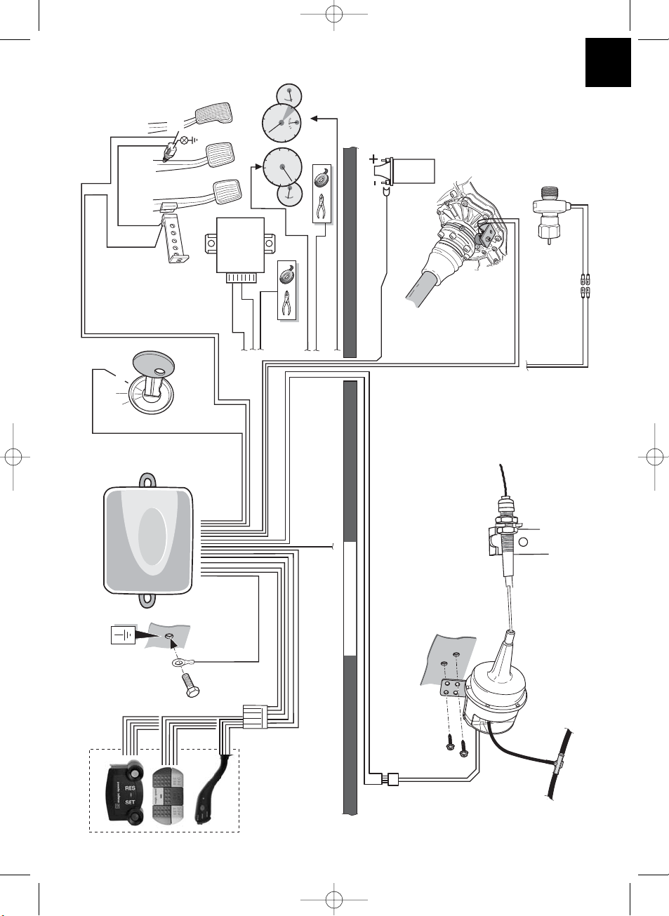
C
Command module
Bedienmodul
8-poliger
Stecker
8-Pin
connector
4-poliger Stecker/4-Pin connector
Vakuumservo/Actuator
Masse
Ground
Grün/Green
Orange/Orange
Motorraum
Engine compartment
Lila Kabel wird nicht bnötigt/
Purple wire not required
Acc.
Zündschloss
Ignition key
Braun/Weiß Brown/White
Braun/Brown
Kupplungsschalter
Clutch switch
Bremslicht-
schalter
Brake switch
+12 V
Geschwindigkeitssignal/
Road
speed
signal
Gelb/Yellow
Blau/Blue
SchwarzBlack
Optional S.P.G.
(speed pulse generator)
Tachowellengenerator
(optional)
Blau/Blue
Schwarz/Black
Drehzahl-
signal (RPM)
Engine RPM
signal
Original Engine
Control Unit
Motorsteuer-
gerät
Gelb/Yellow
Blau/Blue
Blau/Blue
Schwarz/Black
Gelb/Yellow
Schwarz/Black
+30
+15
Zündspule
Coil
Geschwindig-
keitssensor
(optional)
Optional
speed sensor
Elektronikmodul
Electronic module
Schutzwand/Fire wall
MS-400.qxd 24/06/03 15:10 Page 5
Page 6
6
D
ø 3 mm
10 mm
2 x
> 300 mm
1
2
MS-400.qxd 24/06/03 15:10 Page 6
Page 7
7
E
F
1
3
2
1
Gaspedal Arbeitsweg/
Throttle pedal stroke
> 38 mm
Vakuumservo
Arbeitsweg/
Actuator stroke
38 mm
MS-400.qxd 24/06/03 15:10 Page 7
Page 8
8
F
< 20°
2
3
4
MS-400.qxd 24/06/03 15:10 Page 8
Page 9
9
F
5
6
7
8
Schutzwand/
Fire wall
MS-400.qxd 24/06/03 15:10 Page 9
Page 10
10
G
H
ø 6 mm
Bedienmodul/
Command module
Doppelseitiges Klebeband/
Double adhesive tape
Armaturenbrett/
Dashboard
8-poliger Stecker
8-Pin connector
MS-400.qxd 24/06/03 15:10 Page 10
Page 11
11
H
23
4
Braun/Brown
Kupplung nicht betätigt/
Clutch not depressed
Kupplung betätigt/
Clutch depressed
Braun/Weiß
Brown/White
Kupplungsschalter/
Clutch switch
Bremslichtschalter/
Brake switch
+12 V
Max. 10 mm
Max. 20 mm
MS-400.qxd 24/06/03 15:10 Page 11
Page 12
12
I
12
3
Blau/Blue
Schwarz/Black
3-5 mm
MS-400.qxd 24/06/03 15:10 Page 12
Page 13
13
Inhaltsverzeichnis
Lesen Sie diese Bedienungsanleitung, bevor Sie das Zusatzgerät installieren.
Abbildungen zur Einbauanleitung . . . . . . . . . . . . . . . . . . . . . . . . . . . . . . . . . . . . . . . . 3-12
Inhaltsverzeichnis . . . . . . . . . . . . . . . . . . . . . . . . . . . . . . . . . . . . . . . . . . . . . . . . . . . . . 13
Hinweise zur Benutzung der Einbauanleitung. . . . . . . . . . . . . . . . . . . . . . . . . . . . . . . . . 13
Sicherheits- und Einbauhinweise . . . . . . . . . . . . . . . . . . . . . . . . . . . . . . . . . . . . . . . . . . 14
Lieferumfang . . . . . . . . . . . . . . . . . . . . . . . . . . . . . . . . . . . . . . . . . . . . . . . . . . . . . . . . . 16
Benötigte Werkzeuge. . . . . . . . . . . . . . . . . . . . . . . . . . . . . . . . . . . . . . . . . . . . . . . . . . . 17
Bedienmodul . . . . . . . . . . . . . . . . . . . . . . . . . . . . . . . . . . . . . . . . . . . . . . . . . . . . . . . . . 17
Vakuum-Servogerät. . . . . . . . . . . . . . . . . . . . . . . . . . . . . . . . . . . . . . . . . . . . . . . . . . . . 17
Unterdruckverbindung . . . . . . . . . . . . . . . . . . . . . . . . . . . . . . . . . . . . . . . . . . . . . . . . . . 18
Bowdenzugbefestigung . . . . . . . . . . . . . . . . . . . . . . . . . . . . . . . . . . . . . . . . . . . . . . . . . 18
Elektronikmodul. . . . . . . . . . . . . . . . . . . . . . . . . . . . . . . . . . . . . . . . . . . . . . . . . . . . . . . 19
Kabelbaum . . . . . . . . . . . . . . . . . . . . . . . . . . . . . . . . . . . . . . . . . . . . . . . . . . . . . . . . . . 19
Diagnosemodus . . . . . . . . . . . . . . . . . . . . . . . . . . . . . . . . . . . . . . . . . . . . . . . . . . . . . . 25
Sicherheitseinrichtungen . . . . . . . . . . . . . . . . . . . . . . . . . . . . . . . . . . . . . . . . . . . . . . . . 27
Einstell-/Lernmodus. . . . . . . . . . . . . . . . . . . . . . . . . . . . . . . . . . . . . . . . . . . . . . . . . . . . 29
Bedienung des Geschwindigkeitsreglers . . . . . . . . . . . . . . . . . . . . . . . . . . . . . . . . . . . . 33
Funktionstest . . . . . . . . . . . . . . . . . . . . . . . . . . . . . . . . . . . . . . . . . . . . . . . . . . . . . . . . 34
Fehlersuche und -beseitigung . . . . . . . . . . . . . . . . . . . . . . . . . . . . . . . . . . . . . . . . . . . . 35
Zubehör. . . . . . . . . . . . . . . . . . . . . . . . . . . . . . . . . . . . . . . . . . . . . . . . . . . . . . . . . . . . . 37
Einstellmodus . . . . . . . . . . . . . . . . . . . . . . . . . . . . . . . . . . . . . . . . . . . . . . . . . . . . . . . . 39
Entsorgungshinweis. . . . . . . . . . . . . . . . . . . . . . . . . . . . . . . . . . . . . . . . . . . . . . . . . . . . 40
Technische Daten . . . . . . . . . . . . . . . . . . . . . . . . . . . . . . . . . . . . . . . . . . . . . . . . . . . . . 40
Hinweise zur Benutzung der Einbauanleitung
Warnung! Sicherheitshinweis!
Nichtbeachtung kann zu Personen- oder Materialschäden führen.
Achtung! Sicherheitshinweis!
Nichtbeachtung führt zu Materialschäden und beeinträchtigt die Funktion des
Geschwindigkeitsreglers MS-400.
Die Raute kennzeichnet Einbauschritte, die Sie ausführen müssen.
Damit der Einbau ohne Schwierigkeiten stattfindet, diese Einbauanleitung und Bedienungsanleitung vor Beginn der Montage durchlesen. Sollte die Anleitung nicht alle Ihre
Fragen beantworten oder sollten Montageschritte nicht klar sein, fragen Sie bitte unbedingt unseren technischen Kundenservice.
WAECO International GmbH
D-48282 Emsdetten · Hollefeldstraße 63
Tel. +49 (0) 25 72/87 91 91 · Fax +49 (0) 25 72/87 93 91
www.waeco.de
◆
MS-400.qxd 24/06/03 15:10 Page 13
Page 14
14
Sicherheits- und Einbauhinweise
Warnung! Unzureichende Leitungsverbindungen können zur Folge haben, dass
durch Kurzschluss:
• Kabelbrände entstehen
• der Airbag ausgelöst wird
• elektronische Steuerungseinrichtungen beschädigt werden
• elektrische Funktionen (Blinker, Bremslicht, Hupe, Zündung, Licht) ausfallen
Beachten Sie deshalb folgende Hinweise:
Bei Arbeiten an den Leitungen des Fahrzeuges gelten folgende Klemmenbezeichnungen:
30 (Eingang von Batterie Plus direkt),
15 (Geschaltetes Plus, hinter Batterie)
31 (Rückleitung ab Batterie, Masse)
58 (Standlicht) (Rückfahrscheinwerfer)
Die sicherste Verbindungsart ist, die Kabelenden miteinander zu verlöten und anschließend zu isolieren.
Bei wieder lösbaren Verbindungen nur isolierte Kabelschuhe, Stecker und Flachsteckhülsen verwenden. Keine Lüsterklemmen verwenden.
Zum Verbinden der Kabel mit Kabelschuhen, Steckern oder Flachsteck-hülsen eine
Krimpzange verwenden.
Bei Kabelanschlüssen an 31 (Masse):
Das Kabel mit Kabelschuh und Zahnscheibe an eine fahrzeugeigene Masseschraube
schrauben oder mit Kabelschuh, Blechschraube und Zahnscheibe an das Karosserieblech
schrauben.
Auf gute Masseübertragung achten!
Warnung! Wegen Kurzschlussgefahr vor Arbeiten an der Fahrzeugelektrik
immer den Minuspol der Batterie abklemmen.
Bei Fahrzeugen mit Zusatzbatterie ebenfalls den Minuspol abklemmen.
Achtung! Beim Abklemmen des Minuspols der Batterie verlieren alle flüchtigen
Speicher der Komfort-Elektronik ihre gespeicherten Daten.
MS-400.qxd 24/06/03 15:10 Page 14
Page 15
15
MS-400.qxd 24/06/03 15:10 Page 15
Sicherheits- und Einbauhinweise
Folgende Daten müssen Sie je nach Fahrzeugausstattung neu eingeben:
Radiocode · Fahrzeuguhr · Zeitschaltuhr · Bordcomputer · Sitzposition
Hinweise zur Einstellung können Sie in der jeweiligen Bedienungsanleitung nachlesen.
Achtung! Zum Prüfen der Spannung in elektrischen Leitungen darf nur ein Voltmeter (siehe ✎ B 2) benutzt werden.
Achtung! Um Schäden zu vermeiden, auf ausreichenden Freiraum für den Bohreraustritt achten. Jede Bohrung entgraten und mit Rostschutzmittel behandeln.
Achtung! Beachten Sie beim Verlegen der elektrischen Anschlüsse, dass diese:
1. nicht stark geknickt und verdreht werden
2. nicht an Kanten scheuern
3. nicht ohne Schutz durch scharfkantige Durchführungen verlegt werden.
Achtung! Achten Sie darauf, dass der Fahrer zur Bedienung nicht durch das
Lenkrad greifen muss und dass Bauteile von MagicSpeed nicht im
Wirkungsbereich der Fahrzeugairbags und im Kopfaufschlagsbereich liegen.
WAECO International übernimmt keine Haftung für Schäden, aufgrund folgernder Punkte:
a) Montagefehler
b) Beschädigungen am System durch mechanische Einflüsse und Überspannungen
c) Veränderungen an MagicSpeed ohne ausdrücklicher Genehmigung von WAECO
International
d) Verwendung für andere als die in der Montageanleitung beschriebenen Zwecke.
Page 16

16
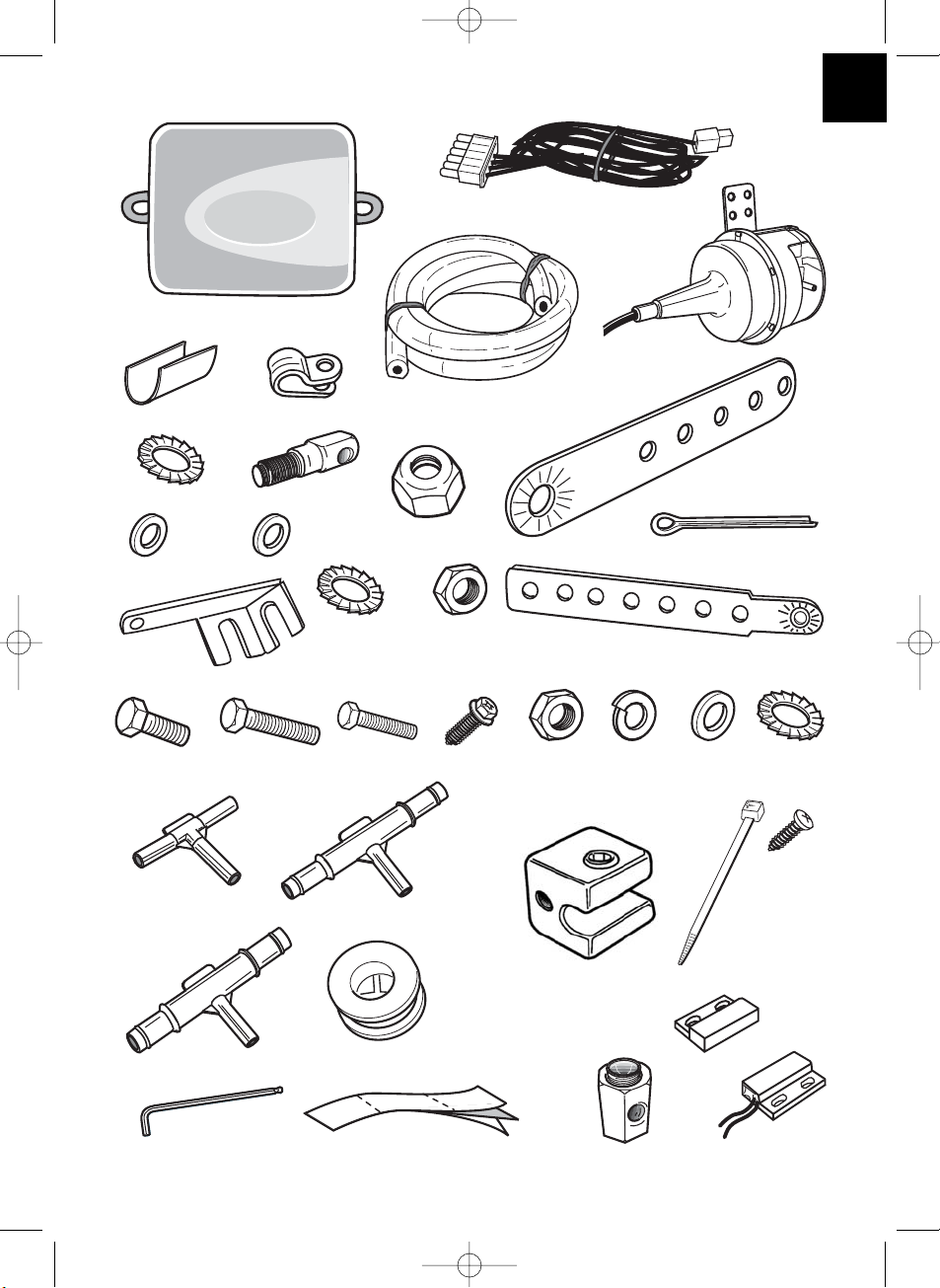
Lieferumfang
Artikel Teilenr. Stück Beschreibung
(siehe ✎ A 1) AS86040 1 Elektronikmodul
(siehe ✎ A 2) AS86020 1 Vakuum-Servogerät
(siehe ✎ A 3) PR9755A 1 Unterdruckleitung
(siehe ✎ A 4) WH58030 1 Kabelbaum
AS86030 1 Montagekit
(siehe ✎ A 5.1) 1 Zughebel
(siehe ✎ A 5.2) 3 Spleissschutz
(siehe ✎ A 5.3) 1 Bowdenzughalter
(siehe ✎ A 5.4) 1 Zahnscheibe M8
(siehe ✎ A 5.5) 1 Bolzen
(siehe ✎ A 5.6) 1 Selbsichernde Mutter M4
(siehe ✎ A 5.7) 1 Unterlegscheibe M4
(siehe ✎ A 5.8) 2 NylonunterlegscheibeM5
(siehe ✎ A 5.9) 1 Splint
(siehe ✎ A 5.10) 1 Montageblech
(siehe ✎ A 5.11) 1 Montagewinkel für Bowdenzug
(siehe ✎ A 5.12) 1 Federscheibe M6
(siehe ✎ A 5.13) 1 Mutter M6
(siehe ✎ A 5.14) 1 Maschinenschraube M6x12
(siehe ✎ A 5.15) 1 T-Stück 5 mm
(siehe ✎ A 5.16) 1 T-Stück 1/4" bis 5/16"
(siehe ✎ A 5.17) 1 T-Stück 3/8" bis 1/2"
(siehe ✎ A 5.18) 3 Maschinenschraube M6x15
(siehe ✎ A 5.19) 1 Maschinenschraube M6x12
(siehe ✎ A 5.20) 2 Gewindeschraube, schwarz
(siehe ✎ A 5.21) 3 Mutter M6
(siehe ✎ A 5.22) 3 Federscheibe M6
(siehe ✎ A 5.23) 2 Flachscheibe M6
(siehe ✎ A 5.24) 1 Spezial-ZahnscheibeM6
(siehe ✎ A 5.25) 1 Kabelklemme
(siehe ✎ A 5.26) 1 Imbusschraube M4x6
(siehe ✎ A 5.27) 1 Stopper
(siehe ✎ A 5.28) 1 Imbusschraube M4x4
(siehe ✎ A 5.29) 1 Imbusschraube M2
(siehe ✎ A 5.30) 1 Gummitülle
(siehe ✎ A 5.31) 10 Kabelbinder
(siehe ✎ A 5.32) 1 Doppelseitiges Klebeband
(siehe ✎ A 5.33) 2 Schraube 8x1/2
(siehe ✎ A 6) AS 40420 1 Kupplungsschalter
MS-400.qxd 24/06/03 15:10 Page 16
Page 17
17
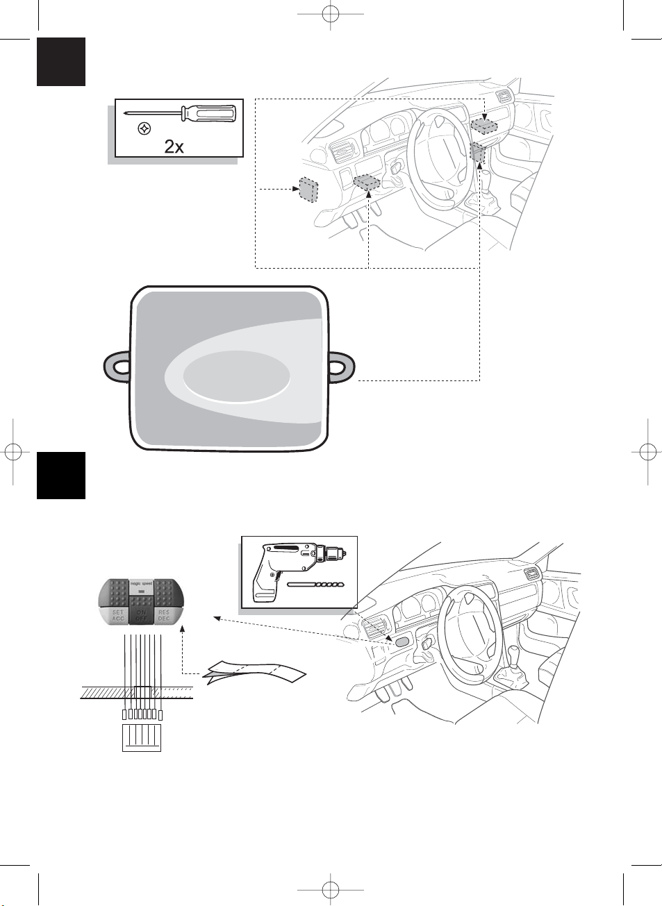
Vakuum-Servogerät
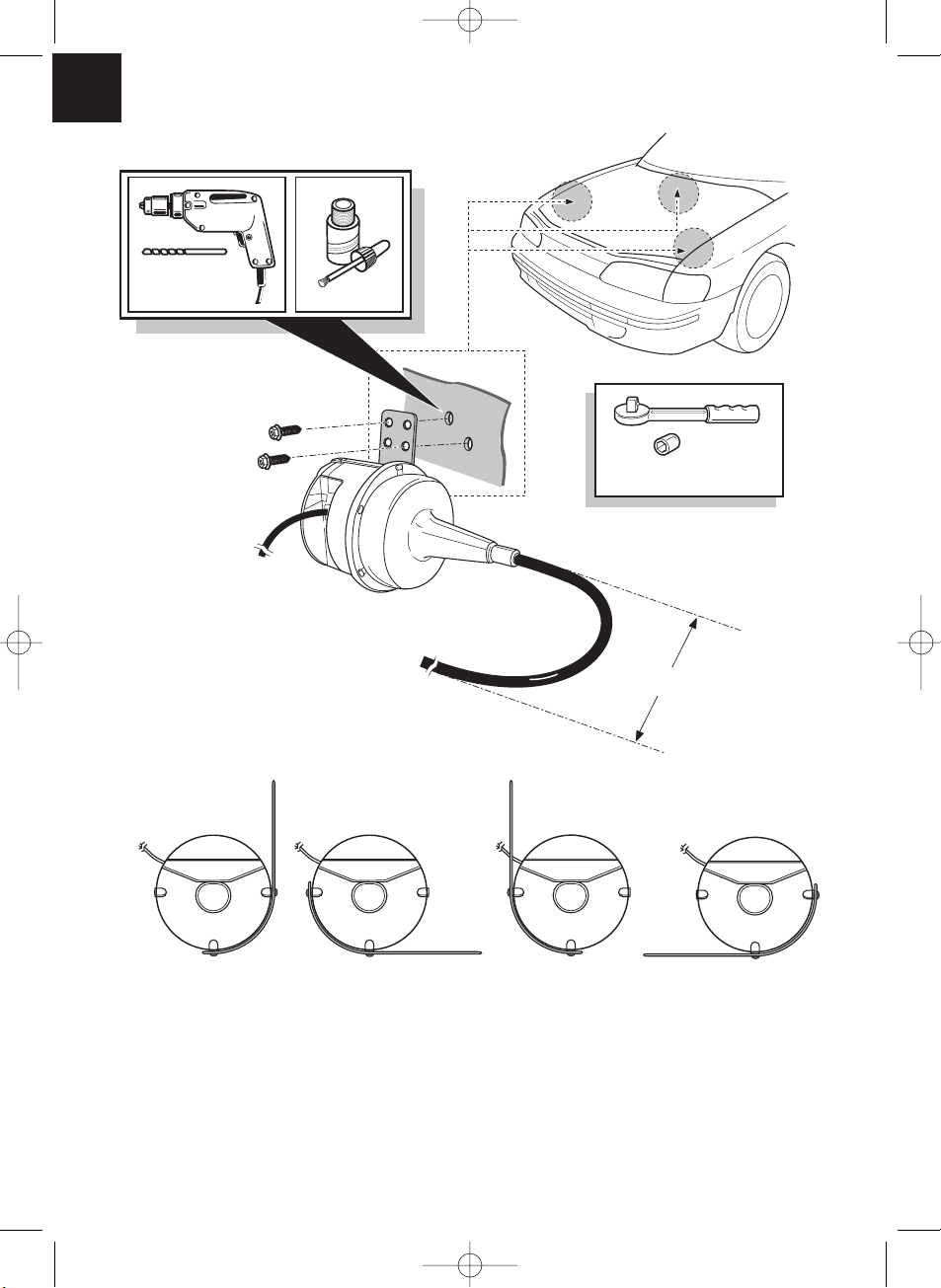
Das Vakuum-Servogerät sollte im Motorraum an der Spritzwand oder auf den Innenkotflügeln (siehe ✎ D 1) montiert werden. Wichtig ist, das Vakuum-Servogerät nicht in der
Nähe von Hitzequelle und mindestens 300 mm Entfernung von jeder Hochspannungsquelle wie Zündverteiler, Zündspule, Zündkabel oder Lichtmaschine zu montieren. Der
Bowdenzug des Vakuum-Servogerätes sollte in einem Bogen von mindestens 300 mm
an den Originalgaszug bzw. Gasgestänge herangeführt werden.
Vorsicht! Der Bowdenzug muss von rotierenden oder heißen Flächen bzw.
Teilen ferngehalten werden.
Das Montageblech des Vakuum-Servogerätes kann an 4 verschiedenen Positionen am
Vakuum-Servogerät befestigt werden, wodurch eine maximale Flexibilität bei der Montage
gewährleistet wird (siehe ✎ D 2).
Bedienmodul
Modul, siehe ✎ C
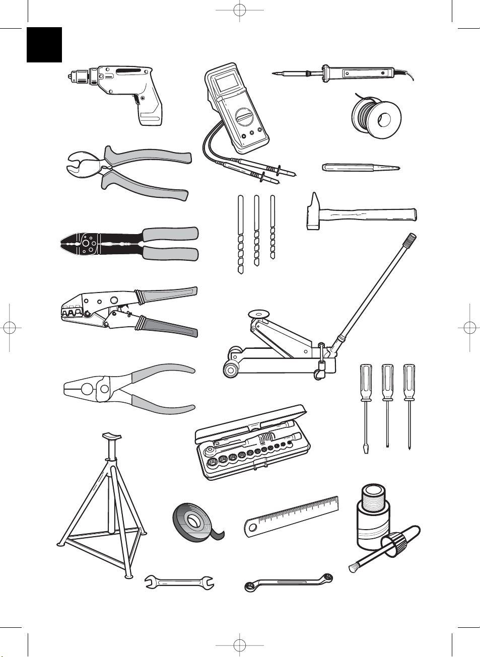
Benötigte Werkzeuge
Im Folgenden sind die für eine korrekte Montage des Tempomaten benötigten Werkzeuge
aufgelistet. Obwohl es möglich ist, dieses Gerät auch ohne einige der aufgelisteten Werkzeuge zu montieren, empfehlen wir Ihnen, diese Werkzeuge dennoch zur Hand zu haben.
Es wird dringend empfohlen, die Verbindungen zu löten, um eine haltbare Verbindung
sicherzustellen.
– Bohrmaschine (s. ✎ B 1) – Wagenheber (s. ✎ B 11)
– Voltmeter (s. ✎ B 2) – Schraubenziehersatz (s. ✎ B 12)
– Lötkolben und -material (s ✎ B 3) – Steckschlüsselsatz (s. ✎ B 13)
– Seitenchneider (s. ✎ B 4) – Achsmontageständer (s. ✎ B 14)
– Abisolierzange (s. ✎ B 5) – Isolierband (s. ✎ B 15)
– Krimpzange (s. ✎ B 6) – Messlineal (s. ✎ B 16)
– Zange (s. ✎ B 7) – Schraubenschlüssel (s. ✎ B 17)
– Bohrersatz (s. ✎ B 8) – Ringschlüsselsatz (s. ✎ B 18)
– Zentrierkörner (s. ✎ B 9) – Dichtungsmasse (s. ✎ B 19)
– Hammer (s. ✎ B 10)
MS-400.qxd 24/06/03 15:10 Page 17
Page 18
18
Unterdruckverbindung
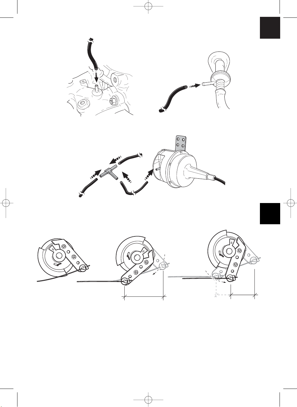
Wählen Sie eine gute, nicht eingeschränkte Unterdruckquelle zum Anschluss des Unterdruckschlauches an das Vakuum Servogerät. Die gebräuchlichste Quelle befindet sich
direkt am Motoransaugkrümmer (siehe ✎ E 1) oder zwischen Ansaugkrümmer und
Bremskraftverstärker (siehe ✎ E 2). Verwenden Sie keine Unterdrucksteuerleitungen
wie z. B. Unterdruckleitung vom Zündverteiler oder AGV-Unterdruckregler. Bei Fahrzeugen mit einer separaten Unterdruckpumpe empfiehlt sich der Anschluss zwischen
Pumpe und Rückschlagventil des Unterdruck-Bremskraftverstärkers.
Bowdenzugbefestigung
Vorsicht! Ihr Geschwindigkeitsregler ist zwar mit verschiedenen Sicherheitsmerkmalen ausgestattet, jedoch können diese ein Verdrehen oder Verklemmen
des Originalgaszuges bzw. Gasgestänge nicht verhindern. Überprüfen Sie den
originalen Gaszug bzw. das original Gasgestänge manuell und durch Treten des
Gaspedals, um sicherzustellen, dass das Gasgestänge bzw. der Gaszug korrekt
funktioniert und sich nicht verklemmt während der Betätigung.
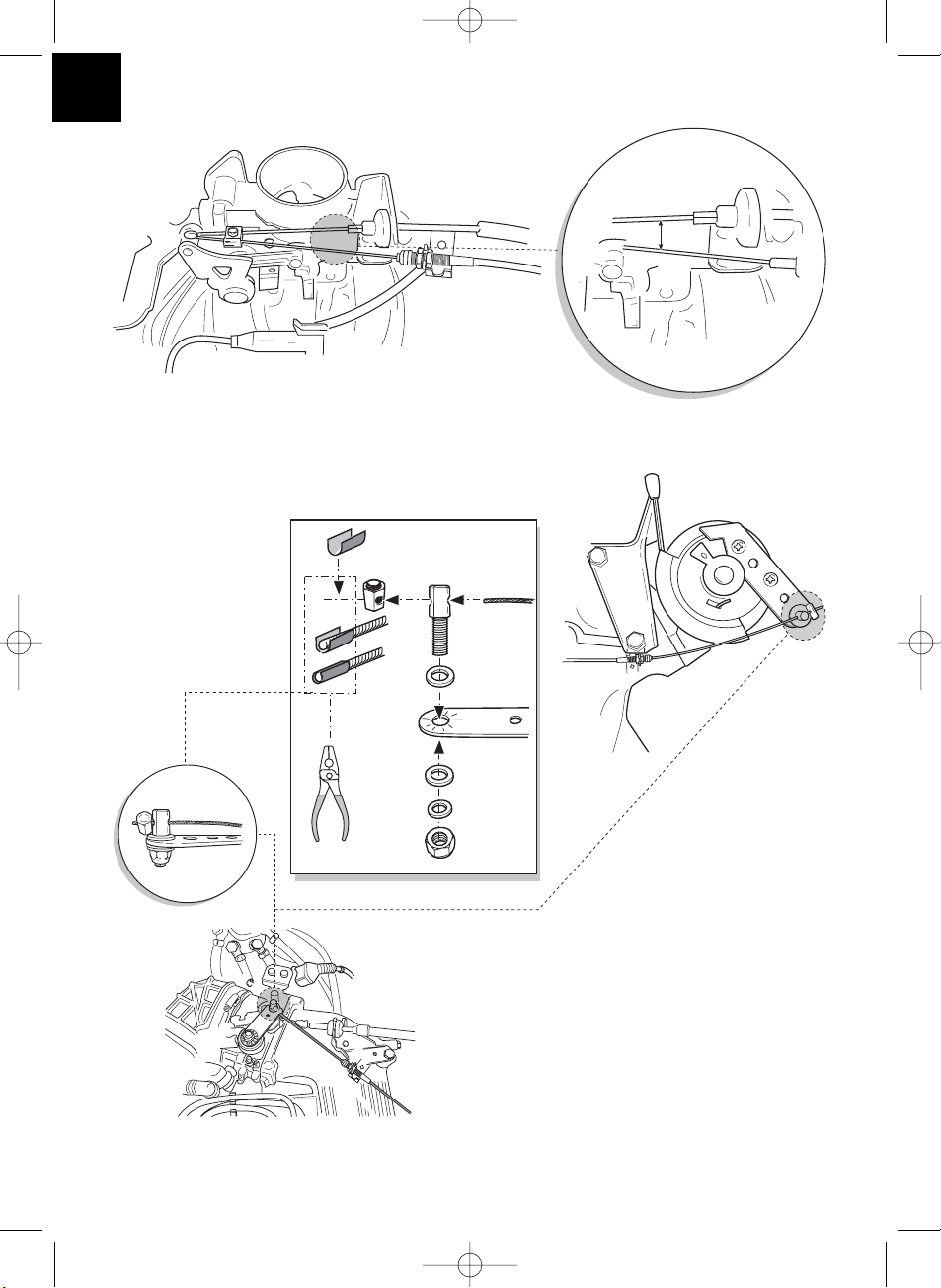
Möglichkeit 1
Montage an dem vorhandenen oder zusätzlich montierten Gashebel. Der Bowdenzug des
MS-400 wird hierbei über den drehbaren Bolzen befestigt. Wird das Gaspedal manuell
betätigt rutscht der Bowdenzug des MS-400 durch den Bolzen (siehe ✎ F 1, F 3, F 4).
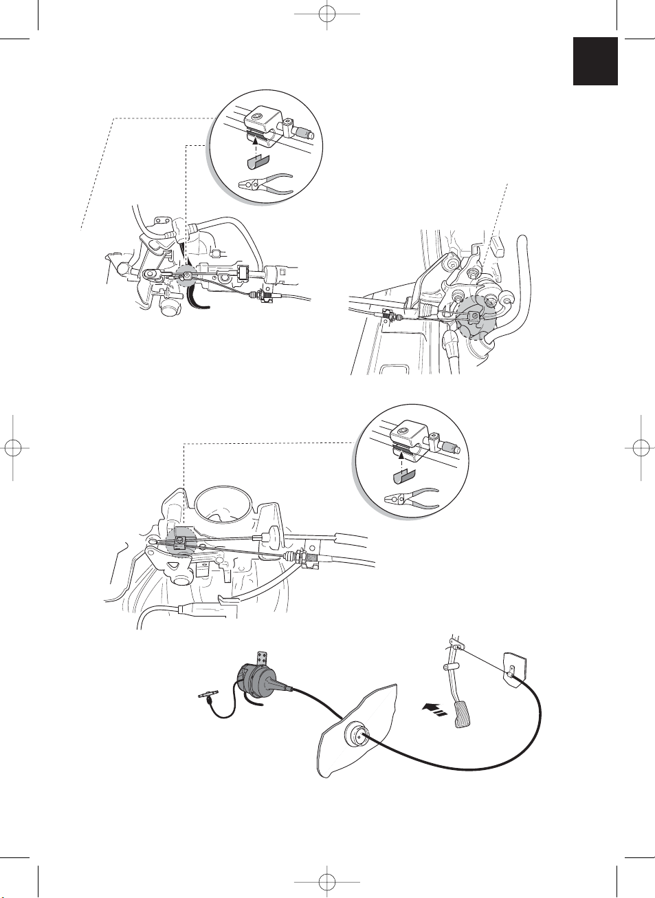
Möglichkeit 2
Montage an dem vorhandenen Bowdenzug.
Der Bowdenzug des MS-400 wird hierbei mit dem Klemmblock, der fest mit dem Gaszug
verbunden ist, befestigt (siehe ✎ F 5, F 6, F 7). Wird das Gaspedal manuell betätigt,
rutscht der Bowdenzug des MS-400 durch den Klemmblock.
Möglichkeit 3
Einige neuere Fahrzeuge haben keinen Gaszug mehr. Bei diesen Fahrzeugen ist eine
direkte Verbindung mit dem Gaspedal erforderlich. Der beste Montageort für das Vakuum
Servogerät ist trotzdem der Motorraum, da es sonst durch die arbeitenden Ventile im
Servo zu Geräusch Belästigungen kommen kann. Der Bowdenzug des MS-400 sollte
durch die Spritzwand in den Fahrgastraum geführt werden (siehe ✎ F 8).
MS-400.qxd 24/06/03 15:10 Page 18
Page 19
19
Elektronikmodul
Das Elektronikmodul sollte immer im Fahrgastraum des Fahrzeugs mit 4-mm-Metallschrauben oder dem gelieferten Doppelklebeband montiert werden. Vermeiden Sie Orte
mit großem Hitzeaufkommen, Feuchtigkeit und Hochspannungsführenden Bauteilen.
Bevorzugte Montageorte: Unter dem Armaturenbrett auf der Fahrerseite, hinter dem
Handschuhfach oder dem Trittschutz auf der Fahrer- oder Beifahrerseite (siehe ✎ G).
Montieren Sie das Elektronikmodul nicht im Motorraum. Für die Montage markieren
Sie die Löcher, Zentrierkörner und bohren zwei 3-mm-Löcher.
Überprüfen Sie vor dem Bohren immer die Austrittsseite auf freien Durchgang.
Installieren Sie das Elektronikmodul provisorisch an der gewählten Position.
Befestigen Sie das Elektronikmodul nicht, bevor Sie die Kabelführung festgelegt haben.
Nach Abschluss der Montage befestigen Sie das Modul an der gewählten Position.
Kabelbaum
Nachdem der Einbauort des Elektronikmoduls festgelegt wurde, kann der Kabelbaum des
Geschwindigkeitsreglers montiert werden.
Bedienmodul (siehe ✎ H 1)
Es stehen eine Reihe von Bedienmodulen für hohen Bedienkomfort bei jeder Anwendung
zur Verfügung.
Das Bedienmodul des Geschwindigkeitsreglers muss an einem Ort montiert werden,
wo eine sichere Arbeitsweise unter allen Umständen sichergestellt ist. Geeignete Orte
sind auf dem Armaturenbrett oder der Mittelkonsole, abhängig von der Formgebung
und Erreichbarkeit sowie dem Bedienmodul.
Nachdem Sie den geeigneten Ort für das Bedienmodul gewählt haben, muss ein 6 mm
großes Loch in der Nähe des Bedienmoduls gebohrt werden. Die Kabel des Bedienmoduls können jetzt durch dieses Loch zum Kabelbaum des Geschwindigkeitsreglers
geführt werden. Die Anschlusskabel des Bedienmoduls können in den Kompaktstecker
geschoben und in das 8-polige Leergehäuse eingesteckt werden. Stecken Sie den
montierten 8-poligen Kompaktstecker des Bedienteils mit dem 8-poligen Gegenstecker
vom Hauptkabelbaum zusammen.
MS-400.qxd 24/06/03 15:10 Page 19
Page 20
20
Kabelbaum
Infrarot-Bedienmodul und Steuersäulen-Bedienmodul:
Sowohl das Infrarot- als auch das Steuersäulen-Bedienmodul werden mit einer eigenen
Montageanleitung geliefert. Diese Anleitungen sind vor der Durchführung der Montage
sorgfältig zu lesen.
Vorsicht! Stellen Sie sicher, dass der Fahrer seine Hand zur Bedienung des
Moduls nicht durch das Lenkrad führen muss.
Grün/Rot, Schwarz, Rosa/Rot und Blau/Rot
Das 4-adrige Kabel für das Vakuum-Servogerät durch eine geeignete Durchführung
verlegen oder durch eine angefertigte Durchführung die mit der mitgelieferten Gummidichtung abgedichtet wird, in den Motorraum verlegen. Die 4 Kabel in das Steckerleergehäuse einstecken und mit dem Vakuum-Servo verbinden. Beachten Sie die Farbcodierung auf dem Steckerleergehäuse.
Oranges Kabel
Verbinden Sie das orange Kabel mit einem geschalteten Plus (Kl. 15). Vergewissern Sie
sich, dass das geschaltete Plus die volle Betriebsspannung (12 V) aufweist und dass bei
ausgeschalteter Zündung das Kabel spannungslos ist.
Hinweis! Überprüfen Sie mit einem Voltmeter, dass die von Ihnen gewählte
Einspeisung über die Zündung die volle Batteriespannung aufweist. Ein geeigneter Ort ist üblicherweise der Sicherungskasten. Es ist nicht empfehlenswert,
das orangefarbene Kabel mit der Spannungsversorgung des Fahrzeugzubehörs
(ACC) zu verbinden.
Grünes Kabel
Verbinden Sie das grüne Kabel an eine bestehende Fahrzeugmasse oder an den blanken
Metallmasseanschluss der Karosserie. Der gebräuchlichste Ort für eine zentrale Fahrzeugmasse ist die linke oder rechte A-Säule.
Braunes und braun-weißes Kabel
Verbinden Sie das braun und braun-weiße Kabel mit dem Bremslichtschalter (siehe ✎ H 2).
MS-400.qxd 24/06/03 15:10 Page 20
Page 21

21
Kabelbaum
Wenn mehr als zwei Kabel vom Bremslichtschalter ausgehen, benutzen Sie ein Voltmeter,
um die zwei benötigten Kabel zu identifizieren. Eines der zwei original Kabel am Bremslichtschalter sollte ein Dauerplus (Kl. 30, 12 V) bzw. ein geschaltetes Plus (Kl. 15) haben.
An dem zweiten original Kabel sollte bei betätigter Bremse eine Spannung von +12 V
anliegen. Sobald die Bremse losgelassen wird, darf an dem Kabel keine Spannung mehr
anliegen.
Sollten Sie am Bremslichtschalter keine vollen +12 V messen können, kann es sein, dass
Ihr Fahrzeug mit einem digitalen Bremssystem ausgerüstet ist. In diesem Fall müssen die
braunen Kabel wie folgt angeschlossen werden:
Das braun-weiße Kabel schließen sie an einem abgesicherten geschalteten Plus (Kl. 15)
an.
Das braune Kabel schließen sie an der original Leitung an, die zu den Bremsleuchten
führt. An diesem Kabel liegen bei betätigter Bremse +12 V an und bei gelöster Bremse
0 V. Möglicher Fundort für diese Kabel ist direkt an den Rückleuchten oder im Kabelstrang zum Fahrzeugheck.
Gelbes und blaues Signalkabel
(Anschluss des Geschwindigkeits- bzw. Drehzahlsignals)
Es gibt zwei verschiedene Möglichkeiten, ein Referenzsignal für den Geschwindigkeitsregler abzugreifen:
1. Geschwindigkeitssignal
Das Geschwindigkeitssignal dient zur tatsächlichen Angabe der Fahrgeschwindigkeit.
Dieser Signaltyp soll stets bei Fahrzeugen mit Automatikgetriebe eingesetzt werden,
eignet sich aber auch für Fahrzeuge mit manuellem Schaltgetriebe, wobei in diesem
Falle jedoch eine Abschaltung installiert werden muss, die verhindert, dass der Motor
überdrehen kann (siehe Seite 23).
2. Motordrehzahl (UPM)
Das Motordrehzahlsignal dient zur Angabe der Motordrehzahl (UPM). Die Fahrzeuggeschwindigkeit ist hierbei solange abhängig von der Motordrehzahl, wie sich das Fahrzeug
im selben Gang befindet. Das Motordrehzahlsignal eignet sich nur für Fahrzeuge mit
manuellem Schaltgetriebe. In diesem Falle ist jedoch wiederum eine Abschaltung zu
installieren, die verhindert, dass der Motor überdrehen kann (siehe Seite 24).
MS-400.qxd 24/06/03 15:10 Page 21
Page 22

22
Kabelbaum
Der Geschwindigkeitsregler ist mit zwei Kabeln ausgestattet, die zur Signalerfassung eingesetzt werden können.
1. Blaues Kabel
Zur Erfassung des Geschwindigkeitssignals und Drehzahlsignals mit einer Spannung
zwischen 1,5 Volt und 24 Volt und einer Frequenz zwischen 6 Hz und 8,5 kHz. Das blaue
Kabel sollte für sämtliche Signale eingesetzt werden, die auf den Bereich zwischen den
zwei vorgenannten Parametern zutreffen, d. h. sowohl für das Geschwindigkeitssignal als
auch für die Motordrehzahl.
2. Gelbes Kabel
Dient nur zur Erfassung des Drehzahlsignals mit einer Spannung zwischen 6 Volt und
250 Volt und einer Frequenz zwischen 6 Hz und 488 Hz.
Das gelbe Kabel sollte ausschließlich zur Erfassung von Drehzahlsignalen mit einer
Spannung von > 20 Volt eingesetzt werden. Ansonsten sollte das gelbe Kabel nur in
denjenigen Fällen bzw. Applikationen zum Einsatz kommen, in denen auch ein Motorüberdrehungsschutz erforderlich ist oder das Drehzahlsignal sich in einem Bereich
zwischen 6 und 250 Volt bewegt.
Motorüberdrehungsschutz
Wird ein Geschwindigkeitssignal als Signalquelle bei Fahrzeugen mit manuellem Schaltgetriebe eingesetzt, so muss auch ein Motorüberdrehungsschutz vorhanden sein, um
eine Beschädigung des Motors zu verhindern. Wird die Kupplung getreten, während der
Geschwindigkeitsregler aktiviert ist, muss sich der Geschwindigkeitsregler automatisch
ausschalten, da es ansonsten zu Schäden an dem Fahrzeugmotor kommen kann.
Es gibt zwei Arten des Motorüberdrehungsschutzes:
1. Wird das blaue Kabel zur Übertragung des Geschwindigkeitssignals eingesetzt, so
kann das gelbe Kabel zur Übertragung der Motordrehzahl angeschlossen werden,
um so den erforderlichen Motorschutz zu gewährleisten. Siehe hierzu auch den
Absatz zur Ermittlung von Geschwindigkeitsimpulssignalen.
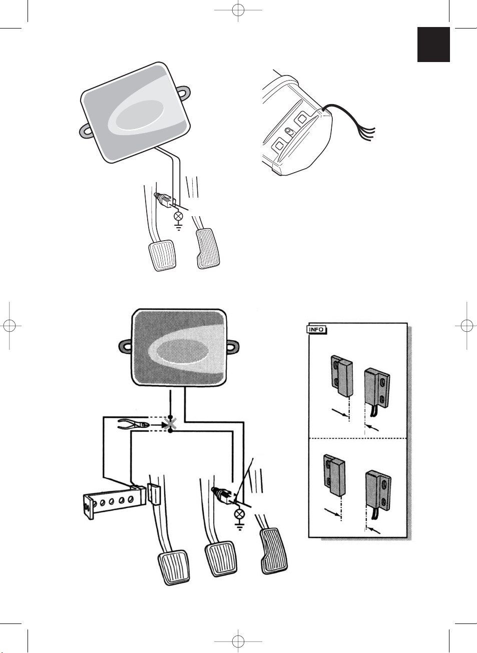
2. Es kann auch ein Kupplungsschalter verwendet werden, wenn kein entsprechendes
Drehzahlsignal vorhanden ist. Der Kupplungsschalter sollte am Kupplungspedal
montiert werden, so dass sich der Geschwindigkeitsregler automatisch beim Betätigen
des Kupplungspedals ausschaltet (siehe ✎ H 4).
MS-400.qxd 24/06/03 15:10 Page 22
Page 23

23
Kabelbaum
Der Signalabgriff ist immer von dem verwendeten Getriebe im Fahrzeug abhängig.
Fahrzeuge mit Automatikgetriebe
Es sollte das blaue Kabel verwendet werden, welches hierbei für die Übertragung des
Geschwindigkeitssignals anzuschließen ist. Es darf keinesfalls ein Drehzahlsignal ver-
wendet werden. Bei Fahrzeugen mit Automatikgetriebe ist ansonsten kein zusätzlicher
Überdrehungsschutz erforderlich. Siehe hierzu auch den Absatz über die Ermittlung von
adäquaten Geschwindigkeitssignalen.
Wird am Fahrzeug kein entsprechend geeignetes Geschwindigkeitssignal gefunden, so
kann der optional erhältliche Magnetsensorbausatz bzw. der optional erhältliche Geschwindigkeitsimpulsgeber montiert werden (siehe optional erhältliches Zubehör s. 37 ).
Fahrzeuge mit Handschaltgetriebe
Die beste Lösung bei Fahrzeugen mit Handschaltgetrieben ist die Belegung des blauen
Kabels mit dem Geschwindigkeitssignal und die Verwendung des gelben Kabels als
Überdrehungsschutz mittels Drehzahlsignal oder Kupplungsschalter. Siehe hierzu auch
den Absatz über die Ermittlung von adäquaten Geschwindigkeitsimpulssignalen. Wird
kein entsprechendes Geschwindigkeitssignal gefunden, so kann der optional erhältliche
Magnetsensorbausatz bzw. der optional erhältliche Geschwindigkeitsimpulsgeber
montiert werden. Wird am Fahrzeug kein Geschwindigkeitssignal gefunden, so kann das
blaue Kabel mit dem Drehzahlsignal belegt werden, oder aber das gelbe Kabel kann auf
der negativen Polseite der Zündspule (Kl. 1) angeschlossen werden. Bei dieser Lösung
ist kein zusätzlicher Überdrehungsschutz mehr erforderlich, da hierbei die Motordrehzahl
vom Geschwindigkeitsregler überwacht wird. Bei Einsatz eines Drehzahlsignals hängt
die Mindestgeschwindigkeit zur Aktivierung des Geschwindigkeitsreglers vom Gang ab,
in dem sich das Fahrzeug zu dem Zeitpunkt befindet.
Abgriff des Geschwindigkeits- bzw. Drehzahlsignals
Es gibt verschiedene Möglichkeiten, das Drehzahl- bzw. Geschwindigkeitssignal für
den Geschwindigkeitsregler abzugreifen. In dem nachfolgenden Abschnitt finden Sie
verschiedene Möglichkeiten das Signal zu identifizieren.
MS-400.qxd 24/06/03 15:10 Page 23
Page 24

24
Kabelbaum
Geschwindigkeitsignale
Bei Fahrzeugen mit manuellen Schaltgetriebe muss zwingend ein Motorüberdrehungsschutz installiert werden.
a. Über die Motorsteuerung übertragenes Geschwindigkeitssignal.
Spannung: zwischen 1,5 und 24 Volt, Frequenz: zwischen 6 Hz und 8,5 kHz.
b. Elektronischer Drehzahlmesser – auf der Rückseite der Instrumentenbaugruppe oder
als Teilsatz der Instrumentenbaugruppe.
Spannung: zwischen 1,5 und 24 Volt, Frequenz: zwischen 6 Hz und 8,5 kHz.
c. Geschwindigkeitssensor – ist am Getriebe installiert und verfügt im Allgemeinen über
3 Kabel.
Spannung: zwischen 1,5 und 24 Volt, Frequenz: zwischen 6 Hz und 8,5 kHz.
d. Autoradio – in der Nähe des Radios, falls der Wagen eine ISO-Verbindung hat. Der
Geschwindigkeitsimpuls ist hierbei in Kammer 3, Kontaktstift 1 oder 5.
Spannung: zwischen 1,5 und 24 Volt, Frequenz: zwischen 6 Hz und 8,5 kHz.
Motordrehzahlsignale
a. Über die Motorsteuerung übertragenes Motordrehzahlsignal.
1,5-24 Volt.
b. Elektronischer Drehzahlmesser – auf der Rückseite der Instrumentenbaugruppe.
Spannung: zwischen 1,5 und 24 Volt, Frequenz: zwischen 6 Hz und 488 Hz.
c. Anschlussklemme am W+ Pol der Lichtmaschine, an einigen Lichtmaschinen befindet
sich eine zusätzliche Anschlussklemme. Diese Anschlussklemme ist bei manchen Fahrzeugen nicht belegt, wodurch eine Verbindung zur Lichtmaschine erforderlich ist.
Spannung: 6-250 Volt; Frequenz: zwischen 6 Hz und 488 Hz.
d. Negative Polseite der Zündungsspule (Kl. 1) – bei dieser Art von Verbindung muss das
gelbe Kabel verwendet werden.
Spannung: 6-250 Volt; Frequenz: zwischen 6 Hz und 488 Hz.
Zum Überprüfen des gewählten Signals sollten Sie ein Voltmeter verwenden und folgendermaßen vorgehen: Verbinden Sie die rote Leitung des Voltmeters mit dem von Ihnen
gewählten Geschwindigkeitssignal, und die schwarze Leitung des Voltmeters mit der
Fahrzeugmasse. Fahren Sie nun das Fahrzeug mit der niedrigsten Geschwindigkeit,
bei der der Geschwindigkeitsregler aktiviert werden kann, und messen Sie die Effektivspannung des Signals. Beachten Sie, dass alle digitalen Voltmeter die Effektivspannung
messen, wenn sie sich im Wechselspannungsbereich befinden.
MS-400.qxd 24/06/03 15:10 Page 24
Page 25

25
Diagnosemodus
Der Geschwindigkeitsregler hat einen Selbstdiagnosemodus. Die Selbstdiagnose ist
in drei Bereiche aufgeteilt A, B und C zum Test aller Elemente und Funktionen des Geschwindigkeitsreglers. Bevor Sie die Selbstdiagnose starten, prüfen Sie nochmals alle
Kabelverbindungen auf Ihren korrekten Anschluss.
Schalten Sie das Schaltgetriebe in den Leerlauf bzw. das Automatikgetriebe in die Parkstellung und ziehen Sie die Handbremse an.
Zum Starten der Diagnosefunktion mit akustischer Anzeige schalten Sie bei gedrückter
SET-Taste die Zündung EIN. Sie erhalten bei eingeschalteter Zündung und gedrückter
SET-Taste ein akustisches Quittiersignal, solange wie Sie die SET-Taste gedrückt halten.
Sollten Sie ein weiteres akustisches Signal innerhalb einer Sekunde erhalten, nachdem
Sie die SET-Taste losgelassen haben, ist ein Steuereingang geschaltet, z. B. der Kupplungsschalter. Überprüfen Sie erneut die Kabelverbindungen.
Diagnosemodus A
Prüfung der elektronischen Bauteile und der elektrischen Anschlüsse
Die LED im Elektronikmodul und der integrierte Summer zeigen parallel die korrekten
Funktionen der elektrischen Verkabelung und der Bauteile an.
Bei einer nachträglichen Prüfung der Bauteile ist es nicht zwingend notwendig, das
Steuergerät freizulegen, da die akustischen Signale zu den optischen Signalen parallel
sind.
Sie erhalten über die LED bzw. den Summer eine Bestätigung beim Betätigen bzw. beim
Anliegen von folgenden Signalen:
SET-Taste
RES-Taste
Bremse
Kupplungsschalter
Geschwindigkeitssignal im Lernmodus
Drehzahlsignal im Lernmodus
Das akustische und optische Signal wird maximal pro Eingang für 10 Sekunden ausgegeben, um sicherzustellen, dass weitere Meldungen nicht unterdrückt werden. Sollten
Sie beim Betätigen einer der o. g. Funktionen kein akustisches bzw. optisches Signal
erhalten, so müssen Sie die elektrische Verkabelung überprüfen.
MS-400.qxd 24/06/03 15:10 Page 25
Page 26
26
Diagnosemodus
Diagnosemodus B
Nach erfolgreichem Abschluss des Testes A können Sie mit dem Test B fortfahren. Mit
diesem Diagnosemodus können Sie die Funktion des Servos testen. Schalten Sie das
Schaltgetriebe in den Leerlauf bzw. das Automatikgetriebe in die Parkstellung und ziehen
Sie die Handbremse an. Starten Sie den Motor bei gedrückter SET-Taste. Wenn der Motor
läuft, lassen Sie die SET-Taste wieder los. Schalten Sie nun den Geschwindigkeitsregler
mit der ON/OFF-Taste ein. Die LED im Steuergerät leuchtet auf. Drücken Sie die SETTaste und halten Sie sie gedrückt. Die Motordrehzahl muss langsam ansteigen (Achtung:
lassen Sie nicht den Motor überdrehen). Drücken Sie die RES-Taste und halten Sie sie
gedrückt. Die Motordrehzahl muss langsam abfallen. Durch Betätigen der Bremse oder
Kupplung bzw. durch Betätigen des ON/OFF-Schalters muss die Motordrehzahl wieder
auf die Leerlaufdrehzahl abfallen. Zum Verlassen des Diagnosemodus schalten Sie die
Zündung aus.
Diagnosemodus C
Der Diagnosemodus C dient zur Überprüfung des Geschwindigkeitssignals bzw. des
Drehzahlsignals. Starten Sie den Motor bei gedrückter SET-Taste. Wenn der Motor läuft,
lassen Sie die SET-Taste wieder los. Fahren Sie ca. 50 km/h mit Ihrem Fahrzeug. Schalten
Sie den Geschwindigkeitsregler über die On/Off-Taste am Bedienteil ein. Die LED im
Steuergerät sollte jetzt ca. einmal pro Sekunde blinken und Sie sollten ein akustisches
Signal ca. einmal pro Sekunde erhalten. Sollte dies nicht der Fall sein, führen Sie das
Einstell- und Lernprogramm aus. Zum Verlassen des Diagnosemodus schalten Sie bei
Stillstand des Fahrzeuges die Zündung ab.
Anmerkung! Die Diagnosemodi dienen zur Überprüfung aller Bauteile und
Funktionen des Geschwindigkeitsreglers. Der Geschwindigkeitsregler verwendet
ein intern erzeugtes Referenzsignal zum Test des Servos im Diagnosemodus B.
Falls der Geschwindigkeitsregler auch nach erfolgreichem Abschluss des Testes
B sich nicht korrekt in Funktion setzen lässt, so liegt das Problem in der Regel
am Abgriff des Geschwindigkeitssignals.
MS-400.qxd 24/06/03 15:10 Page 26
Page 27
27
Sicherheitseinrichtungen
Der Geschwindigkeitsregler ist mit zahlreichen Sicherheitseinrichtungen ausgestattet, die
den Geschwindigkeitsregler ausschalten, falls eine oder mehrere nachfolgend genannten
Situationen eintreten sollten:
1. Beim Durchtreten des Bremspedals,
2. beim Drücken der AUS-Taste am Steuermodul,
3. beim Überdrehen des Motors,
4. beim Abbremsen auf 50% der eingestellten Geschwindigkeit,
5. beim Beschleunigen auf 150% der eingestellten Geschwindigkeit,
6. beim Ausschalten der Zündung.
Der Geschwindigkeitsregler schaltet auch ab, falls Störungen im Bereich des Bremslichts
vorliegen wie z. b. defekte Bremslichter, eine defekte Sicherung oder eine gelöste Verbindung im Bereich des Bremslichtschalters.
Um einen sicheren und wirtschaftlichen Betrieb zu gewährleisten, sollten Sie den Tempomaten NIEMALS bei Staus oder auf nassen, rutschigen Straßen einsetzen.
Achtung! Der Geschwindigkeitsregler schaltet auch ab, falls Störungen im
Bereich des Bremslichts vorliegen wie z. B. defekte Bremslichter, eine defekte
Sicherung oder eine gelöste Verbindung im Bereich des Bremslichtschalters.
Achtung! Der Geschwindigkeitsregler verfügt zwar über eine Anzahl von Sicherheitseinrichtungen, doch es ist keine davon in der Lage, ein Verdrehen oder
Verklemmen des Bowdenzugs zu verhindern. Deshalb alles zweimal prüfen!
MS-400.qxd 24/06/03 15:10 Page 27
Page 28

28
Einstell-/Lernmodus
Mit dem Einstell- und Lernmodus können die wichtigsten Parameter des Geschwindigkeitsreglers für nahezu jedes Fahrzeug optimal eingestellt werden.
Mit den drei Einstell- und Lernmodi wird das Geschwindigkeits- bzw. Drehzahlsignal
(PPM), die Empfindlichkeit der Übernahme (INIT-Modus) und die Regelempfindlichkeit
(GAIN-Modus) eingestellt.
Das Einstellen der Grundparameter kann während der Fahrt durchgeführt werden. Dadurch sind Sie in der Lage, die Feineinstellung der Regelpararmeter individuell einzustellen und somit eine genaue Einstellung zu erreichen. Diese Einstellungen können
durchgeführt werden, ohne dass das Steuergerät ausgebaut werden muss, um den
Zugang zu den Schaltern für Sondereinstellungen zu ermöglichen.
Die Einstellungen bzw. Justage erfolgen elektronisch. Die eingestellten Parameter werden
im Elektronikmodul fest gespeichert bis das SET-UP-Programm erneut gestartet wird.
1. Starten des SET-UP-Modus
Zum Starten des SET-UP-Programms gehen Sie folgendermaßen vor:
Schalten Sie die Zündung EIN und Aus, starten Sie das Fahrzeug, betätigen Sie die
Bremse und halten Sie die Bremse für eine Minute gedrückt. Während Sie die Bremse
betätigen drücken Sie die SET-Taste viermal kurz hintereinander. Als Bestätigung erhalten
Sie 4 hohe akustische Signale. Zum Starten eines der unten genannten Einstell- und
Lernmodi müssen Sie immer die o. g. Prozedur starten.
2. Automatikmodus
Im Automatikmodus werden alle drei Parameter (PPM, GAI und INIT) automatisch auf Ihr
Fahrzeug abgestimmt. Im Anschluss des Automatikmodus können Sie alle drei Parameter
noch fein anpassen.
Um in den Automatikmodus zu gelangen, nachdem Sie die unter Punkt 1 aufgeführten
Schritte ausgeführt haben, betätigen Sie die Bremse und drücken Sie bei betätigter
Bremse die RES-Taste. Als Bestätigung erhalten sie ein tiefes akustisches Signal. Lösen
Sie die Bremse. Sie erhalten zur Bestätigung ein hohes akustisches Signal. Sollten Sie
mehr als ein akustisches Signal erhalten, wiederholen Sie den Vorgang.
Fahren Sie mit Ihrem Fahrzeug eine Geschwindigkeit von 70 km/h.
Drücken Sie die SET-Taste für die blaue Leitung als Signal-Eingang oder drücken Sie die
RES-Taste für die gelbe Leitung als Signal-Eingang.
MS-400.qxd 24/06/03 15:10 Page 28
Page 29

29
Einstell-/Lernmodus
Der Geschwindigkeitsregler schaltet sich sofort ein, nachdem Sie die SET- bzw. RESTaste gedrückt haben und schaltet in den INIT-Modus. Sie können in diesem Modus
das Ansprechverhalten optimieren und so den Freilauf des Bowdenzugs vom Servo ausgleichen. Sollte der Geschwindigkeitsregler zu träge die Geschwindigkeit übernommen
haben, drücken Sie die SET-Taste um den Wert zu erhöhen.
Hat der Geschwindigkeitsregler die Geschwindigkeit zu ruckartig übernommen, so dass
er übersteuert, drücken Sie die RES-Taste. Als Bestätigung für jeden Tastendruck auf die
SET- bzw. RES-Taste erhalten Sie ein akustisches Signal.
Zum Speichern der eingestellten Werte (PPM, INIT und GAIN) betätigen Sie die Bremse.
Sie können nun erneut das Programm aufrufen, indem Sie die RES-Taste bei betätigter
Bremse drücken. Zur Bestätigung erhalten Sie ein tiefes akustisches Signal. Lösen Sie
die Bremse. Nach dem Lösen der Bremse erhalten Sie ein hohes akustisches Signal zur
Bestätigung. Beginnen Sie das Programm von vorne, indem Sie die SET- bzw. RES-Taste
drücken, je nach Signalquelle. Zum Verlassen des SET-UP-Programms stoppen Sie Ihr
Fahrzeug und drücken viermal bei betätigter Bremse die SET-Taste.
Im Normalfall sollte Ihr Geschwindigkeitsregler jetzt optimal für Ihr Fahrzeug eingestellt
sein.
3. PPM Einstellung
Sollten Sie mit dem Regelbereich des Geschwindigkeitsreglers nicht zufrieden sein,
können Sie die PPM-Einstellung manuell einstellen.
Um in den PPM-Einstellmodus zu gelangen, führen Sie erst den Start des SET-UPProgramms aus.
Drücken Sie nun zweimal die RES-Taste bei betätigter Bremse. Pro Tastendruck erhalten
Sie ein tiefes akustisches Signal. Lösen Sie die Bremse. Nach dem Lösen der Bremse
erhalten Sie zur Bestätigung zwei hohe akustische Signale. Falls Sie nicht zwei hohe
akustische Signale erhalten, führen Sie die o. g. Schritte erneut aus.
Zum Einstellen des PPM-Wertes fahren Sie mit Ihrem Fahrzeug eine Geschwindigkeit von
ca. 35-40 km/h. Drücken Sie nun die SET-Taste für das blaue Kabel als Signaleingang
bzw. die RES Taste für die gelbe Leitung als Signaleingang. Der Geschwindigkeitsregler
schaltet sich sofort ein, nachdem Sie die SET- bzw. RES-Taste gedrückt haben und
schaltet in den Regelmodus. Zum Speichern der eingestellten Werte (PPM) betätigen
Sie die Bremse.
MS-400.qxd 24/06/03 15:10 Page 29
Page 30

30
Einstell-/Lernmodus
Zum Verlassen des SET-UP-Programms stoppen Sie Ihr Fahrzeug und drücken viermal
bei betätigter Bremse die SET-Taste.
Bei jeder Änderung der PPM-Einstellung werden sämtliche vorhergehenden INIT-Einstellungen samt den werkseitig eingestellten Sollwerten überschrieben, die GAIN-Einstellung bleibt jedoch unverändert.
Sollte der Geschwindigkeitsregler jetzt träge oder zu ruckartig die Geschwindigkeit
übernehmen, so muss die INIT-Einstellung durchgeführt werden. Sollte der Geschwindigkeitsregler im Regelbetrieb zu träge oder ruckartig arbeiten, muss die GAIN-Einstellung
manuell durchgeführt werden.
Sollte es der Fall ist, dass der Geschwindigkeitsregler im Regelbetrieb zu träge
oder ruckartig arbeitet, muss die GAIN-Einstellung manuell durchgeführt werden.
4. INIT-Modus
Im INIT-Modus können Sie die Empfindlichkeit der Geschwindigkeitsübernahme einstellen.
Falls der Geschwindigkeitsregler zu träge die Geschwindigkeit übernimmt, muss der
INIT-Wert erhöht werden. Falls die Geschwindigkeit zu ruckartig übernommen wird,
muss der INIT-Wert verringert werden.
Um in den INIT-Einstellmodus zu gelangen, führen Sie erst den Start des SET-UPProgramms aus.
Drücken Sie dreimal die RES-Taste bei betätigter Bremse. Pro Tastendruck erhalten
Sie ein tiefes akustisches Signal. Lösen Sie die Bremse. Nach dem Lösen der Bremse
erhalten Sie zur Bestätigung drei hohe akustische Signale. Falls Sie nicht drei hohe
akustische Signale erhalten, führen Sie die o. g. Schritte erneut aus.
Fahren Sie mit dem Geschwindigkeitsregler in einer beliebigen Geschwindigkeit, die
oberhalb der Mindest-Geschwindigkeit (40 km/h) liegt. Drücken Sie jetzt die SET-Taste
so lange, bis Sie merken, dass der Geschwindigkeitsregler die gefahrene Geschwindigkeit übernimmt. Schalten Sie den Geschwindigkeitsregler durch Betätigen der Bremse
ab. Drücken Sie erneut die SET-Taste, der Geschwindigkeitsregler sollte jetzt die Geschwindigkeit sanft übernehmen. Sollte dies nicht der Fall sein, können Sie mittels der
SET-Taste den INIT-Wert erhöhen und mittels der RES-Taste den Wert verringern. Für
jeden Tastendruck erhalten Sie ein akustisches Signal.
MS-400.qxd 24/06/03 15:10 Page 30
Page 31

31
Einstell-/Lernmodus
Achung! Die normalen AUF- und AB–Funktionen der SET-Taste und RES-Taste
sind in dieser Betriebsart gesperrt, so dass diese Tasten zur Eingabe von Einstellungen genutzt werden können.
Zum Speichern der eingestellten Werte (PPM, INIT und GAIN) betätigen Sie die Bremse.
Wird der INIT-Wert verändert berechnet der Geschwindigkeitsregler den bestmöglichen
GAIN-Wert, und löscht den vorherigen Wert im Steuergerät.
Im Normalfall muss keine weitere Einstellung am Steuergerät vorgenommen werden.
Daher wird empfohlen, den SET-UP-Modus zu verlassen und den Geschwindigkeitsregler
im Normalbetrieb zu testen. Zum Verlassen des SET-UP-Programms stoppen Sie Ihr Fahrzeug und drücken viermal bei betätigter Bremse die SET-Taste.
Sollte der Geschwindigkeitsregler im Regelbetrieb zu träge oder empfindlich reagieren, so
muss der GAIN-Wert verändert werden. Hierzu muss nochmals Schritt 1 und 5 wiederholt
werden um den GAIN-Modus zu starten.
5. GAIN-Modus
Der GAIN-Wert muss erhöht werden, wenn das Fahrzeug bei Betrieb des Geschwindigkeitsreglers an Geschwindigkeit verliert oder zu träge reagiert, z. B. übermäßiger Geschwindigkeitsverlust an Steigungen oder übermäßige Geschwindigkeitszunahme an
Gefällen.
Der GAIN-Wert muss verringert werden, wenn das Fahrzeug bei Betrieb des Geschwindigkeitsreglers an Geschwindigkeit zunimmt oder zu ruckartig arbeitet. Zum Beispiel: Sie
setzten eine Geschwindigkeit von 70 km/h und die Fahrzeuggeschwindigkeit schwankt
zwischen 65 und 75 km/h im Regelbetrieb. Im Normalfall gewährleistet der GAIN-Wert,
der nach erfolgter INIT-Einstellung berechnet wird, einen gleichmäßigen Regelbetrieb
des Geschwindigkeitsreglers. Ist eine Änderung erforderlich, so sollte folgende Vorgehensweise beachtet werden:
Um in den GAIN-Einstellmodus zu gelangen, führen Sie erst den Start des SET-UPProgramms aus.
Drücken Sie viermal die RES-Taste bei betätigter Bremse. Pro Tastendruck erhalten
Sie ein tiefes akustisches Signal. Lösen Sie die Bremse. Nach dem Lösen der Bremse
erhalten Sie zur Bestätigung vier hohe akustische Signale. Falls Sie nicht vier hohe
akustische Signale erhalten, führen Sie die o. g. Schritte erneut aus.
MS-400.qxd 24/06/03 15:10 Page 31
Page 32

32
Einstell-/Lernmodus
Zum Einstellen des GAIN-Wertes fahren Sie mit dem Fahrzeug eine mittlere Geschwindigkeit. Drücken Sie die SET-Taste, um den Geschwindigkeitsregler einzuschalten. Drücken
Sie erneut die SET-Taste, um den GAIN-Wert zu erhöhen bzw. drücken Sie die RES-Taste,
um den GAIN-Wert zu verringern. Sie erhalten pro Tastendruck ein akustisches Signal zur
Bestätigung.
Nachfolgend ist ein praktikabler Vorgang beschrieben, um den GAIN-Wert optimal einzustellen, nachdem Sie den Geschwindigkeitsregler in den Einstellmodus (s. o.) gebracht
haben.
Fahren Sie mit Ihrem Fahrzeug eine mittlere Geschwindigkeit, drücken Sie die SET-Taste
um den Geschwindigkeitsregler einzuschalten. Schalten Sie nun den Regelbetrieb durch
Betätigen der Bremse aus. Lassen Sie die Fahrzeuggeschwindigkeit um ca. 25-30 km/h
abfallen. Drücken Sie die RES-Taste, um die letzte gespeicherte Geschwindigkeit erneut
aufzurufen. Beobachten Sie nun den Fahrzeugtacho. Sollte die Geschwindigkeit über die
zuletzt gespeicherte Geschwindigkeit hinaus beschleunigen, muss der GAIN-Wert verringert werden, indem Sie erneut die SET-Taste drücken. Sollte der Geschwindigkeitsregler
sehr träge die Geschwindigkeit erneut aufgenommen haben, drücken Sie die SET-Taste
um den GAIN-Wert zu erhöhen.
Betätigen Sie die Bremse, um den eingestellten Wert zu speichern. Um die Einstellung zu
überprüfen, drücken Sie die RES-Taste. Sollte die Einstellung nicht zufriedenstellend sein,
können Sie nun wie oben beschrieben den GAIN-Wert verändern.
Nach erfolgreicher Einstellung betätigen Sie die Bremse, um den Wert zu speichern. Zum
Verlassen des SET-UP-Modus beachten Sie Punkt 6.
6. Verlassen des SET-UP-Programms
Zum Verlassen des SET-UP-Programms stoppen Sie Ihr Fahrzeug und drücken viermal
bei betätigter Bremse die SET-Taste.
Zur Bestätigung, dass das SET-UP-Programm beendet ist, erhalten Sie ein langes hohes
akustisches Signal.
MS-400.qxd 24/06/03 15:10 Page 32
Page 33

33
Bedienung des Geschwindigkeitsreglers
ON/OFF-Taste
Durch einmaliges Antippen des ON/OFF-Tasters wird der Geschwindigkeitsregler eingeschaltet. Als Bestätigung leuchtet die LED auf.
Ist der Geschwindigkeitsregler eingeschaltet, wird durch einmaliges Antippen des
ON/OFF-Schalters der Geschwindigkeitsregler ausgeschaltet. Als Bestätigung erlischt die
LED.
SET-Taste
1. Setzen der momentan gefahrenen Geschwindigkeit, wenn die SET-Taste gedrückt und
sofort wieder losgelassen wird. Diese Wunschgeschwindigkeit wird aufrechterhalten
bis:
a) das Brems- oder das Kupplungspedal betätigt wird
b) über den ON/OFF-Taster das Gerät ausgeschaltet wird
c) die Geschwindigkeit des Fahrzeuges unter der unteren Einschaltgeschwindigkeit liegt
d) an einer Steigung die Geschwindigkeit um mehr als ca. 25% abfällt
2. Wenn die SET-Taste dauernd gedrückt wird, beschleunigt Ihr Fahrzeug. Lässt man die
Taste los, hält der Geschwindigkeitsregler die bis dahin erreichte Geschwindigkeit und
speichert diese.
RES-Taste
Übernahme der zuletzt gespeicherten Geschwindigkeit, wenn die RES-Taste gedrückt
und sofort wieder losgelassen wird, vorausgesetzt dass:
a) über den ON/OFF-Taster das Gerät eingeschaltet ist,
b) die Geschwindigkeit Ihres Fahrzeuges nicht unter der Mindestgeschwindigkeit liegt,
c) das Brems- oder Kupplungspedal nicht betätigt wird,
d) die Zündung zwischenzeitlich nicht ausgeschaltet wurde,
e) die momentane Geschwindigkeit nicht weniger als 50% vom gespeicherten Wert be-
trägt.
Beschleunigen und verlangsamen
Nachdem der Geschwindigkeitsregler aktiviert ist, haben Sie noch die Möglichkeit zur
Feinabstimmung. Tippen Sie einmal die SET-Taste an, so erhöht sich die Geschwindigkeit
um ca. 1,5 km/h. Tippen Sie einmal die RES-Taste an, so verringert sich die Geschwindigkeit um ca. 1,5 km/h. Diese Funktion gibt Ihnen die Möglichkeit, Ihr Fahrzeug genau dem
Verkehrsfluss oder der Geschwindigkeitsbegrenzung anzugleichen. Der Geschwindigkeitsregler hat einen Speicher, welcher die Anzahl des Antippens speichert. Zum Beispiel:
Sie tippen 3 x oder 5 x die SET-Taste oder RES-Taste und der Geschwindigkeitsregler
erhöht oder verlangsamt das Tempo Ihres Fahrzeuges um ca. 4,5 oder 7,5 km/h.
Wichtig! Wenn Sie die gesetzte Geschwindigkeit extrem verlangsamen wollen,
benutzen Sie nicht die RES-Taste. Benutzen Sie den OFF-Taster, die Bremse
oder die Kupplung, und setzen Sie danach mit der SET-Taste wieder Ihre neue
Geschwindigkeit.
MS-400.qxd 24/06/03 15:10 Page 33
Page 34

34
Funktionstest
Starten Sie Ihr Fahrzeug und schalten Sie den Geschwindigkeitsregler durch Betätigen
der ON/OFF-Taste am Bedienelement.
Fahren Sie mit einer Geschwindigkeit von ca. 40-50 km/h, drücken Sie die SET-Taste,
um den Geschwindigkeitsregler zu aktivieren.
Der Geschwindigkeitsregler sollte nun sanft die Geschwindigkeit übernehmen und die
gefahrene Geschwindigkeit konstant aufrechterhalten. Die niedrigste Geschwindigkeit,
bei dem der Geschwindigkeitsregler arbeitet, liegt ca. bei 40 km/h.
Empfindlichkeitseinstellung
Falls der Geschwindigkeitsregler nicht sanft einschaltet oder das Fahrzeug während
des Regelbetriebes schneller oder langsamer wird, können entsprechende Justagen an
den Empfindlichkeitseinstellungen des Geschwindigkeitsreglers vorgenommen werden.
Übernimmt der Geschwindigkeitsregler die gefahrene Geschwindigkeit zu schnell bzw.
ruckartig, muss der INIT-Wert verringert werden.
Arbeitet der Geschwindigkeitsregler zu ruckartig im Regelbetrieb muss der GAIN-Wert
verringert werden. Ist der Geschwindigkeitsregler zu träge und langsam im Regelbetrieb,
muss der GAIN-Wert erhöht werden.
Sämtliche Empfindlichkeitseinstellungen können im Einstellmodus justiert werden, siehe
hierzu Flussdiagramm Seite 39.
MS-400.qxd 24/06/03 15:10 Page 34
Page 35

35
Fehlersuche und -beseitigung
Dieser Abschnitt enthält eine Liste möglicher Probleme sowie eine Liste von Prüfungen,
die zur Lösung dieser Probleme empfohlen werden.
Die LED des Elektronikmoduls leuchtet nicht auf, wenn die Tasten des Bedienelements gedrückt werden.
Prüfen Sie den 8-poligen Kompaktstecker, der vom Elektronikmodul abgeht, und stellen
Sie sicher, dass er ordnungsgemäß mit dem Bedienelement verbunden ist. Prüfen Sie
die Farbcodierung am Verbindungsstecker des Bedienelements und vergewissern Sie
sich, dass die Klemmen ordnungsgemäß in das Bedienelement eingesteckt sind. Sind
diese ordnungsgemäß eingesteckt, prüfen Sie die Stromversorgung und Masseverbindung des Elektronikmoduls. Das orangefarbene Kabel sollte beim Einschalten der
Zündung eine Batteriespannung von +12 V haben und das grüne Kabel sollte eine gute
Masseverbindung haben.
Die LED des Elektronikmoduls leuchtet nicht auf, wenn die Bremse betätigt wird.
Stellen Sie sicher, dass die LED des Elektronikmoduls aufleuchtet, wenn die Tasten des
Bedienelements gedrückt werden. Leuchtet sie nicht auf, überprüfen Sie bitte die Stromversorgung und Masseverbindung des Elektronikmoduls. Das orangefarbene Kabel sollte
beim Einschalten der Zündung eine Batteriespannung von +12 V haben, und das grüne
Kabel sollte eine gute Masseverbindung haben.
Prüfen Sie die Verbindungen zum Bremslichtschalter mit einem Voltmeter. Das braunweiße Kabel vom Elektronikmodul sollte mit einem Bremslichtschalterkabel verbunden
sein, welches entweder dauerhaft oder über die Zündung gespeist ist. Das braune Kabel
sollte mit dem Bremslichtschalterkabel verbunden sein, welches die Verbindung zwischen
der Bremslichtbirne und dem Bremslichtschalter bildet. Man erhält somit ein Massesignal
aus der Zuleitung zur Bremslichtbirne, wenn das Bremspedal nicht betätigt ist, und ein
Plussignal (+12 V), wenn das Bremspedal betätigt wird. Das braun-weiße und das
braune Kabel sind untereinander austauschbar. Einige Bremslichtstromkreise haben
eine Einspeisung über Zündung, deshalb sollte man die Kabel bei eingeschalteter
Zündung testen.
Aus Sicherheitsgründen funktioniert der Geschwindigkeitsregler nicht, wenn Probleme
im Original-Bremslichtstromkreis des Fahrzeuges vorliegen. Daher sollte man die Bremsleuchten auf ordnungsgemäße Funktion testen.
MS-400.qxd 24/06/03 15:10 Page 35
Page 36

36
Fehlersuche und -beseitigung
Die LED blinkt nicht bei Eingang eines TACH-Signals (Drehzahlmessersignal über
die gelbe Leitung)
Falsches TACH-Signal (Drehzahlmessersignal).
Prüfen Sie das Signal mit einem Voltmeter oder Oszilloskop. Stellen Sie sicher, dass das
Signal zwischen 6 V und 250 V liegt und sich der Frequenzbereich zwischen 6 Hz und
488 Hz befindet. Nach der Überprüfung der korrekten Verbindung der gelben Leitung
testen Sie das Signal nochmals am Elektronikmodul des Geschwindigkeitsreglers.
Schließen Sie die rote Leitung des Voltmeters bzw. Oszilloskop an die gelbe Leitung
im Verbindungsstecker des Elektronikmoduls an. Das zweite Kabel des Voltmeters bzw.
Oszilloskop legen Sie gegen Masse. Stellen Sie sicher, dass das gleiche Signal am
Elektronikmodul anliegt wie am Abgriff des Fahrzeugsignals. Sollte dies nicht der Fall
sein, überprüfen Sie erneut den Abgriff und überprüfen Sie die gelbe Leitung auf Beschädigungen.
Falsche PPM-Einstellung
Ist die Erfassung des Geschwindigkeitssignals bzw. Drehzahlsignals über die blaue
Leitung gewählt, arbeitet der Geschwindigkeitsregler nicht über das TACH-Signal
(gelbe Leitung).
Ändern Sie die PPM-Einstellung auf das Eingangsignal über die gelbe Leitung.
Die LED blinkt nicht bei Eingang eines Geschwindigkeitssignals (Geschwindigkeitssignal über die blaue Leitung)
Falsches Geschwindigkeitssignal
Prüfen Sie das Signal mit einem Voltmeter oder Oszilloskop. Stellen Sie sicher, dass das
Signal zwischen 1,5 V und 24 V liegt und der Frequenzbereich sich zwischen 6 Hz und
8,5 kHz befindet. Nach der Überprüfung der korrekten Verbindung der blauen Leitung
testen Sie das Signal nochmals am Elektronikmodul des Geschwindigkeitsreglers.
Schließen Sie die rote Leitung des Voltmeters bzw. des Oszilloskops an die blaue Leitung
im Verbindungsstecker des Elektronikmoduls an. Das zweite Kabel des Voltmeters bzw.
des Oszilloskops legen Sie gegen Masse. Stellen Sie sicher, dass das gleiche Signal
am Elektronikmodul anliegt wie am Abgriff des Fahrzeugsignals. Sollte dies nicht der
Fall sein, überprüfen Sie erneut den Abgriff und überprüfen Sie die blaue Leitung auf
Beschädigungen.
Falsche PPM-Einstellung
Ist die Erfassung des Geschwindigkeitssignals bzw. Drehzahlsignals über die gelbe
Leitung gewählt, arbeitet der Geschwindigkeitsregler nicht über das Geschwindigkeitssignal (blaue Leitung).
Ändern Sie die PPM-Einstellung auf das Eingangsignal über die blaue Leitung.
MS-400.qxd 24/06/03 15:10 Page 36
Page 37

37
Fehlersuche und -beseitigung
Die Motordrehzahl lässt sich nicht im Diagnosemodus B verändern
Führen Sie alle andern Tests des Diagnosemodus erneut durch, um sicherzustellen,
dass das Problem nicht von den elektrischen Verbindungen oder vom Steuergerät des
Geschwindigkeitsreglers kommt.
Schalten Sie die Zündung aus und verlassen Sie den Diagnosemodus. Lassen Sie die
Zündung einige Sekunden ausgeschaltet, drücken Sie erneut die SET-Taste und starten
Sie bei gedrückter SET-Taste das Fahrzeug erneut, um in den Diagnosemodus zu gelangen.
Wiederholen sie den Test B erneut.
Prüfen Sie die Steckerverbindung zum Servo, achten Sie hier auf den korrekten Sitz der
Kabel bzw. auf die Farbkodierung des Steckers.
Überprüfen Sie die gewählte Vakuumquelle.
Ziehen Sie den Vakuumschlauch am Servo ab und prüfen Sie bei verschiedenen Motordrehzahlen den Unterdruck.
Sollte der Unterdruck nicht konstant sein bzw. abfallen, wählen Sie eine andere Unterdruckquelle.
Drücken Sie im Diagnosemodus B die SET- bzw. RES-Taste. Sie sollten die Ventile im
Vakuumservo arbeiten hören, während Sie die SET- bzw. RES-Taste drücken.
Der Geschwindigkeitsregler arbeitet nicht gleichmäßig im Regelbetrieb.
Reagiert der Geschwindigkeitsregler im Regelbetrieb zu sprunghaft und verändert sich
im Regelbetrieb die Fahrzeuggeschwindigkeit, so muss der GAIN-Wert verringert werden.
Reagiert der Geschwindigkeitsregler zu träge im Regelbetrieb, so muss der GAIN-Wert
erhöht werden.
Zubehör
Magnetsensorsatz AS71430
Der Magnetsensorsatz dient zur Erzeugung eines Geschwindigkeitssignals. Es stehen
hier zahlreiche Montagemöglichkeiten zur Verfügung. Die Magneten werden mit dem
doppelseitigen Klebeband an der Kardanwelle bzw. Antriebswelle fixiert. Zur endgültigen
Befestigung der Magneten verwenden Sie die mitgelieferten Kabelbinder.
MS-400.qxd 24/06/03 15:10 Page 37
Page 38

38
Zubehör
Fahrzeuge mit Frontantrieb (siehe ✎ I 1)
Blockieren Sie die Hinterräder gegen Wegrollen, ziehen Sie die Handbremse an und
schalten sie das Getriebe in Leerlaufstellung. Den Fahrzeugvorbau soweit hochheben,
dass genügend Arbeitsraum zur Verfügung steht. Stützen Sie den Fahrzeugvorbau mittels
Abstützböcken ab. Niemals unter einem nicht gesicherten Fahrzeug arbeiten. Befestigen
Sie den Sensor an der Halterung und legen sie die Einbauposition fest. Diese Position
sollte so nahe wie möglich am Getriebe sein. Der geeignete Montagebereich für die
Magneten ist das innere Gelenk der Antriebswelle. Fixieren Sie mit dem doppelseitigen
Klebeband 2 Magneten auf dem Gelenk und befestigen Sie die fixierten Magneten
mit dem Kabelbinder, nachdem Sie diese gleichmäßig auf dem Gelenk verteilt haben.
Die Einstellung des Sensors sollte so erfolgen, dass zwischen Magneten und dem Geschwindigkeitssensor ein Abstand von ca. 3-5 mm entsteht. Stellen Sie sicher, dass der
Abstand zwischen Sensor und Magneten bei vertikaler Bewegung der Antriebswelle sich
nicht verringert oder größer als 5 mm wird.
Fahrzeuge mit Heckantrieb (siehe ✎ I 2)
Blockieren Sie die Vorderräder gegen Wegrollen und schalten Sie das Getriebe in Leerlaufstellung. Das Fahrzeugheck soweit hochheben, dass genügend Arbeitsraum zur Verfügung steht. Stützen Sie den Fahrzeugvorbau mittels Abstützböcken ab. Niemals unter
einem nicht gesicherten Fahrzeug arbeiten. Befestigen Sie den Sensor an der Halterung
und legen Sie die Einbauposition fest. Diese Position sollte so nahe wie möglich am
Getriebe sein. Der geeignete Montagebereich für die Magneten ist direkt am Getriebe.
Fixieren Sie mit dem doppelseitigen Klebeband 1 oder 2 Magneten auf der Kardanwelle
und befestigen Sie die fixierten Magneten mit dem Kabelbinder, nachdem Sie diese
gleichmäßig auf dem Gelenk verteilt haben. Die Einstellung des Sensors sollte so erfolgen, dass zwischen Magneten und dem Geschwindigkeitssensor ein Abstand von
ca. 3-5 mm entsteht.
Stellen Sie sicher, dass der Abstand zwischen Sensor und Magneten bei vertikaler Bewegung der Kardanwelle sich nicht verringert oder größer als 5 mm wird.
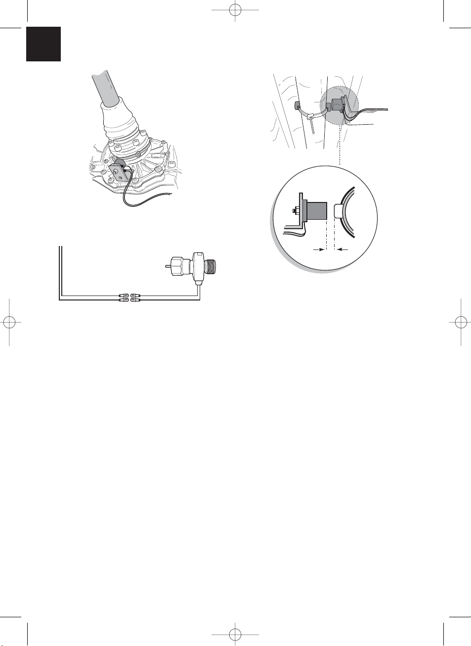
Tachowellengenerator MS-AA-144 (siehe ✎ I 3)
Der Tachowellengenerator dient zur Erzeugung eines Geschwindigkeitssignals bei Fahrzeugen mit geschraubter Tachowelle. Bei Verwendung des Tachwollengenerators bei
Fahrzeugen mit manuellen Schaltgetrieben ist es zwingend notwendig, einen Motorüberdrehungsschutz zu installieren.
MS-400.qxd 24/06/03 15:10 Page 38
Page 39

39
MS-400.qxd 24/06/03 15:10 Page 39
Bremspedal treten und niedergetreten halten
•
Bremspedal treten und niedergetreten halten
•
BETRIEB
STANDARD-
• Motor starten
• Viermal auf die SET-Taste drücken
• Bremspedal treten und niedergetreten halten
• Taste ON/OFF auf dem Bedienmodul drücken
Einstellmodus
Bremspedal treten und niedergetreten halten
•
Piepstöne)
(4 hochtönende
GAIN manuell
Bremspedal wieder loslassen
•
Viermal auf die RES-Taste drücken
•
Bremspedal wieder loslassen
•
Dreimal auf die RES-Taste drücken
•
Bremspedal wieder loslassen
•
Zweimal auf die RES-Taste drücken
•
Den Wagen mit einer beliebigen
komfortablen Geschwindigkeit fahren
Piepstöne)
(3 hochtönende
INIT manuell
Den Wagen mit einer beliebigen
komfortablen Geschwindigkeit fahren
Piepstöne)
(2 hochtönende
PPM manuell
Den Wagen mit Einschalt-
geschwindigkeit (35 - 40 km/h) fahren
drücken
SET-Taste
drücken
SET-Taste
Signalart
GAIN-Wert
Beschleunigen Abbremsen
INIT-Wert
Beschleunigen Abbremsen
signal
drücken
RES-Taste
Umdrehungs-
drücken
keitssignal
SET-Taste
Geschwindig-
drücken
RES-Taste
Ja
drücken
SET-Taste
RES-Taste
SET-Taste
Bremse?
1 Piepston/Zählwert
Nein
drücken
Ja
drücken
Bremse?
1 Piepston/Zählwert
Nein
Betriebsart PPM verlassen und
die PPM-Einstellung speichern
die PPM-Einstellung speichern
Betriebsart PPM verlassen und
die PPM-Einstellung speichern
Betriebsart PPM verlassen und
signal
Piepston)
(1 hochtönender
Auto Setup
PPM-INT-GAIN
Bremspedal wieder loslassen
•
Einmal auf die RES-Taste drücken
•
Bremspedal treten und niedergetreten halten
•
Signalart
Den Wagen mit einer
Geschwindigkeit von 70 km/h fahren
drücken
RES-Taste
Umdrehungs-
drücken
keitssignal
SET-Taste
Geschwindig-
INIT-Wert
drücken
RES-Taste
drücken
SET-Taste
Beschleunigen Abbremsen
1 Piepston/Zählwert
Ja
Bremse?
und die Einstellung speichern
Betriebsart Auto Setup verlassen
Nein
Setup-Modus verlassen: Bremspedal treten und niedergetreten halten; viermal auf die SET-Taste drücken (ein langanhaltender hoher Piepston ertönt)
Page 40

40
Entsorgungshinweis
Beachten Sie bitte, dass elektrische Geräte eine Vielzahl wieder verwertbarer Materialien sowie umweltschädliche Komponenten enthalten. Tragen Sie bitte in Ihrem
und im Interesse der Umwelt.
Sorge dafür, dass diese Komponenten nur über die vorgesehenen und zugelassenen
Wege entsorgt werden.
Betriebsspannung: 12 Volt
Stromaufnahme: max. 3 A
Betriebstemperatur: -40° bis +85° C
ABE Nr. 90668
Technische Änderungen Vorbehalten
Technische Daten
MS-400.qxd 24/06/03 15:10 Page 40
Page 41

41
List of contents
Read these operating instructions before installing the attachment.
Illustrations for the installation instruction . . . . . . . . . . . . . . . . . . . . . . . . . . . . . . . . . .3-12
List of contents . . . . . . . . . . . . . . . . . . . . . . . . . . . . . . . . . . . . . . . . . . . . . . . . . . . . . .41
Information for using the installation instructions . . . . . . . . . . . . . . . . . . . . . . . . . . . . . .41
General safety and installation instructions . . . . . . . . . . . . . . . . . . . . . . . . . . . . . . . . . .42
Scope of delivery . . . . . . . . . . . . . . . . . . . . . . . . . . . . . . . . . . . . . . . . . . . . . . . . . . . . .44
Required tools . . . . . . . . . . . . . . . . . . . . . . . . . . . . . . . . . . . . . . . . . . . . . . . . . . . . . . . .45
Command module . . . . . . . . . . . . . . . . . . . . . . . . . . . . . . . . . . . . . . . . . . . . . . . . . . . .45
Actuator . . . . . . . . . . . . . . . . . . . . . . . . . . . . . . . . . . . . . . . . . . . . . . . . . . . . . . . . . . . .45
Vacuum connection . . . . . . . . . . . . . . . . . . . . . . . . . . . . . . . . . . . . . . . . . . . . . . . . . . . .46
Fitting the throttle lever . . . . . . . . . . . . . . . . . . . . . . . . . . . . . . . . . . . . . . . . . . . . . . . . .46
Electronics module . . . . . . . . . . . . . . . . . . . . . . . . . . . . . . . . . . . . . . . . . . . . . . . . . . . .47
Cable harness . . . . . . . . . . . . . . . . . . . . . . . . . . . . . . . . . . . . . . . . . . . . . . . . . . . . . . . .47
Diagnostic mode . . . . . . . . . . . . . . . . . . . . . . . . . . . . . . . . . . . . . . . . . . . . . . . . . . . . . .53
Safety devices . . . . . . . . . . . . . . . . . . . . . . . . . . . . . . . . . . . . . . . . . . . . . . . . . . . . . . .55
Adjustment/training mode . . . . . . . . . . . . . . . . . . . . . . . . . . . . . . . . . . . . . . . . . . . . . . .56
Operation of the cruise control . . . . . . . . . . . . . . . . . . . . . . . . . . . . . . . . . . . . . . . . . . .61
Function test . . . . . . . . . . . . . . . . . . . . . . . . . . . . . . . . . . . . . . . . . . . . . . . . . . . . . . . .62
Troubleshooting . . . . . . . . . . . . . . . . . . . . . . . . . . . . . . . . . . . . . . . . . . . . . . . . . . . . . .63
Accessories . . . . . . . . . . . . . . . . . . . . . . . . . . . . . . . . . . . . . . . . . . . . . . . . . . . . . . . . .65
Adjustment mode . . . . . . . . . . . . . . . . . . . . . . . . . . . . . . . . . . . . . . . . . . . . . . . . . . . . .67
Disposal instructions . . . . . . . . . . . . . . . . . . . . . . . . . . . . . . . . . . . . . . . . . . . . . . . . . . .68
Technical data . . . . . . . . . . . . . . . . . . . . . . . . . . . . . . . . . . . . . . . . . . . . . . . . . . . . . . . .68
Information for using the installation instructions
Warning! Safety instruction:
Failure in observing these warnings may result in injuries to persons or damage
to material.
Attention! Safety precaution:
Failure in observing these warnings may result in damage to material and
improper functioning of the cruise control MS-400.
The rhombus marks installation steps which you have to implement.
Read through these installation and operating instructions before beginning the assembly,
so that the installation can be made without any difficulties. If the operating instructions
do not answer all your questions, or if the assembly steps are not clear, please do not
hesitate to contact our customer technical support service.
Waeco UK Ltd.
UK-Broadmayne · Dorset DT2 8LY · Unit G1 · Roman Hill Business Park
phone: +44-13 05/85 40 00
fax: +44-13 05/85 42 88
Internet: http://www.waeco.com
◆
MS-400.qxd 24/06/03 15:10 Page 41
Page 42

42
Safety and installation instructions
Warning!Inadequate cable connections can lead to short-circuits which cause
the following:
• cable fires
• triggering of the airbag
• damage to electronic control equipment
• failure of electrical functions (blinkers, brake-lights, horn, ignition, lights).
Please note the following:
When working on the cabling of the vehicle, the following terminal designations
apply:
30 (input of battery plus direct),
15 (switched plus, behind battery)
31 (recirculation from battery, mass)
58 (parking light) (back-up light)
The securest form of connection is obtained by solderingthe cable ends and then
insulating the connection.
For detachable connections, only insulated cable lugs, connector plugs, and flat pin
bushings must be used. Do not use insulating screw joints.
Use crimping pliers to connecting the cables with cable lugs, plugs or flat pin bushings.
With cable connections to 31 (mass):
Screw the cable with cable lug and toothed lock washer to a vehicle-specific mass bolt or
screw it with a cable lug, self-tapping screw and toothed lock washer to the car’s
bodywork.
Always ensure that the connection is properly earthed!
Warning! Due to the risk of short-circuits, always disconnect the negative
terminal of the battery before starting to work on the electrical equipment of the
vehicle. If the vehicle is equipped with a supplementary battery, also disconnect
its negative terminal.
Caution!When disconnecting the negative terminal of the battery, all volatile
memories of the comfort-electronics lose their stored data.
MS-400.qxd 24/06/03 15:10 Page 42
Page 43

43
MS-400.qxd 24/06/03 15:10 Page 43
Safety and installation instructions
Depending on the vehicle’s equipment, the following date may need to be reprogrammed:
Radio-code…vehicle clock timeswitch clock onboard computer seat position
Instructions on how to reset these can be found in the relevant operating instructions.
Caution! Only a voltmeter may be used to check the voltage in electrical cables
(see ✎ B 2).
Caution! To avoid damage, always ensure that there is enough space for the
drill bit to emerge. Every drill hole must be deburred and treated with a
rustproofing agent.
Caution! When installing the electrical connections, ensure they:
are not sharply bent and twisted,
2. do not rub at the edges,
3. are not inserted through sharp-edged openings.
Caution! Ensure that it is not necessary for the driver to insert his hand through
the steering wheel and that the MagicSpeed components are not within the
deployment area of the vehicle’s airbag and the head impact range.
WAECO International does not accept any liability for damages due to the following:
a) incorrect assembly
b) damage to the system by mechanical effects and overvoltages
c) modifications to MagicSpeed without the explicit approval of WAECO International
d) use for any purposes other than those described in the assembly instructions.
Page 44

44
Scope of delivery
Article Parts No. Piece Description
(see ✎ A 1) AS86040 1 Electronics module
(see ✎ A 2) AS86020 1 Actuator
(see ✎ A 3) PR9755A 1 Vacuum hose
(see ✎ A 4) WH58030 1 Cable harness
AS86030 1 Assembly kit
(see ✎ A 5.1) 1 Throttle lever
(see ✎ A 5.2) 3 Splice protection
(see ✎ A 5.3) 1 Throttle lever clamp
(see ✎ A 5.4) 1 Tooth locked washer M8
(see ✎ A 5.5) 1 Rotating bolt
(see ✎ A 5.6) 1 Self-locking nut M4
(see ✎ A 5.7) 1 Washer M4
(see ✎ A 5.8) 2 Nylon washer M5
(see ✎ A 5.9) 1 Split pin
(see ✎ A 5.10) 1 Mounting plate
(see ✎ A 5.11) 1 Mounting angle for throttle lever
(see ✎ A 5.12) 1 Toothed locked washer M6
(see ✎ A 5.13) 1 Nut M6
(see ✎ A 5.14) 1 Machine bolt M6x12
(see ✎ A 5.15) 1 T-piece 5 mm
(see ✎ A 5.16) 1 T-piece 1/4” to 5/16”
(see ✎ A 5.17) 1 T-piece 3/8” to 1/2”
(see ✎ A 5.18) 3 Machine bolt M6x15
(see ✎ A 5.19) 1 Machine bolt M6x12
(see ✎ A 5.20) 2 Thread screw, black
(see ✎ A 5.21) 3 Nut M6
(see ✎ A 5.22) 3 Spring washer M6
(see ✎ A 5.23) 2 Flat disc M6
(see ✎ A 5.24) 1 Special toothed lock washer M6
(see ✎ A 5.25) 1 Cable clamp
(see ✎ A 5.26) 1 Allen screw M4x6
(see ✎ A 5.27) 1 End clamp
(see ✎ A 5.28) 1 Allen screw M4x4
(see ✎ A 5.29) 1 Allen screw M2
(see ✎ A 5.30) 1 Rubber bushing
(see ✎ A 5.31) 10 Cable tie
(see ✎ A 5.32) 1 Double-sided adhesive tape
(see ✎ A 5.33) 2 Bolt 8x1/2
(see ✎ A 6) AS 40420 1 Clutch switch
MS-400.qxd 24/06/03 15:10 Page 44
Page 45

45
Actuator
The actuator should be mounted in the engine compartment at the splash plate or on the
inner mudguards (see ✎ D 1). It is important to ensure that the actuator is not mounted in
the vicinity of a heat source and at a distance of at least 300 m from any high-voltage
source such as an ignition distributor, ignition coil, ignition cable or generator. The throttle
lever of the actuator should be led in a bow of at least 300 mm to the original accelerator
cable or throttle control lever.
Caution! Keep the throttle lever away from rotating or hot surfaces or parts.
It is possible to fasten the mounting plate of the actuator at 4 different positions at the
actuator, whereby a maximum flexibility will be ensured with the assembly (see ✎ D 2).
Command module
Module, (see ✎ C)
Required tools
The tools required for the correct assembly of the cruise control are listed below: Although this equipment can be mounted without some of the listed tools, we recommend
having these tools handy. It is highly recommended that you solder the connections to
ensure a stable connection.
- drill (see ✎ B 1) - car jack (see ✎ B 11)
- voltmeter (see ✎ B 2) - set of screwdrivers (see ✎ B 12)
- soldering iron and material (see B 3) - set of socket wrenches (see ✎ B 13)
- wire-cutting pliers (see ✎ B 4) - axle assembly bay (see ✎ B 14)
- insulation stripping tongs (see ✎ B 5) - insulating tape (see ✎ B 15)
- crimping pliers (see ✎ B 6) - ruler (see ✎ B 16)
- pliers (see ✎ B 7) - screw wrench (see ✎ B 17)
- drill set (see ✎ B 8) - set of ring spanner wrenches (see ✎ B 18)
- prick punch (see ✎ B 9) - sealing compound (see B 19)
- hammer (see ✎ B 10)
MS-400.qxd 24/06/03 15:10 Page 45
Page 46

46
Vacuum connection
Select a good, unrestricted vacuum source in order to connect the vacuum hose to the
actuator. The most common source is located directly at the air intake manifold (see ✎ E
1) or between the intake manifold and the brake power assist unit (see ✎ E 2). Do not use
any vacuum control lines,
e.g. the vacuum line of the ignition distributor or the AGR (exhaust gas recirculation valve)
vacuum controller. In vehiclesequipped with a separate vacuum pump, a connection between the pump and the backpressure valve of the vacuum brake power assist unit is recommended.
Fitting the throttle lever
Caution! Although your cruise control is equipped with different safety features,
these are not, however, able to prevent a distortion or locking of the original
cable or throttle linkage. Check the original cable or the original throttle linkage
manually and by depressing the accelerator pedal in order to ensure that the
throttle linkage or the cable are functioning correctly and do not lock during
activation.
Possibility 1
Fitting to the existing accelerator or an additionally mounted accelerator. The MS-400
throttle lever will be fitted with the rotating bolt. The throttle lever of the MS-400 can slip
through the bolt when the accelerator is pressed (see ✎ F 1, F 3, F 4).
Possibility 2
Fitting directly to the throttle lever.
The throttle lever of theMS-400 will be fitted to the cable wire clamp to the throttle cable
(see ✎ F 5, F 6, F 7). The throttle lever of the MS -400 can slip through the bolt when the
accelerator is pressed.
Possibility 3
Some newer vehicles no longer possess a carburettor control cable. In these vehicles, a
direct connection with the accelerator pedal is required. However, the most suitable
location to fit the actuator is in the engine compartment, since otherwise the working
valves in the actuator can cause nuisance noise. The throttle lever of the MS-400 should
be led through the splashplate into the passenger cabin (see ✎ F 8).
MS-400.qxd 24/06/03 15:10 Page 46
Page 47

47
Electronics module
The electronics module should always be mounted with 4 mm metal bolts or the supplied
double-sided adhesive tape in the passenger cabin of the vehicle. Avoid locations with
exposure to significant heat, humidity and high-voltage components. Preferred assembly
locations: Under the dashboard on the driver’s side, behind the glove compartment or the
footboard of the driver’s side or passenger side (see ✎ G). Do not mount the electronics
module inside the engine compartment. Mark the drill holes, prick punch and drill two 3mm-drill holes for the assembly. Always check the discharge side for free passage before
drilling.
Te mporarily install the electronics module in the selected position.
The cable passage must be determined first before securing the electronics module.
When assembly is complete, attach the module in the selected position.
Cable harness
Once the installation location of the electronics module has been determined, the cable
harness of the cruise control can be fitted.
Command module (see ✎ H 1). A number of command modules are available in each
application to ensuere a degree of operating comfort. The cruise control’s command
module must be fitted in a location where safe working can be guaranteed under any
circumstances. Suitable locations are on the dashboard or the central console, depending
on the design and accessibility as well as the command module.
After selecting a suitable location for the command module, a 6 mm large drill hole must
be drilled in the vicinity of the command module. The cables of the commandmodule can
now be led through this drill hole to the cable harness of the cruise control. The cable
connections of the command module can now be pushed into the compact connector
and inserted into the 8-pin empty housing. Connect the assembled 8-pin compact
connector from the control unit to the 8-pin connector of the main cable harness.
MS-400.qxd 24/06/03 15:10 Page 47
Page 48

48
Cable harness
Infrared command module and control column – command module:
Both the infrared and the control column – command module are supplied with their own
assembly instructions. These instructions must be read carefully prior to performing the
assembly.
Caution! Ensure that the driver is not required to insert his hand through the
steering wheel to operate the module.
Green/red, black, pink/red and blue/red
Lead the 4-lead cable for the actuator through a suitable passage or through a specially
prepared passage that is sealed with the supplied rubbergasket into the engine
compartment. Insert the 4 cables into the empty housing of the connector and connect
to the actuator. Pay attention to the colourcoding on the empty housing of the connector.
Orange cable
Connect the orange cable to a switched positive terminal (terminal 15) Ensure that the
switched positive terminal is receiving the full operating voltage (12 V) and that the cable
is idle when the ignition is switched off.
Reference! The feed selected via the ignition should be checked with a
voltmeter on its full battery voltage. The fuse box is usually a suitable location.
Connecting the orange cable to the voltage supply of the vehicle accessories
(ACC) is not recommended.
Green cable
Connect the green cable to an existing vehicle earth or to the bare metal earthing
connection of the car body. The most common location for a central vehicle earth is the
left or right A-pillar.
Brown and brown-white cable
Connect the brown and brown-white cable with the brake light switch (see H 2).
MS-400.qxd 24/06/03 15:10 Page 48
Page 49

49
Cable harness
If more than two cables run from the brake light switch, then a voltmeter must be used to
identify the necessary cable. One of the two original cables in the brake light switch
should have a continuous positive terminal (terminal 30, 12 V) or a switched positive
terminal (terminal 15). A voltage of +12 V should be adjacent to the brake in operation
with the second original cable. As soon as the brake is released, the cable must conduct
no voltage.
If you are unable to measure any full + 12 V at the brake light switch, then it is possible
that the vehicle is equipped with a computer-controlled braking system. In this case, you
must connect the brown cables as follows: Connect the brown-white cable to a
protected, switched positive terminal (terminal 15). Connect the brown cable to the
original wire which leads to the brake lights. This cable carries + 12 V when the brake is
in operation and 0 V when the brake is released. A possible location where these cables
may be found is directly inside the rear-lights or in the wiring loom to the rear of the
vehicle.
Yellow and blue signal cable
(Connection of the speed- or rotational speed signal). There are two different ways to pick
up a reference signal for the cruise control:
1. Speed signal
The speed signal serves as the real indication of the travel speed. This signal type should
be always used in automatic transmission vehicles, but is also suitable for manual
transmission vehicles, whereby in this case a cut-off must be installed to prevents the
engine over-revving (see page 51).
2. Engine speed (RPM)
The engine speed signal serves to indicate the engine speed (RPM). The vehicle speed
therefore depends on the engine speed as long as the vehicle is travelling in the same
gear. The engine speed signal is only suitable for manual transmission vehicles. In this
case, a cut-off must be installed again to prevent the engine from overrevving
(see page 52).
MS-400.qxd 24/06/03 15:10 Page 49
Page 50

50
Cable harness
The cruise control is equipped with two cables, which can be used for the identification of
signals.
1. Blue cable
This serves to identify the cruise signal and the speed signal with a voltage between 1.5
volts and 24 volts and a frequency between 6 Hz and 8.5 kHz. The blue cable should be
used for all signals which apply to the range between the two above mentioned
parameters, i.e. both for the cruise signal and for the engine speed.
2. Yellow cable
It serves only to identify the speed signal with a voltage between 6 volts and 250 volts
and a frequency between 6 Hz and 488 kHz. The yellow cable should be used only to
identify speed signals with a voltage of > 20 volts. Otherwise the yellow cable should be
used only in those cases or applications where engineover-speed protection is also
necessary or the speed signal varies within a range of 6 to 250 volts.
Engine overspeed protection
If a cruise signal is used as signal source in vehicles with manual transmission, then an
engine overspeed protection must be also available so as to prevent engine damage. If
the clutch is depressed whilst the cruise control is activated, then the cruise control must
switch itself off automatically, otherwise damage to the vehicle’s engine can occur.
There are two types of engine overspeed protection:
1. If the blue cable is used to transfer the cruise signal, then the yellow cable can be
connected to transfer the engine speed so as to ensure the necessary engine
protection. See also the paragraph on determining the cruise command signals.
2. If an appropriate speed signal does not exist, it is also possible to use a clutch switch.
The clutch switch should be fitted on the clutch pedal so that the cruise control
switches itself off automatically when the clutch pedal is activated (see H 4).
MS-400.qxd 24/06/03 15:10 Page 50
Page 51

51
Cable harness
The signal pick-up is always depends on the type of transmission used by the vehicle.
Vehicles with automatic transmission
The blue cable should be used, which must be connected herewith for the transfer of the
cruise signal. In no event may a speed signal be used. No additional overspeed
protection is necessary for vehicles with automatic transmission. See also the paragraph
on determining the appropriate cruise signals. If an appropriate cruise signal cannot be
detected at the vehicle, then the optional magnet sensor kit or the optional cruise pulse
generator may be fitted (see optional accessories on page 65).
Vehicles with manual transmission
The best solution at vehicles with manual transmissions is the allocation of the blue cable
to the cruise signal and the use of the yellow cable as overspeed protection by means of
speed signal or clutch switch. See also the paragraph on determining the appropriate
cruise impulse signals. If an appropriate cruise signal cannot be detected, then the
optional magnet sensor kit or the optional cruise pulse generator can be fitted. If a cruise
signal cannot detected in the vehicle, then the blue cable may be allocated with the
speed signal or the yellow cable can be connected to the negative terminal of the ignition
coil (terminal 1). With this solution additional overspeed protection is no longer required,
since the engine speed is monitored herewith by the cruise control. When using a speed
signal the minimum speed for activation of the cruise control depends on the gear the
vehicle is at that moment.
Pick-up of the cruise or speed signal
There are different ways to pick up the speed or cruise signal for cruise control. In the
following section, there are different ways of identifying the signal.
MS-400.qxd 24/06/03 15:10 Page 51
Page 52

52
Cable harness
Cruise signals
It is absolutely imperative to install engine overspeed protection on vehicles with manual
transmission.
a. Cruise signal that is transferred via the engine control.
Voltage: between 1.5 and 24 volts, frequency: between 6 Hz and 8.5 kHz.
b. Electronic speedometer – on the rear of the instrument unit or as partial kit of the
instrument unit.
Voltage: between 1.5 and 24 volts, frequency: between 6 Hz and 8,5 kHz.
c. Cruise sensor – installed in the gearbox and generally having 3 cables.
Voltage: between 1.5 and 24 volts, frequency: between 6 Hz and 8,5 kHz.
d. Car radio – next to the radio if the vehicle is equipped with an ISO connection.
The cruise pulse is here in chamber 3, wiring pin 1 or 5.
Voltage: between 1.5 and 24 volts, frequency: between 6 Hz and 8.5 kHz.
Engine speed signals
a. Engine speed signal transferred via the engine control.
1.5-24 volts.
b. Electronic speedometer – on the rear of the instrument unit.
Voltage: between 1.5 and 24 volts, frequency: between 6 Hz and 488 Hz.
c. Terminal at the W+ pole of the generator, some generators are equipped with an
additional terminal. This terminal is not allocated on some vehicles, meaning a
connection to the generator is required. Voltage: 6-250 volts; frequency: between 6 Hz
and 488 Hz.
d. Negative terminal side of the ignition coil (terminal 1) – the yellow cable must be used
with this type of connection.
Voltage: 6-250 volts; frequency: between 6 Hz and 488 kHz.
Use a voltmeter to check the selected signal and proceed as follows: Connect the red
wire of the voltmeter to the cruise signal selected by you and the black wire of the
voltmeter to the vehicle earth. Now start driving the vehicle at the lowest speed at which
cruise control can be activated, and measure the the effectivevoltage of the signal. Ensure
that all digital voltmeters measure the effective voltage if they are in the alternating
voltage area.
MS-400.qxd 24/06/03 15:10 Page 52
Page 53

53
Diagnostic mode
Cruise control has a self-diagnostic mode. The self-diagnostic mode is divided into three
areas A, B and C, to test all elements and functions of cruise control. Before starting
self-diagnostic mode, recheck all cable connections for the correct connection.
Move the manual gearshift into neutral or the automatic gearshift into park, then apply
the hand brake.
Switch the ignition ON with the SET-button depressed to start the diagnostic function
with an acoustic display. An acoustic acknowledgment signal will be displayed as long as
you keep the SET button depressed and the ignition is switched on. If you hear an
additional acoustic signal within one second of releasing the SET button, a control input
is switched on, e.g. the clutch switch. Check the cable connections again.
Diagnostic mode A
Testing the electronic components and electrical connections
The LED in the electronics module and the integrated buzzer indicate, in parallel, the
correct functions of the electrical wiring and components.
It is not absolutely necessary, in a later inspection of the components, to uncover the
control unit, since the acoustic signals are parallel to the visual signals.
A confirmation via the LED or buzzer will be received if the following signals are activated
or pending:
SET-button
RES-button
Brake
Clutch switch
Cruise signal in training mode
Speed signal in training mode
The acoustic and visual signal is displayed for a maximum of 10 seconds per inputto
ensure that further messages are not prevented. If you do not obtain an acoustic or visual
signal when activating one of the above mentioned functions, you must check the
electrical wiring.
MS-400.qxd 24/06/03 15:10 Page 53
Page 54

54
Diagnostic mode
Diagnostic mode B
When test A has been successfully completed, proceed to test B. You can check the
function of the actuator with this diagnostic mode. Move the manual gearshift into neutral
or the automatic gearshift into park, then apply the hand brake Start the engine with the
SET button depressed. Release the SET button when the engine is running. Then switch
on cruise control with the ON/OFF button. The LED in the control unit lights up. Press the
SET-button and keep it pressed down. The engine speed must slowly rise (warning: do
not allow the engine to overspeed). Press the RES button and keep it pressed down. The
engine speed should slowly decrease. The engine speed should decrease again to a
neutral speed position by applying the brake or clutch or activating the ON/OFF switch.
Switch off the ignition when leaving the diagnostic mode.
Diagnostic mode C
The diagnostic mode C is used to check the cruise signal or speed signal. Start the
engine with the SET button depressed. Release the SET button when the engine is
running. Drive the vehicle at a speed of approx. 50 km/h. Switch on cruise control with
the On/Off-button in the control unit. The LED in the control unit should now flash approx.
once per second and you should receive an acoustic signal approx. once per second.
Activate the adjustment- and training program if it is not already activated. When the
vehicle stops, switch off the ignition to leave diagnostic mode.
Note! The diagnostic modes are used to check all components and functions of
cruise control. Cruise control uses an internally created reference signal to test
the actuator in diagnostic mode B. If cruise control does not work correctly
after successful completion of test B, then the problem is usually the pickup of
the cruise signal.
MS-400.qxd 24/06/03 15:10 Page 54
Page 55

55
Safety devices
Cruise control is equipped with numerous safety devices. These safety devices deactivate
cruise control if one or several of the following specified situations should occur:
1. When depressing the brake pedal;
2. when pressing the OFF-button on the control module;
3. when an engine overspeed condition occurs;
4. when decelerating to 50% of the adjusted speed;
5. when accelerating to 150% of the adjusted speed;
6. when switching off the ignition.
Cruise control also switches off if there are faults in the area of the brake light such as
e.g. defective brake lights, a defective fuse or a loose connection in the area of the brake
light switch.
To ensure safe and efficient operation, NEVER use cruise control in traffic jams or on wet,
slippery roads.
Attention! Cruise control also switches off if there are faults in the area of the
brake light such as e.g. defective brake lights, a defective fuse or a loose
connection in the area of the brake light switch.
Caution! Cruise control is equipped with a number of safety devices. However,
none of them is able to prevent twisting and jamming of the throttle lever.
Therefore, check everything twice!
MS-400.qxd 24/06/03 15:10 Page 55
Page 56

56
Adjusting-/training mode
The most important cruise control parameters can be adjusted almost optimally for each
vehicle with the adjustment- and training mode.
The cruise or speed signal (PPM), the sensitivity of the takeover (INIT-mode) and the control sensitivity (GAIN-mode) are adjusted by the three adjustment and training modes.
The basic parameter may be adjusted while driving. Thus you are able to adjust the fine
adjustment of the control parameters individuallyand thus obtain an exact adjustment.
These adjustments can be performed without removing the control unit to enable access
to the switches for special adjustments.
The adjustments or calibrations are performed electronically. The adjusted parameters are
securely saved in the electronics module until the SETUP program is restarted.
1. Starting SETUP mode
Proceed as follows when starting the SETUP program:
Switch the ignition ON and off, start the vehicle, depress the brake and keep the brake
depressed for one minute. While depressing the brake, press the SET button four times
briefly in succession. You will hear 4 high-pitched acoustic signals as confirmation.
Always start the above-specified procedure to start one of the adjustment and training
modes as mentioned below.
2. Automatic mode
In automatic mode, all three parameters (PPM, GAI and INIT) are synchronized
automatically to your vehicle. Following automatic mode, you are still able to adjust all
three parameters.
To go into automatic mode, after performing the steps specified under point 1, depress
the brake and press the RES button with brake activated. You will hear a low acoustic
signal as confirmation. Release the brake. You will hear a high acoustic signal as
confirmation. Repeat the process if you hear more than one acoustic signal.
Drive your vehicle at a speed of 70 km/h.
Press the SET button for the blue wire as signal input or press the RES button for the
yellow wire as a signal input.
MS-400.qxd 24/06/03 15:10 Page 56
Page 57

57
Adjustment/training mode
Cruise control switches itself on immediately after pressing the SET- or RESbutton and
enters INIT mode. It is possible to optimize the response behaviour in this mode and thus
adjust the neutral gear of the throttle lever of the actuator. If cruise control has taken over
the speed too slowly, press the SET button to increase the value.
If cruise control has taken over the speed too jerkily, causing oversteer, then the RES
button must be pressed. You obtain an acoustic signal as confirmation for each keystroke
on the SET or RES button.
Depress the brake to save the adjusted values (PPM, INIT and GAIN).
Now you can call up the program once again by pressing the RES button while the brake
is activated. You will hear a low acoustic signal as confirmation. Release the brake. You
will hear a low acoustic signal as confirmation after releasing the brake. Restart the
program from the beginning by pressing the SET or RES button depending on the signal
source. Stop your vehicle to leave the SETUP program and press the SET button 4 times
while the brake is activated.
Normally, cruise control should be adjusted optimally for your vehicle.
3. PPM adjustment
If you are not satisfied with the range of control of the cruise control, then you can adjust
the PPM setting manually.
First start the SETUP-program to reach PPM setting mode.
Now press the RES button twice while the brake is activated. You will hear a low acoustic
signal as a confirmation of each keystroke. Release the brake. You will hear two high
acoustic signals
asa confirmation after releasing the brake. If you do not hear two high acoustic signals,
the above-mentioned steps must be performed again.
Drive the vehicle at a speed of 35-40 km/h to adjust the PPM value. Now press the SET
button for the blue cable as the signal input, or the RES button for the yellow cable as the
signal input. Cruise control switches itself on immediately after you press the SET or RES
button and it switches to normal mode. Depress the brake to save the adjusted values
(PPM).
MS-400.qxd 24/06/03 15:10 Page 57
Page 58

58
Adjustment/training mode
Stop the vehicle to leave the SETUP program and press the SET button 4 times while the
brake is activated.
After each modification of the PPM setting, all previous INIT-settings are overwritten with
the factory default settings; however, the GAIN setting remains unmodified.
If cruise control now take over the speed too slowly or too jerkily, the INIT setting must be
performed. If cruise control works too slowly or jerkily in normal operation, the GAIN setting must be performed manually.
If cruise control works too slowly or too jerkily in normal operation, the GAIN setting
must be performed manually.
4. INIT mode
You can adjust the sensitivity of the speed takeover inINIT mode.
If cruise control takes over the speed too slowly, the INIT value must be increased. If the
speed is taken over too jerkily, the INIT value must be decreased.
First start the SETUP-program to reach the INIT setting mode.
Now press the RES button three times while the brake is activated. You will hear a low
acoustic
signal as a confirmation of each keystroke. Release the brake. You will hear three high
acoustic signals as a confirmation after releasing the brake. If you do not hear three high
acoustic signals, the above-mentioned steps must be performed again.
Drive at cruise control at any speed you like above the minimum speed (40 km/h). Now
press the SET button
until you notice cruise control taking over the speed at which you are driving. Switch off
cruise control by activating the brake. Press the SET button again; cruise control should
now take over the speed gently. If this is not the case, you can increase the INIT value
using the SET button and decrease the value using the RES button. You will hear an
acoustic signal for each keystroke.
MS-400.qxd 24/06/03 15:10 Page 58
Page 59

59
Adjustment/training mode
Attention! The normal UP and DOWN functions of the SET button and RES
button are locked in this mode of operation so that these buttons can be used
to input the settings.
Depress the brake to save the adjusted values (PPM, INIT and GAIN). If the INIT value is
modified, then cruise control calculates the best possible GAIN value and clears the
previous value in the control unit.
Normally, no further setting must be performed in the control unit. Therefore, it is
recommended that you leave SETUP mode and test out cruise control in normal
operation. Stop your vehicle to leave the SETUP program and press the SET button 4
times while the brake is activated.
If the cruise control reacts too slowly or too sensitively during normal operation, the GAIN
value must be modified. Repeat step 1 and 5 again to start GAIN mode.
5. GAIN mode
The GAIN value must be increased if the vehicle decelerates or reacts too slowly with the
operation of cruise control, e.g. excessive speed loss going up hills or excessive speed
increase going down hills.
The GAIN value must be decreased if the vehicle accelerates with the operation of cruise
control or if it moves too jerkily. For example: You set a speed of 70 km/h and the vehicle
speed changes between 65 and 75 km/h during normal operation. Normally, the GAIN
value, which is calculated after effected INIT setting has been done, ensures the constant
normal operation of cruise control. If a modification is necessary, the following procedure
should be followed:
First start the SETUP-program to reach GAIN setting mode.
Now press the RES button four times while the brake is activated. You will hear a low
acoustic signal as a confirmation of each keystroke. Release the brake. You will hear four
high acoustic signals asa confirmation after releasing the brake. If you do not hear four
high acoustic signals, the above-mentioned steps must be performed again.
MS-400.qxd 24/06/03 15:10 Page 59
Page 60

60
Adjustment/training mode
Drive the vehicle at a moderate speed to adjust the GAIN value. Press the SET button to
activate cruise control. Press the SET button again to increase the GAIN value or press
the RES button to decrease the GAIN value. You will hear an acoustic signal as a
confirmation of each keystroke.
Below you will find a practical procedure for adjusting the GAIN value optimally after you
have set cruise control into the setting mode (see above).
When driving your vehicle at a moderate speed, press the SET button to activate cruise
control. Switch off normal operation by activating the brake. Let the vehicle’s speed
decrease by approx. 25-30 km/h. Press the RES key to recall the last saved speed. Now
look at the vehicle’s speedometer. If the speed increases beyond the last saved speed,
then the GAIN value must be decreased by pressing the SET button again. If the cruise
control has taken up the speed too slowly, press the SET button to increase the GAIN
value.
Depress the brake to save the adjusted value. Press the RES button to check the setting.
If the setting is not satisfactory, you can modify the GAIN value as described above.
Depress the brake after successful setting to save the value. Point 6 must be observed
when leaving SETUP mode.
6. Leaving the SETUP mode
Stop your vehicle to leave the SETUP program and press the RES button 4 times while
the brake is activated.
You will hear a long, high acoustic signal as a confirmation that the SETUP program is
finished.
MS-400.qxd 24/06/03 15:10 Page 60
Page 61

61
Operation of cruise control
ON/OFF-button
Cruise control is switched on by pressing the ON/OFF button once. The LED lights up as
confirmation.
If cruise control is switched on, it is switched off by pressing the ON/OFF switch once.
The LED goes out as confirmation.
SET button
1. Setting of the currently driven speed if the SET button is pressed and released again
immediately. This desired speed is then maintained until:
a) the brake- or the clutch pedal is depressed
b) the unit is switched off via the ON/OFF button
c) the speed of the vehicle is below the lower switch-on speed
d) the speed decelerates by more than approx. 25% when going down a hill
2. If the “SET“ button is pressed and held down, the vehicle will accelerate. When the
button is released, cruise control will store the speed that has been attained and will
maintain that speed.
RES button
If the “RES” button is pressed and immediately released, the last speed that was stored
is re-entered, provided that:
a) the unit is switched on via the ON/OFF button;
b) the speed of your vehicle is not below the minimum speed;
c) the brake or clutch pedal is not depressed;
d) the ignition has not been switched off in the meantime;
e) the current speed is not less than 50% of the stored value.
Accelerating and decelerating
When cruise control is activated, you can also make fine adjustments. If you press the
“SET” button once, the speed increases by approx. 1.5 km/h. If you press the “RES”
button once, the speed decreases by approx. 1.5 km/h. This function allows you to adjust
the speed of your vehicle to the traffic flow or to a speed limit. The cruise control has a
memory to store the number of times the buttons have been pressed. For example: If you
press the “SET” button three times or the “RES” button five times, the cruise control will
accelerate or brake the vehicle by approx. 4.5 km/h or 7.5 km/h respectively.
Note:If you want to reduce the speed of your vehicle considerably, do not use
the “RES” button. Use the “OFF” switch, the brake or the clutch instead, and
then set the new speed using the SET button.
MS-400.qxd 24/06/03 15:10 Page 61
Page 62

62
Operational test
Start your vehicle and switch on the cruise control by activating the ON/OFF button at the
operating element.
While driving at a speed of 40-50 km/h, press the SET button to activate cruise control.
Cruise control should now take over the speed gently and maintain the driven speed
constantly. The lowest speed at which cruise control operates is approx. 40 km/h.
Adjusting the sensitivity
If cruise control does not switch on gently or the vehicle accelerates or decelerates during
normal operation, then appropriate calibrations can be performed to the cruise control
sensitivity settings. If cruise control takes over the driven speed to fast or jerkily, the INIT
value must be decreased. If cruise control operates too jerkily in normal operation, the
GAIN value must be decreased. If the cruise control works too sluggishly and slowly in
normal operation, the GAIN value must be increased. All sensitivity settings can be
adjusted in the setting mode; see the flowchart on page 67.
MS-400.qxd 24/06/03 15:10 Page 62
Page 63

63
Troubleshooting
This section contains a list of possible problems, as well as a list of recommended tests
to solve these problems.
The LED of the electronic module does not light up if the buttons of the
operatingelement are pressed.
Check the 8-pin compact connector which branches off from the electronics module and
ensure that it is connected properly to the operating element. Check the colour coding on
the connection plug of the operating element and ensure that the terminals are inserted
properly into the operating element. If they are inserted properly, check the current supply
and the earthconnection of the electronics module. The orange cable should have a
battery voltage of + 12 V when the ignition is switched on, and the green cable should
have a good earthing connection.
The LED of the electronics module does not light up if the brake is activated.
Ensure that the LED of the electronics module lights up when the buttons of the operating
elements are pressed. If it does not light up, the current supply and the earthing
connection of the electronics module must be checked. The orange cable should have a
battery voltage of + 12 V when the ignition is switched on, and the green cable should
have a good earthing connection.
Check the connection to the brake light switch using a voltmeter. The brown-white cable
from the electronics module should be connected to a brake light switch cable which is
either fed constantly or via the ignition. The brown cable should be connected to the
brake light switch cable, which connects the brake light bulb to the brake light switch.
You therefore receive an earth signal from the feed cable to the brake light bulb, if the
brake pedal is not activated and a plus signal (+ 12 V) if the brake pedal is activated. The
brown-white and the brown cable are interchangeable. Some brake light circuits have
a feedcable via ignition, therefore check the cable with the ignition switched on. For
safety reasons, cruise control does not operate if there are problems in the original brake
light circuit of the vehicle. Therefore, check the brake lights to make sure they are working
correctly.
MS-400.qxd 24/06/03 15:10 Page 63
Page 64

64
Troubleshooting
The LED does not flash with input of a TACH signal
(speedometer signal via the yellow wire).
Wrong TACH signal (speedometer signal). Check the signal with a voltmeter or
oscilloscope. Ensure that the signal is between 6 V and 250 V and the frequency range is
between 5 Hz and 488 hz. After checking that the yellow wire is correctly connected, test
the signal in the cruise control electronics module once again. Connect the red wire of the
voltmeter or oscilloscope to the yellow wire in the connection plug of the electronics
module. Install the second cable of the voltmeter or the oscilloscope against the earth.
Ensure that the same signal is adjacent to the electronics module as is adjacent to the
pickup of the vehicle signal. If this is not the case, recheck the pickup and check the
yellow wire for damage.
Wrong PPM setting. If the identification of the cruise signal is selected via the blue wire,
then cruise control does not work via the TACH signal (yellow wire).
Change the PPM setting to the input signal via the yellow wire.
The LED does not flash with input of a cruise signal (speed signal via the blue wire)
Wrong cruise signal. Check the signal with a voltmeter or oscilloscope. Ensure that the
signal is between 1.5 V and 24 V and the frequency range is between 5 Hz and 8.5 hz.
After checking that the blue wire is connected correctly, test the signal at the cruise
control electronics module again. Connect the red wire of the voltmeter or oscilloscope to
the blue wire in the connection plug of the electronics module. Install the second cable of
the voltmeter or the oscilloscope against the earth. Ensure that the same signal is
adjacent to the electronics module as is adjacent to the pickup of the vehicle signal. If
this is not the case, recheck the pickup and check the blue wire fordamage.
Wrong PPM setting. If the identification of the cruise signal is selected via the yellow wire,
then cruise control does not work via the TACH signal (blue wire).
Change the PPM setting to the input signal via the blue wire.
MS-400.qxd 24/06/03 15:10 Page 64
Page 65

65
Troubleshooting
The engine speed cannot be modified in the diagnostic mode B.
Perform all other tests in the diagnostic mode again to ensure that the problem does not
arise from the electrical connections of the control unit of the cruise control. Switch off
the ignition and leave the diagnostic mode. Leave the ignition switched off for a few
seconds, then press the SET button and restart the vehicle with the SET button pressed
to reach the diagnosticmode.
Repeat test B again. Check the plug connection to the actuator, making sure that the
cables are correctly seated and the colour coding of the plug is correct.
Check the selected vacuum source. Pull off the vacuum hose from the actuator and
check the vacuum at different engine speeds. If the vacuum is not constant or decreases,
select another vacuum source.
Press the SET or RES button in the diagnostic mode B. You should be able to hear the
valves working in the vacuum actuator when you press the SET or RES button.
Cruise control does not work smoothly during normal operation.
If cruise control reacts too erratically in normal operation and the driving speed changes
during normal operation, the GAIN value must be decreased. If cruise control operates
too slowly in normal operation, the GAIN value must be increased.
Accessories
Magnet sensor kit AS71430
The magnet sensor kit is used to generate a cruise signal. There are numerous assembly
possibilities available. The magnets are attached with double-sided adhesive tape to the
cardan shaft or drive shaft. Use the supplied cable clips for the final fastening of the
magnets.
MS-400.qxd 24/06/03 15:10 Page 65
Page 66

66
Accessories
Vehicles equipped with front wheel drive (see ✎ I 1) Prevent the rear wheel from moving
away, apply the hand brake and move the gearshift to neutral. Lift the front of the vehicle
high enough that there is sufficient working space available. Support the front of the
vehicle using support brackets. Never work under a vehicle that is not adequately
secured. Fasten the sensor to the mounting and determine the installation position. This
position should be as close as possible to the gear. The suitable assembly location for the
magnets is the inner joint of the drive shaft. Fix 2 magnets to the joint with double-sided
adhesive tape and secure the fixed magnets with the cable clips after distributing these
uniformly on the joint.
Position the sensor so that there is a distance of approx. 3-5 mm arises between the
magnets and the cruise sensor. Ensure that the distance between sensor and the
magnets does not decrease or become larger than 5 mm as a result of the vertical
movement of the drive shaft.
Vehicles with rear-wheel drive (see ✎ I 2) Prevent the front wheels from moving away
and move the gearshift to neutral. Lift the rear of the vehicle high enough that there is
sufficient workingspace available. Support the front of the vehicle using support brackets.
Never work under a vehicle that is not adequately secured. Fasten the sensor to the
mounting and determine the installation position. This position should be as close as
possible to the gear. The suitable assembly location for the magnets is directly in the
gearbox. Fix 1 or 2 magnets on the cardan shaft with double-sided adhesive tape and
fasten the fixed magnets with the cable clips after you have distributed these evenly on
the joint. Position the sensor sothat there is a distance of approx. 3-5 mm between the
magnets and the cruise sensor. Ensure that the distance between sensor and magnets
does not decrease orbecomes larger than 5 mm as a result of the vertical movement of
the drive shaft.
Speedometer shaft generator MS-AA-144 (see ✎ I 3) The speedometer shaft generator
is used to generate a cruise signal in vehicles with a screwed speedometer shaft. When
using the speedometer shaft generator in vehicles with manual transmission, it is
absolutely imperative to install engine overspeed protection.
MS-400.qxd 24/06/03 15:10 Page 66
Page 67

67
MS-400.qxd 24/06/03 15:10 Page 67
Release the brake pedal
•
Press the RES button four times
•
Press and hold down the brake pedal
•
Release the brake pedal
•
Press the RES button three times
•
Press and hold down the brake pedal
•
MODE
STANDARD
• Start the engine.
• Press the SET button for times
• Press and hold down the brake pedal
• Press the ON/OFF button on the control module
Adjustment Mode
Release the brake pedal
•
Press the RES button twice
•
Press and hold down the brake pedal
•
beeps)
(4 high-pitched
Manual GAIN
comfortable speed
Drive the car at any
beeps)
(3 high-pitched
Manual INIT
comfortable speed
Drive the car at any
beeps)
(2 high-pitched
Manual PPM
Drive the car at
activation speed (35 - 40 km/h)
Press the
SET button
Press the
SET button
Signal type
Press the
RES button
Press the
Accelerate Brake
SET button
GAIN value
INIT value
Engine
speed signal
Travel
speed signal
1 beep/counter value
Press the
RES button
Press the
Accelerate Brake
SET button
1 beep/counter value
Press the
RES button
Press the
SET button
Quit PPM mode and
save the PPM setting
Yes
Brake?
No
Yes
Brake?
No
Quit PPM mode and
save the PPM setting
Quit PPM mode and
save the PPM setting
beep)
(1 high-pitched
auto setup
PPM-INT-GAIN
Release the brake pedal
•
Press the RES button once
•
Press and hold down the brake pedal
•
Engine
Travel
Signal type
Drive the car at a speed of 70 km/h
Press the
RES button
speed signal
Press the
SET button
speed signal
Press the
RES button
SET button
1 beep/counter value
No
Brake?
Press the
INIT value
Accelerate Brake
Yes
and save the setting
Quit Auto Setup mode
Quitting setup mode: Press the brake pedal and hold it down; press the SET button four times (you will hear a long, high-pitched beep)
Page 68

68
Disposal instruction
Please note, that electrical units contain a great number of recyclable materials as
well as environmentally hazardous components. Please ensure, in your own interests and in the interest of the environment, that these components are disposed off
only in the intended and appropriate manner.
Operating voltage: 12 volts
Current consumption: max 3 A
Operating temperature: -40° to +85° C ABE No. 90668
Subject to technical changes!
Technical data
MS-400.qxd 24/06/03 15:10 Page 68
Page 69

69
Índice
Lea estas instrucciones de uso antes de instalar el equipo adicional.
Figuras ilustrativas de las instrucciones de montaje.......................................................3-12
Índice...................................................................................................................................69
Indicaciones para el empleo de las instrucciones de montaje...........................................69
Indicaciones generales de seguridad y de montaje ...........................................................70
Volumen de suministro........................................................................................................72
Herramientas necesarias.....................................................................................................73
Módulo de manejo ..............................................................................................................73
Servomecanismo de vacío..................................................................................................73
Conexión de presión negativa ............................................................................................74
Fijación del cable Bowden..................................................................................................74
Módulo electrónico..............................................................................................................75
Mazo de cables...................................................................................................................75
Modo de diagnóstico ..........................................................................................................81
Dispositivos de seguridad...................................................................................................83
Modo de ajuste y configuración .........................................................................................84
Manejo del regulador de velocidad.....................................................................................89
Prueba de funcionamiento .................................................................................................90
Localización y subsanación de averías .............................................................................91
Accesorios...........................................................................................................................93
Modo de ajuste ...................................................................................................................95
Indicación respecto a la eliminación de desechos.............................................................96
Datos técnicos ....................................................................................................................96
Indicaciones para el empleo de las instrucciones de montaje
Advertencia Indicación de seguridad:
El incumplimiento puede provocar daños personales o materiales.
Atención Indicación de seguridad:
El incumplimiento puede provocar daños materiales o menoscabar el funcionamiento del regulador de velocidad MS-400.
El rombo señaliza pasos de montaje que deben llevarse a cabo.
Con el fin de evitar inconvenientes, lea estas instrucciones de montaje y de uso antes de
proceder al montaje. En caso de que las presentes instrucciones de uso no resuelvan todas sus dudas o no le queden claros los pasos de montaje descritos en ellas, póngase
en contacto nuestro Servicio Técnico.
Waeco Ibérica SA
E-08340 Vilassar de Mar (Barcelona) · Torrent de Ca l’Amat, 85
phone: +34-93/7 50 22 77
fax: +34-93/7 50 05 52
Internet: http://www.waeco.com
◆
MS-400.qxd 24/06/03 15:10 Page 69
Page 70

70
Indicaciones generales de seguridad y de montaje
Advertencia:Si las conexiones de los cables son insuficientes, pueden
producirse cortocircuitos y provocar:
• que los cables se quemen
• que el airbag se active
• que se dañen los dispositivos electrónicos de mando
• que fallen las funciones eléctricas (intermitentes, luces de freno, claxon,
contacto, faros)
Por ese motivo, observe las siguientes indicaciones:
Al efectuar trabajos en los cables del vehículo, deben tenerse en cuenta las
siguientes denominaciones de los bornes:
30 (entrada directa del positivo de la batería),
15 (positivo conmutado, detrás de la batería)
31 (línea de retorno desde la batería, toma de tierra)
58 (luces de posición) (luces de marcha atrás)
El tipo de conexión más seguro se efectúa soldando los extremos de los cables y
aislándolos a continuación.
En el caso de conexiones separables, utilice sólo terminales, conectores y manguitos
enchufables aislados. No deben emplearse juntas con tornillos aislantes.
Para la conexión de los cables mediante terminales, conectores o manguitos
enchufables, emplee unos alicates de engarce (sistema crimp).
Para la conexión de los cables a 31 (toma de tierra):
Atornille el cable con el terminal y una arandela dentada a un tornillo de puesta a tierra
del propio vehículo o atorníllelo con el terminal, un tornillo de chapa y una arandela
dentada a la chapa de la carrocería.
Cerciórese de que la puesta a tierra se ha efectuado correctamente.
Advertencia:Para evitar cortocircuitos en el sistema eléctrico del vehículo,
desemborne siempre el polo negativo de la batería antes de efectuar algún
trabajo.
Si el vehículo dispone de una batería adicional, desemborne también el polo
negativo de ésta.
Atención: Al desembornar el polo negativo de la batería, se pierden todos los
datos guardados en las memorias volátiles del sistema electrónico Confort.
MS-400.qxd 24/06/03 15:10 Page 70
Page 71

71
MS-400.qxd 24/06/03 15:10 Page 71
Indicaciones generales de seguridad y de montaje
En función del equipamiento del vehículo, deberán volver a introducirse los siguientes
datos:
Código de radio · Reloj del vehículo · Reloj programador · Ordenador de a bordo ·
Posición del asiento
En las instrucciones de uso correspondientes encontrará más indicaciones acerca del
ajuste de estos elementos.
Atención: la comprobación de tensión en las líneas eléctricas sólo debe
efectuarse con un voltímetro (véase B 2).
Atención: con el fin de evitar daños, debe dejarse suficiente espacio para que
salga la broca del taladro. Retire las rebabas de los taladros efectuados y
aplique una capa de antioxidante.
Atención: Al tender los cables para las conexiones eléctricas, asegúrese de:
1º no doblarlos ni retorcerlos en exceso,
2º no rozar cantos con ellos,
3º no conducirlos por pasos con cantos afilados sin protección.
Atención: Tenga presente que, para el manejo, el conductor no debe acceder a
través del volante y que no debe haber componentes de MagicSpeed en el
campo de influencia del airbag del vehículo ni en la zona de apoyo de la
cabeza.
WAECO International no se hace responsable de los daños provocados debido a los
siguientes puntos:
a) Fallo en el montaje
b) Daños del sistema debidos a influencias mecánicas y a sobretensiones
c) Modificaciones efectuadas en el magic speed sin la autorización expresa de WAECO
International
d) Uso para fines diferentes a los especificados en las instrucciones de montaje.
Page 72

72
Volumen de suministro
Artículo Referencia Unidades Descripción
(véase ✎ A 1) AS86040 1 Módulo electrónico
(véase ✎ A 2) AS86020 1 Servomecanismo de vacío
(véase ✎ A 3) PR9755A 1 Tubería de depresión
(véase ✎ A 4) WH58030 1 Mazo de cables
AS86030 1 Juego de montaje
(véase ✎ A 5.1) 1 Palanca de tiro
(véase ✎ A 5.2) 3 Protección de empalme
(véase ✎ A 5.3) 1 Soporte del cable Bowden
(véase ✎ A 5.4) 1 Arandela dentada M8
(véase ✎ A 5.5) 1 Perno
(véase ✎ A 5.6) 1 Tuerca autofijadora M4
(véase ✎ A 5.7) 1 Arandela plana M4
(véase ✎ A 5.8) 2 Arandela plana de nylon M5
(véase ✎ A 5.9) 1 Chaveta partida
(véase ✎ A 5.10) 1 Chapa de montaje
(véase ✎ A 5.11) 1 Ángulo de montaje para el cable
Bowden
(véase ✎ A 5.12) 1 Arandela dentada M6
(véase ✎ A 5.13) 1 Tuerca M6
(véase ✎ A 5.14) 1 Tornillo mecánico M6x12
(véase ✎ A 5.15) 1 Pieza en T 5 mm
(véase ✎ A 5.16) 1 Pieza en T 1/4” a 5/16”
(véase ✎ A 5.17) 1 Pieza en T 3/8” a 1/2”
(véase ✎ A 5.18) 3 Tornillo mecánico M6x15
(véase ✎ A 5.19) 1 Tornillo mecánico M6x12
(véase ✎ A 5.20) 2 Tornillo roscado, negro
(véase ✎ A 5.21) 3 Tuerca M6
(véase ✎ A 5.22) 3 Arandela elástica M6
(véase ✎ A 5.23) 2 Arandela plana M6
(véase ✎ A 5.24) 1 Arandela dentada especial M6
(véase ✎ A 5.25) 1 Abrazadera de cable
(véase ✎ A 5.26) 1 Tornillo con hueco hexagonal en la
cabeza M4x6
(véase ✎ A 5.27) 1 Tope
(véase ✎ A 5.28) 1 Tornillo con hueco hexagonal en la
cabeza M4x4
(véase ✎ A 5.29) 1 Tornillo con hueco hexagonal en la
cabeza M2
(véase ✎ A 5.30) 1 Manguito de goma
(véase ✎ A 5.31) 10 Sujetacables
(véase ✎ A 5.32) 1 Cinta adhesiva por las dos caras
(véase ✎ A 5.33) 2 Tornillo 8x1/2
(véase ✎ A 6) AS 40420 1 Contactor del embrague
MS-400.qxd 24/06/03 15:10 Page 72
Page 73

73
Servomecanismo de vacío
Como lugar de montaje del servomecanismo de vacío se recomienda la pared del
salpicadero o el guardabarros interior dentro del compartimento del motor (véase ✎ D 1).
Es importante que no haya fuentes de calor en las proximidades del servomecanismo de
vacío y que éste se monte guardando una distancia mínima de 300 mm respecto a todas
las fuentes de alta tensión, como son el distribuidor del encendido, la bobina de
encendido, el cable de encendido o la dinamo. El cable Bowden del servomecanismo de
vacío se debe conducir dentro de un arco de 300 mm como
mínimo junto al cable de mando del carburador o al varillaje del carburador originales.
Precaución: el cable Bowden se tiene que mantener alejado de las superficies
o las piezas giratorias o calientes.
La chapa de montaje del servomecanismo de vacío se puede fijar a dicho
servomecanismo en 4 posiciones distintas, con lo que se garantiza la máxima flexibilidad
en el montaje (véase ✎ D 2).
Módulo de manejo
Módulo, véase ✎ C
Herramientas necesarias
A continuación, le ofrecemos un listado de las herramientas necesarias para montar
correctamente el regulador de velocidad. Aunque también es posible montar este equipo
sin ayuda de algunas de las herramientas incluidas en la lista, recomendamos tener a
mano todas ellas. Recomendamos encarecidamente soldar las conexiones para
asegurarse de que sean duraderas.
– Taladro (véase ✎ B 1) – Martillo (véase ✎ B 10)
– Voltímetro (véase ✎ B 2) – Gato (véase ✎ B 11)
– Soldador y material para soldar – Juego de destornilladores (véase ✎ B 12)
(véase ✎ B 3) – Juego de llaves de enchufe (véase ✎ B 13)
– Alicates de corte diagonal (véase ✎ B 4) – Soporte para montaje de ejes
– Pinzas pelacables (véase ✎ B 5) (véase ✎ B 14)
– Alicates de engarce (sistema crimp) – Cinta aislante (véase ✎ B 15)
(véase ✎ B 6) – Regla para medir (véase ✎ B 16)
– Tenazas (véase ✎ B 7) – Llave para tornillos (véase ✎ B 17)
– Juego de brocas (véase ✎ B 8) – Juego de llaves poligonales (véase ✎ B 18)
– Punzón de centrado (véase ✎ B 9) – Pasta obturadora (véase ✎ B 19)
MS-400.qxd 24/06/03 15:10 Page 73
Page 74

74
Conexión de presión negativa
Seleccione una fuente de presión negativa buena y no limitada para conectar la tubería
de presión de vacío al servomecanismo de vacío. La fuente más común se encuentra
directamente en el tubo de aspiración del motor (véase ✎ E 1) o entre el tubo de
aspiración y el servofreno (véase ✎ E 2). No emplee tuberías de depresión de mando
como, p. ej., la tubería de depresión del distribuidor del encendido o un regulador
neumático de recirculación de los gases de escape. En vehículos dotados de una bomba
de vacío aparte, se recomienda efectuar la conexión entre la bomba y la válvula de
retención del servofreno de vacío.
Fijación del cable Bowden
Precaución: aunque el regulador de velocidad dispone de distintos elementos
de seguridad, éstos no están capacitados para impedir que el cable de mando
del carburador o el varillaje del carburador originales sufran un retorcimiento o
un atascamiento. Compruebe el cable de mando del carburador original o el
varillaje del carburador original de manera manual, pisando el acelerador para
asegurarse de que el varillaje del carburador o el cable de mando del
carburador funcionan correctamente y no se atascan durante el accionamiento.
Opción 1
Montaje en la palanca del acelerador ya disponible o instalada adicionalmente. En este
caso, el cable Bowden del MS -400 se fija mediante el perno giratorio. Si se activa el
acelerador manualmente, el cable Bowden del MS-400 se desliza a través del perno
(véanse ✎ F 1, F 3, F 4).
Opción 2
Montaje en el cable Bowden disponible.
En este caso, el cable Bowden del MS-400 se fija con el bloque de bornes, que está
conectado al cable de mando del carburador. (véanse F 5, F 6, F 7). Si se activa el
acelerador manualmente, el cable Bowden del MS -400 se desliza a través del bloque de
bornes.
Opción 3
Algunos modelos de vehículos nuevos no disponen de cable de mando del carburador.
En dichos vehículos, se hace necesaria una conexión directa con el acelerador. Sin
embargo, el lugar de montaje más adecuado para el servomecanismo de vacío es el
compartimento del motor ya que, de escoger otro lugar, se pueden producir ruidos
molestos procedentes de las válvulas que operan en el servomecanismo. El cable
Bowden del MS-400 debe guiarse a través de la pared del salpicadero de la cabina
(véase ✎ F 8).
MS-400.qxd 24/06/03 15:10 Page 74
Page 75

75
Módulo electrónico
El módulo electrónico debería instalarse siempre en la cabina del vehículo con unos
tornillos metálicos de 4 mm o con la cinta adhesiva de doble cara incluida en el
suministro. Evite los lugares con grandes recursos térmicos, humedad o componentes
conductores de alta tensión. Lugares de montaje recomendados: debajo del tablero de
mandos situado en el lado del conductor, detrás de la guantera o del elemento de
protección en la zona de los pies del lado del conductor o del acompañante (véase ✎ G).
Monte el módulo electrónico en el compartimento del motor. Para proceder al montaje,
marque
los orificios con el punzón de centrado y taladre dos orificios de 3 mm. Antes de empezar
a taladrar, compruebe siempre que el lado de salida no presente bloqueos.
Instale el módulo electrónico provisionalmente en la posición seleccionada.
No fije el módulo electrónico mientras no haya establecido el tendido de los cables. Una
vez concluido el montaje, fije el módulo electrónico en la posición seleccionada.
Mazo de cables
Una vez que haya determinado el lugar de instalación del módulo electrónico, se puede
montar el mazo de cables del regulador de velocidad.
Módulo de manejo (véase ✎ H 1) Para cada aplicación, existe una serie de módulos de
manejo para una mayor comodidad en el manejo. El módulo de manejo del regulador de
velocidad debe montarse en un lugar en el que
quede garantizada la seguridad en el trabajo en cualquier circunstancia. Es adecuado
montarlo sobre el tablero de mandos o la consola central, en función de su diseño y
accesibilidad, así como dependiendo del módulo de manejo.
Una vez que haya seleccionado un lugar de montaje adecuado para el módulo de
manejo, debe taladrar un orificio de 6 mm en las proximidades del módulo. Los cables
del módulo de manejo se conducen a través de ese orificio hasta el mazo de cables del
regulador de velocidad.. Los cables de conexión del módulo de manejo se pueden meter
en el conector compacto e introducirse en la carcasa de 3 polos. Conecte el conector
compacto de 8 polos instalado del panel de mando a la contraclavija de 8 polos del
mazo principal de cables.
MS-400.qxd 24/06/03 15:10 Page 75
Page 76

76
Mazo de cables
Módulo de manejo de infrarrojos y módulo de manejo de la palanca de mando:
Tanto el módulo de manejo de infrarrojos como el de la palanca de mando se suministran
con sus propias instrucciones de montaje. Dichas instrucciones deben leerse con
atención antes de proceder al montaje.
Precaución: Asegúrese de que el conductor no necesita pasar la mano a
través del volante para manejar el módulo.
Verde/rojo, negro, rosa/rojo y azul/rojo
Guíe el cable de 4 hilos del servomecanismo de vacío por un paso adecuado o por un
paso preparado al efecto y hermetizado mediante la junta de goma incluida en el
suministro, en el compartimento del motor. Introduzca los 4 cables en la carcasa del
conector y conéctelos al servomecanismo de vacío. Tenga en cuenta el código de
colores de la carcasa del conector.
Cable naranja
Conecte el cable naranja a un positivo conectado (borne 15). Asegúrese de que el
positivo conectado presente la tensión de servicio total (12 V) y de que no pase tensión
por el cable cuando el contacto esté apagado.
Indicación: compruebe con el voltímetro que la alimentación a través del
contacto seleccionada presenta la tensión de servicio total. Un lugar adecuado
suele ser la caja de fusibles. No es aconsejable conectar el cable naranja a la
fuente de alimentación de tensión de los accesorios del vehículo (ACC).
Cable verde
Conecte el cable verde a la toma de tierra del vehículo o a la terminal metálica brillante
de tierra de la carrocería. El lugar más común para una toma de tierra central del vehículo
suele ser la columna A izquierda o derecha.
Cable marrón y marrón y blanco
Conecte el cable marrón y marrón y blanco al interruptor de la luz de freno (véase ✎ H 2).
MS-400.qxd 24/06/03 15:10 Page 76
Page 77

77
Mazo de cables
Si salen más de dos cables del interruptor de la luz de freno, utilice un voltímetro para
identificar cuáles son los dos cables que necesita. Uno de los dos cables originales del
interruptor de la luz de freno debería tener un positivo permanente (borne 30, 12 V) o un
positivo conectado (borne 15). En el segundo cable original debe existir una tensión de
+12 V estando accionado el freno. Cuando suelte el freno, la tensión debe dejar de estar
presente en el cable.
Si no puede medir en el interruptor de la luz de freno una tensión total de +12 V, es
posible que su vehículo esté dotado de un sistema de freno digital. En ese caso, debe
conectar los cables marrones de la manera que se indica a continuación: Conecte el
cable marrón y blanco a un positivo conectado protegido por fusibles (borne 15).
Conecte el cable marrón al cable original que conduce a las luces de freno. Estando
accionado el freno, este cable presenta una tensión de +12 V y, con el freno suelto,
presenta 0 V. Posibles lugares de ubicación de este cable son las luces traseras o el haz
de cables que conduce a la parte trasera del vehículo.
Cable de señalización amarillo y azul
(conexión de la señal de velocidad y de revoluciones) Existen dos posibles maneras de
fijar una señal de referencia para el regulador de velocidad:
1. Señal de velocidad
La señal de velocidad sirve para indicar la velocidad real de la marcha. Este tipo de señal
debe emplearse con vehículos con cambio automático, pero es también apropiado para
vehículos con cambio manual; sin embargo, en este segundo caso, se debe instalar un
elemento de corte transitorio del circuito que impida que el motor rebase el régimen
máximo (véase la página 79).
2. Régimen del motor (rev/min)
La señal de régimen del motor sirve para indicar cuál es el régimen del motor (rev/min).
La velocidad de marcha depende del régimen del motor siempre que el vehículo se
encuentre en la misma marcha. La señal de régimen del motor sólo es apta para
vehículos con cambio manual. En este caso, de nuevo se precisa instalar un elemento de
corte transitorio del circuito para evitar que el motor pueda rebasar el régimen máximo
(véase la página 80).
MS-400.qxd 24/06/03 15:10 Page 77
Page 78

78
Mazo de cables
El regulador de velocidad posee dos cables que se pueden emplear para registrar las
señales.
1. Cable azul
Sirve para registrar la señal de velocidad y la señal de revoluciones con una tensión
comprendida entre 1,5 y 24 voltios y una frecuencia comprendida entre 6 Hz y 8,5 kHz. El
cable azul debería emplearse para la totalidad de las señales que se refieran al margen
comprendido entre los dos parámetros anteriormente señalados; es decir, a la señal de
velocidad y al régimen del motor.
2. Cable amarillo
Sirve para registrar únicamente la señal de revoluciones con una tensión comprendida
entre
6 y 250 voltios y una frecuencia comprendida entre 6 Hz y 488 Hz. El cable amarillo
debería emplearse exclusivamente para registrar las señales de revoluciones con una
tensión de > 20 voltios. Por lo demás, el cable amarillo sólo debe utilizarse en aquellos
casos o aplicaciones en los que se precise también un dispositivo de protecciónfrente al
rebasamiento del régimen máximo del motor o en los que la señal de revoluciones se
encuentre dentro de un margen comprendido entre 6 y 250 voltios.
Protección frente al rebasamiento del régimen máximo del motor
Si se emplea una señal de velocidad como fuente de señal en vehículos que dispongan
de cambio manual, también se debe disponer de un dispositivo de protección frente al
rebasamiento del
régimen máximo del motor para evitar que éste sufra daños. Si se pisa el embrague
estando activado el regulador de velocidad, éste debe desconectarse de manera
automática ya que, de lo contrario, el motor del vehículo puede resultar dañado.
Existen dos modalidades de protección frente al rebasamiento del régimen máximo del
motor:
1. Si se emplea el cable azul para trasmitir la señal de velocidad, se puede conectar el
cable amarillo para transmitir el régimen del motor, garantizando de esa manera la
protección que dicho motor requiere. Véase a este respecto el apartado relativo a la
detección de las señales por impulsos de velocidad.
2. También es posible emplear un contactor del embrague cuando no esté disponible la
señal de revoluciones que corresponda. El contactor del embrague se debe instalar en
el pedal del embrague para que el regulador de velocidad se desconecte de manera
automática si se pisa dicho pedal (véase ✎ H 4).
MS-400.qxd 24/06/03 15:10 Page 78
Page 79

79
Mazo de cables
El detector de señales depende siempre de la caja de cambios utilizada en el vehículo.
Vehículos con cambio automático
En este caso se debe emplear el cable azul, que se tiene que conectar para transmitir la
señal de velocidad. No se debe emplear bajo ninguna circunstancia una señal de
revoluciones. En vehículos con cambio automático, no se requiere ningún otro tipo de
protección adicional frente al rebasamiento del régimen máximo. Véase a este respecto el
apartado sobre la detección de señales de velocidad adecuadas. Si no se encuentra en
el vehículo la correspondiente señal de velocidad adecuada, se pueden instalar el juego
de sensores magnéticos o el transmisor de impulsos de velocidad opcionales (véanse los
accesorios opcionales disponibles en la pág. 93).
Vehículos con cambio manual
La mejor solución en el caso de los vehículos con cambios manuales consiste en ocupar
el cable azul con la señal de velocidad y utilizar el cable amarillo como protección frente
al rebasamiento del régimen máximo por medio de la señal de revoluciones o del
contactor del embrague. Véase a este respecto también el apartado sobre la detección
de señales adecuadas de velocidad por impulsos. Si no se encuentra la correspondiente
señal de velocidad, se pueden instalar el juego de sensores magnéticos o el transmisor
de impulsos de velocidad opcionales. Si no se encuentra ninguna señal de velocidad en
el vehículo, se puede ocupar el cable azul con la señal de revoluciones o se puede
conectar el cable amarillo al lado del polo negativo de la bobina de encendido (borne 1).
Con esta solución, no se requiere ningún otro elemento adicional de protección frente al
rebasamiento del régimen máximo ya que, en este caso, el regulador de velocidad vigila
el régimen del motor. Cuando se emplea una señal de revoluciones, la velocidad mínima
para la activación del regulador de velocidad depende de la marcha que haya metida en
el vehículo en cada momento concreto.
Detección de la señal de velocidad o la señal de revoluciones
Existen diferentes maneras de detectar la señal de revoluciones o la señal de velocidad
para el regulador de velocidad. En el siguiente apartado, encontrará las distintas
opciones existentes para identificar la señal.
MS-400.qxd 24/06/03 15:10 Page 79
Page 80

80
Mazo de cables
Señales de velocidad
En vehículos con cambio manual, es imprescindible instalar un dispositivo de protección
frente al rebasamiento del régimen máximo del motor.
a. Señal de velocidad transmitida a través de la unidad de control del motor.
Tensión: entre 1,5 y 24 voltios, frecuencia: entre 6 Hz y 8,5 kHz.
b. Tacómetro electrónico: en la parte trasera del tablero de instrumentos o como
componente del tablero de instrumentos.
Tensión: entre 1,5 y 24 voltios, frecuencia: entre 6 Hz y 8,5 kHz.
c. Sensor de velocidad: está instalado en la caja de cambios y suele disponer de más de
3 cables.
Tensión: entre 1,5 y 24 voltios, frecuencia: entre 6 Hz y 8,5 kHz.
d. Radio del vehículo: en las proximidades de la radio, en caso de que el vehículo
disponga de una conexión ISO. El impulso de velocidad aquí está en cámara 3, clavija
de conexión 1 ó 5.
Tensión: entre 1,5 y 24 voltios, frecuencia: entre 6 Hz y 8,5 kHz.
Señales de régimen del motor
a. Señal de régimen del motor transmitida a través de la unidad de control del motor.
1,5-24 voltios.
b. Tacómetro electrónico: en la parte trasera del tablero de instrumentos.
Tensión: entre 1,5 y 24 voltios, frecuencia: entre 6 Hz y 488 Hz.
c. Borne de conexión en el polo W+ de la dinamo; algunas dinamos presentan un borne
de conexión adicional. Dicho borne de conexión está sin asignar en algunos vehículos,
lo que hace necesario establecer una conexión a la dinamo. Tensión: 6-250 voltios;
frecuencia: entre 6 Hz y 488 Hz.
d. Lado del polo negativo de la bobina de encendido (borne 1): con este tipo de conexión
se debe utilizar el cable amarillo.
Tensión: 6-250 voltios; frecuencia: entre 6 Hz y 488 Hz.
Para comprobar la señal seleccionada, se emplea un voltímetro y se procede del modo
que a continuación se indica. Conecte el cable rojo del voltímetro a la señal de velocidad
que haya seleccionado; conecte ahora el cable negro del voltímetro a la masa del
vehículo. Efectúe ahora un recorrido con el vehículo a la velocidad mínima con
la que se pueda activar el regulador de velocidad, y mida la tensión efectiva de laseñal.
Tenga en cuenta que todos los voltímetros digitales miden la tensión efectiva cuando se
emplean para medir la tensión alterna.
MS-400.qxd 24/06/03 15:10 Page 80
Page 81

81
Modo de diagnóstico
El regulador de velocidad dispone de un modo de autodiagnóstico. El autodiagnóstico
está
dividido en tres áreas, A, B Y C, para comprobar todos los elementos y las funciones del
regulador de velocidad. Antes de iniciar el autodiagnóstico, vuelva a comprobar si todos
los cables se encuentran bien conectados.
Ponga el cambio manual en la marcha en ralentí o el cambio automático en la posición
de aparcamiento, y ponga el freno de mano.
Para iniciar la función de diagnóstico con indicación acústica, conecte el contacto (ON)
estando pulsada la tecla SET. Cuando se encienda el contacto con la tecla SET pulsada,
recibirá una señal acústica de confirmación que seguirá sonando mientras siga pulsada
dicha tecla. Si recibe otra señal acústica unos segundos después de haber soltado la
tecla SET, hay conectada una entrada de control, p. ej., el contactor del embrague.
Vuelva a comprobar las conexiones de los cables.
Modo de diagnóstico A
Comprobación de los componentes electrónicos y las conexiones eléctricas
El LED situado en el módulo electrónico y el zumbador integrado muestran de forma
paralela las funciones correctas del cableado eléctrico y de los componentes.
Con un control posterior de los componentes no es imprescindible dejar libre la unidad
de control, ya que las señales acústicas son paralelas a las señales ópticas.
Al activar las siguientes señales o si éstas están presentes, recibe mediante el LED o
mediante el zumbador una confirmación:
Tecla SET
Te cla RES
Frenos
Contactor del embrague
Señal de velocidad en el modo de configuración
Señal de revoluciones en el modo de configuración
La señal acústica y óptica se emite durante un máximo de 10 segundos por entrada para
garantizar que no se impida la emisión de otros mensajes. Si al activar una de las
funciones arriba señaladas no recibe ninguna señal acústica ni óptica, debe comprobar el
cableado eléctrico.
MS-400.qxd 24/06/03 15:10 Page 81
Page 82

82
Modo de diagnóstico
Modo de diagnóstico B
Una vez concluida con éxito la prueba A, puede continuar con la prueba B. Este modo de
diagnóstico le permite comprobar el funcionamiento del servomecanismo. Ponga el
cambio manual en la marcha en ralentí o el cambio automático en la posición de
aparcamiento, y ponga el freno de mano. Arranque el motor manteniendo pulsada la tecla
SET. Si el motor arranca, vuelva a soltar la tecla SET. Conecte ahora el regulador de
velocidad mediante la tecla ON/OFF. El diodo luminoso LED de la unidad de control se
enciende. Pulse la tecla SET y manténgala pulsada. El régimen del motor debe aumentar
lentamente (atención: no permita que el motor rebase el régimen máximo). Pulse la tecla
RES y manténgala pulsada. El régimen del motor debe reducirse lentamente. Si se
activan el freno o el embrague, o si se pulsa el conmutador ON/OFF, el régimen del motor
debe volver a caer hasta el régimen de ralentí. Para salir del modo de diagnóstico,
apague el contacto.
Modo de diagnóstico C
El modo de diagnóstico C sirve para comprobar la señal de velocidad o la señal de
revoluciones. Arranque el motor manteniendo pulsada la tecla SET. Si el motor arranca,
vuelva a soltar la tecla SET. Conduzca el vehículo a aprox. 50 km/h. Conecte el regulador
de velocidad mediante la tecla ON/OFF del panel de mando. El LED de la unidad de
control debería parpadear ahora una vez por segundo y debería percibirse una señal
acústica también aprox. una vez por segundo. Si no sucede esto, ejecute el programa de
ajuste y configuración. Para salir del modo de diagnóstico, apague el contacto estando el
vehículo parado.
Observación: los modos de diagnóstico sirven para comprobar todos los
componentes y las funciones del regulador de velocidad. El regulador de
velocidad emplea una señal de referencia generada de forma interna para
comprobar el servomecanismo en el modo de diagnóstico B. Cuando tras
concluir con éxito la prueba B no es posible poner en funcionamiento el
regulador de velocidad de manera correcta, generalmente el problema está en
el detector de la señal de velocidad.
MS-400.qxd 24/06/03 15:10 Page 82
Page 83

83
Dispositivos de seguridad
El regulador de velocidad está dotado de numerosos dispositivos de seguridad que lo
desconectan si se presentan una o varias de las situaciones que a continuación se
indican:
1. si se pisa el pedal del freno a fondo,
2. si se pulsa la tecla OFF en el módulo de control,
3. si el motor rebasa el régimen máximo,
4. si se decelera hasta el 50% de la velocidad ajustada,
5. si se acelera hasta el 150% de la velocidad ajustada,
6. si se apaga el contacto
El regulador de velocidad también se desconecta si hay fallos en el área de la luz de
freno como, p. ej., luces de freno averiadas, un fusible averiado o una conexión suelta del
interruptor de la luz de freno.
Para garantizar un funcionamiento seguro y económico, no se debe emplear NUNCA el
regulador de velocidad en atascos o en vías húmedas y resbaladizas.
Atención El regulador de velocidad también se desconecta si hay fallos en el
área de la luz de freno como, p. ej., luces de freno averiadas, un fusible
averiado o una conexión suelta del interruptor de la luz de freno.
Atención: Aunque el regulador de velocidad dispone de varios dispositivos de
seguridad, ninguno de ellos está capacitado para impedir que el cable Bowden
sufra un retorcimiento o un atascamiento. Por ello, compruébelo todo dos
veces.
MS-400.qxd 24/06/03 15:10 Page 83
Page 84

84
Modo de ajuste y configuración
El modo de ajuste y configuración sirve para ajustar los parámetros más importantes del
regulador de velocidad para prácticamente cualquier tipo de vehículo de manera óptima.
Mediante los tres modos de ajuste y configuración se ajustan las señales de velocidad y
de revoluciones (PPM = modulación de espaciamiento de impulsos), la sensibilidad del
registro (modo INIT) y la sensibilidad de regulación (modo GAIN).
El ajuste de los parámetros básicos se puede efectuar durante la marcha. Gracias a ello,
es posible efectuar un ajuste de precisión de los parámetros de regulación de manera
individualizada y, con ello, obtener un ajuste exacto. Los ajustes se pueden efectuar sin
necesidad de desmontar la unidad de control para posibilitar el acceso a los
conmutadores de ajuste de precisión.
Los ajustes o la configuración se llevan a cabo de modo electrónico. Los parámetros
ajustados se memorizan en el módulo electrónico hasta que se inicie otra vez el
programa de SET-UP (AJUSTE).
1. Inicio del modo SET-UP
Para iniciar el programa SET UP, proceda como se indica a continuación:
Encienda y apague el contacto, arranque el vehículo, accione el freno y manténgalo
pisado durante un minuto. A la vez que acciona el freno, pulse la tecla SET cuatro veces
seguidas. Recibirá a modo de confirmación 4 señales acústicas. Para iniciar uno de los
modos de ajuste y configuración indicados abajo, se debe seguir siempre el
procedimiento descrito.
2. Modo automático
En modo automático, los tres parámetros (PPM, GAI e INIT) se sintonizan para adaptarse
al vehículo de modo automático. Una vez concluido el modo automático, tiene la
posibilidad de ajustar con precisión los tres parámetros.
Para ir al modo automático una vez que haya efectuado los pasos descritos en el punto
1, pise el freno y pulse la tecla RES manteniéndolo pisado.. Recibirá a modo de
confirmación una señal acústica grave. Suelte el freno. Recibirá a modo de confirmación
una señal acústica aguda. Si recibe más de una señal acústica, repita el proceso.
Conduzca el vehículo a una velocidad de 70 km/h.
Pulse la tecla SET para asignar al cable azul la entrada de señal o pulse la tecla RES para
asignársela al cable amarillo.
MS-400.qxd 24/06/03 15:10 Page 84
Page 85

85
Modo de ajuste y configuración
El regulador de velocidad se conecta inmediatamente después de haber pulsado las
teclas SET o RES y conmuta al modo INIT. En este modo es posible optimizar el
comportamiento durante la activación, de modo que el servomecanismo equilibra la
marcha libre del cable Bowden no tensado por completo. Si el regulador de velocidad ha
registrado la velocidad demasiado lentamente, pulse la tecla SET para elevar el valor.
Si el regulador de velocidad ha registrado la velocidad demasiado bruscamente y ejercita
por ello una regulación excesiva, pulse la tecla RES. Cada vez que pulse las teclas SET o
RES, recibirá a modo de confirmación una señal acústica.
Para memorizar los valores ajustados (PPM, INIT y GAIN), accione el freno.
Ahora puede volver a activar el programa pulsando la tecla RES con el freno accionado.
Recibirá a modo de confirmación una señal acústica grave. Suelte el freno.
Una vez que suelte el freno, recibirá a modo de confirmación una señal acústica aguda.
Comience el programa desde el principio pulsando las teclas SET o RES, en función de
la fuente de la señal. Para salir del programa SET-UP, detenga el vehículo y pulse cuatro
veces la tecla SET estando accionado el freno.
En condiciones normales, el regulador de velocidad debería estar ahora ajustado de
manera óptima para su vehículo.
3. Ajuste de PPM
Si no está conforme con el margen de regulación de su regulador de velocidad, puede
ajustar manualmente el parámetro PPM.
Para ir al modo de ajuste PPM, debe iniciar en primer lugar el programa SET-UP..
Pulse ahora dos veces la tecla RES estando el freno accionado. Cada vez que pulse la
tecla, recibirá a modo de confirmación una señal acústica grave. Suelte el freno. Una vez
que suelte el freno, recibirá a modo de confirmación dos señales acústicas agudas. Si no
recibe las dos señales acústicas agudas, vuelva a repetir los pasos arriba descritos.
Para ajustar el valor PPM, conduzca el vehículo a una velocidad de aprox. 35-40 km/h.
Pulse ahora la tecla SET para asignar al cable azul la entrada de señal o la tecla RES
para asignársela al cable amarillo. El regulador de velocidad se conecta inmediatamente
después de haber pulsado las teclas SET o RES y conmuta al modo de regulación. Para
memorizar los valores ajustados (PPM), accione el freno.
MS-400.qxd 24/06/03 15:10 Page 85
Page 86

86
Modo de ajuste y configuración
Para salir del programa SET-UP, detenga el vehículo y pulse cuatro veces la tecla SET
estando accionado el freno.
Cada vez que se modifica el ajuste del valor PPM, se sobrescriben todos los ajustes
INIT previos y los valores teóricos ajustados de fábrica; en cambio, el ajuste GAIN
permanece inalterado.
Si el regulador de velocidad registra ahora la velocidad demasiado lenta o bruscamente,
se debe ejecutar el ajuste INIT. Si el regulador de velocidad opera demasiado lenta o
bruscamente en el servicio de regulación, se debe ejecutar el ajuste GAIN de forma
manual.
Si el regulador de velocidad opera demasiado lenta o bruscamente en el servicio
de regulación, se debe ejecutar el ajuste GAIN de forma manual.
4. Modo INIT
En el modo INIT se puede ajustar la sensibilidad del registro de la velocidad..
Si el regulador de velocidad registra la velocidad demasiado lentamente, se debe
aumentar el valor INIT. Si el regulador de velocidad registra la velocidad demasiado
bruscamente, se debe reducir el valor INIT.
Para ir al modo de ajuste INIT, debe iniciar en primer lugar el programa SET-UP..
Pulse tres veces la tecla RES estando el freno accionado. Cada vez que pulse la tecla,
recibirá a modo de confirmación una señal acústica grave. Suelte el freno. Una vez que
suelte el freno, recibirá a modo de confirmación tres señales acústicas agudas. Si no
recibe las tres señales acústicas agudas, vuelva a repetir los pasos arriba descritos.
Conduzca con el regulador de velocidad a la velocidad deseada, pero con un valor
superior a la velocidad mínima (40 km/h). Pulse ahora la tecla SET y manténgala
pulsada hasta que note que el regulador de velocidad ha registrado la velocidad metida.
Desconecte el regulador de velocidad accionando el freno. Pulse de nuevo la tecla SET;
el regulador de velocidad debería registrar ahora la velocidad de manera suave. Si no es
así, puede aumentar el valor INIT pulsando la tecla SET y reducirlo pulsando la tecla RES.
Cada vez que pulse la tecla, recibirá una señal acústica.
MS-400.qxd 24/06/03 15:10 Page 86
Page 87

87
Modo de ajuste y configuración
Atención: En este modo de funcionamiento, las funciones normales ARRIBA y
ABAJO de la tecla SET y de la tecla RES están bloqueadas para poder utilizar
dichas teclas para introducir los ajustes.
Para memorizar los valores ajustados (PPM, INIT y GAIN), accione el freno. Si se modifica
el valor INIT, el regulador de velocidad calcula el mejor valor GAIN posible y borra el valor
anterior de la unidad de control.
En condiciones normales, no es preciso efectuar ningún otro ajuste en la unidad de
control. Por ello, se recomienda salir del modo SET-UP y probar el regulador de velocidad
en el modo de funcionamiento normal. Para salir del programa SET-UP, detenga el
vehículo y pulse cuatro veces la tecla SET estando accionado el freno.
Si el regulador de velocidad reacciona demasiado lentamente o con una sensibilidad
extrema en el servicio de regulación, se debe modificar el valor GAIN. Para ello, se deben
repetir los pasos 1 y 5 otra vez para iniciar el modo GAIN.
5. Modo GAIN
El valor GAIN se debe elevar cuando el vehículo pierda velocidad o reaccione demasiado
lentamente durante el funcionamiento del regulador de velocidad; p. ej., cuando se dé
una pérdida de velocidad excesiva durante las subidas o un aumento excesivo de la
velocidad durante las bajadas.
El valor GAIN se debe reducir cuando el vehículo gane velocidad o reaccione demasiado
bruscamente durante el funcionamiento del regulador de velocidad. Por ejemplo: usted
ajusta una velocidad de 70 km/h y la velocidad de marcha oscila entre los 65 y los 75
km/h en el servicio de regulación. En condiciones normales. el valor GAIN, calculado
después de efectuar correctamente el ajuste INIT, garantiza un servicio de regulación
uniforme del regulador de velocidad. Si se hace necesario efectuar una modificación, se
debe proceder de la siguiente manera:
Para ir al modo de ajuste GAIN, debe iniciar en primer lugar el programa SET-UP..
Pulse cuatro veces la tecla RES estando el freno accionado. Cada vez que pulse la tecla,
recibirá a modo de confirmación una señal acústica grave. Suelte el freno. Una vez que
suelte el freno, recibirá a modo de confirmación cuatro señales acústicas agudas. Si no
recibe las cuatro señales acústicas agudas, vuelva a repetir los pasos arriba descritos.
MS-400.qxd 24/06/03 15:10 Page 87
Page 88

88
Modo de ajuste y configuración
Para ajustar el valor GAIN, conduzca el vehículo a una velocidad media. Pulse la tecla
SET para conectar el regulador de velocidad. Vuelva a pulsar la tecla SET para aumentar
el valor GAIN o pulse la tecla RES para reducirlo. Cada vez que pulse la tecla, recibirá a
modo de confirmación una señal acústica.
A continuación se describe un proceso que se puede llevar a la práctica para ajustar el
valor GAIN de forma óptima tras haber puesto el regulador de velocidad en el modo de
ajuste (véase arriba).
Conduzca el vehículo a una velocidad media y pulse la tecla SET para conectar el regulador de velocidad. Desconecte ahora el servicio de regulación accionando el freno. Deje
que la velocidad de marcha del vehículo caiga aprox. unos 25-30 km/h. Pulse la tecla
RES para consultar la última velocidad memorizada. Observe ahora el tacómetro del
vehículo. Si la velocidad aumenta por encima de la última velocidad memorizada, se
debe reducir el valor GAIN volviendo a pulsar la tecla SET. Si el regulador de velocidad ha
registrado la velocidad demasiado lentamente, pulse la tecla SET para elevar el valor
GAIN.
Para memorizar el valor ajustado, accione el freno. Pulse la tecla RES para comprobar el
ajuste. Si el ajuste no resulta satisfactorio, puede modificar el valor GAIN de la manera
arriba descrita.
Para memorizar el valor después de haber efectuado el ajuste correctamente, accione el
freno. Para salir del modo SET-UP, tenga en cuenta las indicaciones del punto 6.
6. Cómo salir del programa SET-UP
Para salir del programa SET-UP, detenga el vehículo y pulse cuatro veces la tecla SET
estando accionado el freno.
Recibirá para confirmar que ha finalizado el programa SET-UP una larga señal acústica
aguda.
MS-400.qxd 24/06/03 15:10 Page 88
Page 89

89
Manejo del regulador de velocidad
Tecla ON/OFF:
pulsando una vez esta tecla, se enciende el regulador de velocidad. El diodo LED se
ilumina a modo de confirmación.
Si está conectado el regulador de velocidad, basta con pulsar una vez el conmutador
ON/OFF para desconectarlo. El diodo LED se apaga para confirmar la desconexión.
Tecla SET
1. La velocidad a la que se conduce en cada momento se ajusta pulsando la tecla SET y
volviéndola a soltar inmediatamente. La velocidad deseada se mantiene hasta que
suceda lo siguiente:
a) que se accionen los pedales del freno o del embrague
b) que se desconecte el equipo pulsando la tecla ON/OFF
c) que la velocidad del vehículo esté por debajo de la velocidad mínima de conexión
d) que la velocidad descienda más de aprox. un 25% en una pendiente
2. Si mantiene la tecla SET pulsada de forma permanente, el vehículo acelera. Cuando se
suelta la tecla, el regulador de velocidad mantiene la velocidad alcanzada hasta ese
momento y la memoriza.
Tecla RES
La última velocidad memorizada se registra pulsando la tecla RES y volviéndola a soltar
inmediatamente siempre que se den las siguientes condiciones:
a) que se haya conectado el equipo pulsando la tecla ON/OFF,
b) que la velocidad del vehículo no sea inferior a la velocidad mínima,
c) que no se pisen el pedal del freno ni el del embrague,
d) que el contacto no se haya apagado entre tanto,
e) que la velocidad momentánea no sea un 50% menor que el valor memorizado.
Aceleración y deceleración
Una vez que esté activado el regulador de velocidad, aún tiene la posibilidad de ajustarla
con precisión. Si pulsa una vez la tecla SET, la velocidad aumenta en aprox. 1,5 km/h. Si
pulsa una vez la tecla RES, la velocidad diminuye en aprox. 1,5 km/h. Esta función le
permite equilibrar de manera precisa su vehículo al flujo del tráfico o al límite de
velocidad. El regulador de velocidad tiene una memoria que guarda el número de
pulsaciones. Por ejemplo: si pulsa 3 ó 5 veces la tecla SET o la tecla RES, el regulador
de velocidad aumenta o disminuye la velocidad del vehículo en aprox. 4,5 ó 7,5 km/h.
Importante: Si desea reducir la velocidad ajustada notablemente, no utilice la
tecla RES. Utilice el pulsador OFF, el freno o el embrague y vuelva a ajustar
después la velocidad nueva con la tecla SET.
MS-400.qxd 24/06/03 15:10 Page 89
Page 90

90
Prueba de funcionamiento
Arranque el vehículo y conecte el regulador de velocidad pulsando la tecla ON/OFF del
elemento de mando.
Conduzca el vehículo a una velocidad de aprox. 40-50 km/h y pulse la tecla SET para
activar el regulador de velocidad. El regulador de velocidad debería registrar ahora la
velocidad de manera suave y mantener constante la velocidad de la marcha. La
velocidad mínima a la que funciona el regulador de velocidad es de aprox. 40 km/h.
Ajuste de la sensibilidad
Si el regulador de velocidad no se enciende de manera suave o el vehículo acelera o
decelera durante el servicio de regulación, se pueden efectuar los ajustes
correspondientes de la sensibilidad del regulador de velocidad. Si el regulador de
velocidad registra la velocidad de la marcha demasiado rápida o bruscamente, se debe
reducir el valor INIT. Si el regulador de velocidad funciona demasiado bruscamente en el
servicio de regulación, se debe reducir el valor GAIN. Si el regulador de velocidad
funciona demasiado lentamente en el servicio de regulación, se debe aumentar el valor
GAIN. Todos estos ajustes de la sensibilidad se pueden llevar a cabo en el modo de
ajuste; véase al respecto el diagrama de flujo de la página 95.
MS-400.qxd 24/06/03 15:10 Page 90
Page 91

91
Localización y subsanación de averías
Este apartado contiene una lista de posibles problemas junto con una lista de los
controles recomendados para solucionarlos.
El diodo LED del módulo electrónico no se enciende al pulsar las teclas del
elemento de mando.
Compruebe el conector compacto de 8 polos que parte del módulo electrónico, y
asegúrese de que esté correctamente conectado al elemento de mando. Compruebe el
código de colores del conector del elemento de mando y asegúrese de que los bornes se
han introducido correctamente en el elemento de mando. Si han sido correctamente
introducidos, compruebe el suministro de corriente y la conexión de tierra del módulo
electrónico. El cable de color naranja debería presentar una tensión de la batería de +12
V al encender el contacto y el cable verde debería tener una buena conexión de tierra.
El diodo LED del módulo electrónico no se enciende al accionar el freno.
Asegúrese de que el LED del módulo electrónico se encienda al pulsar las teclas del
elemento de mando. Si el LED no se enciende, compruebe el suministro de corriente y la
conexión de tierra del módulo electrónico. El cable de color naranja debería presentar
una tensión de la batería de +12 V al encender el contacto y el cable verde debería tener
una buena conexión de tierra.
Compruebe las conexiones del interruptor de la luz de freno con ayuda de un voltímetro.
El cable marrón y blanco del módulo electrónico debería estar conectado a un cable del
interruptor de la luz de freno cuya alimentación sea permanente o que sea alimentado a
través del contacto. El cable marrón debería estar conectado al cable del interruptor de la
luz de freno que establece la conexión entre la bombilla de la luz de freno y el interruptor
de la luz de freno. Con ello, se obtiene una señal de masa procedente del cable de
alimentación que va a la bombilla de la luz de freno cuando no esté accionado el pedal
del freno, y una señal positiva (+12 V) cuando esté accionado. Los cables marrón y
blanco y marrón se pueden intercambiar entre sí. Algunos circuitos de corriente de la luz
de freno se alimentan a través del contacto, por lo que el cable se debería probar
estando el contacto encendido. Por motivos de seguridad, el regulador de velocidad no
funciona si hay problemas en el circuito de corriente original de la luz de freno del
vehículo. Por ello, es recomendable comprobar si las luces de freno funcionan
correctamente.
MS-400.qxd 24/06/03 15:10 Page 91
Page 92

92
Localización y subsanación de averías
El LED no parpadea al entrar una señal TACH (señal del tacómetro a través del
cable amarillo)
Señal TACH errónea (señal del tacómetro). Compruebe la señal con un voltímetro o un
osciloscopio. Asegúrese de que el valor de la señal se encuentra entre 6 y 250 V y el
rango de frecuencia está comprendido entre 6 y 488 Hz. Tras comprobar que el cable
amarillo está correctamente conectado, vuelva a probar la señal en el módulo electrónico
del regulador de velocidad. Conecte el cable rojo del voltímetro o del osciloscopio al
cable amarillo del conector del módulo electrónico. Ponga el segundo cable del
voltímetro o del osciloscopio a tierra. Asegúrese de que el módulo electrónico presenta la
misma señal que el detector de la señal del vehículo. Si no fuera así, compruebe de
nuevo el detector y compruebe si el cable amarillo presenta daño alguno.
Ajuste del valor PPM incorrecto Si está seleccionado el registro de la señal de velocidad
o la señal de revoluciones a través del cable azul, el regulador de velocidad no funciona
mediante la señal TACH
(cable amarillo). Modifique el ajuste del valor PPM a la señal de entrada mediante el cable
amarillo.
El LED no parpadea al entrar una señal de velocidad (señal de velocidad transmitida
a través del cable azul)
Señal de velocidad incorrecta Compruebe la señal con ayuda de un voltímetro o un
osciloscopio. Asegúrese de que el valor de la señal se encuentra entre 1,5 y 24 V y el
rango de frecuencia está comprendido entre 6 y 8,5 kHz. Tras comprobar que el cable
azul está correctamente conectado, vuelva a probar la señal en el módulo electrónico del
regulador de velocidad. Conecte el cable rojo del voltímetro o del osciloscopio al cable
azul del conector del módulo electrónico. Ponga el segundo cable del voltímetro o del
osciloscopio a tierra. Asegúrese de que el módulo electrónico presenta la misma señal
que el detector de la señal del vehículo. Si no fuera así, compruebe de nuevo el detector
y compruebe si el cable azul presenta daño alguno.
Ajuste del valor PPM incorrecto Si está seleccionado el registro de la señal de velocidad
o la señal de revoluciones a través del cable amarillo, el regulador de velocidad no
funciona mediante señal de velocidad (cable azul). Modifique el ajuste del valor PPM a la
señal de entrada mediante el cable azul.
MS-400.qxd 24/06/03 15:10 Page 92
Page 93

93
Localización y subsanación de averías
No es posible modificar el régimen del motor en el modo de diagnóstico B
Ejecute de nuevo todas las demás pruebas del modo de diagnóstico para asegurarse
de que el origen del problema no está en las conexiones eléctricas ni en la unidad de
control del regulador de velocidad. Apague el contacto y salga del modo de diagnóstico.
Deje el contacto apagado durante algunos segundos, vuelva a pulsar la tecla SET, y
arranque de nuevo el vehículo manteniendo dicha tecla pulsada para ir al modo de
diagnóstico.
Repita la prueba B. Compruebe la conexión de enchufe que va al servomecanismo; al
hacerlo, compruebe si el cable está bien asentado o si el código de colores del conector
se ha respetado.
Compruebe la fuente de vacío seleccionada. Retire el tubo flexible de vacío del
servomecanismo y compruebe la presión negativa con distintos regímenes del motor. Si
la presión negativa no es constante o su valor disminuye, seleccione otra fuente de
presión negativa.
Pulse la tecla SET o la tecla RES en el modo de diagnóstico B. Debería percibir el sonido
del funcionamiento de las válvulas del servomecanismo de vacío al pulsar la tecla SET o
la tecla RES.
El regulador de velocidad no funciona uniformemente en el servicio de regulación.
Si el regulador de velocidad reacciona demasiado bruscamente en el servicio de
regulación y la velocidad de marcha se modifica en el servicio de regulación, se debe
reducir el valor GAIN. Si el regulador de velocidad reacciona demasiado lentamente en el
servicio de regulación, se debe aumentar el valor GAIN.
Accesorios
Juego de sensores magnéticos AS71430
El juego de sensores magnéticos sirve como complemento a la señal de velocidad. Para
su montaje existen numerosas posibilidades. Los imanes se fijan al eje cardán o al árbol
de accionamiento con la cinta adhesiva de doble cara. Para establecer la fijación
definitiva de los imanes, utilice el sujetacables incluido en el suministro.
MS-400.qxd 24/06/03 15:10 Page 93
Page 94

94
Accesorios
Vehículos con tracción delantera (véase ✎ I 1)
Bloquee las ruedas traseras para que no se desplacen, ponga el freno de mano y ponga
la caja de cambios en la posición de ralentí. Eleve la parte delantera del vehículo de tal
manera que quede disponible una zona de trabajo suficiente. Apoye la parte delantera del
vehículo mediante caballetes de apoyo. No trabaje jamás debajo de un vehículo que no
esté bien sujeto. Fije el sensor en el soporte y determine la posición de montaje. Dicha
posición debe estar lo más cerca posible de la caja de cambios. El lugar adecuado para
el montaje de los imanes es la articulación interna del árbol de accionamiento. Con ayuda
de la cinta adhesiva de doble cara, fije 2 imanes a la articulación y sujételos con el
sujetacables después de haberlos distribuido de manera uniforme por la articulación.
El ajuste del sensor se debe efectuar de tal manera que quede entre los imanes y el
sensor de velocidad una distancia de aprox. 3-5 mm. Asegúrese de que, en caso de
movimiento vertical del árbol de accionamiento, la distancia entre el sensor y los imanes
no se reduce ni supera los 5 mm.
Vehículos con tracción trasera (véase ✎ I 2)
Bloquee las ruedas delanteras para que no se desplacen y ponga la caja de cambios en
la posición de ralentí. Eleve la parte trasera del vehículo de tal manera que quede
disponible una zona de trabajo suficiente. Apoye la parte delantera del vehículo mediante
caballetes de apoyo. No trabaje jamás debajo de un vehículo que no esté bien sujeto. Fije
el sensor en el soporte y determine la posición de montaje. Dicha posición debe estar lo
más cerca posible de la caja de cambios. El lugar adecuado para el montaje de los
imanes es la caja de cambios. Con ayuda de la cinta adhesiva de doble cara, fije 1 ó 2
imanes al eje cardán y sujételos con el sujetacables después de haberlos distribuido de
manera uniforme por la articulación. El ajuste del sensor se debe efectuar de tal manera
que quede entre los imanes y el sensor de velocidad una distancia de aprox. 3-5 mm.
Asegúrese de que, en caso de movimiento vertical del eje cardán, la distancia entre el
sensor y los imanes no se reduce ni supera los 5 mm.
Generador accionado por el árbol flexible del tacómetro MS-AA-144 (véase ✎ I 3)
El generador accionado por el árbol flexible del tacómetro sirve para generar una señal
de velocidad en vehículos con un árbol flexible del tacómetro atornillado. Si se utiliza un
generador accionado por el árbol flexible del tacómetro en vehículos con cambios
manuales, es imprescindible instalar un dispositivo de protección frente al rebasamiento
del régimen máximo del motor.
MS-400.qxd 24/06/03 15:10 Page 94
Page 95

95
MS-400.qxd 24/06/03 15:10 Page 95
Pulse cuatro veces la tecla RES
•
Mantenga pisado el pedal del freno
•
Pulse tres veces la tecla RES
•
Mantenga pisado el pedal del freno
•
ESTÁNDAR
FUNCIONAMIENTO
• Ponga en marcha el motor.
• Pulse cuatro veces la tecla SET
• Mantenga pisado el pedal del freno
• Pulse tecla ON/OFF del módulo de mando
Pulse dos veces la tecla RES
Modo de adjuste
•
Mantenga pisado el pedal del freno
•
(4 señal
acústica alta)
GAIN manual
(3 señal
acústica alta)
INIT manual
(2 señal
acústica alta)
PPM manual
Conduzca el vehículo
Conduzca el vehículo
Conduzca el vehículo a la velocidad
a una velocidad cualquiera
a una velocidad cualquiera
de conexión (35 - 40 km/h)
Suelte el pedal del freno
•
Suelte el pedal del freno
•
Suelte el pedal del freno
•
Pulse la
tecla SET
Pulse la
tecla SET
Clase
de señal
Pulse la
tecla RES
Acelerar Frenar
Pulse la
tecla SET
Valor GAIN
Valor INIT
Señal de
revoluciones
Señal
de velocidad
1 señal acústica/valor
Pulse la
tecla RES
Acelerar Frenar
Pulse la
tecla SET
1 señal acústica/valor
Pulse la
tecla RES
Pulse la
tecla SET
guardar el ajuste PPM
Salir del modo PPM y
¿Frenos?
No
¿Frenos?
No
Si
guardar el ajuste PPM
Salir del modo PPM y
Si
guardar el ajuste PPM
Salir del modo PPM y
(1 señal
acústica alta)
de PPM-INT-GAIN
Instalación automática
Suelte el pedal del freno
•
Pulse una vez la tecla RES
•
Mantenga pisado el pedal del freno
•
Conduzca el vehículo
Señal de
Clase
Señal
de señal
a una velocidad de 70 km/h
Pulse la
tecla RES
revoluciones
Pulse la
tecla SET
de velocidad
Pulse la
tecla RES
Acelerar Frenar
Pulse la
Valor INIT
¿Frenos?
tecla SET
1 señal acústica/valor
No
Si
Salir del modo de instalación: mantenga pisado el pedal del freno, pulse cuatro veces la tecla SET (se oye una señal acústica grave)
automático; guardar el ajuste
Salir del modo de instalación
Page 96

96
Indicación respecto a la eliminación de desechos
Por favor, tenga en cuenta que los equipos eléctricos contienen un gran número de
materiales reciclables además de componentes perjudiciales para el medio ambiente. Contribuya, por su propio interés y el del medio ambiente, a eliminarlos adecuadamente. Asegúrese de que de los componentes mencionados se desechen exclusivamente a través de las vías previstas y autorizadas para ello.
Tensión de servicio: 12 voltios
Consumo de corriente: máx. 3 A
Temperatura de servicio: de -40° a +85° C
Nº ABE 90668
Reservado el derecho a efectuar modificaciones técnicas.
Características técnicas
MS-400.qxd 24/06/03 15:10 Page 96
Page 97

97
Sommaire
Lisez ces instructions de service avant d’installer l’appareil supplémentaire.
Figures pour les instructions de montage. . . . . . . . . . . . . . . . . . . . . . . . . . . . . . . . . . 3-12
Sommaire . . . . . . . . . . . . . . . . . . . . . . . . . . . . . . . . . . . . . . . . . . . . . . . . . . . . . . . . . . . 97
Remarques sur l’utilisation des instructions de montage . . . . . . . . . . . . . . . . . . . . . . . . 97
Consignes de sécurité et de montage . . . . . . . . . . . . . . . . . . . . . . . . . . . . . . . . . . . . . . 98
Etendue de livraison . . . . . . . . . . . . . . . . . . . . . . . . . . . . . . . . . . . . . . . . . . . . . . . . . . 100
Outils nécessaires. . . . . . . . . . . . . . . . . . . . . . . . . . . . . . . . . . . . . . . . . . . . . . . . . . . . 101
Module de commande . . . . . . . . . . . . . . . . . . . . . . . . . . . . . . . . . . . . . . . . . . . . . . . . 101
Servomécanisme à dépression . . . . . . . . . . . . . . . . . . . . . . . . . . . . . . . . . . . . . . . . . . 101
Ligne à dépression . . . . . . . . . . . . . . . . . . . . . . . . . . . . . . . . . . . . . . . . . . . . . . . . . . . 102
Fixation du câble Bowden. . . . . . . . . . . . . . . . . . . . . . . . . . . . . . . . . . . . . . . . . . . . . . 102
Module électronique . . . . . . . . . . . . . . . . . . . . . . . . . . . . . . . . . . . . . . . . . . . . . . . . . . 103
Faisceau de câblage . . . . . . . . . . . . . . . . . . . . . . . . . . . . . . . . . . . . . . . . . . . . . . . . . . 103
Mode de diagnostic . . . . . . . . . . . . . . . . . . . . . . . . . . . . . . . . . . . . . . . . . . . . . . . . . . 109
Dispositifs de sécurité. . . . . . . . . . . . . . . . . . . . . . . . . . . . . . . . . . . . . . . . . . . . . . . . . 111
Mode de réglage/d’enregistrement . . . . . . . . . . . . . . . . . . . . . . . . . . . . . . . . . . . . . . . 112
Maniement du régulateur de vitesse . . . . . . . . . . . . . . . . . . . . . . . . . . . . . . . . . . . . . . 117
Test fonctionnel . . . . . . . . . . . . . . . . . . . . . . . . . . . . . . . . . . . . . . . . . . . . . . . . . . . . . 118
Recherche et élimination d’erreurs . . . . . . . . . . . . . . . . . . . . . . . . . . . . . . . . . . . . . . . 119
Accessoires . . . . . . . . . . . . . . . . . . . . . . . . . . . . . . . . . . . . . . . . . . . . . . . . . . . . . . . . 121
Mode de réglage. . . . . . . . . . . . . . . . . . . . . . . . . . . . . . . . . . . . . . . . . . . . . . . . . . . . . 123
Consigne pour l’élimination . . . . . . . . . . . . . . . . . . . . . . . . . . . . . . . . . . . . . . . . . . . . . 124
Caractéristiques techniques . . . . . . . . . . . . . . . . . . . . . . . . . . . . . . . . . . . . . . . . . . . . 124
Remarques sur l’utilisation des instructions de montage
Avertissement ! Consigne de sécurité !
un non-respect peut conduire à des dommages personnels ou matériels.
Attention ! Consigne de sécurité !
un non-respect conduit à des dommages matériels et porte atteinte au
fonctionnement du régulateur de vitesse MS-400.
Le losange signalise des étapes de montage devant obligatoirement être
effectuées.
Afin de garantir une exécution du montage sans aucune difficulté, il faut lire les
instructions de montage et de service avant de commencer le montage. Si les
instructions ne contiennent toutefois pas toutes les réponses à vos questions ou bien si
vous avez des questions concernant les différentes étapes de montage, n’hésitez pas à
contacter notre service technique après-vente.
WAECO Distribution S.A-R.L
F-60230 Chambly (Paris) · ZAC 2 - Les Portes de L’Oise · Rue Isaac Newton · BP 59
phone: +33-1/30 28 20 20 · fax: +33-1/30 28 20 10 · Internet: www.waeco.com
◆
MS-400.qxd 24/06/03 15:10 Page 97
Page 98

98
Consignes de sécurité et de montage
Avertissement !Un court-circuit peut avoir les conséquences suivantes si les
liaisons de câbles sont insuffisantes :
• câbles brûlés
• déclenchement du coussin gonflable
• endommagement des dispositifs de commande électroniques
• pannes des fonctions électriques (clignotants, lumière des freins, klaxon,
allumage, éclairage)
Veuillez tenir compte des consignes suivantes :
Les désignations de borne suivantes sont valables lors de travaux sur les
câbles du véhicule :
30 (entrée directe du pôle positif de la batterie),
15 (pôle positif couplé, après la batterie)
31 (câble de retour à partir de la batterie, masse)
58 (feux de stationnement) (phare de marche arrière)
La méthode la plus sûre pour effectuer la liaison est de rassembler les extrémités de
câbles en les brasant et en les isolant par la suite.
Pour des connexions démontables, utilisez seulement des cosses de câble, des
connecteurs et des prises femelles plates isolés. N’utilisez jamais de barrettes de
connexion.
Utilisez une pince de sertissage pour relier les câbles à des cosses de câble, des
connecteurs ou des prises femelles plates.
Pour des raccordements de câbles sur 31 (masse) :
vissez le câble avec une cosse à sertir et un disque à fente sur une vis de masse
propre au véhicule ou bien vissez le avec une cosse à sertir, une vis à tôle et un
disque à fente sur la tôle de la carrosserie.
Veillez à obtenir une bonne transmission de masse !
Avertissement ! Vus les risques de court-circuit, il faut toujours
déconnecter le pôle négatif de la batterie avant d’effectuer des travaux sur
le système électrique du véhicule.
Sur des véhicules avec une batterie supplémentaire, il faut également en
déconnecter le pôle négatif.
Attention ! Lorsque le pôle négatif de la batterie est déconnecté, toutes
les données sauvegardées dans les mémoires volatiles du système
électronique convivial sont perdues.
MS-400.qxd 24/06/03 15:10 Page 98
Page 99

99
Consignes de sécurité et de montage
En fonction de l’équipement du véhicule, les données suivantes doivent éventuellement
être à nouveau entrées :
Code de la radio · Horloge du véhicule · Temporisateur · Ordinateur de bord · Position du
siège
Les indications respectives pour le réglage figurent dans les instructions de
service correspondantes.
Attention !Pour contrôler la tension dans des câbles électriques, utilisez
uniquement une lampe étalon pour diodes (voir ✎ B 2).
Attention !Afin d’éviter des endommagements, laissez suffisamment de place
libre pour la sortie du foret. Ebavurez et enduisez de produit anticorrosif tous les
alésages.
Attention ! Lors de la pose des branchements électriques, tenez compte des
points suivants :
1. Ils ne doivent pas être trop recourbés ni tordus
2. Ils ne doivent pas frotter contre des bords
3. Ils ne doivent pas être posés à travers des traversées à angles vifs sans
protection adéquate.
Attention ! Veillez à ce que le conducteur ne soit pas obligé de
saisir à travers le volant pour atteindre l’élément de commande et qu’aucun composant
de magic speed
ne figure dans l’angle d’efficacité des coussins gonflables du véhicule ni dans la zone
d’impact de la tête.
WAECO International décline toute responsabilité pour des dégâts résultant des points
suivants :
a) Erreur de montage
b) Dégâts sur le système suite à des influences et des surtensions mécaniques
c) Modifications effectuées sur le magic speed sans autorisation explicite de WAECO
International
d) Utilisation à d’autres fins que celles décrites dans les instructions de montage.
MS-400.qxd 24/06/03 15:10 Page 99
Page 100

100
Etendue de livraison
Article N° de pièce Qté. Description
(voir ✎ A 1) AS86040 1 Module électronique
(voir ✎ A 2) AS86020 1 Servomécanisme à dépression
(voir ✎ A 3) PR9755A 1 Conduite à dépression
(voir ✎ A 4) WH58030 1 Faisceau de câblage
AS86030 1 Kit de montage
(voir ✎ A 5.1) 1 Levier
(voir ✎ A 5.2) 3 Douille protectrice
(voir ✎ A 5.3) 1 Support de câble Bowden
(voir ✎ A 5.4) 1 Rondelle dentée M8
(voir ✎ A 5.5) 1 Boulon
(voir ✎ A 5.6) 1 Ecrou à blocage automatique M4
(voir ✎ A 5.7) 1 Rondelle plate M4
(voir ✎ A 5.8) 2 Rondelle plate en nylon M5
(voir ✎ A 5.9) 1 Goupille de retenue
(voir ✎ A 5.10) 1 Tôle de montage
(voir ✎ A 5.11) 1 Equerre de montage pour câble Bowden
(voir ✎ A 5.12) 1 Rondelle à ressort M6
(voir ✎ A 5.13) 1 Ecrou M6
(voir ✎ A 5.14) 1 Vis d’assemblage M6x12
(voir ✎ A 5.15) 1 Pièce en T 5 mm
(voir ✎ A 5.16) 1 Pièce en T, 1/4” à 5/16”
(voir ✎ A 5.17) 1 Pièce en T, 3/8” à 1/2”
(voir ✎ A 5.18) 3 Vis d’assemblage M6x15
(voir ✎ A 5.19) 1 Vis d’assemblage M6x12
(voir ✎ A 5.20) 2 Vis à filet, noire
(voir ✎ A 5.21) 3 Ecrou M6
(voir ✎ A 5.22) 3 Rondelle à ressort M6
(voir ✎ A 5.23) 2 Rondelle plate M6
(voir ✎ A 5.24) 1 Rondelle dentée spéciale M6
(voir ✎ A 5.25) 1 Collier de câble
(voir ✎ A 5.26) 1 Vis à tête creuse M4x6
(voir ✎ A 5.27) 1 Taquet
(voir ✎ A 5.28) 1 Vis à tête creuse M4x4
(voir ✎ A 5.29) 1 Vis à tête creuse M2
(voir ✎ A 5.30) 1 Douille en caoutchouc
(voir ✎ A 5.31) 10 Serre-câbles
(voir ✎ A 5.32) 1 Ruban adhésif double face
(voir ✎ A 5.33) 2 Vis 8x1/2
(voir ✎ A 6) AS 40420 1 Disjoncteur jumelé
MS-400.qxd 24/06/03 15:10 Page 100
 Loading...