


_MT200_AU3.book Seite 1 Montag, 19. April 2010 7:23 19
MagicTouch MT200 AU3
(9101300027)
DE 5 Funk-Fernbedienung
Fahrzeugspezifische Einbauhinweise
EN 8 Radio Remote Control
Vehicle-specific installation instructions
FR 11 Radiotélécommande
Instructions de montage spécifiques au
véhicule
ES 14 Mando a distancia por radio
Indicaciones para el montaje específicas
del vehículo
IT 17 Radiotelecomando
Indicazioni di montaggio specifiche per il
veicolo
NL 20 Draadloze afstandsbediening
Voertuigspecifieke inbouwvoorschriften
DA 23 Radio-fjernbetjening
Køretøjsspecifikke
installationshenvisninger
SV 26 Radio-fjärrkontroll
Fordonsspecifika anvisningar för
montering
NO 29 Radio-fjernkontrol
Kjøretøyspesifikke monteringsråd
FI 32 Radiokauko-ohjain
Ajoneuvokohtaiset asennusohjeet
_MT200_AU3.book Seite 2 Montag, 19. April 2010 7:23 19
1
1
2
2
sw/ge
1
rt
MagicTouch MT200 AU3
2
3
1
gn/bl
2
sw/gn
3
sw/ws
_MT200_AU3.book Seite 3 Montag, 19. April 2010 7:23 19
MagicTouch MT200 AU3
4
1
sw/gn
2
sw/ws
5
6
1
sw/gn
2
sw/ws
ge/bl
1
gn/bl
3
_MT200_AU3.book Seite 4 Montag, 19. April 2010 7:23 19
7
MagicTouch MT200 AU3
1
4

_MT200_AU3.book Seite 5 Montag, 19. April 2010 7:23 19
MagicTouch MT200 AU3 Geeignet zum Einbau in folgende Fahrzeuge
Im folgenden finden Sie fahrzeugspezifische Einbauhinweise zu
MagicTouch MT200. Alle weiteren Informationen finden Sie in der Montageund Bedienungsanleitung.
1 Geeignet zum Einbau in folgende Fahrzeuge
Die Funk-Fernbedienung MagicTouch MT200 AU3 (Art.-Nr. 9101300027) kann in
folgenden Fahrzeugtypen verwendet werden:
z Audi A4 ohne DWA 95 – 97
z Audi A6 ohne DWA 94 – 97
DWA: Diebstahlwarnanlage
2 MT200 montieren und anschließen
HINWEIS
Verwenden Sie die roten Schneidverbinder für Leitungen bis max. 1 mm².
I
Verwenden Sie die blauen Schneidverbinder für Leitungen von 1,5 bis
2,5 mm².
➤ Klemmen Sie das Masseband am Minuspol der Fahrzeugbatterie ab.
2.1 Spannungsversorgung
Audi A4, A6
➤ Klemmen Sie die folgenden Leitungen der Funk-Fernbedienung wie
beschrieben an:
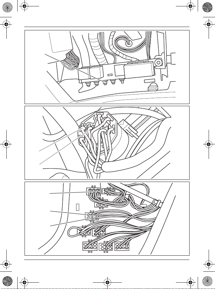
– die rote Leitung an die Schraubklemme „+30“ (unter dem Armaturenbrett,
Abb. 1 1, Seite 2)
– die orange Leitung an die Schraubklemme „75X“ (unter dem Armaturenbrett,
Abb. 1 1, Seite 2)
– die braune Leitung an einen vorhandenen Massepunkt
Audi A6
➤ Trennen Sie die Ringhülsen von folgenden Leitungen der Funk-Fernbedienung:
– rote Leitung
– orange Leitung
➤ Verbinden Sie die folgenden Leitungen der Funk-Fernbedienung jeweils mit
Hilfe von Schneidverbindern (Abb. 2, Seite 2):
– die rote Leitung mit der roten Leitung (rt) vom Zündschloss
– die orange Leitung mit der schwarz/gelben (sw/ge) Leitung vom Zündschloss
➤ Klemmen Sie die braune Leitung der Funk-Fernbedienung an einen vorhande-
nen Massepunkt an.
5
_MT200_AU3.book Seite 6 Montag, 19. April 2010 7:23 19
MT200 montieren und anschließen MagicTouch MT200 AU3
2.2 ZV-Ansteuerung und Blinkeransteuerung
Audi A4
Die Ansteuerung der Zentralverriegelung und der Blinker erfolgt an der A-Säule.
➤ Trennen Sie die gelb/blaue (ge/bl) bzw. grün/blaue (gn/bl) Originalleitung
(Abb. 3 1, Seite 2) Pin 5 aus dem braunen 10-poligen Stecker.
➤ Verbinden Sie die folgenden Leitungen der Funk-Fernbedienung wie
beschrieben (Abb. 3 1, Seite 2):
– die grau/rote Leitung mit der gelb/blaue (ge/bl) bzw. grün/blauen (gn/bl)
Originalleitung, die von der Zentralverriegelungspumpe kommt
– die gelb/blaue Leitung mit der anderen Seite der gelb/blaue (ge/bl) bzw.
grün/blauen (gn/bl) Originalleitung, die aus der Fahrzeugtür kommt
➤ Verbinden Sie die folgenden Leitungen der Funk-Fernbedienung jeweils mit
Hilfe von Schneidverbindern (Abb. 3, Seite 2):
– die schwarz/grüne Leitung mit der schwarz/grünen Leitung (sw/gn) aus
Pin 10 des braunen 10-poligen Steckers, der sich an der A-Säule befindet
– die schwarz/weiße Leitung mit der schwarz/weißen Leitung (sw/ws) aus
Pin 9 des braunen 10-poligen Steckers, der sich an der A-Säule befindet
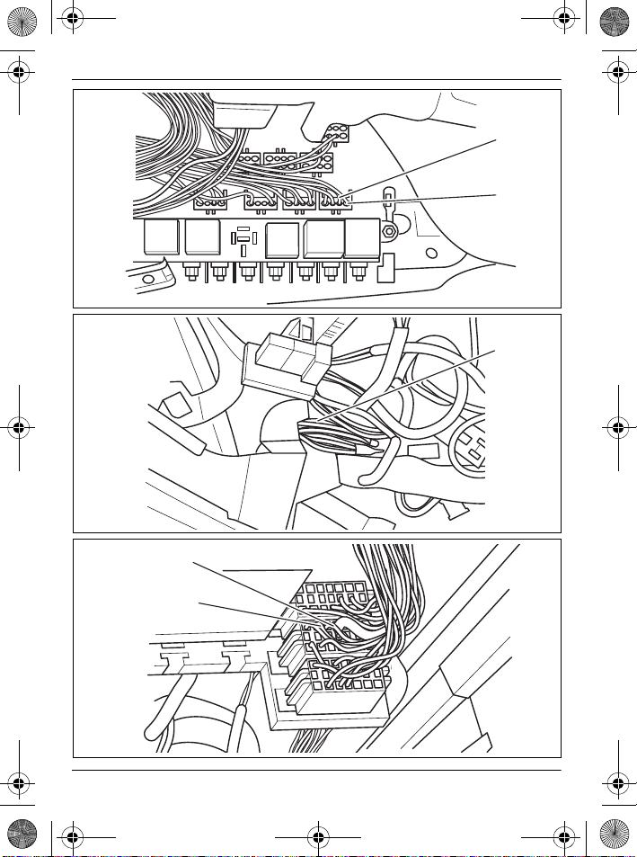
Audi A6
➤ Trennen Sie die gelb/blaue (ge/bl) bzw. grün/blaue (gn/bl) Originalleitung, die
aus der A-Säule kommt.
➤ Verbinden Sie die folgenden Leitungen der Funk-Fernbedienung wie
beschrieben (Abb. 5 1, Seite 3):
– die grau/rote Leitung mit der gelb/blaue (ge/bl) bzw. grün/blauen (gn/bl)
Originalleitung, die von der Zentralverriegelungspumpe kommt
– die gelb/blaue Leitung mit der anderen Seite der gelb/blaue (ge/bl) bzw.
grün/blauen (gn/bl) Originalleitung, die aus der Fahrzeugtür kommt
➤ Verbinden Sie die folgenden Leitungen der Funk-Fernbedienung jeweils mit
Hilfe von Schneidverbindern (Abb. 4, Seite 3):
– die schwarz/grüne Leitung mit der schwarz/grünen Leitung (sw/gn) aus dem
blauen 3-poligen Stecker, der sich oberhalb des Sicherungskastens befindet
– die schwarz/weiße Leitung mit der schwarz/weißen Leitung (sw/ws) aus dem
blauen 3-poligen Stecker, der sich oberhalb des Sicherungskastens befindet
6
_MT200_AU3.book Seite 7 Montag, 19. April 2010 7:23 19
MagicTouch MT200 AU3 MT200 montieren und anschließen
2.3 Montage abschließen
➤ Klemmen Sie das Masseband am Minuspol der Fahrzeugbatterie wieder an.
➤ Testen Sie die Funktion der Funk-Fernbedienung.
HINWEIS
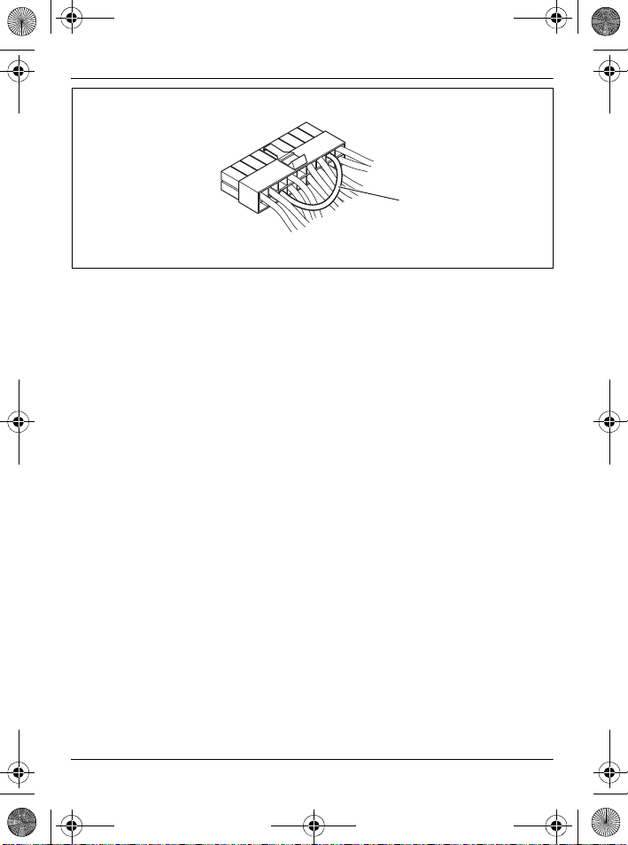
Vor dem Trennen der Kabelbrücke den Stecker ziehen!
I
Am Stecker des Kabelsatzes steckt zwischen Pin 7 und Pin 11 eine Kabelbrücke (Abb. 7 1, Seite 4):
z Kabelbrücke geschlossen (Werkszustand): für elektrische Stellmotore
(Ansteuerungszeit: 0,7 s)
z Kabelbrücke offen: für pneumatische Stellmotore (Ansteuerungszeit:
3s)
➤ Befestigen Sie das Steuergerät mit dem beiliegenden Befestigungsmaterial.
➤ Montieren Sie demontierte Verkleidungen/Abdeckungen wieder.
7
_MT200_AU3.book Seite 8 Montag, 19. April 2010 7:23 19
Suitable for installing in the following vehicles MagicTouch MT200 AU3
The following information contains vehicle-specific installation instructions
for MagicTouch MT200. Refer to the installation and operating manual for any
further information.
1 Suitable for installing in the following vehicles
The MagicTouch MT200 AU3 radio remote control (item no. 9101300027) can be
used in the following vehicle types:
z Audi A4 without TWS 95 – 97
z Audi A6 without TWS 94 – 97
TWS: theft warning system
2 Installing and connecting the MT200
NOTE
Use a red piercing connector for cables with a cross-section of max. 1 mm².
I
Use a blue piercing connector for cables with a cross-section of between
1.5 to 2.5 mm².
➤ Undo the strap on the negative terminal of the vehicle battery.
2.1 Power supply
Audi A4, A6
➤ Connect the following cables of the radio remote control as follows:
– Connect the red cable to the “+30” screw terminal (under the dashboard,
fig. 1 1, page 2)
– Connect the orange cable to the “75X” screw terminal (under the dashboard,
fig. 1 1, page 2)
– Connect the brown cable to an available earth point
Audi A6
➤ Disconnect the ring sleeves from the following cables of the radio remote con-
trol:
– Red cable
– Orange cable
➤ Connect the following cables of the radio remote control using piercing connec-
tors (fig. 2, page 2):
– Connect the red cable with the red cable (rt) from the ignition socket
– Connect the orange cable with the black/yellow (sw/ge) cable from the igni-
tion socket
➤ Connect the brown cable of the radio remote control to an available earth point.
8
_MT200_AU3.book Seite 9 Montag, 19. April 2010 7:23 19
MagicTouch MT200 AU3 Installing and connecting the MT200
2.2 CL and indicator activation
Audi A4
Activation of the central locking and the indicators is performed at the A pillar.
➤ Disconnect the yellow/blue (ge/bl) or green/blue (gn/bl) original cable (fig. 3 1,
page 2) of pin 5 of the brown, 10-pin plug.
➤ Connect the following cables of the radio remote control as described (fig. 3 1,
page 2):
– Connect the grey/red cable to the yellow/blue (ge/bl) or green/blue (gn/bl)
original cable which runs from the central locking pump
– Connect the yellow/blue cable to the yellow/blue (ge/bl) or green/blue (gn/bl)
original cable which runs from the vehicle door
➤ Connect the following cables of the radio remote control using piercing connec-
tors (fig. 3, page 2):
– Connect the black/green cable to the black/green cable (sw/gn) from pin 10
of the brown, 10-pin plug which is located on the A pillar
– Connect the black/white cable to the black/white cable (sw/ws) from pin 9 of
the brown, 10-pin plug which is located on the A pillar
Audi A6
➤ Disconnect the yellow/blue (ge/bl) or green/blue (gn/bl) original cable which
runs from the A pillar.
➤ Connect the following cables of the radio remote control as described (fig. 5 1,
page 3):
– Connect the grey/red cable to the yellow/blue (ge/bl) or green/blue (gn/bl)
original cable which runs from the central locking pump
– Connect the yellow/blue cable to the yellow/blue (ge/bl) or green/blue (gn/bl)
original cable which runs from the vehicle door
➤ Connect the following cables of the radio remote control using piercing connec-
tors (fig. 4, page 3):
– Connect the black/green cable to the black/green cable (sw/gn) of the blue,
3-pin plug which is located above the fuse box
– Connect the black/white cable to the black/white cable (sw/ws) of the blue,
3-pin plug which is located above the fuse box
9
_MT200_AU3.book Seite 10 Montag, 19. April 2010 7:23 19
Installing and connecting the MT200 MagicTouchM T200 AU3
2.3 Completing installation
➤ Reattach the strap on the negative terminal of the vehicle battery again.
➤ Test the radio remote control to see if it works correctly.
NOTE
Pull the plug out before disconnecting the cable bridge.
I
There is a cable bridge (fig. 7 1, page 4) on the plug of the cable set between pin 7 and pin 11:
z Cable bridge closed (factory setting): for electric servo motors (activation
time: 0.7 s)
z Cable bridge open: for pneumatic servo motors (activation time: 3 s)
➤ Fasten the control device in place using the fastening material supplied.
➤ Remount the panels and covers removed.
10
_MT200_AU3.book Seite 11 Montag, 19. April 2010 7:23 19
MagicTouch MT200 AU3 Convient pour le montage dans les véhicules suivants
Vous trouverez ci-après les instructions de montage spécifiques à la
MagicTouch MT200. Pour de plus amples informations, reportez-vous aux
instructions de montage et de service.
1 Convient pour le montage dans les véhicules sui-
vants
La télécommande radio MagicTouch MT200 AU3 (réf. 9101300027) peut être utilisée dans les types de véhicules suivants :
z Audi A4 sans PAV 95 – 97
z Audi A6 sans PAV 94 – 97
PAV : Protection antivol
2 Montage et raccordement de la MT200
REMARQUE
Pour les câbles d'une section maximale de 1 mm², utilisez les connecteurs
I
à lames rouges.
Pour les câbles d'une section maximale de 1,5 à 2,5 mm², utilisez les connecteurs à lames bleues.
➤ Débranchez la tresse de masse reliée au pôle négatif de la batterie du véhicule.
2.1 Alimentation électrique
Audi A4, A6
➤ A l'aide de connecteurs à lames, raccordez les câbles suivants de la télécom-
mande radio comme indiqué :
– le câble rouge à la borne à vis « +30 » (sous le tableau de bord, fig. 1 1,
page 2)
– le câble orange à la borne à vis « 75X » (sous le tableau de bord, fig. 1 1,
page 2)
– le câble marron à un point de masse existant
Audi A6
➤ Coupez les gaines des câbles suivants de la télécommande radio :
– câble rouge
– câble orange
➤ A l'aide de connecteurs à lames, raccordez les câbles suivants de la télécom-
mande radio (fig. 2, page 2) :
– le câble rouge au câble rouge (rt) de la serrure de contact
– le câble orange au câble noir/jaune (sw/ge) de la serrure de contact
➤ Raccordez le câble marron de la télécommande radio à un point de masse exis-
tant.
11