

Waeco EasyCool EC-1500-AC, EasyCool EC-2000-AC, EasyCool EC-1500-AC/DC, EasyCool EC-2000-AC/DC Installation And Operating Manual
Page 1

ec_1500_2000.book Seite 1 Freitag, 12. Mai 2006 4:11 16
EC-1500-AC, EC-1500-AC/DC,
EC-2000-AC, EC-2000-AC/DC
DE 9 Dachklimaanlage
Einbau- und Bedienungsanleitung
EN 37 Air conditioning roof unit
Installation and operating manual
FR 65 Climatiseur de toit
Notice de montage et d’utilisation
ES 93 Aire acondicionado de techo
Instrucciones de montaje y uso
IT 121 Climatizzatore a tetto
Istruzioni per I’uso e il montaggio
NL 149 Airconditioning voor dakinbouw
DA 177 Klimaanlæg til tagmontering
SV 205 Takmonterad klimatanläggning
NO 233 Takmontert klimaanlegg
FI 261 Kattooilmastointilaitteisto
Montagehandleiding en gebruiksaanwijzing
Installations- og betjeningsvejledning
Monterings- och bruksanvisning
Montasje- og bruksanvisning
Asennus- ja käyttöohje
Page 2

ec_1500_2000.book Seite 2 Freitag, 12. Mai 2006 4:11 16
Page 3

ec_1500_2000.book Seite 3 Freitag, 12. Mai 2006 4:11 16
1
2
3
3
Page 4

ec_1500_2000.book Seite 4 Freitag, 12. Mai 2006 4:11 16
4
5
6
B
A
4
Page 5

ec_1500_2000.book Seite 5 Freitag, 12. Mai 2006 4:11 16
7
A
B
C
8
9
D
EE
ABC
EE
5
Page 6

ec_1500_2000.book Seite 6 Freitag, 12. Mai 2006 4:11 16
10
6
5
4
11
1
1 32
2 3
6
Page 7

ec_1500_2000.book Seite 7 Freitag, 12. Mai 2006 4:11 16
12
7
Page 8

ec_1500_2000.book Seite 8 Freitag, 12. Mai 2006 4:11 16
13
17
(ge)
(br)
19
20
21
18
22
(bl)
(rt)
(sw)
16 23
15
14
(bl)
(bl)
(bl)
(bl)
13
9
10
7
8
2
(bl)
(br)
(rt)
(gn)
(sw)
3
(bl)
11
(ge)
4
(ge)
12
(br)
(bl)
(sw)
5
6
(br)
(bl)
(bl)
(br)
1
8
Page 9

ec_1500_2000.book Seite 9 Freitag, 12. Mai 2006 4:11 16
Inhaltsverzeichnis
1 Sicherheitshinweise . . . . . . . . . . . . . . . . . . . . . . . . . . . . . . . . . . . . . . . . . . . . . . . . . 10
1.1 Umgang mit der Anlage . . . . . . . . . . . . . . . . . . . . . . . . . . . . . . . . . . . . . . . . . 10
2 Handbuchkonventionen. . . . . . . . . . . . . . . . . . . . . . . . . . . . . . . . . . . . . . . . . . . . . . 11
2.1 Allgemeine Informationen zum Handbuch . . . . . . . . . . . . . . . . . . . . . . . . . . . 11
2.2 Zielgruppe . . . . . . . . . . . . . . . . . . . . . . . . . . . . . . . . . . . . . . . . . . . . . . . . . . . . 11
2.3 Symbole und Formate . . . . . . . . . . . . . . . . . . . . . . . . . . . . . . . . . . . . . . . . . . . 12
3 Bestimmungsgemäßer Gebrauch . . . . . . . . . . . . . . . . . . . . . . . . . . . . . . . . . . . . . . 13
4 Technische Beschreibung . . . . . . . . . . . . . . . . . . . . . . . . . . . . . . . . . . . . . . . . . . . . 13
4.1 Gerätevariationen . . . . . . . . . . . . . . . . . . . . . . . . . . . . . . . . . . . . . . . . . . . . . . 13
4.2 Lieferumfang . . . . . . . . . . . . . . . . . . . . . . . . . . . . . . . . . . . . . . . . . . . . . . . . . . 14
4.3 Funktionsweise . . . . . . . . . . . . . . . . . . . . . . . . . . . . . . . . . . . . . . . . . . . . . . . . 15
4.4 Kennzeichnungsschilder . . . . . . . . . . . . . . . . . . . . . . . . . . . . . . . . . . . . . . . . . 16
4.5 Stückliste . . . . . . . . . . . . . . . . . . . . . . . . . . . . . . . . . . . . . . . . . . . . . . . . . . . . . 17
4.6 Schaltplan . . . . . . . . . . . . . . . . . . . . . . . . . . . . . . . . . . . . . . . . . . . . . . . . . . . . 18
5 Installation. . . . . . . . . . . . . . . . . . . . . . . . . . . . . . . . . . . . . . . . . . . . . . . . . . . . . . . . . 19
5.1 Hinweise zur Installation . . . . . . . . . . . . . . . . . . . . . . . . . . . . . . . . . . . . . . . . . 19
5.2 Installationschritte . . . . . . . . . . . . . . . . . . . . . . . . . . . . . . . . . . . . . . . . . . . . . .21
6 Bedienung . . . . . . . . . . . . . . . . . . . . . . . . . . . . . . . . . . . . . . . . . . . . . . . . . . . . . . . . . 25
6.1 Kontrolle vor Inbetriebnahme . . . . . . . . . . . . . . . . . . . . . . . . . . . . . . . . . . . . . 26
6.2 Einstellung der Luftdüsen . . . . . . . . . . . . . . . . . . . . . . . . . . . . . . . . . . . . . . . . 26
6.3 Einschalten der Dachklimaanlage . . . . . . . . . . . . . . . . . . . . . . . . . . . . . . . . . . 26
6.4 Umschalten auf Kühlbetrieb . . . . . . . . . . . . . . . . . . . . . . . . . . . . . . . . . . . . . . 26
6.5 Umschalten auf Heizbetrieb . . . . . . . . . . . . . . . . . . . . . . . . . . . . . . . . . . . . . . 26
6.6 Ändern der Kühl-/Heizleistung . . . . . . . . . . . . . . . . . . . . . . . . . . . . . . . . . . . . 27
6.7 Auswählen der Gebläsestufen . . . . . . . . . . . . . . . . . . . . . . . . . . . . . . . . . . . . 27
7 Wartung und Pflege . . . . . . . . . . . . . . . . . . . . . . . . . . . . . . . . . . . . . . . . . . . . . . . . . 28
8 Entsorgung . . . . . . . . . . . . . . . . . . . . . . . . . . . . . . . . . . . . . . . . . . . . . . . . . . . . . . . . 28
8.1 Verpackungsmaterial entsorgen . . . . . . . . . . . . . . . . . . . . . . . . . . . . . . . . . . . 28
8.2 Altgerät entsorgen . . . . . . . . . . . . . . . . . . . . . . . . . . . . . . . . . . . . . . . . . . . . . . 28
9 Störungsbeseitigung . . . . . . . . . . . . . . . . . . . . . . . . . . . . . . . . . . . . . . . . . . . . . . . . 29
10 Wechselrichter . . . . . . . . . . . . . . . . . . . . . . . . . . . . . . . . . . . . . . . . . . . . . . . . . . . . . 30
10.1 Allgemeine Sicherheits- und Einbauhinweise . . . . . . . . . . . . . . . . . . . . . . . . . 30
10.2 Bestimmungsgemäßer Gebrauch . . . . . . . . . . . . . . . . . . . . . . . . . . . . . . . . . . 31
10.3 Funktionsweise . . . . . . . . . . . . . . . . . . . . . . . . . . . . . . . . . . . . . . . . . . . . . . . . 31
10.4 Installation des Wechselrichters . . . . . . . . . . . . . . . . . . . . . . . . . . . . . . . . . . . 31
10.5 Funktionstest des Wechselrichters ECW-012VS . . . . . . . . . . . . . . . . . . . . . . 33
10.6 Störungsanzeige . . . . . . . . . . . . . . . . . . . . . . . . . . . . . . . . . . . . . . . . . . . . . . . 34
11 Ladestromverteiler . . . . . . . . . . . . . . . . . . . . . . . . . . . . . . . . . . . . . . . . . . . . . . . . . . 34
11.1 Verwendungszweck . . . . . . . . . . . . . . . . . . . . . . . . . . . . . . . . . . . . . . . . . . . . 34
11.2 Funktionsweise . . . . . . . . . . . . . . . . . . . . . . . . . . . . . . . . . . . . . . . . . . . . . . . . 34
12 Technische Daten . . . . . . . . . . . . . . . . . . . . . . . . . . . . . . . . . . . . . . . . . . . . . . . . . . . 35
9
Page 10

ec_1500_2000.book Seite 10 Freitag, 12. Mai 2006 4:11 16
Sicherheitshinweise
1 Sicherheitshinweise
Es ist zwingend notwendig, den gesamten Inhalt des Handbuches
aufmerksam zulesen.
Nur wenn den Anleitungen Folge geleistet wird, kann ein einwandfreier
Betrieb, Zuverlässigkeit der Dachklimaanlage und Schutz vor Personenoder Sachschäden erfolgen.
WAECO International übernimmt keine Haftung für Schäden aufgrund folgender Punkte:
Montagefehler,
Beschädigungen am System durch mechanische Einflüsse und Über-
spannungen,
Veränderungen am Gerät ohne ausdrückliche Genehmigung von
WAECO International,
Verwendung für andere als die in der Einbauanleitung beschriebenen
Zwecke.
1.1 Umgang mit der Anlage
Benutzen Sie die Dachklimaanlage nur für den vom Hersteller
angegebenen Verwendungszweck und führen Sie keine Änderungen
oder Umbauten am Gerät durch!
Betreiben Sie die Dachklimaanlage nur, wenn das Gehäuse und die
Leitungen nicht beschädigt sind!
Lösen Sie bei Arbeiten an der Anlage alle Verbindungen zur
Stromversorgung!
Die Dachklimaanlage muss so sicher installiert werden, dass diese nicht
umstürzen oder herabfallen kann!
Schützen Sie die Anlage vor Dreck und Staub!
Fahren Sie mit der Dachklimaanlage nicht in eine Waschstraße!
10
Die Installation, Wartung und etwaige Reparatur dürfen nur durch einen
Fachbetrieb erfolgen, der mit den damit verbundenen Gefahren bzw.
einschlägigen Vorschriften vertraut ist!
Achten Sie darauf, dass brennbare Gegenstände nicht im Bereich des
Luftaustrittes gelagert bzw. montiert sind. Der Abstand muss
mindestens 50 cm betragen!
Setzen Sie die Dachklimaanlage nicht in der Nähe von entflammbaren
Flüssigkeiten oder in geschlossenen Räumen ein.
Greifen Sie nicht in Lüftungsgitter oder Lüftungsdüsen, und führen Sie
keine Fremdgegenstände in die Anlage.
Im Falle von Feuer lösen Sie nicht den oberen Deckel der
Dachklimaanlage, sondern verwenden Sie zugelassene Löschmittel.
Verwenden Sie kein Wasser zum Löschen.
Page 11

ec_1500_2000.book Seite 11 Freitag, 12. Mai 2006 4:11 16
1.1.1 Umgang mit elektrischen Leitungen
Müssen Leitungen durch scharfkantige Wände geführt werden, so
verwenden Sie Leerrohre bzw. Leitungsdurchführungen!
Verlegen Sie keine losen oder scharf abgeknickten Leitungen an
elektrisch leitenden Materialien (Metall)!
Ziehen Sie nicht an Leitungen!
Befestigen und verlegen Sie Leitungen so, dass keine Stolpergefahr
entsteht und eine Beschädigung des Kabel ausgeschlossen ist.
Verwenden Sie stets geerdete und durch FS-Schalter gesicherte
Steckdosen.
Der elektrische Anschluss darf nur von einem Fachbetrieb durchgeführt
werden (z.B. in Deutschland -VDE 0100, Teil 721).
Handbuchkonventionen
Sichern Sie den Anschluss ans Netz im Fahrzeug mit mindestens
10 Ampere ab.
2 Handbuchkonventionen
2.1 Allgemeine Informationen zum Handbuch
Dieses Handbuch enthält die wesentlichen Informationen und Anleitungen
für den sachgemäßen Gebrauch und die Installation der Dachklimaanlage.
Die enthaltenen Informationen richten sich sowohl an den Benutzer als,
auch den Installationsbetrieb der Dachklimaanlage.
Folgende Hinweise helfen Ihnen bei der korrekten Anwendung des
Handbuches:
Das Handbuch ist Teil des Lieferumfangs und ist sorgfältig
aufzubewahren.
Der in diesem Handbuch geschilderte, richtige Gebrauch gewährleistet
einen wirtschaftlichen Betrieb und eine längere Lebensdauer des
Geräts.
Die Einbauanleitung gibt Ihnen wichtige Hinweise für die Montage und
dient gleichzeitig in Reparaturfällen als Nachschlagewerk.
Bei Nichtbeachtung dieser Einbau- und Bedienungsanleitung haftet der
Hersteller (WAECO) nicht. Jegliche Ansprüche sind für diesen Fall
ausgeschlossen.
2.2 Zielgruppe
Installationsinformationen (siehe Kapitel „Installation” auf Seite 19) in
dieser Anleitung richten sich an Facharbeiter in Werkstätten, die mit den
anzuwenden Richtlinien und Sicherheitsvorkehrungen vertraut sind.
Informationen zum Gerät (Bedienungshinweise, Umgang mit dem
Gerät, Sicherheitshinweise usw.) richten sich an den Anwender der
Dachklimaanlage.
11
Page 12

ec_1500_2000.book Seite 12 Freitag, 12. Mai 2006 4:11 16
Handbuchkonventionen
2.3 Symbole und Formate
In dieser Dokumentation werden Ihnen Symbole und Formate begegnen.
Diese haben folgende Bedeutung:
Format Bedeutung Beispiel
Fett Wichtige Informationen im Text,
die nicht missverstanden werden
dürfen
➤
✓ Ergebnisse eines
Handlungsanleitende Texte
Handlungsschrittes
Schalter (3) auf Symbol
KÜHLEN stellen.
➤ Entfernen Sie den Plus (+)
Pol Anschluss von der
Versorgungsbatterie.
✓ Die Anlage ist nun
betriebsbereit.
Hinweis auf:
mögliche Verletzungsrisiken für den Installateur oder den Anwender
und
mögliche Gerätebeschädigung.
Zeigt eine mögliche Gefahrensituation an, die während der Montage bzw.
im Betrieb des Produkts entstehen könnte und Schäden am Gerät bzw.
eine Umweltschädigung oder wirtschaftliche Schäden verursachen kann.
Besondere Informationen zum Umgang mit dem Produkt.
12
Page 13

ec_1500_2000.book Seite 13 Freitag, 12. Mai 2006 4:11 16
3 Bestimmungsgemäßer Gebrauch
Die Dachklimaanlagen sind in der Lage die Innenräume von Fahrzeugen
mit warmer bzw. kalter Luft zu heizen oder zu kühlen.
Die Dachklimaanlagen sind nicht für die Installation in Baumaschinen,
Landmaschinen oder ähnlichen Arbeitsgeräten geeignet. Bei zu starker
Vibrationseinwirkung ist eine ordnungsgemäße Funktion nicht
gewährleistet.
Die Dachklimaanlagen sind für eine Umgebungstemperatur unter 43 °C im
Kühlbetrieb bzw. unter 30 °C Raumtemperatur im Heizbetrieb ausgelegt.
Bestimmungsgemäßer Gebrauch
Die Dachklimaanlagen EC-1500-AC, EC-2000-AC, EC-1500-AC/DC und
EC-2000-AC/DC von WAECO wurden für die Installation in Fahrzeugdächer entwickelt (siehe Abb. 1 auf Seite 3).
Nur für AC/DC-Versionen: Nutzen Sie niemals den Heizbetrieb bzw. den
Automatikbetrieb der Anlage während der Fahrklimatisierung (12 V DC).
Der verwendete Wechselrichter ist für diese Funktion nicht ausgelegt und
Sie könnten so den Wechselrichter beschädigen.
4 Technische Beschreibung
Der Betrieb der Dachklimaanlage mit Spannungswerten, die von den
angegebenen Werten abweichen, führt zur Beschädigung des Gerätes.
Deshalb unbedingt beachten: Vor dem Betrieb der Dachklimaanlage
müssen Sie die Spannung überprüfen (insbesondere vor dem Betrieb auf
Campingplätzen etc.).
4.1 Gerätevariationen
Je nach Ausführung der Dachklimaanlage sind die Geräte für die
Standklimatisierung (EC-1500-AC und EC-2000-AC) oder auch für die
Stand- und Fahrklimatisierung (EC-1500-AC/DC und EC-2000-AC/DC)
geeignet. Die genauen Spezifikationen Ihres Gerätes finden Sie im Kapitel
„Technische Daten” auf Seite 35.
13
Page 14

ec_1500_2000.book Seite 14 Freitag, 12. Mai 2006 4:11 16
Technische Beschreibung
Nur AC/DC-Versionen: Stehen der Dachklimaanlage zur Stand- und
Fahrklimatisierung beide Stromquellen – Fahrzeugbatterie (12 V) und
Festnetz (230 V/50 Hz) – zur Verfügung, so wird durch eine
Vorrangsschaltung immer die 230-V-Stromversorgung gewählt.
4.2 Lieferumfang
EC-1500-AC
Teilebezeichnung Artikelnummer
Dachklimaanlage EC-1500-AC EC-1500-AC
Schuko-Netzkabel 4441300041
Befestigungsrahmen 4442500090
Abdeckrahmen 4443000049
Formdichtung 4443300010
Montagematerial
Bedienungsanleitung Dachklimaanlage 4445100104
EC-2000-AC
Teilebezeichnung Artikelnummer
Dachklimaanlage EC-2000-AC EC-2000-AC
Schuko-Netzkabel 4441300041
Befestigungsrahmen 4442500090
Abdeckrahmen 4443000049
Formdichtung 4443300010
Montagematerial
Bedienungsanleitung Dachklimaanlage 4445100104
EC-1500-AC/DC
Teilebezeichnung Artikelnummer
Dachklimaanlage EC-1500-AC/DC EC-1500-AC/DC
Schuko-Netzkabel 4441300041
Befestigungsrahmen 4442500090
Abdeckrahmen 4443000049
Formdichtung 4443300010
Wechselrichter ECW-012VS
Ladestromverteiler ECL-75
Montagematerial
Bedienungsanleitung Dachklimaanlage 4445100104
Bedienungsanleitung Ladestromverteiler 4445100087
14
Page 15

ec_1500_2000.book Seite 15 Freitag, 12. Mai 2006 4:11 16
EC-2000-AC/DC
Teilebezeichnung Artikelnummer
Dachklimaanlage EC-2000-AC/DC EC-2000-AC/DC
Schuko-Netzkabel 4441300041
Befestigungsrahmen 4442500090
Abdeckrahmen 4443000049
Formdichtung 4443300010
Wechselrichter ECW-012VS
Ladestromverteiler ECL-100
Montagematerial
Bedienungsanleitung Dachklimaanlage 4445100104
Bedienungsanleitung Ladestromverteiler 4445100087
4.3 Funktionsweise
Technische Beschreibung
Es kann mit Hilfe der Dachklimaanlagen eine variable Klimatisierung eines
Fahrzeuginnenraums erfolgen.
Die Anlage ist in der Lage die Temperatur im Innenraum des Fahrzeugs
auf einen bestimmten Wert ab- bzw. aufzuheizen. Die zu erreichende
Temperatur beim Kühlen hängt von dem Fahrzeugtyp, der Umgebungstemperatur und der Kälteleistung Ihrer Klimaanlage ab. Zur Kälteleistung
Ihrer Klimaanlage siehe Kapitel „Technische Daten” auf Seite 35.
Der Kältekreislauf der Dachklimaanlage besteht aus vier
Hauptkomponeten:
Kompressor
Der Kompressor saugt das eingesetzte Kältemittel R407c an und
verdichtet es. Somit werden Druck und dadurch auch die Temperatur
des Kältemittels erhöht.
Kondensator
Der eingebaute Kondensator funktioniert wie ein Kühler bzw. ein
Wärmetauscher. Die vorbeiströmende Luft nimmt Wärme auf, das heiße
Kältemittelgas kühlt ab und kondensiert. Das Kältemittel wird flüssig.
Verdampfer
Der Verdampfer kühlt die vorbeiströmende Luft ab und entfeuchtet sie.
Das Kältemittel nimmt Wärme auf. Die abgekühlte Luft wird im
Fahrzeuginneren über eine Luftauslasseinheit verteilt.
Bei niedrigen Temperaturen besteht die Möglichkeit die ausströmende Luft
zu erwärmen. Hierzu wird die angesaugte Luft über eine elektrische
Widerstandsheizung aufgewärmt. Ein Thermostat sorgt für die
Regulierung der Lufttemperatur.
15
Page 16

ec_1500_2000.book Seite 16 Freitag, 12. Mai 2006 4:11 16
Technische Beschreibung
4.4 Kennzeichnungsschilder
An den Dachklimaanlagen EC-1500-AC, EC-2000-AC, EC-1500-AC/DC
und EC-2000-AC/DC von WAECO sind Kennzeichnungsschilder
angebracht. Diese Kennzeichnungsschilder informieren den Anwender
und den Installateur über Gerätespezifikationen.
(1) (2)
Produktgruppe/Range : Easy Cool
Artikel-Nr./Art-No. : EC-1500-AC
Version/version : XXX
Serien-Nr./Series-No. : XXX
Inhalt/Volume :
Anschlußspannung/
Operation Voltage
Nennleistung/Power-Rating : 900 W hot
Nennleistung/Power-Rating : 900 W cold
Kältemittel/Refrigerant : R 407c / 400 g
Max. Druck/Max. Pressure : ND 11 bar / HD 30 bar
Klimaklasse/Climatic class : N
WAECO – Made in Germany
:
: AC 230 V ~ / 50 Hz
Produktgruppe/Range : Easy Cool
Artikel-Nr./Art-No. : EC-1500-AC/DC
Version/version : XXX
Serien-Nr./Series-No. : XXX
Inhalt/Volume :
Anschlußspannung/
Operation Voltage
Nennleistung/Power-Rating : 900 W hot
Nennleistung/Power-Rating : 900 W cold
Kältemittel/Refrigerant : R 407c / 400 g
Max. Druck/Max. Pressure : ND 11 bar / HD 30 bar
Klimaklasse/Climatic class : N
WAECO – Made in Germany
:
: AC 230 V ~ / 50 Hz
(3) (4)
Produktgruppe/Range : Easy Cool
Artikel-Nr./Art-No. : EC-2000-AC
Version/version : XXX
Serien-Nr./Series-No. : XXX
Inhalt/Volume :
Anschlußspannung/
Operation Voltage
Nennleistung/Power-Rating : 1300 W hot
Nennleistung/Power-Rating : 1200 W cold
Kältemittel/Refrigerant : R 407c / 400 g
Max. Druck/Max. Pressure : ND 11 bar / HD 30 bar
Klimaklasse/Climatic class : N
WAECO – Made in Germany
:
: AC 230 V ~ / 50 Hz
Produktgruppe/Range : Easy Cool
Artikel-Nr./Art-No. : EC-2000-AC/DC
Version/version : XXX
Serien-Nr./Series-No. : XXX
Inhalt/Volume :
Anschlußspannung/
Operation Voltage
Nennleistung/Power-Rating : 1300 W hot
Nennleistung/Power-Rating : 1200 W cold
Kältemittel/Refrigerant : R 407c / 400 g
Max. Druck/Max. Pressure : ND 11 bar / HD 30 bar
Klimaklasse/Climatic class : N
WAECO – Made in Germany
:
: AC 230 V ~ / 50 Hz
16
Page 17

ec_1500_2000.book Seite 17 Freitag, 12. Mai 2006 4:11 16
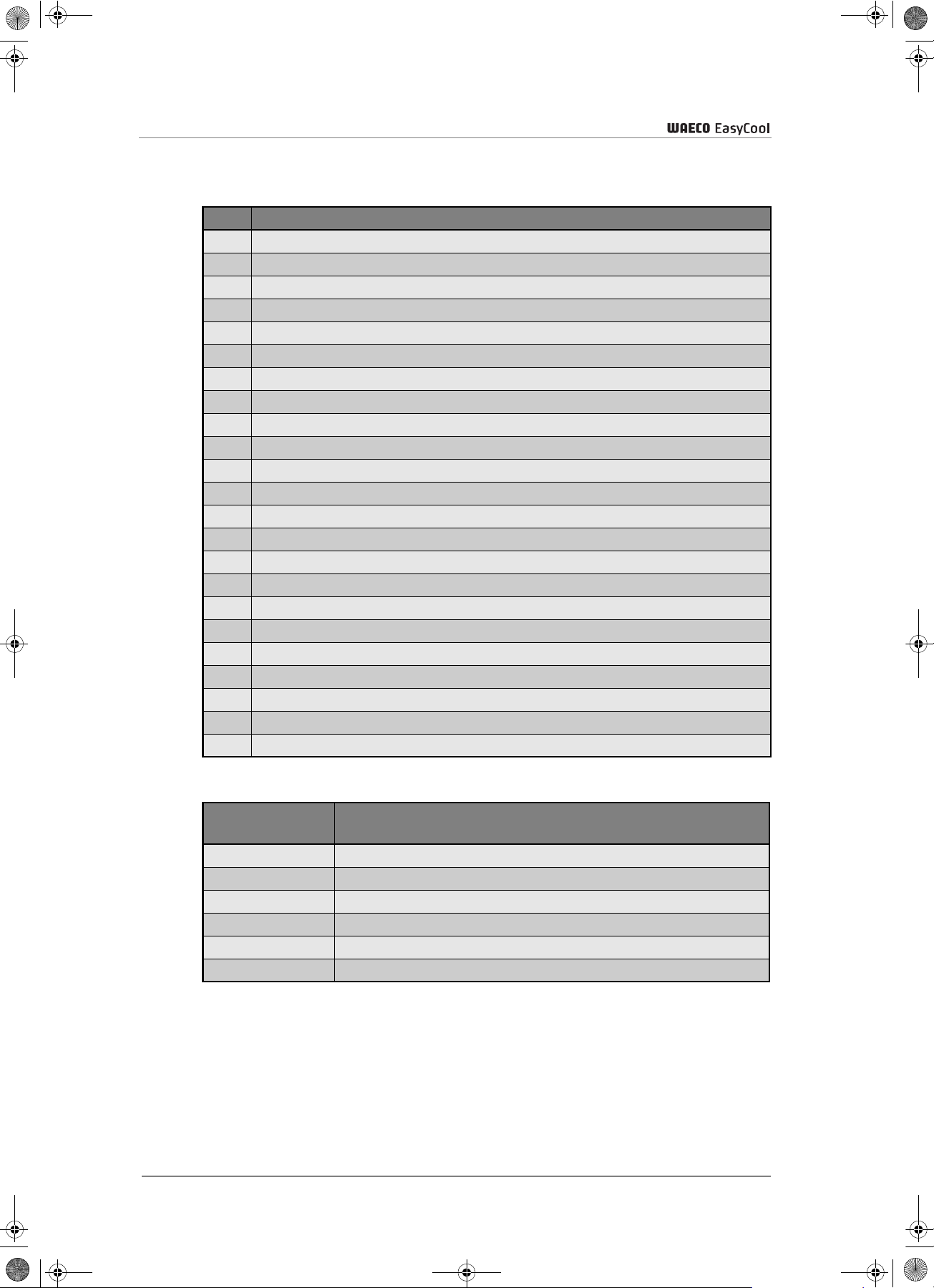
4.5 Stückliste
– siehe Abb. 12 auf Seite 7 –
Nr. Menge Bezeichnung
1 1 Gehäuse-Oberteil EC
2 1 Umluftgehäuse EC
3 1 Luftführungskasten EC
4 1 Heizelement
5 1 Zugentlastung groß (Elektrokabel 230 V)
6 1 Zugentlastung klein (Sensorkabel)
7 1 Platine -Steuerung EC
8 1 Betriebskondensator
9 1 Anlaufkondensator
10 1 Kabeldurchführung EC 4443200023/Teil 1
11 1 Befestigungsschelle Betriebskondensator EC
12 1 Befestigungsschelle Anlaufkondensator EC
13 1 Startrelais EC
14 1 Wasserablauf, Kondensator rechts EC 4443200023/Teil 3
15 8 Reduzierstück EC
16 2 Verbindungsschlauch EC (lang, 45 cm gestreckt gemessen)
17 2 Verbindungsschlauch EC (kurz, 25 cm gestreckt gemessen)
18 1 Formdichtung Kabinendach EC
19 1 Befestigungsrahmen EC
20 1 Abdeckrahmen EC
21 1 Bedieneinheit EC
22 1 Umluftfilter EC, Grob
23 1 Schalter, Heizung-Kühlung EC (mit Bedruckung Heizen-Kühlen)
24 1 Hauptschalter EC
25 1 Lüfterschalter EC
26 4 Luftaustrittsdüsen EC
27 1 Thermostatknopf EC
28 1 Luftansauggitter EC
29 1 Thermostat EC
30 1 Moosgummiplatte Kabinendach EC
31 1 Gehäuse-Unterteil EC
32 1 Kondensatorlüfter EC
33 1 Lufthutze EC
34 1 Kälteeinheit
35 1 Wasserablauf, Kondensator links EC 4443200023/Teil 2
36 1 Trafo 2 x 12V 225 Watt EC
37 2 Dichtung Kondensator
38 1 Sicherungshalter, Metall (Thermosicherung)
39 1 Stützhalter, Heizelement EC
40 1 Temperaturschalter u. Thermosicherung EC
41 1 Dichtung Kondensator (Gehäuseoberteil)
Technische Beschreibung
17
Page 18

ec_1500_2000.book Seite 18 Freitag, 12. Mai 2006 4:11 16
Technische Beschreibung
4.6 Schaltplan
– siehe Abb. 13 auf Seite 8 –
Nr. Bezeichnung
1 Transformator
2 Transformator Sek.
3 Kompressor
4 Trafo 230 V
5 E/A Schalter
6 230 V
7 ECC-1500
8 Inverter E/A
9 Verdampfer-Lüfter
10 Kondensator-Lüfter
11 Schalter
12 Heizungsschalter
13 Kompressor
14 Verdampfer-Lüfter
15 Nur EC-2000: Festpunkt-Thermostat
16 Temperatursicherung
17 Lüfter 1/2 (N)
18 Kondensator-Lüfter
19 Thermostat (R)
20 Kalt/Warm (S)
21 Ein/Aus (O)
22 Heizung
23 Temperaturbegrenzung
18
Leitungsfarben:
Bezeichnung in
Abb. 13
bl blau
rt rot
ge gelb
br braun
gn grün
sw schwarz
Farbe
Page 19

ec_1500_2000.book Seite 19 Freitag, 12. Mai 2006 4:11 16
5Installation
Die Installation der Dachklimaanlage darf ausschließlich nur von
entsprechend ausgebildeten Fachbetrieben durchgeführt werden. Die
nochfolgenden Informationen richten sich an Fachkräfte die mit den
anzuwendenen Richtlinien und Sicherheitsvorkehrungen vertraut sind.
5.1 Hinweise zur Installation
Vor der Installation der Dachklimaanlage muss diese Einbauanleitung
vollständig gelesen werden.
Folgende Tipps und Hinweise müssen bei der Installation der
Dachklimaanlage beachtet werden:
Installation
Unterbrechen Sie bei Arbeiten an der Dachklimaanlage alle
Stromversorgungen.
Nur für EC-1500-AC/DC und EC-2000-AC/DC:
Beachten Sie, dass auch der Wechselrichter ausgeschaltet ist und die
Stromversorgung unterbrochen ist.
Grundsätzlich ist vor Installation der Dachklimaanlage zu überprüfen, ob
durch den Einbau der Dachklimaanlage ggf. Fahrzeugkomponenten
beschädigt werden könnten (z.B. Lampen, Schränke, Türen etc.).
Vor Einbau müssen Sie – über den Fahrzeughersteller – klären, ob der
Aufbau für das statische Gewicht und die Belastungen durch die
Klimaanlage bei in Bewegung befindlichem Fahrzeug ausgelegt ist. Der
Hersteller der Dachklimaanlage (WAECO) übernimmt keinerlei Haftung.
Der Fahrzeughersteller hat eventuell bereits Stellen vorgesehen, an
denen die Öffnung zur Installation der Dachklimaanlage ohne Gefahr
der Schwächung des Aufbaus bzw. des Durchtrennen von Stromkabeln
eingebracht werden kann.
Wählen Sie als Montageort eine flache und ausreichend ebene Zone in
der Mitte des Fahrzeugdaches.
Achten Sie darauf, dass brennbare Gegenstände nicht im Bereich des
Luftaustrittes gelagert bzw. montiert sind. Der Abstand sollte
mindestens 50 cm betragen!
Stellen Sie sicher, dass im Fahrzeuginneren kein Hindernis für die
Befestigung der Luftverteilereinheit und das Austreten der gekühlten
und geheizten Luft über die schwenkbaren Luftverteilerdüsen vorliegt.
Achten Sie aus Sicherheitsgründen beim Einbau der Dachklimaanlage
(beim Bohren und Schrauben usw.) auf den Verlauf von vorhandenen,
insbesondere nicht sichtbaren Kabelsträngen, Leitungen und anderen
Komponenten, die sich im Montagebereich befinden!
19
Page 20
ec_1500_2000.book Seite 20 Freitag, 12. Mai 2006 4:11 16
Installation
Eine falsche Installation der Klimaanlage kann zu irreparablen Schäden
am Gerät führen und die Sicherheit des Benutzers beeinträchtigen.
Wenn die Dachklimaanlage nicht gemäß dieser Einbauanleitung installiert
wird übernimmt WAECO keinerlei Haftung, nicht für Betriebsstörungen
und für die Sicherheit der Dachklimaanlage, insbesondere nicht für
Personen- und/oder Sachschäden.
Vor der Installation der Dachklimaanlage sind folgende
Spannungsversorgungen des Fahrzeugs zu lösen:
Pluspol der Batterie
Externe Stromversorgung
(bei AC/DC-Versionen auch Stromversorgung des Wechselrichters).
Bei Nichtbeachten dieser Vorschrift besteht Stromschlaggefahr.
Für den Einbau der Klimaanlage können Sie zwei verschiedene Lösungen
wählen:
Anbringung einer neuen Öffnung (siehe Kapitel „Neue Einbauöffnung
herstellen” auf Seite 21). In diesem Fall muss in die neue Öffnung mit
einem geeigneter Rahmen verstärkt werden.
Verwendung der am Fahrzeug vorhandenen Dachlukenöffnungen
(Lüftungsluke) (siehe Kapitel „Einbau in eine vorhandene
Dachlukenöffnung” auf Seite 21).
Der Einbau der Dachklimaanlage muss durch einen entsprechend
ausgebildeten Fachbetrieb erfolgen. Alle obengenannten Punkte,
insbesondere alle Punkte der Statik, müssen über den Fahrzeughersteller
geklärt werden.
Bitte informieren Sie sich bei Ihrem Fahrzeughersteller, ob aufgrund des
Aufbaues der Dachklimaanlage eine Änderung des Eintrags der
Fahrzeughöhe in ihren Fahrzeugpapieren notwendig ist.
20
Page 21

ec_1500_2000.book Seite 21 Freitag, 12. Mai 2006 4:11 16
5.2 Installationschritte
Bevor Sie das Fahrzeugdach besteigen prüfen Sie, ob dieses für
Personen begehbar ist. Zulässige Dachlasten können Sie beim
Fahrzeughersteller erfragen.
5.2.1 Neue Einbauöffnung herstellen
– siehe Abb. 4 auf Seite 4 und siehe Abb. 5 auf Seite 4 –
Bohren Sie vor den Sägearbeiten die Ecken aus!
Setzen Sie zur Verstärkung der Einbauöffnung einen Rahmen aus
Holzleisten ein.
Installation
Beim Gebrauch von elektrischen Werkzeugen oder Handsägen müssen
Schutzbrille und Schutzhandschuhe getragen werden.
➤ Wählen Sie auf dem Dach eine Zone in der Mitte zwischen zwei
Längsprofilen.
➤ Markieren Sie mit einem Faserstift eine quadratische Öffnung von
400 mm.
➤ Schneiden Sie die Öffnung auf dem Dach sorgfältig mit einer
Stichsäge o.ä. aus. Achten Sie dabei darauf, dass keine elektrischen
Kabel beschädigt werden.
➤ Bringen Sie an einer Seite eine Öffnung für das Durchführen des
elektrischen Versorgungskabels an.
5.2.2 Einbau in eine vorhandene Dachlukenöffnung
– siehe Abb. 1 auf Seite 3 –
Der Einbau der Dachklimaanlage eignet sich in vorhandenen
Dachlukenöffnungen mit den Abmessungen 400 mm bis 435 mm. Sollte
die Öffnung zum Einbau der Anlage größer als 435 mm sein, so besteht
die Möglichkeit Mittels eines selbst hergestellten Rahmens den
Dachausschnitt zu verkleinern. Die Dachlukenöffnung beim Einbau der
Anlage mit Hilfsrahmen sollte höchstens 450 mm betragen.
21
Page 22

ec_1500_2000.book Seite 22 Freitag, 12. Mai 2006 4:11 16
Installation
WAECO International übernimmt ausschließlich Haftung für im
Lieferumfang enthaltene Teile. Beim Einbau der Anlage zusammen mit
produktfremden Teilen entfällt die Gewährleistungsgarantie.
Bitte Beachten Sie beim Einbau der Dachklimaanlage stets die Statik des
Fahrzeugs und die Abdichtung aller beim Einbau entstandenen
Öffnungen.
Dachluke entfernen
– siehe Abb. 2 auf Seite 3 und siehe Abb. 3 auf Seite 3 –
➤ Entfernen Sie alle Schrauben und Befestigungen der vorhandenen
Dachluke.
➤ Nehmen Sie die Dachluke heraus.
➤ Entfernen Sie das Dichtungsmaterial rund um die Öffnung mit einem
Schaber o. ä..
➤ Dichten Sie die Bohrungen mit Dichtungsmaterial ab.
Entsorgen Sie sämtliches Abfallmaterial, Leim, Silikon und Dichtungen
getrennt. Beachten Sie dabei die Entsorgungsrichtlinien.
5.2.3 Einstellen der Luftverteilereinheit
– siehe Abb. 6 auf Seite 4 –
Zum passgenauen Einbau der Dachklimaanlage, müssen Sie die Tiefe der
Luftverteilereinheit (siehe Abb. 7 auf Seite 5, Pos. A) an die Dachdicke
Ihres Fahrzeugs anpassen. Die Luftverteilereinheit (siehe Abb. 6 auf Seite
4, Pos. A) ist ab Werk für einen Einbau bei einer Dachdicke von ca.
38 mm bis 42 mm eingestellt. Bei dickeren bzw. dünneren Dächern,
müssen Sie die Luftverteilereinheit zum Befestigungsrahmen (siehe Abb. 6
auf Seite 4, Pos. B) der Anlage anpassen:
22
➤ Lösen Sie die 6 Befestigungsschrauben (siehe Abb. 6 auf Seite 4).
➤ Stellen Sie die benötigte Tiefe der Luftverteilereinheit ein.
Bitte beachten Sie beim Einstellen der Luftverteilereinheit, dass sich die
Dachklimaanlage beim Anziehen der Befestigungsschrauben noch um
ca. 8-10 mm nach unten bewegt.
➤ Nutzen Sie die vorgegebenen Bohrungen zum Fixieren der
Page 23

ec_1500_2000.book Seite 23 Freitag, 12. Mai 2006 4:11 16
Luftverteilereinheit.
5.2.4 Verlegen der Versorgungsleitung
– siehe Abb. 8 auf Seite 5 –
Vor Arbeiten an elektrisch betriebenen Komponenten ist sicherzustellen,
dass keine Spannung mehr anliegt!
➤ Schliessen Sie die Dachklimaanlage an einen Stromkreis an, der in
der Lage ist, den erforderlichen Strom zu liefern.
5.2.5 Verlegen von Steuerleitungen
Installation
(Nur EC-1500-AC/DC und EC-2000-AC/DC)
Die Dachklimaanlagen EC-1500-AC/DC und EC-2000-AC/DC werden mit
einem Wechselrichter (siehe Kapitel „Wechselrichter” auf Seite 30) und
einem Ladestromverteiler (siehe Kapitel „Ladestromverteiler” auf Seite 34)
ausgeliefert. Diese Komponenten werden durch Steuerleitungen mit der
Anlage verbunden.
Nur für AC/DC-Versionen: Zur Installation des Ladestromverteilers siehe
Kapitel „Ladestromverteiler” auf Seite 34.
Zur Installation des Wechselrichters ECW-012VS siehe Kapitel
„Wechselrichter” auf Seite 30.
➤ Verlegen Sie die an der Dachklimaanlage befestigte zweiadrige
Steuerleitungen zum Montageort des Ladestromverteilers.
5.2.6 Montage der Dachklimaanlage
Es ist eine perfekte Zentrierung der Dachklimaanlage sicherzustellen. Die
Dichtung muss vor dem Einsetzen mit einem plastischem nicht
aushärtenden Butyldichtstoff (z.B. Sika Lastomer-710) versehen werden.
Nach dem Aufsetzen auf dem Fahrzeugdach muss die Dichtung
umlaufend auf dem Fahrzeugdach anliegen. Nur so ist eine sichere
Abdichtung möglich!
➤ Heben Sie die Dachklimaanlage auf das Fahrzeugdach.
Beachten Sie die Fahrtrichtung (Pfeil, siehe Abb. 1 auf Seite 3).
Beachten Sie die Statik des Fahrzeugdachs. Das Fahrzeugdach muss das
Gewicht der Anlage tragen können. Das Dach darf durch das Gewicht der
Anlage auch langfristig nicht eingedrückt werden oder seine Form
23
Page 24

ec_1500_2000.book Seite 24 Freitag, 12. Mai 2006 4:11 16
Installation
verändern.
Reicht die Tragkraft des Fahrzeugdachs nicht aus, so kann das Dach
verstärkt werden (z.B. mit einem Holzrahmen).
➤ Positionieren Sie die Dachklimaanlage über der Montageöffnung.
5.2.7 Befestigung der Anlage
– siehe Abb. 7 auf Seite 5 –
➤ Montieren Sie den Befestigungsrahmen (siehe Abb. 7 auf Seite 5,
Pos. B) mit Hilfe der im Lieferumfang enthaltenen
Befestigungsschrauben (Sechskantschraube 4xM8x100) und der
U-Scheibe (4xM8).
Die mitgelieferten Sechskantschrauben (4xM8x100 mm) können für eine
Dachstärke bis 70 mm benutzt werden. Bei anderen Dachdicken müssen
entsprechend längere Sechskantschrauben (Güteklasse 8.8) verwendet
werden.
Versehen Sie die Befestigungsschrauben mit Schraubensicherungsmittel!
Halten Sie den angegebene Anzugsmoment ein!
➤ Ziehen Sie die Schrauben mit einem Drehmomentschlüssel und einen
Anzugsmoment von (3 Nm) 0,3 kgm an.
➤ Befestigen Sie den Abdeckrahmen (siehe Abb. 7 auf Seite 5, Pos. C)
mit den 4 mitgelieferten Senkkopfschrauben (Ø 4,8 x 25).
Nur für AC/DC-Versionen: Schließen Sie die Installation mit dem Einbau
des Wechselrichters (siehe Kapitel „Wechselrichter” auf Seite 30) und des
Ladestromverteilers (Einbau- und Bedienungsanleitung im Lieferumfang)
ab.
24
Page 25

ec_1500_2000.book Seite 25 Freitag, 12. Mai 2006 4:11 16
6 Bedienung
Nur für AC/DC-Versionen: Wechseln Sie nie direkt zwischen den
Betriebsfunktionen Fahrklimatisierung und Standklimatisierung. Schalten
Sie beim Wechsel zwischen den Betriebsfunktionen die Anlage aus und
warten Sie mindestens 5 Minuten bevor Sie das Gerät wieder in Betrieb
nehmen.
Nur für AC/DC-Versionen: Nutzen Sie niemals den Heizbetrieb der Anlage
während der Fahrklimatisierung (12 V-DC), der verwendete
Wechselrichter ist für diese Funktion nicht ausgelegt und Sie könnten so
die Anlage beschädigen.
Bedienung
Nur für AC/DC-Versionen: Bei der Fahrklimatisierung sind die
Betriebsgeräusche der Dachklimaanlage lauter als bei der
Standklimatisierung. Die Geräuschentwicklung entsteht durch den Einsatz
des Wechselrichters.
Um eine effiziente Nutzung Ihrer EASY COOL Dachklimaanlage von
WAECO sicherzustellen, beachten Sie folgende Nutzungshinweise:
Vermeiden Sie beim Kühl- bzw. Heizbetrieb unnötiges Öffnen von
Türen und Fenstern.
Wählen Sie eine angemessene Temperatur und
Lüftungsgeschwindigkeit.
Richten Sie die Luftverteilungsdüsen aus.
Warten Sie beim Ausschalten der Klimaanlage über den Ein/Aus-
Schalter im Kühlbetrieb mindestens 3 Minuten bevor Sie die Anlage
wieder einschalten.
Achten Sie darauf, dass die Luftverteilungsdüsen und Ansauggitter
nicht durch Tücher, Papier oder andere Gegenstände abgedeckt sind.
Schließen Sie die Luftverteilungsdüsen nicht vollständig.
Bei Nichteinhaltung dieser Bedienungsanleitung haftet der Hersteller nicht.
Er haftet insbesondere nicht für jegliche Folgeschäden, insbesondere
auch nicht für solche Folgeschäden die durch den ausfallenden Betrieb
der Klimaanlage entstehen können.
An der Luftauslasseinheit der Dachklimaanlage befindet sich das
Bedienpanel (siehe Abb. 9 auf Seite 5). Das Bedienpanel dient zur
Steuerung der Betriebsfunktionen.
25
Page 26
ec_1500_2000.book Seite 26 Freitag, 12. Mai 2006 4:11 16
Bedienung
6.1 Kontrolle vor Inbetriebnahme
Bevor Sie die EASY COOL Dachklimaanlage von WAECO einschalten,
bitte folgendes beachten:
Kontrollieren Sie, ob die Versorgungsspannung und -frequenz den im
vorhergehenden Abschnitt angegebenen Werten entsprechen.
Stellen Sie sicher, dass sowohl die Luftansaugöffnung als auch die
Luftdüsen frei sind. Alle Lüftungsgitter müssen immer frei sein, um eine
maximale Leistung der Klimaanlage zu gewährleisten.
Stecken Sie keine Finger oder Gegenstände in die Luftverteilungsdüsen
oder das Ansauggitter.
6.2 Einstellung der Luftdüsen
– siehe Abb. 9 auf Seite 5 –
Nur EC-2000:
Schließen Sie nie alle Luftdüsen der Dachklimaanlge gleichzeitig.
Die Anlage würde von Innen vereisen.
Die Luftzufuhr in den Fahrzeug-Innenraum kann durch öffnen bzw.
schließen und durch drehen der Luftdüsen (siehe Abb. 9 auf Seite 5,
Pos. E) reguliert werden.
➤ Öffnen bzw. schließen Sie die Luftdüsen, um den gewünschten
Luftstrom an den Ort Ihrer Wahl zu leiten.
➤ Stellen Sie den gewünschten Luftstrom-Austrittswinkel durch Drehen
der Luftdüsen ein.
6.3 Einschalten der Dachklimaanlage
➤ Stellen Sie den Schalter EIN/AUS (siehe Abb. 9 auf Seite 5, Pos. C) in
die Stellung I um die Anlage einzuschalten.
✓ Die Klimatisierung wird gestartet.
6.4 Umschalten auf Kühlbetrieb
➤ Stellen Sie den Schalter für den Betriebsmodus (siehe Abb. 9 auf
Seite 5, Pos. B) in die Stellung Kühlen .
6.5 Umschalten auf Heizbetrieb
➤ Stellen Sie den Schalter für den Betriebsmodus (siehe Abb. 9 auf
Seite 5, Pos. B) in die Stellung Heizen .
26
Page 27

ec_1500_2000.book Seite 27 Freitag, 12. Mai 2006 4:11 16
6.6 Ändern der Kühl-/Heizleistung
Sie können die gewünschte Kühl-/Heizleistung der Dachklimaanlage über
den Thermostat (siehe Abb. 9 auf Seite 5, Pos. D) einstellen.
Kühlbetrieb:
➤ Drehen Sie den Thermostat im Uhrzeigersinn (blaue Makierung), bis
Sie die gewünschte Kühlleistung erreicht haben.
Heizbetrieb:
➤ Drehen Sie den Thermostat im Uhrzeigersinn (rote Makierung), bis Sie
die gewünschte Heizleistung erreicht haben.
6.7 Auswählen der Gebläsestufen
Der im Gerät integrierte Ventilator regelt die Stärke der Luftzufuhr. Der
Ventilator kann manuell geregelt werden:
Bedienung
➤ Stellen Sie den Schalter für die Gebläsestufe (siehe Abb. 9 auf Seite
5, Pos. A) auf:
1 für niedrige Gebläseleistung
2 für hohe Gebläseleistung
Nur EC-1500:
Betreiben Sie die Anlage nicht mehrere Stunden bei einer
Aussenlufttemperatur von weniger als 21 °C mit folgenden Einstellungen:
Gebläsestufe 1
Kühlbetrieb
Thermostat auf max. Kühlen
Bei diesen Einstellungen besteht die Gefahr, dass die Anlage vereist.
Drehen Sie als Gegenmaßnahme den Thermostat auf die mittlere
Position.
Empfohlen werden die folgenden Einstellungen für die
Gebläsegeschwindigkeit (im Betriebsmodus Kühlen):
Stufe I - minimale Abkühlung (während der Nachtstunden)
Stufe II - maximale Abkühlung
27
Page 28

ec_1500_2000.book Seite 28 Freitag, 12. Mai 2006 4:11 16
Wartung und Pflege
7 Wartung und Pflege
Beachten Sie bitte folgende Tipps bei der Wartung und Pflege Ihrer
Dachklimaanlage.
Keine scharfen oder harten Mittel zur Reinigung verwenden, da dies zu
einer Beschädigung des Gerätes führen kann.
Reinigen Sie das Gehäuse der Dachklimaanlage und die
Luftauslasseinheit gelegentlich mit einem feuchten Tuch.
Entfernen Sie gelegentlich Laub und anderen Schmutz von den
Belüftungslamellen an der Dachklimaanlage. Achten Sie darauf, dass
Sie dabei nicht die Lamellen beschädigen.
Prüfen Sie jährlich die Formdichtung der Dachklimaanlage zum
Fahrzeugdach auf Risse und andere Beschädigungen.
Prüfen Sie gelegentlich, ob die Kondenswasserabläufe an den Seiten
der Dachklimaanlage frei sind und das entstehende Kondenswasser
ablaufen kann.
8 Entsorgung
8.1 Verpackungsmaterial entsorgen
Werfen Sie das Verpackungsmaterial nicht einfach weg. Beachten Sie
bitte folgende Hinweise:
Führen Sie Verpackungsmaterial aus Karton der Altpapier-Sammlung
zu.
Geben Sie Kunststoffverpackungen in die Gelbe Tonne.
Erfragen Sie ggf. bei Ihrer Kommunalverwaltung das für Sie zuständige
Recyclingcenter.
8.2 Altgerät entsorgen
28
Wenn Sie die Anlage endgültig außer Betrieb nehmen, bringen Sie es bitte
zum nächsten Recyclingcenter oder zu Ihrem Fachhändler, der es gegen
einen geringen Unkostenbeitrag zurücknimmt.
Page 29

ec_1500_2000.book Seite 29 Freitag, 12. Mai 2006 4:11 16
9 Störungsbeseitigung
Störungsbeseitigung
Mögliche
Störung
Anlage schaltet
ständig ab
Keine
Kühlleistung
Keine
Heizleistung
Schlechte
Luftleistung
Wassereintritt im
Fahrzeug
Klimaanlage
schaltet nicht ein
Klimaanlage
schaltet nicht ab
Ursachen Abhilfen
Vereisungsfühler hat geschaltet. Außentemperatur ist zu niedrig
oder alle Luftdüsen sind
geschlossen.
Die Anlage ist nicht auf Kühlen
eingestellt.
Die Umgebungstemperatur ist
höher als 43 °C.
Der Thermostat ist defekt. Wenden Sie sich an eine
Das Verdampfergebläse ist
schadhaft.
Das Kondensatorgebläse ist
schadhaft.
Die Umgebungstemperatur liegt
über 30 °C.
Die Anlage ist nicht auf Heizen
eingestellt.
Das Thermostat ist defekt. Wenden Sie sich an eine
Die Lufttansaugung ist verstopft. Sorgen Sie für eine ungehemmte
Das Verdampfergebläse ist
schadhaft.
Die Ablauföffnungen für
Kondenswasser sind verstopft.
Die Dichtungen sind schadhaft. Wenden Sie sich an eine
Es liegt keine Spannung an. Kontrollieren Sie die
Die Spannung ist zu niedrig
(unter 200 V).
Der Spannungswandler ist defekt.
Der Thermostat ist schadhaft.
Die elektrische Absicherung der
Stromversorgung ist zu gering.
Der Thermostat ist defekt. Wenden Sie sich an eine
Stellen sie die Anlage auf Kühlen.
Die Dachklimaanlage ist nur für
eine Umgebungstemperatur bis
43 °C ausgelegt.
autorisierte Fachwerkstatt.
Nutzen Sie die Heizfunktion der
Dachklimaanlage nur bei einer
Temperatur unter 25 °C.
Stellen sie die Anlage auf Heizen.
autorisierte Fachwerkstatt.
Luftzufuhr an den
Luftansaugeinheiten.
Wenden Sie sich an eine
autorisierte Fachwerkstatt.
Reinigen Sie die Ablauföffnungen
für Kondenswasser.
autorisierte Fachwerkstatt.
Stromversorgung.
Wenden Sie sich an eine
autorisierte Fachwerkstatt
Prüfen Sie die elektrische
Absicherung der
Stromversorgung.
autorisierte Fachwerkstatt.
29
Page 30

ec_1500_2000.book Seite 30 Freitag, 12. Mai 2006 4:11 16
Wechselrichter
10 Wechselrichter
Der Wechselrichter ECW-012VS ist nur im Lieferumfang der Geräte
EC-1500-AC/DC und EC-2000-AC/DC enthalten.
10.1 Allgemeine Sicherheits- und Einbauhinweise
Die folgenden Sicherheitsmaßnahmen sind bei der Installation sowie bei
der Benutzung des Wechselrichters zum Schutz vor
elektrischem Schlag
Brandgefahr
Verletzungen
Zerstörung des Gerätes
einzuhalten!
Achtung Kurzschlussgefahr!
Bei Arbeiten am Fahrzeug muss immer erst die Masse-Verbindung zur
Versorgungsbatterie und dann die Verbindung zur Starterbatterie
getrennt werden!
Der Wechselrichter darf nur für den vom Hersteller angegebenen
Verwendungszweck benutzt werden!
Beim Arbeiten am Wechselrichter muss das Gerät ausgeschaltet sein.
Sämtliche Verbindungen zum 230-V-Netz und zur 12-V-Batterie
müssen getrennt sein.
Der Wechselrichter darf nur betrieben werden, wenn das Gerät sowie
alle elektrischen Leitungen unbeschädigt sind.
Die Installation muss so vorgenommen werden, dass ein Umstürzen,
Umfallen oder Bewegen während der Fahrt nicht erfolgen kann.
Fixieren Sie das Gerät sowie Kabelinstallation entsprechend.
30
Die Installation muss so vorgenommen werden, dass Kinder keinen
Zugriff darauf haben.
Der Wechselrichter darf nicht in feuchter oder nasser Umgebung
betrieben werden. Ebenso ist eine explosive Umgebung zu vermeiden.
Achten Sie auf eine gute Belüftung. Der Wechselrichter produziert
Verlustwärme, die entsprechend abgeführt werden muss.
Die 12-V-Anschlusskabel sind für hohe Ströme ausgelegt. Eine
Modifikation der Kabel ist nicht ratsam bzw. nur durch einen Fachmann
zu erledigen.
Die Wartung und Reparatur darf nur durch eine Fachkraft geschehen,
die mit den damit verbundenen Gefahren bzw. einschlägigen
Vorschriften vertraut ist.
Page 31

ec_1500_2000.book Seite 31 Freitag, 12. Mai 2006 4:11 16
10.2 Bestimmungsgemäßer Gebrauch
Dieser Wechselrichter ist nur in Verbindung mit den Dachklimaanlagen
EC-1500-AC/DC und EC-2000-AC/DC zu betreiben.
Andere Installationen sind nicht erlaubt und können zur Zerstörung des
Wechselrichters oder auch des angeschlossenen Gerätes führen.
Die Dachklimaanlagen EC-1500-AC/DC und EC-2000-AC/DC sind mittels
des Wechselrichters ECW-012VS von WAECO mit
230-V-Wechselspannung und einer Batteriespannung von 12 V zu
betreiben.
Wechselrichter
10.3 Funktionsweise
Der Wechselrichter ECW-012VS besteht aus 3 Funktionseinheiten:
Generieren einer 230-V-Wechselspannung aus einer
12-V-Batterieversorgung.
Automatisches Umschalten zwischen 230-V-Fremd-Netzspannung und
generierter 230-V-Spannung. Vorrang hat die Fremdversorgung.
Laden der 12-V-Versorgungsbatterie mit maximal 3 A bei
Vorhandensein der Fremdspannung.
10.4 Installation des Wechselrichters
Vorderansicht ECW-012VS siehe Abb. 10 auf Seite 6:
Die Installation des Wechselrichters darf ausschließlich nur von
entsprechend ausgebildeten Fachbetrieben durchgeführt werden. Die
nochfolgenden Informationen richten sich an Fachkräfte die mit den
anzuwendenen Richtlinien und Sicherheitsvorkehrungen vertraut sind.
Nr. in Abb. 10 Bezeichnung
1 Anschluss für 230-V-Spannungsversorgung
2 230-V-AC-Ausgang
3 nicht belegt
4 Anschluss Steuerleitung Dachklimaanlage
5 Rote LED
6 Grüne LED
31
Page 32

ec_1500_2000.book Seite 32 Freitag, 12. Mai 2006 4:11 16
Wechselrichter
Rückansicht ECW-012VS siehe Abb. 11 auf Seite 6:
Nr. in Abb. 11 Bezeichnung
1 Minus-Klemmen
2Lüfter
3 Plus-Klemmen
Lösen Sie die 230-V-Fremdversorgung am Wohnmobil!
Die 12-V-Anschlusskabel des Wechselrichters ECW-012VS lassen nur
einen Einbauort nahe der Versorgungsbatterie zu.
Um den Wechselrichter muss ein Belüftungsfreiraum bestehen. Beachten
Sie ebenso, dass ein freier Zugang zu der Kaltgerätesteckdose, sowie zu
der Schukosteckdose und dem Interface Anschluss verbleibt. Alle Kabel
müssen so verlegt werden, dass Kanten oder Durchbrüche die Kabel nicht
beschädigen können.
➤ Befestigen Sie den Wechselrichter mit Schrauben auf einem festem
Untergrund in der Nähe der Versorgungsbatterie.
10.4.1 Batterieanschluss des Wechselrichters ECW-012VS
Bitte beachten Sie, dass beim Abklemmen der Batterie alle flüchtigen
Speicher der angeschlossenen Verbraucher ihre Daten verlieren.
➤ Entfernen Sie das Minus-Anschlusskabel (Masse) von der
Versorgungsbatterie.
➤ Entfernen Sie das Plus-Anschlusskabel von der Versorgungsbatterie.
➤ Verbinden Sie mit den zwei roten Kabeln (Lieferumfang) die Plus-
Klemmen des Wechselrichters (siehe Abb. 11 auf Seite 6, Position 1)
mit der Plus-Pol-Batterieklemme (nicht mit dem Batteriepol) des PlusAnschlusskabels.
32
➤ Verbinden Sie mit den zwei schwarzen Kabeln (Lieferumfang) die
Minus-Klemmen des Wechselrichters (siehe Abb. 11 auf Seite 6,
Position 1) mit der Minus-Pol-Batterieklemme des MinusAnschlusskabels.
Verbinden Sie die Ansschlusskabel noch nicht mit den Batteriepolen.
Page 33

ec_1500_2000.book Seite 33 Freitag, 12. Mai 2006 4:11 16
An der Vorderseite des Wechselrichters befindet sich die
Eingangssteckdose (siehe Abb. 10 auf Seite 6, Position 1).
➤ Stecken Sie das im Lieferumfang enthaltene Kaltgeräte-
Verbindungskabel in den Wechselrichter.
➤ Verbinden Sie das Verbindungskabel mit der im Wohnmobil
installierten 230-V-Steckdose.
10.4.2 Anschluss an der Dachklimaanlage
Die Dachklimaanlage ist mit einem 230-V-Netzkabel und einem
zweiadrigen Kabel zum Ladestromverteiler zu versehen.
An der Frontseite des Wechselrichters befindet sich die entsprechende
Schuko-Steckdose (siehe Abb. 10 auf Seite 6, Position 2).
Wechselrichter
Zum Anschluss des Ladestromverteilers, siehe im Lieferumfang der
Dachklimaanlage enthaltene Bedienungsanleitung ECL-75, ECL-100.
➤ Stecken Sie die Stecker der beiden Leitungen entsprechend in die
Anschlussdosen und achten Sie auf einen festen Sitz.
10.5 Funktionstest des Wechselrichters ECW-012VS
Beim Verbinden der Anschlussklemmen mit den Batteriepolen, kann es zu
einem kurzem Funkenspritzer kommen, da die internen elektrischen
Kapazitäten aufgeladen werden.
➤ Verbinden Sie zuerst das Minus-Anschlusskabel und dann das Plus-
Anschlusskabel mit den entsprechenden Batteriepolen.
➤ Schalten Sie die Dachklimaanlage (siehe Kapitel „Bedienung” auf
Seite 25) ein.
Über den Ein/Aus Schalter der Dachklimaanlage wird der Wechselrichter
ein- bzw. ausgeschaltet.
Dieser Wechselrichter ist mit einer 230-V-Vorrangschaltung ausgestattet.
Bei Vorhandensein einer externen 230-V-Netzspannung wird die
Wechselrichterspannung von der Ausgangssteckdose des
Wechselrichters getrennt und die Steckdose und somit die
Dachklimaanlage mit der angelegten Netzspannung verbunden. Bei Abfall
der Netzspannung wird automatisch wieder auf Wechselrichterbetrieb
umgeschaltet.
33
Page 34

ec_1500_2000.book Seite 34 Freitag, 12. Mai 2006 4:11 16
Ladestromverteiler
10.6 Störungsanzeige
Befindet sich das Gerät im ordnungsgemäßen Betriebszustand, so
leuchtet die grüne LED (siehe Abb. 10 auf Seite 6, Position 6).
Bei einer Störung erlöscht die grüne LED und die rote LED (siehe Abb. 10
auf Seite 6, Position 5) leuchtet. Folgende Störungen können vorliegen:
Störung Erklärung
Unterspannung Die noch zur Verfügung stehende Batteriekapazität ist
Überspannung Überprüfen Sie die Eingangsspannung am
zu schwach. Ein Nachladen der Batterien ist
erforderlich.
Wechselrichter und vergleichen Sie sie mit den
technischen Daten des Wechselrichters.
Übertemperatur Der Wechselrichter ist zu warm geworden. Überprüfen
Sie die Belüftung. Eventuell ist auch die Dauerbelastung
unter den gegebenen Umständen zu hoch. Schalten Sie
den Verbraucher aus und lassen Sie den Wechselrichter
abkühlen.
11 Ladestromverteiler
Der Ladestromverteiler ist nur im Lieferumfang der Dachklimaanlagen
EC-1500-AC/DC und EC-2000-AC/DC enthalten. Genaue Informationen
zum ECL-100 finden Sie in der mitgelieferten Bedienungsanleitung.
11.1 Verwendungszweck
Der Ladestromverteiler wird im Verbund mit den Dachklimaanlagen
EC-1500-AC/DC und EC-2000-AC/DC und dem Wechselrichter
ECW-012VS eingesetzt. Dieser ist speziell für die Anwendung der
Dachklimaanlagen EC-1500-AC/DC und EC-2000-AC/DC im Fahrund Standbetrieb entwickelt worden.
11.2 Funktionsweise
Der Betrieb der Dachklimaanlagen EC-1500-AC/DC und EC-2000-AC/DC
im Fahrbetrieb erfordert hohe Ströme, die aus dem Fahrzeugbordnetz
entnommen werden. Der Ladestromverteiler steuert in Abhängigkeit von
der Ladespannung an der Lichtmaschine den Stromhaushalt von der
Fahrzeugbatterie, der Versorgungsbatterie und der Dachklimaanlage.
34
Page 35

ec_1500_2000.book Seite 35 Freitag, 12. Mai 2006 4:11 16
12 Technische Daten
Technische Daten
easy cool Anlagen Standklimatisierung
Artikel Nr.
Kälteleistungen
(in Anlehnung an ISO 5151)
Heizleistungen
Anzahl Gebläsestufe
EC-1500-AC EC-2000-AC EC-1500-AC/DC EC-2000-AC/DC
1500 W 1800 W 1500 W 1800 W
800 W 1200 W 800 W 1200 W
2 2 2 2
Maße (LxBxH in mm)
Einbaumaß von
1070x620x250 1070x620x250 1070x620x250 1070x620x250
Oberkante Dach
Kältemittel
Gewicht
R407C R407C R407C R407C
38,5 kg 38,5 kg 38,5 kg 38,5 kg
230 V AC Betrieb
Eingangsspannung
Stromaufnahme bei
Kühlbetrieb
230 V/50 Hz 230 V/50 Hz 230 V/50 Hz 230 V/50 Hz
<4A <5A <4A <5A
12 V DC Betrieb
Eingangsspannung
mittlere Stromaufnahme
bei Kühlbetrieb
Vorrangschaltung, 230 V
empfohlene
Lichtmaschinenleistung
empfohlene
Gesamtbatteriekap.
– – 12V (11V-15V) 12V (11V-15V)
– – 75 A 90 A
– – vorhanden vorhanden
– –
– –
Stand- und
Fahrklimatisierung
≥90 A ≥120 A
≥100 A ≥200 Ah
Nur für Stand- und Fahrklimatisierung:
Wechselrichter ECW-012VS für EC-1500/ 2000-AC/DC
Ausgangsspannung
Dauerleistung
Spitzenleistung
Wirkungsgrad
Unterspannungsabschaltung
Maße (LxBxH in mm)
Gewicht
230 V
1600 W
3200 W
bis 90 %
10,5 V
410x210x77
6kg
35
Page 36

ec_1500_2000.book Seite 36 Freitag, 12. Mai 2006 4:11 16
Technische Daten
Auf die Dachklimaanlage angewandte Prüfungen/Zertifikate:
Geprüft nach:
EN 55014-1:2000+A1:2001
EN 55014-2:1997+A1:2001
EN 61000-3-2:2000
EN 61000-3-3:1995+A1:2001
EN 60335-1:1994+A1+A2+A11-A16
EN 60335-2-40:1997+A1
Ausführungen, dem technischen Fortschritt dienende Änderungen und
Liefermöglichkeiten vorbehalten.
36
Page 37

ec_1500_2000.book Seite 37 Freitag, 12. Mai 2006 4:11 16
Contents
1 Safety instructions . . . . . . . . . . . . . . . . . . . . . . . . . . . . . . . . . . . . . . . . . . . . . . . . . . 38
1.1 Handling the system . . . . . . . . . . . . . . . . . . . . . . . . . . . . . . . . . . . . . . . . . . . . 38
2 Conventions in this manual. . . . . . . . . . . . . . . . . . . . . . . . . . . . . . . . . . . . . . . . . . . 39
2.1 General information on the manual . . . . . . . . . . . . . . . . . . . . . . . . . . . . . . . . . 39
2.2 Target group . . . . . . . . . . . . . . . . . . . . . . . . . . . . . . . . . . . . . . . . . . . . . . . . . . 39
2.3 Symbols and formats . . . . . . . . . . . . . . . . . . . . . . . . . . . . . . . . . . . . . . . . . . .40
3 Intended use . . . . . . . . . . . . . . . . . . . . . . . . . . . . . . . . . . . . . . . . . . . . . . . . . . . . . . . 41
4 Technical description. . . . . . . . . . . . . . . . . . . . . . . . . . . . . . . . . . . . . . . . . . . . . . . . 41
4.1 Variations of the device . . . . . . . . . . . . . . . . . . . . . . . . . . . . . . . . . . . . . . . . . . 41
4.2 Scope of delivery . . . . . . . . . . . . . . . . . . . . . . . . . . . . . . . . . . . . . . . . . . . . . . 42
4.3 Operating principle . . . . . . . . . . . . . . . . . . . . . . . . . . . . . . . . . . . . . . . . . . . . . 43
4.4 Labels . . . . . . . . . . . . . . . . . . . . . . . . . . . . . . . . . . . . . . . . . . . . . . . . . . . . . . . 44
4.5 Parts list . . . . . . . . . . . . . . . . . . . . . . . . . . . . . . . . . . . . . . . . . . . . . . . . . . . . . 45
4.6 Circuit diagram . . . . . . . . . . . . . . . . . . . . . . . . . . . . . . . . . . . . . . . . . . . . . . . . 46
5 Installation. . . . . . . . . . . . . . . . . . . . . . . . . . . . . . . . . . . . . . . . . . . . . . . . . . . . . . . . . 47
5.1 Installation instructions . . . . . . . . . . . . . . . . . . . . . . . . . . . . . . . . . . . . . . . . . . 47
5.2 Installation steps . . . . . . . . . . . . . . . . . . . . . . . . . . . . . . . . . . . . . . . . . . . . . . . 49
6 Operation. . . . . . . . . . . . . . . . . . . . . . . . . . . . . . . . . . . . . . . . . . . . . . . . . . . . . . . . . . 53
6.1 Inspection before putting the device into service . . . . . . . . . . . . . . . . . . . . . . 54
6.2 Setting the air nozzles . . . . . . . . . . . . . . . . . . . . . . . . . . . . . . . . . . . . . . . . . . . 54
6.3 Switching on the roof air conditioner . . . . . . . . . . . . . . . . . . . . . . . . . . . . . . . . 54
6.4 Switching to cooling mode . . . . . . . . . . . . . . . . . . . . . . . . . . . . . . . . . . . . . . . 54
6.5 Switching to heating mode . . . . . . . . . . . . . . . . . . . . . . . . . . . . . . . . . . . . . . . 54
6.6 Adjusting the cooling/heating power . . . . . . . . . . . . . . . . . . . . . . . . . . . . . . . . 55
6.7 Selecting the blower level . . . . . . . . . . . . . . . . . . . . . . . . . . . . . . . . . . . . . . . . 55
7 Maintenance and care . . . . . . . . . . . . . . . . . . . . . . . . . . . . . . . . . . . . . . . . . . . . . . . 56
8 Disposal . . . . . . . . . . . . . . . . . . . . . . . . . . . . . . . . . . . . . . . . . . . . . . . . . . . . . . . . . . . 56
8.1 Disposing of packaging material . . . . . . . . . . . . . . . . . . . . . . . . . . . . . . . . . . . 56
8.2 Disposing of the device . . . . . . . . . . . . . . . . . . . . . . . . . . . . . . . . . . . . . . . . . . 56
9 Troubleshooting . . . . . . . . . . . . . . . . . . . . . . . . . . . . . . . . . . . . . . . . . . . . . . . . . . . . 57
10 Inverter. . . . . . . . . . . . . . . . . . . . . . . . . . . . . . . . . . . . . . . . . . . . . . . . . . . . . . . . . . . . 58
10.1 General safety and installation instructions . . . . . . . . . . . . . . . . . . . . . . . . . . 58
10.2 Intended use . . . . . . . . . . . . . . . . . . . . . . . . . . . . . . . . . . . . . . . . . . . . . . . . . . 59
10.3 Operating principle . . . . . . . . . . . . . . . . . . . . . . . . . . . . . . . . . . . . . . . . . . . . . 59
10.4 Installation of the inverter . . . . . . . . . . . . . . . . . . . . . . . . . . . . . . . . . . . . . . . . 59
10.5 Functional test of the ECW-012VS inverter . . . . . . . . . . . . . . . . . . . . . . . . . . 61
10.6 Fault indication . . . . . . . . . . . . . . . . . . . . . . . . . . . . . . . . . . . . . . . . . . . . . . . . 62
11 Charging current distributor . . . . . . . . . . . . . . . . . . . . . . . . . . . . . . . . . . . . . . . . . . 62
11.1 Purpose . . . . . . . . . . . . . . . . . . . . . . . . . . . . . . . . . . . . . . . . . . . . . . . . . . . . . . 62
11.2 Operating principle . . . . . . . . . . . . . . . . . . . . . . . . . . . . . . . . . . . . . . . . . . . . . 62
12 Technical data . . . . . . . . . . . . . . . . . . . . . . . . . . . . . . . . . . . . . . . . . . . . . . . . . . . . . . 63
37
Page 38

ec_1500_2000.book Seite 38 Freitag, 12. Mai 2006 4:11 16
Safety instructions
1 Safety instructions
It is absolutely necessary to read the entire manual thoroughly.
We can only guarantee perfect operation and reliability of the roof air
conditioner if the instructions are adhered to. The same applies to the
prevention of personal injury and damage to property.
WAECO International assumes no liability for damage resulting from the
following:
Installation errors
Damage to the system resulting from mechanical influences or
overvoltage
Alterations to the device made without the explicit permission of
WAECO International
Use for purposes other than those described in the installation
instructions
1.1 Handling the system
Only use the roof air conditioner for the purpose specified by the
manufacturer and do not make any alterations or structural changes to
the device.
Only operate the roof air conditioner if you are certain that the housing
and the cables are not damaged.
Disconnect all power supply lines when working on the system.
The roof air conditioner must be installed safely so that it cannot tip over
or fall down.
Protect the system from dirt and dust.
Do not drive into a car wash with the roof air conditioner.
Installation, maintenance and repair work may only be carried out by
qualified personnel from a specialist company who are familiar with the
risks involved and the relevant regulations.
38
Make sure no combustible objects are stored or installed within the air
outlet area. A distance of at least 50 cm must be kept.
Do not use the roof air conditioner near inflammable fluids or in closed
rooms.
Do not reach into air grilles or ventilation nozzles or insert any foreign
objects in the device.
Do not undo the upper cover of the roof air conditioner in the event of a
fire. Use approved extinguishing agents instead. Do not use water to
extinguish fires.
Page 39

ec_1500_2000.book Seite 39 Freitag, 12. Mai 2006 4:11 16
1.1.1 Handling electrical cables
Use cable ducts to lay cables through walls with sharp edges.
Do not lay loose or bent cables next to electrically conductive materials
(metal).
Do not pull on the cables.
Attach and lay the cables in such a manner that they cannot be tripped
over and it is impossible for them to be damaged.
Always use sockets which are grounded and secured by FS switches.
The electrical power supply may only be connected by a qualified
electrician (e.g. VDE 0100, Part 721 in Germany).
Secure the connection to the power supply in the vehicle with at least
10 Amps.
Conventions in this manual
2 Conventions in this manual
2.1 General information on the manual
This manual contains essential information and instructions for the proper
use and installation of the roof air conditioner. This information is intended
both for the user and the company installing the air roof conditioner.
The following instructions are intended to help you use the manual properly:
The manual is part of the scope of delivery and should be stored
carefully.
The proper use described in this manual ensures economic operation
and a longer service life of the device.
The installation instructions provide you with important information on
the installation of the device and can also be used as reference material
in the event of repairs.
The manufacturer (WAECO) assumes no liability for non-observance of
this installation and operating manual. Any claims are excluded in this
case.
2.2 Target group
The installation information (refer to the “Installation” section on page 47)
in this manual is intended for qualified personnel at workshops who are
familiar with the guidelines and safety precautions to be applied.
The information on the device (operating instructions, handling the
device, safety instructions etc.) is intended for the user of the roof air
conditioner.
39
Page 40

ec_1500_2000.book Seite 40 Freitag, 12. Mai 2006 4:11 16
Conventions in this manual
2.3 Symbols and formats
You will come across certain symbols and formats in this documentation.
This is what they mean:
Format Meaning Example
Bold Important information in the text
which must not be misunderstood
➤
✓ Results of an action ✓ The device is now ready for
Instructional text
Set the switch (3) to the
COOLING symbol.
➤ Remove the positive (+)
terminal connector from the
supply battery.
operation.
Indication of:
Possible risks of injury to the fitter or user
and
Possible damage to the device
Indicates a potentially dangerous situation which could arise during the
installation or operation of the product and cause damage to the device or
environmental or economic damage.
Particular information on handling the product.
40
Page 41

ec_1500_2000.book Seite 41 Freitag, 12. Mai 2006 4:11 16
3 Intended use
The roof air conditioners can heat up or cool down the interior of vehicles
with warm or cool air respectively.
The roof air conditioners are not suitable for being installed in construction
machines, agricultural machines or similar equipment. They do not work
properly in the event of strong vibrational influences.
The roof air conditioners are designed for ambient temperatures of below
43 °C in cooling mode and for room temperatures of below 30 °C in
heating mode.
Intended use
The roof air conditioners EC-1500-AC, EC-2000-AC, EC-1500-AC/DC and
EC-2000-AC/DC from WAECO have been developed for the installation in
vehicle roofs (see Fig. 1 on page 3).
Only for AC/DC versions: Never operate the installation in heating or
automatic mode during mobile air conditioning (12 V DC). The inverter
used is not designed for this function and could be damaged in this way.
4 Technical description
Operating the roof air conditioner with voltages which vary from those
specified can result in damage to the device.
For this reason, make absolutely sure you check the voltage before
operating the roof air conditioner (in particular before operating it at
camping sites etc.).
4.1 Variations of the device
Depending on their version, the roof air conditioners are either suitable for
stationary air conditioning (EC-1500-AC and EC-2000-AC) or for stationary
and mobile air conditioning (EC-1500-AC/DC and EC-2000-AC/DC).
The exact specifications of your device can be found in the “Technical
data” section on page 63.
41
Page 42

ec_1500_2000.book Seite 42 Freitag, 12. Mai 2006 4:11 16
Technical description
Only AC/DC versions: If both power sources – vehicle battery (12 V) and
mains supply (230 V/50 Hz) – are available to the air roof conditioner for
stationary and mobile air conditioning, the 230 V power supply is selected
by means of a priority circuit.
4.2 Scope of delivery
EC-1500-AC
Part name Item number
EC-1500-AC roof air conditioner EC-1500-AC
Safety power cable 4441300041
Fastening frame 4442500090
Cover frame 4443000049
Seal 4443300010
Installation material
Operating manual for roof air conditioner 4445100104
EC-2000-AC
Part name Item number
EC-2000-AC roof air conditioner EC-2000-AC
Safety power cable 4441300041
Fastening frame 4442500090
Cover frame 4443000049
Seal 4443300010
Installation material
Operating manual for roof air conditioner 4445100104
EC-1500-AC/DC
Part name Item number
EC-1500-AC/DC roof air conditioner EC-1500-AC/DC
Safety power cable 4441300041
Fastening frame 4442500090
Cover frame 4443000049
Seal 4443300010
Inverter ECW-012VS
Charging current distributor ECL-75
Installation material
Operating manual for roof air conditioner 4445100104
Operating manual for charging current distributor 4445100087
42
Page 43

ec_1500_2000.book Seite 43 Freitag, 12. Mai 2006 4:11 16
EC-2000-AC/DC
Part name Item number
EC-2000-AC/DC roof air conditioner EC-2000-AC/DC
Safety power cable 4441300041
Fastening frame 4442500090
Cover frame 4443000049
Seal 4443300010
Inverter ECW-012VS
Charging current distributor ECL-100
Installation material
Operating manual for roof air conditioner 4445100104
Operating manual for charging current distributor 4445100087
4.3 Operating principle
Technical description
There are different ways of air conditioning the interior of vehicles using
the roof air conditioners.
The system can lower or raise the temperature within the vehicle to a
certain value. The cooling temperature depends on the type of vehicle,
the ambient temperature and the cooling capacity of your air conditioner.
For the cooling capacity of your air conditioner refer to the “Technical data”
section on page 63.
The refrigerant circuit of the roof air conditioner consists of four main
components:
Compressor
The compressor draws in the R407c refrigerant used and compresses
it. In this way, the pressure and hence also the temperature of the
refrigerant is raised.
Condenser
The built-in condenser works like a cooler or heat exchanger. The air
flowing by absorbs the heat and the hot refrigerant gas cools down and
condenses. The refrigerant becomes fluid.
Vaporiser
The vaporiser cools down the air flowing by and dehydrates it. The
refrigerant absorbs the heat. The cooled down air is distributed within
the vehicle by means of an air outlet unit.
At low temperatures, it is possible to heat up the outflowing air. To do this,
the drawn-in air is heated up by an electrical resistance heating. A thermostat
regulates the air temperature.
43
Page 44

ec_1500_2000.book Seite 44 Freitag, 12. Mai 2006 4:11 16
Technical description
4.4 Labels
Labels have been applied to the roof air conditioners EC-1500-AC,
EC-2000-AC, EC-1500-AC/DC and EC-2000-AC/DC from WAECO.
These labels provide the user and fitter with information on specifications
of the device.
(1) (2)
Produktgruppe/Range : Easy Cool
Artikel-Nr./Art-No. : EC-1500-AC
Version/version : XXX
Serien-Nr./Series-No. : XXX
Inhalt/Volume :
Anschlußspannung/
Operation Voltage
Nennleistung/Power-Rating : 900 W hot
Nennleistung/Power-Rating : 900 W cold
Kältemittel/Refrigerant : R 407c / 400 g
Max. Druck/Max. Pressure : ND 11 bar / HD 30 bar
Klimaklasse/Climatic class : N
WAECO – Made in Germany
:
: AC 230 V ~ / 50 Hz
Produktgruppe/Range : Easy Cool
Artikel-Nr./Art-No. : EC-1500-AC/DC
Version/version : XXX
Serien-Nr./Series-No. : XXX
Inhalt/Volume :
Anschlußspannung/
Operation Voltage
Nennleistung/Power-Rating : 900 W hot
Nennleistung/Power-Rating : 900 W cold
Kältemittel/Refrigerant : R 407c / 400 g
Max. Druck/Max. Pressure : ND 11 bar / HD 30 bar
Klimaklasse/Climatic class : N
WAECO – Made in Germany
:
: AC 230 V ~ / 50 Hz
(3) (4)
Produktgruppe/Range : Easy Cool
Artikel-Nr./Art-No. : EC-2000-AC
Version/version : XXX
Serien-Nr./Series-No. : XXX
Inhalt/Volume :
Anschlußspannung/
Operation Voltage
Nennleistung/Power-Rating : 1300 W hot
Nennleistung/Power-Rating : 1200 W cold
Kältemittel/Refrigerant : R 407c / 400 g
Max. Druck/Max. Pressure : ND 11 bar / HD 30 bar
Klimaklasse/Climatic class : N
WAECO – Made in Germany
:
: AC 230 V ~ / 50 Hz
Produktgruppe/Range : Easy Cool
Artikel-Nr./Art-No. : EC-2000-AC/DC
Version/version : XXX
Serien-Nr./Series-No. : XXX
Inhalt/Volume :
Anschlußspannung/
Operation Voltage
Nennleistung/Power-Rating : 1300 W hot
Nennleistung/Power-Rating : 1200 W cold
Kältemittel/Refrigerant : R 407c / 400 g
Max. Druck/Max. Pressure : ND 11 bar / HD 30 bar
Klimaklasse/Climatic class : N
WAECO – Made in Germany
:
: AC 230 V ~ / 50 Hz
44
Page 45

ec_1500_2000.book Seite 45 Freitag, 12. Mai 2006 4:11 16
4.5 Parts list
– see Fig. 12 on page 7 –
No. Quantity Description
1 1 Housing upper section EC
2 1 Circulation air housing EC
3 1 Air supply housing EC
4 1 Heating element
5 1 Large strain relief (230 V electrical cable)
6 1 Small strain relief (sensor cable)
7 1 Control board EC
8 1 Operating condenser
9 1 Start-up condenser
10 1 Cable duct EC 4443200023/Part 1
11 1 Operating condenser fastening clip EC
12 1 Start-up condenser fastening clip EC
13 1 Start relay EC
14 1 Condenser water drain, right EC 4443200023/Part 3
15 8 Reducer EC
16 2 Connection hose EC (long, 45 cm extended)
17 2 Connection hose EC (short, 25 cm extended)
18 1 Cab roof mould seal EC
19 1 Fastening frame EC
20 1 Cover frame EC
21 1 Control unit EC
22 1 Circulation air filter EC, coarse
23 1 Heating/cooling switch EC (labelled heating/cooling)
24 1 Main switch EC
25 1 Ventilator switch EC
26 4 Ventilator nozzles EC
27 1 Thermostat button EC
28 1 Air intake grille EC
29 1 Thermostat EC
30 1 Foam rummer plate for cab roof EC
31 1 Housing lower section EC
32 1 Condenser fan EC
33 1 Air hood EC
34 1 Coolong unit
35 1 Condenser water drain, left EC 4443200023/Part 2
36 1 2 x 12 V 225 Watt transformer EC
37 2 Condenser seal
38 1 Metal fuse holder (thermal fuse)
39 1 Heating element support bracket EC
40 1 Temperature switch and thermal fuse EC
41 1 Condenser seal (housing upper section)
Technical description
45
Page 46
ec_1500_2000.book Seite 46 Freitag, 12. Mai 2006 4:11 16
Technical description
4.6 Circuit diagram
– see Fig. 13 on page 8 –
No. Description
1 Transformer
2 Transformer sec.
3 Compressor
4 230 V transformer
5 On/off switch
6 230 V
7 ECC-1500
8 I/O inverter
9 Vaporiser fan
10 Condenser fan
11 Switch
12 Heater switch
13 Compressor
14 Vaporiser fan
15 EC-2000 only: fixed thermostat
16 Thermal fuse
17 Fan 1/2 (N)
18 Condenser fan
19 Thermostat (R)
20 Cold/hot (S)
21 On/off (O)
22 Heater
23 Temperature limit
46
Wire colours:
Designation in
Fig. 13
bl Blue
rt Red
ge Yellow
br Brown
gn Green
sw Black
Colour
Page 47
ec_1500_2000.book Seite 47 Freitag, 12. Mai 2006 4:11 16
5Installation
The roof air conditioner may only be installed by qualified personnel from a
specialist company. The following information is intended for specialists
who are familiar with the guidelines and safety precautions to be applied.
5.1 Installation instructions
These installation instructions must be read completely prior to the
installation of the roof air conditioner.
The following tips and instructions must be observed during the installation
of the roof air conditioner:
Installation
Interrupt all power supplies when working on the roof air conditioner.
Only for EC-1500-AC/DC and EC-2000-AC/DC:
Make sure the inverter is also switched off and the power supply is
interrupted.
You should always check whether any vehicle components (e.g. lamps,
cabinets, doors etc.) could be damaged by installing the roof air
conditioner before doing so.
Prior to the installation you should find out (by consulting the
manufacturer of the vehicle) whether the construction is designed for
the static weight and the loads of the air conditioner when the vehicle is
in motion. The manufacturer of the roof air conditioner (WAECO)
assumes no liability whatsoever.
The vehicle manufacturer may have already provided points where the
opening for the installation of the roof air conditioner can be applied
without any risk of weakening the construction or cutting power cables.
Select a flat and sufficiently level area at the centre of the roof of the
vehicle as installation location.
Make sure no combustible objects are stored or installed within the air
outlet area. A distance of at least 50 cm should be kept.
Make sure that there are no objects within the vehicle which could
obstruct the attachment of the air distribution unit or prevent the cooled
and heated air escaping from the swivelling air distribution nozzles.
Observe, for safety reasons, the location of existing cable strands,
lines and other components within the installation area, in particular
those which are not visible, when installing the roof air conditioner
(when drilling or screwing etc.).
47
Page 48

ec_1500_2000.book Seite 48 Freitag, 12. Mai 2006 4:11 16
Installation
Improper installation of the roof air conditioner can result in irreparable
damage to the device and put the safety of the user at risk.
WAECO assumes no liability for malfunctions and for the safety of the roof
air conditioner, especially for personal injury and/or damage to property, if
the roof air conditioner is not installed in accordance with these installation
instructions.
The following power supplies of the vehicle should be disconnected before
installing the roof air conditioner:
Positive terminal of the battery
External power supply
(with AC/DC versions also the power supply of the inverter).
Non-observance of this regulation can result in danger of electrocution.
There are two ways of installing the air conditioner:
Applying a new opening (refer to the “Making a new installation
opening” section on page 49). In this case, the new opening must by
reinforced with a suitable frame.
Use of the existing roof hatch openings (ventilation hatch) in the vehicle
(refer to the “Installation in an existing roof hatch opening” section on
page 49).
The roof air conditioner must be installed by qualified personnel of a
specialist company. All of the above points, in particular those concerning
statics, must be clarified with the vehicle manufacturer.
Please inform your vehicle manufacturer if the height entered in your
vehicle documents needs to be altered due to the installation of the air
conditioning roof unit.
48
Page 49

ec_1500_2000.book Seite 49 Freitag, 12. Mai 2006 4:11 16
5.2 Installation steps
Check whether the roof of the vehicle is able to support persons before
climbing onto it. You can ask the vehicle manufacturer about the permitted
roof loads.
5.2.1 Making a new installation opening
– see Fig. 4 on page 4 and see Fig. 5 on page 4 –
Drill away the corners prior to sawing work.
Make a wooden frame to reinforce the opening.
Installation
Safety glasses and protective gloves must be worn when using electrical
tools or hand saws.
➤ Select an area at the centre on the roof between two longitudinal profiles.
➤ Use a fibre pen to mark a square opening of 400 mm.
➤ Carefully cut an opening on the roof using a keyhole saw or a similar
tool. Make sure no electrical power cables are damaged.
➤ Make an opening on one side in order to feed through the electrical
power supply cable.
5.2.2 Installation in an existing roof hatch opening
– see Fig. 1 on page 3 –
Existing roof hatch openings of 400 mm to 435 mm are suitable for the
installation of the roof air conditioner. If the opening for the installation of
the device is larger than 435 mm, it is possible to reduce the roof opening
using a self-made frame. The roof hatch opening for the installation of the
device should not be larger than 450 mm.
WAECO International only assumes liability for parts belonging to the
scope of delivery. The validity of the warranty expires if the device is
installed together with parts which do not belong to the product.
49
Page 50

ec_1500_2000.book Seite 50 Freitag, 12. Mai 2006 4:11 16
Installation
Please observe the statics of the vehicle and the sealing of all openings
made during the installation when installing the roof air conditioner.
Removing the roof hatch
– see Fig. 2 on page 3 and see Fig. 3 on page 3 –
➤ Remove all screws and fixtures of the existing roof hatch.
➤ Take out the roof hatch.
➤ Remove the sealant around the opening using a scraper or something
similar.
➤ Use a sealant to seal the bore holes.
Dispose of all waste material, glue, silicone and seals separately.
Observe the disposal guidelines in the process.
5.2.3 Adjusting the air distributor unit
– see Fig. 6 on page 4 –
In order to install the roof air conditioner so that it fits perfectly, you must
adjust the depth of the air distributor unit (see Fig. 7 on page 5, A) to the
thickness of the roof of your vehicle. The air distributor unit (see Fig. 6 on
page 4, A) is delivered for installation roofs between 38 mm and 42 mm
thick. If the roof is thicker or thinner, you must adjust the air distributor unit
to the fastening frame (see Fig. 6 on page 4, B) of the system:
➤ Undo the 6 fastening screws (see Fig. 6 on page 4).
➤ Adjust the depth of the air distributor unit as required.
50
When adjusting the air distributor unit, note that the roof air conditioner
moves 8-10 mm downwards when you tighten the fastening screws.
➤ Use the holes provided for fastening the air distributor unit.
Page 51

ec_1500_2000.book Seite 51 Freitag, 12. Mai 2006 4:11 16
5.2.4 Laying the supply line
– see Fig. 8 on page 5 –
Make sure there is no voltage at electrically operated components before
carrying out work on them!
➤ Connect the roof air conditioner to a power circuit which can supply
the necessary current.
5.2.5 Laying control cables
(EC-1500-AC/DC and EC-2000-AC/DC only)
Installation
The EC-1500-AC/DC and EC-2000-AC/DC roof air conditioners are
supplied together with an inverter (refer to the “Inverter” section on
page 58) and a charging current distributor (refer to the “Charging current
distributor” section on page 62). These components are connected to the
device with control cables.
Only for AC/DC versions: For installing the charging current distributor
refer to the “Charging current distributor” section on page 62.
For installing the ECW-012VS inverter refer to the “Inverter” section on
page 58.
➤ Lay the two-wire control cables attached to the roof air conditioner to
the installation location of the charging current distributor.
5.2.6 Installation of the roof air conditioner
It should be ensured that the roof air conditioner is centred perfectly.
A flexible non-hardening sealing compound (e.g. Sika Lastomer-710)
should be applied to the seal before inserting it. The seal must be applied
continuously around the roof air conditioner after placing it on the roof of
the vehicle. This is the only way of safely applying the seal.
➤ Lift the roof air conditioner onto the roof of the vehicle.
Observe the direction of travel (arrow, see Fig. 1 on page 3).
Observe the statics of the roof of the vehicle. The roof of the vehicle must
be able to bear the weight of the device. The roof may not be pressed in or
deformed by the weight of the device, also in the long term.
51
Page 52

ec_1500_2000.book Seite 52 Freitag, 12. Mai 2006 4:11 16
Installation
The roof of the vehicle can be reinforced (e.g. with a wooden frame) if the
load-bearing capacity of the roof is insufficient.
➤ Position the roof air conditioner over the installation opening.
5.2.7 Attachment of the device
– see Fig. 7 on page 5 –
➤ Fit the fastening frame (see Fig. 7 on page 5, B) using the fastening
screws supplied (4xM8x100 hex screws) and the U washer (4xM8).
The supplied hexagon bolts (4 x M8 x 100 mm) can be used for up to
70 mm thick roofs. Hexagon bolts (quality class 8.8) which are
appropriately longer must be used for other roof thicknesses.
Apply screw locking devices to the fastening screws.
Adhere to the specified fastening torque.
➤ Tighten the screws using a torque spanner and a fastening torque of
(3 Nm) 0.3 kgm.
➤ Fasten the cover frame (see Fig. 7 on page 5, C) using the 4 countersunk
screws provided (Ø 4.8 x 25).
Only for AC/DC versions: Complete the installation by installing the
inverter (refer to the “Inverter” section on page 58) and the charging
current distributor (installation and operating manual included in the scope
of delivery).
52
Page 53
ec_1500_2000.book Seite 53 Freitag, 12. Mai 2006 4:11 16
6 Operation
Only for AC/DC versions: Never switch directly between the operating
modes for mobile and stationary air conditioning. When switching between
the operating modes, switch the system off and wait at least 5 minutes
before switching the device on again.
Only for AC/DC versions: Never use the device in heating mode during
mobile air conditioning (12 V-DC), since the inverter used is not designed
for this function and the system could therefore be damaged.
Operation
Only for AC/DC versions: The operating noises made by the roof air
conditioner are louder during mobile air conditioning than during stationary
air conditioning. The noises are caused by using the inverter.
Observe the following instructions for use to ensure your EASY COOL roof
air conditioner from WAECO is used efficiently:
Avoid opening doors and windows as far as possible during cooling and
heating.
Select an appropriate temperature and air speed.
Align the air distribution nozzles.
When you switch off the air conditioner using the on/off switch, wait at
leat 3 minutes before you switch it on again.
Make sure the air distribution nozzles and intake grille are not covered
by cloths, paper or other objects.
Do not close the air distribution nozzles completely.
The manufacturer assumes no liability for non-observance of this
operating manual, in particular for any consequential damage, especially
consequential damage caused by failure of the air conditioner.
The control panel is at the air outlet unit of the roof air conditioner (see Fig. 9
on page 5). The control panel is for controlling the operating functions.
53
Page 54

ec_1500_2000.book Seite 54 Freitag, 12. Mai 2006 4:11 16
Operation
6.1 Inspection before putting the device into service
Please observe the following before switching on the EASY COOL roof air
conditioner from WAECO:
Check whether the supply voltage and frequency correspond to the
values specified in the previous section.
Ensure both the air intake opening and the air nozzles are free.
All ventilation grilles must always be kept free to ensure the air
conditioner is able to operate at maximum capacity.
Do not insert any fingers or objects into the air distribution nozzles or the
intake grille.
6.2 Setting the air nozzles
– see Fig. 9 on page 5 –
EC-2000 only:
Never close all of the air nozzles of the roof air conditioner simultaneously.
The device would freeze from within.
The air supply within the vehicle can be regulated by opening or closing
the air nozzles (see Fig. 9 on page 5, E).
➤ Open or close the nozzles to direct the required amount of air where
you want.
➤ Adjust the air outlet angle by turning the nozzles.
6.3 Switching on the roof air conditioner
➤ Turn the ON/OFF switch (see Fig. 9 on page 5, C) to I to switch on the
unit.
✓ Air conditioning starts.
6.4 Switching to cooling mode
➤ Turn the mode switch (see Fig. 9 on page 5, B) to cooling .
6.5 Switching to heating mode
➤ Turn the mode switch (see Fig. 9 on page 5, B) to heating .
54
Page 55

ec_1500_2000.book Seite 55 Freitag, 12. Mai 2006 4:11 16
6.6 Adjusting the cooling/heating power
You can adjust the cooling or heating power of the roof air conditioner
using the thermostat (see Fig. 9 on page 5, D).
Cooling mode:
➤ Turn the thermostat anticlockwise (blue) until you reach the required
cooling power.
Heating mode:
➤ Turn the thermostat clockwise (red) until you reach the required
heating power.
6.7 Selecting the blower level
The fan integrated in the device regulates the current of the air supply.
You can control the ventilator manually:
Operation
➤ Turn the blower level switch (see Fig. 9 on page 5, A) to:
1 for low power
2 for high power
EC-1500 only:
Do not operate the unit for several hours at a time at an outside
temperature below 21 °C with the following settings:
Blower level 1
Cooling mode
Thermostat at maximum cooling
With these settings there is a risk of the unit icing up. To counter this,
turn the thermostat to the middle position.
We recommend the following settings for the blower speed (in cooling mode):
Level I - minimum cooling (at night)
Level II - maximum cooling
55
Page 56

ec_1500_2000.book Seite 56 Freitag, 12. Mai 2006 4:11 16
Maintenance and care
7 Maintenance and care
Please observe the following tips for the maintenance and care of your
roof air conditioner.
Do not use any sharp or hard objects for cleaning since they may damage
the device.
Clean the housing of the roof air conditioner and the air outlet unit
occasionally with a damp cloth.
Remove leaves and other dirt from the ventilation lamellae of the roof
air conditioner occasionally. Make sure you do not damage the lamellae
in the process.
Check the seal between the roof air conditioner and the roof of the
vehicle for cracks and other damage once a year.
Check from time to time whether the condensation water drainage
channels at the sides of the roof air conditioner are clear and the
condensation water is able to escape.
8Disposal
8.1 Disposing of packaging material
Do not simply throw the packaging materials away. Please observe the
following instructions:
The cardboard packaging material should be disposed of with other
waste paper.
Plastic packaging material should be added to other recyclable waste.
Ask your local authority for the location of the recycling centre closest to
you.
8.2 Disposing of the device
56
If you wish to permanently remove the device from service, take it to the
nearest recycling centre or return it to your specialist dealer who will be
happy to take it back for a small fee.
Page 57

ec_1500_2000.book Seite 57 Freitag, 12. Mai 2006 4:11 16
9 Troubleshooting
Troubleshooting
Possible
malfunction
Device
constantly
switches
itself off.
No cooling
capacity
No heating
capacity
Low air output The air intake section is clogged
Water enters
the vehicle
Air conditioner
will not go on
Air conditioner
is unable to be
switched off
Cause Remedial measure
Icing sensor has tripped. Outer temperature is too low or all
The device is not set to cooling. Set the device to cooling.
The ambient temperature is above
43 °C.
The thermostat is defective. Consult an authorised specialist
The vaporiser fan is damaged.
The condenser fan is damaged.
The ambient temperature is above
30 °C.
The device is not set to heating. Set the device to heating.
The thermostat is defective. Consult an authorised specialist
up.
The vaporiser fan is damaged. Consult an authorised specialist
The condensation water drainage
openings are clogged up.
The seals are damaged. Consult an authorised specialist
There is no voltage. Check the power supply.
The voltage is too low
(under 200 V).
The voltage converter is defective.
The thermostat is damaged.
The electrical fuse of the power
supply is too low.
The thermostat is defective. Consult an authorised specialist
air nozzles are closed.
The roof air conditioner is only
designed for ambient
temperatures of up to 43 °C.
workshop.
Only use the heating function of
the roof air conditioner at
temperatures below 25 °C.
workshop.
Ensure unhindered air supply at
the air intake units.
workshop.
Clean the drainage openings for
condensation water.
workshop.
Consult an authorised specialist
workshop.
Check the electrical fuse of the
power supply.
workshop.
57
Page 58

ec_1500_2000.book Seite 58 Freitag, 12. Mai 2006 4:11 16
Inverter
10 Inverter
The ECW-012VS inverter only belongs to the scope of delivery of the
devices EC-1500-AC/DC and EC-2000-AC/ DC.
10.1 General safety and installation instructions
The following safety measures should be adhered to both for the
installation and use of the inverter, as means of protection from
Electric shock
Fire hazard
Injury
Irreparable damage to the device
Caution, danger of short circuiting!
When working on the vehicle, the earth connection to the supply battery
must be disconnected first and then the connection to the starter battery!
The inverter may only be used for the purpose specified by the
manufacturer.
The device must be switched off when working on the inverter. All
connections to the 230 V power supply and 12 V battery must be cut off.
The inverter may only be operated if the device and all electrical cables
are undamaged.
The device must be installed in such a manner that it cannot fall down,
fall over or move while the vehicle is in motion. Fasten the device and
install the cables accordingly.
The installation must be performed in such a way that children have no
access to it.
58
The inverter may not be operated in damp or wet environments.
Explosive environments should also be avoided.
Ensure good ventilation. The inverter produces dissipated heat which
has to be diverted appropriately.
The 12 V connection cables are designed for high currents. It is not
advisable to modify the cable unless an electrician decides to do so.
Maintenance and repair work may only be carried out by qualified
personnel who are familiar with the risks involved and the relevant
regulations.
Page 59

ec_1500_2000.book Seite 59 Freitag, 12. Mai 2006 4:11 16
10.2 Intended use
The inverter should only be operated in combination with the EC-1500-AC/
DC and EC-2000-AC/DC roof air conditioners.
Other installations are not allowed and can result in the inverter or the
connected device being destroyed.
The EC-1500-AC/DC and EC-2000-AC/DC roof air conditioners should be
operated with 230 V alternating current and a battery voltage of 12 V by
means of the ECW-012VS inverter from WAECO.
10.3 Operating principle
Inverter
The ECW-012VS inverter consists of 3 function units:
Generation of 230 V alternating current from 12 V battery supply.
Automatic switchover between external 230 V mains voltage and
generated voltage of 230 V. The external supply has priority.
Charging of the 12 V supply battery with a maximum of 3 A,
provided external voltage is available.
10.4 Installation of the inverter
Front view of the ECW-012VS, see Fig. 10 on page 6:
The inverter may only be installed by qualified personnel from a specialist
company. The following information is intended for specialists who are
familiar with the guidelines and safety precautions to be applied.
No. in Fig. 10 Description
1 230 V power supply connection
2 230 V AC output
3 Not assigned
4 Connector for the control cable of the roof air conditioner
5 Red LED
6 Green LED
59
Page 60

ec_1500_2000.book Seite 60 Freitag, 12. Mai 2006 4:11 16
Inverter
Rear view of the ECW-012VS, see Fig. 11 on page 6:
No. in Fig. 11 Description
1 Negative terminals
2 Fans
3 Positive terminals
Disconnect the 230 V external power supply at the caravan.
The 12 V connection cable of the ECW-012VS inverter only allows it to be
installed near the supply battery.
Keep a clearance around the inverter to ensure ventilation. Also make
sure there is always free access to the insulated socket, the safety socket
andthe interface connection. Lay all cables so that they cannot be
damaged by sharp edges or through-holes.
➤ Fasten the inverter with screws to a firm surface near the supply battery.
10.4.1 Battery connection of the ECW-012VS inverter
Please note that all volatile memories of the connected consumer units
lose their data if the battery is disconnected.
➤ Remove the negative connection cable (earth) from the supply battery.
➤ Remove the positive connection cable from the supply battery.
➤ Use the two red cables (included in the scope of delivery) to connect
the positive terminals of the inverter (see Fig. 11 on page 6, position
1) to the positive battery terminal (not to the battery terminal) of the
positive connection cable.
60
➤ Use the two black cables (included in the scope of delivery) to connect
the negative terminals of the inverter (see Fig. 11 on page 6, position
1) to the negative battery terminal of the negative connection cable.
Do not connect the connection cable to the battery terminals yet.
The input socket (see Fig. 10 on page 6, position 1) is at the front of the
inverter.
Page 61

ec_1500_2000.book Seite 61 Freitag, 12. Mai 2006 4:11 16
➤ Plug the insulated connection cable included in the scope of delivery
into the inverter.
➤ Connect the connection cable to the 230 V socket installed in the
caravan.
10.4.2 Connection to the roof air conditioner
The roof air conditioner must be fitted with a 230 V mains cable and a twowire cable to the charging current distributor.
The corresponding safety socket can be found on the front of the inverter
(see Fig. 10 on page 6, 2).
To connect the charging current distributor, see the operating manual
ECL-75, ECL-100 included with the roof air conditioner.
Inverter
➤ Insert the plugs of the two cables in the respective sockets and make
sure they fit tightly.
10.5 Functional test of the ECW-012VS inverter
There may be some brief sparking when connecting the connection
terminals to the battery terminals, due to the internal electrical capacities
being charged up.
➤ Connect the negative connection cable first and then the positive
connection cable with the respective battery terminals.
➤ Switch on the roof air conditioner (refer to the “Operation” section on
page 53).
The On/Off switch of the roof air conditioner is used to switch the inverter
on or off.
The inverter is equipped with a 230 V priority circuit. If an external 230 V
mains voltage is available, the inverter voltage is disconnected from the
output socket of the inverter and the socket, and hence the roof air
conditioner, is connected to the applied mains voltage. The inverter is
automatically activated if the mains voltage falls.
61
Page 62

ec_1500_2000.book Seite 62 Freitag, 12. Mai 2006 4:11 16
Charging current distributor
10.6 Fault indication
The green LED (see Fig. 10 on page 6, position 6) is on whenever the
device is working properly.
The green LED goes out and the red LED (see Fig. 10 on page 6, position
5) goes on in the event of a malfunction. One of the following malfunctions
are possible:
Fault Explanation
Undervoltage The remaining battery capacity is too weak.
Overvoltage Check the input voltage at the inverter and compare it
Excess
temperature
The batteries have to be recharged.
with the technical data of the inverter.
The inverter has become too warm. Check the
ventilation. The constant load may also be too high
under the given circumstances. Switch off the consumer
unit and let the inverter cool down.
11 Charging current distributor
The charging current distributor is only supplied with roof air conditioners
EC-1500-AC/DC and EC-2000-AC/DC. Detailed information on the
ECL-100 can be found in the supplied operating manual.
11.1 Purpose
The charging current distributor is used with EC-1500-AC/DC and
EC-2000-AC/DC roof air conditioners and the ECW-012VS inverter.
It has been developed specially for the EC-1500-AC/DC and
EC-2000-AC/DC roof air conditioners in mobile and stationary mode.
11.2 Operating principle
The high currents required to operate the EC-1500-AC/DC and EC-2000-AC/
DC roof air conditioners while the vehicle is in motion have to be taken from
the power supply of the vehicle. The charging current distributor controls the
power balance of the vehicle battery, the supply battery and the roof air
conditioner, depending on the charging voltage at the dynamo.
62
Page 63
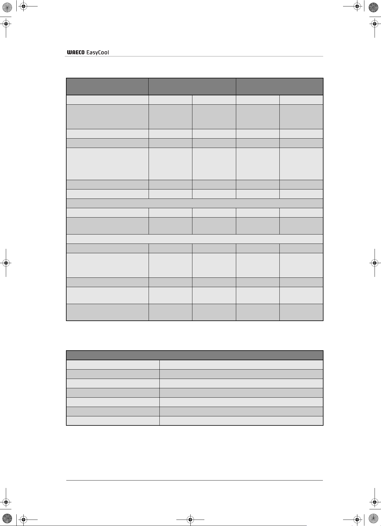
ec_1500_2000.book Seite 63 Freitag, 12. Mai 2006 4:11 16
12 Technical data
Technical data
easy cool devices Stationary air conditioning
Item number
EC-1500-AC EC-2000-AC EC-1500-AC/DC EC-2000-AC/DC
Cooling capacity
(in accordance with
1500 W 1800 W 1500 W 1800 W
ISO 5151)
Heating capacity
Number of blower levels
800 W 1200 W 800 W 1200 W
2 2 2 2
Dimensions
(L x W x H in mm)
Installation dimension from
1070 x 620 x 250 1070 x 620 x 250 1070 x 620 x 250 1070 x 620 x 250
the top edge of the roof
Refrigerant
Weight
R407C R407C R407C R407C
38.5 kg 38.5 kg 38.5 kg 38.5 kg
230 V AC operation
Input voltage
Power consumption in
cooling mode
230 V/50 Hz 230 V/50 Hz 230 V/50 Hz 230 V/50 Hz
<4A <5A <4A <5A
12 V DC operation
Input voltage
– – 12V (11V-15V) 12V (11V-15V)
Average power
consumption in
– – 75 A 90 A
cooling mode
Priority circuit, 230 V
Recommended dynamo
output
Recommended total battery
cap.
– – Available Available
– –
– –
Stationary and
mobile air conditioning
≥90 A ≥120 A
≥100 A ≥200 Ah
Only for stationary and mobile air conditioning:
ECW-012VS inverter for EC-1500/2000 AC/ DC
Output voltage
Constant output
Peak output
Efficiency
Low voltage shutdown
Dimensions (L x W x H in mm)
Weight
230 V
1600 W
3200 W
Up to 90 %
10.5 V
410 x 210 x 77
6kg
63
Page 64

ec_1500_2000.book Seite 64 Freitag, 12. Mai 2006 4:11 16
Technical data
Tests and certificates applied to the Roof air conditioner:
Tested according to:
EN 55014-1:2000+A1:2001
EN 55014-2:1997+A1:2001
EN 61000-3-2:2000
EN 61000-3-3:1995+A1:2001
EN 60335-1:1994+A1+A2+A11-A16
EN 60335-2-40:1997+A1
Versions, technical modifications and delivery options reserved.
64
Page 65

ec_1500_2000.book Seite 65 Freitag, 12. Mai 2006 4:11 16
Table des matières
1 Consignes de sécurité . . . . . . . . . . . . . . . . . . . . . . . . . . . . . . . . . . . . . . . . . . . . . . . 66
1.1 Précautions d’usage . . . . . . . . . . . . . . . . . . . . . . . . . . . . . . . . . . . . . . . . . . . . 66
2 Conventions du manuel . . . . . . . . . . . . . . . . . . . . . . . . . . . . . . . . . . . . . . . . . . . . . . 67
2.1 Informations générales à propos du manuel . . . . . . . . . . . . . . . . . . . . . . . . . . 67
2.2 Groupe-cible . . . . . . . . . . . . . . . . . . . . . . . . . . . . . . . . . . . . . . . . . . . . . . . . . . 67
2.3 Symboles et formats . . . . . . . . . . . . . . . . . . . . . . . . . . . . . . . . . . . . . . . . . . . .68
3 Usage conforme . . . . . . . . . . . . . . . . . . . . . . . . . . . . . . . . . . . . . . . . . . . . . . . . . . . . 69
4 Description technique . . . . . . . . . . . . . . . . . . . . . . . . . . . . . . . . . . . . . . . . . . . . . . . 69
4.1 Gamme d’appareils . . . . . . . . . . . . . . . . . . . . . . . . . . . . . . . . . . . . . . . . . . . . . 69
4.2 Pièces fournies . . . . . . . . . . . . . . . . . . . . . . . . . . . . . . . . . . . . . . . . . . . . . . . . 70
4.3 Fonctionnement . . . . . . . . . . . . . . . . . . . . . . . . . . . . . . . . . . . . . . . . . . . . . . . 71
4.4 Plaquettes de spécifications . . . . . . . . . . . . . . . . . . . . . . . . . . . . . . . . . . . . . . 72
4.5 Liste des pièces . . . . . . . . . . . . . . . . . . . . . . . . . . . . . . . . . . . . . . . . . . . . . . . 73
4.6 Schéma des connexions . . . . . . . . . . . . . . . . . . . . . . . . . . . . . . . . . . . . . . . . . 74
5 Installation. . . . . . . . . . . . . . . . . . . . . . . . . . . . . . . . . . . . . . . . . . . . . . . . . . . . . . . . . 75
5.1 Consignes de sécurité concernant l’installation . . . . . . . . . . . . . . . . . . . . . . . 75
5.2 Procédure d’installation . . . . . . . . . . . . . . . . . . . . . . . . . . . . . . . . . . . . . . . . . . 77
6 Utilisation. . . . . . . . . . . . . . . . . . . . . . . . . . . . . . . . . . . . . . . . . . . . . . . . . . . . . . . . . . 81
6.1 Contrôle avant la mise en service . . . . . . . . . . . . . . . . . . . . . . . . . . . . . . . . . . 82
6.2 Réglage des buses de ventilation . . . . . . . . . . . . . . . . . . . . . . . . . . . . . . . . . . 82
6.3 Mise en marche du climatiseur . . . . . . . . . . . . . . . . . . . . . . . . . . . . . . . . . . . . 82
6.4 Commutation sur Mode rafraîchissement . . . . . . . . . . . . . . . . . . . . . . . . . . . . 82
6.5 Commutation sur Mode chauffage . . . . . . . . . . . . . . . . . . . . . . . . . . . . . . . . . 82
6.6 Modification de la puissance frigorifique / calorifique . . . . . . . . . . . . . . . . . . . 83
6.7 Sélection de la vitesse de ventilation . . . . . . . . . . . . . . . . . . . . . . . . . . . . . . . 83
7 Entretien et nettoyage . . . . . . . . . . . . . . . . . . . . . . . . . . . . . . . . . . . . . . . . . . . . . . . 84
8 Retraitement . . . . . . . . . . . . . . . . . . . . . . . . . . . . . . . . . . . . . . . . . . . . . . . . . . . . . . . 84
8.1 Elimination du matériel d’emballage . . . . . . . . . . . . . . . . . . . . . . . . . . . . . . . . 84
8.2 Elimination de l’appareil usagé . . . . . . . . . . . . . . . . . . . . . . . . . . . . . . . . . . . . 84
9 Guide de dépannage. . . . . . . . . . . . . . . . . . . . . . . . . . . . . . . . . . . . . . . . . . . . . . . . . 85
10 Onduleur . . . . . . . . . . . . . . . . . . . . . . . . . . . . . . . . . . . . . . . . . . . . . . . . . . . . . . . . . . 86
10.1 Consignes générales de sécurité et d’installation . . . . . . . . . . . . . . . . . . . . . . 86
10.2 Usage conforme . . . . . . . . . . . . . . . . . . . . . . . . . . . . . . . . . . . . . . . . . . . . . . . 87
10.3 Fonctionnement . . . . . . . . . . . . . . . . . . . . . . . . . . . . . . . . . . . . . . . . . . . . . . . 87
10.4 Installation de l’onduleur . . . . . . . . . . . . . . . . . . . . . . . . . . . . . . . . . . . . . . . . . 87
10.5 Test de fonctionnement de l’onduleur ECW-012VS . . . . . . . . . . . . . . . . . . . . 89
10.6 Indicateur de dérangement . . . . . . . . . . . . . . . . . . . . . . . . . . . . . . . . . . . . . . . 90
11 Répartiteur de courant de charge . . . . . . . . . . . . . . . . . . . . . . . . . . . . . . . . . . . . . . 90
11.1 Usage prévu . . . . . . . . . . . . . . . . . . . . . . . . . . . . . . . . . . . . . . . . . . . . . . . . . . 90
11.2 Fonctionnement . . . . . . . . . . . . . . . . . . . . . . . . . . . . . . . . . . . . . . . . . . . . . . . 90
12 Caractéristiques techniques . . . . . . . . . . . . . . . . . . . . . . . . . . . . . . . . . . . . . . . . . . 91
65
Page 66

ec_1500_2000.book Seite 66 Freitag, 12. Mai 2006 4:11 16
Consignes de sécurité
1 Consignes de sécurité
Il est indispensable de lire attentivement ce manuel dans son intégralité.
Seul un respect minutieux des instructions peut garantir le parfait
fonctionnement et la fiabilité du climatiseur et prévenir les risques
d’accident matériel ou de -personne.
WAECO International décline toute responsabilité en cas de dommages
causés par :
des erreurs de montage,
des influences mécaniques et surtensions,
des modifications apportées à l’appareil sans autorisation explicite de la
part de WAECO International,
des usages différents de ceux décrits dans le manuel d’utilisation.
1.1 Précautions d’usage
N’utilisez le climatiseur de toit que pour l’usage prévu par le fabricant et
n’effectuez aucune modification ou transformation de l’appareil !
Ne faites fonctionner le climatiseur de toit que si le boîtier et les
raccordements sont intacts !
Débranchez tous les raccordements à l’alimentation électrique lors des
travaux sur l’appareil !
Le climatiseur de toit doit être installé de manière à ce qu’il ne puisse ni
se renverser ni tomber !
Protégez l’installation des salissures et de la poussière !
Ne passez pas sous un tunnel de lavage avec le climatiseur de toit !
Seule une entreprise qualifiée, parfaitement familiarisée avec les
dangers et règlements spécifiques à ces manipulations, est autorisée
à effectuer l’installation, l’entretien et les réparations éventuelles !
Veillez à ce qu’aucun objet inflammable ne soit entreposé ou monté
dans la zone d’évacuation de l’air. Une distance de 50 cm minimum
doit être respectée !
66
N’utilisez pas le climatiseur de toit à proximité de liquides inflammables
ou dans des pièces fermées.
Ne glissez pas les doigts dans les grilles ou les buses de ventilation et
n’introduisez aucun objet à l’intérieur de l’installation.
En cas d’incendie, n’ouvrez pas le capot supérieur du climatiseur de
toit mais utilisez un agent d’extinction agréé. N’utilisez pas d’eau pour
éteindre le feu.
Page 67

ec_1500_2000.book Seite 67 Freitag, 12. Mai 2006 4:11 16
1.1.1 Précautions concernant les lignes électriques
Si des lignes électriques doivent traverser des cloisons à arêtes vives,
utilisez des tubes vides ou des conduits pour câbles !
Ne faites pas passer de lignes électriques non fixées ou pliées à angle
vif sur des matériaux conducteurs (métal) !
Ne tirez pas sur les câbles !
Posez et fixez les lignes de manière à prévenir l’endommagement des
câbles et à empêcher que quelqu’un puisse trébucher dessus.
Utilisez uniquement des prises de courant mises à la terre protégées
par un disjoncteur.
Seule une entreprise qualifiée (répondant, par exemple, aux prescriptions
VDE 0100, Partie 721 en Allemagne) est autorisée à effectuer le
raccordement électrique.
Conventions du manuel
Protégez le raccordement secteur dans le véhicule avec au moins
10 ampères.
2 Conventions du manuel
2.1 Informations générales à propos du manuel
Ce manuel contient les informations et instructions essentielles pour
l’installation et l’utilisation correctes du climatiseur de toit. Les informations
qu’il contient s’adressent tout autant à l’entreprise réalisant l’installation
qu’à l’utilisateur du climatiseur.
Les remarques suivantes vous aideront à faire un usage correct de ce
manuel :
Le manuel, qui fait partie des éléments fournis, doit être soigneusement
conservé.
L’utilisation conforme décrite dans ce manuel garantit un fonctionnement
économique et fiable sur le long terme de l’appareil.
Les instructions d’installation vous donnent les informations nécessaires
pour le montage et servent également de base de référence si des
réparations s’avèrent nécessaires.
Le fabricant (WAECO) décline de toute responsabilité en cas de non
respect de ces instructions de montage et d’utilisation. Toute forme de
réclamation est en ce cas exclue.
2.2 Groupe-cible
Les informations concernant l’installation (voir chapitre « Installation »,
page 75) contenues dans ce manuel s’adressent au personnel qualifié,
travaillant dans des ateliers, informé des directives et des consignes de
sécurité à appliquer.
Les informations concernant l’appareil (instructions d’utilisation,
précautions d’usage, consignes de sécurité, etc.) s’adressent à
l’utilisateur du climatiseur de toit.
67
Page 68

ec_1500_2000.book Seite 68 Freitag, 12. Mai 2006 4:11 16
Conventions du manuel
2.3 Symboles et formats
Vous trouverez dans ce manuel différents symboles et formats. Voici leur
signification :
Format Signification Exemple
Gras Dans le texte, informations
importantes dont le sens doit
être bien compris
➤
✓ Résultat d’une manipulation ✓ Le système est maintenant
Texte décrivant une manipulation
Placez l’interrupteur (3) sur
FROID.
➤ Débrancher le raccordement
au pôle (+) de la batterie
d’alimentation.
prêt à fonctionner.
Remarque concernant :
un risque de blessure pour l’installateur ou l’utilisateur
et
un risque d’endommagement des appareils.
Indique une situation potentiellement dangereuse pendant le montage ou
l’utilisation du produit, pouvant entraîner l’endommagement de l’appareil
ou une pollution pour l’environnement ou des dommages materiels.
Informations particulières concernant l’utilisation du produit.
68
Page 69

ec_1500_2000.book Seite 69 Freitag, 12. Mai 2006 4:11 16
3 Usage conforme
Les climatiseurs de toit sont conçus pour chauffer avec de l’air chaud ou
rafraîchir avec de l’air froid l’intérieur de véhicules.
Les climatiseurs de toit ne sont pas adaptés pour une installation sur des
engins de chantier, des machines agricoles ou d’autres engins de travail.
Le fonctionnement correct n’est pas garanti en cas de vibrations trop fortes.
Les climatiseurs de toit sont conçus pour un fonctionnement à une
température extérieure inférieure à 43 °C en mode rafraîchissement ou
à une température de la pièce inférieure à 30 °C en mode chauffage.
Usage conforme
Les climatiseurs de toit EC-1500-AC, EC-2000-AC, EC-1500-AC/DC et
EC-2000-AC/DC de WAECO ont été développés pour une installation sur
le toit de véhicules (voir ill. 1, page 3).
Uniquement pour les versions AC/DC : N’utilisez jamais le mode chauffage
ou le mode automatique pendant la climatisation en route (12 V CC).
Vous pourriez ainsi endommager l’onduleur utilisé qui n’est pas conçu
pour cette fonction.
4 Description technique
La mise en service du climatiseur avec des valeurs absolues de tension qui
s’écartent des valeurs données conduit à l’endommagement de l’appareil.
Par conséquent, veuillez vous conformer aux instructions suivantes :
Vérifiez la tension (en particulier lors de l’utilisation sur des terrains de
camping, etc.) avant la mise en service du climatiseur.
4.1 Gamme d’appareils
Selon les modèles, les climatiseurs de toit sont adaptés pour la climatisation
à l’arrêt (EC-1500-AC et EC-2000-AC) ou pour la climatisation à l’arrêt et en
route (EC-1500-AC/DC et EC-2000-AC/DC). Vous trouverez les spécifications
exacte de votre appareil dans le chapitre « Caractéristiques techniques »,
page 91.
69
Page 70

ec_1500_2000.book Seite 70 Freitag, 12. Mai 2006 4:11 16
Description technique
Uniquement pour les versions AC/DC : Si les deux modes d’alimentation –
batterie du véhicule (12 V) et secteur (230 V/50 Hz) – sont à disposition du
climatiseur, la priorité est automatiquement donnée à l’alimentation 230 V.
4.2 Pièces fournies
EC-1500-AC
Définition pièce Numéro d’article
Climatiseur de toit EC-1500-AC EC-1500-AC
Câble secteur Schuko 4441300041
Cadre de fixation 4442500090
Cadre de recouvrement 4443000049
Joint 4443300010
Matériel de montage
Instructions d’utilisation climatiseur de toit 4445100104
EC-2000-AC
Définition pièce Numéro d’article
Climatiseur de toit EC-2000-AC EC-2000-AC
Câble secteur Schuko 4441300041
Cadre de fixation 4442500090
Cadre de recouvrement 4443000049
Joint 4443300010
Matériel de montage
Instructions d’utilisation climatiseur de toit 4445100104
EC-1500-AC/DC
Définition pièce Numéro d’article
Climatiseur de toit EC-1500-AC/DC EC-1500-AC/DC
Câble secteur Schuko 4441300041
Cadre de fixation 4442500090
Cadre-margeur 4443000049
Joint 4443300010
Onduleur ECW-012VS
Répartiteur de courant de charge ECL-75
Matériel de montage
Instructions d’utilisation climatiseur de toit 4445100104
Instructions d’utilisation répartiteur de courant de charge 4445100087
70
Page 71

ec_1500_2000.book Seite 71 Freitag, 12. Mai 2006 4:11 16
EC-2000-AC/DC
Définition pièce Numéro d’article
Climatiseur de toit EC-2000-AC/DC EC-2000-AC/DC
Câble secteur Schuko 4441300041
Cadre de fixation 4442500090
Cadre de recouvrement 4443000049
Joint 4443300010
Onduleur ECW-012VS
Répartiteur de courant de charge ECL-100
Matériel de montage
Instructions d’utilisation climatiseur de toit 4445100104
Instructions d’utilisation répartiteur de courant de charge 4445100087
4.3 Fonctionnement
Description technique
Les climatiseurs de toit permettent une climatisation variable de l’intérieur
d’un véhicule.
L’installation est capable de rafraîchir ou de réchauffer jusqu’à une valeur
donnée la température à l’intérieur d’un véhicule. La température à
atteindre lors du rafraîchissement dépend du type de véhicule, de la
température ambiante et de la puissance frigorifique de votre climatiseur.
Concernant la puissance frigorifique de votre climatiseur, voir chapitre
« Caractéristiques techniques », page 91.
Le cycle frigorifique du climatiseur est constitué de quatre éléments
principaux :
Compresseur
Le compresseur aspire le fluide frigorigène R407c utilisé et en réduit le
volume. La pression et, par suite, la température du frigorigène sont
ainsi augmentées.
Condenseur
Le condenseur intégré fonctionne comme un refroidisseur ou un
échangeur de chaleur. L’air circulant à proximité absorbe la chaleur,
le frigorigène gazeux se condense en se refroidissant. Le frigorigène
devient liquide.
Evaporateur
L’évaporateur refroidit et déshydrate l’air circulant à proximité.
Le frigorigène absorbe la chaleur. L’air rafraîchi est diffusé à
l’intérieur du véhicule par une unité de ventilation.
En cas de basse température, il est possible de réchauffer l’air ventilé.
L’air aspiré est alors réchauffé par des résistances électriques.
Un thermostat assure la régulation de la température ambiante.
71
Page 72

ec_1500_2000.book Seite 72 Freitag, 12. Mai 2006 4:11 16
Description technique
4.4 Plaquettes de spécifications
Les climatiseurs EC-1500-AC, EC-2000-AC, EC-1500-AC/DC et
EC-2000-AC/DC de WAECO sont munis de plaquettes de spécifications.
Elles informent l’installateur et l’utilisateur sur les spécifications de l’appareil.
(1) (2)
Groupe de produits/Range : Easy Cool
N° d’article/Art-No. : EC-1500-AC
Version/version : XXX
N° de série/Series-No. : XXX
Volume :
Tension d’alimentation/
Operation Voltage
Puissance nominale/
Power-Rating : 900 W chaud
Puissance nominale/
Power-Rating : 900 W froid
Frigorigène/Refrigerant : R 407c / 400 g
Pression max./
Max. Pressure : BP 11 bar / HP 30 bar
Classe climatique/
Climatic class : N
WAECO – Made in Germany
:
: CA 230 V ~ / 50 Hz
Groupe de produits/Range : Easy Cool
N° d’article/Art-No. : EC-1500-AC/DC
Version/version : XXX
N° de série/Series-No. : XXX
Volume :
Tension d’alimentation/
Operation Voltage
Puissance nominale/
Power-Rating : 900 W chaud
Puissance nominale/
Power-Rating : 900 W froid
Frigorigène/Refrigerant : R 407c / 400 g
Pression max./
Max. Pressure : BP 11 bar / HP 30 bar
Classe climatique/
Climatic class : N
WAECO – Made in Germany
:
: CA 230 V ~ / 50 Hz
(3) (4)
Groupe de produits/Range : Easy Cool
N° d’article/Art-No. : EC-2000-AC
Version/version : XXX
N° de série/Series-No. : XXX
Volume :
Tension d’alimentation/
Operation Voltage
Puissance nominale/
Power-Rating : 1300 W chaud
Puissance nominale/
Power-Rating : 1200 W froid
Frigorigène/Refrigerant : R 407c / 400 g
Pression max./
Max. Pressure : BP 11 bar / HP 30 bar
Classe climatique/
Climatic class : N
WAECO – Made in Germany
:
: CA 230 V ~ / 50 Hz
Groupe de produits/Range : Easy Cool
N° d’article/Art-No. : EC-2000-AC/DC
Version/version : XXX
N° de série/Series-No. : XXX
Volume :
Tension d’alimentation/
Operation Voltage
Puissance nominale/
Power-Rating : 1300 W chaud
Puissance nominale/
Power-Rating : 1200 W froid
Frigorigène/Refrigerant : R 407c / 400 g
Pression max./
Max. Pressure : BP 11 bar / HP 30 bar
Classe climatique/
Climatic class : N
WAECO – Made in Germany
:
: CA 230 V ~ / 50 Hz
72
Page 73

ec_1500_2000.book Seite 73 Freitag, 12. Mai 2006 4:11 16
4.5 Liste des pièces
– voir ill. 12, page 7 –
nº Quantité Désignation
1 1 Partie supérieure boîtier EC
2 1 Boîtier aération EC
3 1 Conduits d’aération EC
4 1 Élément chauffant
5 1 Décharge de traction importante (câble électronique 230 V)
6 1 Décharge de traction moindre (câble du détecteur)
7 1 Commande platine EC
8 1 Condensateur de marche
9 1 Condensateur de démarrage
10 1 Traversée de câble EC 4443200023/partie 1
11 1 Collier de fixation condensateur de marche EC
12 1 Collier de fixation condensateur de démarrage EC
13 1 Relais de démarrage EC
14
15 8 Pièce de réduction EC
16 2 Tuyau de connexion EC (long, 45 cm mesuré étendu)
17 2 Tuyau de connexion EC (court, 25 cm mesuré étendu)
18 1 Joint toit de cabine EC
19 1 Cadre de fixation EC
20 1 Cadre de recouvrement EC
21 1 Unité de commande EC
22 1 Filtre d’aération EC, grossier
23
24 1 Commutateur principal EC
25 1 Commutateur d’aération EC
26 4 Tuyères de sortie d’air EC
27 1 Bouton thermostat EC
28 1 Grille d’aspiration d’air EC
29 1 Thermostat EC
30 1 Panneau de caoutchouc cellulaire toit de cabine EC
31 1 Partie inférieure boîtier EC
32 1 Ventilateur de condensateur EC
33 1 Buse d’admission d’air EC
34 1 Unité frigorifique
35
36 1 Transfo 2 x 12 V 225 Watt EC
37 2 Joint condensateur
38 1 Support de fusible, métal (fusible thermique)
1 Écoulement d’eau, condensateur droite EC 4443200023/
1 Commutateur, chauffage-refroidissement EC
1 Écoulement d’eau, condensateur gauche EC 4443200023/
Description technique
Partie 3
(avec mise en pression chauffage-refroidissement)
Partie 2
73
Page 74

ec_1500_2000.book Seite 74 Freitag, 12. Mai 2006 4:11 16
Description technique
nº Quantité Désignation
39 1 Support, élément chauffant EC
40 1 Commutateur de température et fusible thermique EC
41 1 Joint condensateur (partie supérieure du boîtier)
4.6 Schéma des connexions
– voir ill. 13, page 8 –
nº Désignation
1 Transformateur
2 Transformateur sec.
3 Compresseur
4 Trafo 230 V
5 Commutateur E/A
6 230 V
7 ECC-1500
8 Inverseur E/A
9 Ventilateur évaporateur
10 Ventilateur condensateur
11 Commutateur
12 Commutateur chauffage
13 Compresseur
14 Ventilateur évaporateur
15 EC-2000 seulement : Thermostat point fixe
16 Fusible thermique
17 Ventilateur 1/2 (N)
18 Ventilateur condensateur
19 Thermostat (R)
20 Chaud/froid (S)
21 Marche/Arrêt (O)
22 Chauffage
23 Limitation de température
74
Couleurs des fils :
Désignation
dans ill.13
bl bleu
rt rouge
ge jaune
br marron
gn vert
sw noir
Couleur
Page 75

ec_1500_2000.book Seite 75 Freitag, 12. Mai 2006 4:11 16
5Installation
Seule une entreprise spécialisée possédant le savoir-faire nécessaire est
habilitée à effectuer l’installation du climatiseur. Les informations suivantes
sont destinées à un personnel qualifié, informé des directives et des
consignes de sécurité à appliquer.
5.1 Consignes de sécurité concernant l’installation
Les instructions de montage doivent être lues dans leur intégralité avant
l’installation du climatiseur.
Lors de l’installation du climatiseur, les consignes et conseils suivants
doivent être respectés :
Installation
Coupez toutes les alimentations électriques pendant les travaux sur le
climatiseur.
Uniquement pour EC-1500-AC/DC et EC-2000-AC/DC :
Veillez à ce que l’onduleur soit éteint et l’alimentation électrique coupée.
D’une manière générale, il faut contrôler avant l’installation si des
éléments du véhicule (par exemple : éclairages, armoires, portes, etc.)
ne risquent pas d’être endommagés par le montage du climatiseur.
Avant le montage, vous devez vérifier – par l’intermédiaire du constructeur
du véhicule – que la structure est conçue pour le poids statique du
climatiseur et les contraintes qu’il crée dans le véhicule en mouvement.
Le fabricant du climatiseur (WAECO) décline toute responsabilité.
Le constructeur du véhicule a éventuellement déjà prévu des
emplacements où l’ouverture pour l’installation du climatiseur peut
être percée sans risque d’affaiblissement de la structure, ni de
rupture de câbles électriques.
Choisissez comme emplacement de montage une zone plane,
suffisamment lisse, au milieu du toit du véhicule.
Veillez à ce qu’aucun objet inflammable ne soit entreposé ou monté
dans la zone d’évacuation de l’air. Une distance de 50 cm minimum doit
être respectée !
Assurez-vous qu’à l’intérieur du véhicule aucun obstacle ne puisse
gêner la fixation de l’unité de ventilation ou la sortie de l’air chaud ou
froid des buses de ventilation orientables.
Pour des raisons de sécurité, faites attention lors de l’installation du
climatiseur (opérations de perçage, de vissage, etc.) à la position des
faisceaux de câbles, conduites et autres éléments, éventuellement
encastrés et invisibles, qui se trouvent dans la zone de montage !
75
Page 76

ec_1500_2000.book Seite 76 Freitag, 12. Mai 2006 4:11 16
Installation
Une installation non conforme du climatiseur peut endommager l’appareil
de manière irréversible et mettre en danger la sécurité de l’utilisateur.
Si le climatiseur n’est pas installé conformément aux instructions de
montage décrites dans ce manuel, WAECO décline toute responsabilité
pour les pannes, pour les problèmes de sécurité liés au climatiseur et en
particulier pour les accidents matériels ou de personne.
Avant l’installation du climatiseur, il faut débrancher les raccordements
électriques suivants du véhicule :
Pôle positif de la batterie
Alimentation secteur
(l’alimentation de l’onduleur également pour les versions AC/DC).
Le non respect de ces consignes entraîne un danger d’électrocution.
Vous avez le choix entre deux possibilités pour le montage du climatiseur :
Percement d’une nouvelle ouverture (voir chapitre « Percement d’une
nouvelle ouverture », page 77). Il faut dans ce cas monter un cadre
adapté pour renforcer l’ouverture pratiquée.
Utilisation d’une ouverture de toit (lanterneau) déjà montée sur le
véhicule (voir chapitre « Installation dans une ouverture déjà présente »,
page 77).
Le montage du climatiseur doit être effectué par une entreprise spécialisée
possédant le savoir-faire nécessaire. Tous les points précédents, en
particulier ceux concernant les contraintes statiques, doivent être vérifiés
auprès du constructeur du véhicule.
Veuillez vous informer auprès du fabricant de votre véhicule si vous devez
modifier l’indication de la hauteur du véhicule dans les papiers du véhicule,
lorsque vous installez le climatiseur de toit.
76
Page 77

ec_1500_2000.book Seite 77 Freitag, 12. Mai 2006 4:11 16
5.2 Procédure d’installation
Avant de monter sur le toit du véhicule, assurez-vous que celui-ci est
praticable pour les personnes. Le constructeur du véhicule pourra vous
renseigner sur les charges de toit autorisées.
5.2.1 Percement d’une nouvelle ouverture
– voir ill. 4, page 4 et voir ill. 5, page 4 –
Percer les angles avant le sciage !
Afin de renforcer l’ouverture, utilisez un cadre de renfort en bois.
Installation
Il est impératif de porter des lunettes et des gants de protection lors de
l’utilisation d’outils ou de scies à main électriques.
➤ Choisissez une zone entre deux profils longitudinaux au milieu du toit.
➤ Marquez au feutre une ouverture carrée de 400 mm de côté.
➤ Découpez soigneusement l’ouverture sur le toit avec une scie
sauteuse ou un autre outil. Veillez à ne pas endommager de câbles
électriques pendant cette opération.
➤ Percez sur un côté une ouverture pour le passage du cable
d’alimentation électrique.
5.2.2 Installation dans une ouverture déjà présente
– voir ill. 1, page 3 –
L’installation du climatiseur de toit est possible pour les lanterneaux
mesurant de 400 mm à 435 mm de côté. Dans le cas d’un lanterneau
mesurant plus de 435 mm de côté, il est possible de réduire l’ouverture
en construisant soi-même un cadre. Dans ce cas, le lanterneau ne doit
cependant pas excéder 450 mm de côté.
La garantie de WAECO International s’applique uniquement aux éléments
fournis à la livraison. La garantie s’annule si le climatiseur est monté avec
des éléments étrangers au produit.
77
Page 78

ec_1500_2000.book Seite 78 Freitag, 12. Mai 2006 4:11 16
Installation
Lors du montage du climatiseur, vérifiez en permanence la stabilité
statique du véhicule et l’étanchéité des ouvertures percées pendant les
travaux.
Demonter le lanterneau
– voir ill. 2, page 3 et voir ill. 3, page 3 –
➤ Retirez toutes les vis et fixations du lanterneau présent.
➤ Retirez le lanterneau.
➤ Nettoyez les restes de mastic tout autour de l’ouverture avec un racloir
ou un outil similaire.
➤ Bouchez les trous de manière étanche avec du mastic.
Eliminez séparément tous les déchets, colle, silicone et joints.
Respectez les directives concernant le retraitement des déchets.
5.2.3 Réglage de l’unité de ventilation
– voir ill. 6, page 4 –
Afin de procéder à un montage précis du climatiseur de toit, vous devez
adapter la profondeur de l’unité de ventilation (voir ill. 7, page 5, Pos. A) à
l’épaisseur du toit de votre véhicule. L’unité de ventilation (voir ill. 6, page 4,
pos. A) est réglée en usine pour le montage sur toit d’une épaisseur d’env.
38 mm à 42 mm. Pour les toits plus épais ou plus fins, vous devez adapter
l’unité de ventilation au cadre de fixation (voir ill. 6, page 4, pos. B) de
l’installation :
➤ Retirez les 6 vis de fixation (voir ill. 6, page 4).
➤ Réglez la profondeur requise de l’unité de ventilation.
78
Lors du réglage de l’unité de ventilation, vérifiez que le climatiseur de toit
puisse encore se déplacer d’env. 8 à 10 mm vers le bas.
➤ Pour fixer l’unité de ventilation, veuillez avoir recours aux trous de
perçage prévus à cet effet.
Page 79

ec_1500_2000.book Seite 79 Freitag, 12. Mai 2006 4:11 16
5.2.4 Pose du câble d’alimentation
– voir ill. 8, page 5 –
Avant les travaux sur les éléments fonctionnant à l’électricité, assurez-vous
qu’ils ne sont pas sous tension !
➤ Reliez le climatiseur de toit à un circuit électrique en mesure de fournir
le courant nécessaire.
5.2.5 Pose des lignes pilotes
(Uniquement pour EC-1500-AC/DC et EC-2000-AC/DC)
Installation
Les climatiseurs EC-1500-AC/DC et EC-2000-AC/DC sont livrés avec un
onduleur (voir chapitre « Onduleur », page 86) et un répartiteur de courant
de charge (voir chapitre « Répartiteur de courant de charge », page 90).
Ces composants sont reliés au climatiseur par des lignes pilotes.
Uniquement pour les versions AC/DC : Pour l’installation du répartiteur
voir chapitre « Répartiteur de courant de charge », page 90.
Pour l’installation de l’onduleur ECW-012VS, voir chapitre « Onduleur »,
page 86.
➤ Posez les lignes pilotes à deux conducteurs fixées au climatiseur
jusqu’à l’emplacement de montage du répartiteur de courant de charge.
5.2.6 Montage du climatiseur
Il est nécessaire de s’assurer d’un centrage parfait du climatiseur.
Avant la mise en place, appliquez sur le joint un mastic butyle souple
(Sika Lastomer-710, par exemple). Après la mise en place, le joint doit
faire le tour complet en contact avec le toit du véhicule. C’est le seul
moyen de garantir une étanchéité totale !
➤ Montez le climatiseur sur le toit du véhicule.
Tenez compte du sens de la marche (flèche, voir ill. 1, page 3).
Tenez compte des contraintes statiques exercées sur le toit du véhicule.
Le toit du véhicule doit pouvoir supporter le poids du climatiseur. Même à
long terme, le toit du véhicule ne doit pas s’enfoncer ou se déformer sous
le poids du climatiseur.
79
Page 80

ec_1500_2000.book Seite 80 Freitag, 12. Mai 2006 4:11 16
Installation
Si sa force portante est insuffisante, le toit du véhicule peut être renforcé
(avec un cadre en bois, par exemple).
➤ Positionnez le climatiseur sur l’ouverture de montage.
5.2.7 Fixation du climatiseur
– voir ill. 7, page 5 –
➤ Montez le cadre de fixation (voir ill. 7, page 5, pos. B) à l’aide des vis
fournies (vis six pans 4xM8x100) et des rondelles U (4xM8).
Les vis six pans fournies (4xM8x100 mm) peuvent être utilisées pour une
épaisseur de toit jusqu’à 70 mm. Pour une épaisseur de toit supérieure,
il faut utiliser des vis six pans (Classe de qualité 8.8) d’une longueur
adaptée correspondante.
Appliquez un produit de fixation sur les vis de fixation !
Respectez le couple de serrage indiqué !
➤ Serrez les vis avec une clé dynamométrique au couple de serrage de
(3 Nm) 0,3 kgm.
➤ Fixez le cadre de recouvrement (voir ill. 7, page 5, pos. C) à l’aide des
4 vis à tête fraisée (Ø 4,8 x 25).
Uniquement pour les versions AC/DC : Terminez l’installation avec le
montage de l’onduleur (voir chapitre « Onduleur », page 86) et du
répartiteur de courant de charge (instructions de montage et de service
fournies).
80
Page 81

ec_1500_2000.book Seite 81 Freitag, 12. Mai 2006 4:11 16
6 Utilisation
Uniquement pour les versions AC/DC : Ne passez jamais directement de la
fonction de commande climatisation en route à la fonction de climatisation à
l’arrêt. Lors du passage d’une de ces fonctions de commande à l’autre,
éteignez l’installation et attendez au moins 5 minutes avant de remettre
l’appareil en marche.
Uniquement pour les versions AC/DC : N’utilisez jamais le mode
chauffage pendant la climatisation en route (12 V DC) car vous pourriez
ainsi endommager l’onduleur qui n’est pas conçu pour cette fonction.
Utilisation
Uniquement pour les versions AC/DC : Les bruits de fonctionnement du
climatiseur sont plus forts en route qu’à l’arrêt. L’augmentation du bruit
provient du fonctionnement de l’onduleur.
Pour garantir un fonctionnement optimal de votre climatiseur de toit EASY
COOL de WAECO, veuillez respecter les consignes d’utilisation suivantes :
En mode rafraîchissement ou en mode chauffage, évitez d’ouvrir
inutilement portes ou fenêtres.
Choisissez une température et une vitesse de ventilation appropriées.
Orientez correctement les buses de ventilation.
En mode rafraîchissement, après avoir éteint le climatiseur avec le
commutateur ON/OFF, attendez au moins 3 minutes avant de remettre
en marche l’installation.
Veillez à ce que les buses de ventilation et la grille d’aspiration ne
soient pas recouvertes par du tissu, du papier ou un quelconque objet.
Ne fermez pas complètement les buses de ventilation.
Le fabricant décline toute responsabilité en cas de non respect de ces
intructions d’utilisation. Il décline notamment toute responsabilité pour
tous les dommages secondaires, en particulier pour les dommages
secondaires qui pourraient être provoqués par une panne du climatiseur.
L’unité de ventilation du climatiseur est munie d’un panneau de commande
(voir ill. 9, page 5). Le panneau de commande sert à la commande des
fonctions.
81
Page 82

ec_1500_2000.book Seite 82 Freitag, 12. Mai 2006 4:11 16
Utilisation
6.1 Contrôle avant la mise en service
Avant de mettre en marche le climatiseur EASY COOL de WAECO,
veuillez respecter les consignes suivantes :
Contrôlez que la tension et la fréquence d’alimentation correspondent
bien aux valeurs indiquées précédemment.
Assurez-vous que ni l’ouverture d’aspiration, ni les buses de ventilation
ne sont bouchées. Aucune des grilles de ventilation ne doit être
bouchée afin de garantir un rendement optimal du climatiseur.
Ne glissez ni les doigts, ni un quelconque objet dans les buses de
ventilation ou la grille d’aspiration.
6.2 Réglage des buses de ventilation
– voir ill. 9, page 5 –
EC-2000 seulement :
Ne fermez jamais toutes les buses du climatiseur en même temps.
Le climatiseur givrerait de l’intérieur.
La quantité d’air introduite dans le véhicule peut être régulée en ouvrant
ou en tournant les buses de ventilation (voir ill. 9, page 5, pos. E).
➤ Ouvrez ou fermez les buses pour réguler la ventilation à l’endroit de
votre choix.
➤ Réglez l’angle de sortie du flux d’air en tournant les buses de ventilation.
6.3 Mise en marche du climatiseur
➤ Placez le commutateur ON/OFF (voir ill. 9, page 5, pos. C) sur la
position I pour mettre l’installation en marche.
✓ La climatisation est activée.
6.4 Commutation sur Mode rafraîchissement
➤ Placez le commutateur destiné au mode de fonctionnement (voir ill. 9,
page 5, pos. B) sur la position Refroidissement .
6.5 Commutation sur Mode chauffage
➤ Placez le commutateur destiné au mode de fonctionnement (voir ill. 9,
page 5, pos. B) sur la position Chauffage .
82
Page 83

ec_1500_2000.book Seite 83 Freitag, 12. Mai 2006 4:11 16
6.6 Modification de la puissance frigorifique / calorifique
Vous pouvez régler le chauffage ou le refroidissement du climatiseur de
toit à volonté par le thermostat (voir ill. 9, page 5, pos. D).
Mode rafraîchissement :
➤ Tournez le thermostat dans le sens inverse des aiguilles d’une montre
(marquage bleu) pour obtenir la puissance frigorifique de votre choix.
Mode chauffage :
➤ Tournez le thermostat dans le sens des aiguilles d’une montre
(marquage rouge) pour obtenir la puissance frigorifique de votre choix.
6.7 Sélection de la vitesse de ventilation
Le ventilateur intégré dans le climatiseur module l’intensité de l’apport
d’air. Le ventilateur peut être réglé manuellement :
Utilisation
➤ Positionnez le commutateur destiné au réglage de la ventilation
(voir ill. 9, page 5, pos. A) sur :
1 pour ventilation faible
2 pour ventilation haute
EC-1500 seulement :
Ne faites jamais fonctionner l’installation plusieurs heures par une
température d’air extérieure inférieure à 21 °C si les réglages suivants
ont été sélectionnés :
Ventilation 1
Mode rafraîchissement
Thermostat réglé sur refroidissement max.
Dans ces conditions, l’installation risque de givrer. Afin de prévenir cet
incident, réglez le thermostat sur la position centrale.
Les réglages suivants sont recommandés pour la vitesse de ventilation
(en mode de fonctionnement Refroidissement) :
Niveau I - refroidissement minimal (pendant la nuit)
Niveau II - refroidissement maximal
83
Page 84

ec_1500_2000.book Seite 84 Freitag, 12. Mai 2006 4:11 16
Entretien et nettoyage
7 Entretien et nettoyage
Veuillez respecter les consignes suivantes pour l’entretien et le nettoyage
de votre climatiseur de toit.
N’utilisez aucun objet coupant ou dur pour le nettoyage. Cela pourrait
endommager l’appareil.
Nettoyez de temps à autre le boîtier du climatiseur et de l’unité de
ventilation avec un chiffon humide.
Enlevez de temps à autre la poussière et autres salissures présentes
sur les lamelles de ventilation du climatiseur. Veillez ce faisant à ne pas
endommager les lamelles.
Vérifiez une fois par an que le joint du climatiseur sur le toit du véhicule
ne présente ni fissure ni autres détériorations.
Vérifiez de temps à autre que les écoulements d’eau de condensation
sur les côtés du climatiseur ne sont pas bouchés et que l’eau de
condensation peut s’écouler.
8 Retraitement
8.1 Elimination du matériel d’emballage
Ne jetez pas le matériel d’emballage à la poubelle. Veuillez respecter les
consignes suivantes :
jetez le carton d’emballage dans le container pour vieux papiers.
jetez le matériel d’emballage plastique dans le container adéquat.
Renseignez-vous auprès de votre commune sur le centre de recyclage
compétent.
8.2 Elimination de l’appareil usagé
84
Si votre appareil est définitivement hors-service, remettez-le au centre de
recyclage le plus proche ou à votre fournisseur qui le reprendra contre une
contribution modique.
Page 85
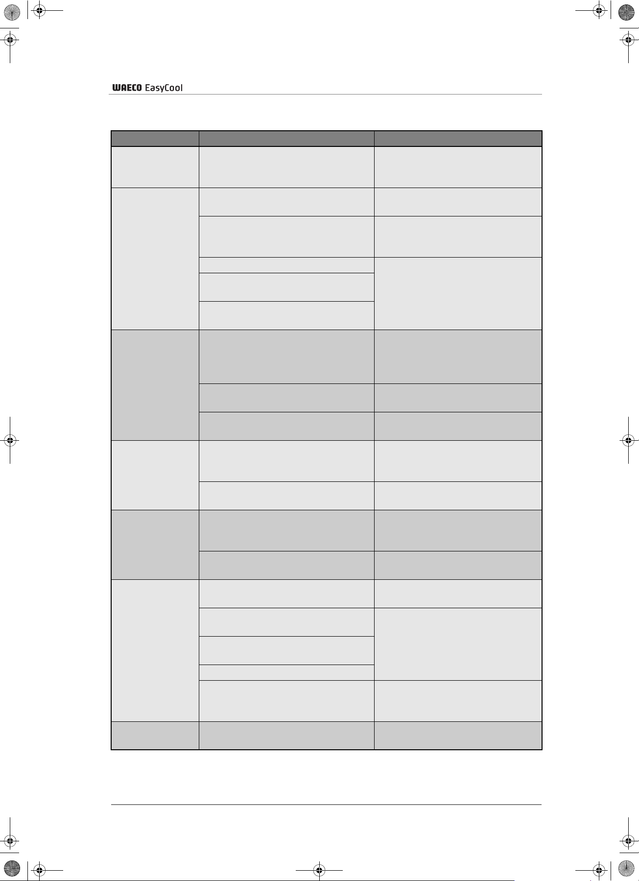
ec_1500_2000.book Seite 85 Freitag, 12. Mai 2006 4:11 16
9 Guide de dépannage
Anomalie Cause probable Remède
Le climatiseur
s’éteint en
permanence
Pas de
rafraîchissement
Pas de
chauffage
Mauvaise
ventilation
Infiltration d’eau
dans le véhicule
Le climatiseur
ne se met pas
en marche
Le climatiseur
ne s’éteint pas
Le détecteur de givrage interrompt
le fonctionnement.
Le climatiseur n’est pas en mode
rafraîchissement.
La température ambiante est
supérieure à 43 °C.
Le thermostat est défectueux. Prenez contact avec un atelier
La turbine de l’évaporateur est
défectueuse.
Le ventilateur du condensateur est
défectueux.
La température ambiante est
supérieure à 30 °C.
Le climatiseur n’est pas en mode
chauffage.
Le thermostat est défectueux. Prenez contact avec un atelier
L’aspiration d’air est bouchée. Faites en sorte que l’apport d’air
La turbine de l’évaporateur est
défectueuse.
Les ouvertures d’écoulement d’eau
de condensation sont bouchées.
Les joints sont défectueux. Prenez contact avec un atelier
Il n’y a pas de tension
d’alimentation.
La tension est trop faible
(inférieure à 200 V).
Le convertisseur de tension est
défectueux.
Le thermostat est endommagé.
La protection par fusible de
l’alimentation électrique est
trop faible.
Le thermostat est défectueux. Prenez contact avec un atelier
Guide de dépannage
La température extérieure est trop
basse ou toutes les buses de
ventilation sont fermées.
Mettez le climatiseur en mode
rafraîchissement.
Le climatiseur est conçu pour une
température ambiante inférieure à
43 °C.
spécialisé.
N’utilisez la fonction chauffage
du climatiseur que lorsque la
température est inférieure à
25 °C.
Mettez le climatiseur en mode
chauffage.
spécialisé.
ne soit pas empêché aux unités
d’aspiration d’air.
Prenez contact avec un atelier
spécialisé.
Nettoyez les ouvertures
d’écoulement d’eau de
condensation.
spécialisé.
Contrôlez l’alimentation
électrique.
Prenez contact avec un atelier
spécialisé.
Vérifiez les fusibles de
l’alimentation électrique.
spécialisé.
85
Page 86

ec_1500_2000.book Seite 86 Freitag, 12. Mai 2006 4:11 16
Onduleur
10 Onduleur
L’onduleur ECW-012VS est fourni uniquement avec les appareils
EC-1500-AC/DC et EC-2000-AC/ DC.
10.1 Consignes générales de sécurité et d’installation
Pour éviter tout risque de :
chocs électriques
incendie
blessures
destruction de l’appareil
il est impératif de suivre les consignes de sécurité ci-après.
Attention ! Risque de court-circuit !
Lors de travaux sur le véhicule, le point de mise à la masse pour la
batterie d’alimentation doit toujours être déconnecté en premier, et
seulement après la connexion à la batterie de démarrage !
L’onduleur ne doit être utilisé que pour l’usage prévu par le fabricant !
Lors des travaux sur l’onduleur, l’appareil doit être éteint. Tous les
raccordements au secteur 230 V et à la batterie 12 V doivent être
débranchés.
L’onduleur ne doit être utilisé que quand l’appareil et toutes les lignes
électriques sont intactes.
L’installation doit être faite de manière à empêcher tout mouvement,
chute ou renversement de l’appareil, même pendant les trajets.
Fixez l’appareil et les câbles en conséquence.
L’appareil installé doit être hors de portée des enfants.
86
L’onduleur ne doit pas être utilisé dans un environnement humide ou
mouillé. Il faut également éviter un environnement explosif.
Assurez-vous que l’aération est suffisante. L’onduleur produit de la
chaleur qui doit pouvoir se dissiper librement.
Les câbles de raccordement 12 V sont conçus pour des courants de
forte intensité. Une modification des câbles est déconseillée ou doit être
confiée à un spécialiste.
Les réparations et l’entretien sont l’exclusivité d’un personnel qualifié
et parfaitement informé des dangers et règlements spécifiques à ces
manipulations.
Page 87

ec_1500_2000.book Seite 87 Freitag, 12. Mai 2006 4:11 16
10.2 Usage conforme
Cet onduleur doit uniquement être utilisé avec les climatiseurs
EC-1500-AC/DC und EC-2000-AC/ DC.
Toute autre installation est interdite et peut entraîner la destruction
de l’onduleur ou de l’appareil avec lequel il est branché.
Au moyen de l’onduleur ECW-012VS de WAECO, les climatiseurs
EC-1500-AC/DC et EC-2000-AC/DC peuvent fonctionner sur secteur
230 V alternatif ou sur une batterie de 12 V.
10.3 Fonctionnement
Onduleur
L’onduleur ECW-012VS consiste en 3 unités de fonctionnement :
Génération d’une tension alternative de 230 V à partir d’une
alimentation de batterie 12 V.
Basculage automatique entre une alimentation secteur 230 V et une
tension générée 230 V. L’alimentation secteur est prioritaire.
Chargement de la batterie d’alimentation 12 V à 3 A maximum en
présence d’une tension extérieure.
10.4 Installation de l’onduleur
Face avant ECW-012VS voir ill. 10, page 6 :
Seule une entreprise spécialisée possédant le savoir-faire nécessaire est
habilitée à effectuer l’installation de l’onduleur. Les informations suivantes
sont destinées à un personnel qualifié, informé des directives et des
consignes de sécurité à appliquer.
N° dans ill.10 Désignation
1 Branchement de l’alimentation 230 V
2 Sortie 230 V CA
3 Non occupé
4 Branchement de la ligne pilote du climatiseur
5 Diode électroluminescente rouge
6 Diode électroluminescente verte
87
Page 88

ec_1500_2000.book Seite 88 Freitag, 12. Mai 2006 4:11 16
Onduleur
Dos ECW-012VS voir ill. 11, page 6 :
N° dans ill.11 Désignation
1 Bornes de connexion négatives
2 Ventilateur
3 Bornes de connexion positives
Débranchez l’alimentation secteur 230 V du véhicule !
Les câbles de raccordement 12 V de l’onduleur ECW-012VS ne
permettent une installation qu’à proximité de la batterie d’alimentation.
Veillez à ce que l’air puisse circuler librement pour la ventilation de l’appareil.
Veillez de même à ce que les prises et l’interface de raccordement restent
accessibles. Tous les câbles doivent êtres posés de manière à ce qu’aucune
arête ou ouverture ne puisse les endommager.
➤ Fixez l’onduleur avec des vis sur une base stable à proximité de la
batterie d’alimentation.
10.4.1 Raccordement de l’onduleur ECW-012VS à la batterie
Notez que lorsque vous déconnectez la batterie, toutes les mémoires
volatiles des appareils qu’elle alimente perdent leurs données.
➤ Débranchez le câble de raccordement négatif (masse) de la batterie.
➤ Débranchez le câble de raccordement positif de la batterie.
➤ Raccordez avec les deux câbles rouges (fournis) les bornes de
connexion positives de l’onduleur (voir ill. 11, page 6, position 1) avec
la borne de connexion pôle positif du câble de la batterie (et non pas
avec le pôle de la batterie).
88
➤ Raccordez avec les deux câbles noirs (fournis) les bornes de connexion
négatives de l’onduleur (voir ill. 11, page 6, position 1) avec la borne
de connexion pôle négatif du câble de la batterie.
Ne raccordez pas encore les câbles avec les pôles de la batterie.
Page 89

ec_1500_2000.book Seite 89 Freitag, 12. Mai 2006 4:11 16
Sur la face avant de l’onduleur se trouve la prise d’alimentation secteur
(voir ill. 10, page 6, position 1).
➤ Branchez le câble de raccordement au climatiseur compris dans la
livraison sur l’onduleur.
➤ Branchez le câble de raccordement à la prise 230 V installée dans le
véhicule.
10.4.2 Branchement au climatiseur
Le climatiseur doit être muni d’un câble de raccordement secteur 230 V ainsi
que d’un câble à deux conducteurs relié au répartiteur de courant de charge.
Sur la face avant de l’onduleur se trouvent les prises correspondantes de
raccordement secteur (voir ill. 10, page 6, position 2).
Onduleur
Pour le raccordement du répartiteur de courant de charge, voir les
instruction d’utilisation ECL-75, ECL-100, fournies avec le climatiseur.
➤ Branchez les fiches des deux lignes dans les prises correspondantes
en veillant à ce qu’elles soient bien enfoncées.
10.5 Test de fonctionnement de l’onduleur ECW-012VS
Des étincelles peuvent se produire lors du raccordement des bornes
de connexion avec les pôles de la batterie, dues au chargement des
capacités électriques internes.
➤ Connectez tout d’abord le câble de raccordement négatif puis le câble
de raccordement positif aux pôles de batterie respectifs.
➤ Mettez le climatiseur en marche (voir chapitre « Utilisation », page 81).
L’onduleur est allumé et éteint avec le commutateur ON/OFF du climatiseur.
Cet onduleur est équipé d’un raccordement prioritaire 230 V. En présence
d’une source d’alimentation 230 V, la tension de l’onduleur est coupée au
niveau de la prise de sortie de l’onduleur et le climatiseur est ainsi relié à
l’alimentation secteur externe. En cas de panne de l’alimentation secteur,
le fonctionnement avec l’onduleur se remet en marche automatiquement.
89
Page 90
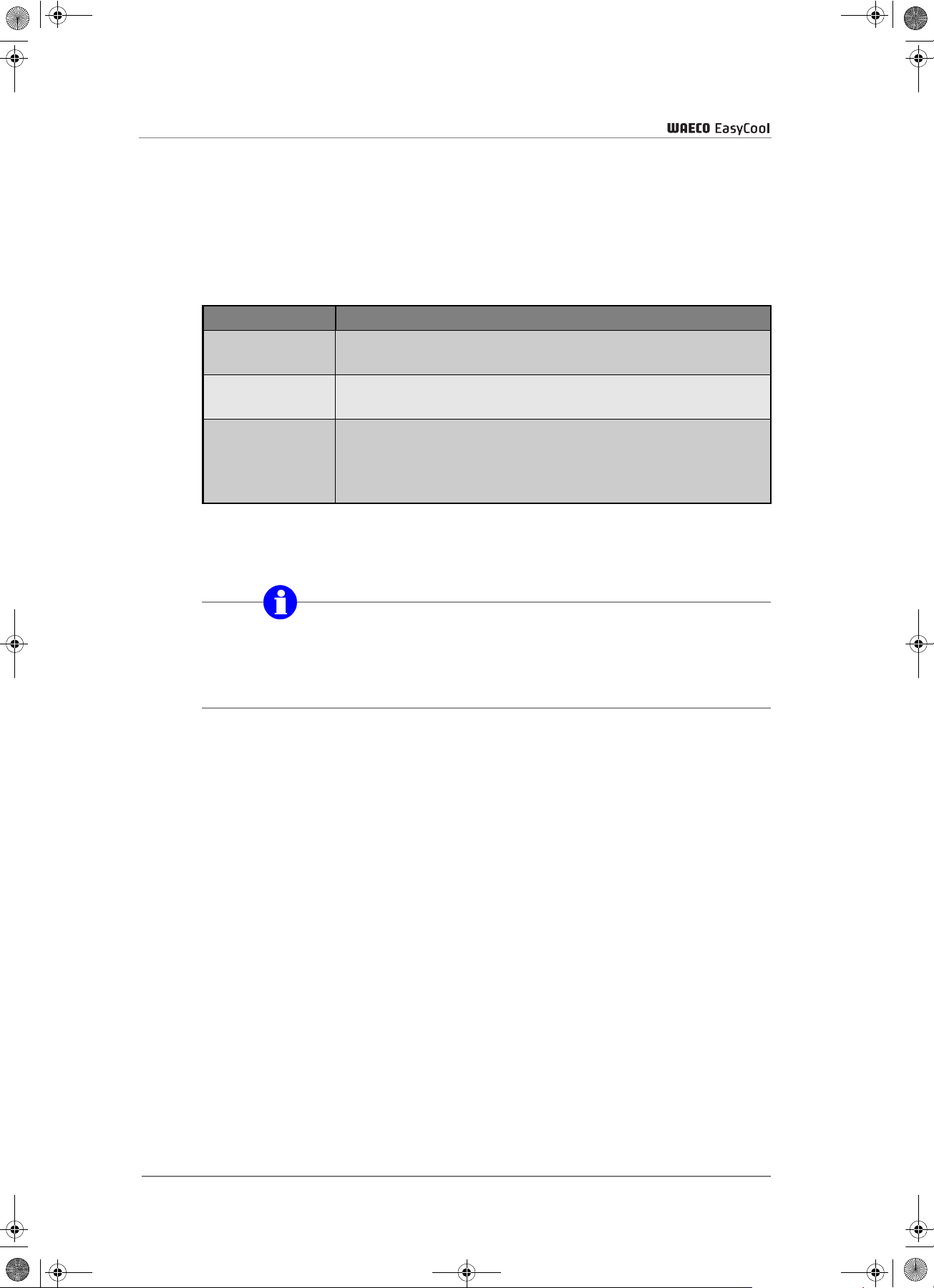
ec_1500_2000.book Seite 90 Freitag, 12. Mai 2006 4:11 16
Répartiteur de courant de charge
10.6 Indicateur de dérangement
Lorsque l’appareil se trouve en état de fonctionnement conforme, la diode
électroluminescente verte (voir ill. 10, page 6, position 6) est allumée.
En cas de dérangement, la diode verte s’éteint et la diode rouge (voir ill.
10, page 6, position 5) s’allume. Un dérangement peut être provoqué par
les causes suivantes :
Problème Signification
Sous-tension La capacité de la batterie à disposition est trop faible.
Surtension Vérifiez si la tension entrant dans l’onduleur correspond
Surchauffe L’onduleur a surchauffé. Vérifiez la ventilation.
Il faut recharger la batterie.
bien aux spécifications techniques de l’appareil.
Eventuellement, un fonctionnement continu dans
certaines conditions peut être trop intensif.
Débranchez l’appareil et laissez refroidir l’onduleur.
11 Répartiteur de courant de charge
Le répartiteur de courant de charge est fourni uniquement avec les
appareils EC-1500-AC/DC et EC-2000-AC/DC. Vous trouvez les
renseignements détaillés sur l’ECL-100 dans les intructions d’utilisation
fournies.
11.1 Usage prévu
Le répartiteur de courant de charge doit être utilisé en conjonction avec les
climatiseurs de toit EC-1500-AC/DC et EC-2000-AC/DC et l’onduleur
ECW-012VS. Cet appareil a été spécialement développé pour l’utilisation
des climatiseurs EC-1500-AC/DC et EC-2000-AC/DC en mode de
fonctionnement en route et à l’arrêt.
11.2 Fonctionnement
Le fonctionnement des climatiseurs EC-1500-AC/DC et EC-2000-AC/DC
en route requiert des courants de haute intensité qui sont prélevés sur le
circuit électrique du véhicule. Le répartiteur gère le courant à disposition
entre la batterie du véhicule, la batterie d’alimentation et le climatiseur en
fonction du chargement par l’alternateur.
90
Page 91

ec_1500_2000.book Seite 91 Freitag, 12. Mai 2006 4:11 16
12 Caractéristiques techniques
Caractéristiques techniques
Climatiseurs easy cool Climatisation à l’arrêt
N° d’article
Puissance frigorifique
(d’après ISO 5151)
Puissance calorifique
Vitesses de ventilation
EC-1500-AC EC-2000-AC EC-1500-AC/DC EC-2000-AC/DC
1500 W 1800 W 1500 W 1800 W
800 W 1200 W 800 W 1200 W
2 2 2 2
Dimensions (Lxlxh en mm)
Cotes de montage limite
1070x620x250 1070x620x250 1070x620x250 1070x620x250
supérieure toit
Frigorigène
Poids
R407C R407C R407C R407C
38,5 kg 38,5 kg 38,5 kg 38,5 kg
Fonctionnement 230 V AC
Tension d’entrée
Intensité absorbée en mode
rafraîchissement
230 V/50 Hz 230 V/50 Hz 230 V/50 Hz 230 V/50 Hz
<4A <5A <4A <5A
Fonctionnement 12 V DC
Tension d’entrée
– – 12V (11V-15V) 12V (11V-15V)
Intensité absorbée
moyenne en mode
– – 75 A 90 A
rafraîchissement
Raccordement prioritaire,
230 V
Puissance d’alternateur
conseillée
Capacité de batterie
conseillée
– – oui oui
– –
– –
Climatisation à l’arrêt et et
en route
≥90 A ≥120 A
≥100 A ≥200 A
Uniquement pour la climatisation à l’arrêt et en route :
Onduleur ECW-012VS pour EC-1500/2000 AC/DC
Tension de sortie
Puissance continue
Puissance de crête
Rendement
Arrêt sous-tension
Dimension (Lxlxh en mm)
Poids
230 V
1600 W
3200 W
jusqu’à 90 %
10,5 V
410x210x77
6kg
91
Page 92
ec_1500_2000.book Seite 92 Freitag, 12. Mai 2006 4:11 16
Caractéristiques techniques
Sur les climatiseur de toit contrôles/certificats en vigueur :
Contrôlé conformément à
EN 55014-1:2000+A1:2001
EN 55014-2:1997+A1:2001
EN 61000-3-2:2000
EN 61000-3-3:1995+A1:2001
EN 60335-1:1994+A1+A2+A11-A16
EN 60335-2-40:1997+A1
Spécifications sous réserve de modifications liées aux évolutions
techniques et aux disponibilités de livraison.
92
Page 93

ec_1500_2000.book Seite 93 Freitag, 12. Mai 2006 4:11 16
Índice
1 Indicaciones de seguridad. . . . . . . . . . . . . . . . . . . . . . . . . . . . . . . . . . . . . . . . . . . . 94
1.1 Manejo de la instalación . . . . . . . . . . . . . . . . . . . . . . . . . . . . . . . . . . . . . . . . . 94
2 Convenciones del manual de instrucciones . . . . . . . . . . . . . . . . . . . . . . . . . . . . . 95
2.1 Información general acerca del manual de instrucciones . . . . . . . . . . . . . . . . 95
2.2 Grupo de destinatarios . . . . . . . . . . . . . . . . . . . . . . . . . . . . . . . . . . . . . . . . . . 95
2.3 Símbolos y formatos . . . . . . . . . . . . . . . . . . . . . . . . . . . . . . . . . . . . . . . . . . . .96
3 Uso adecuado . . . . . . . . . . . . . . . . . . . . . . . . . . . . . . . . . . . . . . . . . . . . . . . . . . . . . . 97
4 Descripción técnica . . . . . . . . . . . . . . . . . . . . . . . . . . . . . . . . . . . . . . . . . . . . . . . . . 97
4.1 Variaciones del aparato . . . . . . . . . . . . . . . . . . . . . . . . . . . . . . . . . . . . . . . . . 97
4.2 Volumen de entrega . . . . . . . . . . . . . . . . . . . . . . . . . . . . . . . . . . . . . . . . . . . . 98
4.3 Funcionamiento . . . . . . . . . . . . . . . . . . . . . . . . . . . . . . . . . . . . . . . . . . . . . . . 99
4.4 Placas de identificación . . . . . . . . . . . . . . . . . . . . . . . . . . . . . . . . . . . . . . . . 100
4.5 Lista de piezas . . . . . . . . . . . . . . . . . . . . . . . . . . . . . . . . . . . . . . . . . . . . . . . 101
4.6 Esquema de conexiones . . . . . . . . . . . . . . . . . . . . . . . . . . . . . . . . . . . . . . . . 102
5 Instalación . . . . . . . . . . . . . . . . . . . . . . . . . . . . . . . . . . . . . . . . . . . . . . . . . . . . . . . . 103
5.1 Indicaciones para la instalación . . . . . . . . . . . . . . . . . . . . . . . . . . . . . . . . . . 103
5.2 Pasos de instalación . . . . . . . . . . . . . . . . . . . . . . . . . . . . . . . . . . . . . . . . . . . 105
6 Manejo . . . . . . . . . . . . . . . . . . . . . . . . . . . . . . . . . . . . . . . . . . . . . . . . . . . . . . . . . . . 109
6.1 Control antes de la puesta en funcionamiento . . . . . . . . . . . . . . . . . . . . . . . 110
6.2 Ajuste de las toberas de aire . . . . . . . . . . . . . . . . . . . . . . . . . . . . . . . . . . . . 110
6.3 Conexión del equipo de aire acondicionado de techo . . . . . . . . . . . . . . . . . 110
6.4 Cambiar a modo enfriar . . . . . . . . . . . . . . . . . . . . . . . . . . . . . . . . . . . . . . . . 110
6.5 Cambiar a modo calefacción . . . . . . . . . . . . . . . . . . . . . . . . . . . . . . . . . . . . 110
6.6 Modificar la potencia frigorífica/calorífica . . . . . . . . . . . . . . . . . . . . . . . . . . . 111
6.7 Seleccionar los niveles de ventilación . . . . . . . . . . . . . . . . . . . . . . . . . . . . . 111
7 Mantenimiento y cuidado. . . . . . . . . . . . . . . . . . . . . . . . . . . . . . . . . . . . . . . . . . . . 112
8 Evacuación . . . . . . . . . . . . . . . . . . . . . . . . . . . . . . . . . . . . . . . . . . . . . . . . . . . . . . . 112
8.1 Eliminación del material de embalaje . . . . . . . . . . . . . . . . . . . . . . . . . . . . . . 112
8.2 Evacuación del aparato usado . . . . . . . . . . . . . . . . . . . . . . . . . . . . . . . . . . . 112
9 Eliminación de averías . . . . . . . . . . . . . . . . . . . . . . . . . . . . . . . . . . . . . . . . . . . . . . 113
10 Convertidor . . . . . . . . . . . . . . . . . . . . . . . . . . . . . . . . . . . . . . . . . . . . . . . . . . . . . . . 114
10.1 Indicaciones generales de seguridad y para el montaje . . . . . . . . . . . . . . . . 114
10.2 Uso adecuado . . . . . . . . . . . . . . . . . . . . . . . . . . . . . . . . . . . . . . . . . . . . . . . . 115
10.3 Funcionamiento . . . . . . . . . . . . . . . . . . . . . . . . . . . . . . . . . . . . . . . . . . . . . . 115
10.4 Instalación del convertidor . . . . . . . . . . . . . . . . . . . . . . . . . . . . . . . . . . . . . . 115
10.5 Prueba de funcionamiento del convertidor ECW-012VS . . . . . . . . . . . . . . . 117
10.6 Indicación de averías . . . . . . . . . . . . . . . . . . . . . . . . . . . . . . . . . . . . . . . . . . 118
11 Distribuidor de corriente de carga . . . . . . . . . . . . . . . . . . . . . . . . . . . . . . . . . . . . 118
11.1 Uso previsto . . . . . . . . . . . . . . . . . . . . . . . . . . . . . . . . . . . . . . . . . . . . . . . . . 118
11.2 Funcionamiento . . . . . . . . . . . . . . . . . . . . . . . . . . . . . . . . . . . . . . . . . . . . . . 118
12 Datos técnicos . . . . . . . . . . . . . . . . . . . . . . . . . . . . . . . . . . . . . . . . . . . . . . . . . . . . 119
93
Page 94

ec_1500_2000.book Seite 94 Freitag, 12. Mai 2006 4:11 16
Indicaciones de seguridad
1 Indicaciones de seguridad
Es absolutamente necesario leer detenidamente el contenido completo del
manual de instrucciones.
Únicamente a través del cumplimiento de las instrucciones se podrá
garantizar un funcionamiento correcto, la eficacia del equipo de aire
acondicionado de techo y la protección -frente a daños personales y
materiales.
WAECO International no se hace responsable de los daños causados
como consecuencia de:
errores de montaje,
daños en el sistema debido a influencias mecánicas o sobretensiones,
modificaciones realizadas en el aparato sin el consentimiento expreso
de WAECO International,
utilización del aparato para otros fines distintos a los descritos en las
instrucciones de montaje.
1.1 Manejo de la instalación
¡Utilice el equipo de aire acondicionado de techo únicamente para los
fines previstos por el fabricante y no realice modificaciones en el aparato!
¡Utilice el equipo de aire acondicionado de techo únicamente si la
carcasa y los cables no están dañados!
¡Al trabajar en el equipo, desconecte todas las conexiones a la
alimentación eléctrica!
¡Instale el equipo de aire acondicionado de techo de forma segura para
evitar que se pueda caer o volcar!
¡Proteja el equipo frente a suciedad y polvo!
¡No entre nunca con el equipo de aire acondicionado en una instalación
de lavado!
94
¡La instalación, el mantenimiento y la reparación sólo los puede llevar a
cabo personal técnico especializado que conozca los peligros
inherentes a dichas tareas y las normas pertinentes!
¡Asegúrese de que no haya objetos inflamables situados o montados en
la zona de salida de aire. La distancia debe ser como mínimo de 50 cm!
No utilice el equipo de aire acondicionado de techo cerca de fluidos
inflamables o en habitaciones cerradas.
No introduzca las manos en la rejilla ni en la tobera de ventilación ni
tampoco inserte objetos extraños en el equipo.
En caso de incendio, no abra la tapa superior del equipo de aire
acondicionado de techo y utilice medios de extinción autorizados.
No utilice agua para extinguir el fuego.
Page 95

ec_1500_2000.book Seite 95 Freitag, 12. Mai 2006 4:11 16
1.1.1 Manejo de los cables eléctricos
¡Si los cables se deben pasar a través de paredes con bordes afilados,
utilice tubos corrugados o guías de cable!
¡Los cables no deben quedar sueltos ni muy doblados al colocarlos en
materiales conductores de electricidad (metales)!
¡No tire de los cables!
Coloque y fije los cables de forma que no supongan ningún peligro de
tropiezo y que no resulten dañados.
Utilice siempre cajas de enchufe puestas a tierra y protegidas mediante
interruptor FS.
La conexión eléctrica sólo podrá ser llevada a cabo por personal
técnico especializado (p. ej. en Alemania VDE 0100, parte 721).
Convenciones del manual de instrucciones
Proteja por fusible la conexión a la red en el vehículo con un mínimo de
10 amperios.
2 Convenciones del manual de instrucciones
2.1 Información general acerca del manual de
instrucciones
Este manual contiene la información y las instrucciones fundamentales
para el uso adecuado y la instalación del equipo de aire acondicionado de
techo. La información contenida va dirigida tanto al usuario como a la
empresa instaladora de dicho equipo.
Las siguientes indicaciones le ayudarán a utilizar correctamente el manual
de instrucciones:
El manual de instrucciones es parte del volumen de entrega y debe
guardarse cuidadosamente.
El uso correcto descrito en este manual garantiza un funcionamiento
económico y prolonga la vida útil del aparato.
Las instrucciones de montaje le proporcionarán indicaciones importantes
para el montaje y, al mismo tiempo, sirve como manual de consulta a la
hora de realizar reparaciones.
El fabricante (WAECO) no se hace responsable de fallos debidos a la
no observancia de estas instrucciones de montaje y uso. En este caso,
queda excluido cualquier tipo de reclamación.
2.2 Grupo de destinatarios
La información referente a la instalación (véase el capítulo “Instalación”
en la página 103) incluida en este manual va dirigida a personal técnico
de talleres familiarizado con las directivas y medidas de seguridad que
se hayan de aplicar.
La información referente al aparato (indicaciones de funcionamiento,
manejo del aparato, indicaciones de seguridad, etc.) van dirigidas al
usuario del equipo de aire acondicionado de techo.
95
Page 96

ec_1500_2000.book Seite 96 Freitag, 12. Mai 2006 4:11 16
Convenciones del manual de instrucciones
2.3 Símbolos y formatos
En esta documentación encontrará determinados símbolos y formatos.
Estos símbolos y formatos tienen el siguiente significado:
Formato Significado Ejemplo
Negrita Información importante en el
texto que se debe comprender
con claridad
➤
✓ Resultado de un paso realizado ✓ El equipo está preparado para
Textos que indican pasos a
realizar
Sitúe el interruptor (3) sobre el
símbolo ENFRIAR.
➤ Retire la conexión de polo
positivo (+) de la batería de
abastecimiento.
funcionar.
Indicación referente a:
posibles riesgos de lesión para el instalador o el usuario
y
posible deterioro del aparato.
Muestra una posible situación de peligro que podría producirse durante el
montaje o el funcionamiento del producto y que podría ocasionar daños
en el aparato, un deterioro del medio ambiente o perjuicios económicos.
Información especial referente al manejo del producto.
96
Page 97

ec_1500_2000.book Seite 97 Freitag, 12. Mai 2006 4:11 16
3 Uso adecuado
Los equipos de aire acondicionado de techo están capacitados para
calentar o enfriar el espacio interior de los vehículos con aire caliente o
frío respectivamente.
Los equipos de aire acondicionado de techo no son apropiados para la
instalación en maquinaria de construcción, en maquinaria agrícola o en
maquinaria similar. En caso de vibraciones demasiado fuertes no se
garantiza un funcionamiento correcto.
Uso adecuado
Los equipos de aire acondicionado de techo están diseñados para
funcionar a una temperatura ambiente por debajo de 43 ºC en el modo
enfriar y por debajo de 30 ºC en el modo calefacción.
Los equipos de aire acondicionado de techo EC-1500-AC, EC-2000-AC,
EC-1500-AC/DC y EC-2000-AC/DC de WAECO están concebidos para la
instalación en techos de vehículos (véase fig. 1, en la página 3).
Sólo para modelos AC/DC: nunca utilice el modo calefacción ni el modo
automático del equipo durante la climatización con el vehículo en marcha
(12 V CC). El convertidor utilizado no está diseñado para esta función, por
lo que podría resultar dañado.
4 Descripción técnica
El funcionamiento del equipo de aire acondicionado de techo con niveles
de tensión que se desvíen de los valores señalados lleva al deterioro del
aparato.
Por esta razón, es importante tener en cuenta lo siguiente: antes de poner
en funcionamiento el equipo, deberá comprobar la tensión (sobre todo
antes de la puesta en funcionamiento en campings, etc.).
4.1 Variaciones del aparato
Dependiendo del modelo de equipo de aire acondicionado de techo, los
aparatos serán adecuados para la climatización con el vehículo parado
(EC-1500-AC/DC y EC-2000-AC) o también para climatización con el
vehículo parado y en marcha (EC-1500-AC/DC y EC-2000-AC/DC).
Las especificaciones exactas de su aparato podrá encontrarlas en el
capítulo “Datos técnicos” en la página 119.
97
Page 98

ec_1500_2000.book Seite 98 Freitag, 12. Mai 2006 4:11 16
Descripción técnica
Sólo para modelos AC/DC: si para la climatización con el vehículo parado
y con el vehículo en marcha, el equipo de aire acondicionado de techo
dispone de las dos fuentes de corriente - batería del vehículo (12 V) y red
fija (230 V/50 Hz) -, mediante una conexión de prioridad se seleccionará
siempre el suministro de corriente de 230 V.
4.2 Volumen de entrega
EC-1500-AC
Descripción de las piezas Número de artículo
Equipo de aire acondicionado de techo EC-1500-AC EC-1500-AC
Cable de red tipo Schuko 4441300041
Marco de sujeción 4442500090
Marco cobertor 4443000049
Junta 4443300010
Material de montaje
Instrucciones de uso para el equipo de aire
acondicionado de techo
4445100104
EC-2000-AC
Descripción de las piezas Número de artículo
Equipo de aire acondicionado de techo EC-2000-AC EC-2000-AC
Cable de red tipo Schuko 4441300041
Marco de sujeción 4442500090
Marco cobertor 4443000049
Junta 4443300010
Material de montaje
Instrucciones de uso para el equipo de aire
acondicionado de techo
4445100104
EC-1500-AC/DC
Descripción de las piezas Número de artículo
Equipo de aire acondicionado de techo EC-1500-AC/DC EC-1500-AC/DC
Cable de red tipo Schuko 4441300041
Marco de sujeción 4442500090
Marco cobertor 4443000049
Junta 4443300010
Convertidor ECW-012VS
Distribuidor de corriente de carga ECL-75
Material de montaje
Instrucciones de uso para el equipo de aire
acondicionado de techo
Instrucciones de uso para el distribuidor de corriente
de carga
4445100104
4445100087
98
Page 99
ec_1500_2000.book Seite 99 Freitag, 12. Mai 2006 4:11 16
EC-2000-AC/DC
Descripción de las piezas Número de artículo
Equipo de aire acondicionado de techo EC-2000-AC/DC EC-2000-AC/DC
Cable de red tipo Schuko 4441300041
Marco de sujeción 4442500090
Marco cobertor 4443000049
Junta 4443300010
Convertidor ECW-012VS
Distribuidor de corriente de carga ECL-100
Material de montaje
Instrucciones de uso para el equipo de aire
acondicionado de techo
Instrucciones de uso para el distribuidor de corriente
de carga
Descripción técnica
4445100104
4445100087
4.3 Funcionamiento
Con ayuda del equipo de aire acondicionado de techo se puede llevar a
cabo una climatización variable del habitáculo del vehículo.
El equipo está capacitado para disminuir o aumentar la temperatura hasta
un valor determinado en el habitáculo del vehículo. La temperatura que
se puede alcanzar al refrigerar depende del modelo de vehículo, de la
temperatura ambiente y de la potencia frigorífica de su equipo de aire
acondicionado. Con respecto a la potencia frigoríca de su equipo de aire
acondicionado véase el capítulo “Datos técnicos” en la página 119.
El circuito de refrigeración de los equipos de aire acondicionado está
formado por cuatro componentes principales:
Compresor
El compresor aspira el refrigerante R407 utilizado y lo condensa.
De este modo, se aumenta la presión y la temperatura del refrigerante.
Condensador
El condensador integrado funciona como un radiador o un
intercambiador de calor. El aire que circula absorbe calor, el gas
refrigerante caliente se enfría y se condensa. El refrigerante se licúa.
Evaporador
El evaporador enfría el aire que circula y lo deshumedece. El refrigerante
absorbe calor. El aire enfriado se distribuye en el habitáculo del vehículo
a través de una unidad de salida de aire.
A temperaturas bajas existe la posibilidad de calentar el aire que sale.
Para ello, el aire aspirado se calienta mediante una calefacción de
resistencia eléctrica. Un termostato se encarga de regular la temperatura
del aire.
99
Page 100

ec_1500_2000.book Seite 100 Freitag, 12. Mai 2006 4:11 16
Descripción técnica
4.4 Placas de identificación
En los equipos de aire acondicionado de techo EC-1500-AC, EC-2000-AC,
EC-1500-AC/DC, EC-2000-AC/DC de WAECO se encuentran instaladas
placas de identificación. Estas placas de identificación informan al usuario
y al instalador sobre las especificaciones del aparato.
(1) (2)
Gama de productos/Range : Easy Cool
Artículo nº/Art-No. : EC-1500-AC
Modelo/version : XXX
Nº de serie/Series-No. : XXX
Capacidad/Volume :
Tensión de conexión/
Operation Voltage
Potencia nominal/
Power-Rating : 900 W hot
Potencia nominal/
Power-Rating : 900 W cold
Refrigerante/Refrigerant : R 407c / 400 g
Presión máx./
Max. Pressure
Tipo de clima/
Climatic class : N
WAECO – Made in Germany
:
: CA 230 V ~ / 50 Hz
: ND 11 bares /
HD 30 bares
Gama de productos/Range : Easy Cool
Artículo nº/Art-No. : EC-1500-AC/DC
Modelo/version : XXX
Nº de serie/Series-No. : XXX
Capacidad/Volume :
Tensión de conexión/
Operation Voltage
Potencia nominal/
Power-Rating : 900 W hot
Potencia nominal/
Power-Rating : 900 W cold
Refrigerante/Refrigerant : R 407c / 400 g
Presión máx./
Max. Pressure
Tipo de clima/
Climatic class : N
WAECO – Made in Germany
:
: CA 230 V ~ / 50 Hz
: ND 11 bares /
HD 30 bares
(3) (4)
Gama de productos/Range : Easy Cool
Artículo nº/Art-No. : EC-2000-AC
Modelo/version : XXX
Nº de serie/Series-No. : XXX
Capacidad/Volume :
Tensión de conexión/
Operation Voltage
Potencia nominal/
Power-Rating : 1300 W hot
Potencia nominal/
Power-Rating : 1200 W cold
Refrigerante/Refrigerant : R 407c / 400 g
Presión máx./
Max. Pressure
Tipo de clima/
Climatic class : N
WAECO – Made in Germany
:
: CA 230 V ~ / 50 Hz
: ND 11 bares /
HD 30 bares
Gama de productos/Range : Easy Cool
Artículo nº/Art-No. : EC-2000-AC/DC
Modelo/version : XXX
Nº de serie/Series-No. : XXX
Capacidad/Volume :
Tensión de conexión/
Operation Voltage
Potencia nominal/
Power-Rating : 1300 W hot
Potencia nominal/
Power-Rating : 1200 W cold
Refrigerante/Refrigerant : R 407c / 400 g
Presión máx./
Max. Pressure
Tipo de clima/
Climatic class : N
WAECO – Made in Germany
:
: CA 230 V ~ / 50 Hz
: ND 11 bares /
HD 30 bares
100
 Loading...