

Wacker Neuson WM 90 Repair Manual

www.wackergroup.com
0160157en 002
0207
Engine
WM 90
REPAIR MANUAL
0160157EN


WM 90 Repair Foreword
Operating / Parts Information
You must be familiar with the operation of this machine before you
attempt to troubleshoot or repair it. Basic operating and maintenance
procedures are described in the Operator’s Manual supplied with the
machine. Keep a copy of the Operator’s Manual with the machine at all
times. Use the separate Parts Book supplied with the machine to order
replacement parts. If you are missing either of the documents, please
contact Wacker Corporation to order a replacement.
Damage caused by misuse or neglect of the unit should be brought to
the attention of the operator to prevent similar occurrences from
happening in the future.
This manual provides information and procedures to safely repair and
maintain the above Wacker model(s). For your own safety and
protection from injury, carefully read, understand, and observe all
instructions described in this manual. THE INFORMATION
CONTAINED IN THIS MANUAL IS BASED ON MACHINES
MANUFACTURED UP TO THE TIME OF PUBLICATION. WACKER
CORPORATION RESERVES THE RIGHT TO CHANGE ANY
PORTION OF THIS INFORMATION WITHOUT NOTICE.
wc_tx000387gb.fm 3

Foreword WM 90 Repair
CALIFORNIA
Proposition 65 Warning:
Engine exhaust, some of its constituents, and certain vehicle
components, contain or emit chemicals known to the State of
WARNING
California to cause cancer and birth defects or other reproductive
harm.
Laws Pertaining to Spark Arresters
Notice: State Health Safety Codes and Public Resources Codes
specify that in certain locations spark arresters be used on internal
combustion engines that use hydrocarbon fuels. A spark arrester is a
device designed to prevent accidental discharge of sparks or flames
from the engine exhaust. Spark arresters are qualified and rated by
the United States Forest Service for this purpose.
In order to comply with local laws regarding spark arresters, consult
the engine distributor or the local Health and Safety Administrator.
All rights, especially copying and distribution rights, are reserved.
Copyright 2007 by Wacker Corporation
No part of this publication may be reproduced in any form or by any
means, electronic or mechanical, including photocopying, without
express written permission from Wacker Corporation.
Any type of reproduction or distribution not authorized by Wacker
Corporation represents an infringement of valid copyrights, and
violators will be prosecuted. We expressly reserve the right to make
technical modifications, even without due notice, which aim at
improving our machines or their safety standards.
wc_tx000387gb.fm 4

WM 90 Repair Table of Contents
1. Emission Control System Information 8
2. Safety Information 13
2.1 Operating Safety ................................................................................ 14
2.2 Operator Safety while using Internal Combustion Engines ................ 15
2.3 Service Safety .................................................................................... 16
2.4 Label Locations .................................................................................. 17
2.5 Safety Labels ...................................................................................... 18
2.6 Operating Labels ................................................................................ 21
3. Technical Data 23
3.1 Specifications ..................................................................................... 23
3.2 Performance ....................................................................................... 24
4. Theory of Operation 25
4.1 Application .......................................................................................... 25
4.2 Recommended Fuel ........................................................................... 25
4.3 Before Starting ................................................................................... 25
4.4 To Start ............................................................................................... 26
4.5 To Stop ............................................................................................... 27
4.6 Component Descriptions .................................................................. 27
4.7 Cross Section Across Shaft ................................................................ 32
4.8 Cross Section Across Shaft Components .......................................... 33
4.9 Cross Section Along Shaft ................................................................. 34
4.10 Cross Section Along Shaft Components ............................................ 35
5. Maintenance 36
5.1 Periodic Maintenance Schedule ......................................................... 36
5.2 Servicing Air Cleaner .......................................................................... 37
5.3 Servicing Fuel Filter and Fuel Tank .................................................... 38
5.4 Long-Term Storage ............................................................................ 39
wc_br0160157en_002TOC.fm 5

Table of Contents WM 90 Repair
6. Dissassembly/Reassembly General Information 40
6.1 Tools ....................................................................................................40
6.2 Ordering Parts .....................................................................................40
6.3 Reference Numbers ( ) ........................................................................40
6.4 Weight Block .......................................................................................40
7. Disassembly Procedures 41
7.1 Removing Engine from Rammer .........................................................41
7.2 Draining Oil ..........................................................................................43
7.3 Removing Recoil Starter and Blower Housing ....................................44
7.4 Removing Muffler ................................................................................45
7.5 Removing Governor Lever, Carburetor, Speed Control Lever ............46
7.6 Removing Ignition Coil, Flywheel, and Spark Plug ..............................47
7.7 Removing Rocker Cover and Cylinder Head ......................................48
7.8 Removing Bearing Cover ....................................................................49
7.9 Removing Camshaft and Tappets .......................................................50
7.10 Removing Connecting Rod and Piston ...............................................51
7.11 Removing Crankshaft ..........................................................................52
7.12 Removing Intake and Exhaust Valves .................................................53
8. Reassembly Procedures 54
8.1 Notes on Reassembly .........................................................................54
8.2 Crankshaft ...........................................................................................54
8.3 Reassembling Piston ...........................................................................55
8.4 Reassembling Piston and Connecting Rod .........................................56
8.5 Installing Piston ...................................................................................57
8.6 Installing Tappets and Camshaft .........................................................58
8.7 Adjusting Crankshaft End Play ............................................................59
8.8 Installing Main Bearing Cover .............................................................60
8.9 Cylinder Head ......................................................................................61
8.10 Reassembling Rocker Arms and Push Rods ......................................62
8.11 Adjusting Valve Clearances ................................................................63
8.12 Installing Rocker Cover and Spark Plug ..............................................64
8.13 Installing Flywheel Magneto ................................................................65
8.14 Installing Ignition Coil ..........................................................................65
8.15 Installing Governor, Speed Control System, and Carburetor ..............66
wc_br0160157en_002TOC.fm 6

WM 90 Repair Table of Contents
8.16 Adjusting Governor System ................................................................ 67
8.17 Installing Muffler ................................................................................. 67
8.18 Installing Blower Housing and Recoil Starter ..................................... 68
8.19 Re-installing Engine ........................................................................... 69
8.20 Break-in Operation ............................................................................. 71
9. Sub Systems 72
9.1 Magneto ............................................................................................. 72
9.2 Engine Basic Electric Theory ............................................................. 72
9.3 Electrical Components ....................................................................... 73
9.4 Automatic Decompression System .................................................... 74
9.5 Diaphragm-Type Carburetor .............................................................. 75
9.6 Carburetor Disassembly Procedure ................................................... 78
9.7 Carburetor Inspection ......................................................................... 79
9.8 Carburetor Reassembly ..................................................................... 79
9.9 Carburetor Adjustments ..................................................................... 80
10. Recoil Starter 81
10.1 Recoil Starter Disassembly ................................................................ 81
10.2 Checking the Recoil Starter After Reassembly .................................. 85
10.3 Starter Assembly Exploded View ....................................................... 86
10.4 Disassembling the Starter .................................................................. 87
10.5 Inspecting the Starter ......................................................................... 87
10.6 Assembling the Starter ....................................................................... 88
10.7 Replacing the Starter Rope ................................................................ 89
11. Clearance Data and Limits Table 91
11.1 Term Descriptions .............................................................................. 91
12. Troubleshooting 99
12.1 Troubleshooting Introduction .............................................................. 99
12.2 Troubleshooting Procedures .............................................................. 99
wc_br0160157en_002TOC.fm 7

Emission Control System Information
1. Emission Control System Information
Source of Emissions
The combustion process produces carbon monoxide, oxides of
nitrogen, and hydrocarbons. Control of hydrocarbons and oxides of
nitrogen is very important because, under certain conditions, they
react to form photochemical smog when subjected to sunlight. Carbon
monoxide does not react in the same way, but it is toxic.
Wacker utilizes lean carburetor settings and other systems to reduce
the emissions of carbon monoxide, oxides of nitrogen, and
hydrocarbons.
The U.S. and California Clean Air Acts
EPA and California regulations require all manufacturers to furnish
written instructions describing the operation and maintenance of
emission control systems.
The following instructions and procedures must be followed in order to
keep the emissions from your Wacker engine within the emissions
standards.
Tampering and Altering
Tampering with or altering the emission control system may increase
emissions beyond the legal limit. Among those acts that constitute
tampering are:
•Removal or alteration of any part of the intake, fuel, or exhaust
systems.
•Altering or defeating the speed-adjusting mechanism to cause the
engine to operate outside its design parameters.
Problems That May Affect Emissions
If you are aware of any of the following symptoms, have your engine
inspected and repaired by your servicing dealer.
•Hard starting or stalling after starting.
•Rough idle.
•Misfiring or backfiring under load.
•Afterburning (backfiring).
•Black exhaust smoke or high fuel consumption.
8

Emission Control System Information
Replacement Parts
The emission control systems on your Wacker engine were designed,
built, and certified to conform with EPA and California emissions
regulations. We recommend the use of genuine Wacker parts
whenever you have maintenance done. These original-design
replacement parts are manufactured to the same standards as the
original parts, so you can be confident of their performance. The use
of replacement parts that are not of the original design and quality may
impair the effectiveness of your emission control system.
A manufacturer of an aftermarket part assumes the responsibility that
the part will not adversely affect emission performance. The
manufacturer or rebuilder of the part must certify that use of the part
will not result in a failure of the engine to comply with emission
regulations.
Maintenance
Follow the maintenance schedule. Remember that this schedule is
based on the assumption that your machine will be used for its
designed purpose. Sustained high-load or high-temperature operation,
or use in unusually wet or dusty conditions, will require more frequent
service.
OXYGENATED FUELS
Some conventional gasolines are being blended with alcohol or an
ether compound. These gasolines are collectively referred to as
oxygenated fuels. To meet clean air standards, some areas of the
United States and Canada use oxygenated fuels to help reduce
emissions.
If you use an oxygenated fuel, be sure it is unleaded and meets the
minimum octane rating requirement.
Before using an oxygenated fuel, try to confirm the fuel’s contents.
Some States / Provinces require this information to be posted on the
pump.
The following are EPA-approved percentages of oxygenates:
ETHANOL - (ethyl or grain alcohol) 10% by volume. You may use
gasoline containing up to 10% ethanol by volume. Gasoline containing
ethanol may be marketed under the name “Gasohol”.
MTBE - (methyl tertiary butyl ether) 15% by volume. You may use
gasoline containing up to 15% MTBE by volume.
9

Emission Control System Information
METHANOL - (methyl or wood alcohol) 5% by volume. You may use
gasoline containing up to 5% methanol by volume, as long as it
contains cosolvents and corrosion inhibitors to protect the fuel system.
Gasoline containing more than 5% methanol by volume may cause
starting and/or performance problems. It may also damage metal,
rubber, and plastic parts of your fuel system.
If you notice any undesirable operating symptoms, try another service
station, or switch to another brand of gasoline.
Fuel system damage or performance problems resulting from the use
of an oxygenated fuel containing more than the percentages of
oxygenates mentioned above are not covered under warranty.
EMISSIONS COMPONENT DEFECT WARRANTY COVERAGE
This emission warranty is applicable in all States.
Wacker Corporation, N92 W15000 Anthony Avenue, Menomonee
Falls, WI 53051-1504, (herein "Wacker") warrant(“s”) to the initial retail
purchaser and each subsequent owner, that this non-road engine
(herein "engine") has been designed, built, and equipped to conform
at the time of initial sale to all applicable regulations of the U.S.
Environmental Protection Agency (EPA), and that the engine is free of
defects in materials and workmanship which would cause this engine
to fail to conform with EPA regulations during its warranty period.
For the components listed under PARTS COVERED, the service
dealer authorized by Wacker will, at no cost to you, make the
necessary diagnosis, repair, or replacement necessary to ensure that
the engine complies with applicable U.S. EPA regulations.
EMISSISON COMPONENT DEFECT WARRANTY PERIOD
The warranty period for this engine begins on the date of sale to the
initial purchaser and continues for a period of 2 years.
PARTS COVERED
Listed below are the parts covered by the Emission Components
Defect Warranty. Some of the parts listed below may require
scheduled maintenance and are warranted up to the first scheduled
replacement point for that part.
(1) Fuel Metering System
(i) Carburetor and internal parts (and/or pressure regulator or fuel
injection system).
(ii) Air/fuel ratio feedback and control system, if applicable.
(iii) Cold start enrichment system, if applicable.
(iv) Regulator assembly (gaseous fuel, if applicable) .
(2) Air Induction System
10

Emission Control System Information
(i) Intake manifold, if applicable.
(ii) Air filter.
(3) Ignition System
(i) Spark plugs.
(ii) Magneto or electronic ignition system.
(iii) Spark advance/retard system, if applicable.
(4) Exhaust manifold, if applicable
(5) Miscellaneous Items Used in Above Systems
(i) Electronic controls, if applicable.
(ii) Hoses, belts, connectors, and assemblies.
(iii) Filter lock assembly (gaseous fuel, if applicable).
OBTAINING WARRANTY SERVICE
To obtain warranty service, take your engine to the nearest authorized
Wacker service dealer. Bring your sales receipts indicating date of
purchase for this engine. The service dealer authorized by Wacker will
perform the necessary repairs or adjustments within a reasonable
amount of time and furnish you with a copy of the repair order. All parts
and accessories replaced under this warranty become the property of
Wacker.
WHAT IS NOT COVERED
Conditions resulting from tampering, misuse, improper adjustment
(unless they were made by the service dealer authorized by Wacker
during a warranty repair), alteration, accident, failure to use the
recommended fuel and oil, or not performing required maintenance
services.
The replacement parts used for required maintenance services.
Consequential damages such as loss of time, inconvenience, loss of
use of the engine or equipment, etc.
Diagnosis and inspection charges that do not result in warranty-eligible
service being performed.
Any non-authorized replacement part, or malfunction of authorized
parts due to use of non-authorized parts.
OWNER'S WARRANTY RESPONSIBILITIES
As the engine owner, you are responsible for the performance of the
required maintenance listed in your owner's manual. Wacker
recommends that you retain all receipts covering maintenance on your
engine, but Wacker cannot deny warranty solely for the lack of receipts
or for your failure to ensure the performance of all scheduled
maintenance. As the engine owner, you should however be aware that
Wacker may deny warranty coverage if your engine or a part has failed
due to abuse, neglect, improper maintenance or unapproved
modifications.
11

Emission Control System Information
You are responsible for presenting your engine to the nearest service
dealer authorized by Wacker when a problem exists.
If you have any questions regarding your warranty rights and
responsibilities, you should contact the WACKER CORPORATION
Product Support Department (U.S.A. 1-800-770-0957, Canada 1-877977-0775) for the information.
THINGS YOU SHOULD KNOW ABOUT THE EMISSION CONTROL
SYSTEM WARRANTY:
MAINTENANCE AND REPAIRS
You are responsible for the proper maintenance of the engine. You
should keep all receipts and maintenance records covering the
performance of regular maintenance in the event questions arise.
These receipts and maintenance records should be transferred to
each subsequent owner of the engine. Wacker reserves the right to
deny warranty coverage if the engine has not been properly
maintained. Warranty claims will not be denied, however, solely
because of the lack of required maintenance or failure to keep
maintenance records.
MAINTENANCE, REPLACEMENT OR REPAIR OF EMISSION
CONTROL DEVICES AND SYSTEMS MAY BE PERFORMED BY
ANY REPAIR ESTABLISHMENT OR INDIVIDUAL; HOWEVER,
WARRANTY REPAIRS MUST BE PERFORMED BY A SERVICE
DEALER AUTHORIZED BY WACKER. THE USE OF PARTS THAT
ARE NOT EQUIVALENT IN PERFORMANCE AND DURABILITY TO
AUTHORIZED PARTS MAY IMPAIR THE EFFECTIVENESS OF THE
EMISSION CONTROL SYSTEM AND MAY HAVE A BEARING ON
THE OUTCOME OF A WARRANTY CLAIM.
If other than the parts authorized by Wacker are used for maintenance
replacements or for the repair of components affecting emission
control, you should assure yourself that such parts are warranted by
their manufacturer to be equivalent to the parts authorized by Wacker
in their performance and durability.
HOW TO MAKE A CLAIM
All repair qualifying under this limited warranty must be performed by
a service dealer authorized by Wacker. In the event that any emissionrelated part is found to be defective during the warranty period, you
shall notify WACKER CORPORATION Product Support Department
(U.S.A. 1-800-770-0957, Canada 1-877-977-0775) and you will be
advised of the appropriate warranty service dealer or service providers
where the warranty repair can be performed.
12
WM 90 Repair Safety Information
2. Safety Information
This manual contains DANGER, WARNING, CAUTION, NOTICE and
NOTE callouts which must be followed to reduce the possibility of
personal injury, damage to the equipment, or improper service.
This is the safety alert symbol. It is used to alert you to potential
personal injury hazards. Obey all safety messages that follow this
symbol to avoid possible injury or death.
DANGER indicates a hazardous situation which, if not avoided, will
result in death or serious injury.
DANGER
WARNING indicates a hazardous situation which, if not avoided, could
result in death or serious injury.
WARNING
CAUTION
CAUTION indicates a hazardous situation which, if not avoided, could
result in minor or moderate injury.
NOTICE: Used without the safety alert symbol, NOTICE indicates a
hazardous situation which, if not avoided, could result in property
damage.
Note: Contains additional information important to a procedure.
wc_si000143gb.fm 13

Safety Information WM 90 Repair
2.1 Operating Safety
Familiarity and proper training are required for the safe operation of
machine. Machines operated improperly or by untrained personnel
can be dangerous. Read the operating instructions contained in both
WARNING
2.1.1 NEVER operate this machine in applications for which it is not
2.1.2 NEVER allow anyone to operate this equipment without proper
2.1.3 NEVER touch the engine or muffler while the engine is on or
2.1.4 NEVER use accessories or attachments that are not recommended by
this manual and the engine manual and familiarize yourself with the
location and proper use of all controls. Inexperienced operators should
receive instruction from someone familiar with the machine before
being allowed to operate it.
intended.
training. People operating this equipment must be familiar with the
risks and hazards associated with it.
immediately after it has been turned off. These areas get hot and may
cause burns.
Wacker. Damage to equipment and injury to the user may result.
2.1.5 NEVER leave machine running unattended.
2.1.6 NEVER tamper with or disable the function of operating controls.
2.1.7 NEVER use choke to stop engine.
2.1.8 NEVER operate the machine in areas where explosions may occur.
2.1.9 ALWAYS read, understand, and follow procedures in the Operator’s
Manual before attempting to operate the equipment.
2.1.10 ALWAYS be sure that all other persons are at a safe distance from the
machine. Stop the machine if people step into the working area of the
machine.
2.1.11 ALWAYS be sure operator is familiar with proper safety precautions
and operation techniques before using machine.
2.1.12 ALWAYS wear protective clothing appropriate to the job site when
operating equipment.
2.1.13 ALWAYS wear hearing protection when operating equipment.
2.1.14 ALWAYS keep hands, feet, and loose clothing away from moving parts
of the machine.
2.1.15 ALWAYS use common sense and caution when operating the
machine.
2.1.16 ALWAYS be sure the rammer will not tip over, roll, slide, or fall when
not being operated.
2.1.17 ALWAYS turn the engine OFF when the rammer is not being operated.
wc_si000143gb.fm 14
WM 90 Repair Safety Information
2.1.18 ALWAYS guide the rammer in such a way that the operator is not
squeezed between the rammer and solid objects. Special care is
required when working on uneven ground or when compacting coarse
material. Make sure to stand firmly when operating the machine under
such conditions.
2.1.19 ALWAYS operate the rammer in such a way that there is no danger of
it turning over or falling in, when working near the edges of breaks, pits,
slopes, trenches and platforms.
2.1.20 ALWAYS store the equipment properly when it is not being used.
Equipment should be stored in a clean, dry location out of the reach of
children.
2.1.21 ALWAYS close fuel valve on engines equipped with one when
machine is not being operated.
2.1.22 ALWAYS operate machine with all safety devices and guards in place
and in working order. DO NOT modify or defeat safety devices. DO
NOT operate machine if any safety devices or guards are missing or
inoperative.
2.2 Operator Safety while using Internal Combustion Engines
Internal combustion engines present special hazards during operation
and fueling. Read and follow the warning instructions in the engine
owner’s manual and the safety guidelines below. Failure to follow the
DANGER
2.2.1 DO NOT smoke while operating the machine.
2.2.2 DO NOT smoke when refueling the engine.
2.2.3 DO NOT refuel a hot or running engine.
2.2.4 DO NOT refuel the engine near an open flame.
2.2.5 DO NOT spill fuel when refueling the engine.
2.2.6 DO NOT run the engine near open flames.
2.2.7 DO NOT run the machine indoors or in an enclosed area such as a
2.2.8 ALWAYS refill the fuel tank in a well-ventilated area.
warnings and safety guidelines could result in severe injury or death.
deep trench unless adequate ventilation, through such items as
exhaust fans or hoses, is provided. Exhaust gas from the engine
contains poisonous carbon monoxide gas; exposure to carbon
monoxide can cause loss of consciousness and may lead to death.
2.2.9 ALWAYS replace the fuel tank cap after refueling.
2.2.10 ALWAYS check the fuel lines and the fuel tank for leaks and cracks
before starting the engine. Do not run the machine if fuel leaks are
present or the fuel lines are loose.
wc_si000143gb.fm 15

Safety Information WM 90 Repair
2.3 Service Safety
Poorly maintained machines can become a safety hazard! In order for
the machine to operate safely and properly over a long period of time,
periodic maintenance and occasional repairs are necessary.
WARNING
2.3.1 DO NOT attempt to clean or service the machine while it is running.
Rotating parts can cause severe injury.
2.3.2 DO NOT operate the machine without an air cleaner.
2.3.3 DO NOT remove air cleaner cover, paper element, or precleaner while
engine is running.
2.3.4 DO NOT alter engine speeds. Run the engine only at speeds specified
in the Technical Data Section.
2.3.5 DO NOT crank a flooded engine with the spark plug removed on
gasoline-powered engines. Fuel trapped in the cylinder will squirt out
the spark plug opening.
2.3.6 DO NOT test for spark on gasoline-powered engines if the engine is
flooded or the smell of gasoline is present. A stray spark could ignite
the fumes.
2.3.7 DO NOT use gasoline or other types of fuels or flammable solvents to
clean parts, especially in enclosed areas. Fumes from fuels and
solvents can become explosive.
2.3.8 ALWAYS replace the safety devices and guards after repairs and
maintenance.
2.3.9 ALWAYS keep the area around the muffler free of debris such as
leaves, paper, cartons, etc. A hot muffler could ignite the debris and
start a fire.
2.3.10 ALWAYS do Periodic Maintenance as recommended in the Operator’s
Manual.
2.3.11 ALWAYS clean debris from engine cooling fins.
2.3.12 ALWAYS replace worn or damaged components with spare parts
designed and recommended by Wacker Corporation.
2.3.13 ALWAYS disconnect the spark plug on machines equipped with
gasoline engines, before servicing, to avoid accidental start-up.
2.3.14 ALWAYS keep the machine clean and labels legible. Replace all
missing and hard-to-read labels. Labels provide important operating
instructions and warn of dangers and hazards.
wc_si000143gb.fm 16
WM 90 Repair Safety Information
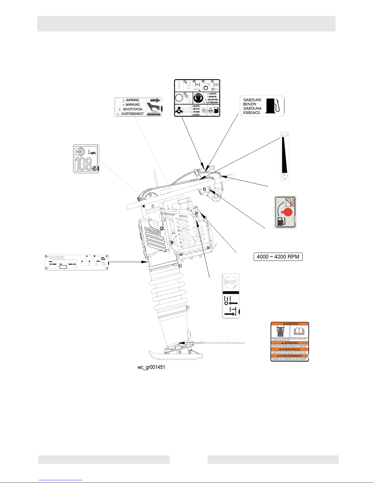
2.4 Label Locations
wc_si000143gb.fm 17
Safety Information WM 90 Repair
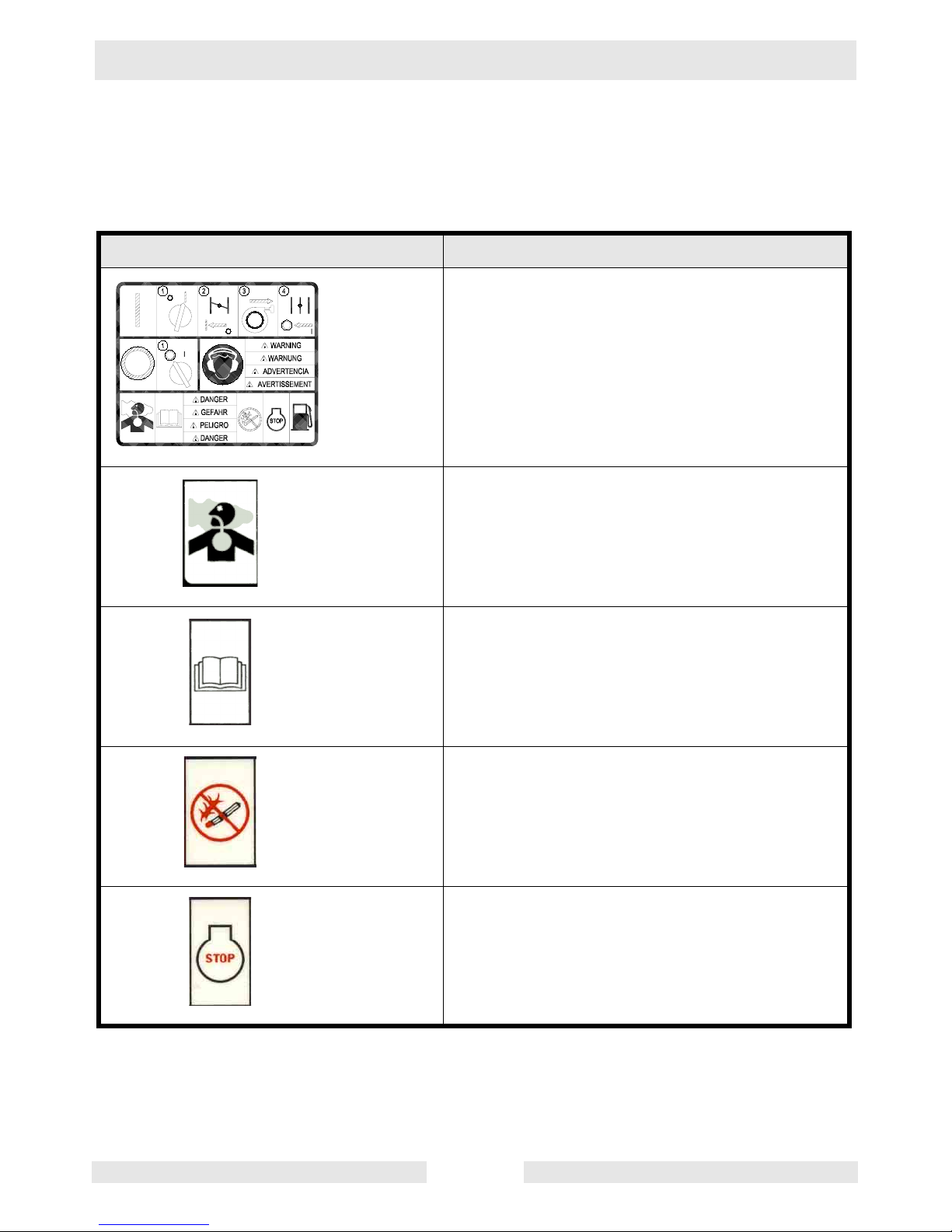
2.5 Safety Labels
Wacker machines use international pictorial labels where needed.
These labels are described below:
Label Meaning
This molded-in label contains important safety
and operating information. If it becomes illegible, the cover must be replaced. Refer to the
Parts Book for ordering information.
DANGER!
Engines emit carbon monoxide; operate only in
well-ventilated area.
Read the operator's manual for machine information.
DANGER!
No sparks, flames or burning objects near
machine.
Shut off the engine before refueling.
wc_si000143gb.fm 18
WM 90 Repair Safety Information
Label Meaning
CAUTION!
Use only clean, filtered gasoline fuel.
WARNING!
Hot surface!
WARNING!
Serious injury if struck by compressed spring
or cover. If the spring system cover is removed
improperly, the springs can eject.
Guaranteed sound power level in dB(A).
CAUTION!
Use only clean, filtered gasoline fuel.
wc_si000143gb.fm 19
Safety Information WM 90 Repair
Label Meaning
A nameplate listing the model number, item
number, revision number, and serial number is
attached to each unit. Please record the information found on this plate so it will be available
should the nameplate become lost or damaged. When ordering parts or requesting service information, you will always be asked to
specify the model number, item number, revision number, and serial number of the unit.
This machine may be covered by one or more
patents.
wc_si000143gb.fm 20
WM 90 Repair Safety Information
2.6 Operating Labels
Wacker machines use international pictorial labels where needed.
These labels are described below:
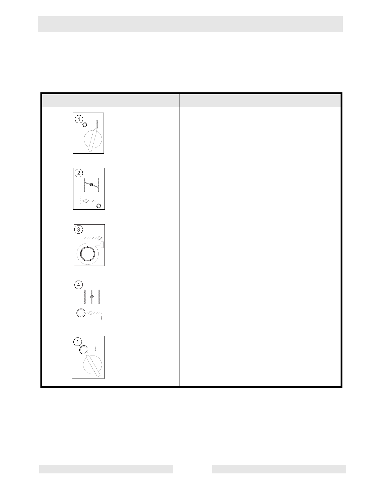
Label Meaning
Turn the engine switch to the ON position.
Close the choke.
Pull the rewind starter.
Open the choke.
Turn the engine switch to "OFF".
wc_si000143gb.fm 21
Safety Information WM 90 Repair
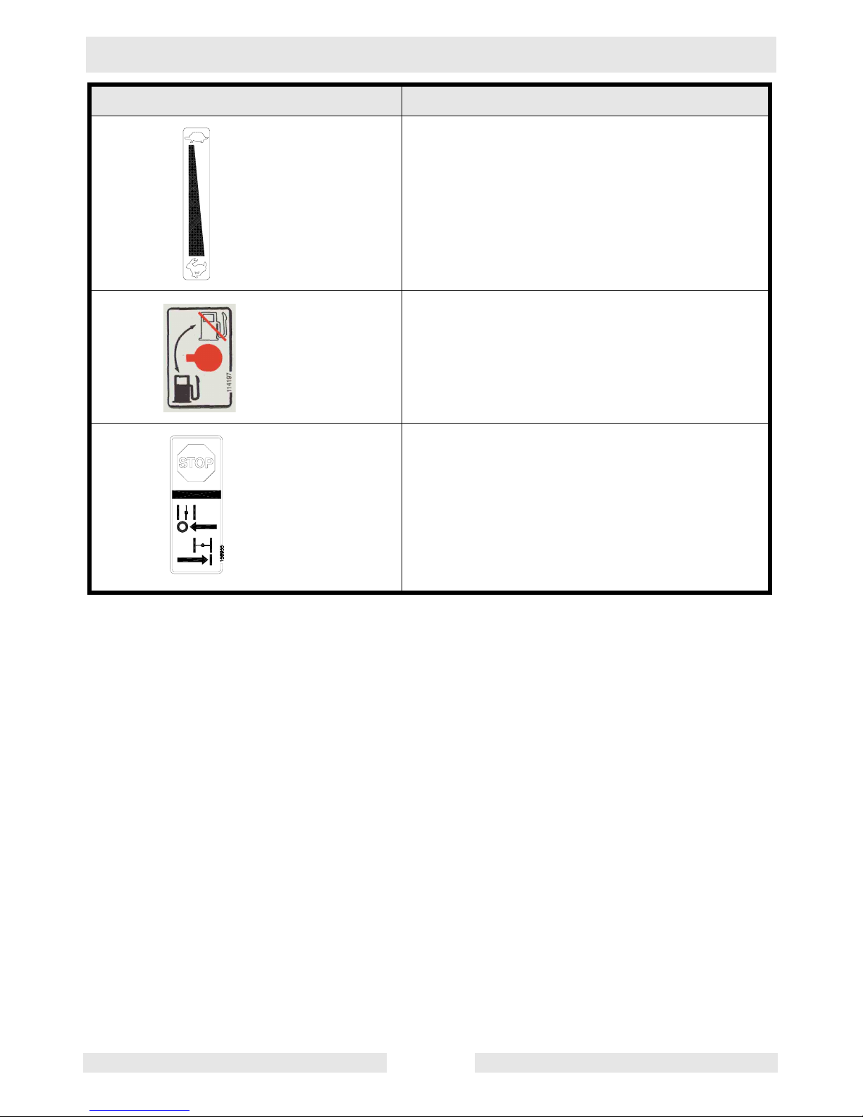
Label Meaning
Throttle control lever:
Turtle = Idle or Slow
Rabbit = Full or Fast
Fuel valve:
Closed
Open
Engine stop button:
Press to stop engine.
Choke:
0 = Open
l = Closed
wc_si000143gb.fm 22
WM 90 Technical Data
3. Technical Data
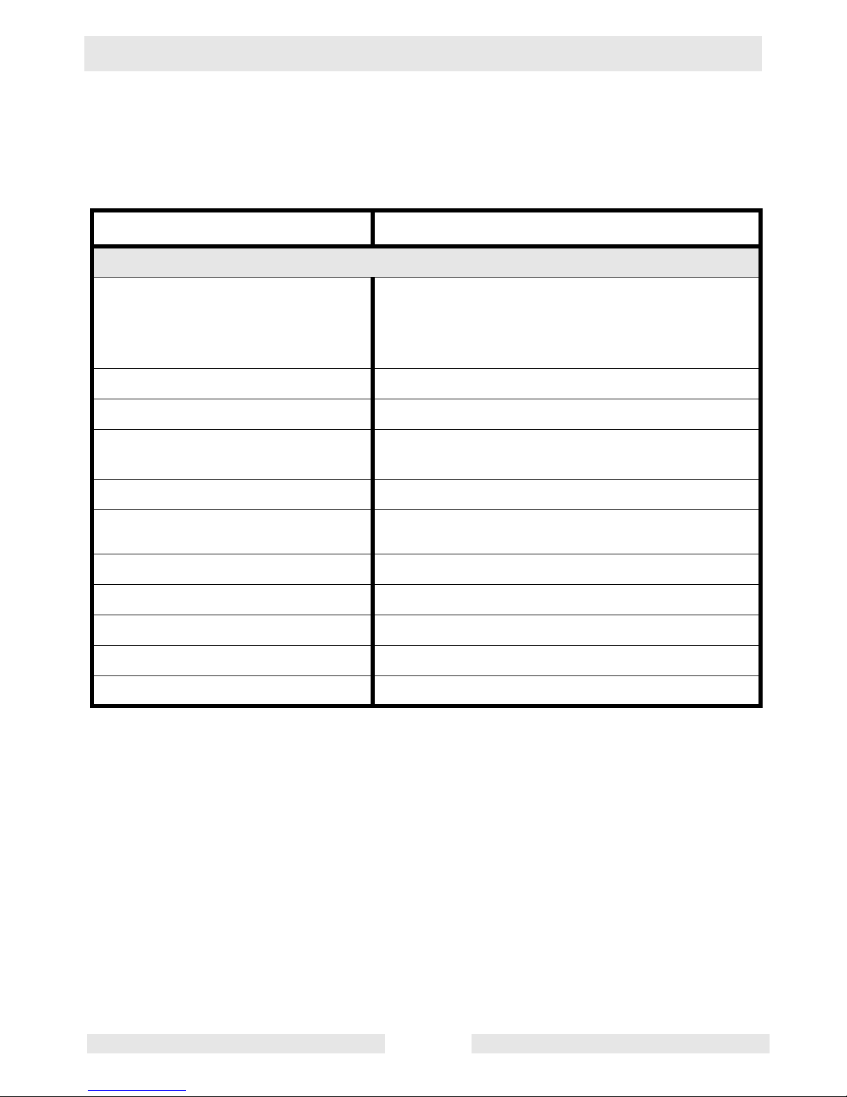
3.1 Specifications
Engine Model
Engine Speed - full
Engine Speed - idle
Clutch Engagement
Spark Plug
Electrode Gap
Cylinder Head
Compression (cold)
Air Cleaner
Engine Lubrication
Engine Oil Capacity
Cooling System
WM 90
Engine
rpm 4200 ± 100
rpm 2000 ± 100
rpm 2500 ± 100
type NGK BM4A or BMR4A
mm (in) 0.6–0.7 (0.023–0.028)
(kg/cm2)
psi
type Three-stage with cyclonic precleaner
oil grade SAE 10W30
ml (oz.) 300 (10)
type Forced air
8.0–9.7 (120–140)
SE, SF or higher
Ignition system
Starting system
Governor system
type Solid-state, flywheel magneto
type Recoil starter
type Centrifugal flyweight
wc_td000143gb.fm 23
Technical Data WM 90
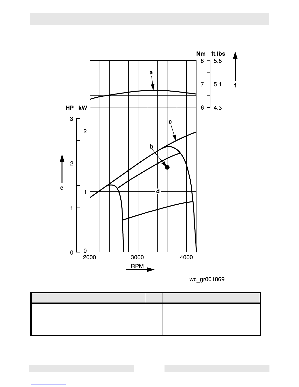
3.2 Performance
Ref Description Ref Description
a Maximum torque d Recommended horsepower range
b Continuous rated horsepower e Output
c Maximum horsepower f Torque
wc_td000143gb.fm 24

WM 90 Theory of Operation
4. Theory of Operation
4.1 Application
Rammers are designed to compact loose soils and gravel to prevent
settling and to provide a firm, solid base for the placement of footings,
concrete slabs, foundations, and other structures.
4.2 Recommended Fuel
This engine is certified to operate on automotive unleaded gasoline.
Use only fresh, clean gasoline. Gasoline containing water or dirt will
damage fuel system.
4.3 Before Starting
4.3.1 Read safety instructions at the beginning of this manual.
4.3.2 Make sure that the gas tank is full.
4.3.3 Check engine oil level.
4.3.4 Place rammer on loose soil or gravel. DO NOT start rammer on hard
surfaces such as asphalt or concrete.
wc_tx000388gb.fm 25
Theory of Operation WM 90
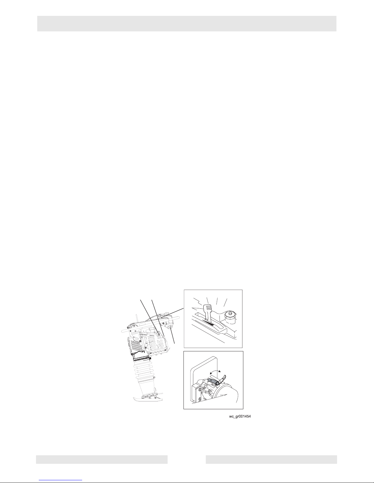
4.4 To Start
See Graphic: wc_gr001454
Note: After transporting the rammer horizontally, upright the rammer
and allow the oil to drain back through the engine. It may take up to 2
minutes for the oil level to recover.
4.4.1 Open fuel valve (e).
4.4.2 Turn engine switch to "ON" (d).
4.4.3 If the engine is cold, close choke (b1) on the carburetor.
Note: Occasionally, warm engines will need to be choked.
4.4.4 With throttle in idle position (c2), pull the starter rope (a) until the
engine starts.
4.4.5 On engines equipped with the low oil shutoff switch, see section Low
Oil Shutoff Switch for additional information.
Note: First time use, engines recently serviced, run out of fuel or not
used for long periods of time may need the rope to be pulled more
times to move fuel to the carburetor.
4.4.6 Open choke (b2) on the carburetor as the engine warms up.
Note: A cold engine should be allowed to warm up at the idle position
(c2) for approximately one (1) minute. Failure to open the choke after
the engine attempts to start may cause flooding.
NOTICE: Always open choke (b2) with throttle in idle position (c2).
Opening choke with throttle not in idle position (c2) may result in
rammer motion.
c3
c2
d
a
c1
e
b2
c4
b1
wc_tx000388gb.fm 26
WM 90 Theory of Operation
4.5 To Stop
See Graphic: wc_gr001454
4.5.1 Place throttle in the idle position (c2).
4.5.2 Turn engine switch to "OFF" (d).
4.5.3 Close fuel valve (e).
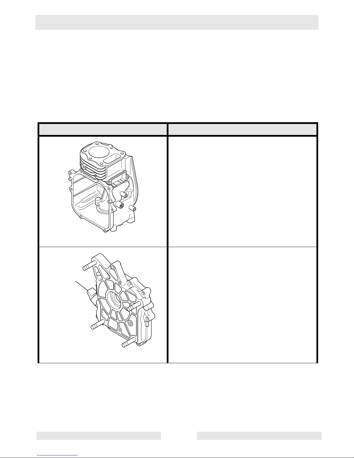
4.6 Component Descriptions
Component Illustration Component Description
The cylinder/crankcase is a single piece aluminum die-casting. The cylinder liner, made of
special cast iron, is molded into the aluminum
casting. The crankcase has a mounting surface on the output shaft side, where the main
bearing cover is attached.
wc_gr001870
The main bearing cover is an aluminum diecasting with thick reinforcing walls and ribs,
which is mounted on the output shaft side of
a
the crankcase. Remove the main bearing
cover to inspect the inside of the engine. Pilots
and bosses are machined on the cover for
direct mounting of the engine onto rammers.
Oil gauge (a).
wc_gr001871
wc_tx000388gb.fm 27
Theory of Operation WM 90
Component Illustration Component Description
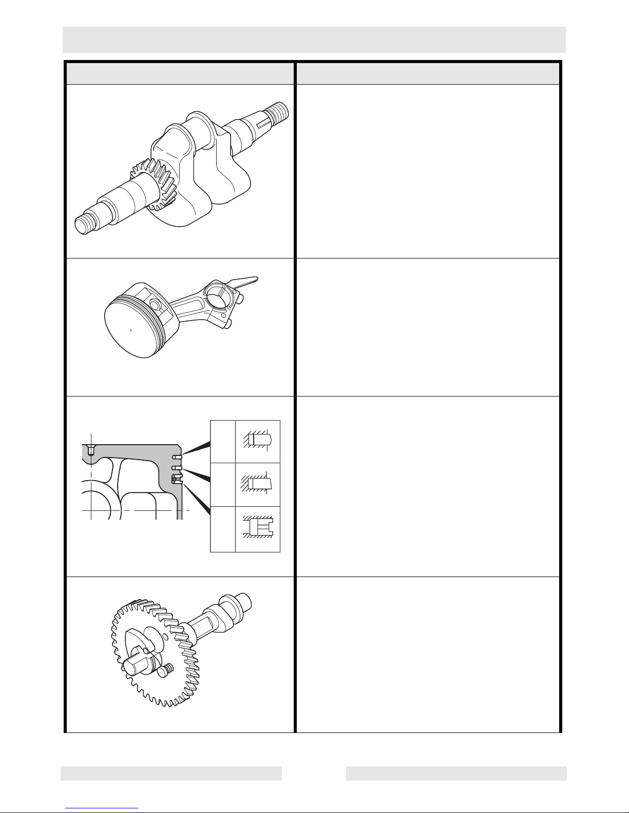
The crankshaft is forged carbon steel, and the
crank pin is induction-hardened. The output
end of the shaft has a crankshaft gear that is
pressed into position.
wc_gr001872
The connecting rod is an aluminum alloy diecasting and its large and small ends function
as bearings. The piston is an aluminum alloy
casting, and carries two compression rings
and one oil ring.
wc_gr001874
wc_gr001873
a
b
c
The piston rings are made of special cast iron.
The profile of the top ring and the second ring
are shown in the illustration. The oil ring is a
three-part ring designed for better sealing and
less oil consumption.
The camshaft is made of special cast iron, and
camshaft and gear are cast together in one
piece. Both sides of the shaft fit into the plain
bearings on the crankcase and main bearing
cover.
wc_gr001875
wc_tx000388gb.fm 28
WM 90 Theory of Operation
Component Illustration Component Description
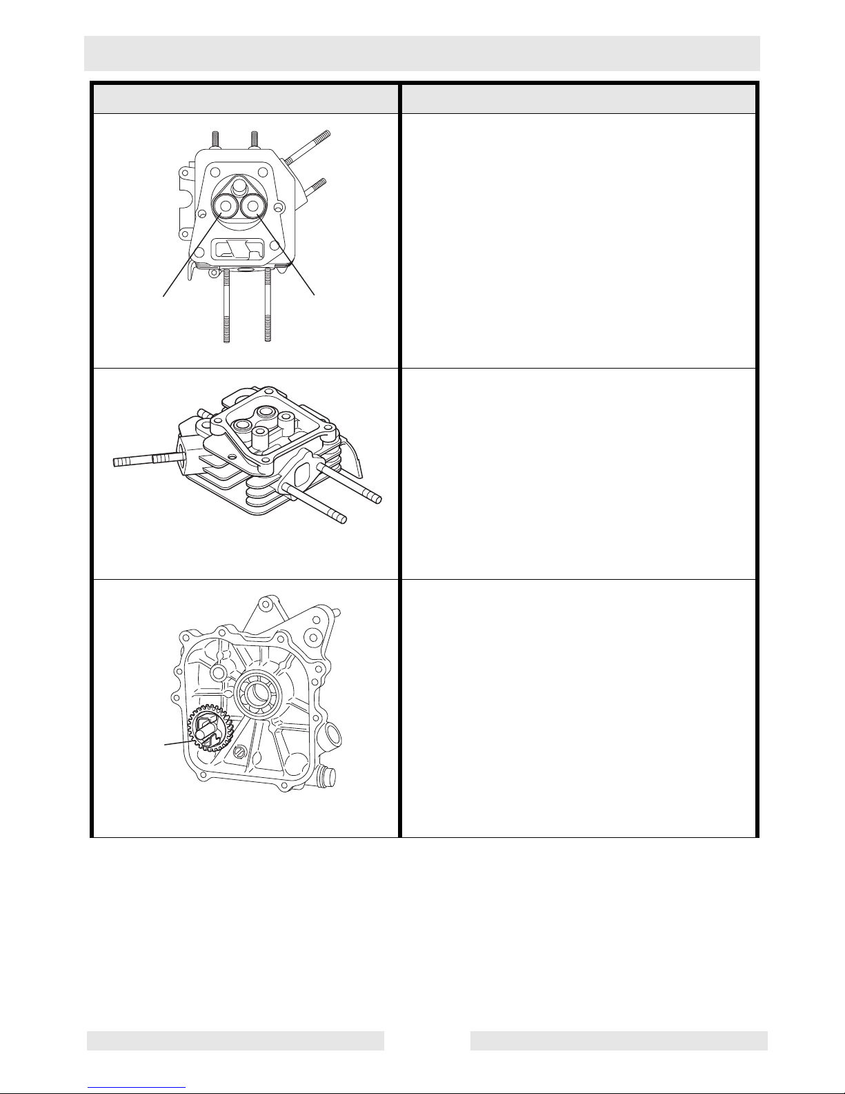
The intake valve is located on the flywheel side
of the cylinder head. Hard alloy valve seats are
molded in the cylinder head and satellite is
fused to the exhaust valve face. The cylinder
IN
EX
ab
wc_gr001876
baffle leads cooling air to the exhaust valve
area for optimum cooling.
Reference: intake (a); exhaust (b).
The cylinder head is an aluminum die-casting
which utilizes wedge-type combustion chamber for high combustion efficiency.
wc_gr001877
The governor is a centrifugal flyweight type
which ensures constant operation at the
selected speed during load variations. The
governor gear (a) with governor weights is
installed on the main bearing cover.
a
wc_gr001878
wc_tx000388gb.fm 29
Theory of Operation WM 90
Component Illustration Component Description
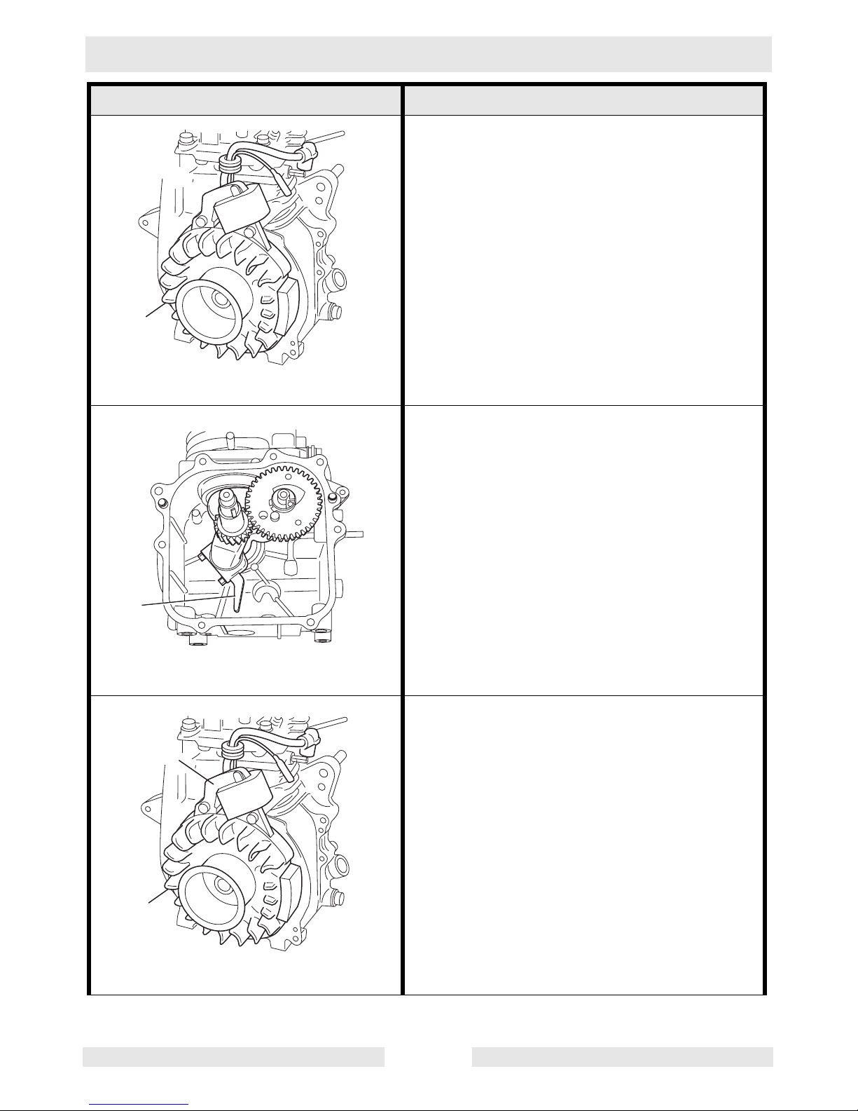
The large fins (a) on the flywheel provide sufficient cooling air capacity for the inlet and
exhaust area and cylinder. The cylinder baffle
directs the cooling air flow efficiently.
a
wc_gr001949
All the rotating and sliding parts are splashlubricated by the oil splasher (a) on the connecting rod.
a
wc_gr001879
The ignition system is a transistor-controlled
magneto system which consists of a flywheel
b
(a) and an ignition coil (b) with a built-in tran-
sistor mounted on the crankcase. This system
has an automatic ignition timing advance system for easy starting.
a
wc_gr001880
wc_tx000388gb.fm 30
 Loading...