

Wacker Neuson WM 80 Repair Manual
Repair Manual
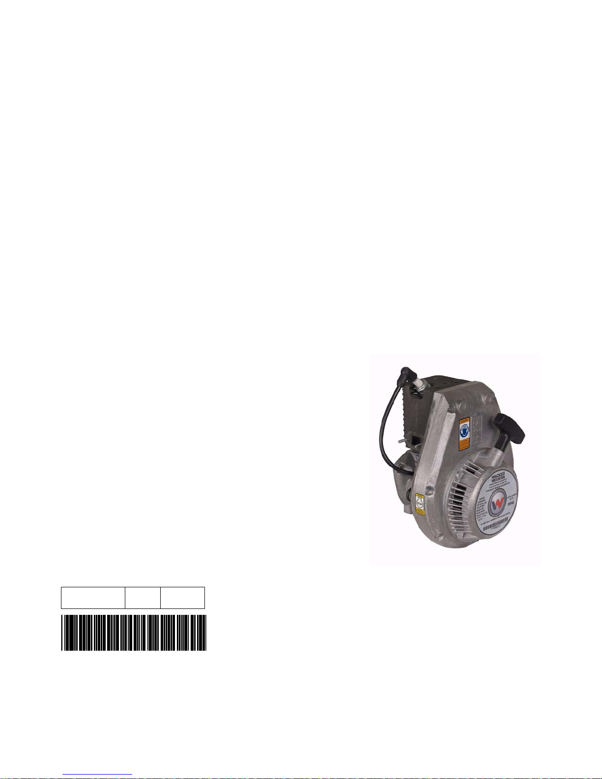
Engine
WM 80
0162695en 003 0610
0162695EN

Copyright
notice
© Copyright 2010 by Wacker Neuson Corporation.
All rights, including copying and distribution rights, are reserved.
This publication may be photocopied by the original purchaser of the machine. Any
other type of reproduction is prohibited without express written permission from
Wacker Neuson Corporation.
Any type of reproduction or distribution not authorized by W acker Neuson Corp oration
represents an infringement of valid copyrights. Violators will be prosecuted.
T ra d emarks
Manufacturer
All trademarks referenced in this manual are the property of their respective owners.
Wacker Neuson Corporation
N92W15000 Anthony Avenue
Menomonee Falls, WI 53051 U.S.A.
Tel: (262) 255-0500 · Fax: (262) 255-0550 · Tel: (800) 770-0957
www.wackerneuson.com

Foreword
Foreword
Machine
documentation
Expectations
for
information in
this manual
CALIFORNIA
Proposition
65 Warning
Keep a copy of the Operator’s Manual with the machine at all times.
Use the separate Parts Book supplied with the machine to order replacement
parts.
If you are missing any of these documents, please contact Wacker Neuson
Corporation to order a replacement or visit www.wackerneuson.com.
When ordering parts or requesting service information, be prepared to provide
the machine model number, item number, revision number, and serial number.
This manual provides information and procedures to repair the above Wacker
Neuson model(s). For your own safety and to reduce the risk of injury , ca refully
read, understand, and observe all instructions described in this manual.
Wacker Neuson Corporation expressly reserves the right to make technical
modifications, even without notice, which improve the performance or safety
standards of its machines.
The information contained in this manual is based on machines manufactured
up until the time of publication. Wacker Neuson Corporation reserves the right
to change any portion of this information without notice.
Engine exhaust, some of its constituents, and certain vehicle components, contain
or emit chemicals known to the State of California to cause cancer and birth
defects or other reproductive harm.
Laws
pertaining to
spark
arresters
Manufacturer’s
approval
NOTICE: State Health Safety Codes and Public Resources Codes specify that in
certain locations spark arresters be used on internal combustion engines that use
hydrocarbon fuels. A spark arrester is a device designed to prevent accidental discharge of sparks or flames from the engine exhaust. Spark arresters are qualified
and rated by the United States Forest Service for this purpose. In order to comply
with local laws regarding spark arresters, consult the engine distributor or the local
Health and Safety Administrator.
This manual contains references to approved parts, attachments, and modifications. The following definitions apply:
Approved parts or attachments are those either manufactured or provided by
Wacker Neuson.
Approved modifications are those performed by an authorized Wacker Neu-
son service center according to written instructions published by Wacker Neuson.
Unapproved parts, attachments, and modifications are those that do not
meet the approved criteria.
Unapproved parts, attachments, or modifications may have the following consequences:
Serious injury hazards to the operator and persons in the work area
Permanent damage to the machine which will not be covered under warranty
Contact your Wacker Neuson dealer immediately if you have questions about
approved or unapproved parts, attachments, or modifications.
wc_tx001528gb.fm 3

Foreword
4 wc_tx001528gb.fm

WM 80 Table of Contents
Foreword 3
1 Safety Information 9
1.1 Signal Words Used in this Manual ....................................................... 9
1.2 Safety Guidelines for Operating the Machine ..................................... 10
1.3 Operator Safety while Using Internal Combustion Engines ............... 12
1.4 Service Safety .................................................................................... 13
2 Technical Data 14
2.1 Engine Specifications ......................................................................... 14
2.2 Tune-up Specifications ....................................................................... 15
2.3 Carburetor Specifications for Bing, and Tillotson (Standard**) .......... 16
2.4 Operating and Idle Speeds ................................................................. 19
3 Maintenance 20
3.1 Periodic Maintenance Schedule ......................................................... 20
3.2 Storage ............................................................................................... 21
3.3 General Air Filter Maintenance ........................................................... 21
3.4 Cartridge-Type Air Filter ..................................................................... 22
3.5 Disc-Type Air Filter ............................................................................. 23
3.6 Low-Maintenance Air Filter ................................................................. 24
3.7 Dual-Element Air Cleaner ................................................................... 25
3.8 Three-Stage Air Cleaners ................................................................... 26
3.9 Engine Cleaning ................................................................................. 28
3.10 Spark Plug .......................................................................................... 28
3.11 Muffler ................................................................................................ 28
3.12 Fuel Filter ........................................................................................... 30
3.13 Fuel Hoses ......................................................................................... 30
4 Starting and Ignition 31
4.1 Starter Assembly Exploded View ....................................................... 31
4.2 Disassembling the Starter .................................................................. 32
wc_br0162695en_003TOC.fm 5

Table of Contents WM 80
4.3 Inspecting the Starter ..........................................................................32
4.4 Assembling the Starter ........................................................................33
4.5 Replacing the Starter Rope .................................................................34
4.6 Ignition System Diagram ...................................................................36
4.7 Ignition System Operation ...................................................................37
4.8 Checking Spark ...................................................................................38
4.9 Using Ignition Tester ...........................................................................39
4.10 Setting Air Gap ....................................................................................40
4.11 Replacing the Ignition Module .............................................................42
5 Carburetor Basics 46
5.1 Brands Used ........................................................................................46
5.2 Walbro Carburetor Operation ..............................................................47
5.3 Versions of Tillotson Carburetor ..........................................................54
5.4 Tillotson Carburetor Operation ............................................................55
5.5 Bing Carburetor Operation ..................................................................61
5.6 Carburetor Adapters ............................................................................64
6 Carburetor Replacement 66
6.1 Replacing the Walbro Carburetor (auto-release choke models) .........66
6.2 Removing Walbro Carburetor (standard choke models) .....................70
6.3 Removal, Tillotson with composite adapter .........................................72
6.4 Tillotson with Straight-Through Adapters ............................................74
6.5 Tillotson with Elbow Adapters .............................................................74
6.6 Bing .....................................................................................................75
7 Carburetor Overhaul 76
7.1 Walbro Carburetor Exploded View (auto-release choke models) .......76
7.2 Walbro Carburetor Components (auto-release choke models) ...........77
7.3 Rebuilding the Walbro Carburetor (auto-release choke models) ........78
7.4 Walbro Carburetor Exploded View (standard choke models) .............84
7.5 Walbro Carburetor Components (standard choke models) .................85
7.6 Rebuilding the Walbro Carburetor (standard choke models) ..............86
7.7 Tillotson Carburetor Exploded View ..................................................92
7.8 Tillotson Components ..........................................................................93
6 wc_br0162695en_003TOC.fm

WM 80 Table of Contents
7.9 Bing Carburetor Exploded View ......................................................... 94
7.10 Bing Carburetor Components ............................................................. 95
8 Carburetor Inspection and Adjustment 96
8.1 Inspection ........................................................................................... 96
8.2 Adjusting the Inlet Control Lever ........................................................ 97
8.3 Carburetor Adjustments ..................................................................... 98
9 Carburetor Troubleshooting 101
9.1 Troubleshooting Walbro Carburetors ............................................... 101
9.2 Troubleshooting Tillotson and Bing Carburetors .............................. 102
10 Disassembly and Assembly 104
10.1 Tools ................................................................................................. 104
10.2 Special Tools .................................................................................... 104
10.3 Ordering Parts ................ .................................................................. 105
10.4 Reference Numbers ( ) ..................................................................... 105
10.5 Threadlocking Compounds .............................................................. 105
10.6 Removing the WM 80 Engine from BS Rammers (auto-release
choke models) .................................................................................. 106
10.7 Removing Engine From BS Model Rammers
(standard choke models) .................................................................. 108
10.8 Removing Engine From BH 23 Breakers ......................................... 110
10.9 Removing Clutch .............................................................................. 112
10.10 WM 80 Exploded View .................................................................... 114
10.11 WM 80 Components ......................................................................... 115
10.12 WM 80 Cross Section ..................................................................... 116
10.13 WM 80 Cross Section Components ................................................. 117
10.14 Vacuum Testing Cylinder ................................................................. 118
10.15 Cylinder and Piston Removal ........................................................... 120
10.16 Cylinder and Piston Inspection ......................................................... 122
10.17 Cylinder and Piston Installation ........................................................ 124
10.18 Inspecting Connecting Rod and Crankshaft ..................................... 126
10.19 Disassembling Crankcase ................................................................ 128
10.20 Assembling Crankcase ..................................................................... 130
wc_br0162695en_003TOC.fm 7

Table of Contents WM 80
10.21 Crankshaft Bearings ..........................................................................132
10.22 Bearing Installation ............................................................................134
8 wc_br0162695en_003TOC.fm
WM 80 Safety Information
1 Safety Information
1.1 Signal Words Used in this Manual
This manual contains DANGER, WARNING, CAUTION, NOTICE, and
NOTE signal words which must be followed to reduce the possibility
of personal injury, damage to the equipment, or improper service.
This is the safety alert symbol. It is used to alert you to potential personal hazards.
f Obey all safety messages that follow this symbol.
DANGER
DANGER indicates a hazardous situation which, if not avoided, will result in death
or serious injury.
f
To avoid death or serious injury from this type of hazard, obey all safety messages that
follow this signal word.
WARNING
WARNING indicates a hazardous situation which, if not avoided, could result in
death or serious injury.
To avoid possible death or serious injury from this type of hazard, obey all safety mes-
f
sages that follow this signal word.
CAUTION!
CAUTION indicates a hazardous situation which, if not avoided, could result in
minor or moderate injury.
f
To avoid possible minor or moderate injury from this type of hazard, obey all safety messages that follow this signal word.
NOTICE: Used without the safety alert symbol, NOTICE indicates a
situation which, if not avoided, could result in property damage.
Note: A Note contains additional information important to a procedure.
wc_si000509gb.fm 9

Safety Information WM 80
1.2 Safety Guidelines for Operating the Machine
Operator qualifications
Only trained personnel are permitted to start, operate, and shut down
the machine. They also must meet the following qualifications:
• have received instruction on how to properly use the machine
• are familiar with required safety devices
The machine must not be accessed or operated by:
• children
• people impaired by alcohol or drugs
Operator training
Before operating the machine:
• Read and understand the operating instructions contained in all
manuals delivered with the machine.
• Familiarize yourself with the location and proper use of all
controls and safety devices.
• Contact Wacker Neuson Corpor ation for additional training if
necessary.
When operating this machine:
• Do not allow improperly trained people to operate the machine.
People operating the machine must be familiar with the potential
risks and hazards associated with it.
Personal Protective Equipment (PPE)
Wear the following Personal Protective Equipment (PPE) while
operating this machine:
• Close-fitting work clothes that do not hinder movement
• Safety glasses with side shields
• Hearing protection
• Safety-toed footwear
1.2.1 Never operate this machine in applications for which it is not intended.
1.2.2 Do not allow anyone to operate this equipment without proper training.
People operating this equipment must be familiar with the risks and
hazards associated with it.
1.2.3 Do not touch the engine or muffler while the engine is on or
immediately after it has been turned off. These areas get hot and may
cause burns.
1.2.4 Do not operate the machine with unapproved accessories or
attachments.
1.2.5 Never leave the machine running unattended.
10 wc_si000509gb.fm

WM 80 Safety Information
1.2.6 Never tamper with or disable the function of operating controls.
1.2.7 Never use the choke to stop the engine.
1.2.8 Never operate the machine in areas where explosions may occur.
1.2.9 Read, understand, and follow procedures in the Operator’s Manual
before attempting to operate the machine.
1.2.10 Make sure that all other persons are at a safe distance from the
machine. Stop the machine if people step into the working area of the
machine.
1.2.11 Be sure operator is familiar with proper safety precautions and
operation techniques before using machine.
1.2.12 Always keep hands, feet, and loose clothing away from moving parts
of the machine.
1.2.13 Always use common sense and caution when operating the machine.
1.2.14 Always be sure the rammer will not tip over, roll, slide, or fall when not
being operated.
1.2.15 Always turn the engine OFF when the rammer is not being operated.
1.2.16 Always guide the rammer in such a way that the operator is not
squeezed between the rammer and solid objects. Special care is
required when working on uneven ground or when compacting coarse
material. Make sure to stand firmly when operating the machine under
such conditions.
1.2.17 When working near the edges of breaks, pits, slopes, trenches and
platforms, always operate the rammer in such a way that there is no
danger of it tipping over or falling in.
1.2.18 Store the machine properly when it is not being used. The machine
should be stored in a clean, dry location out of the reach of children.
1.2.19 Close fuel valve on engines equipped with one when machine is not
being operated.
1.2.20 Always operate machine with all safety devices and guards in place
and in working order. Do not modify or defeat safety devices. Do not
operate machine if any safety devices or guards are missing or
inoperative.
1.2.21 Do not transport the machine while it is running.
1.2.22 Do not tip the machine for cleaning or for any other reason.
wc_si000509gb.fm 11
Safety Information WM 80
1.3 Operator Safety while Using Internal Combustion Engines
WARNING
Internal combustion engines present special hazards during operation and fueling. Failure to
follow the warnings and safety standards could result in severe injury or death.
f Read and follow the warning instructions in the engine owner’s manual and the
safety guidelines below.
DANGER
Exhaust gas from the engine contains carbon monoxide, a deadly poison. Exposure to carbon monoxide can kill you in minutes.
f NEVER operate the machine inside an enclosed area, such as a tunnel, unless
adequate ventilation is provided through such items as exhaust fans or hoses.
Operating safety
When running the engine:
• Keep the area around exhaust pipe free of flammable materials.
• Check the fuel lines and the fuel tank for leaks and cracks before
starting the engine. Do not run the machine if fuel leaks are present
or the fuel lines are loose.
When running the engine:
• Do not smoke while operating the machine.
• Do not run the engine near sparks or open flames.
• Do not touch the engine or muffler while the engine is running or
immediately after it has been turned off.
• Do not operate a machine when its fuel cap is loose or missing.
• Do not start the engine if fuel has spilled or a fuel odor is present.
Move the machine away from the spill and wipe the machine dry
before starting.
Refueling safety
When refueling the engine:
• Clean up any spilled fuel immediately.
• Refill the fuel tank in a well-ventilated area.
• Replace the fuel tank cap after refueling.
• Do not smoke.
• Do not refuel a hot or running engine.
• Do not refuel the engine near sparks or open flames.
12 wc_si000509gb.fm

WM 80 Safety Information
• Do not refuel if the machine is positioned in a truck fitted with a
plastic bed liner. Static electricity can ignite the fuel or fuel vapors.
1.4 Service Safety
A poorly maintained machine can become a safety hazard! In order
for the machine to operate safely and properly over a long period of
time, periodic maintenance and occasional repairs are necessary.
WARNING
1.4.1 Do not attempt to clean or service the machine while it is running.
Rotating parts can cause severe injury.
1.4.2 DO NOT operate the machine without an air cleaner.
1.4.3 DO NOT remove air cleaner cover, paper element, or precleaner while
engine is running.
1.4.4 DO NOT alter engine speeds. Run the engine only at speeds specified
in the Technical Data Section.
1.4.5 Do not crank a flooded engine with the spark plug removed on
gasoline-powered engines. Fuel trapped in the cylinder will squirt out
the spark plug opening.
1.4.6 Do not test for spark on gasoline-powered engines if the engine is
flooded or the smell of gasoline is present. A stray spark could ignite
the fumes.
1.4.7 Do not use gasoline or other types of fuels or flammable solvents to
clean parts, especially in enclosed areas. Fumes from fuels and
solvents can become explosive.
1.4.8 ALWAYS replace the safety devices and guards after repairs and
maintenance.
1.4.9 Keep the area around the muffler free of debris such as leaves, paper,
cartons, etc. A hot muffler could ignite the debris and start a fire.
1.4.10 ALWAYS do periodic maintenance as recommended in the Operator’s
Manual.
1.4.11 ALWAYS clean debris from engine cooling fins.
1.4.12 Replace worn or damaged components with spare parts designed and
recommended by Wacker Neuson Corporation.
1.4.13 Disconnect the spark plug on machines equipped with gasoline
engines, before servicing, to avoid accidental start-up.
1.4.14 Keep the machine clean and labels legible. Replace all missing and
hard-to-read labels. Labels provide important operating instructions
and warn of dangers and hazards.
wc_si000509gb.fm 13

Technical Data WM 80 Repair
2 Technical Data
2.1 Engine Specifications
Engine Model WM 80
Type 2-cycle
Maximum rated power (kW) hp 3.0 (4.0)
Number of cylinders 1
Piston displacement cc
80 (4.9)
(cu.in.)
Cylinder bore mm (in.) (45) 1.77
Stroke mm (in.) 50 (1.96)
Compression ratio 9:1
Operating speed range rpm 3,000–5,000
Starter Pull-type, recoil starter
Ignition Transistor-controlled electronic (TCI)
Carburetor Diaphragm
Fuel Gas/oil mixture
Fuel:oil ratio between 120–50:1 (first tank 25:1)
Cooling Forced air
Weight kg (lbs.) 7.8 (17)
Direction of rotation Counterclockwise when viewed from drive end
14 wc_td000166gb.fm

WM 80 Repair Technical Data
2.2 Tune-up Specifications
Engine Model
Ring gap:
New
Maximum
mm (in.)
mm (in.)
Cylinder wear:
Maximum bore taper
mm (in.) 0.2 (0.008)
Cylinder head
compression
Ignition module air gap*
kg/cc (psi) 8.0–9.7 (120–140)
mm (in.) 0.4 (0.016)
Spark plug gap:
Champion RL86C
Champion UJ11G
Champion RL95YC**
* On models with adjustable air gap
** Must be used on models with oil injection
mm (in.)
mm (in.)
mm (in.)
WM 80
0.2–0.4 (0.008–0.016)
1.0–1.2 (0.039–0.047)
0.5 (0.020)
1.0–1.1 (0.040–0.045)
0.5 (0.020)
wc_td000166gb.fm 15

Technical Data WM 80 Repair
2.3 Carburetor Specifications for Bing, and Tillotson (Standard**)
Machine Carburetor
Make
Low-speed jet
size (x 0.01)
High-speed jet
size (x 0.01)
Carburetor
adapter bore
diameter
mm (in.)
BS 45Y •Bing
•Tillotson
#35
Adjustable
#62
#71*
8 (0.315)
8 (0.315)
•Tillotson w/
idle bypass
#36
#70
8 (0.315)
BS 50 Bing #40 #64 12 (0.472)
BS 52Y •Bing
•Tillotson
#35
Adjustable
#62
#71*
9 (0.354)
9 (0.354)
•Tillotson w/
idle bypass
BS 60Y •Bing
•Tillotson
#36
#35
Adjustable
#70
#62
#71*
9 (0.354)
12 (0.472)
11 (0.433)
•Tillotson w/
idle bypass
BS 62Y •Bing
•Tillotson
#36
#35
Adjustable
#70
#62
#71*
11 (0.433)
12 (0.472)
14 (0.551)
•Tillotson w/
idle bypass
#36
#70
14 (0.551)
BS 65Y
#35 #62 16 (0.630)
BS 100Y #40 #64 16 (0.630)
BPS 1330 #40 #58 10 (0.394)
Bing
BPS 1350 #40 #58 10 (0.394)
BVNPN #40 #64 12 (0.472)
BHF 30S #40 #58 16 (0.630)
BH 23 Tillotson w/ idle
#42 #74 10 (0.394)
bypass
BS 500 7550
Rev. 100–102
BS 500 7550
Tillotson w/ idle
bypass
#36 #78 13 (0.512)
#36 #66 13 (0.512)
Rev. 103–110
16 wc_td000166gb.fm

WM 80 Repair Technical Data
BS 500 7550
Rev. 111–121
BS 500 7550
Rev. >121
BS 500 8048
Rev. 100–102
BS 500 8048
Rev. 103–110
BS 500 8048
Rev. 111–118
BS 500 8048
Rev. >118
BS 500 8049
Rev. 100–102
BS 500 8049
Rev. 103–110
BS 500 8049
Rev. 111–119
Tillotson w/ idle
bypass
#36 #70 13 (0.512)
#36 #70 11 (0.433)
#36 #78 13 (0.512)
#36 #66 13 (0.512)
#36 #70 13 (0.512)
#36 #70 11 (0.433)
#36 #78 13 (0.512)
#36 #66 13 (0.512)
#36 #70 13 (0.512)
BS 500 8049
#36 #70 11 (0.433)
Rev. >120
BS 500 9074
#36 #70 16 (0.630)
High Altitude
Rev. 116
BS 500oi 9166 #36 #72 11 (0.433)
BS 600 7551
#36 #78 14 (0.551)
Rev. 100–103
BS 600 7551
#36 #66 13 (0.512)
Rev. 105–120
BS 600 7551
#36 #72 13 (0.512)
Rev. >121
BS 600 8207
#36 #78 16 (0.630)
High Altitude
Rev. <104
wc_td000166gb.fm 17

Technical Data WM 80 Repair
BS 600 8207
#36 #74 18 (0.709)
High Altitude
Rev. > 104
BS 600oi 9166 #36 #72 18 (0.709)
BS 600oi 9262
#36 #74 18 (0.709)
High Altitude
BS 700 7552
#36 #78 16 (0.630)
Rev. <104
BS 700 7552
#36 #74 18 (0.709)
Rev. 104–118
BS 700 7552
#36 #74 18 (0.709)
Rev. >118
BS 700 8051
#36 #78 16 (0.630)
Rev. 100–120
BS 700 8051
Rev. >120
BS 700 8052
Tillotson w/ idle
bypass
#36 #74 16 (0.630)
#36 #78 16 (0.630)
Rev. 100–102
BS 700 8052
#36 #74 18 (0.709)
Rev. 103–118
BS 700 8052
#36 #74 18 (0.709)
Rev. >118
BS 700oi 9167 #36 #74 18 (0.709)
BS 50-2 9384 #36 #72 19 (0.748)
BS 50-2i 9338 #36 #72 19 (0.748)
BS 50-2i 9383 #36 #72 19 (0.748)
BS 60-2i 9339 #36 #72 19 (0.748)
BS 60-2i 9393 #36 #72 19 (0.748)
BS 70-2i 9341 #36 #72 19 (0.748)
BS 70-2i 9401 #36 #72 19 (0.748)
* Single-needle Tillotson carburetors only. Dual-needle Tillotson carburetors use an adjustable needle
for high-speed adjustment.
** Standard sizes listed. Operation at altitudes above 3000 m (5000 feet) may require different jet and
carburetor adapter sizes. Contact Wacker Neuson Neuson Service for the modifications required.
18 wc_td000166gb.fm

WM 80 Repair Technical Data
2.4 Operating and Idle Speeds
Machine Idle speed ±100 rpm Full speed ±100 rpm
BS 45Y 1800 4300
BS 52Y 1800 4300
BS 60Y 1800 4600
BS 62Y 1800 4500
BS 65Y 1500 4400
BS 100Y 1500 4300
BS 105Y/92Y 1500 4400
BPS 1330 1500 4800
BPS 1350 1500 4800
BVNPN 1700 4500
BHF 30S 1500 4300
BH 23 1500 4250
BS 500 1800 4400
BS 500-oi 1800 4400
BS 50-2 1800 4400
BS 50-2i 1800 4400
BS 600 1800 4350
BS 600-oi 1800 4350
BS 60-2 1800 4350
BS 60-2i 1800 4350
BS 650 1800 4350
BS 65V 1800 4350
BS 700 1800 4350
BS 700-oi 1800 4350
BS 70-2 1800 4350
BS 70-2i 1800 4350
wc_td000166gb.fm 19

Maintenance WM 80
3 Maintenance
3.1 Periodic Maintenance Schedule
Daily After first
5 hours
Check fuel level. •
Clean and/or inspect air filter (cartridge type). •
Clean and oil foam precleaner where equipped. •
Check condition of fuel lines. •
Check & tighten engine cylinder screws. ••
Check & tighten external fasteners. ••
Clean and check spark plug gap. ••
Clean engine cooling fins. •
Replace cartridge style air filter element. •
Replace spark plug. •
Clean recoil starter. •
Remove carbon deposits from muffler & cylinder
exhaust port.
Every
week or
25 Hours
Every
month or
100 Hours
Every 3
months or
300 hours
•
Replace in-line fuel filter. •
Inspect in-tank fuel filter. •
20 wc_tx000520gb.fm

WM 80 Maintenance
3.2 Storage
If storing the unit for a long period of time (more than 30 days) carry
out the following:
3.2.1 Drain fuel from the tank.
3.2.2 Start the engine and run it until all the fuel in the carburetor is used.
3.2.3 Remove the spark plug and pour 30 ml (1 oz.) of clean SAE 30W
engine oil into the cylinder through the spark plug opening.
3.2.4 Pull the starter rope slowly to distribute oil in the engine.
3.2.5 Reinstall the spark plug.
3.3 General Air Filter Maintenance
Inspect the air filter daily. Severe damage to the engine components
can occur if the engine is operated with a damaged element. This is
especially important when operating in extremely dusty conditions; dirt
and sand, if allowed to enter the engine, can quickly destroy the
cylinder wall and piston.
NOTICE: Never operate the engine without an air filter. Damage to the
engine will occur.
wc_tx000520gb.fm 21
Maintenance WM 80
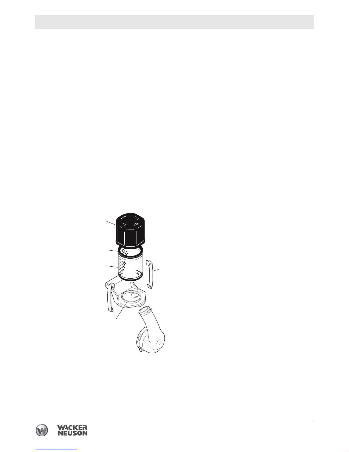
3.4 Cartridge-Type Air Filter
See Graphic: wc_gr002875
3.4.1 This type of air filter is found on rammers with Bing carburetors and on
early rammers with Tillotson carburetors. To service:
3.4.2 Unsnap the spring clips (1) on the protective cover (2) and remove the
filter element (3).
3.4.3 Inspect the paper filter element and replace it if it appears wet, heavily
soiled, or torn.
3.4.4 Inspect the condition of the rubber seals (4) on each end of the
element. Replace the element if the seals are damaged or deformed.
3.4.5 The element can be cleaned by tapping it against a firm surface. Take
care not to damage the seals or puncture the filter paper when
cleaning the filter. Do not use cleaning agents or solvents to clean the
filter.
3.4.6 Clean and inspect the seating surfaces on the mounting base (5) and
inside of the protective cover. Replace any damaged parts. Lightly oil
filter the seals and install the element.
2
3
4
5
1
wc_gr002875
22 wc_tx000520gb.fm
WM 80 Maintenance
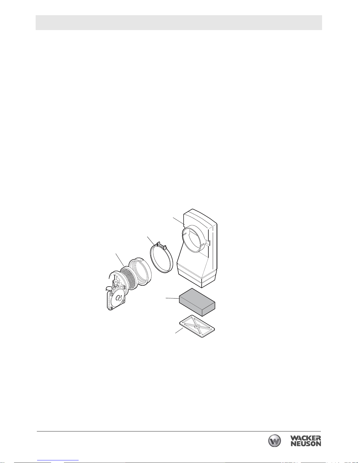
3.5 Disc-Type Air Filter
See Graphic: wc_gr002876
The disc-type air filter with oil-wetted foam precleaner is used on BPS
1330, BPS 1350, BVPN 50, and the BHF 30S. To service the filter:
3.5.1 Close the carburetor choke. Loosen the clamp (1) around the
carburetor and remove the precleaner housing (2).
3.5.2 Remove the metal screen (3) from the carburetor and inspect it.
Replace the screen if it is heavily soiled or damaged. The screen can
be cleaned by tapping it against a firm surface or by using lowpressure (30 psi) compressed air.
3.5.3 Remove the retainer (4) and the foam precleaner (5) from the housing
and inspect. Replace the precleaner if it appears heavily soiled or
damaged. The precleaner can be cleaned by using a mild detergent
and warm water. Rinse it thoroughly and dry it with a lint-free cloth.
3.5.4 After cleaning, soak the precleaner in clean engine oil (SAE 30W),
squeeze out excess oil, and reinstall the filter.
3
2
1
5
4
wc_gr002876
wc_tx000520gb.fm 23

Maintenance WM 80
3.6 Low-Maintenance Air Filter
See Graphic: wc_gr002877
This type of air filter is found on rammers. The air filter is self-cleaning
and uses the movement of the machine to shake dust and dirt loose
from the air filter element while the rammer is operating. Under normal
operating conditions this element will not require cleaning and should
not be removed from the machine. If the element does become
plugged with dirt, the engine will begin to lose power. In this case, the
air filter element can be removed and cleaned as described below.
Replace the element if it becomes so plugged with dirt it can no longer
be cleaned.
3.6.1 Remove the two locknuts from the top of the air filter and lift the air filter
off.
3.6.2 Use compressed air directed from the inside of the air filter, through the
grommet hole (1), to blow dirt and dust from the element.
NOTICE: Air pressure must not exceed 100 psi.
3.6.3 Run fresh water through the grommet hole (1) until water runs clear
NOTICE: DO NOT use solvents, fuel oil, or gasoline to wash the filter.
3.6.4 Plug or cover the hole in the air filter (2) using a cork or tape to prevent
dirty water from entering inside the element. Soak the air filter in a
solution (3) of warm water and a low-suds detergent for at least 15
minutes. Longer periods of time (up to several hours) of soaking may
be required, depending on how dirty the element is.
3.6.5 Remove the air filter from the water and repeat rinsing the filter as
described in Step 3. Allow the element to air dry in a dust-free area.
DO NOT use heat to speed drying.
3.6.6 Inspect the grommet before assembly and replace it if it is worn or
damaged. Install the grommet on the element carefully to avoid cutting
it.
3.6.7 Install the air filter on the machine and secure it with washers and
locknuts. DO NOT overtighten. Overtightening can deform washers
and indent the top of the air filter.
Note: Apply grease or liquid soap to inside of grommet so it slides
easily on machine.
24 wc_tx000520gb.fm
WM 80 Maintenance
1
2
3
wc_gr002877
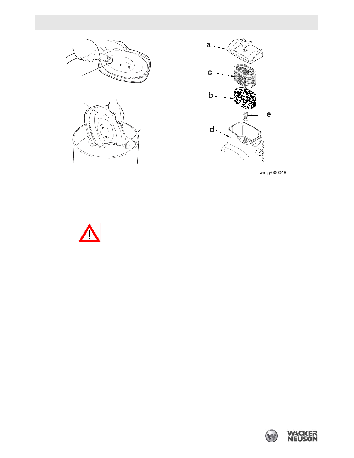
3.7 Dual-Element Air Cleaner
See Graphic: wc_gr000046
NEVER use gasoline or other types of low flash-point solvents for
cleaning the air cleaner. A fire or explosion could result.
WARNING
NOTICE: NEVER run engine without air cleaner. Severe engine
damage will occur.
The rammer is equipped with a dual-element air cleaner. Under normal
operating conditions, elements should be cleaned once every week.
Under severe, dry and dusty conditions, the elements should be
maintained daily. Replace an element when saturated with dirt that
cannot be removed. Clean elements using the following procedure:
3.7.1 Remove air cleaner cover (a). Remove precleaner and paper element
and inspect them for holes or tears. Replace if damaged.
3.7.2 Precleaner (b): Clean with low-pressure compressed air. When very
soiled, wash in solution of mild detergent and warm water. Rinse
thoroughly in clean water. Allow to dry thoroughly before re-installing.
Note: Do not oil precleaner.
3.7.3 Paper element (c): Tap element lightly to remove excess dirt. Replace
paper element if it appears heavily soiled.
3.7.4 Wipe out filter housing (d) with a clean cloth.
NOTICE: Do not allow dirt to get into the engine intake port while
cleaning—damage to the engine will result.
wc_tx000520gb.fm 25

Maintenance WM 80
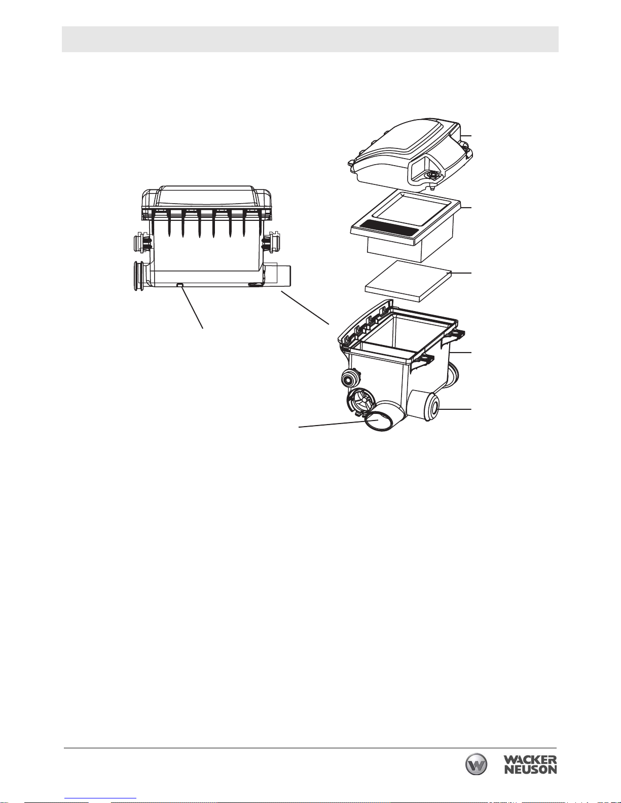
3.8 Three-Stage Air Cleaners
See Graphic: wc_gr001168
NEVER use gasoline or other types of low flash point solvents for
cleaning the air filter. A fire or explosion could result.
WARNING
NOTICE: NEVER run engine without main paper filter element (b).
Severe engine damage will occur.
Filter Indicator
The air intake system is equipped with a filter indicator (h), which
indicates when a filter change is required. Replace the main paper filter
element (b) when the yellow plunger of the indicator appears in or near
the red line. Push and hold in the yellow plunger on top of the indicator
to reset it after replacing the main paper filter element.
Clean elements using the following procedure:
3.8.1 Remove the air cleaner cover (a). Remove the main paper filter
element (b) and the secondary prefilter (c) and inspect them for holes
or tears. Replace the elements if they are damaged.
3.8.2 Main paper filter element (b): Replace the main paper filter element if
it appears heavily soiled and/or when the yellow plunger of indicator
appears in or near the red line.
3.8.3 Prefilter (c): Clean it with low-pressure compressed air. When the
prefilter is very soiled, wash it in a solution of mild detergent and warm
water. Rinse it thoroughly in clean water. Allow the prefilter to dry
thoroughly before reinstalling it.
Note: Do not oil the prefilter.
3.8.4 Wipe out the filter housing (d) with a clean cloth. Do not use
compressed air.
NOTICE: Do not allow dirt to get into the engine intake port (k) while
cleaning. Damage to engine will result.
3.8.5 Check that the precleaner debris ejector slot (i) is clear.
26 wc_tx000520gb.fm
WM 80 Maintenance
a
b
c
i
k
d
h
wc_gr001168
wc_tx000520gb.fm 27

Maintenance WM 80
3.9 Engine Cleaning
The WACKER WM 80 engine is air cooled and depends on the
cylinder cooling fins to dissipate heat. Dirt and debris caught in the
cooling fins can prevent them from dissipating heat causing the engine
to overheat. For this reason, it is important to inspect and clean the fins
as often as job conditions dictate. Clean debris from between the fins
using a screwdriver or similar implement.
3.10 Spark Plug
A well-maintained spark plug is essential to good combustion. Keep
the spark plug’s electrode clean and gapped to the correct setting. See
section Tune-up Specifications. Before removing the spark plug from
the engine, clean the immediate area around the spark plug to prevent
any dirt from falling into the cylinder when the spark plug is removed.
3.11 Muffler
See Graphic: wc_gr005088, wc_gr007375
NOTICE: Do not remove the spark plug while the engine is hot. The
aluminum threads of the cylinder may strip.
Carbon deposits normally form over a period of time at the engine
exhaust and the muffler. If allowed to accumulate, these deposits may
eventually restrict the exhaust passages, resulting in poor
performance and hard starting. Factors contributing to excessive
carbon buildup include:
• Too much oil in the fuel mixture
• Dirty air filter
• Excessive idling
• Dirty carburetor
• Too rich fuel/air mixture
• Incorrect fuel jets
To service the muffler:
3.11.1 Remove the muffler (1, 2) from the engine.
3.11.2 Crank the engine until the piston is at the top of its stroke and covering
the exhaust port.
28 wc_tx000520gb.fm
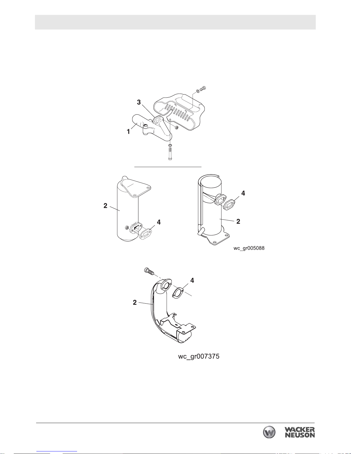
WM 80 Maintenance
3.11.3 Clean the exhaust port using a blunt scraper. Inspect the gasket (3, 4)
and replace it if torn or cracked.
3.11.4 Soak the muffler in carburetor cleaner until the carbon deposits break
up. Drain the muffler and blow dry it dry with compressed air.
wc_tx000520gb.fm 29
Maintenance WM 80
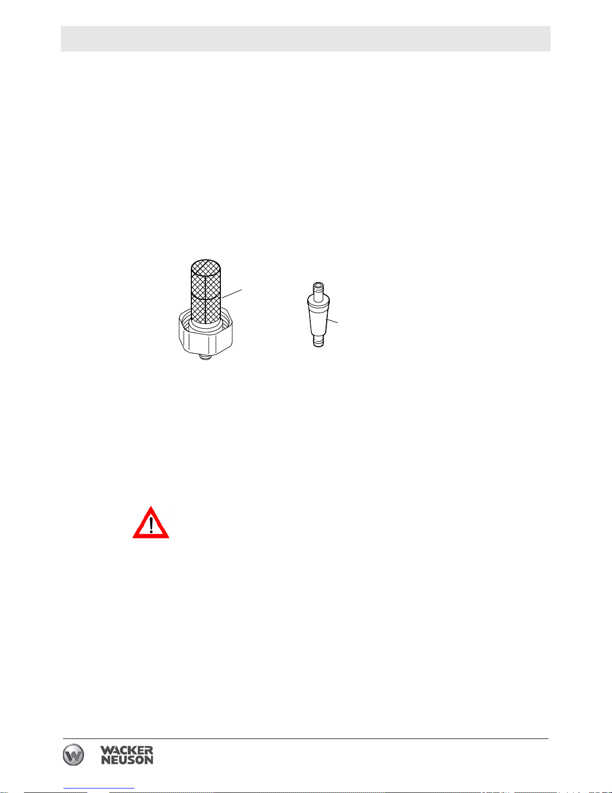
3.12 Fuel Filter
See Graphic: wc_gr002879
Dirt is the primary cause of carburetor problems. Unfiltered fuel can
quickly plug the passages in the carburetor and cause poor
performance. Two different styles of fuel filters are used with the WM
80 engine. One is an in-tank, self-cleaning style (h), the other is an inline replaceable filter (i). No matter the style, it is imperative the fuel
filter be clean. Check in-line fuel filters often and replace at regular
intervals. Check in-tank fuel filters yearly. Clean the filter by back
flushing with solvent. Replace the fuel filter if necessary. See section
Periodic Maintenance Schedule.
h
i
3.13 Fuel Hoses
Check the condition of the fuel hoses frequently and make sure they
are adequately clamped at the tanks and the filters.
Use extreme caution when working on the fuel system. Do not spill fuel
on yourself or others. Clean up any spilled fuel. See section Engine
WARNING
Safety.
wc_gr002879
30 wc_tx000520gb.fm
 Loading...