

Page 1

www.wackerneuson.com
Operator’s Manual
Wheel Loader WL 30
Page 2

December 10 Edition
Page 3

You have opted for a Wacker Neuson loader – thank you very much for putting your trust in us.
Your Wacker Neuson loader is a powerful product with robust technology and a wide range of applications to aid you in
your day-to-day work. In order to familiarize yourself with your loader in a quick, comprehensive manner, please read
this Operator’s Manual attentively.
In addition to the information regarding operation, this Operator’s Manual also contains important maintenance and operating instructions for conserving the value of your loader. Furthermore, we will show you how to operate your loader in
an environmentally sound manner.
Should you have any questions or problems relating to your loader, please contact your Wacker Neuson partner or importer. They will be happy to respond to your questions, suggestions or criticisms at any time.
We are condent that you will be very satised with your new Wacker Neuson loader.
Wacker Neuson SE
Page 4

CO NTE NT S
2
TABLE OF CONTENTS
PREFACE ............................................................................................................................................................... 7
1 BASIC INFORMATION .....................................................................................................................................8
1.1 Notes about this Operator’s Manual ....................................................................................................... 9
1.2 Explanation of the symbols used in this Operator’s Manual ................................................................. 10
1.3 Warranty and liability............................................................................................................................. 12
1.4 Intended use ......................................................................................................................................... 13
2 BASIC SAFETY INSTRUCTIONS .................................................................................................................. 16
2.1 Organizational measures ...................................................................................................................... 17
2.2 Selection and qualication of personnel / basic duties ......................................................................... 19
2.3 Safety instructions for certain operating phases .................................................................................. 20
2.3.1 Safety instructions for normal operation ............................................................................................... 20
2.3.2 Safety instructions for other operating modes ...................................................................................... 22
2.4 Safety instructions for particular hazards ............................................................................................. 25
2.4.1 Forklift attachment ................................................................................................................................ 25
2.4.2 Working near overhead power lines ..................................................................................................... 26
2.4.3 Electrical power..................................................................................................................................... 27
2.4.4 Flying sparks / re danger ..................................................................................................................... 27
2.4.5 Gas, dust, steam, smoke ......................................................................................................................28
2.4.6 Hydraulics, pneumatics ......................................................................................................................... 28
2.4.7 Tip-overs ............................................................................................................................................... 29
2.4.8 Noise ..................................................................................................................................................... 29
2.4.9 Oils, grease and other chemical substances ........................................................................................ 29
2.5 Transporting and towing / restarting ..................................................................................................... 30
Page 5

CO NTE NT S
3
W L 3 0
2.6 Final decommissioning / dismantling .................................................................................................... 30
2.7 Safety labels used ................................................................................................................................. 31
2.8 Safety devices ....................................................................................................................................... 36
2.8.1 Fire extinguisher ................................................................................................................................... 36
2.8.2 Rotating beacon .................................................................................................................................... 36
2.8.3 Seat belt ................................................................................................................................................ 37
2.8.4 Backup alarm for reverse drive ............................................................................................................. 37
2.8.5 Emergency exit ..................................................................................................................................... 38
2.8.6 Battery disconnect switch ..................................................................................................................... 39
2.8.7 Loader lift arm locking system .............................................................................................................. 40
3 TECHNICAL DATA .......................................................................................................................................... 41
3.1 Technical description ............................................................................................................................ 41
3.2 Loader data ........................................................................................................................................... 43
3.3 Product identication number plates ..................................................................................................... 45
3.4 Dimensions ...........................................................................................................................................46
4 DESCRIPTION OF THE INDICATOR, WARNING AND CONTROL ELEMENTS ......................................... 48
4.1 Operating elements and instruments .................................................................................................... 48
4.2 Control and warning indicator lights ...................................................................................................... 50
4.3 Switches / rocker switches .................................................................................................................... 54
4.4 Indicator devices ................................................................................................................................... 58
5 OPERATING AND OPERATION .................................................................................................................... 60
5.1 Before starting up .................................................................................................................................60
Page 6

CO NTE NT S
4
5.1.1 Fueling .................................................................................................................................................. 60
5.1.2 Operation ..............................................................................................................................................62
5.1.3 Doors and windows............................................................................................................................... 64
5.1.4 Adjusting the steering column ............................................................................................................... 65
5.1.5 Adjusting the operator’s seat ................................................................................................................ 66
5.1.6 Seat belt ................................................................................................................................................ 67
5.2 Starting up ............................................................................................................................................ 70
5.2.1 Lighting system and forward warning device ........................................................................................ 70
5.2.2 Wipers and windshield washer system ................................................................................................. 72
5.2.3 Headlights and rotating beacon ............................................................................................................ 74
5.2.4 Ventilation and heating of the cab ......................................................................................................... 76
5.2.5 Before starting the engine ..................................................................................................................... 77
5.2.6 Starting the engine ................................................................................................................................ 78
5.3 Propulsion operation ............................................................................................................................. 80
5.3.1 Preparation for travel in public trafc .................................................................................................... 80
5.3.2 Travel speed .......................................................................................................................................... 81
5.3.3 Stopping and parking ............................................................................................................................ 85
5.4 Work operation ...................................................................................................................................... 86
5.4.1 Operating lever for Loader lift arms ...................................................................................................... 88
5.4.2 Activating the optional hydraulics .......................................................................................................... 90
5.4.3 Loader lift arms locking system ............................................................................................................94
5.4.4 Differential lock ..................................................................................................................................... 95
5.4.5 Changing attachments .......................................................................................................................... 96
5.4.6 Bucket ................................................................................................................................................. 101
5.4.7 Tip-overs ............................................................................................................................................. 107
5.4.8 Precaution measures for various temperature conditions .................................................................. 108
Page 7

CO NTE NT S
5
W L 3 0
5.5 Optional equipment ..............................................................................................................................110
6 TOWING AND TRANSPORTING ..................................................................................................................114
6.1 Towing ..................................................................................................................................................114
6.2 Transporting .........................................................................................................................................118
7 LOWERING LOADER ARMS........................................................................................................................ 125
8 RELIEVING RESIDUAL PRESSURE IN THE HYDRAULIC SYSTEM ........................................................ 126
9 SECURING THE LOADER ........................................................................................................................... 129
10 SERVICING AND INSPECTION ................................................................................................................... 130
10.1 Basic safety instructions for servicing and inspection ........................................................................ 130
10.2 Servicing and inspection intervals ...................................................................................................... 138
10.3 Lubrication schedule ........................................................................................................................... 150
10.4 Cleaning the loader ............................................................................................................................. 152
10.5 General safety check .......................................................................................................................... 154
10.6 Specications and lling quantities ..................................................................................................... 155
10.7 Maintenance and inspection work ...................................................................................................... 156
10.7.1 Preparation for maintenance and inspection work.............................................................................. 156
10.7.2 Servicing the engine ........................................................................................................................... 162
10.7.3 Servicing the fuel system .................................................................................................................... 168
10.7.4 Servicing the air lter system .............................................................................................................. 173
10.7.5 Servicing the cooling system .............................................................................................................. 176
10.7.6 Servicing the hydraulic system ........................................................................................................... 182
Page 8

CO NTE NT S
6
10.7.7 Servicing the axles.............................................................................................................................. 191
10.7.8 Servicing the cab vent lter ................................................................................................................. 195
10.7.9 Servicing the brakes ........................................................................................................................... 196
10.7.10 Servicing the tires and wheels ............................................................................................................ 198
10.7.11 Servicing the electrical system ........................................................................................................... 202
10.8 Jump-starting / emergency starting .................................................................................................... 210
10.9 Loader storage .................................................................................................................................... 213
11 TROUBLESHOOTING AND EMERGENCY MAINTENANCE ...................................................................... 216
12 SAFETY INSTRUCTIONS FOR REPAIRS ................................................................................................... 220
12.1 General safety regulations for repairs ................................................................................................. 220
12.2 Engine ................................................................................................................................................. 223
12.3 Welding work ...................................................................................................................................... 223
12.4 Hydraulic system ................................................................................................................................. 225
12.5 Brakes ................................................................................................................................................. 225
13 FINAL SHUTDOWN OF THE LOADER / DECOMMISSIONING .................................................................226
14 APPENDIX .................................................................................................................................................... 228
14.1 Ordering replacement parts ................................................................................................................ 228
14.2 Inspection verication .........................................................................................................................230
Index ............................................................................................................................................................ 234
List of gures ...................................................................................................................................................... 238
Page 9

PR E FA C E
7
W L 3 0
PREFACE
This Operator’s Manual describes how to operate and
service the loader. It provides operating and maintenance
personnel with the necessary knowledge of the loader‘s
functional characteristics in order to allow them to operate,
diagnose, maintain and repair the loader safely.
Observing the specications in this Operator’s Manual assures:
• proper, safe, professional operation of the loader
• professional service, cleaning and care of the loader
Observe the applicable OSHA 1910 and 1926 safety regulations when they apply to the user.
If required, the user/operator should supplement the Operator’s Manual with instructions and regulations regarding
environmental protection and national regulations relating
to accident prevention.
All persons involved in work on or with the loader must
read and apply this Operator’s Manual, for example with
regard to:
• operation, including setup, maintenance during operation, care, disposal of auxiliary materials and operating
materials as well as disposal of the entire loader.
• maintenance (inspection, servicing, care).
• transport.
Should you have questions about this Operator’s Manual, please contact your dealer or visit us at www.wackerneuson.com.
The Operator’s Manual must always be located in
the loader or at the place where it is being used.
This Operator’s Manual is not designed for purposes of extensive maintenance work. Such work
must be performed by approved professionals.
Page 10

B A S I C I N F O R MAT I O N
8
Each new user must be instructed before using the loader
for the rst time.
Instructions for using the Operator’s Manual:
•
Read the Operator’s Manual carefully before starting
up the loader
• Observe all the safety instructions
• Follow the regulations and laws applicable at the place
of use
• Keep the Operator’s Manual in the protected compart-
ment provided in the operator station/cab.
1 BASIC INFORMATION
If it is not possible to rule out hazards to persons or material
during work according to the loader‘s intended use, these
hazards will be indicated by means of safety labels.
Instructions relate to the direction of travel of the loader;
this means that, when directional information is given, it
can be assumed that this refers to the direction of travel
of the loader.
Page 11

B A S I C I N F O R MAT I O N
9
W L 3 0
1.1 Notes about this Operator’s Manual
The specications, illustrations, weight information and
technical data are not binding and correspond to the state
of the art at the time of printing. We must reserve the right
to make changes without prior notice in the area of design,
conguration, appearance and technology on account of
the ongoing further development of the products.
Contact your dealer for clarication of use and/or instructions concerning intended use and attachments identied
in this Operator’s Manual.
Always strictly observe the safety instructions in this Operator’s Manual and the legal and trade association regulations
at the usage location.
This Manual provides information and procedures to safely
operate and maintain this Wheel Loader. For your own safety
and to reduce the risk of injury, carefully read, understand,
and observe all instructions described in this Manual.
Wacker Neuson Corporation expressly reserves the right
to make technical modications, even without notice, which
improve the performance or safety standards of its machines. The information contained in this manual is based
on machines manufactured up until the time of publication.
Wacker Neuson Corporation reserves the right to change
any portion of this information without notice.
Page 12

B A S I C I N F O R MAT I O N
10
1.2 Explanation of the symbols used in this Operator’s Manual
To ensure safe operation and maintenance of the wheel
loader, it is necessary that you follow all the instructions in
this Operator’s Manual.
The following symbols and the signal words DANGER,
WARNING, CAUTION, NOTICE, and NOTE, and the adjacent text, indicate hazards and instructions.
This is the safety alert symbol. It is used to alert
you to potential personal hazards.
► Obey all safety messages that follow this sym-
bol.
DANGER
DANGER indicates a hazardous situation which,
if not avoided, will result in death or serious injury.
►
Obey all safety messages that follow this symbol
to avoid injury or death.
WARNING
WARNING indicates a hazardous situation which, if
not avoided, could result in death or serious injury.
►
Obey all safety messages that follow this symbol
to avoid possible injury or death.
Page 13

B A S I C I N F O R MAT I O N
11
W L 3 0
CAUTION
CAUTION indicates a hazardous situation which,
if not avoided, could result in minor or moderate
injury.
►
Obey all safety messages that follow this symbol
to avoid possible minor or moderate injury.
NOTICE: Used without the safety alert symbol,
NOTICE indicates a situation which, if not avoided,
could result in property damage.
Important general instructions
ENVIRONMENTAL NOTE
Important general instructions for environmental
protection
Note: Contains additional information important to
a procedure.
Page 14
B A S I C I N F O R MAT I O N
12
1.3 Warranty and liability
Observe the following points:
• Do not make any changes to the wheel loader.
•
Use only Wacker Neuson-approved attachments for
your loader.
• The loader many only be started up, operated and serviced as described in the Operator’s Manual.
• Use the loader only if all the safety and protection devices are intact.
• Observe the monitoring systems during operation.
• Repairs may only be perform by trained professionals.
• Follow the Operator’s Manual exactly.
The manufacturer/supplier is not liable for damage
resulting from unintended use. The operator/user
is the sole bearer of this risk.
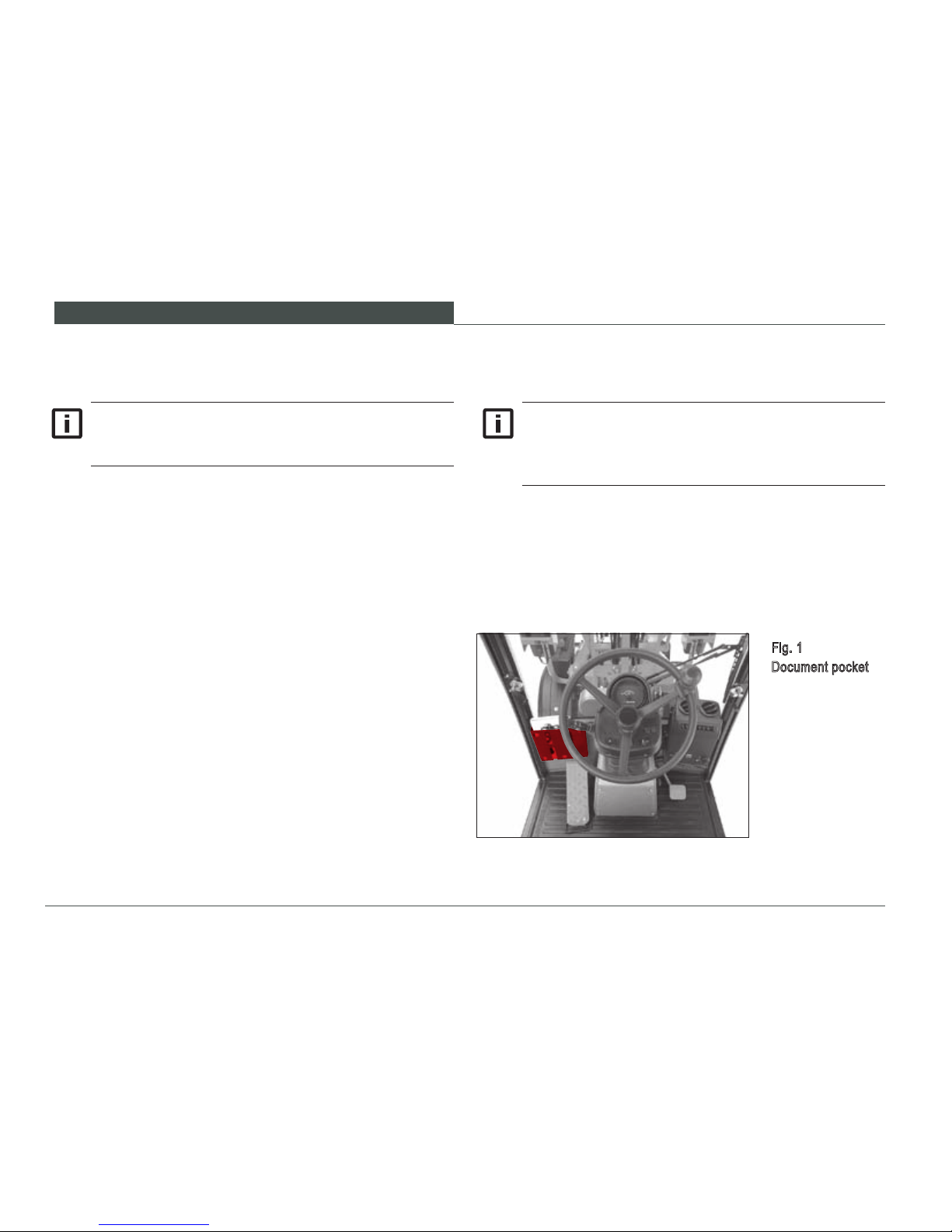
The Operator’s Manual must always be located in
the loader or at the place where it is being used.
Place the Operator’s Manual in the document pocket at the rear of the operator‘s platform.
Fig. 1
Document pocket
Page 15

B A S I C I N F O R MAT I O N
13
W L 3 0
Read and understand the operating instructions in this Manual before operating this wheel loader. Before performing
production work, the operator should nd a remote site to
become familiar with the controls and machine response.
The machine shall be in serviceable condition before attempting to use it as described in the operating instructions.
If the wheel loader is determined not to be in serviceable
condition, notify the site or machine supervisor to have it
repaired before use.
The loader is used to dislodge and load material by moving
the loader forward, taking into account the safety instructions
/ regulations and time periods listed by Wacker Neuson in
the Operator’s Manual. One work cycle consists of picking
up, lifting, transporting and unloading the material.
1.4 Intended use
The loader has been built according to applicable standards
and regulations. Operation by inexperienced persons, or in
an unintended manner, can result in hazards that can lead
to personal risk and subsequent harm to the operator and
persons in the operating area of the wheel loader. Improper
use can damage the wheel loader as well as property in the
vicinity of operation.
Unintended use can endanger the lives of operating
personnel or other persons and cause injuries or
extensive material damage.
Page 16

B A S I C I N F O R MAT I O N
14
Similar uses of the loader with alternative attachments which
do not change the safety requirements for the loader but
modify the way in which it is used are only acceptable when
attachments that have been expressly approved by Wacker
Neuson are employed. Special conditions apply if you use
optional Wacker Neuson attachments.
The intended operation is described in this Operator’s
Manual. The instructions describe how to operate, maintain, inspect and adjust the wheel loader safely. The repair
manual provides additional instruction for safely diagnosing
malfunctions and repairing the wheel loader to maintain
service and performance levels.
The wheel loader shall not be employed for any of the following work activities:
• lifting or transporting people
• using it as a working platform
• using it to lift or transport loads without providing work
equipment for it
• pulling trailer loads
•
operating after the machine has received unauthorized
repairs
• operating with unauthorized modications
Page 17

B A S I C I N F O R MAT I O N
15
W L 3 0
Page 18

B A S I C S A F E T Y I N S T R U C T I O N S
16
2 BASIC SAFETY INSTRUCTIONS
•
Use the loader and attachments only as intended and
in serviceable condition.
•
Observe the operating instructions described in this
Operator’s Manual and all applicable work site safety
regulations.
• Observe the permissible payloads.
• Wheel Loaders may only be used on suitable terrain.
This Wheel Loader is equipped with a Starter Lock
/ Drive Lock which must be kept operational.
Page 19

B A S I C S A F E T Y I N S T R U C T I O N S
17
W L 3 0
2.1 Organizational measures
The following safety instructions are directed at the operator
/ user of the loader.
•
Always keep the Operator’s Manual in the compartment
provided for it.
• As a supplement to the Operator’s Manual, universally
valid legal and other binding regulations relating to road
trafc, compulsory coverage, accident prevention and
environmental protection must be observed, and users
must be instructed to observe them. This applies in particular to the maximum speed, depending on the model
and the permissible total weight of the loader.
•
If required, instruct that personal protective equipment be
worn. This applies particularly to the handling of harmful
substances at the location of use.
•
Supplement the Operator’s Manual with instructions,
including supervisory and reporting requirements, taking
into account differences between various companies,
e.g. with regard to the organization of work, work processes or personnel used.
•
Personnel who have been assigned to operate the loader
must have read the Operator’s Manual before operating
the wheel loader especially the chapter Basic Safety
Instructions.
• Observe all safety messages on the loader and in the
Operator’s Manual.
•
Make sure that all safety messages on the machine
are legible.
•
If the loader becomes unserviceable, stop operating and
inform the supervisor that the wheel loader is not functioning normally. Alternately, contact a trained technician
to diagnose and correct the condition before resuming
operation.
•
No modications shall be made to the wheel loader.
Contact your Wacker Neuson dealer for specic advice
regarding the use of the wheel loader and approved
attachments.
Page 20

B A S I C S A F E T Y I N S T R U C T I O N S
18
• If worn or damaged parts need replacement, use only
Wacker Neuson replacement parts to ensure optimum
performance and safety.
• Inspect hydraulic hoses and ttings prior to the start of
each work shift. Correct any observed leaks or abrasion
issues before operating the machine. Extended environmental exposure can cause undetectable damage.
Replace hose assemblies periodically as advised in the
maintenance schedule.
•
Thoroughly inspect the wheel loader before each operating shift.
•
The Wheel Loader Repair Manual describes the special
tools, diagnosis techniques, repair sequence procedures, lifting and supporting devices needed to repair this
machine. To avoid unnecessary hazards and possible
damage to the Wheel Loader, do not attempt to repair
this machine without complying with the instructions in
the Repair Manual.
•
Make the location and means of operation of the re
extinguishers known, and consider the options for re
detection and ghting.
•
A Falling Object Protection System (FOPS) is available
for the Wheel Loader Operator Protection System. OSHA
and MSHA require this protection when operating with
overhead hazards. Contact your Wacker Neuson dealer
for advice and availability of a certied FOPS.
Page 21

B A S I C S A F E T Y I N S T R U C T I O N S
19
W L 3 0
2.2 Selection and qualication of personnel / basic duties
•
Personnel being trained, educated, instructed or participating in a general training program may only work on
or with the machine under constant supervision of an
experienced, authorized supervisor.
•
Work on the machine‘s electrical equipment may only
be perform by an electrician or by trained persons under
the direction and supervision of an electrician.
• Work on the chassis, brakes and steering system may
only be performed by trained, specialized personnel.
•
Only trained, specialized personnel with specic knowl-
edge of and experience in hydraulics may work on hydraulic units.
•
The operator of the wheel loader must be qualied to
operate the machine through demonstration of comprehension of the operating instructions. No one shall
operate the wheel loader if impaired due to intoxication
or drug reaction.
•
Diagnosis and repair of the wheel loader shall be performed by trained competent technicians unimpaired by
intoxication or drug reaction.
•
Prohibit unauthorized and untrained people from access
to the starting key and operation of the wheel loader.
•
The wheel loader operator is responsible for visually
monitoring the work area of the wheel loader and preventing anyone from entering the area without permission. If a person enters the area while the wheel loader
is in operation, the operator shall stop the wheel loader
and instruct the person to leave the work area until the
wheel loader has been stopped in a safe mode. The
person may then approach the machine in full view of
the operator.
Page 22

B A S I C S A F E T Y I N S T R U C T I O N S
20
2.3 Safety instructions for certain operating phases
•
If the wheel loader does not respond as expected to the
operator command or exhibits a malfunction, stop the
machine, contact the supervisor and restore the machine
to serviceable condition before resuming operation.
•
Start and operate the loader only from the operator’s
seat.
•
When switching on and off, observe the indicator displays in accordance with the Operator’s Manual.
•
Make sure no one is located in the operating area of the
loader before starting the engine.
•
After starting the engine and conrming that the indi-
cators are responding correctly, activate the steering,
brakes, lights, signals and loader/accessory functions
to conrm that these devices are responding correctly
to the control command.
•
To avoid damage to the wheel loader, position the loader
bucket or accessories before moving the machine. Re-
conrm that there are no people in the work or travel
area before moving the machine.
The safety instructions are directed at all persons involved
in work on or with the loader.
2.3.1 Safety instructions for normal operation
•
Refrain from any measures that could put safety into
question.
•
Before starting work, familiarize yourself with the working
environment in which you will be using the loader. The
working environment includes, for example, obstacles in
the working and trafc area, the bearing capacity of the
ground and the necessary safeguarding of the location
to allow it to be used as a public trafc area.
• Take precautions to ensure that the loader is operated
only in a safe, serviceable state.
•
Only operate the loader if all the protection devices and
safety devices, e.g. detachable protection devices, sound
absorbers and exhaust equipment, are serviceable and
operational.
•
Check the loader at least once a day for visible defects.
Page 23

B A S I C S A F E T Y I N S T R U C T I O N S
21
W L 3 0
•
When driving on public roads, lanes and squares, ob-
serve the valid road trafc regulations and put the loader
into a condition permissible for the road beforehand.
•
As a matter of principle, turn on the lights when traveling
on public roads to increase awareness for road trafc..
•
When driving through underpasses, gates, bridges, tunnels, overhead lines, etc., always make sure that you
have enough clearance above and on both sides and a
sufcient safety margin.
•
Always keep sufcient distance away from excavations,
embankments and the edges of piled up material.
•
Refrain from any method of operation that could adversely affect the loader‘s stability. This also includes
the duty to pass on information regarding the approved
carrying capacity (=payload) for the relevant loader at-
tachments. (carrying capacity / approved payload are
specied in the Operator’s Manual)
• Do not drive transversely on slopes; always keep work
equipment and load near the ground, especially when
driving down slopes.
•
When driving down a slope, always adjust your driving speed to take account of the respective conditions.
Always reduce your speed before reaching a downhill
slope, and not after you have reached it.
•
The load must be located on the uphill side during driving on downhill or uphill slopes.
• As a matter of principle, always secure the loader from
accidentally rolling away and against unauthorized use.
Turn off the engine, put on the parking brake, lower the
work equipment, remove the starting key and, if necessary, employ a wheel chock.
Page 24

B A S I C S A F E T Y I N S T R U C T I O N S
22
2.3.2 Safety instructions for other operating modes
These safety instructions refer to special tasks relating to the
use of the loader and servicing tasks - as well as emergency
maintenance during operation or work concerning disposal
of the auxiliary and operating materials.
•
The Operator’s Manual provides adjustment, maintenance and inspection information and schedules in
subsequent sections. This information is essential to
ensuring peak performance satisfaction and safety over
the life of the wheel loader.
•
This Operator’s Manual provides routine adjustment
and maintenance procedures in addition to operating
instructions. Diagnosis and repair of the wheel loader
requires special skill, training and tools. Your Wacker
Neuson dealer has the trained technicians to perform
such work safely and effectively.
•
Maintenance and repair work shall be performed by
operators and technicians trained and knowledgeable
of the wheel loader function and attachments.
•
Do not attempt to perform maintenance or repair on the
wheel loader until the machine and engine is stopped
and all attachments are in a stable position. Do not attempt to perform maintenance or repair work on hot
surfaces or components of the machine. Read and understand the procedure for maintenance and repair in
the Operator’s and Repair Manuals for this wheel loader.
•
Secure the maintenance area, allowing as large a space
as required.
•
If the loader is being completely shut off during servicing
and maintenance work, please observe the following
(see the chapter »Securing the Loader«):
- Secure the loader from being accidentally turned back
on by removing the starting key.
- Attach a warning note to indicate that the loader is be-
ing worked on.
-
Only perform servicing and maintenance work if the
loader is parked on an even, hard surface and secured
from rolling away and articulating at the steering swivel
point..
-
Before performing work with the loader arms raised,
install the support provided to prevent the loader arms
from lowering suddenly and inadvertently.
- This device shall conform to ISO 10533.
Page 25

B A S I C S A F E T Y I N S T R U C T I O N S
23
W L 3 0
•
Use lifting devices to raise and support parts and assemblies exceeding 10 kg (22 lbs) weight during repair
and replacement activity. Use only OSHA approved
devices to perform the lifting operation and verify that
the lifting devices are in serviceable condition.
• The use of a crane to lift heavy assemblies or compo-
nents requires that the operator is certied by OSHA.
The person attaching the load and signaling the operator
must be trained in proper techniques as well as voice
and hand signals to instruct the crane operator.
•
For assembly above head height, use only climbing aids
and working platforms which are intended for this purpose, or which are safe for use in this situation. Do not
use machine parts as climbing aids. Keep all handles,
steps, pedestals, platforms and ladders free of dirt, snow
and ice.
•
Clean the entire loader, especially the connections
and threaded connections, with oil, fuel or care products when beginning maintenance and servicing work.
Use lint-free cleaning rags and no aggressive cleaning
agents.
•
Before cleaning the loader with water or by steam jet
(high-pressure cleaner) or with other cleaning agents,
cover up / seal off all the openings into which water,
steam and cleaning agents are not permitted to enter.
Electrical components, inlets and outlets for the engine‘s
combustion air and reservoir openings are particularly
at risk. Completely remove the covers / seals after you
have nished cleaning.
•
Before restarting, retighten any threaded connections
loosened during servicing and repairs, in particular for oil
or fuel lines. When performing maintenance and servicing work, check all the lines and threaded connections
for leaks and tight t.
Page 26

B A S I C S A F E T Y I N S T R U C T I O N S
24
•
Should it be necessary to remove safety devices during
setup, servicing or repairs, reinstall and check the safety
devices immediately after nishing the work and verify
that the devices perform correctly.
•
Replace the ROPS (Roll Over Protective Structure) or
FOPS structure if it is permanently deected, a member
is deformed, it has become corroded, and/or it has been
modied. If the mounting structure, base, or mounting
hardware is damaged, consult your Wacker Neuson
dealer for assistance. Do not attempt to repair, straighten
or reuse a damaged ROPS or FOPS.
•
Responsibly dispose of the unwanted materials and
uids resulting from the repair. Hazardous material shall
be disposed in a hazardous material container(s). Parts
and assemblies can be recycled.
WARNING
Never use the machine without the ROPS/FOPS
properly installed.
►
Do not drill, weld, straighten, or bend the ROPS
/ FOPS protective structures.
►
Allow only trained authorized personnel to install
new ROPS / FOPS structures.
ROPS / FOPS - protective structures
Page 27
B A S I C S A F E T Y I N S T R U C T I O N S
25
W L 3 0
2.4 Safety instructions for particular hazards
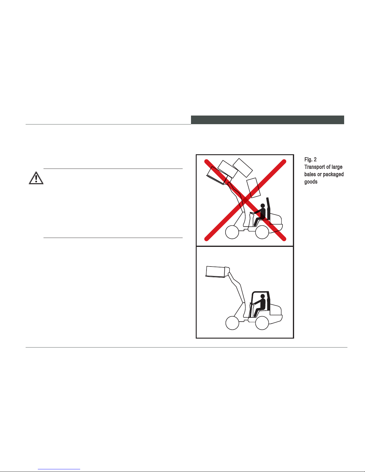
2.4.1 Forklift attachment
WARNING
Personal injury hazard.
Falling objects can strike the operator.
►
Do not transport large bales or packaged goods
without a FOPS (operator canopy or cabin).
►
Ensure that large loads are properly secured
and supported. See ANSI B56.1, OSHA1910 and
OSHA1926 for regulations on carrying material.
► Do not stack load higher than fork restraint.
Fig. 2
Transport of large
bales or packaged
goods
Page 28

B A S I C S A F E T Y I N S T R U C T I O N S
26
WARNING
Electric shock hazard.
The operator of the Wheel Loader can be killed if
the Wheel Loader comes in contact with electrical
wires.
► Keep the loader and attachment tools at a suf-
cient distance from overhead power lines and
other electrical lines of more than 50 V (see
table below).
If inadvertent contact with a live electric source occurs:
•
Do not leave the loader until the electricity has been
disconnected and a qualied technician directs the operator to leave the machine..
• If feasible, drive the loader away from the danger area!
•
Warn any people around the loader not to get any nearer
and not to touch the machine.
• Arrange to have the power turned off.
2.4.2 Working near overhead power lines
Nominal voltage Clearance distance
up to 1000 V 1 m 3.3 ft
over 1 kV up to 110 kV 3 m 9.8 ft
over 110 kV up to 220 kV 4 m 13 ft
over 220 kV up to 380 kV 5 m 16.4 ft
Unknown nominal voltage 5 m 16.4 ft
Page 29

B A S I C S A F E T Y I N S T R U C T I O N S
27
W L 3 0
2.4.3 Electrical power
• Regularly check the loader‘s electrical equipment. Defects, such as loose plug connections or cables with
burnt insulation, shall be replaced before resuming operation.
•
If an electrical malfunction is discovered, stop the wheel
loader in a safe location, lower the loader arms and attachment to the ground and stop the engine. Contact
the supervisor for diagnosis and repair by a qualied
technician before resuming operation.
•
Replacement fuses shall be of the same type and capac-
ity as specied by the manufacturer in the Operator’s
and Repair Manuals. Do not attempt to bypass a fused
system to resume operation.
2.4.4 Flying sparks / re danger
WARNING
Fire hazard.
Sparks from the exhaust, or electrical equipment, or
hot machine parts can ignite explosions and res.
►
Do not work in enclosed spaces where am-
mable materials, explosive vapors, or combustible dust are found.
► Stay clear of ammable materials such as hay
and straw.
►
Park the Wheel Loader only in areas free of
ammable materials.
Page 30

B A S I C S A F E T Y I N S T R U C T I O N S
28
2.4.5 Gas, dust, steam, smoke
•
Diesel engine exhaust emissions are toxic in concentrated amounts. Do not operate the wheel loader in enclosed spaces or inadequately ventilated spaces.
•
Determine and follow regulations regarding safe opera-
tion at the specic work site.
- Do not operate the wheel loader near open ames.
-
Do not perform welding repairs in explosive atmospheres.
-
Do not weld fuel reservoirs or fuel system components.
- Do not perform any welding operation unless qualied
to do so.
•
Wear appropriate personal protective equipment (breath-
ing lter, protective suit) for protection against specic
dangers, e.g. poisonous gases, corrosive steam, poisonous (i.e. containing toxins) surroundings, etc.
2.4.6 Hydraulics, pneumatics
• When detected, oil leaks shall be repaired to avoid:
- environmental hazards
- re hazards
- slip hazards
- explosion hazards
- personal injury hazards.
•
Do not attempt to repair a hydraulic system or component
until the hydraulic pressure has been relieved. Relieve
the pressure by activating controls as advised in this
Operator’s Manual or the Repair Manual.
• Replace hydraulic lines and ttings with original equipment parts from your Wacker Neuson dealer to assure
original performance and safety. The reinstalled hydraulic line routing and attachment shall conform to the
original routing. Conrm that the replacement routing
is not interfering with other parts, chang across sharp
surfaces or resting on or near hot surfaces.
Page 31

B A S I C S A F E T Y I N S T R U C T I O N S
29
W L 3 0
NOTICE
Use the appropriate fuel for climate temperature
ranges to avoid engine stoppage from fuel gelling.
2.4.8 Noise
•
All the loader‘s sound-proong devices must be in their
protection position during operation.
• If necessary, the operator must wear personal hearing
protection.
2.4.9 Oils, grease and other chemical substances
• Observe the valid safety regulations for the respective
product when handling oil, grease and other chemical
substances.
• Do not service the wheel loader immediately after op-
eration. Wait until hot surfaces have cooled and can be
touched comfortably.
•
Smoking and open ames are prohibited during fueling.
Danger of re or explosion!
2.4.7 Tip-overs
WARNING
Personal injury hazard.
Falling Loader can strike or crush the operator.
►
Do not operate the wheel loader without fastening the seat belt.
►
Keep the loader lift arms and attachment as low
as practical when traveling.
If the machine tips over, or in the event of an extreme slope condition, take the following steps to
avoid engine damage:
►
Stop the engine as quickly as practical to avoid
damage from lubrication starvation.
► Do not operate the engine or machine after an
incident until a technician has inspected and corrected any damage resulting from the incident.
Page 32

B A S I C S A F E T Y I N S T R U C T I O N S
30
2.5 Transporting and towing / restarting
• Instructions are provided in this Operator’s Manual for
towing, loading and transporting the wheel loader safely
without machine damage.
•
The towing machine shall be capable of towing the wheel
loader.
•
The loading and transport equipment shall be appropriate to safely complete the sequence of operation. If the
wheel loader is to be lifted by a crane device, consult
the machine specications to select the correct crane
capacity and OSHA lifting devices to safely complete
the lifting operation.
•
Only restart the loader according to the Operator’s
Manual.
•
See Chapter 6 for complete transporting and towing
instructions.
2.6 Final decommissioning / dismantling
•
Drain and dispose of all uids in suitable containers and
dispose of the uids in an environmentally responsible
manner. Do not dispose in sewers, streams, lakes or
on the ground.
• Remove the battery and dispose of it at an authorized
recycling center. Remove the starting motor to disable
the engine.
•
Dismantle and recycle the components according to the
material instructions on the individual parts. Tires and
rubber based parts can be recycled separately.
Page 33

B A S I C S A F E T Y I N S T R U C T I O N S
31
W L 3 0
1
5
311
15
6
8 9
10
2
14
7
12
13
Fig. 3
Location of the
Safety labels
2.7 Safety labels used
Maintain all safety message labels on the machine
in a legible manner. If a safety label becomes damaged or illegible, replace it with a new label available from your Wacker Neuson dealer or at www.
wackerneuson.com.
Page 34

B A S I C S A F E T Y I N S T R U C T I O N S
32
Safety label 3
Warning
Personal injury hazard from falling
equipment.
Never stand in the unsecured danger
area.
Use the safety supports.
Safety label 1
Warning
Do not stand near the loader during
operation.
Do not go under the loader lift arms
when raised.
Safety label 2
Shearing hazard
Shearing hazard from rotating fan. Stop
the engine before entering the area.
Safety label 4
Warning
Personal injury hazard. The rollover bar
should always be locked in protection
position, insofar as this is possible given
the working conditions.
Page 35

B A S I C S A F E T Y I N S T R U C T I O N S
33
W L 3 0
Safety label 5
Important
Remove the starting key and read the
Repair Manual before proceeding with
any work activity on the wheel loader.
Safety label 6
Important
Lubricate the center joint daily before
beginning work. Refer to your Operator’s Manual for more information.
Safety label 7
Warning
Hot surfaces can cause burns.
Do not touch hot surfaces.
Safety label 8
Warning
Never lift or transport people with the
lifting attachment.
Page 36

B A S I C S A F E T Y I N S T R U C T I O N S
34
Safety label 12
Warning
Personal injury hazard. The Wheel
Loader can injure people on the work
site who are in the danger zone.
Keep personnel away from the Wheel
Loader during operation!
Safety label 11
Warning
Pinching/crushing hazard. Avoid the articulation area while the Wheel Loader
is in operation. Before working in the
articulation area and before transporting, secure the articulation pivot. Refer
to Operator’s Manual.
Safety label 10
Warning
Personal injury hazard.
Never transport passengers on the
Wheel Loader.
Safety label 9
Warning
Personal injury hazard. Always wear
the seat belt while operating the wheel
loader.
Page 37

B A S I C S A F E T Y I N S T R U C T I O N S
35
W L 3 0
Safety label 14
Warning
Safety label 13
Warning
15 PSI
1 BAR
If the ROPS / FOPS protective structures are damaged,
they can not serve their protective function.
Never drill or weld the ROPS / FOPS protective structures.
Refer to Operator’s Manual.
Hot liquids or steam escaping
under pressure can cause burns.
Do not open radiator when it is hot. Re-
fer to Operator’s Manual.
Label 15
Possibility of equipment
damage
Close both doors before tilting the cab.
Page 38

B A S I C S A F E T Y I N S T R U C T I O N S
36
2.8 Safety devices
2.8.1 Fire extinguisher Fig. 4
Fire extinguisher
Fig. 5
Attaching the rotating beacon
The receptacle for the rotating beacon can be attached to
the operator cab roof in the back (Fig. 5).
To switch the rotating beacon on and off, see the chapter
»Switches / rocker switches«.
Use the yellow rotating beacon according to local
regulations.
Contact your Wacker Neuson dealer if you want
to install a re extinguisher or a rotating beacon.
Your Wacker Neuson dealer has the trained technicians to perform such work safely and effectively.
A re extinguisher can be installed to operator cab rail to
the right of the operator ‘s seat. (Fig. 4).
2.8.2 Rotating beacon (Optional equipment)
Page 39

B A S I C S A F E T Y I N S T R U C T I O N S
37
W L 3 0
2.8.3 Seat belt
Before starting the engine:
•
adjust the seat to provide comfortable access
to all control ranges.
•
examine the seat belt webbing for any mechanical or chemical damage and replace if necessary.
•
inspect all seat belt hardware for functionality and serviceability, repairing or replacing if
necessary.
•
fasten the seat belt and adjust to contact the
lower torso rmly.
When not in use:
• store the seat belt by placing it across the seat
pad.
•
ensure that the seat belt retractors work freely.
2.8.4 Backup alarm for reverse drive
(Optional equipment)
A backup alarm sounds when reverse gear is engaged.
The sound is to warn persons who are in the vicinity of the
loader that the loader is going into reverse.
Fig. 6
Seat belt
Page 40

B A S I C S A F E T Y I N S T R U C T I O N S
38
2.8.5 Emergency exit
Fig. 7
Emergency exitThe cab door on the left side of the machine fac-
ing the forward direction of travel is the primary
access system to the operator station. The right
hand access is a secondary opening intended for
emergency use only.
Page 41

B A S I C S A F E T Y I N S T R U C T I O N S
39
W L 3 0
2.8.6 Battery disconnect switch
Disconnect the battery from the electrical system by rotating
the key counter-clockwise. In an emergency, the disconnect switch can be used to disconnect the battery from
the electrical system. Disconnecting the battery from the
electrical system will reduce the possibility of discharge
before the next use. Also, disconnecting the battery from
the electrical system and removing the key is a means of
resisting machine theft.
• Turn the switch lever counter-clockwise:
– The battery is disconnected from the electrical system
• Turn the switch lever clockwise:
– The battery is connected to the electrical system.
After removing the disconnect switch key, place the
attached cover over the key opening to prevent dirt
and water from entering the switch.
To connect the battery to the electrical system,
remove the cover, insert the key and rotate the key
clockwise. To avoid inadvertent control behavior,
do not disconnect the battery from the electrical
system with the engine running or any electrical
systems activated.
Fig. 8
Battery disconnect
switch
Page 42

B A S I C S A F E T Y I N S T R U C T I O N S
40
2.8.7 Loader lift arm locking system
Apply the locking system for the loader lift arm by shifting
the lever located to the right of the operator’s seat Item 1
(Fig. 9).
•
Push the switching control rearward toward the seat
frame:
– the locking system is now on.
•
Pull the switching control forward away from the seat
frame:
– the locking system is now off.
CAUTION
Possibility of inadvertent loader lift arm activation.
Inadvertent activation can result in the loader arms
dropping causing the bucket or attachment to engage the road surface. This can result in loss of
machine control with possible injury to the operator
and other work site persons.
►
Always lock the loader lift arm control to prevent
inadvertent activation during travel.
► The operator shall not leave the operator seat
until the loader arms and attachment have been
lowered to and are resting on the ground.
The loader lift arm can be secured against unintentional operation by means of a locking mechanism.
If you have switched on the locking mechanism, the
loader lift arms will not move if the loader controls
are moved. The fact that the loader lift arm is locked
is not shown via indicator lights, but instead can be
seen from the position of the switching lever (Fig. 9).
Fig. 9
Lever for the locking
mechanism of the
Loader lift arm
1
Page 43

TE CH N IC A L D ATA
41
W L 3 0
3 TECHNICAL DATA
3.1 Technical description
The loader consists of the vehicle frame, the drive and the
axles. The vehicle frame contains all the drive and control
units for the standard conguration. The vehicle frame consists of the front carriage with the loader lift arms, and the
rear carriage, in which the drive unit is situated. They are
connected by an articulated swivel joint.
Drive
The loader is driven by a diesel engine, which powers the
steering and working hydraulics and the driving hydraulics.
The propulsion hydraulics provide power to the transfer
gear box by a directly attached hydraulic motor. The rear
axle is integral with the transfer gear box. The front axle is
powered by a driveshaft connecting the transfer gear box
to the front axle.
The axles are designed as rigid axles.
Brakes
Service braking is provided by the propulsion hydraulic
system through the transfer gearbox and driveshaft to both
axles. The braking-inching pedal provides a secondary service brake by contacting a hub-mounted differential in the
transfer gear box. A separate parking brake with separate
control is provided that engages the differential hub in the
transfer gear box.
Steering
The fully hydraulic articulated swivel steering system operates via a dual action cylinder.
Page 44

TE CH N IC A L D ATA
42
Hydraulics
The loader has two hydraulic systems supplied by a hy-
draulic uid reservoir:
- hydrostatic drive
- steering and working hydraulics
The hydrostatic drive consists of an axial piston variable
displacement pump, which drives an axial piston motor. The
axial piston variable displacement pump is rigid coupled
directly to the diesel engine, while the axial piston motor is
directly coupled to the transfer case.
Displacement is automatic and continuous, but depends on
speed and load. The travel speed depends on the engine
speed and the machine load. Operating speed is set by
the accelerator pedal position, engine speed and torque
demand of the loading operation. Depending on load, the
variable displacement pump automatically adjusts pump
displacement to balance torque and speed requirements
within the power capability of the diesel engine. Since the
input power is limited to the diesel engine output, increased
demands from traversing a grade or loading the bucket will
result in speed reduction which increases the torque to meet
the performance demand. This adjustment control allows
the entire range of performance to be utilized optimally.
Actuating the inching pedal is an override control that can
reduce wheel loader speed as operation demands. Depressing the pedal to the full range will stop the travel motion
of the wheel loader. The inching pedal permits an innite
number of control positions. The inching pedal provides the
service brake function by destroking the pump until no uid
is transmitted between the pump and motor.
A gear hydraulic pump supplies the steering and working
hydraulics with oil. The gear pump is rigid coupled to the
drive‘s variable displacement pump. Pump ow output is
directly proportional to the diesel engine speed.
The hydraulic system is equipped with relief valves, lters
and oil coolers.
Page 45

TE CH N IC A L D ATA
43
W L 3 0
Electrical system
The electrical system operates at 12 volts and the electrical
circuits are protected by fuses to prevent overload damage
to the system and its components.
Equipment
The loading equipment consists of the loader lift arms with
an integrated mechanical or hydraulic quick-change receptacle, lifting and tipping cylinders and the appropriate
attachments.
The loader is equipped with a rollover protective structure
(ROPS).
3.2 Loader data
Engine
4-cylinder Perkins diesel engine
Output
35.7 kW / 49 hp at 2600 rpm
SAE rating according to ISO9249
Type 404 D – 22 water-cooled
Capacity 2216 cm³ (135 inch³)
Dr ive (driving speed)
1. gear
0 – 7 km/h
0 – 4.35 mph
2. gear
0 – 20 km/h
0 – 12.43 mph
Steer ing
Fully hydraulic center-pivot steering
Rotating angle 12°
Turn angle 45°
Elect rical system
Working voltage 12 volts
Battery 77 Ah
Page 46

TE CH N IC A L D ATA
44
Weight spec ifications
Operating weight 3120 kg 6878 lb
Permissible total weight 3400 kg 7496 lb
Permissible axle load per axle 2500 kg 5512 lb
Permissible payload with shovel 828 kg 1825 lb
Permissible payload with pallet fork 798 kg 1759 lb
Hydraulics
Driving hydraulics
Flow rate 78 l/min 20.61 gallons/min
Working pressure 450 bar 6527 psi
Working hydraulics
Flow rate 49 l/min 12.94 gallons/min
Working pressure 210 bar 3046 psi
Steering hydraulics
Flow rate 49 l/min 12.94 gallons/min
Working pressure 190 bar 2756 psi
Noise values
Average LwA measured at the operator‘s ear 98.4 dB(A)
Guaranteed LwA measured at the operator‘s
ear
100 dB(A)
Specied LpA measured at the operator‘s ear 80 dB(A)
Vibrations (weighted effective value)
Upper extremities no more than 2.50 m/s² 8.19 ft/s²
Feet or seat surface no more than 0.80 m/s² 2.64 ft /s²
Page 47

TE CH N IC A L D ATA
45
W L 3 0
1
3.3 Product identication number plates
A product identication number plate is attached to the
loader on the right side of the front carriage (Fig. 10).
It lists the following information:
• Manufacturer
• Vehicle ID
• Type
• Engine power
• Axle loads
• Operating weight
• Permissible total weight
In addition, the vehicle ID is engraved on the right side of
the rear end near the entry area (Fig. 10/1).
Furthermore, the following loader components each have
their own rating plate:
• The diesel engine
•
The axial piston variable displacement pump (hydraulic
transmission pump)
• The oil engines (hydraulic traction motor)
• The axles.
Fig. 10
Vehicle ID
Wacker Neuso n SE
Preußenstraße 41
80809 M unich/Ge rmany
Fahrzeug-Ident-Nr.
Betriebsgewicht kg zul. Achslast hinten kg
zul. Ges Gew. kg
Hom.-Nr
zul. Anhängelast kg
Art.-Nr.
Motorleistung kW
zul. Achslast vorn kg
Radlader
Made by Weidemann / Flechtorf Germany
Typ
Page 48

TE CH N IC A L D ATA
46
3.4 Dimensions
Fig. 11 Dimensions
Page 49

TE CH N IC A L D ATA
47
W L 3 0
*In the event of deviating tires or reversed wheel rims the dimensions will change
Dimensions with 31x15,5-15EM tires
Item Designation Value
A Overall length with standard
shovel
4554 mm 179.29 inch
A‘ Overall length without shovel 3748 mm 147.56 inch
B Axle center to shovel pivot-
point
722 mm 28.43 inch
C Wheelbase 1732 mm 68.19 inch
D Rear overhang 1179 mm 46.42 inch
E Overhead loading height* 2990 mm 117.72 inch
F Max. height of shovel pivot
point*
3209 mm 126.33 inch
G Height of seat* 1254 mm 49.37 inch
H Max. dumping height* 2416 mm 95.12 inch
I Scraping depth* 26 mm 1.02 inch
K Reach at H* 334 mm 13.15 inch
L Height to top of cab* 2251 mm 88.62 inch
Item Designation Value
M Total working height* 4070 mm 160.24 inch
N Max. dumping angle at max.
lift height
43°
O Reverse roll angle on ground 43°
P Reverse roll angle at max. lift 50°
Q Inside turning radius* 1413 mm 55.63 inch
R Overall width* 1345 mm 52.95 inch
S Radius at outer edge* 2793 mm 109.96 inch
T Ground clearance* 261 mm 10.28 inch
U Turn angle 45°
V Width across cab 870 mm 34.25 inch
W Track width* 941 mm 37.05 inch
Z Maximum turning radius
(depends on shovel width)
3186 mm 125.43 inch
Page 50

DE SCR I PT ION O F T HE I NDI CATO R , WA R NI NG A ND CO N TR OL EL E ME NTS
48
4 DESCRIPTION OF THE INDICATOR, WARNING AND CONTROL ELEMENTS
4.1 Operating elements and instruments
Fig. 12
Operating elements
1
2
3
4
5
6
7
8
9
10
11
Page 51

DE SCR I PT ION O F T HE I NDI CATO R , WA R NI NG A ND CO N TR OL EL E ME NTS
49
W L 3 0
Item Designation
1
Steering wheel turning knob
2
Instrument panel
3
Steering wheel
4 Accelerator
5
Operating lever for load arm / drive
6
Operating lever for optional hydraulics
7
Operating lever for parking brake
8
Operator’s seat
9
Braking-inching pedal
10
Operating lever for adjusting the steering column
11
Operating lever for lighting, turn signals and signal horn
Page 52

DE SCR I PT ION O F T HE I NDI CATO R , WA R NI NG A ND CO N TR OL EL E ME NTS
50
4.2 Control and warning indicator lights
• If the indicator lights do not illuminate properly
at the starting sequence, repair the malfunction
before operating the machine.
•
If an indicator light illuminates during operation,
move the machine to a safe place, lower the
loader arms and stop the engine.
•
Do not operate the wheel loader until the reason
for the illuminated indicator is determined and
corrective action has been completed.
Immediately turn off the engine if a light marked with
this * symbol is illuminated in the adjacent table.
Fig. 13 Control and warning lights
123467895
Page 53

DE SCR I PT ION O F T HE I NDI CATO R , WA R NI NG A ND CO N TR OL EL E ME NTS
51
W L 3 0
Item Designation Function Symbol
1 Not used No function
2 Heater indicator light Illuminates during preheating
3 Not used No function
4 * Warning light for engine oil pressure Illuminates when engine oil pressure is too low
5 * Warning light for generator Illuminates if the battery is not charged
6 * Warning light for engine temperature Illuminates when engine temperature
7 Indicator light for for ward drive Illuminates when gear is set to forward drive
8 Indicator light for reverse drive Illuminates when gear is set to reverse drive
9 Indicator light for crawler gear Illuminates when crawler gear is engaged
Page 54

DE SCR I PT ION O F T HE I NDI CATO R , WA R NI NG A ND CO N TR OL EL E ME NTS
52
• If the indicator lights do not illuminate properly
at the starting sequence, repair the malfunction
before operating the machine.
•
If an indicator light illuminates during operation,
move the machine to a safe place, lower the
loader arms and stop the engine.
•
Do not operate the wheel loader until the reason
for the illuminated indicator is determined and
corrective action has been completed.
Immediately turn off the engine if a light marked with
this * symbol is illuminated in the adjacent table.
Control and warning indicator lights
Fig. 13 Control and warning lights
101112131516171814
Page 55

DE SCR I PT ION O F T HE I NDI CATO R , WA R NI NG A ND CO N TR OL EL E ME NTS
53
W L 3 0
Item Designation Function Symbol
10 Indicator light for parking brake Illuminates when the parking brake is on
11 Not used No function
12
Indicator light for main beam Illuminates when the main beam is switched on
13 Not used No function
14
Air lter indicator light Illuminates when the air lter is contaminated
15 Turn signal indicator light Illuminates when a turn signal is on
16 Warning light for return lter Illuminates if the pressure at the return lter is too high
17 * Warning light for hydraulic oil temperature Illuminates when hydraulic oil temperature is too high
18 Indicator light for overdrive Illuminates when overdrive is engaged
Page 56

DE SCR I PT ION O F T HE I NDI CATO R , WA R NI NG A ND CO N TR OL EL E ME NTS
54
4.3 Switches / rocker switches
Fig. 14 Switches / rocker switches (1)
1 2 3 4 5 6 7 8
Page 57

DE SCR I PT ION O F T HE I NDI CATO R , WA R NI NG A ND CO N TR OL EL E ME NTS
55
W L 3 0
Item Designation Function Symbol
1 Combination switch Switches lighting and signal horn on/off
2
No function
Available for optional equipment
Switches the optional hydraulics in order to release the
hydraulic locking device for attachments
3 Rocker switch for hazard warning lights Switches hazard warning lights on/off
4 No function
Available for optional equipment
Switches electrical connector on the lift arms on/off
5 No function Available for optional equipment
6
No function Available for optional equipment
7
No function Available for optional equipment
8 Engine starting switch For switching the engine on/off
Page 58

DE SCR I PT ION O F T HE I NDI CATO R , WA R NI NG A ND CO N TR OL EL E ME NTS
56
9 10 11 12 13 14
Switches / rocker switches
Fig. 15
Switches / rocker
switches (2)
Page 59

DE SCR I PT ION O F T HE I NDI CATO R , WA R NI NG A ND CO N TR OL EL E ME NTS
57
W L 3 0
Item Designation Function Symbol
9 Rocker switch for front windshield wipers Switches front windshield wipers on/off
10 Rocker switch for rear windshield wipers Switches rear windshield wipers on/off
11 Rocker switch for front headlights Switches front headlights on/off
12 Rocker switch for rear headlights Switches rear headlights on/off
13 Rocker switch for rotating beacon Switches rotating beacon on/off
14 No function Available for optional equipment
Page 60

DE SCR I PT ION O F T HE I NDI CATO R , WA R NI NG A ND CO N TR OL EL E ME NTS
58
4.4 Indicator devices
Fig. 16 Indicator devices
2 431
Item Designation Function Symbol
1 Fuel gauge Shows the fuel quantity
2 Tachometer Shows the diesel engine‘s rpm
3 Hour meter
Adds up the loader‘s operating
time. Plan your service work
and inspection work according
to the meter reading
4
Engine temperature
Shows the diesel engine‘s
temperature
Page 61

DE SCR I PT ION O F T HE I NDI CATO R , WA R NI NG A ND CO N TR OL EL E ME NTS
59
W L 3 0
Page 62

O P E R A T I N G A ND O PE R A T I O N
60
5 OPERATING AND OPERATION
5.1 Before starting up 5.1.1 Fueling
Read the Operator’s Manual before starting up the
loader.
•
Only operate the loader from the operator’s seat.
• Observe OSHA safety regulations.
•
Arrange for training with an experienced operator. Practice operating the wheel loader in a
remote at area to become familiar with control
response.
•
Using this Manual as a reference, conduct an
inspection before operating the wheel loader.
•
After prolonged storage or inactivity, refer to the
procedure for preparing to operate the loader.
•
Lower the loader lift arms and attachment to the
ground and stop the engine to fuel the loader.
•
Fire hazard – diesel fuel is ammable! Do not
smoke and avoid re and open ames when
fueling.
•
Do not use gasoline. Use only diesel fuel. Do
not add gasoline to diesel fuel.
•
Diesel fuel is hazardous to your health. Wear
appropriate gloves.
•
If an inadvertent incident occurs during fueling, take immediate appropriate measures to
avoid hazards. Inform the supervisor or person
responsible for the fueling operation.
Page 63

O P E R A T I N G A ND O PE R A T I O N
61
W L 3 0
The diesel reservoir is located in the front frame of the
loader. The reservoir‘s ller neck is located on the right side
of the front frame (Fig. 17).
• Unscrew the cap from the ller neck.
• Fuel the loader‘s reservoir through the ller neck.
•
Carefully replace the fuel cap on the ller neck after
fuelling.
NOTICE
Use only clean, conventional high-grade diesel fuel
to operate the loader.
If at all possible, use a ne lter in the lling line.
ENVIRONMENTAL NOTE
Diesel fuel is hazardous to the environment.
Do not allow it to be released uncontrollably into
the environment.
Immediately soak up with binding material any fuel
that has leaked, overowed or been spilled, and
dispose of it in an ecologically sound manner.
Immediately inform the persons responsible if fuel
has been released into the environment.
Fig. 17
Fuel filler neck
L O W SU L F UR F UE L
O R U LT RA
L O W
S U L FU R
F U EL O N LY
3 9 0 1 9 9 3 9 0
Page 64

O P E R A T I N G A ND O PE R A T I O N
62
Before entering the cab
• Check that the loader is clean and undamaged.
•
Check that the handles and steps are in good condition
and clean.
• Check that the cab windows are in good condition and
clean.
• Check that all safety components are present and fully
functional.
• Check that the rods, cylinders, hinge pins and coolers
are clean.
•
Check that all the fasteners, joints and hinge pins t
tightly.
•
Check that all the safety messages and instructional
labels are present and in good condition.
• Check the loader for oil, fuel and coolant leaks.
5.1.2 Operation
WARNING
Personal injury hazard.
► Do not operate the loader if it is not in service-
able condition or responding correctly to control
commands.
►
Park the machine in a safe place, lower the
loader arms and attachment, stop the engine
and notify your supervisor.
►
Do not operate the machine until the problem
has been corrected.
► Check that the safety devices are present and
operative each time before you start up the
loader.
►
Replace damaged tires to avoid loss of produc-
tion and stability due to sudden deation.
►
Maintain a neat uncluttered operator space to
prevent slipping, tripping and potential impedi-
ments to control movement.
► Keep the operating elements clean.
► Follow the daily servicing schedule.
Page 65

O P E R A T I N G A ND O PE R A T I O N
63
W L 3 0
Check:
• Engine oil level
• Hydraulic uid level
• Coolant level
• Fuel level
•
Check the condition of the tires, looking for abrasion,
cuts or wear. Check the tire pressure! Ensure that the
tires are inated to the proper pressure (see tire pressure table).
•
Ensure that the engine enclosures and the caps for the
fuel reservoir and hydraulic uid reservoir are present
and have been tightened.
Operator station access
WARNING
Slipping hazard.
► Check that the handles and steps are in good
condition and clean before entering and exiting
the wheel loader control station..
► Use the attached handles and steps.
► Always get in and out with your face turned to-
ward the loader.
Page 66

O P E R A T I N G A ND O PE R A T I O N
64
5.1.3 Doors and windows
The cab has one door on the left and one on the right.
The cab doors can be locked in two positions:
1. Closed
2. Open (Fig. 18)
The cab door can be locked in »Open« position by releasing
the lever (Fig. 19).
Always check that the cab doors and windows are closed
before leaving the loader.
Fig. 18
Cab door locking
Fig. 19
Releasing locked
cab doors
CAUTION
Possibility of injury or equipment damage from unlatched cab doors.
►
Close and latch the cab doors during operation.
►
The cab doors may be latched open during operation if circumstances require.
►
Always latch both doors before operating the
wheel loader in the open or closed position.
Page 67

O P E R A T I N G A ND O PE R A T I O N
65
W L 3 0
5.1.4 Adjusting the steering column
You can adjust the position of the steering column lengthwise
so that it ts your height and posture.
1. Operate the adjustment lever (Fig. 20).
2. Adjust the steering column as needed.
3. Let go of the adjustment lever.
Fig. 20
Adjusting the steering column
WARNING
Personal injury or property damage hazard.
Adjusting the steering column while the wheel loader is in operation can cause inadvertent machine
movement.
►
Do not adjust the steering column while the
wheel loader is in operation.
►
Stop the machine rst and then adjust the steering column.
Page 68

O P E R A T I N G A ND O PE R A T I O N
66
Fig. 21
Adjusting the operator’s seat
3
2
4
1
2a
5.1.5 Adjusting the operator’s seat
1. Height adjustment:
There are three levels of height adjustment. Adjust the
height while sitting in the seat by turning the height adjustment handle. In each case the position set is the one
indicated on the bottom of the handle. Re-adjust the weight
setting after each height adjustment.
WARNING
Personal injury or property damage hazard.
Adjusting the operator seat while the wheel loader
is in operation can cause inadvertent control movements.
►
Do not adjust the operator seat while the wheel
loader is in operation.
►
Stop the machine rst and then adjust the seat.
You can adjust the operator’s seat to t your height and
posture. This keeps your muscles relaxed and prevents
you from tiring while working.
Adjust the seat so that you can comfortably reach the levers
and pedals with your back against the backrest.
You can adjust the seat in the following ways (Fig. 21):
Page 69

O P E R A T I N G A ND O PE R A T I O N
67
W L 3 0
2. Weight adjustment:
Adjust the weight while sitting in the seat by turning the
weight adjustment handle. The weight is set correctly if the
height position that has been set via the height adjustment
handle can be seen in the view window Item 2a. The middle
position of the spring‘s range for the respective height setting will be indicated.
3. Backrest adjustment:
Adjust the backrest via the locking lever. The locking lever
should lock in the desired position. The backrest should not
move again after it has been locked in place.
4. Lengthwise adjustment
Adjust the length setting by pulling the locking lever upwards. After you have made the adjustment, the locking
lever should lock in the desired position. The operator‘s seat
should not move again after it has been locked in place.
5.1.6 Seat belt
WARNING
Personal injury hazard.
Not wearing the seat belt, or operating with a damaged seat belt, can result in injury to the operator.
►
To operate the Wheel Loader, you must be
seated in the operator’s seat and the seat belt
must be properly fastened.
► Make sure seat belt and buckle stay clean.
►
Before operation check function of seat belt
and buckle.
►
Replace the belt or buckle immediately if they
are damaged.
►
Do not operate the machine if the seat belt is
damaged or not functioning correctly.
Page 70

O P E R A T I N G A ND O PE R A T I O N
68
Buckling the seat belt
1.
Sit back in the operator seat, so that your entire back is
touching the seat.
2. Place the seat belt over your lap.
3. Seat belt must not be twisted.
4.
Insert the seat belt tab Item 1 into the opening in belt
buckle Item 3 until it clicks.
5.
If necessary, adjust the seat belt to your body size. See
section »Adjusting the seat belt« (page 69).
Releasing the seat belt
1. Press the red button Item 2 on the belt buckle.
1
2
3
Fig. 22
Buckling the seat
belt
Page 71

O P E R A T I N G A ND O PE R A T I O N
69
W L 3 0
WARNING
Personal injury or property damage hazard.
Adjusting the seat belt while the wheel loader is
in operation can cause inadvertent control movements.
►
Do not adjust the seat belt while the wheel
loader is in operation.
►
Stop the machine rst and then adjust the seat
belt.
Adjusting the seat belt
Adjust your seat belt so that it ts snugly.
Lengthening the seat belt:
1.
Pull the tongue clasp to draw the seat belt out to the
required length.
Shortening the seat belt:
1.
When seat belt is buckled, pull at the free end of the seat
belt until it lies snugly across your lower lap.
2.
Secure the excess seat belt by pushing it through the
plastic clasp Item 1 (Fig. 23).
Shortening
1
Fig. 23
Adjusting the seat
belt
Lengthening
Page 72

O P E R A T I N G A ND O PE R A T I O N
70
5.2 Starting up
WARNING
Possibility of injury or equipment damage from inoperable lights or individual functions.
►
Do not drive the loader if the entire lighting system or individual functions are not working.
The warning and indicator lights display fault messages from the equipment.
All the rocker switches are switched on by moving
them to the down position.
5.2.1 Lighting system and forward warning device
The lever (Fig. 24) is used to control the three functions,
lighting, turn signals and forward warning device:
Check the lighting, turn signals and forward warning device
each time before driving.
Page 73

O P E R A T I N G A ND O PE R A T I O N
71
W L 3 0
• Push the lever away from the operator (position 1):
– The right turn signal is activated.
• Pull the lever towards the operator (position 2):
– The left turn signal is activated.
• Rotate the lever toward the operator:
– The parking light switches on.
• Continue rotating the lever toward the operator:
– The driving light switches on.
• Push the lever upwards (position 3):
– The low beam switches on.
• Push the lever downwards (position 4):
– The high beam switches on.
• Press the horn symbol (5):
– The forward warning device is activated.
Fig. 24
Lighting / forward
warning device
1
2
3
4
5
Page 74

O P E R A T I N G A ND O PE R A T I O N
72
5.2.2 Wipers and windshield washer system
The wipers and windshield washer system are switched
on/off using the rocker switches in the cab roof on the right
next to the operator’s seat Item 4 and 5 (Fig. 25).
Front window:
• Put the rocker switch Item 4 in position 1:
– The windshield wiper switches on.
• Put the rocker switch Item 4 in position 2:
– The front windshield washer system switches on.
• Put the rocker switch Item 4 in position 0:
–
The windshield wipers and windshield washer system
switch off.
Rear window:
• Put the rocker switch Item 5 in position 1:
– The back wiper switches on.
• Put the rocker switch Item 5 in position 2:
– The back washer system switches on.
• Put the rocker switch Item 5 in position 0:
–
The windshield wiper and windshield washer system
switch off.
Fig. 25
Switches for windshield wipers
4 5 6 7 8 9
Page 75

O P E R A T I N G A ND O PE R A T I O N
73
W L 3 0
Filling the container for the windshield washer system
The container for the windshield washer system is located
on the rear side of the cab to the left. Access it by opening
the engine enclosure (Fig. 26).
WARNING
Burn and cutting/shearing hazards from hot or moving engine parts.
► Do not open the engine enclosure until the en-
gine has stopped.
►
Do not attempt to service the wheel loader until
the hot surfaces are comfortable to the touch.
For best cleaning performance, use a formulated
windshield uid that enhances cleaning and protects the system from freezing
Fig. 26
Location of the
windshield washer
container
Page 76

O P E R A T I N G A ND O PE R A T I O N
74
5.2.3 Headlights and rotating beacon
The loader is equipped with headlights and taillights. The
headlights are switched on using the rocker switches in
the cab roof on the right next to the operator’s seat Item 6
and 7 (Fig. 27).
WARNING
Personal injury or property damage hazard. Working and driving lights can blind passing motorists.
►
Do not drive on public roads with working lights
illuminated.
►
Conrm that the driving lights are aimed to avoid
blinding oncoming trafc.
Fig. 27
Headlight and rotating beacon switches
4 5 6 7 8 9
Page 77

O P E R A T I N G A ND O PE R A T I O N
75
W L 3 0
The rotating beacon
If you want to use a rotating beacon, mount it on the fastener
provided (Fig. 5).
The switch for operating the rotating beacon is located in
the cab above the operator’s seat (Fig. 27).
• Put the rocker switch Item 8 in position 1:
– The rotating beacon switches on.
• Put the rocker switch Item 8 in position 0:
– The rotating beacon switches off.
(optional equipment)
Front headlights:
• Put the rocker switch Item 6 in position 1:
– The headlights switch on.
• Put the rocker switch Item 6 in position 0:
– The headlights switch off.
Rear headlights:
Operate the taillights using the rocker switch Item 7
(Fig. 27) the same way you would the front headlights.
Use the yellow rotating beacon according to local
regulations.
Page 78

O P E R A T I N G A ND O PE R A T I O N
76
5.2.4 Ventilation and heating of the cab
Ventilation
The cab is ventilated via the doors and rear window. The
doors must be locked in open condition (Fig. 18).
Heating
The cab heater is located on the right next to the steering
column.
Temperature
Use the left regulator Item W to adjust the temperature
continuously (Fig. 28):
• Turn the left regulator Item W to the left:
– The temperature rises.
• Turn the left regulator Item W to the left:
– The temperature decreases.
Fig. 28
Heating controller
W
G
Fan
Adjust the fan by turning the right regulator Item G (Fig. 28).
The fan speed can be switched to three levels:
• Level »0« – Fan »OFF«
• Level »1« – Low speed.
• Level »2« – Medium speed.
• Level »3« – High speed.
Page 79

O P E R A T I N G A ND O PE R A T I O N
77
W L 3 0
Fig. 29
Ventilation outlets
Ventilation outlets
You can use the outlets (Fig. 29) to control air ow into cab.
In cold weather, warm air supply keeps the windows free of
ice and heats the cab in the process.
5.2.5 Before starting the engine
Before starting the engine:
•
Make sure that no one is on or near the loader.
• Keep the operating elements clean and dry.
• Remove or tighten all loose objects in the cab.
•
Make sure that the cab windows and exterior
mirrors are clean.
•
While in the operator’s seat, position the exterior
mirrors so that you have a good view of the area
immediately behind the loader.
• Make sure that all safety devices are tted, all
tools have been removed after repairs, and the
hood is closed.
1. Perform the »Before entering the cab« checks prior to
starting the engine (see the chapter »Operation«).
2.
Adjust the operator’s seat and the steering column as
needed.
3. Adjust the rear view mirror / exterior mirror.
4. Put on your seat belt.
Page 80

O P E R A T I N G A ND O PE R A T I O N
78
5.2.6 Starting the engine
•
Due to the high viscosity in the hydraulic system at temperatures below 0°C (32°F), major
machine damage can occur when the speed is
increased immediately.
• Let the engine run at a low speed at tempera-
tures below 0°C (32°F) until the hydraulic uid
is warm enough to permit smooth responsive
operation.
• The lower the outside temperature, the longer
the warm-up phase.
• Observe the hydrolter‘s pressure display.
• Do not under any circumstances tow-start the
loader to start the engine. This could damage
the hydraulic system.
• Turn off the engine immediately if the warning
lights do not go out when the engine is running.
•
Have the malfunction rectied immediately. Do
not use the loader again until the malfunction
has been rectied.
•
Do not suddenly turn off the engine from full
load, but rather allow it to idle for 3 minutes before turning it off it to equalize the temperature.
•
Check that no one is in the loader‘s danger area.
• Do not use ether as a starting aid.
•
Do not use the loader if the »starter inhibitor«
does not function.
• Only start the loader from the operator’s seat.
Fig. 30
Starting switch
I
0
II
Page 81

O P E R A T I N G A ND O PE R A T I O N
79
W L 3 0
Description of the starting process
Use the starting key to start the loader‘s engine (Fig. 30).
1. Push the foot accelerator.
2. Put in the key - level 0 = no operating voltage.
3.
Turn the key left against the spring pressure until the
heater-plug indicator is illuminated
Preheating:
-
The heating process is automatically activated when
level I is switched on.
- The heater indicator light Item 2 (Fig. 13) lights up.
-
Start the engine at level II as soon as the heater indicator light goes out:
4.
Continue to turn the key right against the spring pressure - level II = starting.
5. Let go of the key as soon as the engine starts - the key
will return to level I - and the indicator lights will go out.
Check if all the indicator lights have gone out, correct any
possible malfunctions before driving off with the loader.
To stop the engine turn the key anti-clockwise to level “0”
If the engine does not start
•
Attempt to start the loader for a maximum of 20 seconds.
• Wait one minute.
• Repeat the starting process.
•
If the engine will not start after two attempts, look for
the cause in the malfunction table (»Troubleshooting and
emergency maintenance«) or contact a specialist garage.
It is absolutely not possible to start the engine by
tow-starting the loader. This could damage the hydraulic system.
Page 82

O P E R A T I N G A ND O PE R A T I O N
80
5.3 Propulsion operation
Description of the propulsion hydraulics
See »Hydraulics« section of 3.1 Technical Description on
page 41.
5.3.1 Preparation for travel in public trafc
• Before you start travel, make sure that the machine complies with the relevant local regulations.
• Fork prongs of pallet forks must be dismantled
before undertaking trips in public trafc.
1. Secure the attachment:
–
Ensure that the bucket has been emptied and has been
lowered to transport position.
– Put the tooth guard on the bucket.
2.
Check the lighting system, and if applicable, the function
of the rotating beacon.
Switch on the headlights.
3.
Adjust the attachment height for clearance with the road
surface, but not more than necessary for safe transport
to avoid visibility restrictions and reduced stability.
4. Do not travel with the loader arms completely raised to
avoid collision with overhead objects such as viaducts
and electrical power lines.
5.
After adjusting the loader arm height, engage the travel
lock to prevent unintentional control activation.
6. Conrm that the seat belt is properly adjusted.
7.
Survey the surrounding area to ensure that moving into
trafc can be done safely.
Page 83

O P E R A T I N G A ND O PE R A T I O N
81
W L 3 0
5.3.2 Travel speed
WARNING
Personal injury hazard from tipping or roll-over
incidents.
To avoid tipping and roll-over incidents:
►
Keep the loader lift arms and bucket load as
low as practical
► Keep the loading site level.
►
match the speed to working conditions to main-
tain control of the machine
►
Constantly survey the work area for obstruc-
tions, vehicles and people to avoid collisions
and runover incidents.
All functions of the multi-function lever only works
if the operator has attached the seat belt rmly and
comfortably around the lower torso.
Indicator lights will indicate the travel directions
and gears selected.
When the parking brake is engaged the loader‘s
drive is switched off (driving lock). This is shown
by the illuminated parking brake indicator. It is not
possible to travel until the parking brake has been
released and the indicator light has gone out.
Page 84

O P E R A T I N G A ND O PE R A T I O N
82
Changing travel directions
Use the slide switch Item 1 (Fig. 31) to change the loader‘s
travel direction. After the engine has been started, the gear
changer is in neutral position.
• Travel direction switch in middle position:
– Gear changer in Neutral
• Push the travel direction switch forward:
– The indicator light »7« (Fig. 13, page 50) is illuminated.
The loader travels forward.
• Push the travel direction switch back:
– The indicator light »8« (Fig. 13, page 50) is illuminated.
The loader travels in reverse.
WARNING
Personal injury and machine damage hazards from
abrupt directional changes. Actuating the direction
switch when the loader is moving will cause the
moving loader to change direction abruptly.
► Do not change the travel direction switch posi-
tion when the loader is moving in either forward
or reverse.
►
Before and after changing direction with the
loader stopped, conrm that the indicator lights
are in agreement with the intended direction
selected.
► If the direction control does not respond or the
indicator light does not illuminate, move the machine to a safe location, lower the loader arms
until the attachment is resting on the ground,
stop the engine and inform the supervisor of a
service need.
►
Do not operate the loader until a technician
has restored the function before operating the
machine.
Be careful when traveling in snowy and icy conditions. Reduce your travel speed considerably in
the event of bad weather.
If the loader is equipped with the optional equipment »Backup alarm«, a backup alarm sounds
when reverse gear is engaged. The sound is to
warn persons who are in the vicinity of the loader
that the loader is going into reverse.
Page 85

O P E R A T I N G A ND O PE R A T I O N
83
W L 3 0
Changing speeds
The loader has an overdrive and a crawler gear. Use the
button item 2 (Fig. 31) to shift the loader‘s gears. After starting the engine, overdrive is automatically activated.
• Press the button:
– The loader shifts from overdrive to crawler gear.
Indicator light »9« (Fig. 13 ,page 50) lights up.
• Press the button again:
– The loader shifts from crawler gear to overdrive.
Indicator light »18« (Fig. 13 ,page 52) lights up.
Fig. 31
Changing direction
1
2
12V
2
1
Page 86

O P E R A T I N G A ND O PE R A T I O N
84
Braking and stopping
To change the traveling speed independently of the engine speed, you can push the braking-inching pedal on the
operator’s platform next to the steering column. The rst
part of the pedal‘s path adjusts the travel back down, then
the brake system is actuated. Pushing the braking-inching
pedal allows you to continuously reduce the pump ow
rate until the loader has come to a halt without wearing out
the material. This allows you to also travel very slowly at a
high engine speed.
1. Reduce the loader‘s traveling speed by decreasing the
engine speed.
2. To brake the loader, step on the braking-inching pedal.
3.
To stop, step on the braking-inching pedal until the loader
has come to a stop.
4. Shift to neutral.
5. Pull the lever for the parking brake.
Loader travel
1.
Release the parking brake after the engine has warmed
up.
–
The handbrake indicator light will go off. The loader is
ready to travel.
2. Select the travel direction by actuating the travel direction switch.
–
The indicator light shows the travel direction selected.
You can travel.
• Push the accelerator.
3. The loader will be brought up to speed smoothly.
The loader‘s traveling speed is proportional to the accelerator‘s displacement.
• low engine speed = low traveling speed
• high engine speed = high traveling speed
P
Page 87

O P E R A T I N G A ND O PE R A T I O N
85
W L 3 0
Changing the travel direction 5.3.3 Stopping and parking
•
Stop the machine in a safe location out of the
trafc ow pattern and on rm ground.
•
Lower the loader arms with bucket or attachment until resting on the ground.
•
Remove the starting key before leaving the operator seat.
WARNING
Personal injury and machine damage hazards from
abrupt directional changes. Actuating the direction
switch when the loader is moving will cause the
moving loader to change direction abruptly.
► Do not change the travel direction switch posi-
tion when the loader is moving in either forward
or reverse.
It is not necessary to depress the inching pedal to
the end of the movement every time you change
direction.
Bring the loader smoothly to a halt by easing up
on the accelerator or actuating the braking-inching
pedal and secure it as described in section 9 page
129 »Securing the loader«.
1.
Reduce the travel speed until the loader has come to
a halt.
2. Move the travel direction switch in the other direction.
3. Push the accelerator so that the loader starts moving.
Page 88

O P E R A T I N G A ND O PE R A T I O N
86
5.4 Work operation
Before starting to work with the loader:
•
Survey the work area to determine if people,
vehicles and obstacles are in the immediate
work area. Do not start work until the work area
is clear.
• Constantly survey the area during working operation to avoid collision with people, vehicles
and obstacles that may inadvertently enter the
loader work area.
•
Verify that all controls are working correctly and
the indicator lights are functioning. Move the
lift arm and attachment hydraulics to assure
smooth control response.
•
Jerky, spongy or delayed control response may
indicate that air has entered the hydraulic system. Cycle the hydraulic system a few times. If
the controls become smooth, the air has been
eliminated from the system. If the problem persists, do not operate the machine in this condition. Advise the supervisor and have a technician determine the source of air entrainment.
• Inspect attachments to conrm they are in serviceable condition and are properly connected
to the loader arms.
In the event of power loss (failure of the engine and/
or driving or working hydraulics), lower the loader
lift arms to the ground immediately and relieve the
control circuits and hydraulic lines of pressure.
Read section 7 page 125 »Lowering loader arms«.
Page 89

O P E R A T I N G A ND O PE R A T I O N
87
W L 3 0
Each time before starting work
•
Examine the loader for visible defects prior to each work
shift.
• Check the functioning of the operating equipment.
•
Check the functioning of the brakes and warning devices.
•
Report any defects to the supervisor and, when changing
shifts, to the operator taking your place.
•
Perform the checks described in sections 5.1 (page 60)
and 5.2.5 (page 77).
Page 90

O P E R A T I N G A ND O PE R A T I O N
88
5.4.1 Operating lever for Loader lift arms
Use the multi-function lever to control the movements of the
loader lift arms Item A (Fig. 32). The multi-function lever is
located on the right next to the operator’s seat.
•
Keep the loader lift arms and attachment as
low as practical when traveling. This improves
visibility and stability, and reduces the risk of
striking overhead objects such as power lines.
• Do not activate oat control of the loader arms
until the bucket or attachment is in contact with
the ground or surface to be back dragged. En-
gaging oat with the lift arms raised will cause
rapid descent of the lift arms.
•
Do not engage the loader controls unless seated
in the operator seat with the seat belt fastened.
• Operate the loader with smooth steady control
motion. Rapid and jerky control motion is inef-
cient and will cause operator fatigue and cause
potential harm to the loader.
• Do not leave the operator seat until the loader
lift arms and attachment have been lowered to
the ground.
The loader lift arms oat position is located on the
»Lower« and »Tilting out« function. When the
multi-function lever is released, it automatically
returns to the neutral position (except when in oat
position).
Page 91

O P E R A T I N G A ND O PE R A T I O N
89
W L 3 0
Float position ( )
•
Press the multi-function lever Item A (Fig. 32) forward
across the resistance until it engages:
– The oat position engages.
• Pull back the multi-function lever Item A across the resistance:
– The oat position disengages.
Loader lift arms
• Pull the multi-function lever Item A rearwards:
– The loader lift arms are raised.
• Pull the multi-function lever Item A forwards:
– The loader lift arms are lowered.
Attachment
• Pull the multi-function lever Item A to the left:
– The attachment curls upward for loading.
• Pull the multi-function lever Item A to the right:
– The attachment curls downward to dump.
Fig. 32
Operating lever for
loader lift arms
A
Page 92

O P E R A T I N G A ND O PE R A T I O N
90
You can activate the loader lift arms‘s hydraulic connections
(Fig.34) using the control lever for the optional hydraulics
item Z (Fig.33).
• Move the control lever for the optional hydraulics to the
left (L):
–
The left-hand connection is for the pressure side, the
right-hand is for the return line.
• Move the control lever for the optional hydraulics to the
right (R):
– The right-hand connection is for the pressure side, the
left-hand is for the return line.
5.4.2 Activating the optional hydraulics
Activating the optional hydraulics using the control
lever
Place the optional hydraulic control in neutral when
the system is not required. This is necessary to
avoid overheating the hydraulic system and improve
fuel economy.
Clean the quick connecting ttings carefully before
connecting the optional hydraulic system ttings
together. This will avoid introducing contaminants
into the system that can cause damage to the hydraulic components. Keep connections covered
when not in use.
Page 93

O P E R A T I N G A ND O PE R A T I O N
91
W L 3 0
Fig. 33
Operating lever for
the optional hydraulics
Z
R
L
Detent mechanism for the optional hydraulics
This function allows you to operate the optional hydraulic
connections in continuous use. This function is necessary
for certain attachments powered by a hydraulic motor that
necessitates continuous use (e.g. broom). Then you do not
have to constantly hold the control lever for the optional
hydraulics.
• Move the control lever for the optional hydraulics to the
left (L), past normal operation.
–
The lever will be locked, providing continuous hydraulic
pressure and ow.
(Float position
)
• Move the control lever for the optional hydraulics to the
right (R), past normal operation.
–
The lever will lock, relieving the optional hydraulic system
pressure for safe installation or removal of hydraulic
attachment hoses.
Fig. 34
Hydraulic connections
R L
Page 94

O P E R A T I N G A ND O PE R A T I O N
92
Activating the optional hydraulics using the button
You can activate the hydraulic connections of the loader lift
arms (Fig. 34) using the buttons for the optional hydraulics
Item 1 and Item 2 (Fig. 35).
• Activate the button for optional hydraulics Item 1:
–
The left-hand connection is for the pressure side, the
right-hand is for the return line.
• Activate the button for optional hydraulics Item 2:
– The right-hand connection is for the pressure side, the
left-hand is for the return line.
If the detent mechanism or the oat position of the
optional control lever is engaged, it is not possible
to activate the optional hydraulics with the button.
Fig. 35
Button for optional
hydraulics
1
2
12V
1 2
Page 95

O P E R A T I N G A ND O PE R A T I O N
93
W L 3 0
Fig. 36
Depressurized
return line
Depressurized return line
For some attachments, a depressurized return line is required. The connection for the depressurized return line
is located on the front left of the load arm (Fig. 36). The
connection is designed in such a way that it is not possible
to confuse it with the normal connections for the optional
hydraulics.
Page 96

O P E R A T I N G A ND O PE R A T I O N
94
Apply the locking system for the loader lift arm by shifting
the lever located to the right of the operator’s seat Item 1
(Fig. 37).
•
Push the switching control rearward toward the seat
frame:
– the locking system is now on.
•
Pull the switching control forward away from the seat
frame:
– the locking system is now off.
5.4.3 Loader lift arms locking system
• Before traveling from worksite to worksite over
extended distances, engage the loader lift arm
lock after selecting the height for the travel arms
for the travel segment.
•
Do not release the loader lift arm lock until starting the work cycle, or after parking the loader
and prior to lowering the lift arms to the ground
with the attachment.
The loader lift arm can be secured against unintentional operation by means of a locking mechanism.
If you have switched on the locking mechanism, the
loader lift arms will not move if the loader controls
are moved. The fact that the loader lift arm is locked
is not shown via indicator lights, but instead can
be seen from the position of the switching lever
(Fig. 36).
Fig. 37
Lever for the locking
mechanism of the
loader lift arms
1
Page 97

O P E R A T I N G A ND O PE R A T I O N
95
W L 3 0
5.4.4 Differential lock
Activate the differential lock using the button, item 1, on
the multi-function lever (Fig. 38). With the differential lock
engaged, both wheels on the axle can transmit torque increasing traction on slippery surfaces.
• Depress the button item 1 (Fig. 38):
– The differential lock switches on.
• Release the button item 1 (Fig.38):
– The differential lock switches off.
Avoid damage to the transmission!
Only switch on the differential lock if the wheels
are not moving.
Only use the differential lock for loading work on
loose or slippery surfaces!
After releasing the button (item 1, Fig. 38), the differential can be locked occasionally. This is noticeable by more effort for steering. Try to release
the differential lock by slight right / left steering
movements or by changing the direction of travel.
Fig. 38
Switch for differential lock
1
12V
1
Page 98

O P E R A T I N G A ND O PE R A T I O N
96
5.4.5 Changing attachments
This Operator’s Manual describes only the use of the following attachments:
• Light cargo buckets
• Earth buckets
• Earth buckets with digging teeth
If you wish to use optional attachments with your loader,
please observe the following:
Contact your Wacker Neuson dealer before using any attachment not in the approved list. The dealer and Wacker
Neuson technical staff can determine the compatibility of
the proposed attachment.
•
Use only Wacker Neuson -approved attachments for your loader. Wacker Neuson is not
liable in the event of other attachments being
used.
•
Do not exceed the rated load capacity of the
wheel loader as stated in the specications.
Exceeding the rated capacity can create unintended hazards and reduce the operating life
of the loader.
•
Replace the hoses on the loader with original
equipment hose assemblies supplied by your
Wacker Neuson dealer. These assemblies meet
the exacting standards of performance of the
new machine.
•
Make sure to match the SAE designations when
ordering replacement hoses and/or ttings. Contact your Wacker Neuson dealer for assistance
in obtaining replacement parts.
•
Observe the safety instructions for changing
attachments.
Wacker Neuson is not liable for changes made
without its approval.
Page 99

O P E R A T I N G A ND O PE R A T I O N
97
W L 3 0
1.
Before assembly, start-up or maintenance, read the
Operator’s Manual for the relevant attachment.
2.
Practice using the attachment before working with it the
rst time. Familiarize yourself ahead of time with all the
functions and control elements.
• When loading, adjust your driving speed to the
material being loaded and traction conditions.
•
Avoid contact with hydraulic uid in the event of
pressurized leakage. In the event high pressure
uid comes in contact with skin, or if hydraulic
uid enters the eye, seek immediate treatment
in an emergency room.
•
Do not use an attachment unless it is in serviceable condition.
• Before attempting to uncouple an attachment,
read the instructions for the uncoupling process.
Conrm that the attachment will not move when
removed from the loader lift arms.
•
To avoid personal hazards and potential ma-
chine damage, conrm that the attachment is
properly and rmly connected to the loader lift
arms before use.
•
Do not perform service or repairs on the attachment unless the loader and loader lift arms are
secured as described in section 9 page 129
»Securing the Loader«.
NOTICE
Unapproved attachments could overload the loader.
This can result in damage to the loader.
Page 100

O P E R A T I N G A ND O PE R A T I O N
98
ENVIRONMENTAL NOTE
Hydraulic oil is hazardous to the environment. Do
not allow it to be released uncontrollably into the
environment.
WARNING
Personal injury hazard.
►
Check the locking pins item 4 (gure 39) to avoid
unintentional disconnection of the attachment.
Conrm that the hydraulic couplings are correctly matched to operate the attachment.
►
Pressurized hydraulic oil can penetrate the skin,
causing infections.
►
If this occurs, seek immediate emergency room
treatment.
► Oil entering the eyes must also be treated im-
mediately in an emergency room.
Coupling of attachments
1. Drive the loader up to the attachment (Fig. 39).
2. Bring the receptacle frame Item 1 under the mounting
brackets Item 2.
3.
Raise the loader lift arms and curl the attachment bracket
to mate the coupler surface together.
4.
Move the levers of the locking pins Item 3 downward, so
that the pins engage in the tabs of the attachment Item 4.
5.
Check that the locking pins t correctly in the tabs Item 4.
 Loading...