

Page 1
Laser Level
Nivel láser
Niveau électronique
VAL 300
OPERATOR’S MANUAL
Manual de Operación
Notice d’Emploi
www.wackerneuson.com
0171955 004
0509
0171955
Page 2

Page 3

VAL 300 Table of Contents
wc_bo0171955q4_004TOC.fm EN-3
1. Foreword EN-5
2. Safety Information EN-6
2.1 Operating Safety ............................................................................ EN-7
2.2 Service Safety ................................................................................ EN-7
2.3 Label Locations .............................................................................. EN-8
2.4 Safety and Operating Labels .......................................................... EN-8
3. Operation EN-9
3.1 Set-up and Operation Locations ..................................................... EN-9
3.2 Application .................................................................................... EN-11
3.3 Calibration .................................................................................... EN-11
3.4 Horizontal Setup and Operation ................................................... EN-11
3.5 H.I. (Height of Instrument) Alert .................................................... EN-12
3.6 Rotation Speed ............................................................................. EN-13
3.7 Slope Match ................................................................................. EN-14
3.8 Power ........................................................................................... EN-15
3.9 Laser Detector .............................................................................. EN-16
3.10 Other Accessories ........................................................................ EN-18
4. Maintenance EN-19
4.1 Checking and Adjusting ................................................................ EN-19
4.2 Calibration Overview .................................................................... EN-20
4.3 Horizontal Checking and Calibration ............................................ EN-21
4.4 Cone Error Checking .................................................................... EN-25
4.5 Care and Handling ....................................................................... EN-26
4.6 Troubleshooting ............................................................................ EN-26
5. Technical Data EN-27
5.1 VAL 300 Laser Level .................................................................... EN-27
5.2 Laser Detector .............................................................................. EN-28
Page 4

Page 5

Foreword
wc_tx001231gb.fm EN-5
Foreword
This manual provides information and procedures to safely operate
and maintain this Wacker Neuson model. For your own safety and
protection from injury, carefully read, understand and observe the
safety instructions described in this manual.
Keep this manual or a copy of it with the machine. If you lose this
manual or need an additional copy, please contact Wacker Neuson
Corporation. This machine is built with user safety in mind; however,
it can present hazards if improperly operated and serviced. Follow
operating instructions carefully! If you have questions about operating
or servicing this equipment, please contact Wacker Neuson
Corporation.
The information contained in this manual was based on machines in
production at the time of publication. Wacker Neuson Corporation
reserves the right to change any portion of this information without
notice.
All rights, especially copying and distribution rights, are reserved.
Copyright 2009 by Wacker Neuson Corporation.
No part of this publication may be reproduced in any form or by any
means, electronic or mechanical, including photocopying, without
express written permission from Wacker Neuson Corporation.
Any type of reproduction or distribution not authorized by Wacker
Neuson Corporation represents an infringement of valid copyrights
and will be prosecuted. We expressly reserve the right to make
technical modifications, even without due notice, which aim at
improving our machines or their safety standards.
Page 6

VAL 300 Safety Information
wc_si000241gb.fm EN-6
1 Safety Information
This manual contains DANGER, WARNING, CAUTION, NOTICE, and
NOTE callouts which must be followed to reduce the possibility of
personal injury, damage to the equipment, or improper service.
This is the safety alert symbol. It is used to alert you to potential
personal injury hazards. Obey all safety messages that follow this
symbol to avoid possible injury or death.
DANGER indicates a hazardous situation which, if not avoided, will
result in death or serious injury.
WARNING indicates a hazardous situation which, if not avoided, could
result in death or serious injury.
CAUTION indicates a hazardous situation which, if not avoided, could
result in minor or moderate injury.
NOTICE: Used without the safety alert symbol, NOTICE indicates a
situation which, if not avoided, could result in property damage.
Note: Contains additional information important to a procedure.
DANGER
WARNING
CAUTION
Page 7
Safety Information VAL 300
wc_si000241gb.fm EN-7
1.1 Operating Safety
1.1.1 Read, understand, and follow procedures in the Operator’s Manual
before attempting to operate the machine.
1.1.2 Store the machine properly when it is not being used. The machine
should be stored in a clean, dry location out of the reach of children.
1.1.3 Always operate the machine with all safety devices and guards in
place and in working order.
Possible eye injury! When the laser is not rotating, do not stare into the
pointing beam.
1.2 Service Safety
A poorly maintained machine can become a safety hazard! In order
for the machine to operate safely and properly over a long period of
time, periodic maintenance and occasional repairs are necessary.
1.2.1 All adjustments and repairs MUST be completed before operation. Do
not operate the machine with a known problem or deficiency! All
repairs and adjustments should be completed by a qualified
technician.
1.2.2 Do not modify the machine without the express written approval of the
manufacturer.
1.2.3 Keep the machine clean and labels legible. Replace all missing and
hard-to-read labels. Labels provide important operating instructions
and warn of dangers and hazards.
1.2.4 ALWAYS do periodic maintenance as recommended in the Operator’s
Manual.
CAUTION
WARNING
Page 8

VAL 300 Safety Information
wc_si000241gb.fm EN-8
1.3 Label Locations
1.4 Safety and Operating Labels
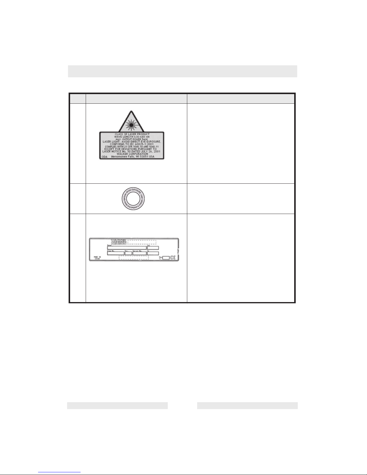
Ref. Label Meaning
A This instrument is a Class 3R laser,
manufactured to comply with the
international rules of safety IEC 60825-1,
2001. Although the power of the emission
of the beam is less than 5 mW in Class
3R, the following cautions are
recommended:
• Do not stare directly at the beam.
• Do not set up the laser at eye level.
B Avoid exposure. Laser radiation is
emitted from this aperture.
C A nameplate listing the model number,
item number, revision number, and serial
number is attached to each unit. Please
record the information found on this plate
so it will be available should the
nameplate become lost or damaged.
When ordering parts or requesting
service information, you will always be
asked to specify the model number, item
number, revision number, and serial
number of the unit.
Page 9

Operation VAL 300
wc_tx000802gb.fm EN-9
2. Operation
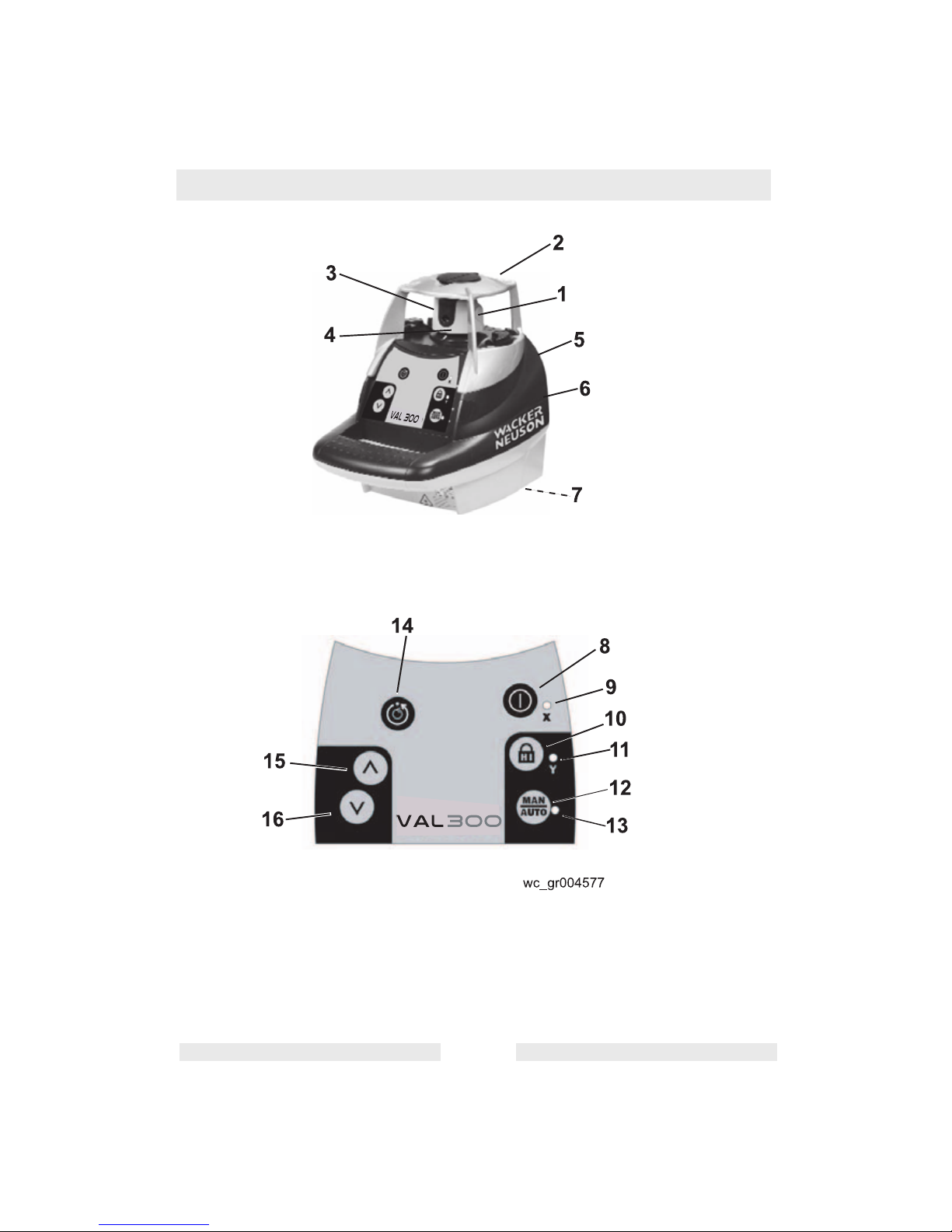
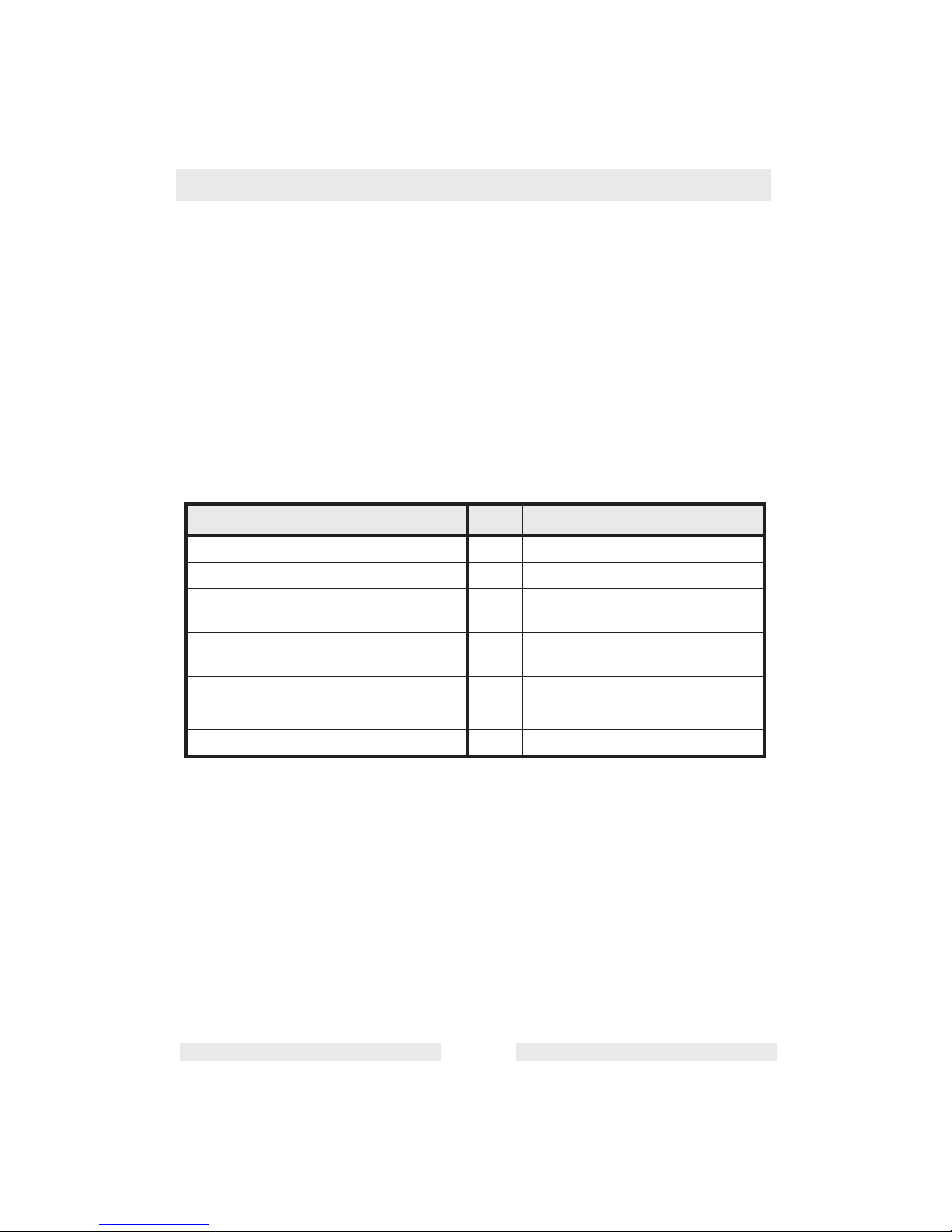
2.1 Set-up and Operation Locations
See Graphic: wc_gr004577
Italics correspond to indicators and keys used in calibration mode.
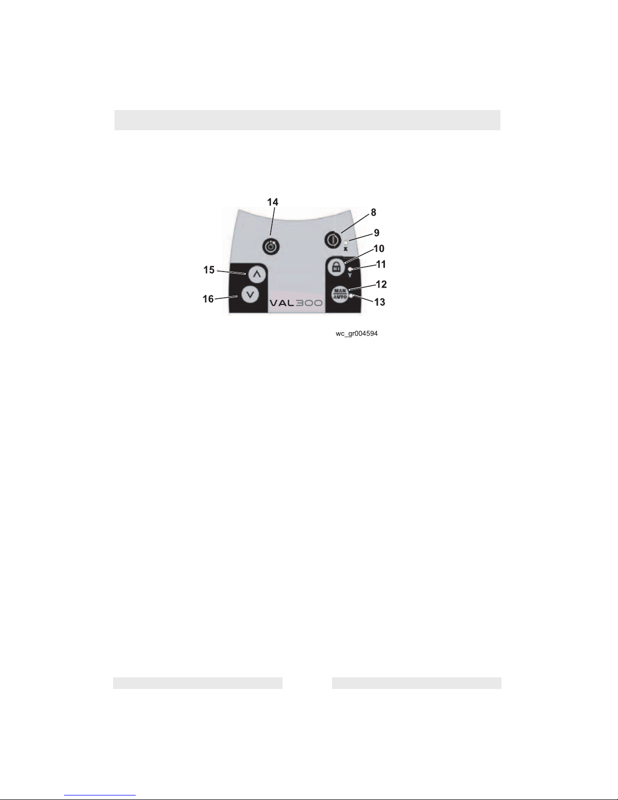
Ref. Description Ref. Description
1 Rotating head 9 Low battery indicator
X axis calibration LED
2 Aluminum head protection with
axes indications
10 H.I. (Height of Instrument)
Alert Function
Change calibration axis
3 Laser beam aperture 11 H.I. (Height of Instrument)
Alert Indicator
Y axis calibration LED
4 Index marks 12 Manual Function
Save calibration
5 Batteries 13 Manual mode indicator
6 Jack for battery charger 14 Rotation speed
7 5/8-11 tripod mount for horizontal
set-up
15 Set manual slope
Move calibration beam up
8 On / Off switch 16 Set manual slope
Move beam down
Page 10
VAL 300 Operation
wc_tx000802gb.fm EN-10
Page 11

Operation VAL 300
wc_tx000802gb.fm EN-11
2.2 Application
This Wacker Neuson laser transmitter is simple to use, yet it has
several advanced features:
• Automatic self-leveling in horizontal
• Visible laser beam
• Easy electronic calibration
• Match slope in X and Y axes
2.3 Calibration
It is important to check your laser for proper calibration. The laser is a precision instrument and it is important that you keep it calibrated and in proper
condition. The accuracy of your work is completely your responsibility and you
should check your instrument before beginning each job, and especially after
the instrument has taken a sharp jolt or been dropped, or when temperature
changes greater than 50 degrees F (28 degrees C) have occurred. See “Maintenance” for calibration procedures.
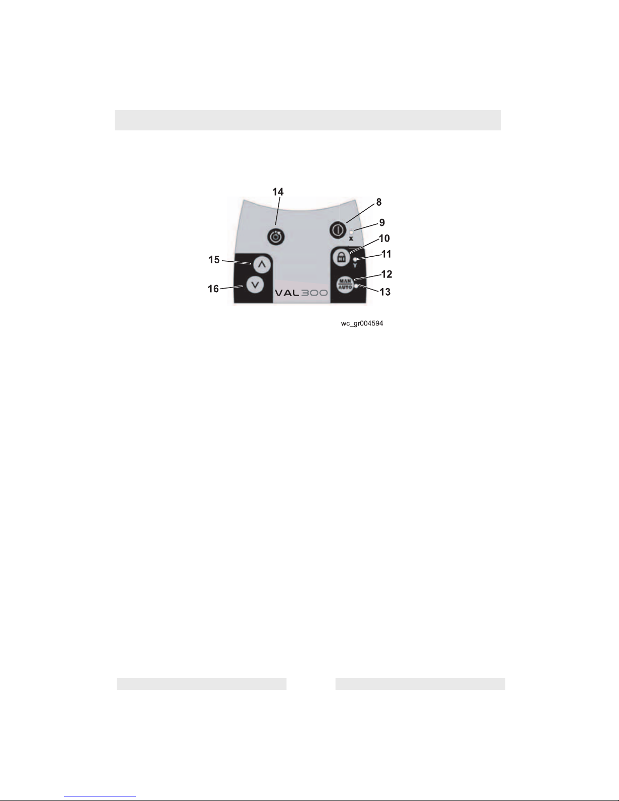
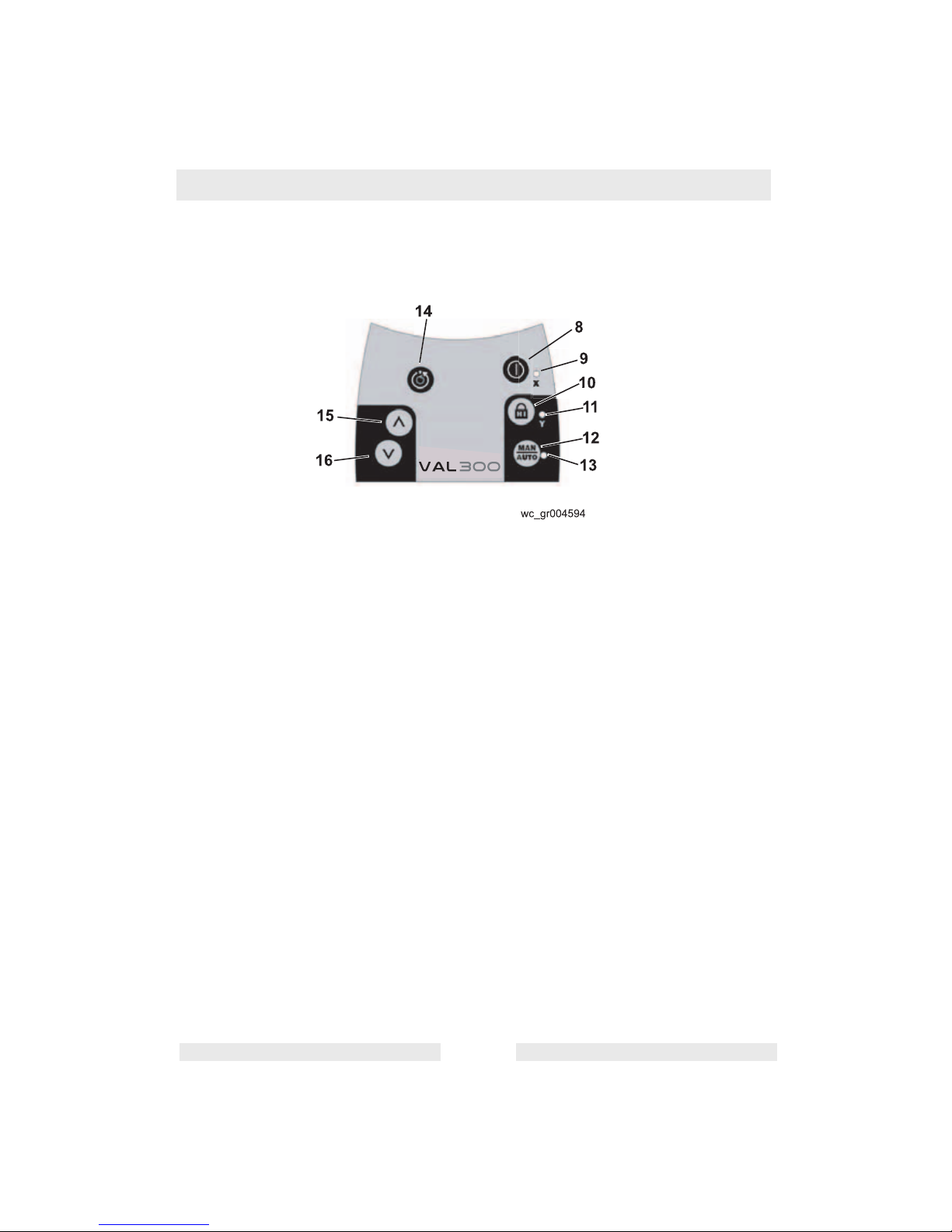
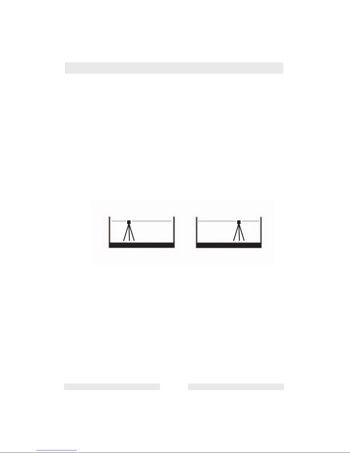
2.4 Horizontal Setup and Operation
See Graphic: wc_gr004594
2.4.1 The VAL 300 laser can be used directly on the ground or on a standard
5/8-11 tripod.
2.4.2 Press the ON/OFF switch (8) to turn the laser on. The laser will perform
a self-test when turned on. The beam will blink while the laser is selfleveling. After it has leveled, the head will start to rotate.
2.4.3 Select the H.I. (Height of Instrument) alert by pressing the H.I. Alert
Function key (10). The H.I. alert function will be active 30 seconds after
the VAL 300 has finished its self-leveling.
2.4.4 There are three rotation speeds: 0, 90 rpm and 600 rpm (the default
speed). To change to 90 rpm, press the rotation speed key (14). Press
the key again to stop the rotation.
2.4.5 To turn the laser off, press the ON/OFF switch.
Page 12
VAL 300 Operation
wc_tx000802gb.fm EN-12
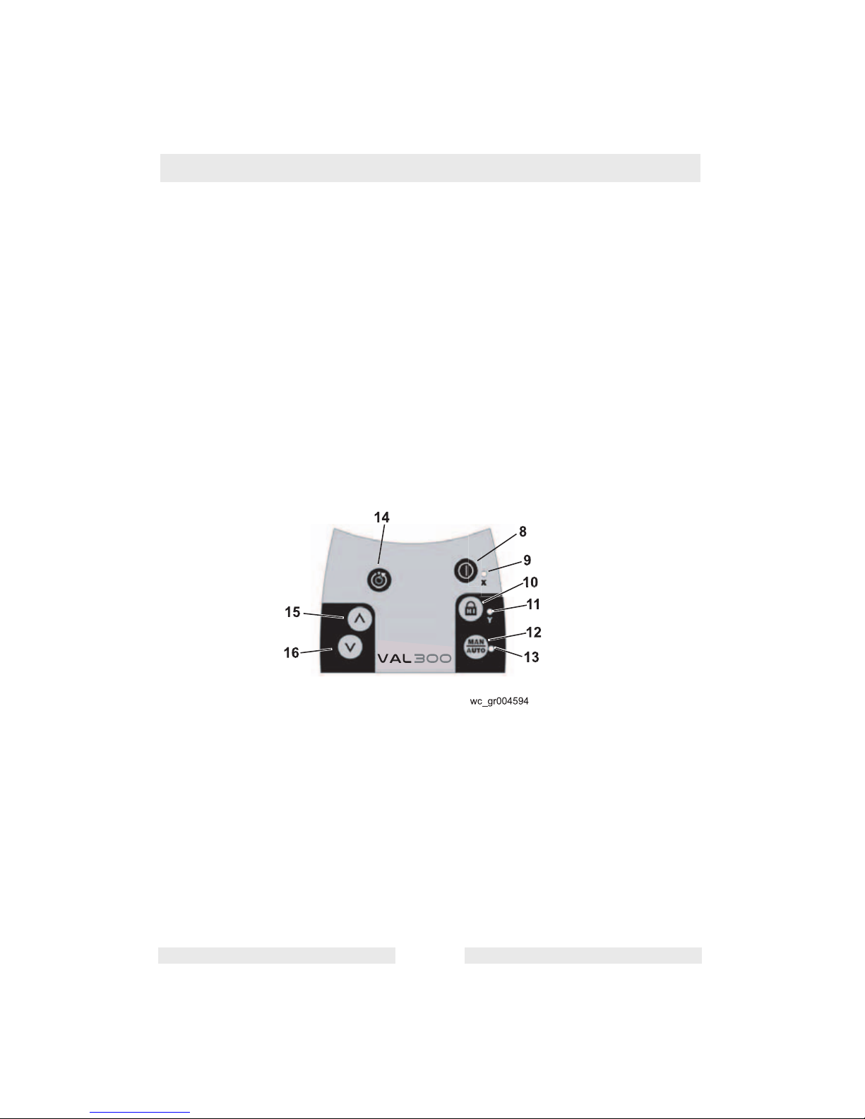
2.5 H.I. (Height of Instrument) Alert
See Graphic: wc_gr004594
2.5.1 The H.I. Alert feature stops the laser automatically and sounds an
alarm if the laser is disturbed, preventing inaccurate readings. It
functions only when selected.
2.5.2 To activate this safeguard feature, press the H.I. Alert Function key
(10) after turning the laser on. The H.I. Alert Indicator LED (11) will
blink rapidly while the laser is self-leveling.
2.5.3 About 30 seconds after the head starts to rotate, the LED will blink
slowly, indicating the H.I. Alert is activated.
2.5.4 If the laser is disturbed while in H.I. Alert mode, the head will stop
rotating, the beam will turn off, the LED indicator will stay on
continuously, and an alarm will sound for 30 seconds.
2.5.5 To reset the laser after an H.I. Alert, turn the laser off and turn it on
again. Check to see if the beam elevation has changed from its original
benchmark position.
2.5.6 The laser is no longer in H.I. Alert mode. Press the H.I. Alert Function
key to return to H.I. Alert.
2.5.7 While using the laser, check periodically to make sure that it has not
been moved and that your settings are still accurate.
Page 13

Operation VAL 300
wc_tx000802gb.fm EN-13
2.6 Rotation Speed
See Graphic: wc_gr004594
2.6.1 There are 3 rotation speeds: 0, 90 and 600 rpm (the default speed). To
change to 90 rpm, press the Rotation Speed key (14). Press again to
stop rotation.
2.6.2 The laser beam is more visible at the slower speed. It's also possible
to stop the rotation and use the beam as a point to view from a greater
distance.
Page 14

VAL 300 Operation
wc_tx000802gb.fm EN-14
2.7 Slope Match
See Graphic: wc_gr004594
2.7.1 The laser can be used to match manual slope on both X and Y axes.
Two modes are available:
• Complete manual mode: X and Y axis will be both manual
• Semi-automatic mode: X in automatic / Y in manual
Semi-automatic mode
2.7.1 Set the laser over a start point. Turn the laser so that Y on the top of
the head protection faces the direction of the slope (and Y' faces
away). Sight along the Y and Y' marks to roughly align the Y axis of the
laser to the second point.
2.7.2 After turning the laser on and allowing it to self-level, hold the Manual
Function (MAN) key (12) for a few seconds until the LED next to it (13)
is lit continually. The laser is now in manual mode in Y axis and
automatic self-leveling mode in X axis.
2.7.3 Press ^ (15) on the keypad to match a positive slope in Y and v (16) to
set a negative slope; the X axis will stay level.
2.7.4 Press twice on the MAN key to return to the automatic mode.
Manual Mode
2.7.1 Set the laser over a start point. Turn the laser so that X on the top of
the head protection faces the direction of the slope (and X' faces
away). Sight along the X and X' marks to roughly align the X axis of the
laser to the second point.
2.7.2 After turning the laser on and allowing it to self-level, press the MAN
key (12). The LED next to it (13) will blink, indicating you're in manual
mode and can match slope in the X axis. The head will start rotating.
2.7.3 Press ^ (15) on the keypad to match a positive slope in X and v (16) to
set a negative slope.
2.7.4 To switch to the Y axis, press the H.I. Alert Function key (12). Both
LEDs (11 and 13) will blink, indicating you’re in manual mode and can
match slope in the Y axis. Note: The Y axis grade will be at a 90 degree
angle from the X axis grade output.
2.7.5 Press ^ (15) on the keypad to match a positive slope in Y and v (16) to
set a negative slope.
2.7.6 Press the MAN key to return to automatic mode.
Note: In manual mode, the beam rotates even if the laser is not
leveled. The H.I. Alert function is not available when the unit is in
manual mode.
Page 15

Operation VAL 300
wc_tx000802gb.fm EN-15
2.8 Power
When battery power is low, the laser head will stop rotating and the low
battery LED next to the On/Off key will stay on.
Installing alkaline batteries
2.8.1 Use a coin or a screwdriver to remove the cover of the battery
compartment at the back of the laser.
2.8.2 Insert two alkaline batteries (D size or LR20), following the polarities
indicated at the bottom of the battery compartment. (The + contact is
rounded and raised). When replacing the batteries, change both at the
same time.
2.8.3 Replace the compartment and tighten with a coin or screwdriver.
Using rechargeable batteries
Charge the NiCd battery pack for 15 hours before first using the laser.
2.8.1 Insert the charger plug into the jack located at the back of the laser.
2.8.2 Plug the charger into an electrical outlet (110 volts or 230 volts).
2.8.3 Charge the battery for 15 hours.
Later recharges
The laser can be charged when working if electricity is available on the
jobsite. Simply plug in the charger and keep working. You can also
remove the battery, replace it with the alkaline battery pack and charge
the rechargeable batteries.
For optimum life of the battery, we recommend that you charge the
battery after it is fully discharged. To assure battery life, do not charge
over 20 hours.
Always store and charge the laser in a dry and covered place. The
battery and charger can be damaged if they become damp.
Page 16
VAL 300 Operation
wc_tx000802gb.fm EN-16
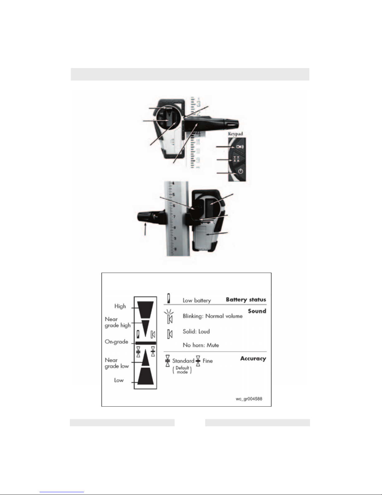
2.9 Laser Detector
Your laser transmitter is provided with a laser detector to be used with
a grade rod or handheld applications. Detectors are recommended
when it is difficult to see the laser beam, such as outdoors or in bright
light.
If you cannot pick up the beam with the detector, check how you are
lined up with the laser. One of the head protection supports on the
laser may be blocking the beam; move to the left or right to receive the
beam.
The head protection may be removed from the laser by pivoting the
two security locks. This will not affect the performance or the water or
dust resistance of the laser.
See graphic: wc_gr004586
Ref. Description Ref. Description
1 Level vial 8 ON / OFF
2 LCD screen (front) 9 Turn to attach clamp to detector
3 Detection window 10 Turn to tighten or remove clamp
from grade rod
4 Rod clamp 11 9V battery compartment
(Follow polarity indications inside)
5 On-grade alignment notch 12 Bubble vial to plumb rod
6 Choice of sound level 13 LCD screen (rear)
7 Choice of accuracy
Page 17
Operation VAL 300
wc_tx000802gb.fm EN-17
wc_gr004586
1
2
3
4
5
6
7
8
9
10
13
12
11
LCD Display
Page 18

VAL 300 Operation
wc_tx000802gb.fm EN-18
See graphic: wc_gr004586 and wc_gr004588
Using the detector:
2.9.1 Press the ON / OFF key (8) to turn on the detector.
2.9.2 Press the middle key (7) to select the accuracy (deadband).
2.9.3 Press the top key (6) to select the sound level.
2.9.4 Turn the detection window (3) towards the laser beam, and move the
detector up or down according to the information given on the LCD
screen (2). There are five channels of information, or grade indicators.
2.9.5 A down arrow indicates that you must move the detector down to reach
the laser reference; and up arrow indicates that you must move it up.
When a horizontal line appears on the display, the detector is at the
same level as the laser beam.
2.9.6 Press the ON / OFF key to turn the detector off. It will automatically
sound a warning beep and shut off after 10 minutes if not used.
2.9.7 Keep the detection window clean, using a soft cloth and glass cleaner.
2.10 Other Accessories
Contact your Wacker Neuson dealer for information about available
accessories.
Page 19

Maintenance VAL 300
wc_tx000805gb.fm EN-19
3. Maintenance
3.1 Checking and Adjusting
THIS SECTION IS VERY IMPORTANT: Here are a few simple
instructions to check your laser for calibration. The laser is a precision
instrument and it is important that you keep it calibrated and in proper
condition. The accuracy of your work is completely your responsibility
and you should check your instrument before beginning each job, and
especially after the instrument has taken a sharp jolt or been dropped,
or when temperature changes greater than 50 degrees F (28 degrees
C) have occurred.
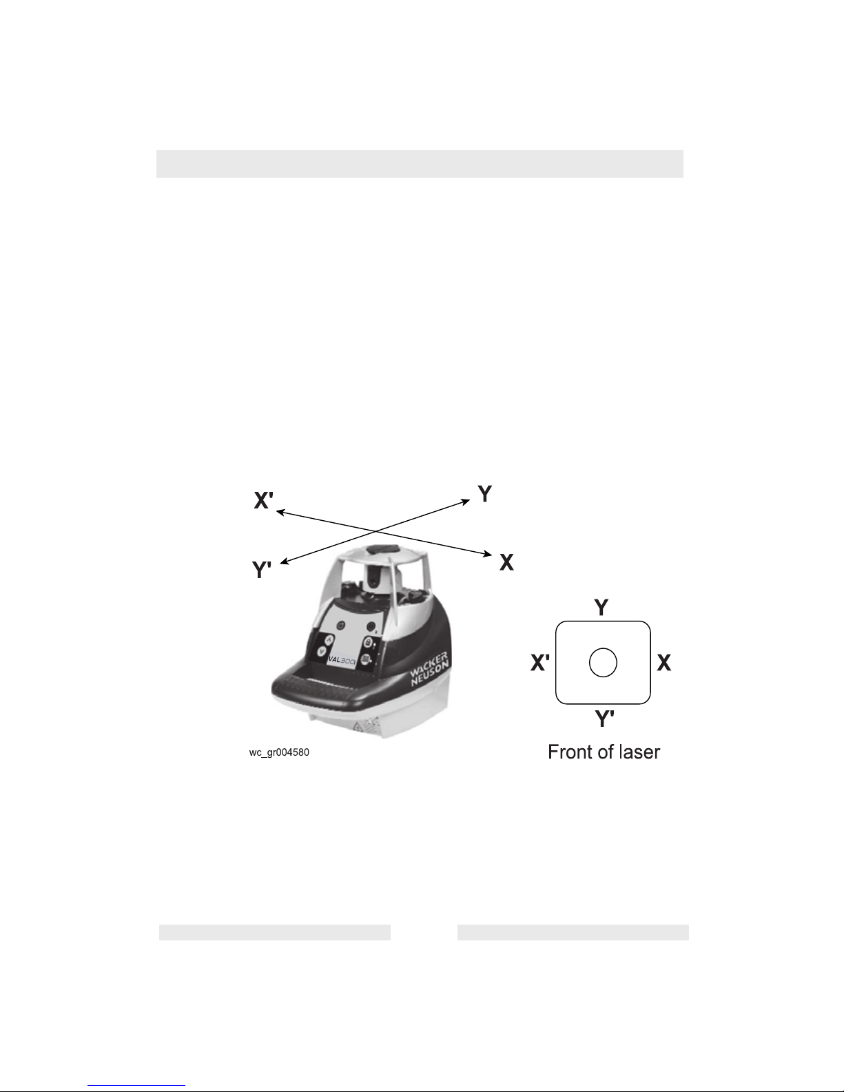
See graphic: wc_gr004580
The laser has two horizontal axes: X and Y, as indicated on the top of
the laser.
Each end of each axis must be checked for calibration. If needed, the
axis can be calibrated, carefully following the instructions. You can
also take the laser to a Wacker Neuson service center for calibration.
Page 20

VAL 300 Maintenance
wc_tx000805gb.fm EN-20
Check and calibrate in this order:
3.1.1 Check both sides of X axis.
• If X is within spec, proceed to check both sides of Y.
• If X needs calibration, calibrate X
3.1.2 Check both sides of Y axis.
• If Y is within spec, proceed to final X to Y check
• If Y needs calibration, calibrate Y; proceed to X to Y check
3.1.3 Final X to Y check: compare X, X', Y, Y'
3.2 Calibration Overview
3.2.1 Calibration is electronic, and is accomplished by using the laser
keypad. The optional detector/remote control or optional small remote
may also be used.
3.2.2 If the beam is visible, calibrate using the non-rotating point. If it is too
bright to see the beam, calibrate using the detector while the beam is
rotating. When you're in calibration mode, press the rotation key (7) on
the laser to rotate the beam.
3.2.3 The axis LED should blink slowly when in calibration mode. When the
laser is self-leveling or making an adjustment, the LED will blink
rapidly.
3.2.4 IMPORTANT: When pressing an arrow key to move the beam for
calibration, use short, rapid clicks. Do not hold the key down. One click
will move the beam a very small amount (1/32" at 150' or 1mm at
100m). After pressing the key, the LED will blink rapidly as the laser
reacts. Wait until the LED returns to a slow blink to proceed.
Page 21

Maintenance VAL 300
wc_tx000805gb.fm EN-21
3.3 Horizontal Checking and Calibration
3.3.1 Checking X axis
3.3.1.1 Place the laser on a flat surface or tripod 100 ft (30 m) away
from a wall. Position so that X' (noted on top of laser) is
facing the wall.
3.3.1.2 Turn on the laser.
3.3.1.3 Mark the location of the center of the beam. If it's too bright
to see the beam, use the detector.
3.3.1.4 Rotate the laser 180 degrees so that X faces the wall.
3.3.1.5 Mark the location of the center of the beam near the first
mark so that both marks are in line, one above the other.
3.3.1.6 At 100 ft., the marks should be no more than 3/16" apart. (At
30 m, no more than 5 mm apart.) This is within the stated
accuracy of ± 3/32" at 100 ft. (± 0.0075%).
3.3.1.7 If the marks are close enough, X axis is within calibration.
The second axis Y must then be checked (see later
section).
3.3.1.8 If the marks are not close enough, the X axis needs to be
calibrated.
Page 22
VAL 300 Maintenance
wc_tx000805gb.fm EN-22
3.3.2 Calibrating X axis
See graphic: wc_gr004594
The laser must be calibrated to bring the beam to the center of the two
X marks. Read "Calibration Overview" before proceeding.
3.3.2.1 Turn off the laser.
3.3.2.2 Hold the MAN key (12). While holding, momentarily press
the ON key (8).
3.3.2.3 After the LEDs blink in sequence, release the MAN key.
3.3.2.4 X LED will blink rapidly, indicating leveling. When the LED
blinks slowly, the laser is ready to calibrate.
3.3.2.5 If you have not moved the laser, use the X marks made in
previous steps of "Checking X axis".
3.3.2.6 Use the arrows on the keypad to move the beam up or
down to the halfway mark. If the X axis is toward the wall
with the marks, use the ^ key (15) to raise the beam, and
the v key (16) to lower the beam.
3.3.2.7 After completing the X calibration, press the H.I. Alert
Function key (10) to change the axis and to calibrate the Y
axis. (On the remote, press the double arrow key >>l)
3.3.2.8 If the Y axis doesn't have to be calibrated, press the MAN
key to save the calibration you've just made on the X axis.
(On the remote, use key with the small dot.)
If you are not sure of the calibration, don't save it and turn the laser off
using the ON / OFF key.
Page 23
Maintenance VAL 300
wc_tx000805gb.fm EN-23
3.3.3 Checking Y axis
3.3.3.1 Rotate the laser 90 degrees so that Y' is facing the wall.
3.3.3.2 Mark the location of the center of the beam.
3.3.3.3 Rotate the laser 180 degrees so that Y faces the wall.
3.3.3.4 Mark the location of the beam center near the first mark.
3.3.3.5 At 100 ft., the marks should be no more than 3/16" apart. (At
30 m, no more than 5 mm apart.) This is within the stated
accuracy of ± 3/32" at 100 ft. (± 0.0075%).
3.3.3.6 If the marks are close enough, Y axis is within calibration.
3.3.3.7 Proceed to "Final X to Y Check." If the marks are not close
enough, Y axis needs to be calibrated.
3.3.4 Calibrating Y axis
See graphic: wc_gr004594
The laser must be calibrated to bring the beam to the center of the two
Y marks.
If you are still in calibration mode from the X axis, turn Y towards the
wall and press the H.I. key to change to the Y axis. When the Y LED
blinks slowly, it's ready to be calibrated in Y axis.
If you're no longer in calibration mode:
3.3.4.1 Turn off the laser.
3.3.4.2 Hold the MAN key (12). While holding, momentarily press
the ON key (8).
3.3.4.3 After the LEDs blink in sequence, release the MAN key.
Page 24

VAL 300 Maintenance
wc_tx000805gb.fm EN-24
3.3.4.4 Select the Y axis by pressing the HI Alert Function key (10)
on the laser keypad (on the remote, press the double arrow
key >>l ).
3.3.4.5 Y LED will blink rapidly, indicating leveling. When the LED
blinks slowly, the laser is ready to calibrate.
3.3.4.6 If you have not moved the laser, use the Y marks made in
previous steps of "Checking Y axis".
3.3.4.7 Use arrows on the keypad to move the beam up or down to
the halfway mark. If the Y axis is toward the wall with the
marks, use the ^ key (15) to raise the beam, and the v key
(16) to lower the beam.
3.3.4.8 Press the MAN key to save the calibration you've just made
on the Y axis. (On remote, use key with the small dot).
If you are not sure of the calibration, don't save it and turn the laser off
using the On/Off key.
3.3.5 Final X to Y Check
As a final check, compare X and Y axes to be sure that your adjusted
calibration is within the specs of ± 3/32”. The marks for X, X', Y, and Y'
should be no more than 3/16" apart at 100 ft. (5 mm at 30 m).
Page 25
Maintenance VAL 300
wc_tx000805gb.fm EN-25
3.4 Cone Error Checking
3.4.1 Set up the laser 2 ft. (60 cm) from a wall (a) or a pole and 100 ft. (30
m) from another wall or pole (b).
3.4.2 Turn the laser on.
3.4.3 After the laser has self-leveled, stop the rotation and mark the location
of the beam (center of the beam) on the near wall (a), using the
detector if ambient conditions are too bright.
3.4.4 Rotate the laser 180° and mark the location of the center of the beam
on the far wall (b).
3.4.5 Now set up the laser 2 ft (60 cm) from the far wall. When the laser has
self-leveled, line up the beam on the previous mark (b).
3.4.6 Mark the location of the beam on the wall near the first mark (a).
3.4.7 Compare the two measurements. If the difference between aa'-bb' is
more than 3/16" or 5 mm, contact your local Wacker Neuson service
center.
wc_gr004596
a
b
Step 3 Step 4
a'
b'
Step 6 Step 5
Page 26

VAL 300 Maintenance
wc_tx000805gb.fm EN-26
3.5 Care and Handling
The use of controls or adjustments or performance of procedures other
than those specified herein may result in hazardous radiation
exposure.
3.5.1 The laser is a precision instrument which must be handled with care.
Avoid shock and vibrations. Always store and transport the laser and
its accessories in the carrying case.
3.5.2 Although the laser is weather resistant, make sure to clean and dry it
with a soft cloth after each use. This will increase the battery life.
3.5.3 Do not store your laser at temperatures below -4°F (-20°C) or above
176°F (80°C) because some electronic components could be
damaged.
3.5.4 To avoid water condensation inside the instrument, do not store it
inside the case if the instrument or the case is wet.
3.5.5 To maintain the laser’s precision, check and calibrate the beam
regularly.
3.5.6 Keep the aperture lens dry and clean. Use a soft cloth and glass
cleaner to clean it.
3.5.7 Charge the batteries regularly. However, charge them only when they
are nearly drained or completely out of power. Recharging batteries
that are still usable will shorten their capacity.
3.6 Troubleshooting
For laser repair, calibration, or warranty repair, please contact
EQUIPRO at 1-866-378-4776.
CAUTION
Page 27

Technical Data VAL 300
wc_td000244gb.fm EN-27
4. Technical Data
4.1 VAL 300 Laser Level
Part No.
VAL 300
0620406
0620475
Laser Level
Operating range
m (ft)
300 (1000)
diameter
Leveling range ± 5.7° (± 10%)
Slope match Up to 10% in X and Y axes (manual
mode); also X automatic and Y man-
ual (semi-automatic mode)
Accuracy ± 1/8-inch @ 100 feet
(± 10 mm / 100 m)
± 0.010%
Rotation speed
rpm
0–90–600
Beam type / output Class 3R, wavelength 635nm
Max. output power: 5mW
Power sources 2 D-size (LR20) alkaline batteries
or rechargeable batteries
Battery life
hours
Approximately 160 (alkaline)
40 (rechargeable NiCd)
Charging time
hours
15
Environmental Weatherproof, IP64
(rain and dust proof)
Dimensions and weight
cm (in)
kg (lbs.)
19.5 x 21 x 14 (7.75 x 8 x 5.5)
1.4 (3)
Page 28
VAL 300 Technical Data
wc_td000244gb.fm EN-28
4.2 Laser Detector
Part No.
Laser Detector
0147101
Laser Detector
Range
m (ft.)
150 (500)
Accuracy
mm (in.)
Fine: ± 1 (1/16)
Standard: ± 2.5 (1/8)
Grade indication LCD and audible tones
Battery life
hours
50
Power source 9V alkaline
Environmental Waterproof (IP 66+)
Dimensions and weight
cm (in.)
kg (lbs.)
15 x 8 x 3.5 (6 x 3.25 x 1.5)
0.2 (0.35)
Page 29

VAL 300 Tabla de materias
wc_bo0171955es_001TOC.fm ES-1
1. Prólogo ES-2
2. Información sobre la seguridad ES-3
2.1 Seguridad en la operación ............................................................. ES-4
2.2 Seguridad en el mantenimiento ...................................................... ES-4
2.3 Ubicación de las calcomanías ........................................................ ES-5
2.4 Calcomanías de seguridad y operación ......................................... ES-5
3. Operación ES-6
3.1 Configuración y ubicaciones de operación ..................................... ES-6
3.2 Aplicación ....................................................................................... ES-8
3.3 Calibración ..................................................................................... ES-8
3.4 Disposición horizontal y operación ................................................. ES-8
3.5 Alerta H.I. (altura del instrumento) ................................................. ES-9
3.6 Velocidad de giro .......................................................................... ES-10
3.7 Coincidencia de la pendiente ....................................................... ES-11
3.8 Alimentación ................................................................................. ES-12
3.9 Detector de láser .......................................................................... ES-13
3.10 Otros accesorios .......................................................................... ES-15
4. Mantenimiento ES-17
4.1 Revisión y ajuste .......................................................................... ES-17
4.2 Generalidades sobre la calibración .............................................. ES-18
4.3 Revisión y calibración horizontal .................................................. ES-19
4.4 Revisión de errores en el cono ..................................................... ES-23
4.5 Cuidado y manipulación ............................................................... ES-24
4.6 Localización de problemas ........................................................... ES-24
5. Datos técnicos ES-25
5.1 Nivel láser VAL 300 ...................................................................... ES-25
5.2 Detector de láser .......................................................................... ES-26
Page 30

wc_tx001231es.fm ES-2
Prefacio
El presente manual proporciona información y procedimientos para
operar y mantener en forma segura este modelo de Wacker Neuson.
Para su propia seguridad y protección contra lesiones, lea, comprenda
y acate cuidadosamente las instrucciones de seguridad descritas en
este manual.
Mantenga este manual o una copia con la máquina. Si extravía este
manual o necesita una copia adicional, comuníquese con Wacker
Neuson Corporation. Esta máquina está construida teniendo en mente
la seguridad del usuario; sin embargo, puede presentar riesgos si se
opera o se le da servicio incorrectamente. ¡Siga cuidadosamente las
instrucciones de operación! Si tiene consultas acerca de la operación
o servicio de este equipo, comuníquese con Wacker Neuson
Corporation.
La información contenida en este manual se basa en las máquinas
que están en producción al momento de la publicación. Wacker
Neuson Corporation se reserva el derecho de cambiar cualquier parte
de esta información sin previo aviso.
Se reservan todos los derechos, especialmente de copia y
distribución.
Copyright 2009 de Wacker Neuson Corporation.
Ninguna parte de esta publicación se puede reproducir en modo
alguno, ni por ningún medio, ya sea electrónico o mecánico,
incluyendo fotocopia, sin la autorización expresada por escrito de
Wacker Neuson Corporation.
Todo tipo de reproducción o distribución no autorizada por Wacker
Neuson Corporation infringe los derechos de autor válidos y será
penado por la ley. La empresa se reserva expresamente el derecho de
efectuar modificaciones técnicas (incluso sin previo aviso) con el
objeto de perfeccionar nuestras máquinas o sus normas de seguridad.
Page 31

VAL 300 Información sobre la seguridad
wc_si000241es.fm ES-3
1. Información sobre la seguridad
Este manual contiene notas de PELIGRO, ADVERTENCIA,
PRECAUCIÓN, AVISO y NOTA, las cuales precisan ser seguidas
para reducir la posibilidad de lesión corporal, daño a los equipos o
servicio incorrecto.
Este es el símbolo de alerta de seguridad. Se emplea para avisarle de
peligros potenciales de lesión corporal. Obedezca todos los mensajes
de seguridad a continuación de este símbolo para evitar posibles
daños corporales o la muerte.
PELIGRO indica una situación de riesgo que, si no se evita, causará
la muerte o lesión grave.
ADVERTENCIA indica una situación de riesgo que, si no se evita,
puede causar la muerte o lesión grave.
PRECAUCIÓN indica una situación de riesgo que, si no se evita,
puede causar lesión de grado menor o moderado.
AVISO: al usarse sin el símbolo de alerta de seguridad, AVISO indica
una situación de riesgo que, si no se evita, puede causar daños a
la propiedad.
Nota: Contiene información adicional importante para un procedimiento.
PELIGRO
ADVERTENCIA
PRECAUCIÓN
Page 32

Información sobre la seguridad VAL 300
wc_si000241es.fm ES-4
1.1 Seguridad en la operación
1.1.1 SIEMPRE lea, entienda y siga los procedimientos en el Manual de
operación, antes de intentar operar la máquina.
1.1.2 SIEMPRE almacene la máquina de manera adecuada cuando no la
utilice. La máquina deberá almacenarse en un lugar limpio y seco que
esté fuera del alcance de los niños.
1.1.3 SIEMPRE opere la máquina con todos los dispositivos de seguridad y
de protección colocados y en funcionamiento.
¡Posibles lesiones oculares! Cuando el láser no está girando, no mire
al haz de señalamiento.
1.2 Seguridad en el mantenimiento
¡Las máquinas con mantenimiento deficiente pueden presentar un
riesgo para la seguridad! A fin de que la máquina funcione en forma
segura y adecuada durante un largo período, es necesario realizar un
mantenimiento periódico y reparaciones ocasionales.
1.2.1 DEBEN realizarse todos los ajustes y las reparaciones antes de la
operación. ¡NUNCA opere la máquina a sabiendas de que hay un
problema o una deficiencia! Un técnico calificado deberá realizar todas
las reparaciones y los ajustes.
1.2.2 NO modifique la máquina sin la expresa aprobación por escrito del
fabricante.
1.2.3 SIEMPRE mantenga la máquina en condiciones de limpieza y las
calcomanías legibles. Vuelva a colocar todas las calcomanías
faltantes y cambie las que sean difíciles de leer. Las calcomanías
proporcionan instrucciones de operación importantes y advierten
sobre peligros y riesgos.
1.2.4 SIEMPRE realice el Mantenimiento periódico según las
recomendaciones en el Manual de operación.
PRECAUCIÓN
ADVERTENCIA
Page 33

VAL 300 Información sobre la seguridad
wc_si000241es.fm ES-5
1.3 Ubicación de las calcomanías
1.4 Calcomanías de seguridad y operación
Ref. Calcomanía Significado
A Este instrumento es un láser clase 3R,
fabricado según las reglas internacionales
de seguridad IEC 60825-1, 2001. Si bien la
potencia de la emisión del haz es inferior a
los 5 mW en Clase 3R, se recomienda
tomar las siguientes precauciones:
• No mire fijamente el haz.
• No instale el láser a la altura de la vista.
B Evite la exposición. La radiación del láser
se emite por esta abertura.
C Cada unidad posee una placa de
identificación con el número de modelo,
el número de referencia, el nivel de
revisión y el número de serie. Favor de
anotar los datos contenidos en la placa en
caso de que la placa de identificación se
dañe o pierda. En todos los pedidos para
repuestos o cuando se solicite información
de servicio, siempre se le pedirá que
especifique el número de modelo, el
número de referencia, el número de
revisión y el número de serie de la unidad.
Page 34

Operación VAL 300
wc_tx000802es.fm ES-6
2. Operación
2.1 Configuración y ubicaciones de operación
Ver gráfico: wc_gr004577
Las cursivas corresponden a los indicadores y teclas que se utilizan en el modo de calibración.
Ref. Descripción Ref. Descripción
1 Cabezal giratorio 9 Indicador de baja carga de pilas
LED de calibración del eje X
2 Protección de aluminio para el
cabezal con indicaciones de ejes
10 H.I. (altura del instrumento)
Función de alerta
Cambiar eje de calibración
3 Apertura del haz de láser 11 H.I. (altura del instrumento)
Indicador de alerta
LED de calibración del eje Y
4 Marcas de índice 12 Función Manual
Guardar calibración
5 Pilas 13 Indicador de modo manual
6 Toma para el cargador de pilas 14 Velocidad giratoria
7 Montura de trípode de 5/8-11
para disposición horizontal
15 Fijar pendiente manual
Subir haz de calibración
8 Interruptor On / Off
(Encendido / Apagado)
16 Fijar pendiente manual
Bajar haz
Page 35

VAL 300 Operación
wc_tx000802es.fm ES-7
Page 36

Operación VAL 300
wc_tx000802es.fm ES-8
2.2 Aplicación
Este transmisor láser Wacker es muy fácil de usar, aunque tiene
diversas funciones avanzadas:
• Nivelación automática en horizontal
• Haz láser visible
• Fácil calibración electrónica
• Concordancia de pendiente en ejes X e Y
2.3 Calibración
Es importante verificar la correcta calibración del láser. El láser es un
instrumento de precisión y es importante que se mantenga calibrado y en
condiciones óptimas. La precisión de su trabajo es una responsabilidad
completamente suya, por lo que debe revisar los instrumentos antes de
comenzar cada obra, y especialmente después de que el instrumento haya
sido sacudido bruscamente o se haya caído, o bien cuando se hayan
producido cambios de temperatura superiores a 50 grados F (28 grados C).
En la sección “Mantenimiento” encontrará los procedimientos de calibración.
2.4 Disposición horizontal y operación
Consulte el gráfico: wc_gr004594
2.4.1 El láser VAL 300 se puede usar directamente en el piso o bien en un
trípode estándar de 5/8-11.
2.4.2 Pulse el interruptor ON / OFF (ENCENDIDO / APAGADO) (8) para
encender el láser. El láser efectuará una autoprueba al encenderse. El
haz parpadeará cuando el láser se esté autonivelando. Una vez que
el láser se haya nivelado, el cabezal comenzará a girar.
2.4.3 Seleccione la alerta de H.I. (altura del instrumento) pulsando la tecla
de función H.I. (10). La función de alerta H.I. estará activa durante
30 segundos después de que el VAL 300 haya finalizado la
autonivelación.
2.4.4 Hay tres velocidades de rotación: 0, 90 RPM y 600 RPM, que es la
predeterminada. Para cambiar a 90 RPM, pulse la tecla de velocidad
de rotación (14). Pulse nuevamente dicha tecla para detener la
rotación.
2.4.5 Para apagar el láser, pulse el interruptor ON / OFF (ENCENDIDO /
APAGADO).
Page 37

VAL 300 Operación
wc_tx000802es.fm ES-9
2.5 Alerta H.I. (altura del instrumento)
Consulte el gráfico: wc_gr004594
2.5.1 La función de alerta H.I. detiene automáticamente el láser y emite una
alarma sonora si es que se ve alterado, evitando lecturas inexactas.
Funciona sólo cuando se selecciona.
2.5.2 Para activar esta función de seguridad, pulse la tecla de función H.I.
(10) después de encender el láser. El LED indicador de alerta de H.I.
(11) parpadeará rápidamente mientras el láser se está autonivelando.
2.5.3 Unos 30 segundos después de que el cabezal empiece a girar, el LED
parpadeará lentamente, indicando que la alerta de H.I. está activada.
2.5.4 Si el láser sufre alguna alteración mientras está en el modo de alerta
H.I., el cabezal dejará de girar, el haz se apagará, el indicador LED se
mantendrá encendido continuamente, y sonará una alarma durante
30 segundos.
2.5.5 Para restablecer el láser después de una alerta de H.I., apague el
láser y vuelva a encenderlo. Verifique si la elevación del haz ha
variado desde de su posición original.
2.5.6 El láser ya no está en el modo de alerta de H.I. Pulse la tecla de
función de alerta de H.I. para volver a dicho modo.
2.5.7 Al estar usando el láser, verifique periódicamente que no se haya
movido y que la configuración aún sea precisa.
Page 38

Operación VAL 300
wc_tx000802es.fm ES-10
2.6 Velocidad de giro
Consulte el gráfico: wc_gr004594
2.6.1 Hay tres velocidades de rotación: 0, 90 RPM y 600 RPM, que es la
predeterminada. Para cambiar a 90 RPM, pulse la tecla de velocidad
de rotación (14). Púlsela nuevamente para detener la rotación.
2.6.2 El haz de láser es más visible a la velocidad menor. También es
posible detener la rotación y usar el haz como punto de vista desde
una distancia mayor.
Page 39

VAL 300 Operación
wc_tx000802es.fm ES-11
2.7 Coincidencia de la pendiente
Consulte el gráfico: wc_gr004594
2.7.1 El láser se puede usar para hacer coincidir la pendiente manual en los
ejes X e Y. Hay dos modos disponibles:
• Modo manual completo: los ejes X e Y estarán en el modo manual
• Modo semiautomático: X en automático / Y en manual
Modo semiautomático
2.7.1 Fije el láser sobre un punto de partida. Gire el láser de modo que Y
encima de la protección del cabezal dé en dirección de la pendiente
(e Y’ dé hacia afuera). Observe las marcas Y e Y’ para alinear
someramente el eje Y del láser al segundo punto.
2.7.2 Tras encender el láser y dejar que se autonivele, mantenga pulsada la
tecla de función manual (MAN) (12) unos segundos hasta que el LED
situado junto a ella (13) quede encendido permanentemente. El láser
está en el modo manual en el eje Y y en el modo automático de
autonivelación en el eje X.
2.7.3 Pulse ^ (15) en el teclado para coincidir con una pendiente positiva en
Y y luego v (16) para fijar una pendiente negativa; el eje X se
mantendrá nivelado.
2.7.4 Pulse dos veces la tecla MAN para volver al modo automático.
Modo manual
2.7.1 Fije el láser sobre un punto de partida. Gire el láser de modo que X
encima de la protección del cabezal dé en dirección de la pendiente
(y X’ dé hacia afuera). Observe las marcas X y X’ para alinear
someramente el eje X del láser al segundo punto.
2.7.2 Tras encender el láser y dejar que se autonivele, pulse la tecla MAN
(12). El diodo LED (13) situado junto a ella parpadeará, indicando que
usted está en el modo manual y puede hacer coincidir la pendiente en
el eje X. El cabezal comenzará a girar.
2.7.3 Pulse ^ (15) en el teclado para coincidir con una pendiente positiva en
X y luego v (16) para fijar una pendiente negativa.
2.7.4 Para cambiar al eje Y, pulse la tecla H.I. (12) de función de alerta.
Ambos diodos LED (11 y 13) parpadearán, indicando que usted está
en el modo manual y puede hacer coincidir la pendiente en el eje Y.
Nota: La inclinación del eje Y estará en un ángulo de 90 grados desde
la salida de la inclinación del eje X.
2.7.5 Pulse ^ (15) en el teclado para coincidir con una pendiente positiva en
Y y luego v (16) para fijar una pendiente negativa.
2.7.6 Pulse la tecla MAN para volver al modo automático.
Nota: En el modo manual, el haz gira incluso si el láser no está
nivelado. La función de alerta de H.I. no está disponible cuando la
unidad está en el modo manual.
Page 40

Operación VAL 300
wc_tx000802es.fm ES-12
2.8 Alimentación
Cuando la carga de las pilas esté baja, el cabezal del láser dejará de
girar y se encenderá el LED indicador de carga baja situado junto a la
tecla On / Off (Encendido / Apagado).
Instalación de pilas alcalinas
2.8.1 Use una moneda o un destornillador para quitar la tapa del
compartimiento de las pilas en la parte trasera del láser.
2.8.2 Inserte dos pilas alcalinas (tamaño D o LR20), respetando la polaridad
indicada en la base del compartimiento. (El contacto + es redondeado
y está ligeramente levantado.) Cuando reemplace las pilas, reemplace
las dos a la vez.
2.8.3 Vuelva a poner la tapa del compartimiento y apriételo con una moneda
o destornillador.
Uso de pilas recargables
Cargue el paquete de pilas de NiCd durante 15 horas antes de usar el
láser por primera vez.
2.8.1 Inserte el enchufe del cargador en la toma situada en la parte trasera
del láser.
2.8.2 Enchufe el cargador en un tomacorriente eléctrico (110 ó 230 voltios).
2.8.3 Cargue la pila durante 15 horas.
Recargas posteriores
El láser se puede cargar durante su uso si se cuenta con electricidad
en el lugar de trabajo. Enchufe el cargador y siga trabajando. También
puede quitar la pila, reemplazarla por el paquete de pilas alcalinas y
cargar las pilas recargables.
Para lograr una óptima vida útil de las pilas, se recomienda que las
cargue después de que se hayan descargado por completo. Para
garantizar la vida útil de las pilas, no las cargue más de 20 horas.
Siempre almacene y cargue el láser en un lugar seco y protegido.
La pilas y el cargador se pueden dañar si es que se humedecen.
Page 41
VAL 300 Operación
wc_tx000802es.fm ES-13
2.9 Detector de láser
Su transmisor láser viene con un detector láser que se puede utilizar
con una varilla de rasante o en aplicaciones manuales. Se recomienda
usar detectores cuando sea difícil ver el haz del láser, como por
ejemplo, al aire libre o cuando haya una alta luminosidad.
Si no puede captar el haz con el detector, verifique cómo está alineado
usted respecto del láser. Uno de los soportes de la protección del láser
puede estar bloqueando el haz; muévalo a la izquierda o derecha para
recibir el haz.
La protección del cabezal se puede quitar del láser pivotando los dos
pestillos de seguridad. Esto no afectará el rendimiento ni la resistencia
del láser al agua y al polvo.
Consulte el gráfico: wc_gr004586
Ref. Descripción Ref. Descripción
1 Nivel de burbuja de aire 8 ON / OFF (ENCENDIDO / APAGADO)
2 Pantalla LCD (delantera) 9 Gire para fijar la presilla al detector
3 Ventana de detección 10 Gire para apretar o desprender la
presilla de la varilla de rasante
4 Presilla de la varilla 11 Compartimiento de pilas de 9V
(Acate la polaridad en su interior)
5 Muesca, alineación de graduación 12 Burbuja a varilla de plomada
6 Opción de nivel sonoro 13 Pantalla LCD (trasera)
7 Opción de precisión
Page 42

Operación VAL 300
wc_tx000802es.fm ES-14
wc_gr004586
1
2
3
4
5
6
7
8
9
10
13
12
11
LCD Display
Page 43

VAL 300 Operación
wc_tx000802es.fm ES-15
Consulte los gráficos: wc_gr004586 y wc_gr004588
Uso del detector:
2.9.1 Pulse la tecla ON / OFF (ENCENDIDO / APAGADO) (8) para
encender el detector.
2.9.2 Pulse la tecla intermedia (7) para seleccionar la precisión (banda
muerta).
2.9.3 Pulse la tecla superior (6) para seleccionar el nivel de sonido.
2.9.4 Gire la ventana de detección (3) hacia el haz de láser, y suba o baje el
detector según la información que aparezca en la pantalla LCD (2).
Hay cinco canales de información, o indicadores de inclinación.
2.9.5 Una flecha hacia abajo indica que debe bajar el detector hasta que
alcance la referencia del láser; y la flecha hacia arriba indica que debe
subirlo. Cuando aparezca una línea horizontal en la pantalla, el
detector está al mismo nivel que el haz del láser.
2.9.6 Pulse la tecla ON / OFF (ENCENDIDO / APAGADO) para apagar el
detector. Sonará automáticamente un tono de advertencia y se
apagará al cabo de 10 minutos si es que no se usa.
2.9.7 Mantenga la ventana de detección limpia, usando un paño
humedecido con líquido limpiavidrios.
2.10 Otros accesorios
Comuníquese con su distribuidor Wacker para obtener información
sobre los accesorios disponibles.
Page 44

Operación VAL 300
wc_tx000802es.fm ES-16
Notas
Page 45
VAL 300 Mantenimiento
wc_tx000805es.fm ES-17
3. Mantenimiento
3.1 Revisión y ajuste
ESTA SECCIÓN ES MUY IMPORTANTE: He aquí algunas sencillas
instrucciones para revisar la calibración del láser. El láser es un
instrumento de precisión y es importante que se mantenga calibrado
y en condiciones óptimas. La precisión de su trabajo es una
responsabilidad completamente suya, por lo que debe revisar los
instrumentos antes de comenzar cada obra, y especialmente después
de que el instrumento haya sido sacudido bruscamente o se haya
caído, o bien cuando se hayan producido cambios de temperatura
superiores a 50 grados F (28 grados C).
Consulte el gráfico: wc_gr004580
El láser tiene dos ejes horizontales: X e Y, tal como se indica en la
parte superior del láser.
Se debe revisar la calibración en cada uno de ellos. Si fuese
necesario, el eje se puede calibrar, siguiendo cuidadosamente las
instrucciones. También puede llevar el láser a un centro de servicio de
Wacker Neuson para que efectúen ahí la calibración.
Page 46

Mantenimiento VAL 300
wc_tx000805es.fm 18
Revise y realice la calibración en este orden:
3.1.1 Revise ambos lados del eje X.
• Si X está dentro de las especificaciones, proceda con la revisión
de ambos lados del eje Y.
• Calibre el eje X si fuese preciso.
3.1.2 Revise ambos lados del eje Y.
• Si Y está dentro de las especificaciones, proceda con la revisión
final de ambos ejes.
• Calibre el eje Y si fuese preciso y proceda con la revisión de
ambos ejes.
3.1.3 Revisión final de X a Y: compare X, X’, Y, Y’
3.2 Generalidades sobre la calibración
3.2.1 La calibración es electrónica, y se efectúa usando el teclado del láser.
También se puede usar el detector/control remoto opcional o control
remoto pequeño.
3.2.2 Si el haz es visible, lleve a cabo la calibración usando el punto no
giratorio. Si hay demasiada luz ambiental para verlo, haga la
calibración usando el detector mientras el haz está girando. Cuando
esté en el modo de calibración, pulse la tecla de rotación (7) en el láser
para girar el haz.
3.2.3 El LED del eje debe parpadear cuando la máquina esté en el modo de
calibración. Cuando el láser se esté autonivelando o realizando un
ajuste, el LED parpadeará rápidamente.
3.2.4 IMPORTANTE: Al presionar una tecla de flecha para mover el haz
cuando esté realizando la calibración, hágalo en forma breve y rápida.
No mantenga pulsada la tecla. Un clic moverá el haz una distancia
muy pequeña (1/32 pulg. a 150 pies ó 1 mm a 100 m). Tras pulsar la
tecla, el LED parpadeará rápidamente cuando reaccione el láser.
Espere hasta que el LED vuelva a parpadear lentamente para
continuar.
Page 47

VAL 300 Mantenimiento
wc_tx000805es.fm ES-19
3.3 Revisión y calibración horizontal
3.3.1 Revisión del eje X
3.3.1.1 Coloque el láser sobre una superficie plana o un trípode a
100 pies (30 m) de distancia de una pared. Colóquelo de
modo que X’ (marcada en la parte superior del láser) quede
hacia la pared.
3.3.1.2 Encienda el láser.
3.3.1.3 Marque la posición del centro del haz. Si hay demasiada
luminosidad para ver el haz, use el detector.
3.3.1.4 Gire el láser 180 grados de modo que X dé hacia la pared.
3.3.1.5 Marque la posición del centro del haz cerca de la primera
marca, de modo que ambas queden en línea, una sobre la
otra.
3.3.1.6 A 100 pies (30 m) las marcas no deben estar a una
distancia superior a 3/16 pulg. (5 mm) entre sí. Estos
valores están en los márgenes de precisión establecidos
de ± 3/32 pulg. a 100 pies (30 m) (± 0,0075%).
3.3.1.7 Si las marcas están lo suficientemente cerca entre sí, el eje
X está dentro de la calibración correcta. Luego se debe
revisar el segundo eje Y (consulte la sección que aparece
más adelante).
3.3.1.8 Si las marcas no están lo suficientemente cerca entre sí, es
preciso calibrar el eje X.
Page 48
Mantenimiento VAL 300
wc_tx000805es.fm 20
3.3.2 Calibración del eje X
Consulte el gráfico: wc_gr004594
El láser se debe calibrar para que el haz quede en el centro de las dos
marcas de X. Lea la sección “Generalidades sobre la calibración”
antes de continuar.
3.3.2.1 Apague el láser.
3.3.2.2 Mantenga pulsada la tecla MAN (12). Mientras lo hace,
pulse momentáneamente la tecla ON (8).
3.3.2.3 Después de que los LED parpadeen en secuencia, suelte
la tecla MAN.
3.3.2.4 El diodo LED de X parpadeará rápidamente, indicando la
nivelación. Cuando el LED parpadee lentamente, el láser
está listo para la calibración.
3.3.2.5 Si no movió el láser, use las marcas de X hechas en los
pasos anteriores de “Revisión del eje X”.
3.3.2.6 Use las flechas del teclado para subir o bajar el haz hasta
la marca de la mitad. Si el eje X está hacia la pared con las
marcas, use la tecla ^ (15) para elevar el haz, y la tecla
v (16) para bajarlo.
3.3.2.7 Tras completar la calibración de X, pulse la tecla de función
de alerta de H.I. (10) para cambiar de eje y calibrar el eje Y.
(En el control remoto, pulse la tecla de flecha doble >>l.)
3.3.2.8 Si no es necesario calibrar el eje Y, pulse la tecla MAN para
guardar la calibración que ha realizado recién en el eje X.
(En el control remoto, use la tecla con el punto pequeño).
Si no está seguro de la calibración, no la guarde y apague el láser con
la tecla ON / OFF (ENCENDIDO / APAGADO).
Page 49

VAL 300 Mantenimiento
wc_tx000805es.fm ES-21
3.3.3 Revisión del eje Y
3.3.3.1 Gire el láser 90 grados de modo que Y’ dé hacia la pared.
3.3.3.2 Marque la posición del centro del haz.
3.3.3.3 Gire el láser 180 grados de modo que Y dé hacia la pared.
3.3.3.4 Marque la posición del centro del haz cerca de la primera
marca.
3.3.3.5 A 100 pies (30 m), las marcas no deben quedar a una
distancia superior a 3/16 pulg. (5 mm) entre sí. Estos
valores están en los márgenes de precisión establecidos
de ± 3/32 pulg. a 100 pies (30 m) (± 0,0075%).
3.3.3.6 Si las marcas están lo suficientemente cerca entre sí, el eje
Y está dentro de la calibración correcta.
3.3.3.7 Proceda con la “Revisión final de los ejes X e Y”. Si las
marcas no están lo suficientemente cerca entre sí, es
preciso calibrar el eje Y.
3.3.4 Calibración del eje Y
Consulte el gráfico: wc_gr004594
El láser se debe calibrar para que el haz quede en el centro de las dos
marcas de Y.
Si aún está en el modo de calibración del eje X, gire Y hacia la pared
y pulse la tecla H.I. para cambiar al eje Y. Cuando el LED de Y
parpadee lentamente, está listo para calibrarse el eje Y.
Page 50

Mantenimiento VAL 300
wc_tx000805es.fm 22
Si ya no está en el modo de calibración:
3.3.4.1 Apague el láser.
3.3.4.2 Mantenga pulsada la tecla MAN (12). Mientras lo hace,
pulse momentáneamente la tecla ON (8).
3.3.4.3 Después de que los LED parpadeen en secuencia, suelte
la tecla MAN.
3.3.4.4 Seleccione el eje Y pulsando la tecla de función de alerta
de HI (10) en el teclado del láser (en el control remoto,
pulse la tecla de flecha doble >>l ).
3.3.4.5 El diodo de Y parpadeará rápidamente, indicando la
nivelación. Cuando el LED parpadee lentamente, el láser
está listo para la calibración.
3.3.4.6 Si no movió el láser, use las marcas Y hechas en los pasos
anteriores de “Revisión del eje Y”.
3.3.4.7 Use las flechas del teclado para subir o bajar el rayo hasta
la marca de la mitad. Si el eje Y está hacia la pared con las
marcas, use la tecla ^ (15) para elevar el haz, y la tecla v
(16) para bajarlo.
3.3.4.8 Pulse la tecla MAN para guardar la calibración que acaba
de realizar en el eje Y. (En el control remoto, use la llave
con el punto pequeño.)
Si no está seguro de la calibración, no la guarde y apague el láser
usando la tecla On / Off (Encendido / Apagado).
3.3.5 Revisión final de los ejes X e Y
Como revisión final, compare los ejes X e Y para cerciorarse de que la
calibración ajustada esté dentro de las especificaciones de
± 3/32 pulg. Las marcas para X, X’, Y e Y’ no deben ser superiores a
3/16 pulg. (5 mm) de separación a una distancia de 100 pies (30 m).
Page 51

VAL 300 Mantenimiento
wc_tx000805es.fm ES-23
3.4 Revisión de errores en el cono
3.4.1 Configure el láser a 2 pies (60 cm) de la pared (a) o un poste y
100 pies (30 m) de otra pared o poste (b).
3.4.2 Encienda el láser.
3.4.3 Después de haber autonivelado el láser, detenga la rotación y marque
la posición del haz (su centro) en la pared cercana (a), usando el
detector si las condiciones ambientales son muy brillantes.
3.4.4 Gire el láser 180° y marque la posición del centro del haz en la pared
lejana (b).
3.4.5 Ahora configure el láser a 2 pies (60 cm) de la pared lejana. Cuando
el láser se haya autonivelado, alinee el haz con la marca anterior (b).
3.4.6 Marque la posición del haz en la pared cercana a la primera marca (a).
3.4.7 Compare las dos mediciones. Si la diferencia entre aa'-bb' es superior
a 3/16 pulg. (5 mm), comuníquese con el centro de servicio local de
Wacker Neuson.
wc_gr004596
a
b
Step 3 Step 4
a'
b'
Step 6 Step 5
Page 52

Mantenimiento VAL 300
wc_tx000805es.fm 24
3.5 Cuidado y manipulación
El uso de controles, ajustes o procedimientos distintos a los
especificados en este documento pueden producir una exposición
peligrosa a la radiación.
3.5.1 El láser es un instrumento de precisión que se debe manipular con
cuidado. Evite descargas y vibraciones. Siempre almacene y traslade
el láser y sus accesorios en el maletín de transporte.
3.5.2 Si bien el láser es impermeable, cerciórese de limpiarlo y secarlo con
un paño suave después de cada uso. Esto aumentará la vida útil de la
pila.
3.5.3 No almacene el láser a temperaturas inferiores a los -4°F (-20°C) o
superiores a los 176°F (80°C) ya que algunos componentes
electrónicos se podrían dañar.
3.5.4 Para evitar la condensación del agua dentro del instrumento, no lo
almacene dentro de la caja si es que uno de los dos estuviera mojado.
3.5.5 Para mantener la precisión del láser, revise y calibre el haz
regularmente.
3.5.6 Mantenga el lente de apertura seco y limpio. Use un paño suave y un
líquido limpiavidrios para asearlo.
3.5.7 Cargue las pilas con frecuencia. Sin embargo, hágalo sólo cuando
estén casi o totalmente descargadas. Si recarga pilas que aún estén
utilizables disminuirá su capacidad.
3.6 Localización de problemas
Para la calibración o reparación del láser, o para una reparación por
garantía, comuníquese con su distribuidor o representante de Wacker
Neuson más cercano.
PRECAUCIÓN
Page 53

VAL 300 Datos técnicos
wc_td000244es.fm ES-25
4. Datos técnicos
4.1 Nivel láser VAL 300
Parte no.
VAL 300
0620406
0620475
Nivel a láser
Margen de operación
pies (m)
1000 (300)
diámetro
Margen de nivelación ± 5,7° (± 10%)
Coincidencia de pendiente Hasta 10% en los ejes X e Y (modo
manual); además en X automático e
Y manual (modo semiautomático)
Precisión ± 3/32 pulg. a 100 pies
(± 7.5 mm / 100 m)
± 0,0075%
Velocidad de rotación
RPM
0–90–600
Tipo / potencia de salida del haz Clase 3R, longitud de onda 635 nm
Máx. potencia de salida: 5 mW
Fuentes de alimentación 2 pilas alcalinas tamaño D (LR20)
o pilas recargables
Duración de las pilas
horas
Aproximadamente 160 (alcalinas)
40 (recargables de NiCd)
Tiempo de carga
horas
15
Ambientales Impermeable, IP64
(hidrófugo y hermético al polvo)
Dimensiones y peso
pulg. (cm)
lb. (kg)
7,75 x 8 x 5,5 (19,5 x 21 x 14)
3 (1,4)
Page 54

Datos técnicos VAL 300
wc_td000244es.fm ES-26
4.2 Detector de láser
Parte no.
Detector de láser
0147101
Detector de láser
Margen
pies (m)
500 (150)
Precisión
pulg. (mm)
Fina: ± 1 (1/16)
Estándar: ± 2,5 (1/8)
Indicación de inclinación LCD y tonos audibles
Duración de las pilas
horas
50
Fuente de energía Alcalina de 9V
Ambientales Impermeable (IP 66+)
Dimensiones y peso
pulg. (cm)
lb. (kg)
6 x 3,25 x 1,5 (15 x 8 x 3,5)
0,35 (0,2)
Page 55

Wacker VAL 300 Table des matières
wc_bo0171955fr_001TOC.fm FR-1
1. Préface FR-2
2. Information de sécurité FR-3
2.1 Mesures de sécurité liées au fonctionnement ................................ FR-4
2.2 Mesures de sécurité liées à l’entretien ........................................... FR-4
2.3 Emplacements des autocollants ..................................................... FR-5
2.4 Autocollants de sécurité et de fonctionnement ............................... FR-6
3. Fonctionnement FR-7
3.1 Emplacements de configuration et de fonctionnement .................. FR-7
3.2 Application ...................................................................................... FR-9
3.3 Calibrage ........................................................................................ FR-9
3.4 Configuration horizontale et utilisation ........................................... FR-9
3.5 Alerte H.I. (Hauteur de l’Instrument) ............................................. FR-10
3.6 Vitesse de rotation ........................................................................ FR-11
3.7 Réglage de la pente ..................................................................... FR-12
3.8 Alimentation .................................................................................. FR-13
3.9 Détecteur de laser ........................................................................ FR-14
3.10 Autres accessoires ....................................................................... FR-16
4. Maintenance FR-17
4.1 Vérification et ajustement ............................................................. FR-17
4.2 Survol du calibrage ....................................................................... FR-18
4.3 Vérification horizontale et calibrage ............................................. FR-19
4.4 Vérification de l’erreur conique ..................................................... FR-23
4.5 Entretien et manipulation .............................................................. FR-24
4.6 Dépannage ................................................................................... FR-24
5. Caractéristiques techniques FR-25
5.1 Niveau laser VAL 300 ................................................................... FR-25
5.2 Détecteur de laser ........................................................................ FR-26
Page 56

Préface
FR-2
1 Préface
Cette notice fournit de l’information et des procédures sur l’utilisation
sécuritaire et le maintien de ce modèle de Wacker Neuson. Pour votre
propre sécurité et protection contre les risques de blessure, veuillez
lire attentivement, bien assimiler et observer les consignes de sécurité
fournies dans cette notice.
Conserver cette notice ou un exemplaire avec la machine. Si cette
notice est perdue ou si l’on a besoin d’un autre exemplaire, contacter
la société Wacker Neuson Corporation. Cette machine a été conçue
avec comme objectif primordial la sécurité de l’utilisateur; toutefois,
elle peut présenter des dangers si elle n’est pas utilisée ou entretenue
correctement. Veuillez suivre attentivement les instructions
d’utilisation ! Pour toute question sur l’utilisation ou l’entretien de cet
équipement, contacter la société Wacker Neuson Corporation.
Les informations contenues dans cette notice portent sur des
machines en production au moment de la mise sous presse. La
société Wacker Neuson Corporation se réserve le droit de modifier
toute information sans préavis.
Tous les droits, en particulier les droits de copie et de distribution, sont
réservés.
Droit d’auteur 2009 par Wacker Neuson Corporation.
Il est interdit de reproduire tout ou une partie de cette publication, sous
quelque forme ou par quelque moyen que ce soit, électronique ou
mécanique, y compris par photocopie, sans l’autorisation écrite
préalable expresse de Wacker Neuson Corporation.
Tout type de reproduction ou de distribution non autorisé par Wacker
Neuson Corporation représente une violation des droits d’auteur en
vigueur et fera l’objet de poursuites. Nous nous réservons
expressément le droit d’apporter des modifications techniques, même
sans préavis, visant à améliorer nos machines ou leurs normes de
sécurité.
Page 57

VAL 300 Information de sécurité
wc_si000241fr.fm FR-3
2. Information de sécurité
Ce manuel contient des notations de DANGER, AVERTISSEMENT,
PRÉCAUTION, ATTENTION et REMARQUE à suivre pour réduire les
risques de blessures, de dommages à l’équipement ou d’un service
inadéquat.
Ce symbole signale une Alerte sécuritaire. Il est utilisé pour vous
avertir qu’il existe un risque potentiel de blessure corporelle.
Respecter toutes les consignes de sécurité qui suivent ce symbole
pour éviter une éventuelle blessure corporelle voire mortelle.
DANGER indique une situation dangereuse immédiate qui, si elle n’est
pas évitée, risque d’entraîner des blessures corporelles graves voire
mortelles.
AVERTISSEMENT indique une situation dangereuse qui, si elle n’est
pas évitée, risque d’entraîner des blessures corporelles graves voire
mortelles.
PRÉCAUTION indique une situation dangereuse qui, si elle n’est pas
évitée, risque d’entraîner des blessures corporelles mineures ou
modérées.
ATTENTION : utilisé sans le symbole de sécurité, ATTENTION
indique une situation dangereuse qui, si elle n’est pas évitée, risque
d’entraîner des dommages matériels.
Remarque : contient des informations complémentaires importantes
pour une procédure.
DANGER
AVERTISSEMENT
PRÉCAUTION
Page 58

Information de sécurité VAL 300
wc_si000241fr.fm FR-4
2.1 Mesures de sécurité liées au fonctionnement
2.1.1 TOUJOURS lire, comprendre et suivre les procédures dans la Notice
d’emploi avant de tenter d’utiliser l’appareil.
2.1.2 TOUJOURS ranger correctement l’équipement lorsqu’il n’est pas en
opération. L’équipement doit être rangé dans un endroit propre et sec,
hors de portée des enfants
2.1.3 TOUJOURS faire fonctionner l’appareil avec tous les dispositifs de
sécurité et les protections en place et en bon état.
Possibilité de dommage oculaire ! Lorsque le laser n’est pas en
rotation, ne pas regarder le faisceau pointé.
2.2 Mesures de sécurité liées à l’entretien
Une machine mal entretenue peut représenter un risque pour la
sécurité ! Pour que l’équipement fonctionne sans danger et
correctement pendant de longues périodes, il faut un entretien
périodique et des réparations occasionnelles.
2.2.1 Tous les réglages et toutes les réparations DOIVENT être complétés
avant l’opération. JAMAIS utiliser l’appareil sachant qu’un problème
ou une défectuosité existe ! Toutes les réparations et tous les réglages
devraient être effectués par un technicien qualifié.
2.2.2 NE PAS modifier l’appareil sans approbation écrite expresse du
fabricant.
2.2.3 TOUJOURS garder l’appareil propre et les autocollants lisibles.
Remplacer tous les autocollants manquants et difficiles à lire. Les
autocollants offrent des instructions importantes sur l’utilisation et
indiquent les dangers.
2.2.4 TOUJOURS effectuer la maintenance périodique tel que recommandé
dans le manuel de l’utilisateur.
PRÉCAUTION
AVERTISSEMENT
Page 59

VAL 300 Information de sécurité
wc_si000241fr.fm FR-5
2.3 Emplacements des autocollants
Page 60
Information de sécurité VAL 300
wc_si000241fr.fm FR-6
2.4 Autocollants de sécurité et de fonctionnement
Réf. Autocollant Signification
A Cet instrument est un laser de classe 3R,
fabriqué de façon à satisfaire aux normes
de sécurité internationales IEC 60825-1,
2001. Même si la puissance de l’émission
du faisceau est moins de 5 mW dans la
Classe 3R, les avertissements suivants
sont recommandés :
• Ne pas fixer votre regard directement
vers le faisceau.
• Ne pas installer le laser à la hauteur
des yeux.
B Éviter l’exposition. De la radiation laser
est émise par cette ouverture.
C Une plaque signalétique mentionnant le
numéro de modèle, le numéro de
référence, le niveau de révision et le
numéro de série de l’appareil se trouve sur
chaque unité. Veuillez inscrire l’information
qui se trouve sur la plaque signalétique
pour qu’elle soit disponible si la plaque est
perdue ou endommagée. En commandant
des pièces ou en demandant de
l’information de service, il faut toujours
mentionner le numéro de modèle, le
numéro de référence, le niveau de révision
et le numéro de série de l’unité.
Page 61

VAL 300 Fonctionnement
wc_tx000802fr.fm FR-7
3. Fonctionnement
3.1 Emplacements de configuration et de fonctionnement
Voir le graphique : wc_gr004577
Les italiques correspondent aux indicateurs et touches utilisés en mode calibrage.
Réf. Description Réf. Description
1 Tête rotative 9 Indicateur de batterie faible
DEL de calibrage de l’axe X
2 Protecteur de tête en aluminium
avec indications axiales
10 H.I. (Hauteur de l’Instrument)
Fonction Alerte
Changer l’axe de calibrage
3 Ouverture pour faisceau laser 11 H.I. (Hauteur de l’Instrument)
Indicateur Alerte
DEL de calibrage de l’axe Y
4 Indices de repérage 12 Fonction manuelle
Sauvegarder le calibrage
5 Batteries 13 Indicateur de mode manuel
6 Prise pour chargeur de batteries 14 Vitesse de rotation
7 Support de trépied 1,6 cm x 18 pour
configuration horizontale
15 Réglage manuel de la pente
Déplacer le faisceau de calibrage
vers le haut
8 Commutateur On / Off (Marche / Arrêt) 16 Réglage manuel de la pente
Déplacer le faisceau vers le bas
Page 62

Fonctionnement VAL 300
wc_tx000802fr.fm FR-8
Page 63

VAL 300 Fonctionnement
wc_tx000802fr.fm FR-9
3.2 Application
Ce transmetteur laser Wacker est simple à utiliser, mais il possède
plusieurs fonctions avancées :
• Autonivellement à l’horizontale
• Faisceau laser visible
• Calibrage électronique facile
• Règle la pente sur les axes X et Y
3.3 Calibrage
Il est important de vérifier le calibrage correct de votre laser. Le laser est un
instrument de précision et il est important de le maintenir calibré et en bonne
condition. La précision de votre travail relève entièrement de votre
responsabilité et vous devriez vérifier votre instrument avant de démarrer
chaque projet, surtout à la suite d’un impact important ou d’une chute de
l’instrument, ou lorsque la température subit des écarts de plus de 28 °C. Voir
« Maintenance » pour les procédures de calibrage.
3.4 Configuration horizontale et utilisation
Voir le graphique : wc_gr004594
3.4.1 Le laser VAL 300 peut être utilisé directement sur le sol ou sur un
trépied standard 5/8-11.
3.4.2 Appuyer sur le commutateur ON / OFF (MARCHE / ARRÊT) (8) pour
allumer le laser. Le laser effectuera son auto-diagnostique lorsqu’il
s’allumera. Le faisceau clignotera pendant que le laser effectue son
autonivellement. Après s’être mis au niveau, la tête se mettra à tourner.
3.4.3 Sélectionner Alerte H.I. (Hauteur d’Instrument) en appuyant sur la
touche Alerte H.I. (10). La fonction Alerte H.I. sera active pendant
30 secondes après que VAL 300 aura complété son autonivellement.
3.4.4 Il a trois vitesses de rotation : 0, 90 et 600 tr/min (la vitesse par défaut).
Pour la changer à 90 tr/min, appuyer sur la touche de vitesse de rotation
(14). Appuyer de nouveau sur la touche pour arrêter la rotation.
3.4.5 Pour éteindre le laser, appuyer sur le commutateur ON / OFF
(MARCHE / ARRÊT).
Page 64

Fonctionnement VAL 300
wc_tx000802fr.fm FR-10
3.5 Alerte H.I. (Hauteur de l’Instrument)
Voir le graphique : wc_gr004594
3.5.1 La fonction Alerte H.I. arrête le laser automatiquement et déclenche une
alarme si le laser est dérangé, ce qui empêcherait de faire des lectures
précises. Elle fonctionne seulement lorsqu’elle est sélectionnée.
3.5.2 Pour activer cette fonction sécuritaire, appuyer sur la touche de
fonction Alerte H.I. (10) après avoir allumé le laser. L’indicateur DEL
(11) Alerte H.I. clignotera rapidement pendant que le laser effectue
l’autonivellement.
3.5.3 Environ 30 secondes après le début de la rotation de la tête, la DEL
clignotera lentement, indiquant que l’Alerte H.I. est activée.
3.5.4 Si le laser est dérangé pendant qu’il est en mode Alerte H.I., la tête
cessera sa rotation, le faisceau s’éteindra, l’indicateur à DEL
s’allumera en continu et son alarme retentira pendant 30 secondes.
3.5.5 Pour réinitialiser le laser après une Alerte H.I., éteindre le laser et le
rallumer. Vérifier pour déterminer si l’élévation du faisceau a changé
de sa position repère originale.
3.5.6 Le laser n’est plus en mode Alerte H.I. Appuyer sur la touche de
fonction Alerte H.I. pour retourner au mode Alerte H.I.
3.5.7 Pendant l’utilisation du laser, le vérifier périodiquement pour vous
assurer qu’il n’a pas été déplacé et que vos réglages demeurent précis.
Page 65

VAL 300 Fonctionnement
wc_tx000802fr.fm FR-11
3.6 Vitesse de rotation
Voir le graphique : wc_gr004594
3.6.1 Il a trois vitesses de rotation : 0, 90 et 600 tr/min (la vitesse par défaut).
Pour la changer à 90 tr/min, appuyer sur la touche de vitesse de
rotation (14). Appuyer de nouveau pour arrêter la rotation.
3.6.2 Le faisceau laser est plus visible à la vitesse plus lente. Il est aussi
possible d’arrêter la rotation et d’utiliser le faisceau en tant que point
de mire à une plus grande distance.
Page 66

Fonctionnement VAL 300
wc_tx000802fr.fm FR-12
3.7 Réglage de la pente
Voir le graphique : wc_gr004594
3.7.1 Le laser peut servir à trouver la pente manuellement sur les axes X et
Y. Deux modes sont disponibles :
• Mode entièrement manuel : les axes X et Y seront tous deux
manuels.
• Mode semi-automatique : X en automatique / Y en manuel.
Mode semi-automatique
3.7.1 Régler le laser au-dessus d’un point de départ. Tourner le laser de
sorte que Y soit par-dessus la tête, avec les faces protectrices en
direction de la pente (et Y’ face à la direction opposée). Viser le long
des marques Y et Y’ pour finaliser l’alignement de l’axe Y du laser avec
le second point.
3.7.2 Après avoir allumé le laser et lui avoir permis de s’autoniveler, tenir la
touche de Fonction Manuelle (MAN) (12) pendant quelques secondes
jusqu’à ce que la DEL adjacente (13) demeure continuellement
allumée. Le laser est maintenant en mode manuel dans l’axe Y et en
mode d’autonivellement automatique dans l’axe X.
3.7.3 Appuyer ^ (15) sur le clavier pour régler une pente positive en Y et v
(16) pour régler une pente négative ; l’axe X demeurera à niveau.
3.7.4 Appuyer deux fois sur la touche MAN pour retourner au mode
automatique.
Mode manuel
3.7.1 Régler le laser au-dessus d’un point de départ. Tourner le laser de
sorte que X soit par-dessus la tête, avec les faces protectrices en
direction de la pente (et X’ face à la direction opposée). Viser le long
des marques X et X’ pour finaliser l’alignement de l’axe X du laser avec
le second point.
3.7.2 Après avoir allumé le laser et le laisser effectuer son autonivellement,
appuyer sur la touche MAN (12). La DEL adjacente (13) clignotera,
indiquant que vous êtes en mode manuel et pouvez régler la pente
dans l’axe X. La tête commencera sa rotation.
3.7.3 Appuyer ^ (15) sur le clavier pour régler une pente positive dans X et
v (16) pour régler une pente négative.
3.7.4 Pour changer à l’axe Y, appuyer la touche Alerte H.I. (12) Les deux
DELs (11 et 13) clignoteront, indiquant que vous êtes en mode manuel
et que vous pouvez régler la pente dans l’axe Y. Remarque : la pente
de l’axe Y sera à un angle de 90 degrés par rapport à la pente de la
sortie de l’axe X.
3.7.5 Appuyer ^ (15) sur le clavier pour régler une pente positive dans Y et
v (16) pour régler une pente négative.
Page 67

VAL 300 Fonctionnement
wc_tx000802fr.fm FR-13
3.7.6 Appuyer la touche MAN pour retourner au mode automatique.
Remarque : en mode manuel, le faisceau tourne même si le laser
n’est pas à niveau. La fonction Alerte H.I. n’est pas disponible pendant
que l’unité est en mode manuel.
3.8 Alimentation
Lorsque la charge des batteries est faible, la tête du laser cesse de
tourner and la DEL de batteries faibles à côté du commutateur On/Off
(Marche / Arrêt) restera allumée.
Installation de batteries alcalines
3.8.1 Utiliser une pièce de monnaie ou un tournevis pour retirer le couvercle
du compartiment à batteries derrière le laser.
3.8.2 Insérer deux batteries alcalines (grosseur D or LR20), en suivant les
indicateurs de polarité au fond du compartiment à batteries. (Le
contact + est arrondi et soulevé). Lors du remplacement de batteries,
remplacer les deux en même temps.
3.8.3 Replacer le compartiment et resserrer à l’aide de la pièce de monnaie
ou du tournevis.
Utilisation de batteries rechargeables
Charger le bloc-batterie NiCd pendant 15 heures avant la première
utilisation du laser.
3.8.1 Insérer le connecteur de charge dans la prise située à l’arrière du laser.
3.8.2 Brancher le chargeur dans une prise de secteur (110 volts ou 230 volts).
3.8.3 Charger la batterie pendant 15 heures.
Charges subséquentes
Le laser peut être chargé pendant qu’il est en opération si l’électricité
est disponible sur le chantier. Simplement brancher le chargeur et
continuer à travailler. Vous pouvez aussi retirer les batteries, les
remplacer par un bloc-batterie alcalines et charger les batteries
rechargeables.
Pour une durée de vie optimale des batteries, nous recommandons de
charger les batteries après qu’elles soient complètement déchargées.
Pour assurer la longévité des batteries, ne pas les charger pendant
plus de 20 heures.
Toujours ranger et charger le laser dans un endroit sec et couvert.
L’humidité peut endommager les batteries et le chargeur.
Page 68

Fonctionnement VAL 300
wc_tx000802fr.fm FR-14
3.9 Détecteur de laser
Votre transmetteur est équipé d’un détecteur de laser qui est utilisé sur
une perche de nivellement ou pour les applications à main. Les
détecteurs sont recommandés dans les situations où il est difficile de
voir le faisceau laser, telles qu’a l’extérieur ou lorsque la luminosité est
éblouissante.
Si vous ne pouvez pas capter le faisceau à l’aide du détecteur, vérifier
votre alignement avec le laser. Il se pourrait qu’un des supports de
protection sur le laser bloque le faisceau ; déplacez vous vers la
gauche ou la droite pour tenter de recevoir le faisceau.
La tête de protection peut s’enlever du laser en faisant pivoter les deux
verrous sécuritaires. Ceci n’affectera pas la performance ou la
résistance à l’eau et à la poussière du laser.
Voir le graphique : wc_gr004586
Réf. Description Réf. Description
1 Fiole de niveau 8 ON / OFF (MARCHE / ARRÊT)
2 Écran LCD (devant) 9 Tourner pour attacher la pince au
détecteur
3 Fenêtre de détection 10 Tourner pour resserrer or retirer la
pince de la perche de nivellement
4 Pince de perche 11 Compartiment de batteries 9V.
(Suivre les instructions sur la polarité
à l’intérieur)
5 Coche d’alignement sur-pente 12 Fiole en bulle pour vérifier l’aplomb de
la perche
6 Choix de niveau de son 13 Écran LCD (arrière)
7 Choix de précision
Page 69

VAL 300 Fonctionnement
wc_tx000802fr.fm FR-15
wc_gr004586
1
2
3
4
5
6
7
8
9
10
13
12
11
LCD Display
Page 70

Fonctionnement VAL 300
wc_tx000802fr.fm FR-16
Voir le graphique : wc_gr004586 et wc_gr004588
Utilisation du détecteur :
3.9.1 Appuyer sur la touche ON/OFF (MARCHE / ARRÊT) (8) pour allumer
le détecteur.
3.9.2 Appuyer sur la touche du milieu (7) pour sélectionner la précision
(zone morte).
3.9.3 Appuyer sur la touche supérieure (6) pour sélectionner le niveau de son.
3.9.4 Tourner la fenêtre de détection (3) dans la direction du faisceau laser,
puis déplacer le détecteur vers le haut ou le bas selon l’information
fournie sur l’écran LCD (2). Il y a cinq canaux d’information, ou
indicateurs de pente.
3.9.5 Une flèche vers le bas indique que vous devez déplacer le détecteur
vers le bas pour atteindre la référence du laser ; et la flèche vers le
haut indique que vous devez le déplacer vers le haut. Lorsqu’une ligne
horizontale apparaît sur l’écran, le détecteur est au même niveau que
le faisceau laser.
3.9.6 Appuyer sur la touche ON / OFF (MARCHE / ARRÊT) pour éteindre le
détecteur. Il émettra automatiquement un bip d’avertissement et
s’éteindra après 10 minutes d’inactivité.
3.9.7 Maintenez la propreté de la fenêtre de détection, utilisant un chiffon
doux et un nettoyeur pour vitres.
3.10 Autres accessoires
Contacter votre concessionnaire Wacker pour plus de renseignements
concernant les accessoires disponibles.
Page 71

VAL 300 Maintenance
wc_tx000805fr.fm FR-17
4. Maintenance
4.1 Vérification et ajustement
CETTE SECTION EST TRÈS IMPORTANTE : on y retrouve des
instructions simples pour vérifier le calibrage de votre laser. Le laser
est un instrument de précision et il est important de le maintenir calibré
et en bonne condition. La précision de votre travail relève entièrement
de votre responsabilité et vous devriez vérifier votre instrument avant
de démarrer chaque projet, surtout à la suite d’un impact important ou
d’une chute de l’instrument, ou lorsque la température subit des écarts
de plus de 28 °C.
Voir le graphique : wc_gr004580
Le laser a deux axes horizontaux : X et Y, tel qu’indiqué sur le dessus
du laser.
On doit vérifier le calibrage de chaque extrémité de chaque axe. Si
nécessaire, l’axe peut être calibré en suivant attentivement les
instructions. Vous pouvez aussi apporter votre laser dans un centre de
service Wacker Neuson pour être calibré.
Page 72

Maintenance VAL 300
wc_tx000805fr.fm FR-18
Vérifier et calibrer dans l’ordre suivant :
4.1.1 Vérifier les deux côtés de l’axe X.
• Si X est dans les normes, procéder à la vérification des deux
côtés de Y.
• Si X doit être calibré, calibrer X.
4.1.2 Vérifier les deux côtés de l’axe Y.
• Si Y est dans les normes, procéder à la vérification finale de X et Y.
• Si Y a besoin de calibrage, calibrer Y ; procéder à la vérification
de X et Y.
4.1.3 Vérification finale de X et Y : comparer X, X’, Y, Y’.
4.2 Survol du calibrage
4.2.1 Le calibrage est électronique, et s’accomplit en utilisant le clavier du
laser. On peut aussi utiliser le détecteur/commande à distance
optionnel ou la petite commande à distance.
4.2.2 Si le faisceau est visible, calibrer en utilisant le point non-tournant. S’il
les conditions sont trop éblouissantes pour voir le faisceau, calibrer à
l’aide du détecteur alors que le faisceau est en rotation. Lorsque vous
êtes en mode calibrage, appuyer sur la touche de rotation (7) sur le
laser pour faire tourner le faisceau.
4.2.3 La DEL de l’axe devrait clignoter lentement pendant le mode calibrage.
Lorsque le laser est en autonivellement ou effectue un ajustement, la
DEL clignotera rapidement.
4.2.4 IMPORTANT : en appuyant sur une touche en flèche pour déplacer le
faisceau pour le calibrage, effectuer des clics courts et rapides. Ne pas
tenir la touche enfoncée. Un clic fera avancer le faisceau par une très
petite distance, soit de 1 mm à 100 m. Après avoir appuyé sur la
touche, la DEL clignotera rapidement pendant que le laser réagit.
Attendre que la DEL reprenne le clignotement lent avant de continuer.
Page 73

VAL 300 Maintenance
wc_tx000805fr.fm FR-19
4.3 Vérification horizontale et calibrage
4.3.1 Vérification de l’axe X
4.3.1.1 Placer le laser sur une surface plane ou un trépied à 30 m
d’un mur. Le placer de façon à ce que X’ (indiqué sur le
dessus du laser) soit face au mur.
4.3.1.2 Allumer le laser.
4.3.1.3 Marquer l’emplacement du centre du faisceau. Si les
conditions sont trop éblouissantes pour voir le faisceau,
utiliser le détecteur.
4.3.1.4 Pivoter le laser par 180 degrés de façon à ce que X fasse
face au mur.
4.3.1.5 Marquer l’emplacement du centre du faisceau près de la
première marque de façon à ce que les deux marques
soient en ligne, une par-dessus l’autre.
4.3.1.6 À 30 m, les marques ne devraient pas être séparées par
plus de 5 mm. Ceci se trouve à l’intérieur de la précision
mentionnée de ± 2,5 mm à 100 m (± 0,0075%).
4.3.1.7 Si les marques sont suffisamment rapprochées, l’axe X est
dans les normes de calibrage. Le second axe Y doit être
vérifié (voir la section ci-dessous).
4.3.1.8 Si les marques ne sont pas suffisamment rapprochées,
l’axe X a besoin de calibrage.
Page 74

Maintenance VAL 300
wc_tx000805fr.fm FR-20
4.3.2 Calibrage de l’axe X
Voir le graphique : wc_gr004594
Le laser doit être calibré afin de porter le faisceau au centre des deux
marques X. Lire « Survol du calibrage » avant de continuer.
4.3.2.1 Éteindre le laser.
4.3.2.2 Tenir la touche MAN (12). En la tenant, appuyer
momentanément sur la touche ON (MARCHE) (8).
4.3.2.3 Lorsque la DEL clignote en séquence, relâcher la touche
MAN.
4.3.2.4 La DEL X clignotera rapidement, indiquant le nivellement.
Lorsque la DEL clignote lentement, le laser est prêt à être
calibré.
4.3.2.5 Si vous n’avez pas déplacé le laser, utiliser les marques de
X faites dans les étapes précédentes pour la « Vérification
de l’axe X ».
4.3.2.6 Utiliser les flèches sur le clavier pour déplacer le faisceau
vers le haut ou le bas jusqu’à la marque mitoyenne. Si l’axe
X pointe vers le mur qui a les marques, utiliser ^ (15) pour
soulever le faisceau, et la touche v (16) pour abaisser le
faisceau.
4.3.2.7 Après avoir complété le calibrage de X, appuyer sur la
touche de fonction Alerte H.I. (10) pour changer d’axe et
calibrer l’axe Y. (Sur la commande à distance, appuyer sur
la touche double flèche >>| )
4.3.2.8 Si l’axe Y n’a pas besoin d’être calibré, appuyer la touche
MAN afin de sauvegarder le calibrage que vous venez
d’effectuer sur l’axe X. (Sur la commande à distance,
utiliser la touche avec le petit point.)
Si vous n’êtes pas sûr du calibrage et ne voulez pas le sauvegarder,
éteindre le laser à l’aide de la touche ON / OFF (MARCHE / ARRÊT).
Page 75

VAL 300 Maintenance
wc_tx000805fr.fm FR-21
4.3.3 Vérification de l’axe Y
4.3.3.1 Tourner le laser par 90 degrés de façon à ce que l’axe Y’
fasse face au mur.
4.3.3.2 Marquer l’emplacement du centre du faisceau.
4.3.3.3 Pivoter le laser par 180 degrés de façon à ce que Y fasse
face au mur.
4.3.3.4 Marquer l’emplacement du centre du faisceau près de la
première marque.
4.3.3.5 À 30 m, les marques ne devraient pas être à plus de 5 mm
de séparation. Ceci se trouve à l’intérieur de la précision
mentionnée de ± 2,5 mm à 100 m (± 0,0075%).
4.3.3.6 Si les marques sont suffisamment rapprochées, l’axe Y est
dans les normes de calibrage.
4.3.3.7 Procéder à la « Vérification finale de X et Y ». Si les
marques ne sont pas suffisamment rapprochées, l’axe Y
doit être calibré.
4.3.4 Calibrage de l’axe Y
Voir le graphique : wc_gr004594
Le laser doit être calibré afin de porter le faisceau au centre des deux
marques de l’axe Y.
Si vous êtes encore en mode calibrage de l’axe X, tourner l’axe Y vers
le mur et appuyer sur la touche H.I. afin de changer à l’axe Y. Lorsque
la DEL Y clignote lentement, il est prêt pour le calibrage de l’axe Y.
Page 76

Maintenance VAL 300
wc_tx000805fr.fm FR-22
Si vous n’êtes plus en mode calibrage :
4.3.4.1 Éteindre le laser.
4.3.4.2 Tenir la touche MAN (12). En la tenant, appuyer
momentanément sur la touche ON (MARCHE) (8).
4.3.4.3 Lorsque la DEL clignote en séquence, relâcher la touche
MAN.
4.3.4.4 Sélectionner l’axe Y en appuyant sur la touche de fonction
Alerte H.I. (10) sur le clavier du laser (sur la commande à
distance, appuyer sur la flèche double >>| ).
4.3.4.5 La DEL Y clignotera rapidement, indiquant
l’autonivellement. Lorsque la DEL clignote lentement, le
laser est prêt à être calibré.
4.3.4.6 Si vous n’avez pas déplacé le laser, utiliser les marques de
Y faites dans les étapes précédentes pour la « Vérification
de l’axe Y ».
4.3.4.7 Utiliser les flèches sur le clavier pour déplacer le faisceau
vers le haut ou le bas jusqu’à la marque mitoyenne. Si l’axe
Y pointe vers le mur qui a les marques, utiliser ^ (15) pour
soulever le faisceau, et la touche v (16) pour abaisser le
faisceau.
4.3.4.8 Appuyer sur la touche MAN pour sauvegarder le calibrage
qui vient d’être effectué sur l’axe Y. (Sur la commande à
distance, utiliser la touche avec le petit point).
Si vous n’êtes pas sûr du calibrage et ne voulez pas le sauvegarder,
éteindre le laser à l’aide de la touche On / Off (Marche / Arrêt).
4.3.5 Vérification finale de X et Y
En vérification finale, comparer les axes X et Y pour vous assurer que
votre calibrage ajusté est dans les normes. Les marques pour X, X’, Y
et Y’ ne devraient pas être séparées par plus de 5 mm à 30 m.
Page 77

VAL 300 Maintenance
wc_tx000805fr.fm FR-23
4.4 Vérification de l’erreur conique
4.4.1 Configurer le laser à 60 cm d’un mur (a) ou d’une perche à 30 m d’un
autre mur ou perche (b).
4.4.2 Allumer le laser.
4.4.3 Après l’autonivellement du laser, arrêter la rotation et marquer
l’emplacement du faisceau (centre du faisceau) sur le mur rapproché
(a), à l’aide d’un détecteur si les conditions ambiantes sont trop
éblouissantes.
4.4.4 Tourner le laser par 180° et marquer l’emplacement du centre du
faisceau sur le mur éloigné (b).
4.4.5 Maintenant, configurer le laser à 60 cm du mur éloigné. Lorsque le laser
se sera autonivelé, aligner le faisceau sur la marque précédente (b).
4.4.6 Marquer l’emplacement du faisceau sur le mur près de la première
marque (a).
4.4.7 Comparer les deux mesures. Si la différence entre aa’-bb’ est plus
grande que 5 mm, contacter le centre de service local de Wacker
Neuson.
wc_gr004596
a
b
Step 3 Step 4
a'
b'
Step 6 Step 5
Page 78

Maintenance VAL 300
wc_tx000805fr.fm FR-24
4.5 Entretien et manipulation
L’utilisation de commandes ou des ajustements ou encore l’exécution
de procédures autres que celles spécifiées dans ce document pourrait
résulter en une exposition dangereuse à de la radiation.
4.5.1 Le laser est un instrument de précision qui doit être manipulé avec
soin. Éviter les chocs et les vibrations. Toujours ranger et transporter
le laser et ses accessoires dans son étui de transport.
4.5.2 Même si le laser est résistant à l’eau, assurez-vous de le nettoyer et
de le sécher avec un chiffon doux après chaque usage. Ceci
augmentera aussi la vie utile de la batterie.
4.5.3 Ne pas ranger votre laser à des températures sous -20 °C ou audessus de 80 °C parce que certains composants électroniques
pourraient être endommagés.
4.5.4 Pour éviter la condensation d’eau à l’intérieur, ne pas ranger celui-ci
dans son étui si l’instrument ou l’étui sont mouillés.
4.5.5 Afin de maintenir la précision du laser, vérifier et calibrer le faisceau
régulièrement.
4.5.6 Maintenir la lentille d’ouverture sèche et propre. Utiliser un chiffon
doux et un nettoyeur de verre pour le nettoyer.
4.5.7 Charger les batteries régulièrement. Par contre, les charger
uniquement lorsqu’elles sont presque ou complètement déchargées.
Recharger les batteries qui sont encore utilisables raccourcira leur
vie utile.
4.6 Dépannage
Pour réparer un laser, le calibrer, ou effectuer des réparations sous
garantie, veuillez contacter ÉQUIPRO à 1-866-378-4776.
PRÉCAUTION
Page 79

VAL 300 Caractéristiques techniques
wc_td000244fr.fm FR-25
5. Caractéristiques techniques
5.1 Niveau laser VAL 300
Article
VAL 300
0620406
0620475
Niveau laser
Plage opérationnelle
m
300
diamètre
Plage d’autonivellement ± 5,7° (± 10 %)
Réglage de la pente Jusqu’à 10 % pour les axes X et Y
(mode manuel); aussi X automatique
et Y manuel (mode semi-
automatique)
Précision ± 7,5 mm / 100 m
± 0,0075%
Vitesse de rotation
tr/min
0–90–600
Type de faisceau / sortie Classe 3R, longueur d’onde 635 nm
Puissance de sortie maxi : 5 mW
Sources d’alimentation 2 batteries alcalines grosseur D
(LR20) ou batteries rechargeables
Vie utile des batteries
heures
Environ 160 (alcaline)
40 (rechargeable NiCd)
Temps de charge
heures
15
Écologique Étanchéité, IP64
(à l’épreuve de la pluie et de
la poussière)
Dimension et poids
cm
kg
19,5 x 21 x 14
1,4
Page 80

Caractéristiques techniques VAL 300
wc_td000244fr.fm FR-26
5.2 Détecteur de laser
Article
Détecteur de laser
0147101
Détecteur de laser
Distance
m
150
Précision
mm
Fine : ± 1
Standard : ± 2,5
Indication de pente LCD et tons audibles
Vie utile des batteries
heures
50
Source d’alimentation 9V alcaline
Écologique Étanchéité (IP 66+)
Dimension et poids
cm
kg
15 x 8 x 3,5
0,2
Page 81

Page 82

Wacker Neuson SE · Preußenstraße 41 · D-80809 München · Tel.: +49-(0)89-3 54 02-0 · Fax: +49 - (0)89-3 54 02-390
Wacker Neuson Corporation · P.O. Box 9007 · Menomonee Falls, WI 53052-9007 · Tel. : (262) 255-0500 · Fax: (262) 255-0550 · Tel. : (800) 770-0957
Wacker Neuson Limited - Room 1701…03 & 1717…20, 17/F. Tower 1, Grand Century Place, 193 Prince Edward Road West, Mongkok, Kowloon, Hongkong.
Tel: (852) 3605 5360, Fax: (852) 2758 0032
AM 1041–05/09
 Loading...