

Page 1
Operator’s Manual
Trowel
CT 24-4A
0171799en 005 1010
0171799EN
Page 2

Copyright
notice
© Copyright 2010 by Wacker Neuson Corporation.
All rights, including copying and distribution rights, are reserved.
This publication may be photocopied by the original purchaser of the machine. Any
other type of reproduction is prohibited without express written permission from
Wacker Neuson Corporation.
Any type of reproduction or distribution not authorized by W acker Neuson Corp oration
represents an infringement of valid copyrights. Violators will be prosecuted.
T ra d emarks
Manufacturer
All trademarks referenced in this manual are the property of their respective owners.
Wacker Neuson Corporation
N92W15000 Anthony Avenue
Menomonee Falls, WI 53051 U.S.A.
Tel: (262) 255-0500 · Fax: (262) 255-0550 · Tel: (800) 770-0957
www.wackerneuson.com
Tra n slated
instructions
This Operator’s Manual presents the original instructions. The original language of this
Operator’s Manual is American English.
Page 3

CT 24-4A Foreword
Foreword
Machines
covered in
this manual
Machine Item Number
CT 24-24A 0620105, 0620849
Machine
documentation
Expectations
for
information in
this manual
Manufacturer’s
approval
Keep a copy of the Operator’s Manual with the machine at all times.
Use the separate Parts Book supplied with the machine to order replacement
parts.
If you are missing either of these documents, please contact Wacker Neuson
Corporation to order a replacement or visit www.wackerneuson.com.
When ordering parts or requesting service information, be prepared to provide
the machine model number, item number, revision number, and serial number.
This manual provides information and procedures to safely operate and
maintain the above Wacker Neuson model(s). For your own safety and to
reduce the risk of injury , carefully rea d, understand, and obse rve all instructions
described in this manual.
Wacker Neuson Corporation expressly reserves the right to make technical
modifications, even without notice, which improve the performance or safety
standards of its machines.
The information contained in this manual is based on machines manufactured
up until the time of publication. Wacker Neuson Corporation reserves the right
to change any portion of this information without notice.
This manual contains references to approved parts, attachments, and modifications. The following definitions apply:
Approved parts or attachments are those either manufactured or provided by
Wacker Neuson.
Approved modifications are those performed by an authorized Wacker
Neuson service center according to written instructions published by Wacker
Neuson.
Unapproved parts, attachments, and modifications are those that do not
meet the approved criteria.
Unapproved parts, attachments, or modifications may have the following consequences:
Serious injury hazards to the operator and persons in the work area
Permanent damage to the machine which will not be covered under warranty
Contact your Wacker Neuson dealer immediately if you have questions about
approved or unapproved parts, attachments, or modifications.
CALIFORNIA
Proposition
65 Warning
wc_tx001519gb.fm 3
Engine exhaust, some of its constituents, and certain vehicle components, contain
or emit chemicals known to the State of California to cause cancer and birth
defects or other reproductive harm.
Page 4

Foreword CT 24-4A
Laws
pertaining to
spark
arresters
NOTICE: State Health Safety Codes and Public Resources Codes specify that in
certain locations spark arresters be used on internal combustion engines that use
hydrocarbon fuels. A spark arrester is a device designed to prevent accidental discharge of sparks or flames from the engine exhaust. Spark arresters are qualified
and rated by the United States Forest Service for this purpose. In order to comply
with local laws regarding spark arresters, consult the engine distributor or the local
Health and Safety Administrator.
4 wc_tx001519gb.fm
Page 5

CT 24-4A Table of Contents
Foreword 3
1 Safety Information 7
1.1 Signal Words found in this Manual ....................................................... 7
1.2 Machine Description and Intended Use ............................................... 8
1.3 Operating Safety .................................................................................. 9
1.4 Operator Safety while using Internal Combustion Engines ................ 11
1.5 Service Safety .................................................................................... 12
2 Labels 14
2.1 Label Locations .................................................................................. 14
2.2 Label Meanings .................................................................................. 15
3 Lifting and Transporting 18
3.1 Lifting the Machine ............................................................................. 18
3.2 Transporting ....................................................................................... 19
4 Operation 20
4.1 Preparing for First Use ....................................................................... 20
4.2 New Machine Set-up .......................................................................... 20
4.3 Recommended Fuel ........................................................................... 20
4.4 Installing Blades ................................................................................. 21
4.5 Unfolding Handle ................................................................................ 22
4.6 Controls .............................................................................................. 23
4.7 Operator Present Lever ...................................................................... 23
4.8 Before Starting ................................................................................... 24
4.9 To Start ............................................................................................... 24
4.10 To Stop ............................................................................................... 25
4.11 Position of the Operator ..................................................................... 26
4.12 Operation ............................................................................................ 26
4.13 Emegency Shutdown Procedure ........................................................ 27
4.14 Pitch Adjustment ................................................................................ 28
wc_bo0171799en_004TOC.fm 5
Page 6

Table of Contents CT 24-4A
5 Maintenance 29
5.1 Periodic Maintenance Schedule ..........................................................29
5.2 Engine Oil ............................................................................................30
5.3 Air Cleaner ..........................................................................................31
5.4 Spark Plug ...........................................................................................32
5.5 Cleaning Sediment Cup ......................................................................33
5.6 Adjusting Idle Speed ...........................................................................34
5.7 Carburetor Adjustment ........................................................................35
5.8 Belt Replacement ................................................................................36
5.9 Trowel Lubrication ...............................................................................37
5.10 Storage ................................................................................................38
6 Troubleshooting 39
6.1 Basic Troubleshooting .........................................................................39
7 Technical Data 40
7.1 Dimensions and Weight ......................................................................40
7.2 Engine .................................................................................................41
7.3 Trowel ..................................................................................................42
7.4 Sound and Vibration Data ...................................................................43
6 wc_bo0171799en_004TOC.fm
Page 7

CT24-4A Safety Information
1 Safety Information
1.1 Signal Words found in this Manual
This manual contains DANGER, WARNING, CAUTION, NOTICE, and
NOTE signal words which must be followed to reduce the possibility
of personal injury, damage to the equipment, or improper service.
This is the safety alert symbol. It is used to alert you to potential personal hazards.
f Obey all safety messages that follow this symbol.
DANGER
DANGER indicates a hazardous situation which, if not avoided, will result in death
or serious injury.
f To avoid death or serious injury from this type of hazard, obey all safety mes-
sages that follow this signal word.
WARNING
WARNING indicates a hazardous situation which, if not avoided, could result in
death or serious injury.
f To avoid possible death or serious injury from this type of hazard, obey all safety
messages that follow this signal word.
CAUTION
CAUTION indicates a hazardous situation which, if not avoided, could result in
minor or moderate injury.
f To avoid possible minor or moderate injury from this type of hazard, obey all
safety messages that follow this signal word.
NOTICE: Used without the safety alert symbol, NOTICE indicates a
situation which, if not avoided, could result in property damage.
Note: A Note contains additional information important to a procedure.
wc_si000504gb.fm 7
Page 8

Safety Information CT24-4A
1.2 Machine Description and Intended Use
This machine is a walk-behind concrete finishing trowel. The Wacker
Neuson Walk-Behind Trowel consists of a frame onto which are
mounted a gasoline engine, a fuel tank, a gearbox, and a control
handle. A set of four metal blades is connected to the gearbox and is
surrounded by a ring guard. The engine rotates the blades through
the gearbox and clutch mechanism. The rotating blades ride on the
surface of curing concrete, creating a smooth finish. The operator
walks behind the machine and uses the handle to control speed and
direction of the machine.
This machine is intended to be used for floating and burnishing curing
concrete.
This machine has been designed and built strictly for the intended use
described above. Using the machine for any other purpose could
permanently damage the machine or seriously injure the operator or
other persons in the area. Machine damage caused by misuse is not
covered under warranty.
The following are some examples of misuse:
• Using the machine as a ladder, support, or work surface
• Using the machine to carry or transport passengers or equipment
• Using the machine to finish inappropriate materials such as
slurries, sealers, or epoxy finishes
• Operating the machine outside of factory specifications
• Operating the machine in a manner inconsistent with all warnings
found on the machine and in the Operator’s Manual
This machine has been designed and built in accordance with the
latest global safety standards. It has been carefully engineered to
eliminate hazards as far as practicable and to increase operator
safety through protective guards and labeling. However, some risks
may remain even after protective measures have been taken. They
are called residual risks. On this machine, they may include exposure
to:
• Heat, noise, exhaust, and carbon monoxide from the engine
• Chemical burns from curing concrete
• Fire hazards from improper refueling techniques
• Fuel and its fumes, fuel spillage from improper lifting technique
• Personal injury from improper lifting techniques or operating
techniques
• Cutting hazards from sharp or worn blades
8 wc_si000504gb.fm
Page 9

CT24-4A Safety Information
To protect yourself and others, make sure you thoroughly read and
understand the safety information presented in this manual before
operating the machine.
1.3 Operating Safety
Familiarity and proper training are required for the safe operation of the
machine. Machines operated improperly or by untrained personnel
can be hazardous. Read the operating instructions contained in this
WARNING
Operator qualifications
manual and the engine manual, and familiarize yourself with the
location and proper use of all controls. Inexperienced operators should
receive instruction from someone familiar with the machine before
being allowed to operate it.
Only trained personnel are permitted to start, operate, and shut down
the machine. They also must meet the following qualifications:
• have received instruction on how to properly use the machine
• are familiar with required safety devices
The machine must not be accessed or operated by:
•children
• people impaired by alcohol or drugs
1.3.1 Operator training
Before operating the machine:
• Read and understand the operating instructions contained in all
manuals delivered with the machine.
• Familiarize yourself with the location and proper use of all
controls and safety devices.
• Contact Wacker Neuson Corporation for additional training if
necessary.
When operating this machine:
• Do not allow improperly trained people to operate the machine.
People operating the machine must be familiar with the potential
risks and hazards associated with it.
Personal Protective Equipment (PPE)
Wear the following Personal Protective Equipment (PPE) while
operating this machine:
• Close-fitting work clothes that do not hinder movement
• Safety glasses with side shields
• Hearing protection
wc_si000504gb.fm 9
Page 10

Safety Information CT24-4A
• Safety-toed footwear
1.3.2 Do not allow anyone to operate this equipment without proper training.
People operating this equipment must be familiar with the risks and
hazards associated with it.
1.3.3 Do not touch the engine or muffler while the engine is on or
immediately after it has been turned off. These areas get hot and may
cause burns.
1.3.4 Do not operate the machine with unapproved accessories or
attachments.
1.3.5 Never leave the machine running unattended.
1.3.6 NEVER operate the machine with the beltguard missing. Exposed
drive belt and pulleys create potentially dangerous hazards that can
cause serious injuries.
1.3.7 Never operate this machine in applications for which it is not intended.
1.3.8 NEVER use the trowel around pop-ups in the concrete that are lower
than the lowest ring on the ring guard.
1.3.9 NEVER lift the machine solely by the handle. The component may fail,
causing the machine to fall, possibly injuring bystanders.
1.3.10 Always wear protective clothing appropriate to the job site when
operating the machine.
1.3.11 ALWAYS wear hearing and eye protection when operating this
machine.
1.3.12 ALWAYS remain aware of moving parts and keep hands, feet, and
loose clothing away from the moving parts of the machine.
1.3.13 Read, understand, and follow procedures in the Operator’s Manual
before attempting to operate the machine.
1.3.14 Store the machine properly when it is not being used. The machine
should be stored in a clean, dry location out of the reach of children.
1.3.15 Close fuel valve on engines equipped with one when machine is not
being operated.
1.3.16 Always operate machine with all safety devices and guards in place
and in working order. Do not modify or defeat safety devices. Do not
operate machine if any safety devices or guards are missing or
inoperative.
1.3.17 Be sure operator is familiar with proper safety precautions and
operation techniques before using machine.
1.3.18 ALWAYS test the function of the engine control module before
operating the trowel. DO NOT operate the trowel if the engine control
module is not functioning properly.
1.3.19 Do not use a cellphone or send text messages while operating this
machine.
10 wc_si000504gb.fm
Page 11

CT24-4A Safety Information
1.3.20 Do not transport the machine while it is running.
1.3.21 Do not tip the machine for cleaning or for any other reason.
1.4 Operator Safety while using Internal Combustion Engines
WARNING
Internal combustion engines present special hazards during operation and fueling.
Failure to follow the warnings and safety standards could result in severe injury or death.
f Read and follow the warning instructions in the engine owner’s manual and the
safety guidelines below.
DANGER
Exhaust gas from the engine contains carbon monoxide, a deadly poison.
Exposure to carbon monoxide can kill you in minutes.
f NEVER operate the machine inside an enclosed area, such as a tunnel, unless
adequate ventilation is provided through such items as exhaust fans or hoses.
Operating safety
When running the engine:
• Keep the area around exhaust pipe free of flammable materials.
• Check the fuel lines and the fuel tank for leaks and cracks before
starting the engine. Do not run the machine if fuel leaks are
present or the fuel lines are loose.
When running the engine:
• Do not smoke while operating the machine.
• Do not run the engine near sparks or open flames.
• Do not touch the engine or muffler while the engine is running or
immediately after it has been turned off.
• Do not operate a machine when its fuel cap is loose or missing.
• Do not start the engine if fuel has spilled or a fuel odor is present.
Move the machine away from the spill and wipe the machine dry
before starting.
Refueling safety
When refueling the engine:
• Clean up any spilled fuel immediately.
• Refill the fuel tank in a well-ventilated area.
• Replace the fuel tank cap after refueling.
• Do not smoke.
wc_si000504gb.fm 11
Page 12

Safety Information CT24-4A
• Do not refuel a hot or running engine.
• Do not refuel the engine near sparks or open flames.
• Do not refuel if the machine is positioned in a truck fitted with a
plastic bed liner. Static electricity can ignite the fuel or fuel vapors.
1.5 Service Safety
A poorly maintained machine can become a safety hazard! In order
for the machine to operate safely and properly over a long period of
time, periodic maintenance and occasional repairs are necessary.
WARNING
Personal Protective Equipment (PPE)
Wear the following Personal Protective Equipment (PPE) while
servicing or maintaining this machine:
• Close-fitting work clothes that do not hinder movement
• Safety glasses with side shields
• Hearing protection
• Safety-toed footwear
In addition, before servicing or maintaining the machine:
• Tie back long hair.
• Remove all jewelry (including rings).
Service training
Before servicing or maintaining the machine:
• Read and understand the instructions contained in all manuals
delivered with the machine.
• Familiarize yourself with the location and proper use of all
controls and safety devices.
• Only trained personnel shall troubleshoot or repair problems
occurring with the machine.
• Contact Wacker Neuson Corporation for additional training if
necessary.
When servicing or maintaining this machine:
• Do not allow improperly trained people to service or maintain the
machine. Personnel servicing or maintaining the machine must
be familiar with the associated potential risks and hazards.
1.5.1 Do not attempt to clean or service the machine while it is running.
Rotating parts can cause severe injury.
12 wc_si000504gb.fm
Page 13

CT24-4A Safety Information
1.5.2 Do not crank a flooded engine with the spark plug removed on
gasoline-powered engines. Fuel trapped in the cylinder will squirt out
the spark plug opening.
1.5.3 Do not test for spark on gasoline-powered engines if the engine is
flooded or the smell of gasoline is present. A stray spark could ignite
the fumes.
1.5.4 Do not use gasoline or other types of fuels or flammable solvents to
clean parts, especially in enclosed areas. Fumes from fuels and
solvents can become explosive.
1.5.5 DO NOT remove blades while the machine is hanging overhead.
1.5.6 ALWAYS support the machine securely before changing blades.
1.5.7 Keep the area around the muffler free of debris such as leaves, paper,
cartons, etc. A hot muffler could ignite the debris and start a fire.
1.5.8 When replacement parts are required for this machine, use only
Wacker Neuson replacement parts or those parts equivalent to the
original in all types of specifications, such as physical dimensions,
type, strength, and material.
1.5.9 Disconnect the spark plug on machines equipped with gasoline
engines, before servicing, to avoid accidental start-up.
1.5.10 Keep the machine clean and labels legible. Replace all missing and
hard-to-read labels. Labels provide important operating instructions
and warn of dangers and hazards.
1.5.11 ALWAYS handle blades carefully. The blades can develop sharp
edges which can cause serious cuts.
wc_si000504gb.fm 13
Page 14

Labels CT24-4A
2Labels
2.1 Label Locations
14 wc_si000505gb.fm
Page 15
CT24-4A Labels
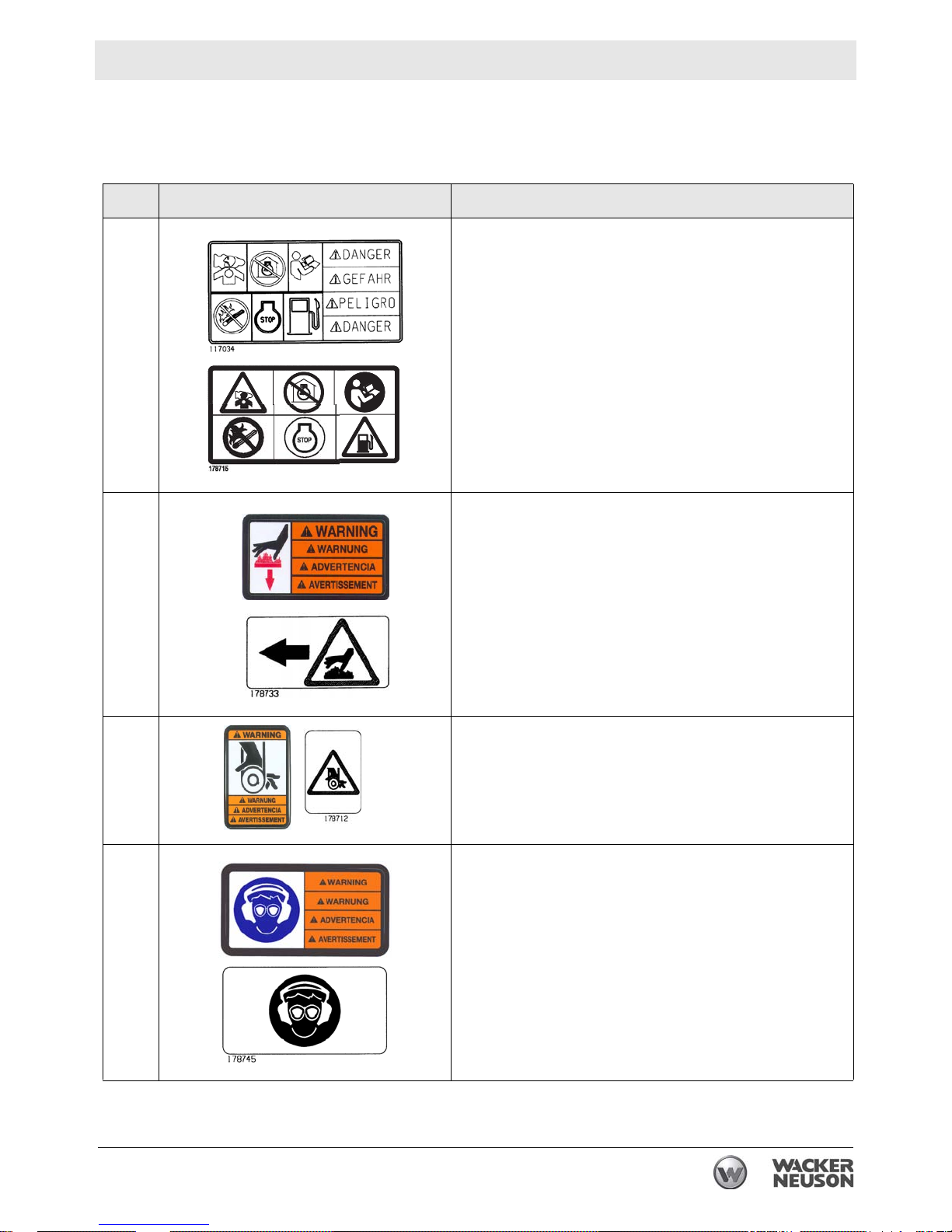
2.2 Label Meanings
Label Meaning
A
B
DANGER!
Asphyxiation hazard.
Engines emit carbon monoxide.
Do not run the machine indoors or in an enclosed
area unless adequate ventilation, through such items
as exhaust fans or hoses, is provided.
Read the Operator’s Manual. No sparks, flames, or
burning objects near the machine. Stop the engine
before refueling.
WARNING!
Hot surface!
C
D
wc_si000505gb.fm 15
WARNING!
Hand injury if caught in moving belt.
Always replace beltguard.
WARNING!
Always wear hearing and eye protection when operating
this machine.
Page 16
Labels CT24-4A
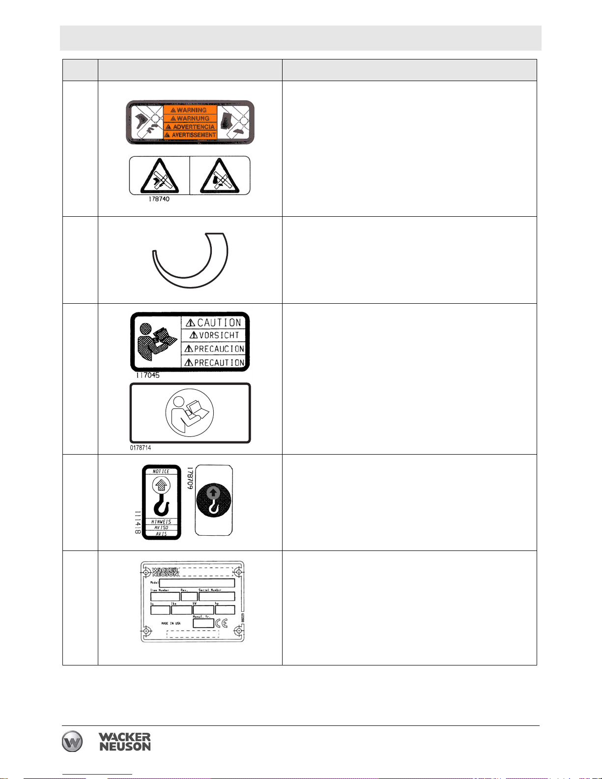
Label Meaning
E
F
G
WARNING!
Cutting hazard. Always replace blade guard!
Variable speed throttle
CAUTION!
Read and understand the supplied Operator’s Manual
before operating this machine. Failure to do so
increases the risk of injury to yourself and others.
H
NOTICE
Lifting point.
A nameplate listing the model number, item number,
revision number, and serial number is attached to each
unit. Please record the information found on this plate
so it will be available should the nameplate become lost
or damaged. When ordering parts or requesting service
information, you will always be asked to specify the
model number, item number, revision number, and
serial number of the unit.
16 wc_si000505gb.fm
Page 17

CT24-4A Labels
3
2
1
7
6
5
4
3
2
1
172847
Label Meaning
This machine may be covered by one or more patents.
Label Meaning
J
111
172847
2
3
4
5
To start the machine:
1. Open the fuel flow valve.
2. Close the choke.
3. Push or turn engine switch to ON position.
4. Place throttle in the IDLE position.
5. Engage operator present lever.
6. Pull the rewind starter.
7. Open the choke.
To stop the machine:
1. Release operator present lever.
6
7
1
2
3
2. Push or turn engine switch to OFF position.
3. Close the fuel flow valve.
wc_si000505gb.fm 17
Page 18
Lifting and Transporting CT 24-230E
3 Lifting and Transporting
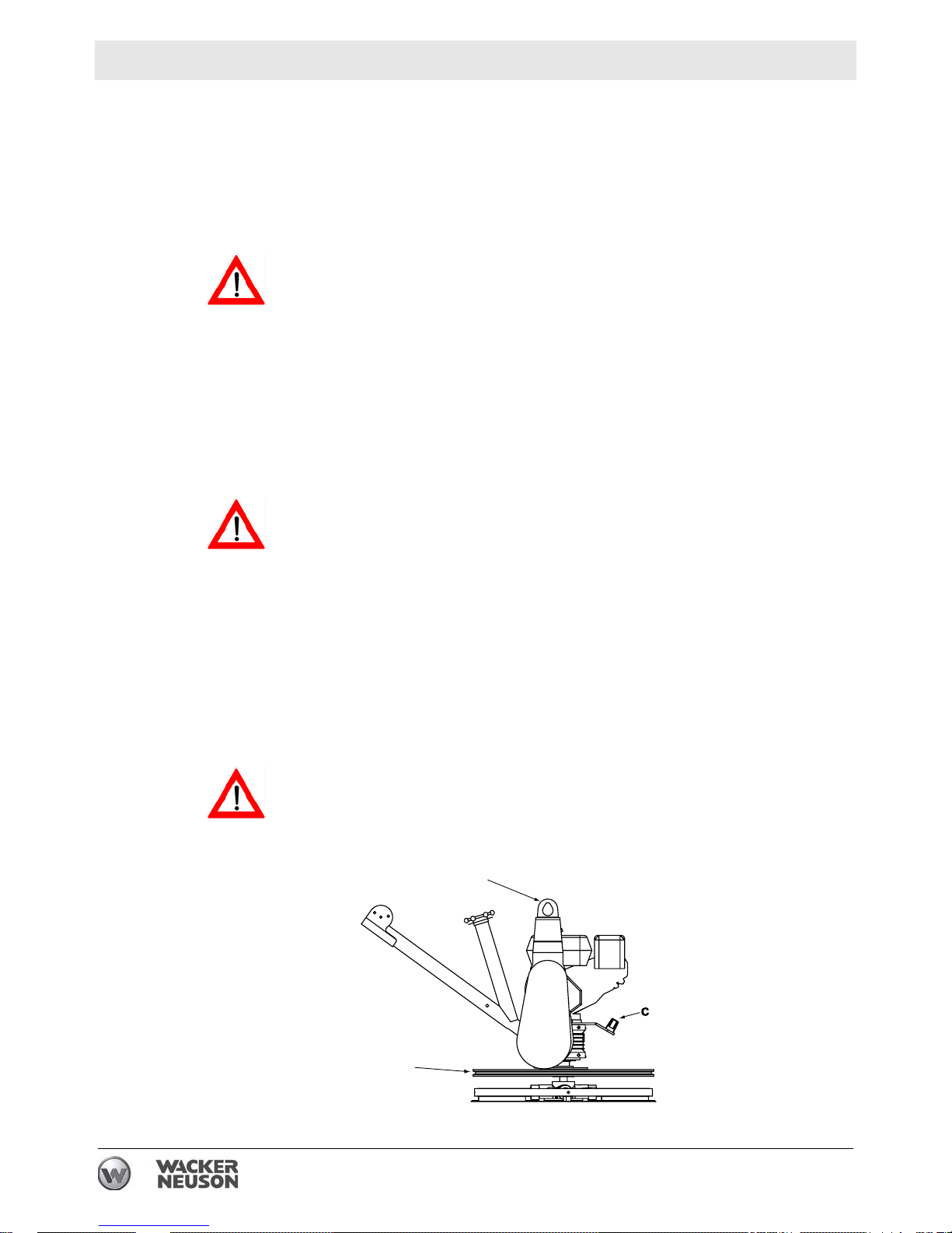
3.1 Lifting the Machine
See Graphic: wc_gr004390
NEVER lift the machine solely by the handle. The component may fail,
causing the machine to fall, possibly injuring bystanders.
WARNING
See Technical Data for the weight of the machine.
To lift the machine manually:
3.1.1 Stop machine.
3.1.2 Obtain a partner and plan the lift.
3.1.3 Balance the weight between the partners and lift the machine by the
guard ring (a).
To reduce risk of back injury while lifting, keep your feet flat on ground
and shoulder width apart. Keep your head up and back straight.
WARNING
To lift the machine mechanically:
3.1.4 Stop machine.
3.1.5 See Dimensions and Weight for weight of machine and be sure that
lifting device(s) can safely lift the weight.
3.1.6 Attach hook, harness, or cable to the lifting bracket (b) on machine as
shown and lift as desired.
Do not lift the trowel overhead with a float pan attached, as the pan
could fall off and strike personnel working in the vicinity.
WARNING
b
a
wc_gr004390
18 wc_tx001520gb.fm
Page 19

CT 24-230E Lifting and Transporting
3.2 Transporting
Required
• Transport vehicle capable of handling the weight of the trowel
• Suitable ropes or chains
Procedure
Follow the procedure below to tie down and transport the machine.
3.2.1 Lift the trowel onto the transport vehicle.
3.2.2 Position the handle so that it does not protrude outside the footprint of
the transport vehicle.
3.2.3 Connect the ropes/chains to the ring guard of the trowel as follows.
a. Connect them as low on the ring guard as possible to minimize
stress on the gearbox output shaft.
b. Use a crossing pattern as shown.
3.2.4 Connect the ropes/chains to the transport vehicle. Do not overtighten
them.
Result
The machine is now ready to be transported.
wc_tx001520gb.fm 19
Page 20

Operation CT 24-4A
4 Operation
4.1 Preparing for First Use
Preparing for first use
To prepare your machine for first use:
4.1.1 Make sure all loose packaging materials have been removed from the
machine.
4.1.2 Check the machine and its components for damage. If there is visible
damage, do not operate the machine! Contact your Wacker Neuson
dealer immediately for assistance.
4.1.3 Take inventory of all items included with the machine and verify that
all loose components and fasteners are accounted for.
4.1.4 Attach component parts not already att a ched.
4.1.5 Add fluids as needed and applicable, including fuel, engine oil, and
battery acid.
4.1.6 Move the machine to its operating location.
4.2 New Machine Set-up
Trowels are shipped from the factory with the handle folded. Follow
instructions on Installing Blades and Unfolding Handle when setting up
new machines or when installing new blades.
4.3 Recommended Fuel
The engine requires regular grade unleaded gasoline. Use only fresh,
clean gasoline. Gasoline containing water or dirt will damage fuel
system. Consult engine owner’s manual for complete fuel
specifications.
20 wc_tx001521gb.fm
Page 21

CT 24-4A Operation
4.4 Installing Blades
See Graphic: wc_gr004417
There are two types of blades available for the trowels. Float pans are
large “pizza pan” style blades, which hook on over finish blades. Float
blades are used in the earliest stages of work, and are not pitched.
Finish blades are used in the final stages of working, and are
progressively pitched to burnish the concrete.
Note: Trowel blades must NOT be interchanged, i.e., do NOT put
larger diameter blades on a smaller diameter trowel.
4.4.1 Secure blades to trowel arms with screws (b). Dip threads of screws in
grease prior to installation. This will prevent concrete from cementing
the screws in place and will make removal of the blades easier later on.
4.4.2 Plug the remaining threaded holes in the blade brace with plastic plugs
(c) to prevent them from filling with concrete.
Do not lift the trowel overhead with a float pan attached, as the pan
could fall off and strike personnel working in the vicinity.
WARNING
c
b
wc_gr004417
wc_tx001521gb.fm 21
Page 22

Operation CT 24-4A
4.5 Unfolding Handle
See Graphic: wc_gr004384
On new machines the pipe handle comes folded with the following
components attached: Twist pitch control (a), Operator Present Lever
(b), throttle lever (c), hinge pin (d), and adjustable lever (e).
To unfold and secure the pipe handle assembly:
4.5.1 While holding the hinge pin, unscrew and remove the adjustable lever
and metal washer.
4.5.2 Remove the hinge pin.
4.5.3 Straighten the pipe handle and re-insert the hinge pin.
4.5.4 Replace the metal washer over the threaded end of the hinge pin, and
re-install the adjustable lever.
4.5.5 Tighten the adjustable lever to lock the pipe handle in its fully opened
position.
22 wc_tx001521gb.fm
Page 23

CT 24-4A Operation
4.6 Controls
See Graphic: wc_gr004384
Ref. Description Ref. Description
a Twist pitch control d Hinge pin
b Operator Present Lever e Adjustable lever
c Throttle lever
4.7 Operator Present Lever
See Graphic: wc_gr004384
When the Operator Present Lever (b) is released, the engine will shut
off.
Watch for spinning blades! Even after the engine has shut off, the
trowel blades will continue to rotate. To avoid severe injury, keep feet
WARNING
wc_tx001521gb.fm 23
and fingers away from the ring guard until the blades have come to a
complete stop.
Page 24

Operation CT 24-4A
4.8 Before Starting
Before starting trowel, check the following:
• oil level in engine
• oil level in gearbox
• fuel level
• condition of air filter
• condition of fuel lines
• condition of trowel arms and blades
• condition of ring guard
• label descriptions
• adjustable lever is tight
4.9 To Start
See Graphic: wc_gr004384, wc_gr001098
4.9.1 Open fuel valve by moving lever to the right (g1).
Note: If engine is cold, move choke lever to closed position (i1). If
engine is hot, set choke to open position (i2).
4.9.2 Turn engine switch to “ON” (h1).
4.9.3 Move the throttle lever to the idle position (c1).
Start engine with throttle in the IDLE position. If the engine is started
when the throttle is not in the IDLE position, the trowel blades may spin
unexpectedly and cause injury.
WARNING
4.9.4 Squeeze and hold the Operator Present Lever (b).
4.9.5 Pull starter rope (j).
Do not place foot on the ring guard when starting the engine, as severe
injury can occur if foot slips through the ring guard as the blades start
WARNING
to spin.
Note: If the engine oil is low, the engine will not start. If engine does
not start, check the oil level and add oil as needed.
4.9.6 Open choke as engine warms (i2).
4.9.7 Open throttle (c2) to operate trowel. Adjust blade RPM with throttle
speed to suit conditions.
24 wc_tx001521gb.fm
Page 25

CT 24-4A Operation
g1
g2
4.10 To Stop
See Graphic: wc_gr004384, wc_gr001098
4.10.1 Reduce engine RPM to idle by moving the throttle lever to idle position
4.10.2 Release the Operator Present Lever (b).
4.10.3 Turn engine switch to “OFF” (h2).
4.10.4 Close fuel valve by moving lever to the left (g2).
(c1).
h2
h1
i1
i2
j
wc_gr001098
wc_tx001521gb.fm 25
Page 26

Operation CT 24-4A
4.11 Position of the Operator
Safe and efficient use of this machine is the operator’s responsibility .
Full control of the machine is not possible unless the operator
maintains the proper working position at all times.
While operating this machine the operator must:
• stand or walk behind the machine, facing forward
• have both hands on the control handle
• guide the motion of the trowel by applying downward pressure to
the control handle
4.12 Operation
See Graphic: wc_gr004418
ALWAYS test the function of the Operator Present Lever before
operating the trowel. DO NOT operate the trowel if the Operator
WARNING
Present Lever is not functioning properly.
Choose correct blade type and attach blades to trowel arms.
Note: When operating on soft concrete, do not let trowel stand in one
spot too long. Always lift trowel from slab when operation is complete.
Note: “Left” and “Right” references are made from the operator's
position.
4.12.1 Start engine and engage blades by increasing engine speed. Set
speed with throttle control on handle bar to appropriate speed for job
conditions.
4.12.2 To move trowel forward twist handle clockwise (a).
4.12.3 To move backward twist handle counterclockwise (b).
4.12.4 To move to the left lift up slightly on the handle (c).
4.12.5 To move to the right press down slightly on the handle (d).
4.12.6 Clean trowel after each use to remove concrete splatter.
Allow the muffler to cool before cleaning or servicing the machine. A
hot muffler could ignite the fuel and start a fire.
WARNING
Personnel other than the trowel operator should not be allowed in the
work area, as severe injury can occur from contact with operating
WARNING
trowel blades.
26 wc_tx001521gb.fm
Page 27

CT 24-4A Operation
Do not attempt to clean, service or perform adjustments on the trowel
while it is running.
a
c
b
4.13 Emegency Shutdown Procedure
Procedure
If a breakdown or accident occurs while the machine is operating,
follow the procedure below:
4.13.1 Stop the engine.
4.13.2 Close the fuel valve
d
wc_gr004418
4.13.3 Remove the machine from the job site using correct lifting techniques.
4.13.4 Clean concrete from the blades and the machine.
4.13.5 Contact the rental yard or machine owner for further instructions.
wc_tx001521gb.fm 27
Page 28

Operation CT 24-4A
4.14 Pitch Adjustment
See Graphic: wc_gr004108
To adjust blade pitch (angle):
A = Twist pitch: turn the pitch adjusting knob (a) clockwise to increase
pitch and counterclockwise to decrease pitch.
Ref. B = Working condition of concrete C = Suggested working pitch
1 Wet surface working stage Flat (no pitch)
2 Wet to plastic working stage Slight pitch (5°)
3 Plastic working stage Additional pitch (10°)
4 Semi-hard working stage to
hard finishing stage (burnishing)
Maximum pitch (15°)
28 wc_tx001521gb.fm
Page 29

CT 24-4A Maintenance
5 Maintenance
5.1 Periodic Maintenance Schedule
The table below lists basic machine and engine maintenance. Tasks
designated with check marks may be performed by the operator.
Tasks designated with square bullet points require special training
and equipment.
Refer to the engine owner’s manual for additional information.
Check fuel level.
Check engine oil level.
Inspect fuel lines.
Inspect air filter. Replace as needed.
Check external hardware.
Clean trowel after each use to remove
concrete splatter.
Grease blade arms as needed.
Clean air cleaner elements.
Change engine oil.
Check drive belt.
Daily
3
3
3
3
3
After
first
20 hrs.
Every
50
hrs.
Every
100
hrs.
Every
300
hrs.
Clean sediment cup.
Check and clean spark plug.
Check and adjust valve clearances.
wc_tx001522gb.fm 29
Page 30

Maintenance CT 24-4A
5.2 Engine Oil
Voir Dessin : wc_gr004132
5.2.1 Drain oil while the engine is still warm.
5.2.2 Remove the oil fill plug (a) and drain cap (b) to drain oil.
Note: In the interests of environmental protection, place a plastic sheet
and a container under the machine to collect any liquid which drains
off. Dispose of this liquid in accordance with environmental protection
legislation.
5.2.3 Install drain cap.
5.2.4 Fill the engine crankcase with recommended oil up to the level of the
plug opening (c). See Technical Data for oil quantity and type.
5.2.5 Install the oil filler plug.
30 wc_tx001522gb.fm
Page 31

CT 24-4A Maintenance
5.3 Air Cleaner
Voir Dessin : wc_gr000025
The engine is equipped with a dual element air cleaner. Service air
cleaner frequently to prevent carburetor malfunction.
NOTICE: NEVER run engine without air cleaner. Severe engine
damage will occur.
NEVER use gasoline or other types of low flash point solvents for
cleaning the air cleaner. A fire or explosion could result.
WARNING
To service:
5.3.1 Remove air cleaner cover (a). Remove both elements and inspect
them for holes or tears. Replace damaged elements.
5.3.2 Wash foam element (b) in solution of mild detergent and warm water.
Rinse thoroughly in clean water. Allow element to dry thoroughly. Soak
element in clean engine oil and squeeze out excess oil.
5.3.3 Tap paper element (c) lightly to remove excess dirt. Replace paper
element if it appears heavily soiled.
wc_tx001522gb.fm 31
Page 32

Maintenance CT 24-4A
5.4 Spark Plug
Voir Dessin : wc_gr000028
Clean or replace the spark plug as needed to ensure proper operation.
Refer to your engine operator’s manual.
The muffler becomes very hot during operation and remains hot for a
while after stopping the engine. Do not touch the muffler while it is hot.
WARNING
Note: Refer to section “Technical Data” for the recommended spark
plug type and the electrode gap setting.
5.4.1 Remove the spark plug and inspect it.
5.4.2 Replace the spark plug if the insulator is cracked or chipped.
5.4.3 Clean the spark plug electrodes with a wire brush.
5.4.4 Set the electrode gap (a).
5.4.5 Tighten the spark plug securely.
NOTICE: A loose spark plug can become very hot and may cause
engine damage.
32 wc_tx001522gb.fm
Page 33

CT 24-4A Maintenance
5.5 Cleaning Sediment Cup
Voir Dessin : wc_gr000029
5.5.1 Turn the fuel valve off.
5.5.2 Remove the sediment cup (a) and the O-ring (b).
5.5.3 Wash both thoroughly in a nonflammable solvent. Dry and reinstall
them.
5.5.4 Turn the fuel valve on and check for leaks.
wc_tx001522gb.fm 33
Page 34

Maintenance CT 24-4A
5.6 Adjusting Idle Speed
Voir Dessin : wc_gr001122
Remove the drive belt before making any adjustment to the carburetor.
See Belt Replacement. The blades will engage unless the belt is
WARNING
5.6.1 Start the engine and allow it to warm up to normal operating
5.6.2 Turn the throttle stop screw (a) in to increase speed, out to decrease
removed from the machine.
Adjust engine to the no load or idle speed per the Technical Data.
temperature.
speed. Make sure the throttle lever is touching the stop screw before
measuring rpm.
a
wc_gr001122
34 wc_tx001522gb.fm
Page 35

CT 24-4A Maintenance
5.7 Carburetor Adjustment
Voir Dessin : wc_gr0001061
Remove the drive belt before making any adjustment to the carburetor.
See Belt Replacement. The blades will engage unless the belt is
WARNING
removed from the machine.
The pilot screw (a) is fitted with a limiter cap to prevent excessive
enrichment of the air-fuel mixture in order to comply with emission
regulations. The mixture is set at the factory and no adjustment should
be necessary. Do not attempt to remove the limiter cap. The limiter cap
cannot be removed without breaking the pilot screw.
a
wc_gr001061
wc_tx001522gb.fm 35
Page 36

Maintenance CT 24-4A
5.8 Belt Replacement
Voir Dessin : wc_gr004429
The trowel is equipped with a self-adjusting clutch. This clutch
automatically tightens the belt and compensates for belt wear. Replace
the belt if the clutch can no longer tighten belt enough to engage
gearbox without slipping.
To replace the drive belt:
5.8.1 Disconnect the spark plug lead.
To avoid accidental starting of the engine, always disconnect the spark
plug lead before working on machine.
WARNING
5.8.2 Loosen the screws (d) and remove the belt guard (c).
5.8.3 Slowly turn the pulley (b) and roll the belt (a) off.
Note: The clutch and the pulley are aligned at the factory and neither
should be removed during belt replacement.
5.8.4 Install the new belt.
5.8.5 Reattach the belt guard with washers and screws. Torque the screws
to 5 Nm (3.7 ft.lbs.).
a
c
b
d
wc_gr004429
36 wc_tx001522gb.fm
Page 37

CT 24-4A Maintenance
5.9 Trowel Lubrication
Voir Dessin : wc_gr0014389
Grease trowel arms (b) with Shell Alvania RL2 grease or equivalent.
Oil the pitch control cable and other parts of trowel on an as needed
basis.
Oil in the gearbox should not require replacement unless it was
drained to service gearbox. Check quantity through plug (a) located on
side of gearbox. Oil level should be to bottom of the plug threads. See
Technical Data for oil quantity and type.
a
b
wc_gr004389
wc_tx001522gb.fm 37
Page 38

Maintenance CT 24-4A
5.10 Storage
If trowel is being stored for more than 30 days:
• Change engine oil.
• Drain fuel from engine.
• Remove spark plug and pour 15 ml (½ ounce) of SAE 30 engine
oil into the cylinder. Replace spark plug and crank engine to distribute oil. Refer to engine manual.
• Clean dirt from cylinder, cylinder head fins, blower housing, rotat-
ing screen, and muffler areas.
• To save space, place handle in its storage position.
• Cover trowel and engine and store in a clean, dry area.
38 wc_tx001522gb.fm
Page 39

CT 24-4A Troubleshooting
6 Troubleshooting
6.1 Basic Troubleshooting
Problem / Symptom Reason / Remedy
Trowel does not develop full
speed.
Engine runs;
poor trowel operation.
Engine does not start or runs
erratically.
• Remove deposits built up in engine cylinder and
engine head.
• Engine speed too low. Adjust speed.
• Clean or replace air filter.
• Clean debris from moving parts and trowel blades.
• In cold weather, warm engine in idle 3 or 4 minutes.
• Check throttle lever and cable for proper operation.
• Check drive belt for wear or damage.
• Check clutch for wear or damage.
• Clean debris from moving parts and trowel arms.
• Check fuel level. Open fuel valve.
• Clean air filter.
• Check/replace spark plug.
• Check in-line fuel filter.
• Check engine oil level.
• Check engine stop button.
• Check that throttle is in idle position when starting
machine.
Trowel handle tends to rotate
when idling.
wc_tx001523gb.fm 39
• Check engine idle speed. (It may be too high).
• Belt alignment may be off.
Page 40

Technical Data CT 24-4A
C
E
D
A
B
7 Technical Data
7.1 Dimensions and Weight
C
E
D
B
A
wc_gr004383
Dimensions mm (in.) Dry Weight kg (lbs.)
A 1537 (60-1/2) without float pan 64 (141)
B 610 (24) with float pan 70 (153)
C 1003 (39-1/2) Full Wet (Operating) Weight kg (lbs.)
D 940 (37) without float pan 66 (145)
E 788 (31) with float pan 71 (157)
40 wc_td000219gb.fm
Page 41

CT 24-4A Technical Data
7.2 Engine
Engine Power Rating
Net power rating per SAE J1349. Actual power output may vary due to
conditions of specific use.
Item No.
Engine make
Engine model
Max. rated power @
rated speed
Spark plug
Electrode gap
Engine speed - operating
Engine speed - idle
Clutch engagement
Valve clearance (cold)
intake:
exhaust:
Air cleaner
Engine lubrication
Engine oil capacity
Fuel
Fuel tank capacity
Running time
kW (Hp)
mm (in.)
rpm
rpm
rpm
mm (in.)
type
oil grade
l (oz.)
type
l (qts.)
hr.
CT 24-4A
0620105, 0620849
Engine
Honda
GX 120 UT1 QX2
2.6 (3.5) @ 3600rpm
NGK BPR6ES / Denso W20EPR-U
0.7 – 0.8 (0.028 – 0.031)
3800±100
1450±100
1800
0.15 (0.006)
0.20 (0.008)
Dual element
SAE 10W30 API SJ or SL
0.6 (20)
Regular unleaded gasoline
2.5 (2.64)
2
wc_td000219gb.fm 41
Page 42

Technical Data CT 24-4A
7.3 Trowel
Model Item No.
Trowel
Diameter*
mm (in.)
Number
of
Blades
Gear Box
Lubrication
type/ml (oz.)
Speed
Range
rpm
Trowel
Mobilgear
SH 220
CT 24-4A 0620105 610 (24) 4
Synthetic,
E-Series
90–141 0–15
Approx.
620 (21)
*Trowel blades must NOT be interchanged, i.e., do NOT put larger diameter blades on a smaller
diameter trowel.
Pitch
Range
degrees
42 wc_td000219gb.fm
Page 43

CT 24-4A Technical Data
7.4 Sound and Vibration Data
The required sound specification, Paragraph 1.7.4.f of 89/392/EEC
Machinery Directive, is:
• the sound pressure level at operator’s location (L
• the guaranteed sound power level (L
) = 83 dB(A)
WA
) : 97 dB(A)
pA
These sound values were determined according to ISO 3744 for the
sound power level (LWA) and ISO 6081 for the sound pressure level
(LpA) at the operator’s location.
ISO 5349 Part 1 Annex F states, “The vibration characteristics of a
vibrating tool can be highly variable. It is therefore important that the
range of vibration conditions associated with different workpieces,
materials, working conditions, methods of use of the tool, and
exposure duration patterns be reported.”
• The average hand and arm vibration value obtained for the entire
operating rpm range is 6.9 m/s2.
• The maximum hand and arm vibration value obtained within the entire
operating rpm range is 8.4 m/s2.
• The minimum hand and arm vibration value obtained within the entire
operating rpm range is 6.0 m/s2.
The sound and vibration specifications were obtained on wetted and
cured concrete using the most commonly sold machine configurations.
Vibration values will vary depending on throttle position, operating
conditions, and handle option.
7.4.1 HAV Uncertainties
Hand-transmitted vibration was measured per ISO 5349-1. This
measurement includes an uncertainty of 1.5 m/sec2 .
wc_td000219gb.fm 43
Page 44

Page 45

Page 46

SAFETY ALERT SYMBOL
This Safety Alert Symbol means
ATTENTION is required!
The Safety Alert Symbol identifies important safety
messages on machines, safety signs, in manuals
or elsewhere. When you see this symbol, be alert
to the possibility of personal injury or death. Follow
the instructions in the safety message.
Why is SAFETY important to YOU?
3 BIG REASONS
• Accidents KILL or DISABLE
• Accidents COST
• Accidents CAN BE AVOIDED
1
NOTICE OF COPYRIGHT PROTECTION
AEM Safety Manuals are protected as a copyrighted work with
ownership duly registered with the Copyright Office,
Washington, D.C. Any reproduction, translation, decompiling or
other use of an AEM Safety Manual, or portion thereof, or the
creation of derivative works based on an AEM Safety Manual,
without the prior written approval of AEM is expressly prohibited.
Copyright infringement can result in civil and criminal sanctions,
damages and other penalties being imposed.
Copyright © 2003 – Association of Equipment Manufacturers
!
Trowel.qxd 11/24/04 10:18 AM Page 1
U.S. Department of Labor publishes Safety and
Health Regulations and Standards under the
authority of the Occupational Safety and Health Act
for the General Construction and Mining Industries.
Its address is: U.S. Department of Labor,
Washington, DC 20210 (www.OSHA.gov and
www.MSHA.gov).
ANSI – American National Standards Institute, c/o
The American Society of Mechanical Engineers,
United Engineering Center, 345 East 47th Street,
New York, NY 10017 (www.ANSI.org).
ISO – International Standards Organization,
1, rue de Varembe Case postale 56, CH-1211
Geneva 20, Switzerland (www.ISO.ch).
SAE – Society of Automotive Engineers, Inc.,
400 Commonwealth Drive, Warrendale, PA 15096,
publishes a list, “Operator Precautions” SAE J153
MAY 87 (www.SAE.org).
AEM – Association of Equipment Manufacturers,
111 East Wisconsin Avenue, Milwaukee, WI 53202
(www.AEM.org).
WORD OF EXPLANATION
2
The following is a partial list of reference material on safe operating practices:
Trowel.qxd 11/24/04 10:18 AM Page 2
Page 47

3
TABLE OF CONTENTS
Page
WORD OF EXPLANATION ................................................................2
FOREWORD........................................................................................4
A WORD TO THE USER ....................................................................5
FOLLOW A SAFETY PROGRAM ......................................................6
PREPARE FOR SAFE OPERATION ..................................................7
START SAFELY ................................................................................11
WORK SAFELY ................................................................................13
SHUT DOWN SAFELY ......................................................................15
LOAD AND UNLOAD SAFELY ........................................................16
PERFORM MAINTENANCE SAFELY ..............................................17
TEST YOUR KNOWLEDGE..............................................................22
A FINAL WORD TO THE USER........................................................23
Trowel.qxd 11/24/04 10:18 AM Page 3
This safety manual is intended to point out some of
the basic situations which may be encountered
during the normal operation and maintenance of
your walk-behind or ride-on concrete power trowel
and to suggest possible ways of dealing with these
conditions.
Additional precautions may be necessary,
depending on application and attachments used
and conditions at the work site or in the
maintenance area.
The trowel manufacturer has no direct control over
machine application, operation, inspection,
lubrication, or maintenance. Therefore, it is your
responsibility to use good safety practices in these
areas.
Do not use the trowel for any purpose other than its
intended purposes or applications.
The information provided in this manual
supplements the specific information about your
machine and its application that is contained in the
manufacturer’s manual(s).
Other information which may affect the safe
operation of your machine may be displayed on
safety signs, or in insurance requirements,
employer’s safety programs, safety codes, local,
state/provincial, and federal laws, rules, and
regulations.
If you do not understand any of this information, or
if errors or contradictions seem to exist, consult
with your supervisor before operating your trowel!
IMPORTANT: If you do not have the
manufacturer’s manual(s) for your particular
machine, get a replacement manual from your
employer, equipment dealer, or manufacturer of
your machine. Keep this safety manual and the
manufacturer’s manual(s) accessible to the
operator and maintenance personnel.
FOREWORD
4
Trowel.qxd 11/24/04 10:18 AM Page 4
Page 48

Remember that YOU are the key to safety. Good
safety practices not only protect you but also
protect the people around you. It is your
responsibility to study this manual and the
manufacturer’s manual(s) for your specific machine
before operating your machine. Make them a
working part of your safety program. Keep in mind
that this safety manual is written for concrete power
trowels only. Practice all other usual and customary
safe working precautions, and above all –
REMEMBER – SAFETY IS UP TO YOU
YOU CAN PREVENT SERIOUS
INJURY OR DEATH
A WORD TO THE USER
5
Trowel.qxd 11/24/04 10:18 AM Page 5
EQUIPMENT/CLOTHING
Consult your supervisor for specific instructions on
a job, and the personal safety equipment required.
For instance, you may need:
• Hard Hat
• Heavy Gloves
• Eye Protection
• Ear Protectors
• Safety Shoes
• Dust Mask or Respirator
Do not wear loose clothing or any accessory –
flopping cuffs, dangling neckties and scarves, or
jewelry – that can catch in moving parts.
DUST PRECAUTION
Some dust created by construction activities may
cause silicosis or respiratory harm.
Your risk of exposure varies depending on how
often you do this type of work. To reduce your risk,
work in a well ventilated area, use a dust control
system, and wear approved personal safety
equipment such as a dust/particle respirator
designed to filter out microscopic particles.
FOLLOW A SAFETY PROGRAM
6
Trowel.qxd 11/24/04 10:18 AM Page 6
Page 49

LEARN TO BE SAFE
• Read the operator’s
manual. If one has not
been provided, get one and
study it before operating
the equipment.
• Learn the location and
understand the functions of
all controls before
attempting to operate the
equipment.
• Know the meaning of all identification symbols on
the controls and gauges.
• Check to determine that the manufacturer’s
furnished safety warning labels are securely
attached to the trowel and all warnings can
clearly read. Replace labels and decals if they
are missing or become worn or unreadable.
• Know the location and type of emergency shutdown control the trowel is equipped with.
• Never start or operate the trowel without
protective guards and panels in place.
• Know the capabilities and limitations of the
trowel.
SAFETY DEVICES
Know what safety devices your trowel is equipped
with … and see that each item is securely in place
and in operating condition.
For example:
• Emergency stop switch or other “Shut-Down”
devices
• Guards, Shields & Panels
• Alarms or Warning Lamps
• Drain Covers, Plugs, and Caps
• Pressure Relief Devices
• Lights
7
PREPARE FOR SAFE OPERATION
Trowel.qxd 11/24/04 10:18 AM Page 7
PRE-OPERATIONAL CHECKS
Walk around the trowel. Carefully inspect for
evidence of physical damage, such as cracks,
bends, or deformation of plates and welds. Check
for loose, broken or missing parts on the trowel,
including brackets, vibration isolators, nuts and
bolts. Hardware should be replaced with original
equipment manufacturer’s (OEM) parts, and should
be properly tightened to the manufacturer’s
recommendations.
Remove all trash and debris from the trowel. Make
sure oily rags, leaves, or other flammable material
are removed and not stored on the trowel. Avoid
potential fire hazards!
Clean all oil or grease
from operator areas such
as control handles, foot
pedals, or platforms to
prevent slipping.
Check for fuel, oil, and
hydraulic fluid leaks. All
leaks must be corrected
before the trowel is
operated.
Inspect all hydraulic hoses for cracks or signs of
wear and replace if necessary. Secure all caps and
filler plugs for all systems.
Always use a a flashlight or shielded trouble light
when checking for leaks – never use an open
flame. Never check for hydraulic leaks with your
hand. Hydraulic systems are under high pressure
and leaks in these systems can penetrate the skin
which can result in serious injury or even death.
Always use a piece of cardboard or wood when
looking for hydraulic leaks.
Be sure the trowel is
properly lubricated. See
that the fuel, lubricating oil,
coolant and hydraulic
reservoirs are filled to the
proper levels with the
correct fluids according to
the manufacturer’s
instructions and
recommendations.
8
PREPARE FOR SAFE OPERATION
Trowel.qxd 11/24/04 10:18 AM Page 8
Page 50

FIRE PREVENTION
Always stop the engine and allow it to cool before
refueling.
Never refuel –
• When engine is running
• Near open flame or sparks
• While smoking
• In poorly ventilated areas
Never overfill fuel tanks or fluid reservoirs. In the
event of a fuel spill, do not attempt to start the
engine until the fuel residue has been completely
wiped up, and the area surrounding the engine is
dry. Replace fuel cap securely after refueling.
Inspect electrical wiring for damage or wear.
Batteries produce explosive gas. Keep open flame
or sparks away.
In case of accident or fire, be ready to act quickly,
yet calmly. Do not panic. Knowing ahead of time
where to locate a first aid kit, fire extinguisher, or to
get assistance will help should an emergency
situation come up.
CHECK THE WORK AREA
Learn – beforehand –
as much about your
working area as
possible.
Be observant of other
workers, bystanders
and other machinery
in the area. Keep all
unauthorized,
untrained people and
children out of the
area while the trowel
is in operation.
9
PREPARE FOR SAFE OPERATION
Trowel.qxd 11/24/04 10:18 AM Page 9
CHECK THE AREA
Thoroughly check the area for unusual or
dangerous conditions, such as tools, or items that
may damage the trowel or be propelled by the
trowels rotating blades. Note where pipes and
forms are located. Locate and mark protrusions
(rebar, anchor bolts, floor drains, etc.) in the
concrete.
GETTING ON AND OFF A RIDE-ON TROWEL
If operating a ride-on trowel, mount and dismount
carefully. Use the steps and hand holds provided.
Do not use control levers as hand holds and never
use guard rings as steps. Watch for surfaces that
may be slippery. Never jump off a ride-on trowel.
OPERATING ON AN ELEVATED DECK
(MULTI-STORY OPERATION)
Consult local/state regulations before you operate
equipment on an elevated deck. If operating on an
elevated deck, ensure perimeter safety cabling of
proper size and strength is in place. Do not operate
the trowel close to the edge of the deck.
TRANSPORTING THE TROWEL
Never transport the trowel with float pans attached
unless safety catches are used and are specifically
cleared for such transport by the manufacturer.
Under no circumstances hoist the trowel more than
three feet off the ground with float pans attached.
Always consult the manufacturer’s operation
manual for specific information on transporting the
trowel.
10
PREPARE FOR SAFE OPERATION
Trowel.qxd 11/24/04 10:18 AM Page 10
Page 51

START CORRECTLY – START SAFELY
Before starting, check for proper functioning of all
operation and shutdown controls. Check all
controls to be sure they are in the correct startup
position. Know the proper starting procedure for
your trowel. Follow the manufacturer’s operational
instructions.
WALK-BEHIND TROWELS
• Ensure that the operator is familiar with the
trowel and is trained on its operation.
• Ensure the operator is well rested, not fatigued,
is alert, and not impaired in any way
(medications, drugs, alcohol, etc.).
• Do not start or operate the trowel if the drive train
will not disengage. Centrifugal force between the
trowel and surface when starting can cause
uncontrolled handle movement that can cause
serious injury. The handle must not move while
pulling the engine recoil starter.
• Visually check to be sure that the blades are free
of obstructions and the area is clear for
operation.
• For trowels that use this feature, ensure that the
emergency stop switch is in the ON position.
• Move the throttle to the idle position.
• Switch the engine ON/OFF switch to the ON
position.
• Never place your foot on the ring guard when
starting the engine or severe injury can occur if
your foot slips through the ring guard as the
blades start to spin.
• While firmly holding the handle with one hand,
start the engine following the guidelines in the
engine manufacturer’s instruction manual.
• Hold the handle bar firmly with both hands while
the trowel is “throttled-up”.
• If control of the trowel is lost, stay clear and do
not attempt to regain control until the trowel has
stopped moving. Depending on the engine
speed, the trowel handle can swing around
before it stops completely.
• You are ready to operate the trowel!
11
START SAFELY
Trowel.qxd 11/24/04 10:18 AM Page 11
RIDE-ON TROWELS
• Ensure that the operator is familiar with the
trowel and is trained on its operation.
• Ensure the operator is well rested and not
fatigued, is alert, and not impaired in any way
(medications, drugs, alcohol, etc.).
• Adjust the seating if necessary and get into a
comfortable position where all controls are
accessible.
• Visually check to be sure that the blades are free
of obstructions and the area is clear for
operation.
• Start the trowel following the instructions in the
engine manufacturer’s operation manual. For
diesel powered trowels, follow the instructions for
glow plug and cold start operation.
• Observe any gauges and warning lights to
ensure they are functioning and their readings
are within the manufacturer’s normal operating
range.
• Check operation of controls. Make certain they
operate properly.
• You are ready to operate the trowel!
12
START SAFELY
Trowel.qxd 11/24/04 10:18 AM Page 12
Page 52

SAFE WORKING PROCEDURES
DANGER – CARBON MONOXIDE
Exhaust from the engine contains
poisonous carbon monoxide gas
that is not easily detected as it is
colorless and odorless. Exposure
to carbon monoxide can cause
loss of consciousness and may
lead to death! Do not operate
your trowel indoors or in an enclosed area unless
adequate ventilation is provided. Ensure that
permissible carbon monoxide levels are monitored
and not exceeded.
OTHER PRECAUTIONS
• Never leave the trowel unattended while it is
running.
• Always keep clear of rotating or moving parts.
• Never use additional weights other than the
weights recommended by the manufacturer. The
use of unauthorized weights could lead to
personal injury or damage to the trowel.
• Never fill the fuel tank while the engine is
running. Turn the engine off and allow it to cool
before refueling.
• The muffler, exhaust pipes and
other engine parts will become
hot during operation and will
remain hot for a while after
shutdown. Do not touch until
allowed to sufficiently cool. Do
not allow debris, rags, paper, or
leaves to accumulate around
these areas.
• Do not keep tools, buckets, loose materials on
the trowel while it is running and never allow
anyone other than the operator on or near the
trowel while it is in operation.
• Do not use the trowel for any purpose other than
its intended purposes or applications.
13
WORK SAFELY
Trowel.qxd 11/24/04 10:18 AM Page 13
ELECTRICAL EQUIPMENT
Some walk-behind trowels are powered by electric
motors. Electric motors and components present
special hazards during operation. Read the
operator’s manual.
• Never operate a trowel with a damaged or worn
electrical cord. When using an extension cord, be
sure to use one heavy enough to carry the
current load. When trowel is used outdoors, use
only extension cords that are marked for outdoor
use.
• Use only appropriate
extension cords that have
grounding-type plugs and
receptacles that accept the
machine’s plug.
• Keep all electrical cords away from rotating
elements, heat, oil, and sharp edges to avoid
damaging them.
• Avoid body contact with grounded surfaces such
as pipes, metal railings, radiators and metal
ductwork.
• Always check the power supply before running
the trowel. Using the wrong voltage supply will
damage the motor.
• Always make sure the motor switch is OFF or in
the stop position before plugging the trowel into
the power supply.
• Do not operate an electric powered trowel in the
rain or snow. Keep the motor, switch, and
electrical cords dry.
• Never operate the trowel in areas exposed to
flammable or explosive liquids or gases. Sparks
could ignite fumes.
14
WORK SAFELY
Trowel.qxd 11/24/04 10:18 AM Page 14
Page 53

SHUT DOWN PROCEDURES
Never disable or disconnect the safety devices!
Always close fuel valves when the machine is not
being used.
Refer to the manufacturer’s manuals for specific
shut down procedures.
15
SHUT DOWN SAFELY
Trowel.qxd 11/24/04 10:18 AM Page 15
PRECAUTIONS
• Power trowels are heavy and awkward to move
around.
• Do not attempt to lift the ride-on trowel by the
guard rings.
• Use proper heavy lifting procedures.
• Keep all non-essential personnel clear of the
area.
• Never hoist the trowel over areas where people
are standing or working.
• Remove tools and loose items before lifting.
• Make sure the crossbars on the safety catches
are in good condition if so equipped.
• Always consult your operator’s manual for the
best and proper lifting, loading, and unloading
methods.
WALK-BEHIND TROWELS
Some walk-behind trowels can be lifted or moved
by two people utilizing lifting tubes or other special
attachments. Generally however, they must be
lifted using lifting bales (special lifting brackets), or
other specific lifting points provided by the
manufacturer, and cranes, hoists, or forklifts. Be
certain any lifting devices used have adequate
capacity.
RIDE-ON TROWELS
Ride-on trowels are very heavy. They require
heavy-duty lifting devices such as cranes or heavyduty hoists to lift them on and off the concrete slab.
Be certain any lifting devices used have adequate
capacity. Some ride-on trowels are equipped with
lifting bosses that are used with specialized
apparatus to assist in moving the trowels around.
Use extreme care when lifting or moving a ride-on
trowel.
STORAGE
Always store equipment properly when it is not
being used. Equipment should be stored in a clean,
dry location out of reach of children.
LOAD AND UNLOAD SAFELY
16
Trowel.qxd 11/24/04 10:18 AM Page 16
Page 54

SERVICE AND MAINTENANCE SAFETY
Poorly maintained equipment
can become a safety hazard! In
order for your trowel to operate
safely and properly over a long
period of time, periodic
maintenance and occasional
repairs are necessary.
Do not attempt to clean,
service, or perform adjustments
on the trowel while it is running.
GOOD
HOUSEKEEPING
Keep area clean
and dry if possible.
Oily and wet
surfaces are
slippery; greasy
rags are a fire
hazard; wet spots
are dangerous
around electrical
equipment.
GENERAL PROCEDURES
Do not perform any work on the trowel unless you
are authorized to do so.
Standard maintenance procedures should always
be observed. Read the manufacturer’s manual or
find assistance if you do not understand what you
are doing.
Maintenance can be dangerous unless performed
properly. Be certain that you have the necessary
skill and information, correct tools and equipment
to do the job correctly.
Attach a Do Not Operate tag or
similar warning tag to the
control panel (or handle on
walk-behind trowels), and
disconnect the battery
(disconnect the spark plug wire
on walk-behind trowels), before
performing maintenance on the
machine.
Disconnect the electric cord on
electrical machines.
PERFORM MAINTENANCE SAFELY
17
Trowel.qxd 11/24/04 10:18 AM Page 17
FORM GOOD DRESS HABITS
Loose clothing and jewelry can catch in moving
parts and cause serious injury.
Keep hands – and clothing – away from moving
parts.
GUARDS AND SAFETY DEVICES
After performing maintenance make certain all
guards and panels have been reinstalled and all
safety devices are functional.
BATTERY MAINTENANCE
Always wear eye and face
protection.
Batteries produce explosive gases.
Keep open flame or sparks away.
See the manufacturer’s instructions
when servicing the batteries, when
using jumper cables, or when using
a battery charger.
Use a flashlight to check battery
electrolyte level. Always check
with engine stopped.
Battery electrolyte is poisonous.
It is strong enough to burn your
skin, eat holes in clothing, and
can cause blindness if splashed
into eyes. Always wear eye and
face protection.
Flush any contacted area with water immediately.
PERFORM MAINTENANCE SAFELY
18
Trowel.qxd 11/24/04 10:18 AM Page 18
Page 55

FIRE PREVENTION
Avoid fire hazards.
Always stop the engine and allow it to cool before
you refuel the trowel. Do not refuel while smoking
or near open flame or sparks. Never overfill fuel
tanks or fluid reservoirs.
Remove all trash or debris. Make sure oily rags or
other flammable materials are not stored on or in
the trowel.
Check for fuel, oil, or hydraulic fluid leaks. Repair
the leaks and clean the machine before you
operate it.
Inspect electrical wiring or worn or frayed
insulation. Install new wiring if wires are damaged.
Do not weld or flame cut on pipes, tubes, or tanks
that contain flammable fluids or gases.
Ether and starting fluid is flammable. Do not smoke
when using. Always follow the instructions on the
can and in the manufacturer’s manual for your
trowel.
Always use a safe, nonflammable solvent when
you clean parts. Do not use flammable fluids or
fluids that give off harmful vapors.
Store all flammable fluids and materials away from
your work area.
Whenever the sparkplug is removed, do not test for
spark on gasoline powered engines if engine is
flooded or the smell of gasoline is present. A stray
spark could ignite fumes.
Know where fire extinguishers are kept – how they
operate – and for what type of fire they are
intended!
Check readiness of fire suppression systems and
fire detectors (is so equipped).
PERFORM MAINTENANCE SAFELY
19
Trowel.qxd 11/24/04 10:18 AM Page 19
EXHAUST FUMES
Engine exhaust fumes can
cause sickness or death.
When performing
maintenance, if it is
necessary to run an engine
in an enclosed area, remove
the exhaust fumes from the
area when an exhaust pipe extension. If you do not
have an exhaust pipe extension, make sure you
open the doors and get outside air into the area.
Ensure that permissible carbon monoxide levels
are monitored and not exceeded.
FLUID SIPHONING
Never siphon gasoline or hydraulic fluid using a
hose and suction by mouth. Ingestion of these
fluids even in small amounts will require immediate
medical attention and can cause death.
COOLING SYSTEM
Maintain the cooling system
according to the
manufacturer’s instructions.
Hot coolant can spray out
and you can be burned if you
improperly maintain or
service the cooling system.
Remove filler cap only when
cool.
PERFORM MAINTENANCE SAFELY
20
Trowel.qxd 11/24/04 10:18 AM Page 20
Page 56

TROWEL BLADES AND PANS
• Do not attempt to clean, service or perform
adjustments on the trowel while it is running.
• Do not remove while the trowel is hanging
overhead. Always support the trowel securely on
a flat, level surface before changing blades or
pans.
• Always handle blades and pans carefully. Worn
blades or pans may develop sharp edges that
can cause serious cuts.
• Always replace worn or damaged parts with
service parts designated by the manufacturer.
• Replace blades and pans as a complete set –
even if only one blade or pan is showing wear or
damage. They can wear differently depending on
different jobs, and a difference in blade size will
damage the finish of the slab surface.
HYDRAULIC SYSTEMS
Hydraulic fluid systems operate under high
pressure. Even a small leak can have enough force
to penetrate the eyes or skin. If injury occurs, seek
immediate medical treatment by a physician
familiar with injuries that are caused by hydraulic oil
escaping under pressure.
Use a piece of wood or cardboard to find hydraulic
oil leaks. Do not use your bare hands.
Wear safety glasses to prevent injuries to the eyes.
PERFORM MAINTENANCE SAFELY
21
Trowel.qxd 11/24/04 10:18 AM Page 21
Do you understand this AEM manual and items
such as –
• Your safety program?
• Your trowel manufacturer’s manual(s)?
• Proper clothing and personal safety equipment?
• Your trowel’s controls, warning signs and
devices, and safety equipment?
• Proper trowel lifting and moving procedures?
• How to inspect and start your trowel?
• How to check your trowel for proper operation?
• Proper working procedures?
• Proper shut down procedures?
• Your work area and any special hazards that
may exist?
• Under what conditions you should not operate
your trowel?
If you do not understand any of these items,
consult with your supervisor before operating your
trowel.
TEST YOUR KNOWLEDGE
22
Trowel.qxd 11/24/04 10:18 AM Page 22
Page 57

Remember that YOU are the key to safety. Good
safety practices not only protect you but protect the
people around you.
You have read this safety manual and the
manufacturer’s manual(s) for your specific trowel.
Make them a working part of your safety program.
Keep in mind that this safety manual is written for
only this type of machine.
Practice all other usual and customary safe
working precautions, and above all –
REMEMBER – SAFETY IS UP TO YOU
YOU CAN PREVENT SERIOUS
INJURY OR DEATH
A FINAL WORD TO THE USER
23
Trowel.qxd 11/24/04 10:18 AM Page 23
Trowel.qxd 11/24/04 10:18 AM Page 24
Page 58

AEM_ConcretePowerTrowel.qxd 7/23/03 6:31 AM Page 1
Page 59

EC DECLARATION OF CONFORMITY
WACKER NEUSON CORPORATION, N92W15000 ANTHONY AVENUE, MENOMONEE FALLS, WISCONSIN USA
AUTHORIZED REPRESENTATIVE IN THE EUROPEAN UNION Axel Häret
WACKER NEUSON SE
Preußenstraße 41
80809 München
hereby certifies that the construction equipment specified hereunder:
1. Category:
Trowe l
2. Machine function:
This machine is intended to be used for floating and burnishing curing concrete.
3. Type / Model
Trowel CT 24-4A, CT 24-230E
4. Item number of equipment:
0620848, 0620849
5. This machinery fulfills the relevant provisions of Machinery Directive 2006/42/EC and is also produced in accordance with
these standards:
2004/108/EC
2006/95/EC
EN12649
20.09.2010
Date
The original language of this EC Declaration of Conformity is American English.
2010-CE-CT24_en.fm
William Lahner Scott V. Grahl
Vice President of Engineering Manager, Product Engineering
WACKER NEUSON CORPORATION
Page 60

Wacker Neuson SE · Preußenstraße 41 · D-80809 München · Tel.: +49-(0)89-3 54 02-0 · Fax: +49 - (0)89-3 54 02-390
Wacker Neuson Corporation · N92W15000 Anthony Ave. · Menomonee Falls, WI 53051 · Tel. : (262) 255-0500 · Fax: (262) 255-0550 ·Tel. : (800) 770-0957
Wacker Neuson Limited - Room 1701–03 & 1717–20, 17/F. Tower 1, Grand Century Place, 193 Prince Edward Road West, Mongkok, Kowloon, Hongkong.
Tel: (852) 3605 5360, Fax: (852) 2758 0032
 Loading...