

Page 1

5200015081
Operator’s Manual
Mobile Generator
G 25 (T4i)
G 25 (T4f)
EN
5200015081
04 0215
Page 2

Copyright
notice
© Copyright 2015 by Wacker Neuson Production Americas LLC
All rights, including copying and distribution rights, are reserved.
This publication may be photocopied by the original purchaser of the machine. Any
other type of reproduction is prohibited without express written permission from
Wacker Neuson Production Americas LLC.
Any type of reproduction or distribution not authorized by Wacker Neuson Production
Americas LLC represents an infringement of valid copyrights. Violators will be
prosecuted.
T ra d emarks
Manufacturer
All trademarks referenced in this manual are the property of their respective owners.
Wacker Neuson Production Americas LLC
N92W15000 Anthony Avenue
Menomonee Falls, WI 53051 U.S.A.
Tel: (262) 255-0500 · Fax: (262) 255-0550 · Tel: (800) 770-0957
www.wackerneuson.com
Original
instructions
This Operator’s Manual presents the original instructions. The original language of this
Operator’s Manual is American English.
Page 3

Machine Identification
wc_gr010874
SAVE THESE INSTRUCTIONS—This manual contains important instructions for
the machine models below. These instructions have been written expressly by
Wacker Neuson Production Americas LLC and must be followed during inst allation,
operation, and maintenance of the machines.
Machine Item Number
G 25 0620640, 0620641, 062042, 0620709, 0620931,
5200001316, 5200003991, 52000055 57, 5200009370,
5200009371, 5200009372, 52000093 73, 5200009374,
5200009375, 5200009376, 52000093 77, 5200014460,
5200014461, 5200014462, 5100014166, 5100014167
Machine
identification
Serial number
(S/N)
A nameplate listing the model number, item number, revision number, and serial
number is attached to this machine. The location of the nameplate is shown above.
For future reference, record the serial number in the space provided below . You will
need the serial number when requesting parts or service for this machine.
Serial Number:
wc_tx003541gb_FM10.fm
3
Page 4

Foreword
Foreword
Machine
documentation
Expectations
for
information in
this manual
From this point forward in this documentation, Wacker Neuson Production
Americas LLC will be referred to as Wacker Neuson.
Keep a copy of the Operator’s Manual with the machine at all times.
Use the separate Parts Book supplied with the machine to order replacement
parts.
If you are missing any of these documents, please contact Wacker Neuson to
order a replacement or visit www.wackerneuson.com.
When ordering parts or requesting service information, be prepared to provide
the machine model number, item number, revision number, and serial number.
This manual provides information and procedures to safely operate and
maintain the above Wacker Neuson model(s). For your own safety and to
reduce the risk of injury , carefully read, underst and, and observe all instructions
described in this manual.
Wacker Neuson expressly reserves the right to make technical modifications,
even without notice, which improve the performance or safety standards of its
machines.
The information contained in this manual is based on machines manufactured
up until the time of publication. Wacker Neuson reserves the right to change
any portion of this information without notice.
The illustrations, parts, and procedures in this manual refer to Wacker Neuson
factory-installed components. Your machine may vary depending on the
requirements of your specific region.
CALIFORNIA
Proposition
65 Warning
Laws
pertaining to
spark
arresters
Combustion exhaust, some of its constituents, and certain vehicle components
contain or emit chemicals known to the State of California to cause cancer and
birth defects or other reproductive harm.
NOTICE: State Health Safety Codes and Public Resources Codes specify that in
certain locations spark arresters be used on internal combustion engines that use
hydrocarbon fuels. A spark arrester is a device designed to prevent accidental
discharge of sparks or flames from the engine exhaust. Spark arresters are
qualified and rated by the United States Forest Service for this purpose. In order to
comply with local laws regarding spark arresters, consult the engine distributor or
the local Health and Safety Administrator.
4 wc_tx003565gb_FM10.fm
Page 5

Foreword
Manufacturer’s
approval
This manual contains references to approved parts, attachments, and
modifications. The following definitions apply:
Approved parts or attachments are those either manufactured or provided by
Wacker Neuson.
Approved modifications are those performed by an authorized Wacker
Neuson service center according to written instructions published by Wacker
Neuson.
Unapproved parts, attachments, and modifications are those that do not
meet the approved criteria.
Unapproved parts, attachments, or modifications may have the following
consequences:
Serious injury hazards to the operator and persons in the work area
Permanent damage to the machine which will not be covered under warranty
Contact your Wacker Neuson dealer immediately if you have questions about
approved or unapproved parts, attachments, or modifications.
wc_tx003565gb_FM10.fm 5
Page 6

Foreword
Notes
6 wc_tx003565gb_FM10.fm
Page 7

G 25
Table of Contents
Foreword 4
1 Safety Information 13
1.1 Signal Words Used in this Manual ..................................................... 13
1.2 Machine Description and Intended Use ............................................. 14
1.3 Safety Guidelines for Operating the Machine ..................................... 15
1.4 Service Safety .................................................................................... 17
1.5 Operator Safety while Using Internal Combustion Engines ............... 19
1.6 Safety Guidelines for Mobile Generators ........................................... 20
1.7 Safety Guidelines for Towing the Machine ......................................... 22
1.8 Safety Guidelines for Lifting the Machine ........................................... 23
1.9 Reporting Safety Defects ................................................................... 23
2 Label Locations 24
3 Label Meanings 26
4 Lifting and Transporting 36
4.1 Lifting the Machine ............................................................................. 36
4.2 Before Towing Checklist ..................................................................... 37
4.3 Towing the Machine ........................................................................... 38
4.4 Preparing the Machine for Transport on a Truck or Trailer ................ 39
4.5 Hazardous Materials Placards ........................................................... 40
4.6 Testing the Breakaway System (Hydraulic Surge Brakes) ................. 41
4.7 Testing the Breakaway System (Electric Brakes) .............................. 43
5 Machine Setup 45
5.1 Preparing the Machine for First Use ................................................... 45
5.2 Positioning the Machine ..................................................................... 46
5.3 Grounding the Generator ................................................................... 48
5.4 Recommended Fuel ........................................................................... 49
5.5 Refueling the Machine (Basler Controller) ......................................... 50
5.6 Refueling the Machine (Deep Sea Controller) .................................... 51
6 Operation, Control, and Component Locations 52
6.1 Control / Component Locations .......................................................... 52
6.2 Control Panel Components ................................................................ 53
wc_bo5200015081_03_FM10TOC.fm
7
Page 8

Table of Contents
G 25
7 Operation (Basler Controller) 54
7.1 Main Circuit Breaker ...........................................................................54
7.2 Engine Start Switch ............................................................................55
7.3 Genset Pre-Alarms and Alarms (Shut-Down Conditions) ...................56
7.4 Overcurrent Condition .........................................................................57
7.5 Using the Lugs and the Convenience Receptacles ............................58
7.6 Selecting the Voltage ..........................................................................59
7.7 Before Starting the Machine ...............................................................61
7.8 Starting and Running the Machine .....................................................62
7.9 Stopping the Machine .........................................................................64
7.10 Emergency Stop Switch ......................................................................64
7.11 LCD Panel: Monitoring Machine Operation ........................................65
8 Working with Basler Controller 67
8.1 How to Use the Genset Controller LCD and Keypad .......................... 67
8.2 Menu Diagram of the Genset Controller .............................................68
8.3 Menu Diagram Components ...............................................................69
8.4 Using the Metering and Settings Menus .............................................70
8.5 Logging in to the Genset Controller by Entering the Password .......... 71
8.6 Adjusting the LCD Screen Contrast ....................................................74
8.7 Changing the Time/Date Settings .......................................................75
8.8 Changing the Sender Fail Time Delays ..............................................76
8.9 Changing the Units of Measure ..........................................................78
8.10 Changing the Low Fuel Pre-Alarm Setting .........................................80
8.11 Changing or Disabling the Low Fuel Alarm Setting ............................82
8.12 Changing the Cooldown Time Setting ................................................84
8.13 Changing the Pre-Crank Time Delay (Glow Plug Timer) ....................86
8.14 Changing the Maintenance Interval ....................................................88
8.15 Resetting the Maintenance Interval Pre-Alarm ...................................90
8.16 Resetting a Loss of Voltage Pre-Alarm ...............................................92
8.17 Accessing and Using the Event Log ...................................................93
9 Operation (Deep Sea Controller) 95
9.1 Main Circuit Breaker ...........................................................................95
9.2 Genset Controller Power Switch .........................................................96
9.3 Selecting the Voltage ..........................................................................97
9.4 Deep Sea Controller Buttons/Functions .............................................99
9.5 Genset Controller Alarms and Shut-Down Conditions ......................101
wc_bo5200015081_03_FM10TOC.fm
8
Page 9

G 25
9.6 Before Starting the Machine ............................................................. 103
9.7 Starting and Running the Generator ................................................ 104
9.8 Stopping the Generator .................................................................... 106
9.9 Emergency Stop Switch ................................................................... 107
9.10 Engine and Generator Monitoring .................................................... 108
Table of Contents
10 Working with Deep Sea Controller: DSE 7310 109
10.1 Introduction ....................................................................................... 109
10.2 Navigating the Menus ....................................................................... 110
10.3 Adjusting Screen Contrast ................................................................ 112
10.4 How to Reset the Maintenance Timer .............................................. 113
11 How to Connect Loads (480V) 114
11.1 Lug Terminal Connection Diagrams ................................................. 114
11.2 Best Practices for Balancing Loads .................................................. 115
11.3 Connecting 480V, 3-Phase and Single-Phase Loads ...................... 118
11.4 Connecting a 240V 3Ø Load and a 240V 1Ø Load .......................... 119
11.5 Connecting 240V and 120V Single-Phase Loads ............................ 120
11.6 Connecting a 208V 3Ø Load and Multiple 120V 1Ø Loads .............. 121
11.7 Connecting a 220–240V 3Ø Load and Multiple 127–133V 1Ø Loads 122
12 How to Connect Loads (600V) 123
12.1 Lug Terminal Connection Diagrams ................................................. 123
12.2 Best Practices for Balancing Loads .................................................. 124
12.3 Connecting a 240V 3Ø Load and a 240V 1Ø Load .......................... 127
12.4 Connecting 240V and 120V Single-Phase Loads ............................ 128
12.5 Connecting a 208V 3Ø Load and Multiple 120V 1Ø Loads .............. 129
12.6 Connecting a 220–240V 3Ø Load and Multiple 127–133V 1Ø Loads 130
12.7 Connecting 480V, 3-Phase Loads .................................................... 131
12.8 Connecting 600V, 3-Phase Loads .................................................... 132
13 Using Remote Start Capabilities 133
13.1 Remote Run Terminal Block ............................................................ 133
13.2 Remote Transfer Switch ................................................................... 134
13.3 Preparing for Automatic/Remote Start-Up (Basler) .......................... 135
13.4 Preparing for Automatic/Remote Start-Up (Deep Sea) .................... 136
wc_bo5200015081_03_FM10TOC.fm
9
Page 10

Table of Contents
G 25
14 Diagnostic Trouble Codes (DTC) 138
14.1 Accessing DTCs with the Basler Controller ......................................138
14.2 Accessing Engine DTCs using the Deep Sea Controller ..................139
14.3 List of Engine Diagnostic Trouble Codes (DTCs) .............................140
15 Factory-Installed Options 143
15.1 Battery Charger ................................................................................143
15.2 Lockable Battery Disconnect ............................................................144
15.3 Camlocks ..........................................................................................145
15.4 Containment System ........................................................................146
15.5 Extended Run Tank (ERT) ...............................................................146
15.6 Engine Block Heater .........................................................................147
15.7 Automatic LCD Heat .........................................................................147
15.8 Low Coolant Shutdown .....................................................................148
15.9 Temperature-Activated Shutters .......................................................149
15.10 Positive Air Shutoff Valve .................................................................150
15.11 Quick-Disconnect Fuel Fittings .........................................................151
15.12 Lube Level Maintainer ......................................................................152
16 General Maintenance 153
16.1 Periodic Maintenance Schedule .......................................................153
16.2 Maintaining the Emission Control System ........................................153
16.3 Preparing for Maintenance ...............................................................154
16.4 Cleaning the Machine .......................................................................154
16.5 Inspecting the Machine .....................................................................155
16.6 Maintaining the Trailer ......................................................................156
16.7 Checking and Draining the Containment System .............................157
16.8 Checking the Exhaust System ..........................................................158
16.9 Maintaining the Battery .....................................................................159
16.10 Cleaning the Diesel Particulate Filter (DPF) (if equipped) ................ 160
16.11 Storage .............................................................................................161
16.12 Machine Disposal / Decommissioning ..............................................162
wc_bo5200015081_03_FM10TOC.fm
10
Page 11

G 25
Table of Contents
17 Maintenance Tier 4i Engines: Isuzu 163
18 Maintenance Tier 4f Engines: Isuzu 166
19 Troubleshooting 172
20 Technical Data 173
20.1 Engine .............................................................................................. 173
20.2 Generator ......................................................................................... 175
20.3 Trailer and Skid ................................................................................ 176
20.4 Dimensions ....................................................................................... 177
Tire Safety Information 178
21 User’s Information for Transport Canada Fuel Tank 190
22 Emission Control Systems Information and Warranty 193
22.1 Emission Control System Background Information .......................... 193
22.2 Limited Defect Warranty for Exhaust Emission Control System ....... 194
22.3 Limited Defect Warranty for Wacker Neuson Emission Control
Systems ............................................................................................ 194
23 General Machine Schematics 197
23.1 Fuses .............................................................................................. 197
23.2 Trailer Wiring .................................................................................... 198
23.3 Trailer Wiring Components ............................................................... 199
24 Schematics, Machines with Basler Controller 200
24.1 AC Schematic: ................................................................................. 200
24.2 AC Schematic Components: ........................................................... 201
24.3 DC Schematic: G 25, T4i Isuzu, Basler ............................................ 202
24.4 DC Schematic Components: G 25, T4i Isuzu, Basler ...................... 203
24.5 DC Schematic: G 25, T4f Isuzu, Basler ............................................ 204
24.6 DC Schematic Components: G 25, T4f Isuzu, Basler ...................... 205
24.7 AC Schematic: G25, Isuzu, 600V, Basler ......................................... 206
24.8 AC Schematic Components: G 25, Isuzu, 600V, Basler .................. 207
wc_bo5200015081_03_FM10TOC.fm
11
Page 12

Table of Contents
25 Schematics, Machines with Deep Sea Controller 208
25.1 AC Schematic: ..................................................................................208
25.2 AC Schematic Components: ............................................................209
25.3 DC Schematic: G 25, T4i Isuzu, Deep Sea .......................................210
25.4 DC Schematic Components: G 25, T4i Isuzu, Deep Sea ..................211
G 25
wc_bo5200015081_03_FM10TOC.fm
12
Page 13
Mobile Generator
1 Safety Information
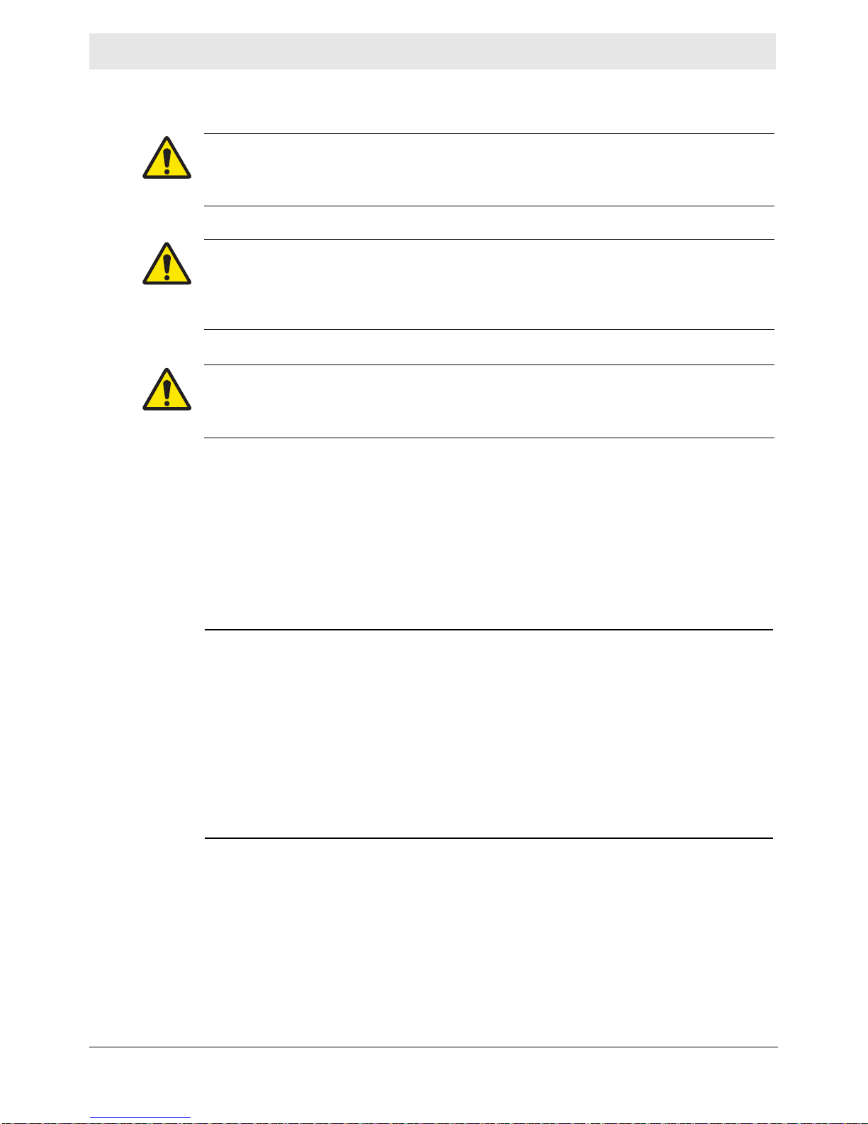
1.1 Signal Words Used in this Manual
This manual contains DANGER, WARNING, CAUTION, NOTICE, and NOTE
signal words which must be followed to reduce the possibility of personal injury,
damage to the equipment, or improper service.
This is the safety alert symbol. It is used to alert you to potential personal hazards.
► Obey all safety messages that follow this symbol.
DANGER
DANGER indicates a hazardous situation which, if not avoided, will result in death
or serious injury.
► To avoid death or serious injury from this type of hazard, obey all safety mes-
sages that follow this signal word.
Safety Information
WARNING
WARNING indicates a hazardous situation which, if not avoided, could result in
death or serious injury.
► To avoid possible death or serious injury from this type of hazard, obey all safety
messages that follow this signal word.
CAUTION
CAUTION indicates a hazardous situation which, if not avoided, could result in
minor or moderate injury.
► To avoid possible minor or moderate injury from this type of hazard,
safety messages that follow this signal word.
NOTICE: Used without the safety alert symbol, NOTICE indicates a situation
which, if not avoided, could result in property damage.
Note: A Note contains additional information important to a procedure.
obey all
wc_tx003567gb_FM10.fm
13
Page 14

Safety Information
1.2 Machine Description and Intended Use
This machine is a mobile electric power source. The Wacker Neuson Mobile
Generator consists of a trailer-mounted cabinet containing an electric alternator, a
fuel tank, and a diesel engine. A control panel, receptacles, and connection lugs
are provided on the side of the cabinet. As the engine runs, the generator converts
mechanical energy into electric power. The operator connects loads to the electric
power receptacles and connection lugs.
This machine is intended for the purpose of supplying electrical power to
connected loads. Refer to the product specifications for the output voltage and
frequency of this generator, and for the maximum output power limit of this
generator.
This machine has been designed and built strictly for the intended use described
above. Using the machine for any other purpose could permanently damage the
machine or seriously injure the operator or other persons in the area. Machine
damage caused by misuse is not covered under warranty.
The following are some examples of misuse:
■ Connecting a load that has voltage and frequency requirements that are
incompatible with the generator output
■ Overloading the generator with a load that draws excessive power during either
continuous running or start-up
■ Operating the generator in a manner that is inconsistent with all federal, state
and local codes and regulations
■ Using the machine as a ladder, support, or work surface
■ Using the machine to carry or transport passengers or equipment
■ Using the machine to tow other machines
■ Operating the machine outside of factory specifications
■ Operating the machine in a manner inconsistent with all warnings found on the
machine and in the Operator’s Manual
Mobile Generator
This machine has been designed and built in accordance with the latest global
safety standards. It has been carefully engineered to eliminate hazards as far as
practicable and to increase operator safety through protective guards and labeling.
However, some risks may rema in even after protective measures have been t aken.
They are called residual risks. On this machine, they may include exposure to:
■ Heat, noise, exhaust, and carbon monoxide from the engine
■ Fire hazards from improper refueling techniques
■ Fuel and its fumes
■ Electric shock and arc flash
■ Personal injury from improper lifting the trailer tongue
■ Typical hazards related to towing a trailer on roads and highways
To protect yourself and others, make sure you thoroughly read and understand the
safety information presented in this manual before operating the machine.
14
wc_tx003567gb_FM10.fm
Page 15

Mobile Generator
1.3 Safety Guidelines for Operating the Machine
Safety Information
Operator
training
Operator
qualifications
Before operating the machine:
■ Read and understand the operating instructions contained in all manuals
delivered with the machine.
■ Familiarize yourself with the location and proper use of all controls and safety
devices.
■ Contact Wacker Neuson for additional training if necessary.
When operating this machine:
■ Do not allow improperly trained people to operate the machine. People
operating the machine must be familiar with the potential risks and hazards
associated with it.
Only trained personnel are permitted to start, operate, and shut down the machine.
They also must meet the following qualifications:
■ have received instruction on how to properly use the machine
■ are familiar with required safety devices
The machine must not be accessed or operated by:
■ children
■ people impaired by alcohol or drugs
Application
area
Safety
devices,
controls, and
attachments
Be aware of the application area.
■ Keep unauthorized personnel, children, and pets away from the machine.
■ Remain aware of changing positions and the movement of other equipment and
personnel in the application area/job site.
■ Identify whether special hazards exist in the application area, such as toxic
gases, or unstable ground conditions, and take appropriate action to eliminate
the special hazards before using the machine.
Be aware of the application area.
■ Do not operate the machine in areas that contain flammable objects, fuels, or
products that produce flammable vapors.
Only operate the machine when:
■ All safety devices and guards are in place and in working order.
■ All controls operate correctly.
■ The machine is set up correctly according to the instructions in the Operator’s
Manual.
■ The machine is clean.
■ The machine’s labels are legible.
To ensure safe operation of the machine:
■ Do not operate the machine if any safety devices or guards are missing or
inoperative.
■ Do not modify or defeat the safety devices.
■ Only use accessories or attachments that are approved by Wacker Neuson.
wc_tx003567gb_FM10.fm
15
Page 16

Safety Information
Mobile Generator
Safe
operating
practices
Personal
Protective
Equipment
(PPE)
After use
When operating this machine:
■ Remain aware of the machine’s moving parts. Keep hands, feet, and loose
clothing away from the machine’s moving parts.
When operating this machine:
■ Do not operate a machine in need of repair.
■ Do not consume the operating fluids used in this machine. Depending on your
machine model, these operating fluids may include water, wetting agents, fuel
(gasoline, diesel, kerosene, propane, or natural gas), o il, coolant, hydraulic fluid,
heat transfer fluid (propylene glycol with additives), battery acid, or grease.
Wear the following Personal Protective Equipment (PPE) while operating this
machine:
■ Close-fitting work clothes that do not hinder movement
■ Safety glasses with side shields
■ Hearing protection
■ Safety-toed footwear
■ Stop the engine when the machine is not being operated.
■ Close the fuel valve on engines equipped with one when the machine is not
being operated.
■ Ensure that the machine will not tip over, roll, slide, or fall when not being
operated.
■ Store the machine properly when it is not being used. The machine should be
stored in a clean, dry location out of the reach of children.
16
wc_tx003567gb_FM10.fm
Page 17

Mobile Generator
1.4 Service Safety
Safety Information
Service
training
Precautions
Before servicing or maintaining the machine:
■ Read and understand the instructions contained in all manuals delivered with
the machine.
■ Familiarize yourself with the location and proper use of all controls and safety
devices.
■ Only trained personnel shall troubleshoot or repair problems occurring with the
machine.
■ Contact Wacker Neuson for additional training if necessary.
When servicing or maintaining this machine:
■ Do not allow improperly trained people to service or maintain the machine.
Personnel servicing or maintaining the machine must be familiar with the
associated potential risks and hazards.
Follow the precautions below when servicing or maintaining the machine.
■ Read and understand the service procedures before performing any service to
the machine.
■ All adjustments and repairs must be completed before operating the machine.
Do not operate the machine with a known problem or deficiency.
■ All repairs and adjustments shall be completed by a qualified technician.
■ Turn off the machine before performing maintenance or making repairs.
■ Remain aware of the machine’s moving parts. Keep hands, feet, and loose
clothing away from the machine’s moving parts.
■ Re-install the safety devices and guards after repair and maintenance
procedures are complete.
Machine
modifications
Replacing
parts and
labels
Cleaning
wc_tx003567gb_FM10.fm
When servicing or maintaining the machine:
■ Use only accessories/attachments that are approved by Wacker Neuson.
When servicing or maintaining the machine:
■ Do not defeat safety devices.
■ Do not modify the machine without the express written approval of Wacker
■ Replace worn or damaged components.
■ Replace all missing and hard-to-read labels.
■ When replacing electrical components, use components that are identical in
■ When replacement parts are required for this machine, use only Wacker
When cleaning and servicing the machine:
■ Keep the machine clean and free of debris such as leaves, paper, cartons, etc.
■ Keep the labels legible.
Neuson.
rating and performance to the original components.
Neuson replacement parts or those p arts equivalent to the original in a ll types of
specifications, such as physical dimensions, type, strength, and material.
17
Page 18

Safety Information
When cleaning the machine:
■ Do not clean the machine while it is running.
■ Never use gasoline or other types of fuels or flammable solvents to clean the
machine. Fumes from fuels and solvents can become explosive.
Mobile Generator
Personal
Protective
Equipment
(PPE)
Electrical
service safety
Cooling
system safety
Wear the following Personal Protective Equipment (PPE) while servicing or
maintaining this machine:
■ Close-fitting work clothes that do not hinder movement
■ Safety glasses with side shields
■ Hearing protection
■ Safety-toed footwear
In addition, before servicing or maintaining the machine:
■ Tie back long hair.
■ Remove all jewelry (including rings).
■ Make sure clothing and shoes are dry , st and on a dry wooden plat form or rubber
insulating mat, and use tools with insulated handles when servicing the
machine.
■ Do not allow water to accumulate around the base of the machine. If water is
present, move the machine and allow the machine to dry before servicing.
■ Do not pressure wash the control panel, generator end, or any other electrical
components when cleaning the machine.
■ Do not attempt to open the radiator cap while the unit is running or before the
engine has cooled down. Severe burns may result!
■ Engine coolant is toxic to humans and animals. Clean up spills and dispose of
waste engine coolant in accordance with local environmental regulations.
18
wc_tx003567gb_FM10.fm
Page 19
Mobile Generator
Safety Information
1.5 Operator Safety while Using Internal Combustion Engines
WARNING
Internal combustion engines present special hazards during operation and fueling.
Failure to follow the warnings and safety standards could result in severe injury or
death.
► Read and follow the warning instructions in the engine owner’s manual and the
safety guidelines below.
DANGER
Exhaust gas from the engine contains carbon monoxide, a deadly poison.
Exposure to carbon monoxide can kill you in minutes.
► NEVER operate the machine inside an enclosed area, such as a tunnel, unless
adequate ventilation is provided through such items as exhaust fans or hoses.
Operating
safety
Refueling
safety
When running the engine:
■ Keep the area around exhaust pipe free of flammable materials.
■ Check the fuel lines and the fuel tank for leaks and cracks before starting the
engine. Do not run the machine if fuel leaks are present or the fuel lines are
loose.
When running the engine:
■ Do not smoke while operating the machine.
■ Do not run the engine near sparks or open flames.
■ Do not touch the engine or muffler while the engine is running or immediately
after it has been turned off.
■ Do not operate a machine when its fuel cap is loose or missing.
■ Do not start the engine if fuel has spilled or a fuel odor is present. Move the
machine away from the spill and wipe the machine dry before starting.
When refueling the engine:
■ Clean up any spilled fuel immediately.
■ Refill the fuel tank in a well-ventilated area.
■ Re-install the fuel tank cap after refueling.
■ Use suitable tools for refueling (for example, a fuel hose or funnel).
When refueling the engine:
■ Do not smoke.
■ Do not refuel a hot or running engine.
■ Do not refuel the engine near sparks or open flames.
wc_tx003567gb_FM10.fm
19
Page 20
Safety Information
1.6 Safety Guidelines for Mobile Generators
DANGER
Carbon monoxide. Using a generator indoors CAN KILL YOU IN MINUTES.
Generator exhaust contains carbon monoxide (CO). This is a poison you cannot
see or smell. If you can smell the generator exhaust, you are breathing CO. But
even if you cannot smell the exhaust, you could be breathing CO.
► NEVER use a generator inside homes, garages, crawlspaces, or other partly
enclosed areas. Deadly levels of carbon monoxide can build up in these areas.
Using a fan or opening windows and doors does NOT supply enough fresh air.
► ONLY use a generator outside and far away from windows, doors, and vents.
These openings can pull in generator exhaust.
► Even when you use a generator correctly , CO may leak into the home. ALWA YS
use a battery-powered or battery-backup CO alarm in the home.
► If you start to feel sick, dizzy, or weak after the generator has been running,
move to fresh air RIGHT AW AY. See a doctor. You could have carbon monoxide
poison.
Mobile Generator
Installing as
backup power
WARNING
Electrocution hazard. Machines that generate electric power present special
hazards while the engine is running. These include the risk of electrocution or
severe electrical shock.
► Read and follow the instructions in this Operator’s Manual.
Special hazards exist when installing this machine as a backup power supply.
Improper connection of generator to a building’s electrical system can allow
electrical current from the generator to backfeed into utility lines. This may result in
electrocution of utility workers, fire, or explosion.
WARNING
Backfeed from the generator into the public power distribution system can cause
serious injury or death to utility workers!
► Connections to a building’s electrical system must be made by a qualified elec-
trician and comply with all applicable laws and electrical codes.
If connected to a building’s electrical system, the generator must meet the power,
voltage, and frequency requirements of the equipment in the building. Differences
in power, voltage, and frequency requirements may exist and improper connectio n
may lead to equipment damage, fire, and personal injury or death.
20
wc_tx003567gb_FM10.fm
Page 21

Mobile Generator
Safety Information
General safety
Ground
connection
■ Do not use evaporative starting fluids to start the engine. They are highly
explosive.
■ Do not store items such as excess oil, rags, or tools on top of or inside the
machine. These items are a fire hazard and can restrict cooling air.
■ Ensure that electrical cords attached to the machine are in serviceable condition
without cuts, cracks, or exposed wires.
■ Do not route electrical cords over vibrating or hot parts of the machine.
■ Do not stand on the machine.
■ Do not enclose or cover the machine when it is use, or when it is hot.
The generator must be connected to a good earthen ground for proper operating
safety.
A central “equipment ground” is provided at the customer connection lugs. This
point is connected directly to the generator set base. All other system grounds are
connected to this central point. Ground the generator in accordance with the
standards defined in national, state, and local regulations.
wc_tx003567gb_FM10.fm
21
Page 22

Safety Information
1.7 Safety Guidelines for Towing the Machine
WARNING
Risk of severe injury or death. Improper trailer condition and towing technique can
lead to an accident.
► Obey the trailer manufacturer’s instructions and the instructions below to reduce
the risk of an accident.
When towing the machine:
■ Do not tow the machine if the towing vehicle’s hitch or the trailer’s coupler are
damaged.
■ Do not tow the machine if any of the trailer’s lug nuts are missing.
■ Do not tow the machine if the trailer’s tires have less than 1.5 mm (1/16 inch) of
tread.
■ Do not tow the machine unless the trailer’s brakes are functioning properly.
■ Do not exceed the trailer manufacturer’s speed limitations.
When towing the machine:
■ Only tow the machine when the trailer’s lug nuts are properly torqued.
■ Only tow the machine when the trailer’s tires are properly inflated.
■ Only tow the machine when all trailer lights are functioning correctly.
■ Only tow the machine when the trailer’s safety chains are connected to the
towing vehicle in a crisscross pattern.
■ Maintain extra distance between the towing vehicle and other vehicles.
■ Avoid soft shoulders, curbs, and sudden lane changes.
■ Abide by all licensing requirements for your area.
Mobile Generator
If you have not driven a towing vehicle with trailer before, practice turning,
stopping, and backing up the towing vehicle with trailer in an area away from traffic.
Only drive the towing vehicle with trailer when you are confident in your ability to do
so.
wc_tx003567gb_FM10.fm
22
Page 23

Mobile Generator
1.8 Safety Guidelines for Lifting the Machine
When lifting the machine:
■ Make sure slings, chains, hooks, ramps, jacks, forklifts, cranes, hoists, and any
other type of lifting device used is attached securely and has enough weightbearing capacity to lift or hold the machine safely. See section Technical Data
for machine weight.
■ Remain aware of the location of other people when lifting the machine.
■ Only use the lifting points and tie downs described in the Operator’s Manual.
■ Make sure the transporting vehicle has sufficient load cap acity and platform size
to safely transport the machine.
To reduce the possibility of injury:
■ Do not stand under the machine while it is being lifted or moved.
■ Do not get onto the machine while it is being lifted or moved.
1.9 Reporting Safety Defects
Safety Information
If you believe your trailer has a defect which could cause a crash or could cause
injury or death, you should immediately inform the National Highway Traffic Safety
Administration (NHTSA) in addition to notifying Wacker Neuson.
If NHTSA receives similar complaints, it may open an investigation; and if it finds
that a safety defect exists in a group of trailers, it may order a recall and remedy
campaign. However, NHTSA cannot become involved in individual problems
between you, your dealer, or Wacker Neuson.
To contact NHTSA, you may either contact the Vehicle Safety Hotline toll-free at
1-888-327-4236 (TTY: 1-800-424-9153); go to http://www.safercar.gov; or write to:
Administrator
NHTSA
1200 New Jersey Avenue S.E.
Washington, DC 20590
You can also obtain other information about your motor vehicle safety from
http://www.safercar.gov
wc_tx003567gb_FM10.fm
23
Page 24
Label Locations G 25
GG
GG
JJ
C
H
F
VV
EE
K
E
W
D
X
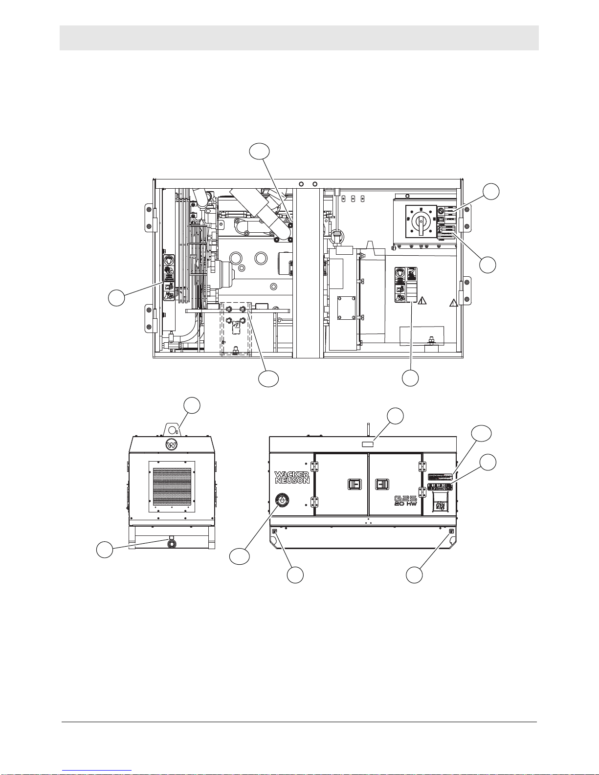
wc_gr011688
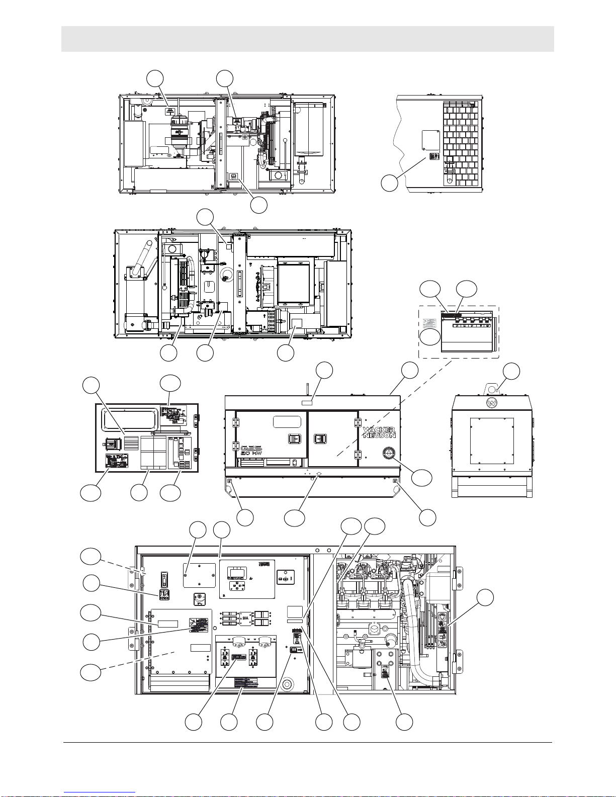
2 Label Locations
24
wc_si000835gb_FM10.fm
Page 25
wc_gr011684
A
Ø
HZ
V
R
Basler
DIAGNOSTICS
DIAGNOSEN
DIAGNOSTICOS
DIAGNOSTICS
AUSAUS
APAGADOAPAGADO
ARRETARRET
OFFOFF
REMOTE STARTREMOTE START
FERNSTARTFERNSTART
ARRANQUE REMOTOARRANQUE REMOTO
DEMARRAGE A DEMARRAGE A
DISTANCEDISTANCE
START / LAUFENSTART / LAUFEN
ARRANQUE / MARCHAARRANQUE / MARCHA
DEMARRER / MARCHEDEMARRER / MARCHE
START / RUNSTART / RUN
T4i
T4f
J J
B
D
I
G
C
P
M
M
JT J
SS TT
RR
DD
JJ
AAMM
FF
G
NO
KK
L
CC
Y
Z S V R N
Q1
BB
QQ
Q2
I
X
G 25 Label Locations
wc_si000835gb_FM10.fm
25
Page 26
Label Meanings G 25
INSTRUCCIONES DE REMOLQUEINSTRUCCIONES DE REMOLQUE
1.LEA EL MANUAL DEL OPERARIO.1.LEA EL MANUAL DEL OPERARIO.
2.UTILICE UN ACOPLE CORRECTAMENTE 2.UTILICE UN ACOPLE CORRECTAMENTE
CLASIFICADO PARA LA "CLASE DE PESO CLASIFICADO PARA LA "CLASE DE PESO
BRUTO" DEL VEHICULO DEL REMOLQUE. BRUTO" DEL VEHICULO DEL REMOLQUE.
3.ASEGURESE DE AMARRAR CORRECTAMENTE EL 3.ASEGURESE DE AMARRAR CORRECTAMENTE EL
REMOLQUE AL VEHICULO DE REMOLQUE. REMOLQUE AL VEHICULO DE REMOLQUE.
4.FIJE EN CRUZ LAS CADENAS DE SEGURIDAD.4.FIJE EN CRUZ LAS CADENAS DE SEGURIDAD.
5.FIJE EN EL VEHICULO DE REMOLQUE 5.FIJE EN EL VEHICULO DE REMOLQUE
LA CADENA DE DESPRENDIMIENTO. LA CADENA DE DESPRENDIMIENTO.
6.CONTROLE LAS LUCES DEL REMOLQUE.6.CONTROLE LAS LUCES DEL REMOLQUE.
1.READ OPERATOR'S MANUAL. 1.READ OPERATOR'S MANUAL.
2.USE HITCH RATED FOR TRAILER'S 2.USE HITCH RATED FOR TRAILER'S
"GROSS VEHICLE WEIGHT RATING". "GROSS VEHICLE WEIGHT RATING".
3.SECURELY ATTACH TRAILER TO TOW VEHICLE.3.SECURELY ATTACH TRAILER TO TOW VEHICLE.
4.ATTACH SAFETY CHAINS USING CROSS 4.ATTACH SAFETY CHAINS USING CROSS
PATTERN. PATTERN.
5.ATTACH BREAKDOWN CHAIN TO VEHICLE.5.ATTACH BREAKDOWN CHAIN TO VEHICLE.
6.CHECK TRAILER LIGHTS.6.CHECK TRAILER LIGHTS.
TOWING INSTRUCTIONSTOWING INSTRUCTIONS ABSCHLEPPINSTRUKTIONENABSCHLEPPINSTRUKTIONEN
1.BETRIEBSVORSCHRIFT LESEN.1.BETRIEBSVORSCHRIFT LESEN.
2.ANHANGEVORRICHTUNG VERWENDEN, 2.ANHANGEVORRICHTUNG VERWENDEN,
DIE DER GESAMTBETRIEBSGEWICHTSKLASSE DIE DER GESAMTBETRIEBSGEWICHTSKLASSE
ENTSPRICHT. ENTSPRICHT.
3.ANHANGER SICHER AM ZUGFAHRZEUG 3.ANHANGER SICHER AM ZUGFAHRZEUG
BEFESTIGEN. BEFESTIGEN.
4.SICHERHEITSKETTEN KREUZWEISE ANBRINGEN.4.SICHERHEITSKETTEN KREUZWEISE ANBRINGEN.
5.ABREISSKETTE AM FAHRZEUG ANBRINGEN.5.ABREISSKETTE AM FAHRZEUG ANBRINGEN.
6.ANHANGERLEUCHTEN PRUFEN.6.ANHANGERLEUCHTEN PRUFEN.
....
....
....
....
INSTRUCTIONS DE REMORQUAGEINSTRUCTIONS DE REMORQUAGE
1.LIRE LA NOTICE D'EMPLOI.1.LIRE LA NOTICE D'EMPLOI.
2.UTILISER UN CROCHET D'ATTELAGE CONFORME2.UTILISER UN CROCHET D'ATTELAGE CONFORME
AU DEBIT NOMINAL DU POIDS BRUT DE AU DEBIT NOMINAL DU POIDS BRUT DE
VEHICULE DU VEHICULE TRACTEUR. VEHICULE DU VEHICULE TRACTEUR.
3.ATTACHER LA REMORQUE FERMEMENT AU 3.ATTACHER LA REMORQUE FERMEMENT AU
VEHICULE TRACTEUR. VEHICULE TRACTEUR.
4.ATTACHER LES CHAINES DE SURETE EN 4.ATTACHER LES CHAINES DE SURETE EN
UTILISANT UNE METHODE CROISEE. UTILISANT UNE METHODE CROISEE.
5.ATTACHER LA CHAINE DE REMORQUAGE AU VEHICULE.5.ATTACHER LA CHAINE DE REMORQUAGE AU VEHICULE.
6.VERIFIER LES LAMPES DE LA REMORQUE.6.VERIFIER LES LAMPES DE LA REMORQUE.
117960117960
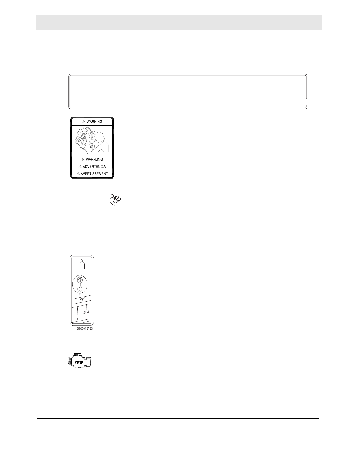
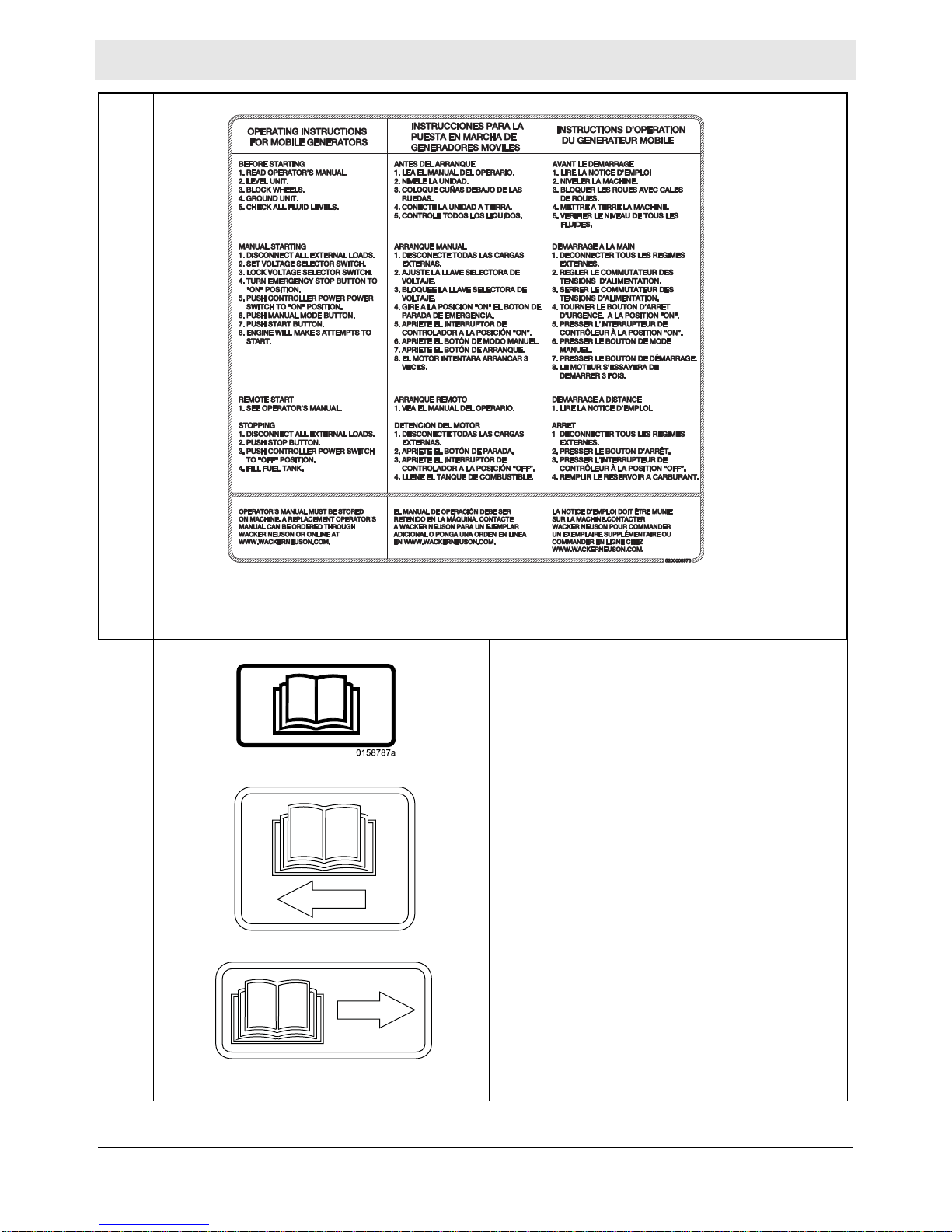
3 Label Meanings
A
(on trailer , if equipped)
B WARNING
Pressurized contents. Do not open when hot!
C WARNING
Lock doors. Access can cause electric shock or
injury.
D NOTICE
Lifting point
E NOTICE
Never change switch position with engine
running. Results in damage to machine.
26
wc_tx003634gb_FM10.fm
Page 27
G 25 Label Meanings
113726
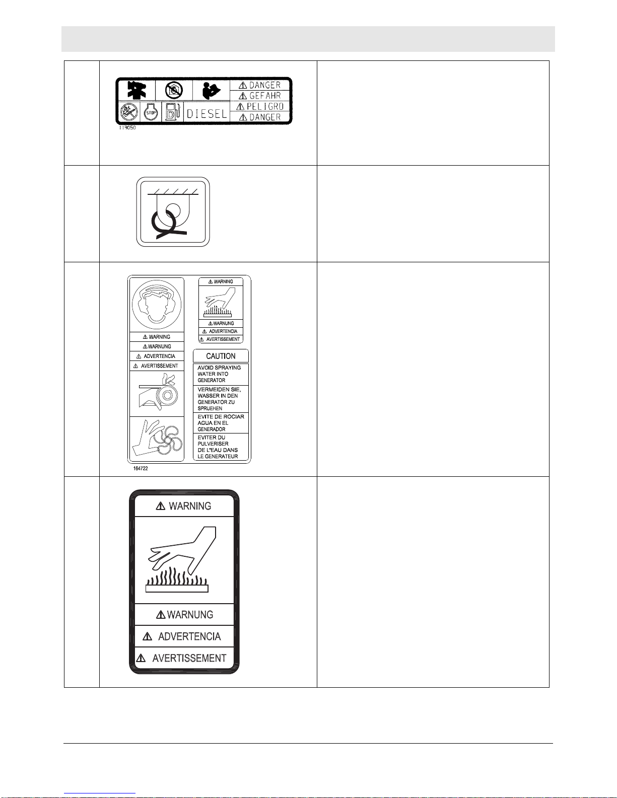
F DANGER
Asphyxiation hazard. Do not run the machine
indoors or in an enclosed area without adequate
ventilation. Read the Operator’s Manual for
instructions. No sparks, flames, or burning
objects near machine. Stop the engine before
adding fuel. Use only diesel fuel.
G Tie-down point
113726
H WARNING
To prevent hearing loss, wear hearing protection.
Hand injury if entangled in moving belt.
Rotating machinery! Do not reach inside with
engine running.
WARNING
Hot surface
CAUTION
Avoid spraying water into generator.
I WARNING
Hot surface
wc_tx003634gb_FM10.fm
27
Page 28
Label Meanings G 25
J Electrical ground
K WARNING
Electric shock and arc flash can cause serious
injury or death.
L
28
wc_tx003634gb_FM10.fm
Page 29
G 25 Label Meanings
L
M Operator’s Manual must be stored on machine.
Replacement Operator’s Manual can be ordered
through your local Wacker Neuson distr ibutor.
wc_sy0158787
wc_sy0160602
wc_tx003634gb_FM10.fm
29
Page 30
Label Meanings G 25
AND
N WARNING!
Operation of this equipment may create sparks
Operation of This Equipment May Create Sparks That Can Start Fires Around Dry
Vegetation. A Spark Arrestor May be Required. The Operator Should Contact Local
Fire Agencies For Laws or Regulations Relating to Fire Prevention Requirements.
WARNING
Per CAL. PRC. CODE
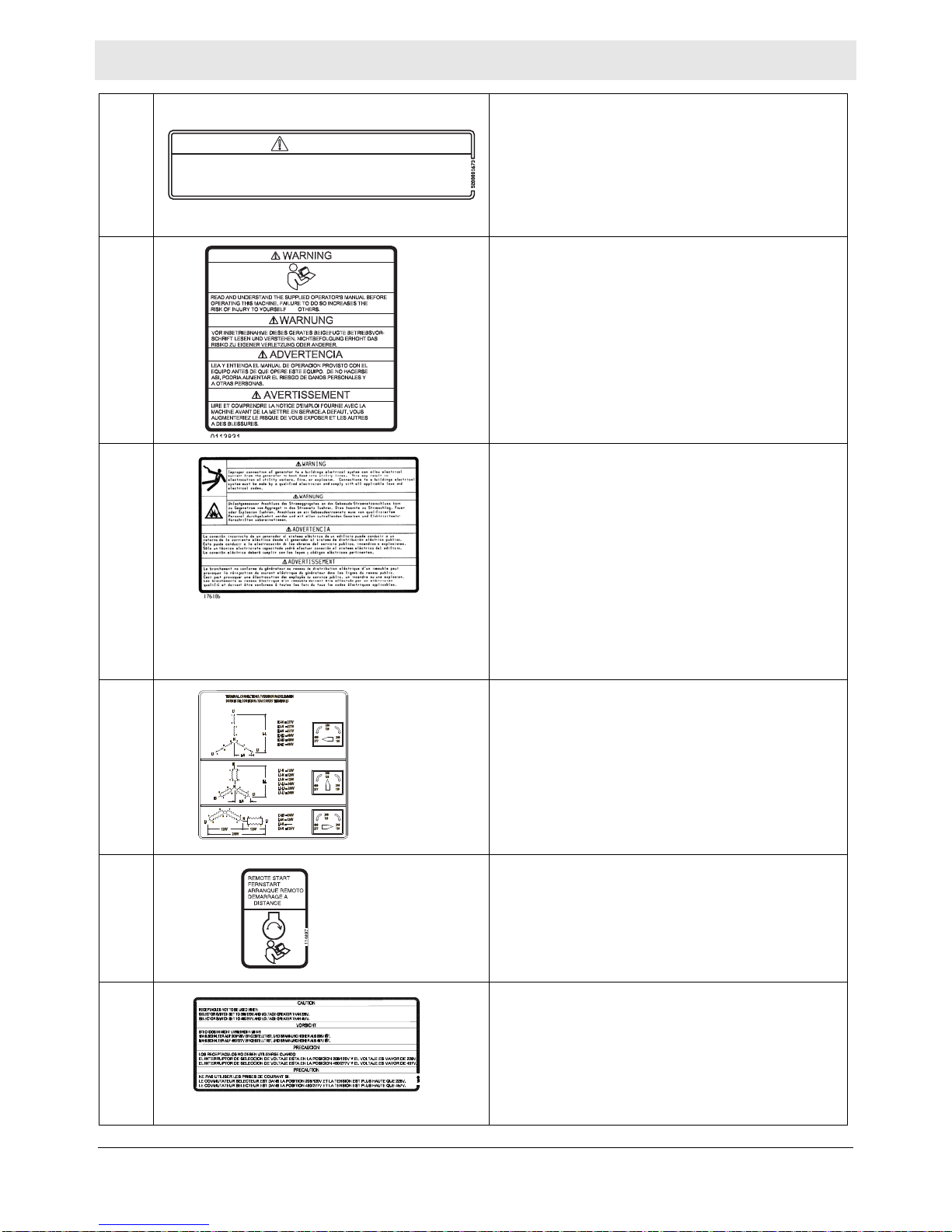
P Read and understand the supplied Operator’s
Q1 WARNING
that can start fires around dry vegetation. A sp ark
arrestor may be required. The operator should
contact local fire agencies for laws or regulations
relating to fire prevention requirements.
Manual before operating the machine. Failure to
do so increases the risk of injury to yourself and
others.
To reduce the risk of electrical shock and arc
flash, read the Operator’s Manual. Improper
connection of the generator to a building’s
electrical system can allow electrical current from
the generator to backfeed into utility lines. This
may result in electrocution of utility workers, fire,
or explosion. Connections to a building’s
electrical system must be made by a qualified
electrician and comply with all applicable laws
and electrical codes.
Q2 Voltage selector label
R Remote start operation. Read Operator’s Manual
for instructions.
S CAUTION
Receptacles not to be used when:
Selector switch set to 208/120V and voltage
greater than 228V.
Selector switch set to 480/277V and voltage
greater than 457V.
30
wc_tx003634gb_FM10.fm
Page 31

G 25 Label Meanings
T WARNING
Disconnect battery before servicing.
Read the Operator’s Manual.
U
(on trailer, if equipped)
W Drain containment system.
X WARNING
To prevent hearing loss, wear hearing protection
when operating the machine.
WARNING
Pressurized contents. Do not open when hot!
WARNING
Hand injury if entangled in moving belt.
WARNING
Rotating machinery! Do not reach inside
machine with engine running.
wc_tx003634gb_FM10.fm
31
Page 32

Label Meanings G 25
Y Operating the main circuit breaker supplies or
interrupts power to the customer connection lugs.
Z Neutral bonded to frame
AA Fuses
Read the Operator’s Manual for machine
information.
BB WARNING
CC Generator and receptacle wiring
Electric shock at cooling fins.
wc_tx003634gb_FM10.fm
32
Page 33

G 25 Label Meanings
DD Engine wiring
EE WARNING
Hot surface
FF (if equipped)
Battery disconnect must be in “ON” position to
start engine.
NOTICE
Do not use the battery disconnect switch while
engine is running. Damage to the electrical
components may occur.
GG Low sulfur fuel or ultra low sulfur fuel only.
JJ Protecting Our Environment
Fluid containment system
wc_tx003634gb_FM10.fm
33
Page 34

Label Meanings G 25
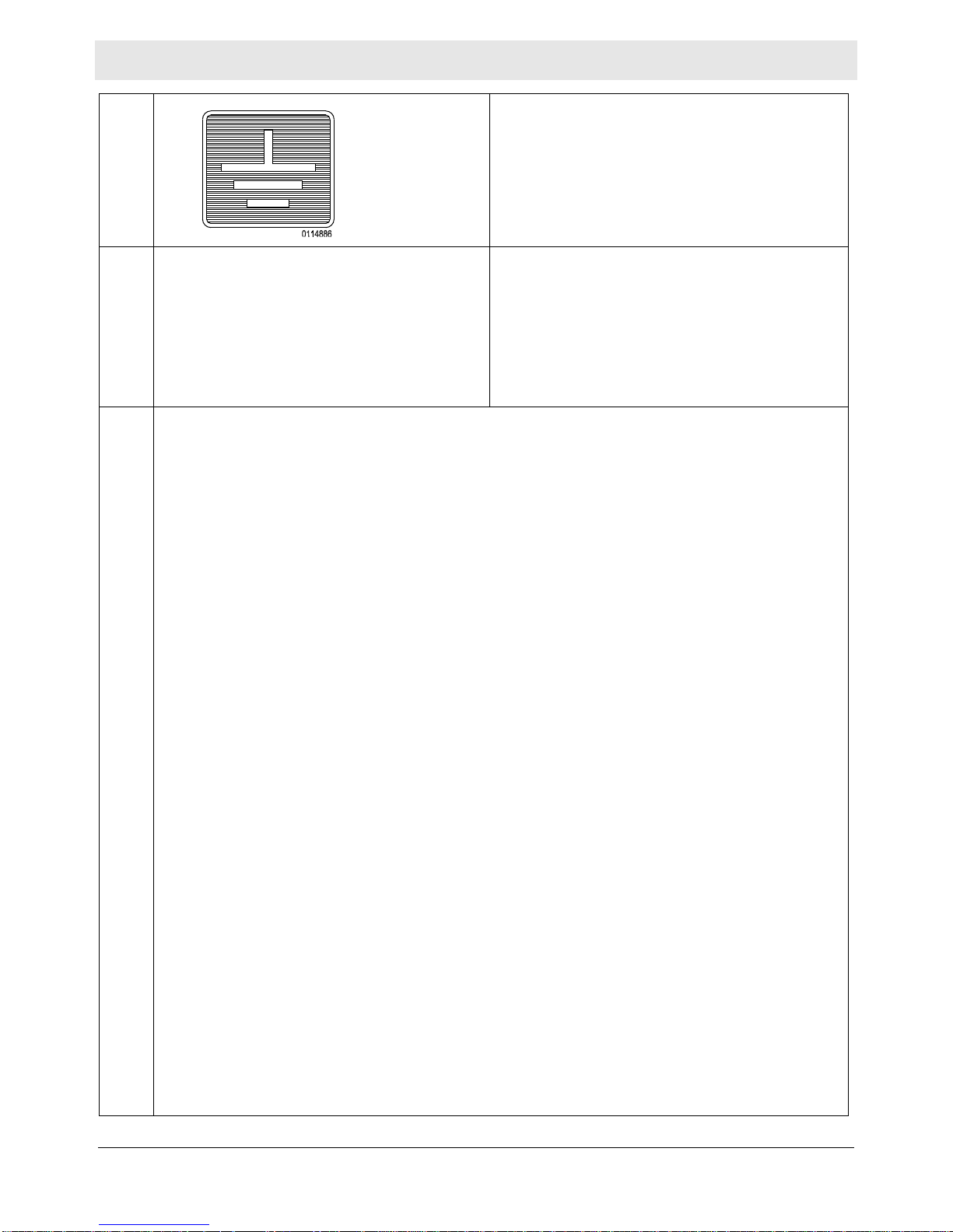
KK Diagnostic menu navigation
MM This machine may be covered by one or more
patents.
NN
QQ (Camlock models only)
RR (Camlock models only)
(on trailer , if equipped)
(On trailer, if equipped)
Certification Label (VIN Number)
Also attached to each unit is a Certification Label.
This label specifies that the trailer conforms with
all Federal Motor Vehicle Standards in effect at
the time of manufacture. The label includes the
Vehicle Identification Number (VIN) for the trailer.
Lug door must be closed for lugs and recept acles
to energize.
WARNING
Electric shock can cause serious injury or death.
34
wc_tx003634gb_FM10.fm
Page 35

G 25 Label Meanings
0183199
SS (Camlock models only)
NOTICE
Separate overcurrent protection must be
provided. Do not exceed 400 amps per
receptacle.
TT (Camlock models only)
WARNING
Electric shock and arc flash can cause serious
injury or death.
UU WARNING
Explosion hazard. Do not use evaporative
starting fluids such as ether on this engine. The
engine is equipped with a cold starting aid. Using
evaporative starting fluids can cause an
explosion which can cause engine damage,
personal injury, or death. Read and follow the
engine starting instructions in this Operator's
Manual.
V V WARNING
Keep all sparks and open flames away from
the battery.
Wear eye protection.
Keep away from children.
0183199
Battery acid is poisonous and corrosive.
Read the Operator’s Manual.
Explosion hazard.
Dispose of waste batteries in accordance with
local environmental regulations. Battery contains
mercury (Hg), cadmium (Cd), or lead (Pb).
WW WARNING
Operation of this equipment may create sparks
that can start fires around dry vegetation. A spark
arrester may be required. The operator should
contact local fire agencies for laws or regulations
relating to fire prevention requirements.
wc_tx003634gb_FM10.fm
35
Page 36

Lifting and Transporting
4 Lifting and Transporting
4.1 Lifting the Machine
Mobile Generator
Requirements
Lifting the
machine
■ Lifting equipment (crane, hoist, or fork truck) capable of supporting the
machine’s weight
■ Lifting devices (hooks, chains, and shackles) capable of supporting the
machine’s weight
■ Engine stopped
A lifting eye is used for lifting the machine.
wc_gr011429
Perform the procedure below to lift the machine.
1. Attach the lifting devices and equipment to the lifting eye. Do not attach lifting
devices to any other part of the machine.
2. Lift the machine a small distance.
WARNING
Crushing hazard. An unstable machine may cause the lifting devices and
equipment to fail. You may be crushed if the lifting devices and equipment fail.
► Check for stability before continuing.
3. Check for stability . If necessary, lower the machine, reposition the lifting devices,
and lift the machine a small distance again.
4. Continue lifting the machine only when it is stable.
36
wc_tx003570gb_FM10.fm
Page 37

Mobile Generator
4.2 Before Towing Checklist
Before towing the machine, check the licensing requirements for trailers in your
area. Also check the following items:
Towing vehicle
Check that the towing vehicle is rated to tow the load.
Check that the towing vehicle is in serviceable condition.
Do any necessary service/maintenance on the towing vehicle.
Hitch and coupler
Check that the towing vehicle and hitch have a rating equal to or greater than
the GVWR of the machine. See Technical Data.
Check that the hitch of the towing vehicle and coupler of the trailer are compatible.
Check the condition of both the coupler and the hitch.
Check that all fasteners on the coupler are tight.
Check that the coupler has fresh grease applied to it.
Wheels
Check that wheel chocks are available at the work site.
Check that all lug nuts are in place and are properly torqued.
Check the tread wear of the tires.
Check that the tires are inflated to the proper pressure.
Lifting and Transporting
Trailer preparation
Check that all doors and access panels are closed and latched.
Check that outriggers (if applicable) are retracted.
Check local regulations regarding hazardous materials placards. If applicable,
install the appropriate placards.
Trailer operation
Check that the trailer jacks are in the traveling (horizontal) position.
Check that the directional and running lights on the trailer function correctly.
Check that the safety chains of the trailer are connected to the towing vehicle
using a crisscross pattern.
Check the operation of the trailer brakes by brakin g the towing vehicle at a slow
speed. Both the vehicle and the trailer must brake smoothly. If the trailer pushes,
check the fluid level in the surge brakes or the operation of the electric brakes.
Check tha t the trailer’s breakaway cable (if applicable) is attached to the towin g
vehicle.
Test the function of the breakaway system (if applicable).
wc_tx003570gb_FM10.fm
37
Page 38

Lifting and Transporting
wc_gr011430
b
a
c
4.3 Towing the Machine
Mobile Generator
Background
Brakes
Licensing
requirements
The generator’s trailer is equipped with brakes (surge or electric), safety chains (a),
lights, and a coupler (pintle or ball-type) (b).
Only use the brakes as designed.
■ The breakaway cable (c) is not a parking brake and should not be used as one.
■ In most states, large trailers must be registered and licensed by the State
Department of Transportation. Before towing, be sure to check licensing
requirements.
■ Drivers towing trailers may be required to carry a commercial driver’s license
(CDL). Check your local and state licensing regulations before towing the
generator.
Coupler
maintenance
Towing safety
■ A film of grease on the coupler will extend coupler life and eliminate squeaking.
Wipe the coupler clean and apply fresh grease each time the trailer is towed.
■ When towing, maintain extra space between vehicles and avoid soft shoulders,
curbs and sudden lane changes. If you have not pulled a trailer before, practice
turning, stopping, and backing up in an area away from heavy traffic.
■ Do not exceed 55 mph when towing a trailer.
38
wc_tx003570gb_FM10.fm
Page 39

Mobile Generator
Lifting and Transporting
4.4 Preparing the Machine for Transport on a Truck or Trailer
Requirements
Checklist
■ Machine stopped
■ Flatbed truck or trailer capable of supporting the machine’s weight
■ Chains, hooks, or straps capable of supporting the machine’s weight
WARNING
Crushing hazard. Improperly securing the machine can lead to a crushing hazard.
► Use only the designated tie-down points to secure the machine to a truck or
trailer.
Before transporting the machine, check the following items:
Machine
Check that all accessories are securely stored within the machine.
Check that all doors and access panels of the machine are closed.
Check that all electrical supplies are disconnected from the machine.
For machines with external fuel supplies, check that all fuel supplies are
disconnected from the machine.
For machines with generators, check that the generator is shut down.
Loading and transporting equipment
Check t hat the transport vehicle or trailer can sup port the weight of the machine.
Check that the transport vehicle or trailer is wide enough to support the
machine.
Check that the wheels of the transport vehicle or trailer are chocked during the
loading process.
Check that the transport vehicle or trailer is clean and free of grease, oil, ice,
and other loose material.
If the machine is mounted to a trailer, check that the jackstand or other transport
block (piece of wood or other similar material) is available to support the trailer
tongue during transporting. Do not use the machine’s trailer jack to support the
trailer tongue during transporting.
Check that any ramps used in the loading process:
■ Can support the weight of the machine.
■ Are clean and free of grease, oil, ice, and other loose material.
■ Are securely connected to the transport vehicle or trailer.
■ Are of sufficient length to keep the loading angle 15° or less.
In addition:
Check that the loading area is flat and the ground is stable.
Check the overall height of the machine once it is loaded on the truck or trailer.
Plan your travel route so there will be adequate clearance for overpasses, road
signs, buildings, etc.
Check local regulations regarding transporting and obey these regulations.
wc_tx003570gb_FM10.fm
39
Page 40

Lifting and Transporting
4.5 Hazardous Materials Placards
Mobile Generator
Overview
Requirements
Hazardous materials placards may have been provided with your machine.
Transport Canada, and the Canadian Transportation of Dangerous Goods Act,
require that these hazardous materials placards be permanently applied to certain
machines if they are to be transported or towed on Canadian roads.
Contact Transport Canada if you have questions about driver’s licensing
requirements for transporting machines that bear hazardous materials placard, or
questions about other restrictions for use of this machine
Note: The owner/operator of this machine is responsible for applying the placards.
Use the procedure described below.
wc_gr009231
■ Placard mounting surfaces and surrounding ambient temperature should be
at least 10°C (50°F). In colder conditions, see application step 2 below.
■ Mild soap or detergent
■ Fresh, clean, warm water supply
■ Isopropyl (rubbing) alcohol, lacquer thinner, or mineral spirits
■ Soft, clean, dry cloths
■ Plastic squeegee or stiff cardboard
Apply the
Placards
Four placards have been provided with this machine—one for each side, one for
the front, and one for the back.
To apply the placards, do the following.
1. Clean the placard mounting surfaces with mild soap and water. Dry thoroughly.
2. Use isopropyl (rubbing) alcohol to clean the placard mounting surfaces if:
■ they, and the surrounding ambient temperature, are below 10°C (50°F)
■ the placard mounting surfaces are covered with grease and oil.
3. Peel about 2 cm (1 in.) of backing paper from the top of the placard. Fold the
backing paper away from the placard.
4. Apply the top of the placard to the mounting surface. Gradually remove the
backing paper and apply the remainder of the placard. Firmly press and smooth
the placard into place with a plastic squeegee, stiff cardboard, or a soft cloth.
Puncture any air bubbles that may form.
40
wc_tx003570gb_FM10.fm
Page 41

Mobile Generator
wc_gr008509
a
Lifting and Transporting
4.6 Testing the Breakaway System (Hydraulic Surge Brakes)
Requirements
When
Procedure
■ Hydraulic reservoir filled
■ Machine parked on a flat surface
Test the breakaway system:
■ Before towing
■ After filling the hydraulic reservoir
Perform the following procedure to test the breakaway system.
1. Position the machine/trailer on a flat surface.
2. Connect the breakaway cable (a) to the tow vehicle. Do not connect the
machine/trailer to the tow vehicle via the hitch.
b
wc_gr008508
3. Slowly move the tow vehicle so that it pulls on the breakaway cord until the
emergency lever reaches its second notch (b) and locks into the ON position.
4. Connect the machine/trailer to the tow vehicle via the hitch.
5. Attempt to tow the machine/trailer at a very slow speed (less than 5 mph). When
activated, a properly working breakaway system will cause substantial drag on
the trailer wheels and may even cause the trailer wheels to lock.
WARNING
Personal injury hazard. A faulty breakaway system may lead to an accident and
personal injury if the machine/trailer breaks away.
► Do not tow the machine/trailer if the breakaway system is faulty.
6. If the brakes did not function, repair any faults before towing.
This procedure continues on the next page.
wc_tx003570gb_FM10.fm
41
Page 42

Lifting and Transporting
wc_gr008510
c
Continued from the previous page.
7. Stop the tow vehicle.
8. Release the brake by simultaneously pulling on the breakaway cord and prying
the locking spring with a screwdriver (c) or pry bar.
Mobile Generator
Result
The procedure to test the breakaway system is now complete.
42
wc_tx003570gb_FM10.fm
Page 43

Mobile Generator
wc_gr008513
a
Lifting and Transporting
4.7 Testing the Breakaway System (Electric Brakes)
Requirements
When
Procedure
■ Voltmeter
■ Battery charger or backup battery (charged)
Test the breakaway system:
■ Before towing
■ Monthly if the machine is not in service
Perform the following procedure to test the breakaway system.
NOTICE: Disconnect the trailer wiring plug from the tow vehicle before testing.
Failure to do so will result in severe damage to the electronic brake control.
1. Connect the machine/trailer to the tow vehicle.
2. Disconnect the trailer wiring plug (a) from the tow vehicle.
c
b
wc_gr008514
3. Pull the breakaway pin (b) out of the brake switch (c) (to activate the brakes)
and attempt to tow the machine/trailer at a very slow speed (less than 5 mph).
When activated, a properly working breakaway system will cause substantial
drag on the trailer wheels and may even cause the trailer wheels to lock.
4. Stop the tow vehicle.
WARNING
Personal injury hazard. A faulty breakaway system may lead to an accident and
personal injury if the machine/trailer breaks away.
► Do not tow the machine/trailer if the breakaway system is faulty.
This procedure continues on the next page.
wc_tx003570gb_FM10.fm
43
Page 44

Lifting and Transporting
wc_gr008515
d
VDC
1000
200
20
2
200m
F
V
A
V- COM
Continued from the previous page.
5. If the brakes did not function, check the voltage of the breakaway battery.
To do so:
a.Remove the cover of the battery box.
b.Remove the wires connected to the breakaway battery (d).
c.Measure the voltage. If 12–14 VDC is not measured, replace or recharge the
breakaway battery.
Mobile Generator
Result
6. If 12–14 VDC was measured but the brakes did not function, there is a wiring or
mechanical fault with the brakes. Repair any faults before towing.
7. If the brakes function properly:
a.Reconnect the wires to the breakaway battery.
b.Re-install the cover to the battery box.
c.Re-install the breakaway pin (b) into the brake switch.
d.Connect the trailer wiring plug to the tow vehicle.
The procedure to test the breakaway system is now complete.
44
wc_tx003570gb_FM10.fm
Page 45

Mobile Generator
5Machine Setup
5.1 Preparing the Machine for First Use
1. Make sure all loose packaging materials have been removed from the machine.
2. Check the machine and its components for damage. If there is visible damage,
do not operate the machine! Contact your Wacker Neuson dealer immediately
for assistance.
3. Take inventory of all items included with the machine and verify that all loose
components and fasteners are accounted for.
4. Attach component parts not already attached.
5. Add fluids as needed and applicable, including fuel, engine oil, and battery acid.
6. Move the machine to its operating location.
Machine Setup
Safety
information
CO Alarms
■ Do not exceed the power output of the generator . Damage to tools or generator
will occur. Refer to Technical Data.
■ When using the generator as a standby or substitute power supply, make sure
the voltage and phase rotation of the line connections match those of the utility
lines. Failure to match phase rotation and voltage may cause equipment
connected to the generator to operate incorrectly! This could create unsafe
operating conditions.
■ Do not exceed the rated current limit of any receptacle.
■ The bonding bar between the ground connections must remain in place at all
times unless a qualified electrician determines otherwise.
Because this machine produces carbon monoxide (CO), Wacker Neuson
recommends that CO alarms be installed in all structures in close proximity to the
machine. CO alarms provide an extra measure of protection against this poison
that you cannot see or smell.
Install battery-operated CO alarms or plug-in CO alarms with battery backup,
according to the manufacturer’s instructions. CO alarms should be certified to the
requirements of the latest safety standards (UL 2034, IAS 6-96, or CSA 6.19.01).
Test the CO alarm batteries monthly.
wc_tx003572gb_FM10.fm
45
Page 46
Machine Setup
5.2 Positioning the Machine
WARNING
Fire hazard. Do not move the machine while it is running.
► Shut down the machine before moving or repositioning it.
WARNING
Fire hazard. Machines positioned on a hill or an incline may slide, break away or
roll over.
► Do not position the machine on a hill or an incline.
WARNING
Explosion and fire hazard. Risk of severe injury or death.
► Do not operate the machine near flammable vapors, fuels, or combustibles.
Mobile Generator
CO Alarms
Requirements
Because this machine produces carbon monoxide (CO), Wacker Neuson
recommends that CO alarms be installed in all structures in close proximity to the
machine. CO alarms provide an extra measure of protection against this poison
that you cannot see or smell.
Install battery-operated CO alarms or plug-in CO alarms with battery backup,
according to the manufacturer’s instructions. CO alarms should be certified to the
requirements of the latest safety standards (UL 2034, IAS 6-96, or CSA 6.19.01).
Test the CO alarm batteries monthly.
Position the machine:
■ so that engine exhaust will not enter nearby structures.
■ so that the machine does not block traffic.
■ so that the machine is not close to any combustible material or flammable vapor .
■ so that all of the machine’s access doors/panels may be accessed.
■ so that the area overhead is clear of debris that could fall onto or into the
machine or exhaust compartment.
■ so that the machine is on a firm, level surface and will not tip, roll, slide, or fall
while operating.
This procedure continues on the next page.
46
wc_tx003572gb_FM10.fm
Page 47

Mobile Generator
Continued from the previous page.
Machine Setup
Procedure
Result
Perform the following procedure to position the machine.
1. Place the machine on solid, stable, and level ground.
a
wc_gr009186
2. For machines with trailers, install chocks (a) under the wheels.
The machine is now properly positioned.
wc_tx003572gb_FM10.fm
47
Page 48

Machine Setup
wc_gr011524
5.3 Grounding the Generator
Mobile Generator
Location
Function
A ground connection is located at the customer connection terminal lugs.
This ground connection is used for electrically grounding the generator when
necessary to comply with the National Electrical Code and other federal, state, and
local regulations. For grounding requirements in your area, consult with a qualified
electrician, electrical inspector, or local agency having jurisdiction over electrical
compliance.
■ If the generator is used at a construction site, there may be additional
regulations which must be observed.
■ In some areas, generators are required to be registered with local utility
companies.
48
wc_tx003572gb_FM10.fm
Page 49

Mobile Generator
5.4 Recommended Fuel
Low temperatures cause diesel fuel to gel. Always use the proper fuel for the
conditions. Follow the guidelines in the table below.
Machine Setup
Lowest expected ambient
temperature
Above freezing
< 0°C (32°F)
Below freezing
> 0°C (32°F)
1
Your engine may require ultra low sulfur fuel. Consult the engine owner’s manual.
Recommended fuel
#2 diesel plus additives
Winter-blend diesel
1
NOTICE: Consult the engine owner’s manual regarding the use of biodiesel fuel in
this machine. Some biodiesel blends may clog the fuel system or gel at cold
ambient temperatures sooner than petroleum-based diesel.
CAUTION
Fire hazard.
► Do not use gasoline, crankcase oil, or any oil containing gasoline.
wc_tx003572gb_FM10.fm
49
Page 50

Machine Setup
A
Ø
HZ
V
R
Basler
DIAGNOSTICS
DIAGNOSEN
DIAGNOSTICOS
DIAGNOSTICS
wc_gr008413
a
5.5 Refueling the Machine (Basler Controller)
Mobile Generator
Requirements
Procedure
■ Machine shut down
■ Engine cool
■ Machine/fuel tank level with the ground
■ Remote switch disconnected from the remote run terminal
■ Fresh, clean fuel supply
Perform the procedure below to refuel the machine.
WARNING
Fire hazard. Fuel and its vapors are extremely flammable. Burning fuel can cause
severe burns.
► Keep all sources of ignition away from the machine while refueling.
► Refuel only when the machine is outdoors.
► Clean up spilled fuel immediately.
1. Remove the fuel cap.
2. Place the engine start switch (a) in the REMOTE START position.
3. The fuel level (in percentage of the fuel tank capacity) will be displayed in the
lower left corner of the LCD screen.
4. Fill the fuel tank until the fuel level reaches 100%.
CAUTION
Fire and health hazard. Fuel expands when heated. Expanding fuel in an ove r-filled
tank can lead to spills and leaks.
► Do not overfill the fuel tank.
5. Re-install the fuel cap.
6. Place the engine start switch in the OFF position.
Result
The procedure to refuel the machine is now complete.
wc_tx003572gb_FM10.fm
50
Page 51

Mobile Generator
wc_gr011443
oo
AUTOAUTO
DEEP SEA ELECTRONICSDEEP SEA ELECTRONICS
DSE 7310DSE 7310
DSEDSE
OpenOpen
CloseClose
Gen-SetGen-Set
OpenOpen
CloseClose
LoadLoad
AlarmAlarm
WarningWarning
Main Breaker OpenMain Breaker Open
Low Speed ActiveLow Speed Active
StartStartLamp TestLamp Test
Horn ResetHorn Reset
AutoAuto
ModeMode
ManualManual
ModeMode
Stop/ResetStop/Reset
Generator Availabl eGenerator Available
L-NL-N
L-LL-L
0 kW0 kW
0 V0 V 0.0 Hz0.0 Hz
--- pf--- pf
0 V0 V 0 A0 A
DSE
DEEP SEA ELECTRONICS
DSE 7310
Alarm
Warning
Main Breaker Open
Low Speed Active
5.6 Refueling the Machine (Deep Sea Controller)
Machine Setup
Requirements
Procedure
■ Engine stopped
■ Machine/fuel tank level with the ground
■ Remote switch disconnected from the remote run terminal
■ Fresh, clean fuel supply
Perform the procedure below to refuel the machine.
WARNING
Fire hazard. Fuel and its vapors are extremely flammable. Burning fuel can cause
severe burns.
► Keep all sources of ignition away from the machine while refueling.
► Refuel only when the machine is outdoors.
► Clean up spilled fuel immediately.
1. Remove the fuel cap.
2. Place the genset controller power switch in the ON position and wait for the
Deep Sea controller to boot up.
3. Press the right arrow key to navigate to the “Engine” screen.
4. Use the up or down arrow key to navigate to the “Engine Fuel Level” screen.
The fuel level (in percentage of the fuel tank capacity) will be displayed.
Note: The “Engine Fuel Level” screen will revert back to status screen after three
minutes of inactivity.
5. Fill the fuel tank until the fuel level reaches 100%.
CAUTION
Fire and health hazard. Fuel expands when heated. Expanding fuel in an over-filled
tank can lead to spills and leaks.
► Do not overfill the fuel tank.
wc_tx003572gb_FM10.fm
6. Re-install the fuel cap.
7. Place the genset controller power switch in the OFF position.
51
Page 52

Operation, Control, and Component Locations
L2L2
L1L1
L3L3
WARNINGWARNING
20A20A
50A50A
0 0 5 6 3 2
wc_gr011689
m op
q
r
e
n
l
a
b f
g
h
j
k
AUSAUS
APAGADOAPAGADO
ARRETARRET
OFFOFF
REMOTE STARTREMOTE START
FERNSTARTFERNSTART
ARRANQUE REMOTOARRANQUE REMOTO
DEMARRAGE A DEMARRAGE A
DISTANCEDISTANCE
START / LAUFENSTART / LAUFEN
ARRANQUE / MARCHAARRANQUE / MARCHA
DEMARRER / MARCHEDEMARRER / MARCHE
START / RUNSTART / RUN
d
A
Ø
HZ
V
DIAGNOSTICS
DIAGNOSEN
DIAGNOSTICOS
DIAGNOSTICS
c
STOP
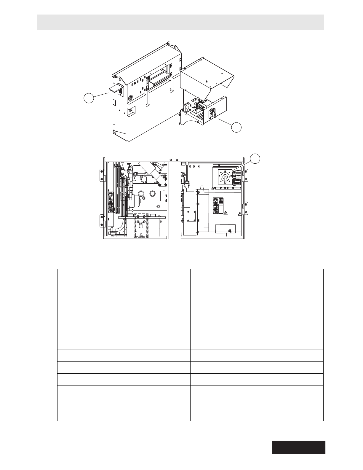
6 Operation, Control, and Component Locations
6.1 Control / Component Locations
52
wc_tx003635gb_FM10.fm
Page 53
Operation, Control, and Component Locations
s
s
t
wc_gr011690
6.2 Control Panel Components
Ref. Description Ref. Description
Main circuit breaker
a
b Voltage adjustment rheostat m GFI receptacle (120 VAC, 20A)
c Genset controller (Basler or Deep Sea) n Remote run terminal block
d Idle switch (high and low) (if equipped) o Emergency stop switch
e Ground connection point p Lug door interlock switch
f Pre-alarm/shutdown LED q Bond bar
g Engine start switch r Terminal lugs
h Hour meter s Vo ltage selector switch
j Circuit breaker (240V, 20A or 50A) t Fuse box
k Circuit breaker (120V, 20A) — —
Twist-lock receptacle
(2) 240 VAC, 50A
l
optional:
240 VAC 20A, (1) 240 VAC 50A
(2)
wc_tx003635gb_FM10.fm
53
Page 54

Operation (Basler Controller)
AUS
APAGADO
ARRET
OFF
START / LAUFEN
ARRANQUE / MARCHA
DEMARRER / MARCHE
START / RUN
E
M
E
R
G
E
N
C
Y
S
T
O
P
AUS
APAGADO
ARRET
OFF
START / LAUFEN
ARRANQUE / MARCHA
DEMARRER / MARCHE
START / RUN
7 Operation (Basler Controller)
7.1 Main Circuit Breaker
Mobile Generator
Location
Various styles of main circuit breakers may be found on Wacker Neuson Mobile
generators. The main circuit breaker (a) is located on the control panel.
Note: Graphic is representative only. Your machine may vary.
a
START / RUN
START / LAUFEN
ARRANQUE / MARCHA
DEMARRER / MARCHE
OFF
AUS
APAGADO
START / RUN
START / LAUFEN
ARRANQUE / MARCHA
DEMARRER / MARCHE
OFF
AUS
APAGADO
ARRET
ARRET
Functions
wc_gr011444
■ The main circuit breaker interrupts power from the volt age selector switch to the
terminal lugs.
■ The main circuit breaker does not interrupt power to the convenience
receptacles.
WARNING
Electric shock hazard. High voltage is present inside the control panel while the
engine is running.
► Do not open the control panel unless the engine is stopped.
NOTICE: Before shutting down the generator or performing any service to the
generator, make sure the main circuit breaker is in the OFF position.
54
wc_tx003579gb_FM10.fm
Page 55

Mobile Generator
AUS
APAGADO
ARRET
OFF
REMOTE START
FERNSTART
ARRANQUE REMOTO
DEMARRAGE A
DISTANCE
START / LAUFEN
ARRANQUE / MARCHA
DEMARRER / MARCHE
START / RUN
7.2 Engine Start Switch
Operation (Basler Controller)
Description
Function
The engine start switch (a) is a three-position switch: “REMOTE START”, “OFF”,
and “START/RUN”.
OFF
AUS
APAGADO
ARRET
REMOTE START
FERNSTART
ARRANQUE REMOTO
DEMARRAGE A
DISTANCE
START / RUN
START / LAUFEN
ARRANQUE / MARCHA
DEMARRER / MARCHE
wc_gr011436
Position Function LCD Screen
REMOTE START This position is used when the generator is
being operated as a stand-by power supply, and
it is connected to a remote switch. The
generator is in stand-by mode and will not start
until the remote switch is activated (closed).
START/RUN This is the normal start and run position. When
set to this position, power is supplied to the
genset controller which immediately launches
the start-up sequence.
As a precaution, be prepared for engine st artu p
anytime the engine start switch is in the
REMOTE START position.
a
READY screen
Monitoring
screen
wc_tx003579gb_FM10.fm
OFF Power to the genset controller is disconnected. Blank screen (off)
55
Page 56

Operation (Basler Controller)
A
Ø
HZ
V
DIAGNOSTICS
DIAGNOSEN
DIAGNOSTICOS
DIAGNOSTICS
R
Basler
Mobile Generator
7.3 Genset Pre-Alarms and Alarms (Shut-Down Conditions)
Background
Pre-alarms
Alarms/
shutdowns
The genset controller monitors variables of engine and machine function. The
genset controller is programmed to signal pre-alarm conditions, and to shut down
the machine when an alarm condition exists.
Pre-alarm conditions are:
■ Low fuel level
■ High coolant temperature
■ Low oil pressure
■ Time to maintenance
During a pre-alarm condition, the LCD panel (a) displays the type of pre-alarm, an d
the LED (b) flashes. The machine is not shut down.
Shut-down conditions are:
■ Low fuel level
■ High coolant temperature
a
■ Low oil pressure
■ Overspeed/Underspeed
■ Overcrank
■ Low coolant level (if equipped)
b
■ Overcurrent
■ Low oil level (option)
1
Not used with Isuzu engine.
1
wc_gr011837
During an alarm condition, the LCD
panel (a) displays the type of alarm, the LED (b) illuminates continuously, and the
machine is shut down.
Variable Normal Pre-Alarm Alarm To Reset
Fuel level >15% 15% 5% Fill fuel tank. Toggle start switch.
Coolant temp 85°C±8 105°C 115°C Add coolant. Toggle start switch.
Oil pressure 60–80 psi 20 psi 15 psi Add engine oil. Toggle start switch.
Overspeed 60 Hz — 66 Hz Toggle start switch.
Underspeed 60 Hz — 54 Hz Toggle start switch.
Overcrank — — After 3 attempts Toggle start switch.
Time to maintain 250 hours 0 hours — Reset genset controller.
Coolant level Above sender — Below sender Add coolant. Toggle start switch.
56
wc_tx003579gb_FM10.fm
Page 57

Mobile Generator
A
Ø
HZ
V
R
Basler
DIAGNOSTICS
DIAGNOSEN
DIAGNOSTICOS
DIAGNOSTICS
wc_gr010360
a
b
7.4 Overcurrent Condition
Along with engine functions, the genset controller continuously monitors the
current load in each leg. The values for current overload are programmed into the
ECM at the factory and are different for each generator size.
When an overcurrent condition is sensed in any leg, the pre-alarm/shutdown LED
(b) flashes and the LCD displays OVERCURRENT.
If the overcurrent condition persists, the main circuit breaker (a) opens and the
LCD screen changes to OVRLOAD - SET BRKR. This indicates an overload fault.
Operation (Basler Controller)
To clear the overload fault, reset the main circuit breaker. Failing to reset the main
circuit breaker within 5 minutes will cause the machine to shut down. The LCD
screen will then change to OVERLOAD.
wc_tx003579gb_FM10.fm
57
Page 58

Operation (Basler Controller)
wc_gr010361
AUSAUS
APAGADOAPAGADO
ARRETARRET
OFFOFF
REMOTE STARTREMOTE START
FERNSTARTFERNSTART
ARRANQUE REMOTOARRANQUE REMOTO
DEMARRAGE A DEMARRAGE A
DISTANCEDISTANCE
START / LAUFENSTART / LAUFEN
ARRANQUE / MARCHAARRANQUE / MARCHA
DEMARRER / MARCHEDEMARRER / MARCHE
START / RUNSTART / RUN
E
M
E
R
G
E
N
C
Y
S
T
O
P
A
Ø
HZ
V
R
Basler
DIAGNOSTICS
DIAGNOSEN
DIAGNOSTICOS
DIAGNOSTICS
042563
r
p
m
k
j
l
Mobile Generator
7.5 Using the Lugs and the Convenience Receptacles
Overview
Loads can be connected to the genset in two different ways:
1. At the connection lugs (r).
Located as shown, behind the lug door , the connection lugs serve as connection
points for cables.
2. At the convenience receptacles:
■ 120V/240V twist-lock receptacles (l)
■ 120V GFCI duplex receptacles (m)
Note: The convenience receptacles are not protected by the main circuit breaker.
They are protected by their own circuit breakers (j, k). Power to the convenience
receptacle circuit breakers is available any time the engine is running, even with
the main circuit breaker OFF (open).
Note: Graphic is representative only. Your machine may vary.
Lug door
interlock
switch
The lug door interlock switch (p) is located behind the lug door. The lug door
interlock switch is a safety device. When the lug door is opened, the lug door
interlock switch trips the main circuit breaker.
Note: The lug door interlock switch does NOT interrupt power to the convenience
receptacles. However, the switch does stop excitation at the generator. The result
is significantly reduced voltage at the convenience receptacles.
wc_tx003579gb_FM10.fm
58
Page 59

Mobile Generator
wc_gr011503
277/480V
120/240V
1Ø3Ø
3Ø
1Ø
DIESELDIESEL
SOLAMENTE COMBUSTIBLE DE BAJO CONTENIDO DE AZUFREO COMBUSTIBLE DE SOLAMENTE COMBUSTIBLE DE BAJO CONTENIDO DE AZUFREO COMBUSTIBLE DE
ULTRABAJO CONTENIDO DE AZUFRE.ULTRABAJO CONTENIDO DE AZUFRE.
NUR NIEDRIGEN SCHWEFELKRAFTSTOFF ODER ULTRANIEDRIGEN SCHWEFELKRAFTSTOFF.NUR NIEDRIGEN SCHWEFELKRAFTSTOFF ODER ULTRANIEDRIGEN SCHWEFELKRAFTSTOFF.
STOPSTOP
PELIGROPELIGRO
GEFAHRGEFAHR
DANGERDANGER
DANGERDANGER
177416177416
!!
!!
1Ø
120/240V
208/240V 3
Ø
3Ø
277/480V
3Ø
346/600V
120/139V 1
Ø
a
b
7.6 Selecting the Voltage
Operation (Basler Controller)
Location
Selecting the
voltage
One of two types of voltage selector switch—either three-position (a) or fourposition (b)—is mounted to the machine near the lugs.
WARNING
Electric shock hazard. High voltage is present inside the voltage selector switch
enclosure when the engine is running.
► Do not open the voltage selector switch enclosure unless the engine is stopped.
The chart below lists the ranges of voltages available in each of the switch
positions. Select the desired voltage by rotating the handle of the voltage selector
switch. Then, use the voltage adjustment rheostat to set the exact voltage you
require. The voltage is displayed on the LCD panel.
Range of Voltages Available
Switch position
3Ø at lugs
(L–L–L)
1Ø at lugs
(L–N)
1Ø at lugs
(L-L)
1Ø at twist lock
L-N (120V) L-L (240V)
1Ø at GFCI
120/240 VAC 1Ø — 110–125 220–250 110–125 220–250 110–125
208/240 VAC 3Ø
190–240 110–139 190–240 110–139 190–240 110–139
120/139 VAC 1Ø
277/480 VAC 3Ø 380–480 220–277
346/600 VAC 3Ø
1
540–600 — — — — —
1
Not available on all models.
2
Not available on 600V models.
2
190–240
2
110–139
2
190–240
2
110–139
NOTICE: Do not change the position of the voltage selector switch while the
engine is running. Doing so can cause arcing which can damage the voltage
selector switch and the generator windings.
2
wc_tx003579gb_FM10.fm
59
Page 60

Operation (Basler Controller)
AUSAUS
APAGADOAPAGADO
ARRETARRET
OFFOFF
REMOTE STARTREMOTE START
FERNSTARTFERNSTART
ARRANQUE REMOTOARRANQUE REMOTO
DEMARRAGE A DEMARRAGE A
DISTANCEDISTANCE
START / LAUFENSTART / LAUFEN
ARRANQUE / MARCHAARRANQUE / MARCHA
DEMARRER / MARCHEDEMARRER / MARCHE
START / RUNSTART / RUN
E
M
E
R
G
E
N
C
Y
S
T
O
P
A
Ø
HZ
V
R
Basler
DIAGNOSTICS
DIAGNOSEN
DIAGNOSTICOS
DIAGNOSTICS
042563
wc_gr011502
c
A
Ø
HZ
V
R
Basler
DIAGNOSTICS
DIAGNOSEN
DIAGNOSTICOS
DIAGNOSTICS
AUSAUS
APAGADOAPAGADO
ARRETARRET
OFFOFF
REMOTE STARTREMOTE START
FERNSTARTFERNSTART
ARRANQUE REMOTOARRANQUE REMOTO
DEMARRAGE A DEMARRAGE A
DISTANCEDISTANCE
START / LAUFENSTART / LAUFEN
ARRANQUE / MARCHAARRANQUE / MARCHA
DEMARRER / MARCHEDEMARRER / MARCHE
START / RUNSTART / RUN
Mobile Generator
Using the
rheostat
The voltage adjustment rheostat (c) is used to fine-tune the voltage as needed
while the machine is running.
Care must be taken when using the voltage adjustment rhe ostat because adjusting
the voltage for 3-phase operation affects the voltage available at the single-phase
outlets. As the 3-phase voltage increases, so does the single-phase voltage.
NOTICE: Do not use the GFCI or twist-lock receptacle (120V) when the 1Ø vo ltage
is above 135V. Damage to the receptacle and the tools connected to it may occur.
Switch Position
208 VAC 3Ø
120 VAC 1Ø
3Ø Voltage
(L-L-L)
208 208 120 120
220 220 125 125
240 240
277/480 VAC 3Ø 480 240 139
460 230 133
346/600 VAC 3Ø
3
600
540
Corresponding 1Ø voltage
Twist lock receptacle
L-L (240V) L-N (120V) 120V GFCI
139
1
1
2
139
139
133
1
1
2
1
Do not use receptacle with this voltage.
2
Voltage may be too high for some tools and equipment. Check tool/equipment specifications.
3
Not available on all models.
wc_tx003579gb_FM10.fm
60
Page 61

Mobile Generator
7.7 Before Starting the Machine
WARNING
Personal injury hazard. Failure to follow the listed procedures may cause injury to
personnel or damage to the generator.
► Make sure that all persons setting up the generator are certified or fully trained
on the installation of the generator.
Before putting the generator into service, perform each item on the following
checklist.
Operation (Basler Controller)
Exterior
checks
Internal
checks
Pre-operation
checks
Check for damage that may have occurred during towing or travel to the jobsite.
Repair any damage.
Make sure that the generator is level.
Chock the trailer wheels.
Check engine oil, coolant, and fuel levels—fill as required.
Check the fan belt and hoses on the engine for loose connections or fraying—
tighten or replace belts and hoses as required.
Remove any debris that has lodged in vents, near the radiator, or around the
fan.
Make sure the exhaust compartment is clean, with nothing touching the muffler
or exhaust pipes.
Read and understand the engine owner’s manual.
Check local regulations and NEC standards for electrical connections.
Determine voltage needs; obtain proper cable and equipment to meet the
needs. Follow local regulations and NEC standards.
Make sure that the generator is grounded to a good earthen ground per local
regulations and NEC standards.
Review and follow the safety instructions found in the front of this Operator’s
Manual.
wc_tx003579gb_FM10.fm
61
Page 62

Operation (Basler Controller)
wc_gr011279
AUAUSS
APAGADAPAGADOO
ARREARRETT
OFOFFF
REMOTE STARREMOTE STARTT
FERNSTARFERNSTARTT
ARRANQUE REMOTARRANQUE REMOTOO
DEMARRAGE ADEMARRAGE A
DISTANCDISTANCEE
START / LAUFESTART / LAUFENN
ARRANQUE / MARCHARRANQUE / MARCHAA
DEMARRER / MARCHDEMARRER / MARCHEE
START / RUSTART / RUNN
AUAUSS
APAGADAPAGADOO
ARREARRETT
OFOFFF
REMOTE STARREMOTE STARTT
FERNSTARFERNSTARTT
ARRANQUE REMOTARRANQUE REMOTOO
DEMARRAGE ADEMARRAGE A
DISTANCDISTANCEE
START / LAUFESTART / LAUFENN
ARRANQUE / MARCHARRANQUE / MARCHAA
DEMARRER / MARCHDEMARRER / MARCHEE
START / RUSTART / RUNN
A
Ø
HZ
V
R
Basler
DIAGNOSTICS
DIAGNOSEN
DIAGNOSTICOS
DIAGNOSTICS
042563
1Ø
120/240V
3Ø
277/480V
208/240V 3
Ø
3Ø
346/600V
120/139V 1
Ø
e
c
d
a
b
f
7.8 Starting and Running the Machine
CAUTION
Possibility of injury or equipment damage. Failure to match phase, voltage, and
frequency may cause equipment connected to the generator to operate incorrectly.
► When using the generator as a stand-by or substitute power supply, make sure
the phase, voltage, and frequency of the generator matches that of the utility
lines or of any other power source normally used.
Mobile Generator
Preliminary
Perform the procedure below to start and run the machine.
1. Set the engine start switch (a) to the OFF position.
Note: Graphic is representative only. Your machine may vary.
2. Set the main circuit breaker (b) to OFF.
3. Set the convenience receptacle circuit breakers (c, d) to OFF.
4. Turn off all loads.
5. Check position of the voltage selector switch (e) and make sure it is set for the
desired voltage output. Lock the voltage selector switch in place if desired.
This procedure continues on the next page.
62
wc_tx003579gb_FM10.fm
Page 63

Mobile Generator
Continued from the previous page.
6. Connect the load to the lugs and/or to the convenience receptacles.
7. Check the operation of the genset controller.
a.Set the engine start switch to REMOTE START. The LCD panel momentarily
displays INITIALIZING followed by READY. Engine information is also
displayed. Check the fuel level and battery voltage. Add fuel and/or charge
the battery if needed. If the LCD display does not power up, check battery
voltage and connections.
b.With the READY screen showing, press the emergency stop button (f). The
LCD panel displays EMERGENCY STOP, and the pre-alarm/alarm LED
illuminates. If the LCD does not display EMERGENCY STOP, do not
continue. Contact a Wacker Neuson dealer for assistance. Pull out the
emergency stop button after verifying the display.
c.Set the engine start switch to OFF.
Operation (Basler Controller)
Starting
Upon startup
8. Start the engine by setting the engine start switch to the START/RUN position.
After displaying INITIALIZING and NOT IN AUTO, the LCD panel will display
START DELAY followed by CRANKING as the engine begins its crank cycle. The
crank cycle calls for the engine to crank for 10 seconds, then rest for 10 seconds.
This cycle will repeat three times in an attempt to start the engine.
If the engine does not start within three attempts, the genset controller stops the
crank cycle and OVERCRANK is displayed on the LCD panel.
9. To repeat the crank cycle, set the start switch to OFF, then back to ST AR T/RUN.
Upon engine startup, the LCD displays the monitoring screen. Run the engine for a
few minutes to allow it to warm before turning on (closing) any circuit breakers.
Note: Leave the engine start switch (a) in the START/RUN position while the
generator is operating.
10.Check the voltage on the monitoring screen and adjust it as needed using the
voltage adjustment rheostat. See topic Selecting the Voltage.
11.Turn on (close) the appropriate circuit breakers for your load.
wc_tx003579gb_FM10.fm
wc_gr010195
63
Page 64
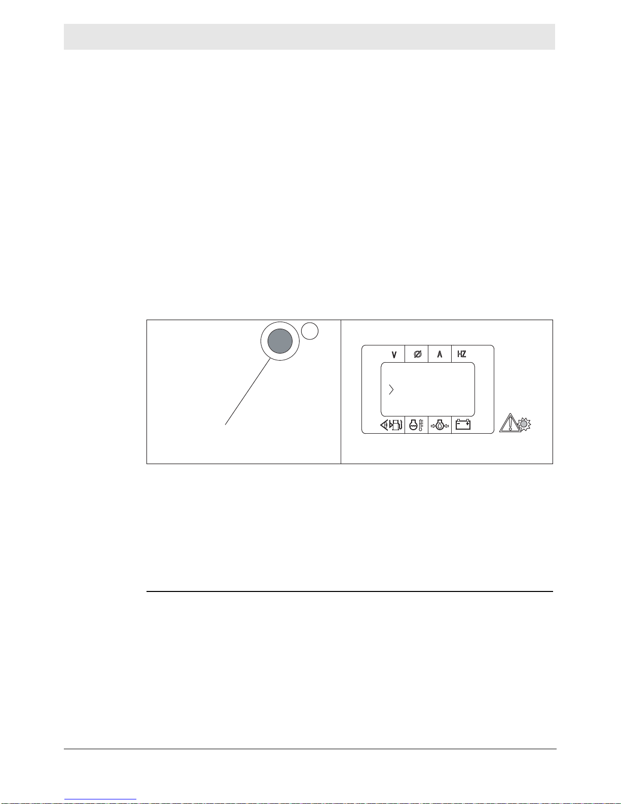
Operation (Basler Controller)
ALARM ACTIVEALARM ACTIVE
TO VIEWTO VIEW
EMERGENCY STOPEMERGENCY STOP
a
E
M
E
R
G
E
N
C
Y
wc_gr010365
7.9 Stopping the Machine
Check with other personnel on the jobsite and let them know that power is being
turned off. Make sure that the power shutdown will not create any hazards by
turning off devices such as pumps, heaters, or lights that may need to be kept on.
1. Turn off all loads connected to the generator.
2. Set the main circuit breaker to OFF.
3. Set the convenience receptacle circuit breakers to OFF.
4. Let the engine run for approximately five minutes to cool it down.
5. Move the engine start switch to the OFF position.
7.10 Emergency Stop Switch
Mobile Generator
Location
Function
The emergency stop switch (a) is the red button located as shown, and can be
accessed with the panel doors closed.
Activate the emergency stop switch by pushing the red button. Pushing the
emergency stop switch:
■ turns off (opens) the main circuit breaker
■ cuts power to the fuel solenoid
■ stops the engine
■ causes “Alarm Active: Emergency Stop” to appear on the LCD display
The emergency stop switch will remain activated until the button is pulled out.
NOTICE: Do not use the emergency stop switch to shut down the generator during
normal operation. The emergency stop switch is intended for use only in an actual
emergency situation where the generator must be stopped immediately.
To shut down the generator during normal operation, turn off (open) the main circuit
breaker and then move the engine start switch to the OFF position.
wc_tx003579gb_FM10.fm
64
Page 65

Mobile Generator
Operation (Basler Controller)
7.11 LCD Panel: Monitoring Machine Operation
Overview
Generator
information
Generator and engine information is continuously monitored and displayed on the
LCD panel. The upper line displays generator information. The lower line displays
engine information.
Generator
Engine
wc_gr010202
The upper line of the LCD panel shows the voltage, phase, amperage, and
frequency of the electric power being generated. The information is shown only
when the engine is running.
Symbol Meaning Description
V Volts Displays the value of the AC output voltage being
produced by the generator.
Ø Phase Displays the leg or phase currently being monitored. In
three-phase mode, the display toggles between P1, P2,
and P3. In single-phase mode, the display toggles
between L1, L3, and L-L.
A Amps Displays the value of the AC output amperage
produced by the generator. If the generator is operating
at no load, output amperage will be zero (0).
HZ Frequency in
Hertz
Displays the value of the output frequency.
For tier 3 engines, this display will read approximately
61.5 Hz under a no-load condition and approximately
60 Hz under load.
For tier 4 engines, this display will read approximately
60.0 Hz under no-load and loaded conditions.
This procedure continues on the next page.
wc_tx003579gb_FM10.fm
65
Page 66

Operation (Basler Controller)
Continued from the previous page.
Mobile Generator
Engine
information
The lower line of the LCD panel shows fuel level, temperature, oil pressure, and
battery voltage. The information is shown when the engine start switch is set to
REMOTE START or RUN/START.
Symbol Meaning Description
Fuel level Indicates relative fuel level in the fuel tank
Temperature Displays temperature of engine coolant
Oil pressure Displays engine oil pressure between 0–100 psi
Normal operating pressure = 50–80 psi
Battery voltage Displays real-time battery voltage while the machine
is operating
Actual battery voltage is displayed when the engine
switch is set to REMOTE START and the generator
is in standby mode.
66
wc_tx003579gb_FM10.fm
Page 67

Mobile Generator Working with Basler Controller
wc_gr010130
a
b
1
2
3
4
56
8 Working with Basler Controller
8.1 How to Use the Genset Controller LCD and Keypad
Basics
Actions of the
buttons
The LCD (a) is used to display information regarding machine performance and
operating status. The keypad (b) is used to maneuver through the various menus
of the genset controller. The keypad is also used to enter and change values of
machine settings.
To scroll through the options within a menu, use the up/down arrow buttons (2, 3).
When an option on a menu is highlighted, it can be accessed for further submenus.
To do so, press the right arrow button (1).
Normal
screens
To return to a previous screen, press the left arrow button (4).
To exit menu navigation and return to monitoring status (or the READY screen),
press and hold the left arrow button.
To access a setting in order to change it, press the check mark button (5).
To cancel an operation, press the “X” reset button (6).
The machine must be running, or the start switch set to REMOTE START position,
for the genset to be on and active. Sample screens of normal operation are shown
below.
Genset monitoring status READY screen
This screen is displayed
when the machine is running.
This screen is displayed when the
start switch is in REMOTE START.
wc_gr010144
wc_tx003229gb_FM10.fm
67
Page 68

Working with Basler Controller
Metering
Settings
Metering
Engine
Oil Pressure
Coolant Temp
Fuel Level
Engine Load
Coolant Level*
Total Run Time
Settings
General Settings
Communications
Generator Protection
Breaker Management
Bias Control
Enter Password
General Settings
Crank Settings
Alarm-Status
Alarms
Pre-Alarms
Status
Inputs
Event Log
J1939 Engine Config*
J1939 Active DTC*
J1939 Previous DTC*
Session
Generator
Bus V
Bus Frequency
Synchronizer
Session
Session Info
Total Run Time
Loaded Run Time
Unloaded Run Time
Cumulative
Unloaded Run Time
Front Panel HMI
Detailed Data
Detailed Data
* NOT AVAILABLE ON SOME MODELS
wc_gr007618
8.2 Menu Diagram of the Genset Controller
The various menus of the genset controller are divided into two main categories:
METERING and SETTINGS. Access to the METERING menu and to the
SETTINGS menu is done through the MAIN MENU. To access the MAIN MENU
from either the monitoring screen or the READY screen, press the right arrow
button.
Note: Graphic is representative only. Your machine may vary.
.
Mobile Generator
68
wc_tx003229gb_FM10.fm
Page 69

Mobile Generator Working with Basler Controller
8.3 Menu Diagram Components
.
Menu Item Description Menu Item Description
Alarm Config
Alarm Configuration
Alarms
Alarm–Status
Amps
Back
Battery Volt
Bias Control
Breaker Management
Bus Frequency
Bus V
Communications
Conf Elements
Conf Prot Status
Configure Date/Time
Coolant Level
Coolant Temp
Cooldown Time
Crank Settings
Cumulative
Cumulative Info
Detailed Data
Diagnostic Menu Navi-
gation
Down
Engine
En
Enter Password
Event Log
Forward
Frequency
Front Panel HMI
Fuel Level
General Settings
gine
Load
Alarm configuration
—
—
—
—
—
—
—
—
—
Bus voltage
—
Configurable elements
Configurable protection
status
—
—
—
—
—
—
—
—
—
—
—
—
—
—
—
—
Human-Machine
Interface
—
—
J1939 Active DTC
J1939 Data
J1939 Engine Config
J1939 Previous DTC
kVA
kVAR
kW
Language
LCD Contrast
Loaded Run Time
Low Fuel Level
Main Menu
Maintenance Reset
Metering
Oil Pressure
Outputs
PF
Power
Pre-Alarms
Programmable Inputs
RPM
Run Statistics
Session
Session Info
Settings
Speed Source
Status
Synchronizer
Sys Parameters
System Settings
System Units
Total Run Time
Unloaded Run Time
Diagnostic Trouble
Codes
—
Engine configuration
Diagnostic Trouble
Codes
Kilovolt-amps
Kilovolt-amps Reactive
Kilowatts
—
Liquid Crystal Display
—
—
—
—
—
—
—
Power factor
—
—
—
Rotations per minute
—
—
—
—
—
—
—
System parameters
—
—
—
—
wc_tx003229gb_FM10.fm
69
Page 70

Working with Basler Controller
Menu Item Description Menu Item Description
Generator
Generator Protection
Hrs to Maintenance
Inputs
—
—
Hours to maintenance
—
Up
Voltages
—
—
Mobile Generator
—
—
—
—
8.4 Using the Metering and Settings Menus
Background
METERING
menus
SETTINGS
menus
The various menus of the genset controller are divided into two main categories:
METERING, and SETTINGS. Access to the METERING menu and to the
SETTINGS menu is done through the MAIN MENU.
METERING menus give detailed information regarding engine status and
generator performance. The machine must be running for many of the parameters
to be active. Use the menu diagram of the genset controller as a guide for
navigating the menus.
Parameters under the METERING menu are read-only. They cannot be changed,
except for HRS to MAINTENANCE parameter, which can be reset.
SETTINGS menus give detailed information regarding genset controller
configuration. Use the menu diagram of the genset controller as a guide for
navigating the menus.
There are a limited number of parameters under the SETTINGS menus that may
be changed by the user. These parameters are:
LCD screen contrast
Time and date
Sender fail time delays
Units of measure (imperial or metric)
Low fuel pre-alarm level
Low fuel alarm level
Cooldown time
Pre-crank time delay
Maintenance interval
Procedures for changing these parameters are included in this manual.
70
wc_tx003229gb_FM10.fm
Page 71

Mobile Generator Working with Basler Controller
wc_gr010119
8.5 Logging in to the Genset Controller by Entering the Password
Precaution
Password
At ENTER
PASSWORD
Only change parameters when the READY screen is displayed (start switch in the
REMOTE START position).
In order to change the parameters under the settings menu, you must be “logged
in” to the genset controller. There are two displays where you can log in to the
genset controller: 1) at the “ENTER PASSWORD” display under SETTINGS; or 2)
when prompted for the password by the genset controller at the parameter you
want to change.
The default password, in either case, is “OP”. It is set at the factory. It is the only
password available, and it cannot be changed.
Once you are logged in, you will remain logged in until:
you log out,
the machine is turned off,
or if you press the check mark button inadvertently. This usually happens when
attempting to change a locked parameter.
To log in to the genset controller at the ENTER PASSWORD display, do the
following:
1. Press the right arrow button (1) to enter the main menu.
2. Use the up/down arrow buttons (2, 3) to highlight SETTINGS. Then, press the
right arrow button.
This procedure continues on the next page.
wc_tx003229gb_FM10.fm
71
Page 72

Working with Basler Controller
wc_gr010122
Continued from the previous page.
3. Using the up/down arrow buttons, scroll through the setting parameters until
ENTER PASSWORD is highlighted. Then, press the check mark button (5).
4. The password entry screen appears with a letter “A” as the default character.
Use the up/down arrow buttons to change the “A” to “O”. Then, press the right
arrow button to move the cursor to the next position.
Mobile Generator
5. Use the up/down buttons to select “P”. Then, press the check mark button.
The screen below appears. You are now logged in and have the ability to change
parameter settings. Do not re-enter the password even though it is requested;
instead, navigate to the parameter you would like to change. You may, however,
log out if desired. To do so, navigate to LOGOUT and press the check mark button.
wc_tx003229gb_FM10.fm
72
Page 73

Mobile Generator Working with Basler Controller
wc_gr010128
At the
PASSWORD
prompt
To log in when prompted to enter the password, do the following:
1. The password entry screen appears with a letter “A” as the default character.
Use the up/down arrow buttons to change the “A” to “O”. Then, press the right
arrow button to move the cursor to the next position.
2. Use the up/down arrow buttons to select “P”. Then, press the check mark
button.
3. A screen for the parameter , similar to tha t shown below lef t (A), will appear. The
word “~~EDIT~~” will be displayed. Whenever “~~EDIT~~” is displayed, it
means that you are able to change the parameter. Use the up/down arrow
buttons to change the setting. Then, press the check mark button to accept the
new value.
Note: If the genset controller displays the screen (B), it means that the parameter
cannot be changed by the operator. Do not re-enter the p assword even though you
are requested to do so; instead, press the “X” button to cancel the operation and
return to the previous screen. If you do re-enter the password (by pressing the
check mark button), you will be logged out. In such cases, turn the machine off,
then back on again, and restart the procedure from the beginning.
wc_tx003229gb_FM10.fm
73
Page 74

Working with Basler Controller
8.6 Adjusting the LCD Screen Contrast
Mobile Generator
Requirements
Procedure
Machine stopped
Start switch in REMOTE START
Note: Internal programming of the genset controller, or closed connections to a
remote start switch, may cause the machine to start unexpectedly. Be prepared for
the engine to start even with the engine start switch in the REMOTE START
position.
Perform the procedure below to adjust the LCD screen contrast.
1. Press the right arrow button (1) to access the MAIN MENU.
2. Using the up/down arrow buttons (2, 3) highlight SETTINGS. Then, press the
right arrow button.
3. Highlight GENERAL SETTINGS. Then, press the right arrow button (1).
4. Highlight FRONT PANEL HMI. Then, press the right arrow button.
5. Highlight LCD CONTRAST. Then, press the check mark button (5).
6. If you are not logged in, enter the password “OP”. Press the check mark button.
7. Using the up/down arrow buttons, change the contrast value as desired. Press
the check mark button when finished.
8. Exit by pressing the left arrow button (4) twice or until the LCD displays the
SETTINGS menu. Then, scroll to LOGOUT and press the check mark button.
Press the left arrow button until the READY screen appears.
Result
The screen contrast has now been adjusted.
74
wc_tx003229gb_FM10.fm
Page 75

Mobile Generator Working with Basler Controller
wc_gr010133
8.7 Changing the Time/Date Settings
Requirements
Procedure
Machine stopped
Start switch in REMOTE START
Note: Internal programming of the genset controller, or closed connections to a
remote start switch, may cause the machine to start unexpectedly. Be prepared for
the engine to start even with the engine start switch in the REMOTE START
position.
Perform the procedure below to change the time and date.
1. Press the right arrow button (1) to access the MAIN MENU.
2. Using the up/down arrow buttons (2, 3) highlight SETTINGS. Then, press the
right arrow button.
3. Highlight GENERAL SETTINGS. Then, press the right arrow button (1).
4. Highlight CONFIGURE DATE/TIME. Then, press the right arrow button.
5. Highlight the setting you want change. Then, press the check mark button (5).
6. If you are not logged in, enter the password “OP”. Press the check mark button.
7. Using the up/down arrow buttons, change the value as desired. Press the check
mark button when finished.
8. Exit by pressing the left arrow button (4) twice or until the LCD displays the
SETTINGS menu. Then, scroll to LOGOUT and press the check mark button.
Press the left arrow button so that the READY screen appears.
Result
wc_tx003229gb_FM10.fm
The date/time settings have now been changed.
75
Page 76
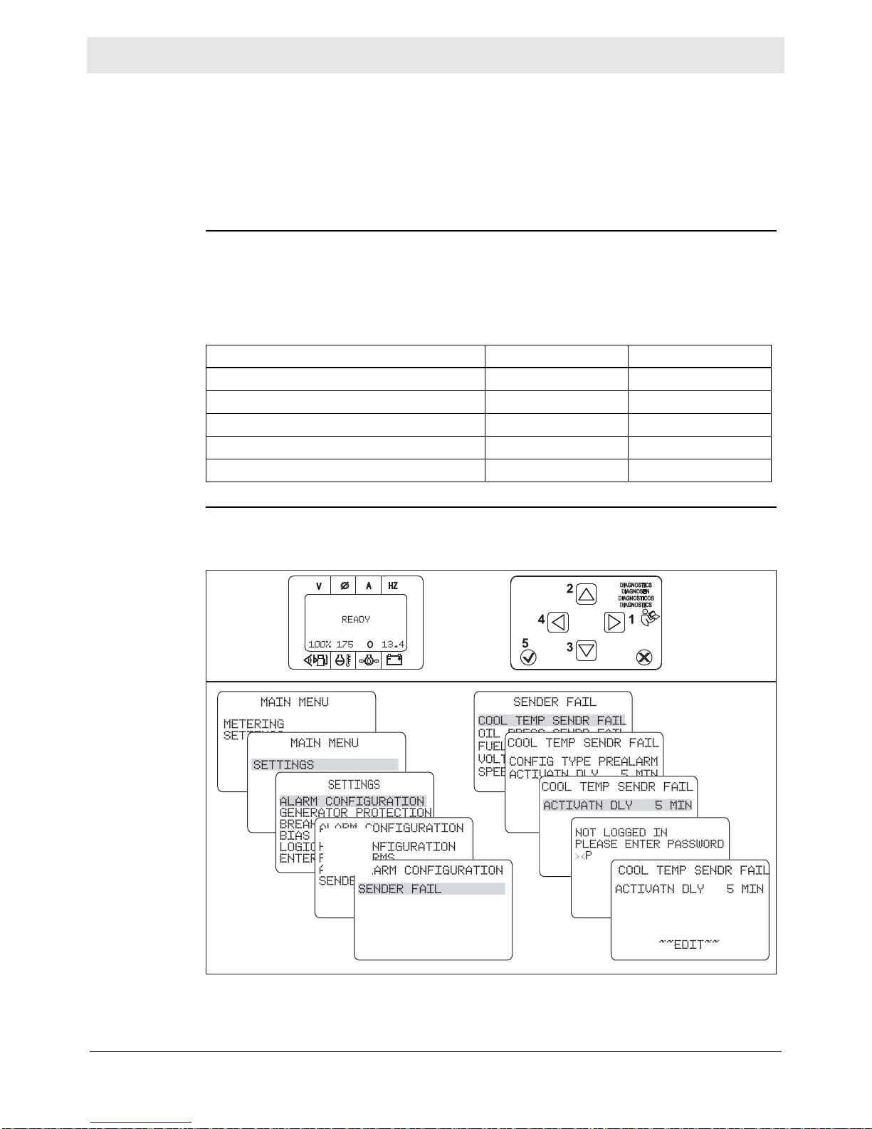
Working with Basler Controller
8.8 Changing the Sender Fail Time Delays
Mobile Generator
Requirements
Background
Procedure
Machine stopped
Start switch in REMOTE START
Note: Internal programming of the genset controller or connections to a remote
start switch may cause the machine to start unexpectedly. Be prepared for the
engine to start even with the engine start switch in the REMOTE START position.
There are five senders/sensors monitored by the genset controller. Each has its
own failure-time-delay period. This is the amount of time that the genset controller
must experience the failure before the failure will be seen on the LCD display.
These failure-time-delay periods may be changed. The table below list s the fa ilu retime-delay periods, the allowable range, and their factory settings.
Failure Time Delay Range Factory Setting
Coolant temperature sender 0 to 30 min 5 min
Oil pressure sender 0 to 300 sec 10 sec
Fuel level sender 0 to 300 sec 10 sec
Voltage sensor 0 to 300 sec 15 sec
Speed sender 0 to 300 sec 300 sec
Perform the procedure below to change a fail time delay.
1. Press the right arrow button (1) to access the MAIN MENU.
This procedure continues on the next page.
wc_gr010134
wc_tx003229gb_FM10.fm
76
Page 77

Mobile Generator Working with Basler Controller
Continued from the previous page.
2. Using the up/down arrow buttons (2, 3) highlight SETTINGS. Then, press the
right arrow button.
3. Highlight ALARM CONFIGURATION. Then, press the right arrow button.
4. Highlight SENDER FAIL. Then, press the right arrow button.
5. Highlight the sender or sensor you want to change. Then, press the right arrow
button.
6. Highlight ACTIVATN DELAY or TIME DELAY. Then, press the check mark
button (5).
7. If you are not logged in, enter the password “OP”. Press the check mark button.
8. Using the up/down arrow buttons, change the value as desired. Press the check
mark button when finished.
9. Exit by pressing the left arrow button (4) three times or until the LCD displays
the SETTINGS menu. Then, scroll to LOGOUT and press the check mark
button. Press the left arrow button so that the READY screen appears.
Result
The fail time delay has now been changed.
wc_tx003229gb_FM10.fm
77
Page 78

Working with Basler Controller
8.9 Changing the Units of Measure
Mobile Generator
Requirements
Background
Procedure
Machine stopped
Start switch in REMOTE START
Note: Internal programming of the genset controller, or closed connections to a
remote start switch, may cause the machine to start unexpectedly. Be prepared for
the engine to start even with the engine start switch in the REMOTE START
position.
Genset controller units of measure may be set to English (imperial) or metric.
Perform the procedure below to set the units of measure.
1. Press the right arrow button (1) to access the MAIN MENU.
2. Using the up/down arrow buttons (2, 3) highlight SETTINGS. Then, press the
right arrow button.
3. Highlight SYSTEM PARAMS. Then, press the right arrow button.
4. Highlight SYSTEM SETTINGS. Then, press the right arrow button.
5. Highlight the SYSTEM UNITS. Then, press the check mark button (5).
6. If you are not logged in, enter the password “OP”. Press the check mark button.
7. Using the up/down arrow buttons, change the value as de sired. Press the check
mark button when finished.
This procedure continues on the next page.
78
wc_tx003229gb_FM10.fm
Page 79

Mobile Generator Working with Basler Controller
Continued from the previous page.
8. Exit by pressing the left arrow button (4) twice or until the LCD displays the
SETTINGS menu. Then, scroll to LOGOUT and press the check mark button.
Press the left arrow button so that the READY screen appears.
Result
The units of measure have now been changed.
wc_tx003229gb_FM10.fm
79
Page 80

Working with Basler Controller
8.10 Changing the Low Fuel Pre-Alarm Setting
Mobile Generator
Requirements
Background
Procedure
Machine stopped
Start switch in REMOTE START
Note: Internal programming of the genset controller, or closed connections to a
remote start switch, may cause the machine to start unexpectedly. Be prepared for
the engine to start even with the engine start switch in the REMOTE START
position.
The low fuel pre-alarm setting may be changed if desired. The value shown b y the
genset controller is the percentage of fuel remaining in the fuel tank. The range
allowed by the genset controller is 10–100.
Perform the procedure below to change the low fuel pre-alarm setting.
1. Press the right arrow button (1) to access the MAIN MENU.
2. Using the up/down arrow buttons (2, 3) highlight SETTINGS. Then, press the
right arrow button.
3. Highlight ALARM CONFIGURATION. Then, press the right arrow button.
4. Highlight PRE-ALARMS. Then, press the right arrow button.
5. Highlight the LOW FUEL LEVEL. Then, press the right arrow button.
6. Highlight the THRESHOLD. Then, press the check mark button (5).
7. If you are not logged in, enter the password “OP”. Press the check mark button.
This procedure continues on the next page.
80
wc_tx003229gb_FM10.fm
Page 81

Mobile Generator Working with Basler Controller
Continued from the previous page.
8. Using the up/down arrow buttons, change the value as desired. Press the check
mark button when finished.
9. Exit by pressing the left arrow button (4) three times or until the LCD displays
the SETTINGS menu. Then, scroll to LOGOUT and press the check mark
button. Press the left arrow button so that the READY screen appears.
Result
The low fuel pre-alarm setting has now been changed.
wc_tx003229gb_FM10.fm
81
Page 82

Working with Basler Controller
Mobile Generator
8.11 Changing or Disabling the Low Fuel Alarm Setting
Requirements
Background
Notes
Machine stopped
Start switch in REMOTE START
Note: Internal programming of the genset controller, or closed connections to a
remote start switch, may cause the machine to start unexpectedly. Be prepared for
the engine to start even with the engine start switch in the REMOTE START
position.
The LCD panel displays, in percentage, how much fuel is in the fuel tank. The low
fuel alarm shutdown is set at the factory to activate at 6%. This value may be
changed if desired. For example, you may wish to reduce the low fuel alarm setting
so that the machine operates for a longer period of time or until virtually all fuel is
consumed before the genset controller shuts down the machine for lack of fuel.
The range allowed by the genset controller is 0–100%.
Do not set the low fuel alarm to a value greater than that of the low fuel pre-
alarm. Doing so will nullify the function of the low fuel pre-alarm.
Setting the low fuel alarm below 5, in effect, disables the low fuel alarm. The
genset controller will not shut down the machine. The machine will shut down
when all fuel is consumed.
“5” is the lowest value the LCD will display.
NOTICE: If the low fuel alarm is set belo w 5, it is possible to run the fuel so low that
air will be drawn into the engine. The fuel system may then need to be bled before
it will start and run.
Procedure
Approximate run time (at 100% prime load) gained with low fuel alarm set to 0%.
Machine Fuel Use gal/hr Time Gained hr
G 25 1.8 3.7
G 25 ERT 1.8 4.2
G 50 3.4 3.0
G 50 ERT 3.4 3.8
G 70 4.9 2.1
G 70 ERT 4.9 2.6
G 100 6.2 3.3
G 120 7.44 2.7
G 150 8.85 3.4
G 180 10.8 2.7
G 240 13.5 2.1
Perform the procedure below to change the low fuel alarm setting.
1. Press the right arrow button (1) to access the MAIN MENU.
This procedure continues on the next page.
82
wc_tx003229gb_FM10.fm
Page 83

Mobile Generator Working with Basler Controller
Continued from the previous page.
Result
2. Using the up/down arrow buttons (2, 3) highlight SETTINGS. Then, press the
right arrow button.Highlight ALARM CONFIG. Then, press the right arrow
button.
3. Highlight ALARMS. Then, press the right arrow button.
4. Highlight the LOW FUEL LEVEL. Then, press the right arrow button.
5. Highlight the THRESHOLD. Then, press the check mark button (5).
6. If you are not logged in, enter the password “OP”. Press the check mark button.
7. Using the up/down arrow buttons, change the value as desired. Press the check
mark button when finished.
8. Exit by pressing the left arrow button (4) three times or until the LCD displays
the SETTINGS menu. Then, scroll to LOGOUT and press the check mark
button. Press the left arrow button so that the READY screen appears.
The low fuel alarm setting has now been changed.
wc_tx003229gb_FM10.fm
83
Page 84

Working with Basler Controller
8.12 Changing the Cooldown Time Setting
Mobile Generator
Requirements
Background
Procedure
Machine stopped
Start switch in REMOTE START
Note: Internal programming of the genset controller, or closed connections to a
remote start switch, may cause the machine to start unexpectedly. Be prepared for
the engine to start even with the engine start switch in the REMOTE START
position.
The genset controller includes a cooldown timer. The function of the cooldown
timer is to run the engine at no load after a period of being run at load. It is used in
conjunction with the remote start system. The cooldown timer activates when the
machine is no longer receiving a remote run signal. This timer is factory set to zero
(0) minutes. The cooldown time can be changed if desired.
Perform the procedure below to change the cooldown time setting.
1. Press the right arrow button (1) to access the MAIN MENU.
2. Using the up/down arrow buttons (2, 3) highlight SETTINGS. Then, press the
right arrow button.
3. Highlight SYSTEM PARAMS. Then, press the right arrow button.
This procedure continues on the next page.
84
wc_tx003229gb_FM10.fm
Page 85

Mobile Generator Working with Basler Controller
Continued from the previous page.
4. Highlight CRANK SETTINGS. Then, press the right arrow button.
5. Highlight COOLDOWN TIME. Then, press the check mark button (5).
6. If you are not logged in, enter the password “OP”. Press the check mark button.
7. Using the up/down arrow buttons, change the value as desired. Press the check
mark button when finished.
8. Exit by pressing the left arrow button (4) twice or until the LCD displays the
SETTINGS menu. Then, scroll to LOGOUT and press the check mark button.
Press the left arrow button so that the READY screen appears.
Result
The cooldown time setting has now been changed.
wc_tx003229gb_FM10.fm
85
Page 86

Working with Basler Controller
Mobile Generator
8.13 Changing the Pre-Crank Time Delay (Glow Plug Timer)
Requirements
Background
Procedure
Machine stopped
Start switch in REMOTE START
Note: Internal programming of the genset controller, or closed connections to a
remote start switch, may cause the machine to start unexpectedly. Be prepared for
the engine to start even with the engine start switch in the REMOTE START
position.
The genset controller includes a pre-crank time delay. This is the time the glow
plugs will be on before the engine starts to crank. The factory setting is 5 seconds.
The pre-crank time delay can be changed if desired.
NOTICE: Do not set the glow plug timer to a value of more than 10 . Damage to the
glow plugs may occur.
Perform the procedure below to change the pre-crank time delay.
1. Press the right arrow button (1) to access the MAIN MENU.
2. Using the up/down arrow buttons (2, 3) highlight SETTINGS. Then, press the
right arrow button.
3. Highlight SYSTEM PARAMS. Then, press the right arrow button.
This procedure continues on the next page.
86
wc_tx003229gb_FM10.fm
Page 87

Mobile Generator Working with Basler Controller
Continued from the previous page.
4. Highlight CRANK SETTINGS. Then, press the right arrow button.
5. Highlight PRECRANK DELY. Then, press the check mark button (5).
6. If you are not logged in, enter the password “OP”. Press the check mark button.
7. Using the up/down arrow buttons, change the value as desired. Press the check
mark button when finished.
8. Exit by pressing the left arrow button (4) twice or until the LCD displays the
SETTINGS menu. Then, scroll to LOGOUT and press the check mark button.
Press the left arrow button until the READY screen appears.
Result
The pre-crank time delay has now been changed.
wc_tx003229gb_FM10.fm
87
Page 88

Working with Basler Controller
8.14 Changing the Maintenance Interval
Mobile Generator
Requirements
Background
Procedure
Machine stopped
Start switch in REMOTE START
Note: Internal programming of the genset controller, or closed connections to a
remote start switch, may cause the machine to start unexpectedly. Be prepared for
the engine to start even with the engine start switch in the REMOTE START
position.
The maintenance interval is the time, in hours, scheduled between critical
maintenance tasks (such as, changing the engine oil). The amount of time may be
changed if desired. The factory setting is 250.
Note: Refer to the Periodic Maintenance Schedule in the Operator’s Manual for
timing of all scheduled maintenance tasks.
Perform the procedure below to change the maintenance interval.
1. Press the right arrow button (1) to access the MAIN MENU.
2. Using the up/down arrow buttons (2, 3) highlight SETTINGS. Then, press the
right arrow button.
This procedure continues on the next page.
88
wc_tx003229gb_FM10.fm
Page 89

Mobile Generator Working with Basler Controller
Continued from the previous page.
3. Highlight ALARM CONFIGURATION. Then, press the right arrow button.
4. Highlight PRE-ALARMS. Then, press the right arrow button.
5. Highlight the MAINTENANCE INTERVAL. Then, press the right arrow button.
6. Highlight the THRESHOLD. Then, press the check mark button (5).
7. If you are not logged in, enter the password “OP”. Press the check mark button.
8. Using the up/down arrow buttons, change the value as desired. Press the check
mark button when finished.
9. Exit by pressing the left arrow button (4) three times or until the LCD displays
the SETTINGS menu. Then, scroll to LOGOUT and press the check mark
button. Press the left arrow button so that the READY screen appears.
Result
The maintenance interval has now been changed.
wc_tx003229gb_FM10.fm
89
Page 90
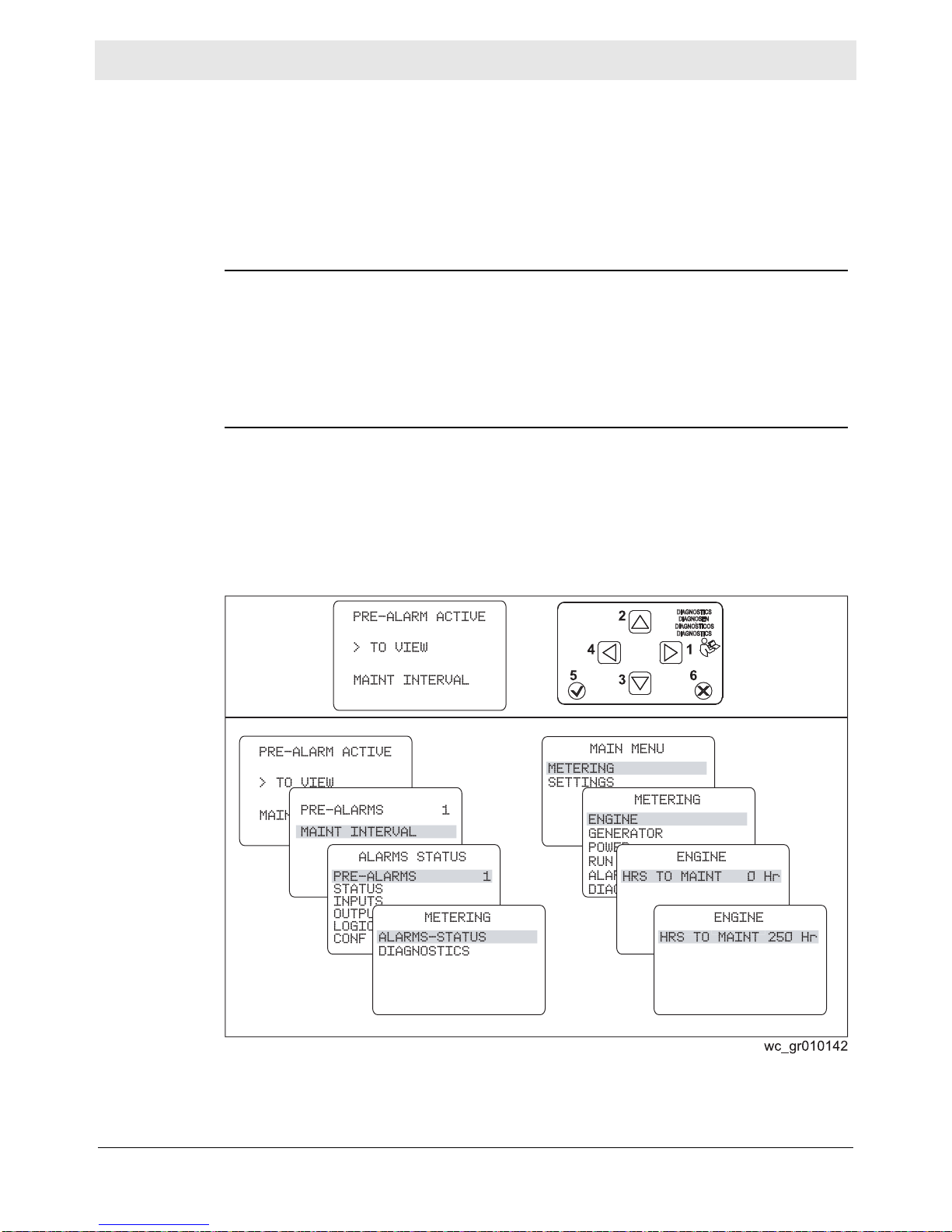
Working with Basler Controller
8.15 Resetting the Maintenance Interval Pre-Alarm
Mobile Generator
Requirements
Background
Procedure
Machine stopped
Start switch in REMOTE START
Note: Internal programming of the genset controller, or closed connections to a
remote start switch, may cause the machine to start unexpectedly. Be prepared for
the engine to start even with the engine start switch in the REMOTE START
position.
When the MAINT INTERVAL pre-alarm is active, the PRE-ALARM ACTIVE screen
is displayed and the red LED flashes.
The maintenance interval pre-alarm may be reset by using either of two different
methods: 1) by holding the “X” reset button while the MAINT INTERVAL pre-alarm
screen is being displayed, or 2) through the METERING menu. Both methods are
described below.
Perform the procedure below to reset the maintenance interval pre-alarm.
1. With the PRE-ALARM ACTIVE screen showing, press and hold the “X” reset
button (6) for 10–20 seconds. This will clear the pre-alarm and reset the
maintenance interval timer back to 250 (or the value it is currently set to).
If that method is unsuccessful, continue.
2. Press the right arrow button (1) to access the PRE-ALARMS menu.
This procedure continues on the next page.
90
wc_tx003229gb_FM10.fm
Page 91

Mobile Generator Working with Basler Controller
Continued from the previous page.
3. With the PRE-ALARMS screen showing (MAINT INTERVAL highlighted), press
the left arrow button (4) three times.
4. Using the up/down arrow buttons highlight METERING. Then, press the right
arrow button.
5. Using the up/down arrow buttons highlight ENGINE. Then, press the right arrow
button.
6. Highlight HRS TO MAINT. Then, press and hold the “X” reset button for 10–20
seconds. This will clear the pre-alarm and reset the maintenance interval timer
back to 250 (or the value it is currently set to).
7. Exit by repeatedly pressing the left arrow button until the READY screen
appears.
Result
The maintenance interval interval pre-alarm has now been reset.
wc_tx003229gb_FM10.fm
91
Page 92

Working with Basler Controller
8.16 Resetting a Loss of Voltage Pre-Alarm
Mobile Generator
Background
The loss of voltage pre-alarm condition occurs most often because of an open lug
door switch. During a loss of voltage pre-alarm, the LCD will display the screens
below.
To reset the loss of voltage pre-alarm, simply close the lug door . If the volt age does
not return to normal, further troubleshooting will be needed.
Note: The loss of voltage pre-alarm will only occur when the voltage selector
switch is in the 120/240 position. The condition will still exist if in a 3-phase mode,
but the pre-alarm will not activate.
92
wc_tx003229gb_FM10.fm
Page 93

Mobile Generator Working with Basler Controller
8.17 Accessing and Using the Event Log
Requirements
Background
Procedure
Machine stopped
Start switch in REMOTE START
Note: Internal programming of the genset controller, or closed connections to a
remote start switch, may cause the machine to start unexpectedly. Be prepared for
the engine to start even with the engine start switch in the REMOTE START
position.
The event log allows the technician to review recent events of the machine
including pre-alarm and alarm (shut-down) conditions. The event log can aid the
technician in diagnosing machine problems.
Note: Before accessing the event log, check the date and time of the genset
controller. The date and times listed in the event log will be relative to the date an d
time setting of the genset controller.
Perform the procedure below to access the event log.
1. At the READY screen, press the right arrow button to bring up the MAIN menu.
2. Highlight METERING. Then, press the right arrow button.
3. Highlight ALARMS-STATUS. Then, press the right arrow button.
4. Highlight EVENT LOG. Then, press the right arrow button.
The LCD displays the events of the event log. Events with the suffix “A” are alarm
conditions. Events with the suffix “P” are pre-alarm conditions. The events are:
LCD Screen Meaning
OVERCRANK A Overcrank pre-alarm
ENGINE RUNNING Engine running
PROT SHUTDOWN Protec tive shutdown
EMERGENCY STOP A Emergency stop alarm
ATS INPUT CLOSED Automatic transfer switch input closed
NORM SHUTDOWN Normal shutdown
FUEL LEVL SENDR FAIL P Fuel level sender failure pre-alarm
FUEL LEVL SENDR FAIL A Fuel level sender failure alarm
LOW FUEL LEVEL P Low fuel level pre-alarm
LOW FUEL LEVEL A Low fuel level alarm
OVER VOLTAGE P Over voltage pre-alarm
OVER CURRENT P Over current pre-alarm
LOW OIL PRES A Low oil pressure alarm
LOSS OF VOLT P Loss of voltage pre-alarm
LOSS OF VOLT Loss of voltage
LOW OIL PRES P Low oil pressure pre-alarm
LOW BATT VOLT P Low battery voltage pre-alarm
OIL SNDR FAIL P Oil sender failure pre-alarm
OIL SNDR FAIL Oil sender failure
wc_tx003229gb_FM10.fm
93
Page 94

Working with Basler Controller
LCD Screen Meaning
GEN TEST LOADED Generator test loaded
MAINT INTERVAL P Maintenance interval pre-alarm
LOW COOL LEVEL A Low coolant level alarm
5. Highlight the event of interest. Then, press the right arrow button.
Details of the event appear: They are:
ACTIVE
OCCURENCE COUNT
FIRST DATE
FIRST TIME
LAST DATE
LAST TIME
FIRST ENG HRS
LAST ENG HRS
DETAILS
Mobile Generator
Most recent
event
To find the alarm event that has occurred most recently:
1. Scroll to each alarm event and record the time it occurred.
2. Compare the dates and times of all alarm e vents. Th e one with the most current
date and time is the most recent.
94
wc_tx003229gb_FM10.fm
Page 95

Mobile Generator
AUS
APAGADO
ARRET
OFF
START / LAUFEN
ARRANQUE / MARCHA
DEMARRER / MARCHE
START / RUN
E
M
E
R
G
E
N
C
Y
S
T
O
P
AUS
APAGADO
ARRET
OFF
START / LAUFEN
ARRANQUE / MARCHA
DEMARRER / MARCHE
START / RUN
9 Operation (Deep Sea Controller)
9.1 Main Circuit Breaker
Operation (Deep Sea Controller)
Location
Various styles of main circuit breakers may be found on Wacker Neuson Mobile
generators. The main circuit breaker (a) is located on the control panel.
Note: Graphic is representative only. Your machine may vary.
a
START / RUN
START / LAUFEN
ARRANQUE / MARCHA
DEMARRER / MARCHE
OFF
AUS
APAGADO
START / RUN
START / LAUFEN
ARRANQUE / MARCHA
DEMARRER / MARCHE
OFF
AUS
APAGADO
ARRET
ARRET
Functions
wc_gr011444
■ The main circuit breaker interrupts power from the volt age se lector switch to the
terminal lugs.
■ The main circuit breaker does not interrupt power to the convenience
receptacles.
WARNING
Electric shock hazard. High voltage is present inside the control panel while the
engine is running.
► Do not open the control panel unless the engine is stopped.
NOTICE: Before shutting down the generator or performing any service to the
generator, make sure the main circuit breaker is in the OFF position.
wc_tx003580gb_FM10.fm
95
Page 96

Operation (Deep Sea Controller)
OFFOFF
ONON
a
wc_gr011478
9.2 Genset Controller Power Switch
Mobile Generator
Description
Function
The genset controller power switch (a) is a two-position switch: ON and OFF.
Position Function LCD Screen
ON When set to this position:
■ Power is supp lie d to th e genset
controller.
■ The genset controller boots up and sets
itself to the Stop/Reset mode—the
engine is ready to be started.
“Generator at Rest” followed
by the status screens that
scroll.
OFF When set to this position, power to the
genset controller is disconnected.
Blank screen (off)
96
wc_tx003580gb_FM10.fm
Page 97

Mobile Generator
wc_gr011503
277/480V
120/240V
1Ø3Ø
3Ø
1Ø
DIESELDIESEL
SOLAMENTE COMBUSTIBLE DE BAJO CONTENIDO DE AZUFREO COMBUSTIBLE DE SOLAMENTE COMBUSTIBLE DE BAJO CONTENIDO DE AZUFREO COMBUSTIBLE DE
ULTRABAJO CONTENIDO DE AZUFRE.ULTRABAJO CONTENIDO DE AZUFRE.
NUR NIEDRIGEN SCHWEFELKRAFTSTOFF ODER ULTRANIEDRIGEN SCHWEFELKRAFTSTOFF.NUR NIEDRIGEN SCHWEFELKRAFTSTOFF ODER ULTRANIEDRIGEN SCHWEFELKRAFTSTOFF.
STOPSTOP
PELIGROPELIGRO
GEFAHRGEFAHR
DANGERDANGER
DANGERDANGER
177416177416
!!
!!
1Ø
120/240V
208/240V 3
Ø
3Ø
277/480V
3Ø
346/600V
120/139V 1
Ø
a
b
9.3 Selecting the Voltage
Operation (Deep Sea Controller)
Location
Selecting the
voltage
One of two types of voltage selector switch—either three-position (a) or fourposition (b)—is mounted to the machine near the lugs.
WARNING
Electric shock hazard. High voltage is present inside the voltage selector switch
enclosure when the engine is running.
► Do not open the voltage selector switch enclosure unless the engine is stopped.
The chart below lists the ranges of voltages available in each of the switch
positions. Select the desired voltage by rotating the handle of the voltage selector
switch. Then, use the voltage adjustment rheostat to set the exact voltage you
require. The voltage is displayed on the LCD panel.
Range of Voltages Available
Switch position
3Ø at lugs
(L–L–L)
1Ø at lugs
(L–N)
1Ø at lugs
(L-L)
1Ø at twist lock
L-N (120V) L-L (240V)
1Ø at GFCI
120/240 VAC 1Ø — 110–125 220–250 110–125 220–250 110–125
208/240 VAC 3Ø
190–240 110–139 190–240 110–139 190–240 110–139
120/139 VAC 1Ø
277/480 VAC 3Ø 380–480 220–277
346/600 VAC 3Ø
1
540–600 — — — — —
1
Not available on all models.
2
Not available on 600V models.
2
190–240
2
110–139
2
190–240
2
110–139
NOTICE: Do not change the position of the voltage selector switch while the
engine is running. Doing so can cause arcing which can damage the voltage
selector switch and the generator windings.
2
wc_tx003580gb_FM10.fm
97
Page 98

Operation (Deep Sea Controller)
AUSAUS
APAGADOAPAGADO
ARRETARRET
OFFOFF
REMOTE STARTREMOTE START
FERNSTARTFERNSTART
ARRANQUE REMOTOARRANQUE REMOTO
DEMARRAGE A DEMARRAGE A
DISTANCEDISTANCE
START / LAUFENSTART / LAUFEN
ARRANQUE / MARCHAARRANQUE / MARCHA
DEMARRER / MARCHEDEMARRER / MARCHE
START / RUNSTART / RUN
E
M
E
R
G
E
N
C
Y
S
T
O
P
A
Ø
HZ
V
R
Basler
DIAGNOSTICS
DIAGNOSEN
DIAGNOSTICOS
DIAGNOSTICS
042563
wc_gr011502
c
A
Ø
HZ
V
R
Basler
DIAGNOSTICS
DIAGNOSEN
DIAGNOSTICOS
DIAGNOSTICS
AUSAUS
APAGADOAPAGADO
ARRETARRET
OFFOFF
REMOTE STARTREMOTE START
FERNSTARTFERNSTART
ARRANQUE REMOTOARRANQUE REMOTO
DEMARRAGE A DEMARRAGE A
DISTANCEDISTANCE
START / LAUFENSTART / LAUFEN
ARRANQUE / MARCHAARRANQUE / MARCHA
DEMARRER / MARCHEDEMARRER / MARCHE
START / RUNSTART / RUN
Mobile Generator
Using the
rheostat
The voltage adjustment rheostat (c) is used to fine-tune the voltage as needed
while the machine is running.
Care must be taken when using the voltage adjustment rhe ostat because adjusting
the voltage for 3-phase operation affects the voltage available at the single-phase
outlets. As the 3-phase voltage increases, so does the single-phase voltage.
NOTICE: Do not use the GFCI or twist-lock receptacle (120V) when the 1Ø vo ltage
is above 135V. Damage to the receptacle and the tools connected to it may occur.
Switch Position
208 VAC 3Ø
120 VAC 1Ø
3Ø Voltage
(L-L-L)
208 208 120 120
220 220 125 125
240 240
277/480 VAC 3Ø 480 240 139
460 230 133
346/600 VAC 3Ø
3
600
540
Corresponding 1Ø voltage
Twist lock receptacle
L-L (240V) L-N (120V) 120V GFCI
139
1
1
2
139
139
133
1
1
2
1
Do not use receptacle with this voltage.
2
Voltage may be too high for some tools and equipment. Check tool/equipment specifications.
3
Not available on all models.
wc_tx003580gb_FM10.fm
98
Page 99

Mobile Generator
AUTAUTOO
DEEP SEA ELECTRONICDEEP SEA ELECTRONICSS
DSE 731DSE 73100
DSE
OpenOpen
CloseClose
Gen-SetGen-Set
OpenOpen
CloseClose
LoadLoad
AlarmAlarm
Warningarning
Main Breaker OpenMain Breaker Open
Low SpeedLow Speed ActiveActive
StartStartLampLamp Testest
Horn ResetHorn Reset
AutoAuto
ModeMode
ManualManual
ModeMode
Stop/ResetStop/Reset
12 13 14 15 16 17
9
11
8
7
6
2
1
3
10
4
5
wc_gr011485
Operation (Deep Sea Controller)
9.4 Deep Sea Controller Buttons/Functions
Ref. Button/function
1 Right arrow button (right / forward)
2 Up arrow button
3 Down arrow button
4 Left arrow button (left / backward)
5 Check mar k but to n (e nt er / acce pt)
This button is used when navigating through the genset controller menus.
Press this button to accept a new value or menu item.
6 Alarm indicator
Illuminates during a fault condition that has stopped the engine.
7 Warning indicator
Illuminates during a non-critical alarm condition. Note: non critical alarm
conditions may lead to shut-down conditions.
8 Main breaker open indicator
Illuminates whenever the main circuit breaker is open.
9 Low speed active indicator
Illuminates when the engine idle speed is set to low idle (if equipped).
10 Load button (not used)
11 Gen-Set button (not used)
wc_tx003580gb_FM10.fm
99
Page 100

Operation (Deep Sea Controller)
Ref. Button/function
12 Stop / Reset
Pressing this button:
■ Sets the genset controller into its Stop/Reset mode
■ Clears any alarm conditions for which the triggering criteria have been
rectified.
13 Manual mode
Pressing this button:
■ Sets the genset controller to the Manual mode
In Manual mode, the generator can be started and operated.
14 (not used)
15 Auto mode
Pressing this button:
■ Sets the genset controller to the Auto mode
In Auto mode, the generator can only be started and operated by a remote
switch.
16 Lamp test / horn reset
Pressing this button:
■ Silences the audible alarm
■ Illuminates all of the LEDs as a lamp test feature (push and hold to perform
test)
17 Start
Pressing this button:
■ Starts the engine
This button is only active in Manual mode.
Mobile Generator
100
wc_tx003580gb_FM10.fm
 Loading...