

Page 1

Operator’s Manual
Notice d’Emploi
Roller
Rouleau
RD 7
5000185489 17 0911
5000185489
Page 2

Copyright
notice
© Copyright 2011 by Wacker Neuson Production Americas LLC
All rights, including copying and distribution rights, are reserved.
This publication may be photocopied by the original purchaser of the machine. Any
other type of reproduction is prohibited without express written permission from
Wacker Neuson Production Americas LLC.
Any type of reproduction or distribution not authorized by Wacker Neuson Production
Americas LLC represents an infringement of valid copyrights. Violators will be
prosecuted.
Trademarks
Manufacturer
Original
instructions
All trademarks referenced in this manual are the property of their respective owners.
Wacker Neuson Production Americas LLC
N92W15000 Anthony Avenue
Menomonee Falls, WI 53051 U.S.A.
Tel: (262) 255-0500 · Fax: (262) 255-0550 · Tel: (800) 770-0957
www.wackerneuson.com
This Operator’s Manual presents the original instructions. The original language of this
Operator’s Manual is American English.
5000185465 17 0911
Page 3

RD 7 Foreword
Foreword
Machines
covered in
this manual
Machine Item Number
RD 7H 0008042
RD 7H-ES 0009408, 0620794
RD 7H-S 0009487, 0620795
RD 7-RAW 0620079, 0620478, 0620596
Machine
documentation
Expectations
for
information in
this manual
From this point forward in this documentation, Wacker Neuson Production
Americas LLC will be referred to as Wacker Neuson.
Keep a copy of the Operator’s Manual with the machine at all times.
Use the separate Parts Book supplied with the machine to order replacement
parts.
Refer to the separate Repair Manual for detailed instructions on servicing and
repairing the machine.
If you are missing any of these documents, please contact Wacker Neuson to
order a replacement or visit www.wackerneuson.com.
When ordering parts or requesting service information, be prepared to provide
the machine model number, item number, revision number, and serial number.
This manual provides information and procedures to safely operate and
maintain the above Wacker Neuson model(s). For your own safety and to
reduce the risk of injury, carefully read, understand, and observe all instructions
described in this manual.
Wacker Neuson expressly reserves the right to make technical modifications,
even without notice, which improve the performance or safety standards of its
machines.
The information contained in this manual is based on machines manufactured
up until the time of publication. Wacker Neuson reserves the right to change
any portion of this information without notice.
CALIFORNIA
Proposition
65 Warning
Laws
pertaining to
spark
arresters
Engine exhaust, some of its constituents, and certain vehicle components, contain
or emit chemicals known to the State of California to cause cancer and birth
defects or other reproductive harm.
NOTICE: State Health Safety Codes and Public Resources Codes specify that in
certain locations spark arresters be used on internal combustion engines that use
hydrocarbon fuels. A spark arrester is a device designed to prevent accidental discharge of sparks or flames from the engine exhaust. Spark arresters are qualified
and rated by the United States Forest Service for this purpose. In order to comply
with local laws regarding spark arresters, consult the engine distributor or the local
Health and Safety Administrator.
wc_tx001345gb.fm 3
Page 4

Foreword RD 7
Manufacturer’s
approval
This manual contains references to approved parts, attachments, and modifications. The following definitions apply:
Approved parts or attachments are those either manufactured or provided by
Wacker Neuson.
Approved modifications are those performed by an authorized Wacker
Neuson service center according to written instructions published by Wacker
Neuson.
Unapproved parts, attachments, and modifications are those that do not
meet the approved criteria.
Unapproved parts, attachments, or modifications may have the following consequences:
Serious injury hazards to the operator and persons in the work area
Permanent damage to the machine which will not be covered under warranty
Contact your Wacker Neuson dealer immediately if you have questions about
approved or unapproved parts, attachments, or modifications.
4 wc_tx001345gb.fm
Page 5

EC Declaration of Conformity
Manufacturer
Wacker Neuson Production Americas LLC, N92W15000 Anthony Avenue,
Menomonee Falls, Wisconsin USA
Product
Product
Product category
Product function
Item number
Net installed power
Measured sound power level
Guaranteed sound power level
RD 7H-ES, RD 7H-S
Vibrating Walk-Behind Rollers
To compact asphalt
0620794, 0620795
5,1 kW
107 dB(A)
108 dB(A)
Conformity Assessment Procedure
According to ANNEX VIII
Notified Body
Lloyds Register Quality Assurance Limited (Notified Body No 0088)
71 Fenchurch Street, London EC3M 4BS, United Kingdom
Guidelines and Standards
We hereby declare that this product meets and complies with the relevant regulations and
requirements of the following guidelines and standards:
2011-CE-RD7H_en.fm
2006/42/EC, 2000/14/EC, 2004/108/EC, EN 500-1, EN 500-4
Authorized Person for Technical Documents
Axel Häret, Wacker Neuson SE, Preußenstraße 41, 80809 München
Menomonee Falls, WI, USA, 22.08.2011
William Lahner
Vice President of Engineering
Paul Sina
Manager, Product Engineering
Original Declaration of Conformity
Page 6

Page 7

Table of ContentsRD 7
Foreword 3
EC Declaration of Conformity 5
1 Safety Information 9
1.1 Signal Words Used in this Manual ....................................................... 9
1.2 Machine Description and Intended use .............................................. 10
1.3 Operating Safety ................................................................................ 11
1.4 Operator Safety While Using Internal Combustion Engines ............... 13
1.5 Service Safety .................................................................................... 14
2 Labels 16
2.1 Label Locations .................................................................................. 16
2.2 Safety and Informational Labels ......................................................... 17
3 Lifting and Transporting 22
4 Operation 23
4.1 Preparing the Machine for First Use ................................................... 23
4.2 Controls and Service Locations .......................................................... 24
4.3 Position of the Operator ..................................................................... 25
4.4 Refueling the Machine ........................................................................ 26
4.5 Before Starting ................................................................................... 27
4.6 Engine Throttle Control ...................................................................... 27
4.7 Starting the Machine (RD 7H, RD 7H-S) ............................................ 28
4.8 Starting the Machine (RD 7H-ES) ...................................................... 29
4.9 Cold Weather Starting (RD 7H, RD 7H-S) ......................................... 30
4.10 Engine Speed ..................................................................................... 31
4.11 Stopping the Machine ......................................................................... 31
4.12 Direction and Speed Control .............................................................. 32
4.13 Exciter ................................................................................................ 32
4.14 Back-Up Stop Pad .............................................................................. 33
4.15 Engine Crank ...................................................................................... 33
4.16 Parking Brake ..................................................................................... 34
4.17 Watering System ................................................................................ 34
4.18 Machine Stability ................................................................................ 35
4.19 Operation on Slopes ........................................................................... 36
4.20 Rollovers ............................................................................................ 36
4.21 Emergency Shutdown Procedure ....................................................... 37
wc_bo5000185465_17TOC.fm 7
Page 8

Table of Contents RD 7
5 Maintenance 38
5.1 Maintenance Schedule ........................................................................38
5.2 Safety-Related Spare Parts .................................................................39
5.3 Checking Engine Oil ............................................................................41
5.4 Changing Engine Oil and Oil Filter ......................................................42
5.5 Fuel System ........................................................................................43
5.6 Engine Air Filter ...................................................................................45
5.7 Checking and Adjusting Valve Clearances .........................................46
5.8 Engine Cooling System .......................................................................47
5.9 Mechanical Oil Pressure Monitoring ....................................................48
5.10 Scraper Bars .......................................................................................49
5.11 Water Spray Bars ................................................................................50
5.12 Hydraulic Oil Requirements .................................................................51
5.13 Hydraulic Oil Level ..............................................................................52
5.14 Changing Hydraulic Fluid and Filter ....................................................53
5.15 Direction Lever Adjustment .................................................................54
5.16 Pressure Washing the Machine ..........................................................56
5.17 Storing the Machine ............................................................................56
6 Troubleshooting 57
7 Technical Data 58
7.1 Engine .................................................................................................58
7.2 Roller ...................................................................................................59
7.3 Lubrication ...........................................................................................59
7.4 Sound and Vibration Measurements ...................................................60
8 AEM Safety Manual 61
9 Schematics 88
9.1 Hydraulic Schematic ............................................................................88
9.2 Hydraulic Schematic Components ......................................................89
9.3 Hydraulic Diagram ...............................................................................90
9.4 Hydraulic Diagram Components .........................................................91
9.5 RD 7H ES—Electrical Schematic ........................................................92
9.6 RD 7H-ES—Electrical Schematic Components ..................................93
8 wc_bo5000185465_17TOC.fm
Page 9

RD 7 Safety Information
1 Safety Information
1.1 Signal Words Used in this Manual
This manual contains DANGER, WARNING, CAUTION, NOTICE, and
NOTE signal words which must be followed to reduce the possibility
of personal injury, damage to the equipment, or improper service.
This is the safety alert symbol. It is used to alert you to potential personal hazards.
f Obey all safety messages that follow this symbol.
DANGER
DANGER indicates a hazardous situation which, if not avoided, will result in death
or serious injury.
f
To avoid death or serious injury from this type of hazard, obey all safety messages that
follow this signal word.
WARNING
WARNING indicates a hazardous situation which, if not avoided, could result in
death or serious injury.
To avoid possible death or serious injury from this type of hazard, obey all safety mes-
f
sages that follow this signal word.
CAUTION!
CAUTION indicates a hazardous situation which, if not avoided, could result in
minor or moderate injury.
f
To avoid possible minor or moderate injury from this type of hazard, obey all safety messages that follow this signal word.
NOTICE: Used without the safety alert symbol, NOTICE indicates a
situation which, if not avoided, could result in property damage.
Note: A Note contains additional information important to a procedure.
wc_si000115gb.fm 9
Page 10

Safety Information RD 7
1.2 Machine Description and Intended use
This machine is a dual drum vibratory walk-behind roller. The Wacker
Neuson Walk-Behind Roller consists of an upper frame to which are
mounted a diesel engine, a hydraulic tank, a water tank, and a
hydrostatic drive system, and a lower frame which supports two steel
drums, an exciter assembly, and a handle. The engine powers the
hydraulics that provide machine movement and drum vibration. The
vibrating drums smooth and compact the work surface as the
machine moves. The operator uses the handle to control machine
speed and direction.
This machine is intended to be used for compacting sand, gravel, soil,
and asphalt on roadways, walkways, bridges, and parking lots.
This machine has been designed and built strictly for the intended use
described above. Using the machine for any other purpose could
permanently damage the machine or seriously injure the operator or
other persons in the area. Machine damage caused by misuse is not
covered under warranty.
The following are some examples of misuse:
• Using the machine as a ladder, support, or work surface
• Using the machine to carry or transport passengers or equipment
• Using the machine to tow other machines
• Using the machine to spray liquids other than water (i.e., diesel fuel
on asphalt)
• Operating the machine outside of factory specifications
• Operating the machine in a manner inconsistent with all warnings
found on the machine and in the Operator’s Manual.
This machine has been designed and built in accordance with the
latest global safety standards. It has been carefully engineered to
eliminate hazards as far as practicable and to increase operator
safety through protective guards and labeling. However, some risks
may remain even after protective measures have been taken. They
are called residual risks. On this machine, they may include exposure
to:
• Heat, noise, exhaust, and carbon monoxide from the engine
• Burns from hot hydraulic fluid
• Fire hazards from improper refueling techniques
• Fuel and its fumes
• Personal injury from improper lifting techniques or operating techniques
10 wc_si000115gb.fm
Page 11

RD 7 Safety Information
To protect yourself and others, make sure you thoroughly read and
understand the safety information presented in this manual before
operating the machine.
1.3 Operating Safety
Familiarity and proper training are required for the safe operation of the
machine. Machines operated improperly or by untrained personnel
can be hazardous. Read the operating instructions contained in this
WARNING
Operator qualifications
manual and the engine manual, and familiarize yourself with the
location and proper use of all controls. Inexperienced operators should
receive instruction from someone familiar with the machine before
being allowed to operate it.
Only trained personnel are permitted to start, operate, and shut down
the machine. They also must meet the following qualifications:
• have received instruction on how to properly use the machine
• are familiar with required safety devices
The machine must not be accessed or operated by:
• children
• people impaired by alcohol or drugs
Contact Wacker Neuson for additional training if necessary.
Personal Protective Equipment (PPE)
Wear the following Personal Protective Equipment (PPE) while
operating this machine:
• Close-fitting work clothes that do not hinder movement
• Safety glasses with side shields
• Hearing protection
• Safety-toed footwear
1.3.1 ALWAYS operate the machine with both of your feet on the ground! DO NOT
stand, sit, or ride on machine while in operation.
1.3.2 Always operate machine with all safety devices and guards in place and in
working order. Do not modify or defeat safety devices. Do not operate machine
if any safety devices or guards are missing or inoperative.
1.3.3 ALWAYS check that all controls are functioning properly immediately after
start-up! DO NOT operate the machine unless all controls operate correctly.
1.3.4 ALWAYS remain aware of changing surface conditions and use extra care
when operating over uneven ground, on hills, or over soft or coarse material.
The machine could shift or slide unexpectedly.
wc_si000115gb.fm 11
Page 12

Safety Information RD 7
1.3.5 ALWAYS use caution when operating near the edges of pits, trenches or
platforms. Check to be sure that the ground surface is stable enough to
support the weight of the machine with the operator and that there is no danger
of the roller sliding, falling, or tipping.
1.3.6 ALWAYS position yourself safely when operating machine in reverse or on
hills. Leave enough space between yourself and the machine so you will not
be placed in a hazardous position should the machine slide or tip.
1.3.7 Make sure that all other persons are at a safe distance from the machine. Stop
the machine if people step into the working area of the machine.
1.3.8 ALWAYS remain aware of moving parts and keep hands, feet, and loose
clothing away from the moving parts of the machine.
1.3.9 ALWAYS remain aware of changing positions and the movement of other
equipment and personnel on the job site.
Do not use a cellphone or send text messages while operating this
machine.
Do not subject the roller to jarring impacts by driving it off curbs or off
the back of a truck or trailer.
1.3.10 NEVER operate the machine with the fuel cap loose or missing.
Do not operate the machine with unapproved accessories or
attachments.
Do not transport the machine while it is running.
1.3.11 Never leave the machine running unattended.
1.3.12 Do not use accessories or attachments that are not recommended by Wacker
Neuson. Damage to equipment and injury to the user may result.
1.3.13 Do not touch the engine or muffler while the engine is on or immediately after
it has been turned off. These areas get hot and may cause burns.
1.3.14 Do not operate a machine in need of service or repair.
1.3.15 ALWAYS do periodic maintenance as recommended in the Operator’s
Manual.
1.3.16 Store the machine properly when it is not being used. The machine should be
stored in a clean, dry location out of the reach of children.
1.3.17 Do not use a cellphone or send text messages while operating this machine.
12 wc_si000115gb.fm
Page 13

RD 7 Safety Information
1.4 Operator Safety While Using Internal Combustion Engines
WARNING
Internal combustion engines present special hazards during operation and fueling. Failure to
follow the warnings and safety standards could result in severe injury or death.
f Read and follow the warning instructions in the engine owner’s manual and the
safety guidelines below.
DANGER
Exhaust gas from the engine contains carbon monoxide, a deadly poison. Exposure to carbon monoxide can kill you in minutes.
f NEVER operate the machine inside an enclosed area, such as a tunnel, unless
adequate ventilation is provided through such items as exhaust fans or hoses.
Operating safety
When running the engine:
• Keep the area around exhaust pipe free of flammable materials.
• Check the fuel lines and the fuel tank for leaks and cracks before
starting the engine. Do not run the machine if fuel leaks are present
or the fuel lines are loose.
When running the engine:
• Do not smoke while operating the machine.
• Do not run the engine near sparks or open flames.
• Do not touch the engine or muffler while the engine is running or
immediately after it has been turned off.
• Do not operate a machine when its fuel cap is loose or missing.
• Do not start the engine if fuel has spilled or a fuel odor is present.
Move the machine away from the spill and wipe the machine dry
before starting.
Refueling safety
When refueling the engine:
• Clean up any spilled fuel immediately.
• Refill the fuel tank in a well-ventilated area.
• Replace the fuel tank cap after refueling.
• Do not smoke.
• Do not refuel a hot or running engine.
• Do not refuel the engine near sparks or open flames.
wc_si000115gb.fm 13
Page 14

Safety Information RD 7
1.5 Service Safety
A poorly maintained machine can become a safety hazard! In order
for the machine to operate safely and properly over a long period of
time, periodic maintenance and occasional repairs are necessary.
WARNING
Personal Protective Equipment (PPE)
Wear the following Personal Protective Equipment (PPE) while
servicing or maintaining this machine:
• Close-fitting work clothes that do not hinder movement
• Safety glasses with side shields
• Hearing protection
• Safety-toed footwear
In addition, before servicing or maintaining the machine:
• Tie back long hair.
• Remove all jewelry (including rings).
1.5.1 ALWAYS check all external fasteners at regular intervals.
1.5.2 Do not modify the machine without the express written approval of the
manufacturer.
1.5.3 Do not attempt to clean or service the machine while it is running. Rotating
parts can cause severe injury.
1.5.4 Do not use gasoline or other types of fuels or flammable solvents to clean
parts, especially in enclosed areas. Fumes from fuels and solvents can
become explosive.
1.5.5 Some service procedures require that the machine’s battery be disconnected.
To reduce the risk of personal injury, read and understand the service
procedures before performing any service to the machine.
1.5.6 ALWAYS make sure slings, chains, hooks, ramps, jacks, and other types of
lifting devices are attached securely and have enough weight-bearing capacity
to lift or hold the machine safely. Always remain aware of the location of other
people in the area when lifting the machine.
1.5.7 ALWAYS turn the engine off before servicing the machine. If the engine has
electric start, disconnect the negative terminal on the battery before servicing
the machine.
1.5.8 Keep the area around the muffler free of debris such as leaves, paper, cartons,
etc. A hot muffler could ignite the debris and start a fire.
1.5.9 Do not tip the machine for cleaning or for any other reason.
1.5.10 DO NOT open hydraulic lines or loosen hydraulic connections while the engine
is running! Hydraulic fluid under pressure can penetrate the skin, cause burns,
blind, or create other potentially dangerous hazards. Set all controls in neutral
and turn engine off before loosening the hydraulic lines.
14 wc_si000115gb.fm
Page 15

RD 7 Safety Information
1.5.11 Fluid leaks from small holes are often practically invisible. DO NOT use your
bare hands to check for leaks. Check for leaks using a piece of cardboard or
wood.
1.5.12 Always make sure hose connections have been reconnected back to the
correct fitting. Failure to do so may result in damage to the machine and/or
injury to person on or near the machine.
1.5.13 All adjustments and repairs MUST be completed before operation. Do not
operate the machine with a known problem or deficiency! All repairs and
adjustments should be completed by a qualified technician.
1.5.14 Before you start the machine, ensure that all tools have been removed from
the machine and that replacement parts and adjusters are firmly tightened.
1.5.15 When replacement parts are required for this machine, use only
Wacker Neuson replacement parts or those parts equivalent to the
original in all types of specifications, such as physical dimensions,
type, strength, and material.
1.5.16 Keep the machine clean and labels legible. Replace all missing and hard-toread labels. Labels provide important operating instructions and warn of
dangers and hazards.
1.5.17 ALWAYS replace safety devices and guards after repairs and maintenance.
wc_si000115gb.fm 15
Page 16
Labels RD 7
2Labels
2.1 Label Locations
O
D
Q
L
V
K
N
L
J
T
C
S
M
A
B, F, U
P
E
G
H
M
SR
16 wc_si000398gb.fm
Page 17
RD 7 Labels
STOP
2.2 Safety and Informational Labels
Wacker Neuson machines use international pictorial labels where
needed. These labels are described below.
Label Meaning
A DANGER!
Asphyxiation hazard.
Engines emit carbon monoxide.
0178715
Do not run the machine indoors or in an
enclosed area unless adequate
ventilation, through such items as
exhaust fans or hoses, is provided.
Read the Operator’s Manual. No
sparks, flames, or burning objects near
the machine. Stop the engine before
refueling.
B WARNING!
Hot surface
C WARNING!
Read and understand the supplied
Operator’s Manual before operating the
machine. Failure to do so increases the
risk of injury to yourself and others.
D WARNING!
To prevent hearing loss, wear hearing
protection when operating the machine.
wc_si000398gb.fm 17
Page 18

Labels RD 7
Label Meaning
E Guaranteed sound power level in
dB(A).
F CAUTION!
Use only clean, filtered diesel fuel.
L O C A L W A C K E R
N G V O N
E L M A N U A L D E O P E R A C I O N D E B E
S E R R E T E N I D O E N L A M A Q U I N A .
C O N T A C T E A S U D I S T R IB U I D O R
W A C K E R M A S C E R C A N O P
P E D I R U N E J E M P L A R
A D I C I O N A L .
L A N O T I C E D ' E M P L O I D O I T
E T R E M U N I E S U R L A M A C H I N E .
C O N T A C T E R L E D I S T R I
W A C K E R L E P L U S P R O C H E
P O U R C O M M A N D E R U N
E X E M P L A I R E S U P P L E M E N T A I R E .
B U T E U R
A R A
machine. A replacement Operator’s
Manual can be ordered through your
1 1 5 0 9 6
local Wacker Neuson distributor.
G Operator’s Manual must be stored on
O P E R A T O R ' S M A N U A L M U S T B E
S T O R E D O N M A C H I N E .
R E P L A C E M E N T O P E R A T O R ' S
M A N U A L C A N B E O R D E R E D
T H R O U G H Y O U R
D I S T R I B U T O R .
D I E B E T R I E B S V O R S C H R I F T M U S S
A N D E R M A S C H I N E A U F B E W A H R T
W E R D E N . Z U R B E S T E L L U
E R S A T Z B Ü C H E R N W E N D E N S IE
S I C H B IT T E A N I H R E N
Ö R T L I C H E N W A C K E R H Ä N D L E R .
H Water control valve.
J Vibration control ON/OFF.
K NOTICE
No lift point.
18 wc_si000398gb.fm
Page 19

RD 7 Labels
Label Meaning
L NOTICE
Lifting point.
M Tie-down point.
N Engine oil drain.
O Hydraulic oil reservoir fill tube.
P Hydraulic oil drain.
Q Key switch, engine start:
Off
On
Start
R This machine may be covered by one
or more patents.
wc_si000398gb.fm 19
Page 20

Labels RD 7
Label Meaning
S A nameplate listing the model number,
item number, revision number, and
serial number is attached to each unit.
Please record the information found on
this nameplate so it will be available
should the nameplate become lost or
damaged. When ordering parts or
requesting service information, you will
always be asked to specify the model
number, item number, revision number,
and serial number of the unit.
T
Check engine oil level.
Use SAE10W30.
Check the fuel level.
Engage parking brake.
Turn vibration off.
Pull engine throttle out.
20 wc_si000398gb.fm
Page 21

RD 7 Labels
Label Meaning
Pull decompression lever up.
Insert crank handle.
Rotate crank handle counterclockwise
5X.
Remove crank handle.
Disengage parking brake.
U Low sulfur fuel or ultra low sulfur fuel
only.
V Parking brake.
wc_si000398gb.fm 21
Page 22

Lifting and Transporting RD 7
3 Lifting and Transporting
WARNING
Crushing and machine damage hazards. Improper lifting techniques can cause the
machine to fall.
f Observe the safety guidelines below when lifting and transporting the machine.
Lifting
• Attach a sling or chain to the lifting eye
shackle. Each lifting device must have capacity of at least 650 Kg
(1430 lbs).
• Only use steel ropes or chains for hoisting. The rope or chain must
have the suitable specified lifting capacity of 650 Kg (1430 lbs). Do
not use improvised ropes or chains.
NOTICE: Never use any other part of the roller to lift the machine, as
severe damage may occur.
• Do not stand under, or get onto, the machine while it is being hoisted
or moved.
(a)
using a suitable hook or
c
Transporting
Before transporting the machine:
• place blocks in front of and behind each drum.
• use the front and rear tie-downs
• place the lift handle
NOTICE: Only use the tie-downs to secure the machine. Do not use
any other part of the roller to tie the machine down as severe damage
to the machine may occur.
trailer.
(c)
to secure the machine to the
(b)
into the upright position.
22 wc_tx001349gb.fm
Page 23

RD 7 Operation
4 Operation
4.1 Preparing the Machine for First Use
Preparing for first use
To prepare your machine for first use:
4.1.1 Make sure all loose packaging materials have been removed from the
machine.
4.1.2 Check the machine and its components for damage. If there is visible
damage, do not operate the machine! Contact your Wacker Neuson
dealer immediately for assistance.
4.1.3 Take inventory of all items included with the machine and verify that
all loose components and fasteners are accounted for.
4.1.4 Attach component parts not already attached.
4.1.5 Add fluids as needed and applicable, including fuel, engine oil, and
battery acid.
4.1.6 Move the machine to its operating location.
wc_tx000294gb.fm 23
Page 24

Operation RD 7
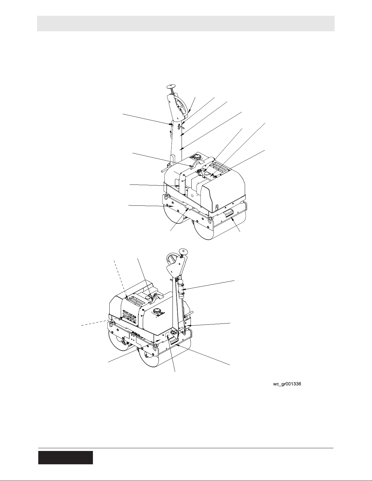
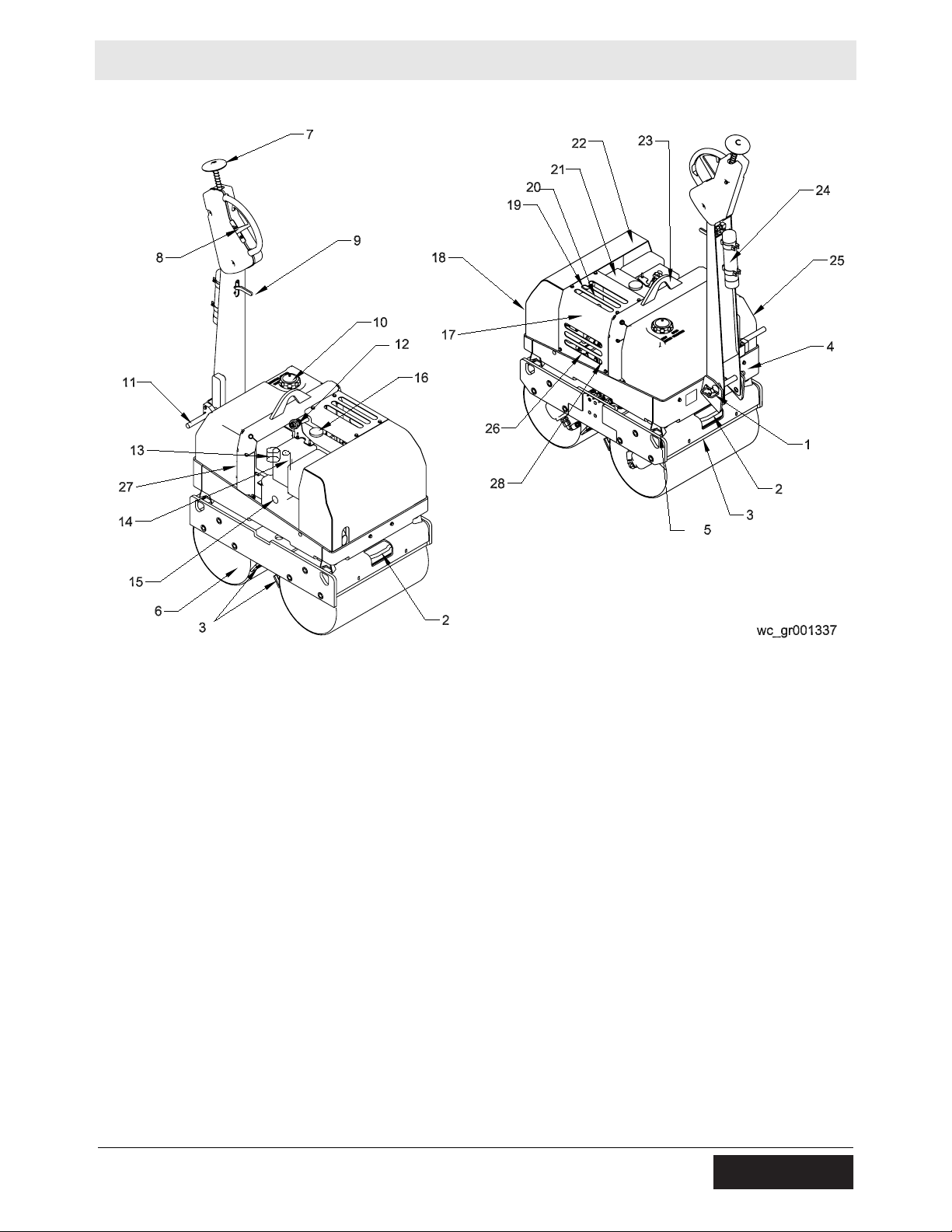
4.2 Controls and Service Locations
Ref. Description Ref. Description
1 Handle locking pin 15 Crank guide sleeve
2 Tie-down location 16 Fuel tank fill cap
3 Scraper bar (4 total) 17 Top cover
4 Water control valve 18 Hydraulic tank (under front cover)
5 Shock mount (4 total) 19 Hydraulic tank fill port (under top cover)
6 Parking brake 20 Hydraulic tank sightglass (through slots)
7 Back-up stop pad 21 Fuel tank
8 Forward/reverse control lever 22 Front cover
9 Exciter control lever 23 Lifting eye
10 Water tank fill cap 24 Operator’s Manual holder
11 Crank storage location 25 Water tank
12 Throttle control 26 Battery
13 Air cleaner indicator 27 Ignition switch
14 Oil dipstick 28 Alarm
24 wc_tx000294gb.fm
Page 25
RD 7 Operation
4.3 Position of the Operator
Safe and efficient use of this machine is the operator’s responsibility.
Full control of the machine is not possible unless the operator
maintains the proper working position at all times.
While operating this machine, the operator must:
• stand or walk behind the machine, facing forward with the handle
directly ahead
• grasp the handle with one hand
• activate the control levers with the other hand
wc_tx000294gb.fm 25
Page 26

Operation RD 7
4.4 Refueling the Machine
Requirements
• Machine shut down
• Engine cool
• Machine/fuel tank level with the ground
• Fresh, clean fuel supply
Procedure
Perform the procedure below to refuel the machine.
WARNING
Fire hazard. Fuel and its vapors are extremely flammable. Burning fuel can cause
severe burns.
f Keep all sources of ignition away from the machine while refueling.
f Do not refuel if the machine is positioned in a truck fitted with a plastic bed liner.
Static electricity can ignite the fuel or fuel vapors.
f Refuel only when the machine is outdoors.
f Clean up spilled fuel immediately.
4.4.1 Remove the fuel cap.
4.4.2 Fill the fuel tank until the fuel level gauge indicates that the tank is full.
CAUTION
Fire and health hazard. Fuel expands when heated. Expanding fuel in an over-filled
tank can lead to spills and leaks.
f Do not overfill the fuel tank.
4.4.3 Reinstall the fuel cap.
Result
The procedure to refuel the machine is now complete.
26 wc_tx000294gb.fm
Page 27
RD 7 Operation
4.5 Before Starting
Before starting the machine, check the following:
• Engine oil level
• Air cleaner maintenance indicator
• Fuel level
• Hydraulic fluid level
• Water tank level
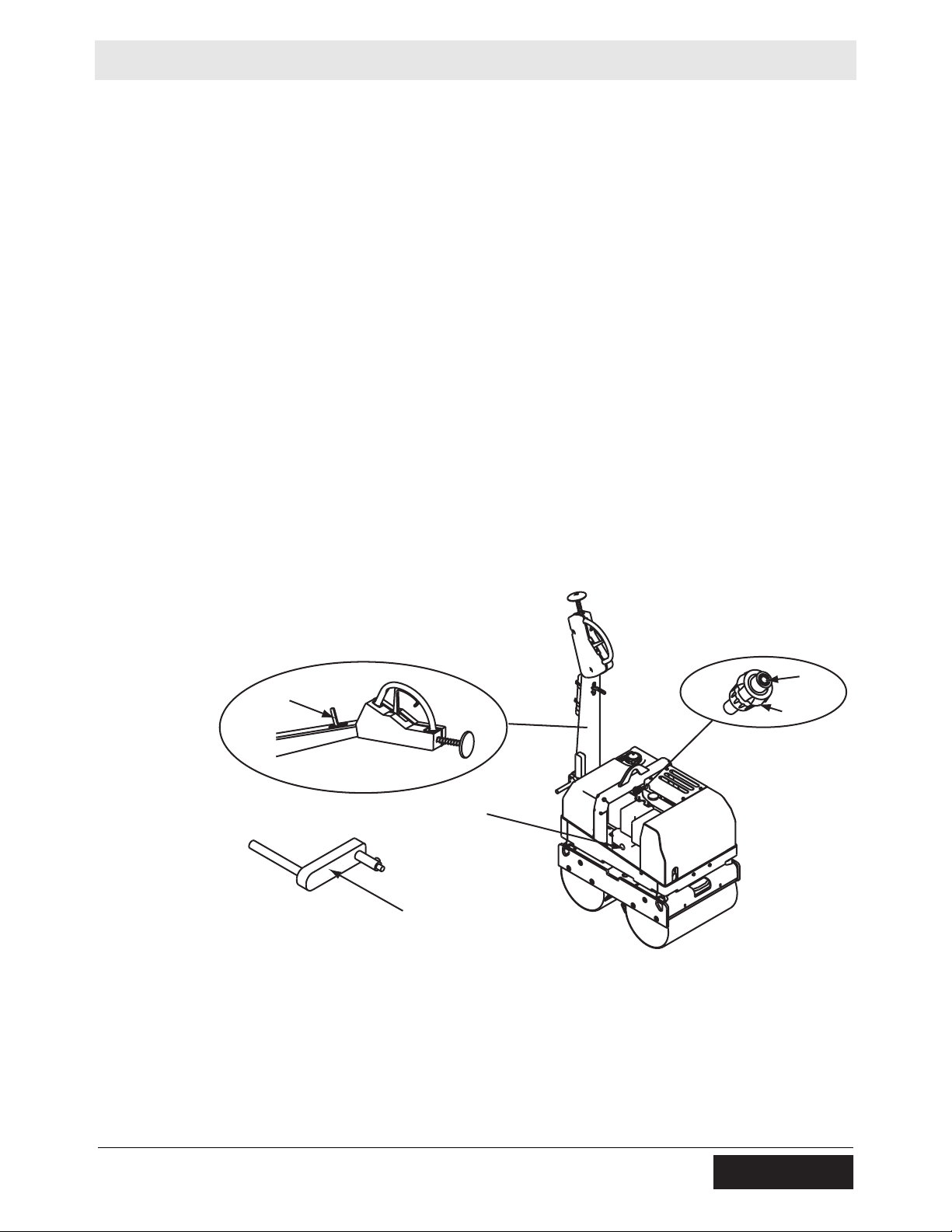
4.6 Engine Throttle Control
See Graphic: wc_gr001338
The engine throttle control (c) is pulled out to start the engine. Press
in on the rubber button (c1) with your thumb while pulling the control
out. The control will stay at any position, and can be fine-tuned by
twisting the control in or out.
To stop the engine, push the throttle control all the way in by pressing
on the rubber button with the heel of your hand.
c1
a
c
b
d
wc_gr001338
wc_tx000294gb.fm 27
Page 28

Operation RD 7
4.7 Starting the Machine (RD 7H, RD 7H-S)
See Graphic: wc_gr001338, wc_gr001339, wc_gr001340
4.7.1 Check that the exciter (a) is in the OFF position.
4.7.2 Pull the throttle control (c) up to open engine throttle.
4.7.3 Turn the decompression lever (f) until stop (f1) is reached. In this
position, the automatic decompression system is heard to engage.
4.7.4 Insert the crank (d) into the guide sleeve (b).
4.7.5 Turn the crank 5 turns to build up pressure for the engine to fire.
4.7.6 Stand alongside the engine, facing the back of the machine (e) and
grasp the tubular grip with both hands.
Do not stand in any other position! Injury may result if the engine
should backfire!
WARNING
4.7.7 Turn the handle slowly until the pawl engages the rachet, then
increase the turning force to build up speed.
Note: The highest speed must be reached when the decompression
lever (f) returns to the (f0) position.
4.7.8 As soon as the engine has started, pull the starting handle out of the
guide sleeve.
You must hold the tubular grip firmly to maintain contact all the time
between the starting handle and the engine. Maintain turning force
WARNING
during the entire hand starting operation.
Note: If backfiring occurs when starting the engine because the crank
handle was not turned firmly enough, the brief reverse rotation at the
handle tube separates the link between the crank lug and the driving
dog.
4.7.9 If the engine begins to run backwards after backfiring (smoke emerges
from air cleaner), release the crank handle immediately and stop the
engine.
4.7.10 To restart the engine, wait until it has come to a standstill, then repeat
the starting procedures.
4.7.11 Allow engine to warm up for a few minutes before operating machine.
e
f1
wc_gr001339
g
f
f0
wc_gr001340
28 wc_tx000294gb.fm
Page 29
RD 7 Operation
4.8 Starting the Machine (RD 7H-ES)
See Graphic: wc_gr001529
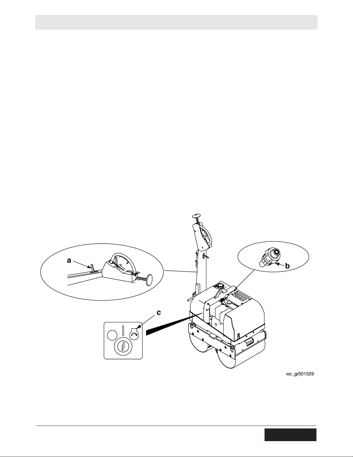
4.8.1 Check that the exciter (a) is in the OFF position.
4.8.2 Pull the throttle control (b) up to open the engine throttle.
4.8.3 Turn the ignition switch (c) to start the engine.
.
When the key is in the ON position, an alarm will sound. The alarm is
a reminder to turn the key to the OFF position when the machine is not
CAUTION
WARNING
4.8.4 Allow the engine to warm up for a few minutes before operating the
in use. Failure to do this will result in a dead battery.
Note: The alarm will stop when proper oil pressure is reached.
Do not crank the engine starter for more than 15 seconds at one time.
Longer cranking cycles could lead to starter damage.
machine.
wc_tx000294gb.fm 29
Page 30
Operation RD 7
4.9 Cold Weather Starting (RD 7H, RD 7H-S)
See Graphic: wc_gr001338, wc_gr001339, wc_gr001340
At temperatures below approximately -5°C (30°F), always turn the
engine over to ensure that it rotates freely.
4.9.1 Check that the exciter switch (a) is in the OFF position.
4.9.2 Pull the throttle control (c) up to open the engine throttle.
4.9.3 Move the decompression lever (f) to a position that is approximately
halfway between f0 and f1.
4.9.4 Insert the crank (d) into the guide sleeve (b).
4.9.5 Turn the crank 10 turns (rotations) to build up pressure for the engine
to fire.
4.9.6 Clean around the cover of the metering device (g), then:
• remove the cover
• fill with lubricating oil until the level reaches the upper rim
• press the cover on firmly.
4.9.7 Start the engine as normal. See section Starting the Machine.
a
b
d
wc_gr001338
e
f1
g
c1
c
wc_gr001339
f
f0
wc_gr001340
30 wc_tx000294gb.fm
Page 31

RD 7 Operation
4.10 Engine Speed
During operation, run the engine at full throttle. This ensures maximum
exciter speed and will produce the best compaction.
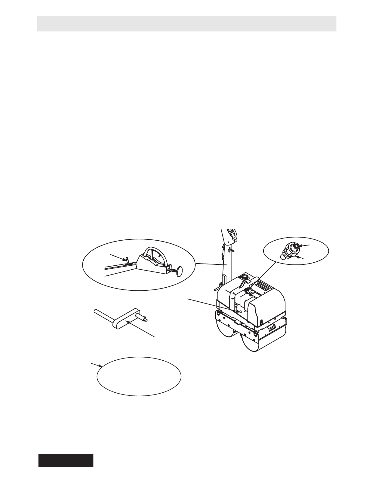
4.11 Stopping the Machine
See Graphic: wc_gr001529
4.11.1 Place the exciter switch (a) in the OFF position.
4.11.2 Close the water control valve.
4.11.3 Push the throttle control (b) to the minimum position to stop the engine.
4.11.4 On electric start machines, turn the engine switch (c) to the OFF
position.
4.11.5 Apply the parking brake.
4.11.6 Clean the scraper bars before storing the machine.
NOTICE: Should the engine ever speed out of control and not stop by
using the throttle control, pulling up on the decompression lever, which
could be hot to the touch, will stop the engine.
wc_tx000294gb.fm 31
Page 32

Operation RD 7
4.12 Direction and Speed Control
See Graphic: wc_gr001341
Travel direction and speed are controlled by the movable lever (a)
inside the handle. From the neutral position, the handle is pushed
away from the operator to travel forward, and towards the operator to
travel in reverse.
Keep both hands on the handle while operating the machine. The
handle may pivot rapidly while in operation and cause injury.
WARNING
Speed is varied by the movement of the lever; the farther the lever is
pushed in either direction, the faster the roller will travel in that
direction.
If the linkage separates from the directional lever while the machine is
running, the roller could “run away” and cause injury. In the event of
WARNING
this occurring, the throttle (b1) must be pushed in to stop the engine.
4.13 Exciter
b1
a
wc_gr001341
The exciter provides the vibration and can be used in most applications
involving cohesive-type soils with heavy clay content, as well as loose
soils and gravel.
NOTICE: DO NOT run the machine over hard surfaces like concrete
or compacted asphalt with the vibration on. Damage to the drum
bearings may result.
32 wc_tx000294gb.fm
Page 33

RD 7 Operation
4.14 Back-Up Stop Pad
See Graphic: wc_gr001342
A back-up stop pad (a) is mounted to the rear section of the machine
behind the control panel. The back-up stop pad operates in reverse
only.
If the machine backs into an obstruction or if the operator becomes
trapped behind it, the pad will be pressed forward and stop the
machine. The machine can move only in the forward direction when
the handle is brought back through the neutral position.
a
STOP
4.15 Engine Crank
See Graphic: wc_gr001345
The engine crank is equipped with kick-back damping to protect the
operator from injury should the engine backfire. The brief reverse
rotation at the handle tube (a) separates the link between the crank lug
(b) and the driving dog (c).
ab
wc_gr001342
c
wc_tx000294gb.fm 33
wc_gr001345
Page 34

Operation RD 7
4.16 Parking Brake
See Graphic: wc_gr001343
The parking brake is used to ensure that the machine will not roll when
not in use. It engages the weld stops on the drum, therefore a small
amount of movement is possible before the brake will catch and stop
the machine.
To disengage the parking brake:
Rotate the handle (a) 90° clockwise and bring it to rest in a shallow
detent.
To engage the parking brake:
Rotate the handle (a) 90° counterclockwise and allow it to rest in the
deep detent.
NOTICE: The parking brake is designed to hold the machine on an
incline with the engine off. Do not drive against the parking brake in the
engaged position. The brake may bend and damage the machine.
a
4.17 Watering System
See Graphic: wc_gr001344
The RD 7 is equipped with a water control valve which allows the roller
to be used wet or dry, and a sprinkler system to distribute the water
evenly across the drums. The water is gravity fed to the sprinklers
when the control valve is in the OPEN (horizontal) position (a).
wc_gr001343
a
wc_gr001344
34 wc_tx000294gb.fm
Page 35

RD 7 Operation
4.18 Machine Stability
WARNING
Crushing hazards. Certain job site conditions or operating practices may adversely
affect machine stability.
f
Follow the instructions below to reduce the risk of tipping or falling incidents.
Surface conditions
Pay attention to changing surface conditions while operating the
machine. Adjust speed and travel direction as necessary to maintain
safe operation.
• Machine stability and traction may be severely reduced when
operating on uneven or rough terrain, rocky soils, or wet or
loosely packed surface material.
• The machine may suddenly tip, sink, or fall when moved onto sur-
faces that have been newly filled with earth.
Travel speed
A fast moving machine is more likely to tip or fall over while making
turns or changing direction.
• Reduce travel speed before turning the machine.
Drum overhang
The machine can tip suddenly if more than half of the drum width
extends beyond the edge of the elevated surface.
• Reduce travel speed and watch the drum position carefully when
operating along the edge of an elevated surface.
• Keep as much of the drum on the elevated surface as possible.
Vibrating on a compacted surface
Activating the vibratory system on a fully compacted surface may
cause the drums to rebound and momentarily lose contact with the
ground. If this occurs while the machine is on an incline, the machine
may slide.
• If the drums rebound on the compacted surface, reduce vibration
speed or stop vibration entirely.
wc_tx000294gb.fm 35
Page 36

Operation RD 7
4.19 Operation on Slopes
See Graphic: wc_gr001346 and wc_gr001347
When operating on slopes or hills, special care must be taken to
reduce the risk of personal injury or damage to the machine. Always
operate the machine up and down hills rather than from side to side.
For safe operation and for protection of the engine, continuous duty
use should be restricted to slopes of 22° (40% grade) or less.
NEVER operate the machine sideways on slopes. The machine may
roll over, even on stable ground.
WARNING
4.20 Rollovers
Proper operation of the machine on slopes will prevent rollovers. Read
and follow Safety instructions in “Operating Safety” and “Operation on
Slopes”. If a machine rollover does occur, care must be taken to
prevent damage to the engine. In this position, oil from the engine
crankcase can flow into the combustion chamber, which can severely
damage the engine next time it is started. If the machine has rolled on
its side, immediate steps should be taken to right the machine.
NOTICE: To prevent damage to the engine after a rollover, the
machine must NOT be started, AND it must be serviced to remove any
oil that may have been trapped in the combustion chambers. Contact
your local Wacker Neuson dealer for instructions or servicing.
22˚
40%
wc_gr001346
wc_gr001347
36 wc_tx000294gb.fm
Page 37

RD 7 Operation
4.21 Emergency Shutdown Procedure
If a breakdown or accident occurs while the machine is operating,
follow the procedure below:
4.21.1 Stop the engine.
4.21.2 Close the fuel valve.
4.21.3 Allow the machine to cool.
4.21.4 Contact the rental yard or machine owner for further instructions.
wc_tx000294gb.fm 37
Page 38

Maintenance RD 7
5 Maintenance
5.1 Maintenance Schedule
The table below lists basic machine maintenance. Tasks designated
with check marks may be performed by the operator. Tasks
designated with square bullet points require special training and
equipment.
Refer to the engine manufacturer’s manual for more information.
Check engine oil level.
Check air cleaner maintenance indicator.
Check the water trap.
Check hydraulic oil level.
Clean the scraper bars.
Check function of back-up stop pad and
direction control lever.
Check tappet clearance.
Examine screw connections.
Replace engine oil and filter.
Check and adjust valve clearances.
Daily
before
starting
3
3
3
3
3
3
After
first
25 hrs.*
Every
250
hrs.
3
Every
500
hrs.
Every
1200
hrs.
Clean cooling system.
Replace fuel filter.
Clean or replace air filter.
Change hydraulic system return line filter.
Check and adjust scraper bars.
**Check linkage components.
Clean battery terminals (RD 7H-ES).
Change hydraulic oil and filter.
*For new or reconditioned engines.
CAUTION: DO NOT tighten cylinder head fastenings.
** Maintain linkages more frequently in dusty environments. Lubricating linkages is not recom-
mended. However, if necessary, use a dry lubricant that does not attract dust.
38 wc_tx000295gb.fm
Page 39

RD 7 Maintenance
5.2 Safety-Related Spare Parts
Overview
This machine is equipped with a back-up stop pad to enhance
operator safety. For your convenience, we have provided the
following diagram and list of replacement parts for this safety-related
feature.
For a complete list of spare parts for this machine, contact your
Wacker Neuson dealer or visit www.wackerneuson.com.
Upper handle diagram
28
16
15
20
145
137
132
77
141
137
132
wc_gr007050
wc_tx000295gb.fm 39
Page 40

Maintenance RD 7
Upper handle parts list
Ref. Part No. Qty. Description
15 0112307 1 Handle
16 0155442 1 Rod
20 0112351 1 Spring
28 0155441 1 Disc
77 0112391 2 Bearing 20 x 20
132 0010367 4 Lock nut M8
137 0010622 10 Flat washer B8,4
141 0011310 2 Hex head screw M8 x 85
145 0011346 2 Hex head screw M8 x 65
Measurement
and Torque
25 Nm / 18 ft.lbs
25 Nm / 18 ft.lbs
40 wc_tx000295gb.fm
Page 41

RD 7 Maintenance
5.3 Checking Engine Oil
See Graphic: wc_gr001348
Engine oil level
Stop the machine, switch off the engine and apply the parking brake.
Check the oil with the machine standing on a level surface.
5.3.1 Clean around the dipstick.
5.3.2 Check the oil level on the extended dipstick (a). If necessary, top up to
the “max” mark.
The engine may be hot enough to cause burns! Allow the engine to
cool prior to servicing.
WARNING
a
wc_gr001348
wc_tx000295gb.fm 41
Page 42

Maintenance RD 7
5.4 Changing Engine Oil and Oil Filter
See Graphic: wc_gr001349
Before changing the oil:
5.4.1 Run the machine to warm the oil.
5.4.2 Park the machine on a flat level surface.
5.4.3 Set all controls in neutral, stop the engine, apply the parking brake, and
allow the engine and fluids to cool.
.
Burn hazard! Avoid contact with the engine oil when draining the
engine. Hot oil can burn!
CAUTION
Note: In the interests of environmental protection, place a plastic sheet
and a container under the machine to collect any liquid that drains off.
Dispose of this liquid in accordance with environmental protection
legislation.
5.4.4 Unscrew the oil drain plug and allow the oil to drain into a 1–1.5 liter
(1–1.5 quarts) container.
5.4.5 Clean the oil drain plug and attach a new seal to it.
5.4.6 Reinstall the drain plug.
5.4.7 Unscrew the filler cap of the oil filter housing. Check the condition of
the O-ring (a) on the filler cap and replace it if it is damaged.
5.4.8 Remove the used filter element. Install a new filter element with the
“TOP” mark facing up.
5.4.9 Add engine oil up to the “MAX” mark on the dipstick; approximately
1.1–1.2 liters (1–1¼ quarts).
5.4.10 Wet the O-ring and threads of the filler plug with high-temperature
grease available from your Hatz Dealer. Then, reinstall the filler plug.
5.4.11 Run the engine for two minutes. Turn off the engine and check the
engine oil level again. Add engine oil as necessary.
5.4.12 Make sure that there is no oil leakage past the filler cap.
a
wc_gr001349
42 wc_tx000295gb.fm
Page 43

RD 7 Maintenance
WARNING
Most used oil contains small amounts of materials that can cause cancer and other
health problems if inhaled, ingested, or left in contact with skin for prolonged periods of time.
f Take steps to avoid inhaling or ingesting used engine oil.
f Wash skin thoroughly after exposure to used engine oil.
5.5 Fuel System
See Graphic: wc_gr001351
Fuel tank water trap
The interval at which you should check the water trap depends upon
the amount of water in the fuel. The normal interval is one week.
Stop the machine, switch off the engine, and apply the parking brake.
5.5.1 Remove the cover from the roller to allow access to the fuel tank water
trap.
5.5.2 Loosen the hex screw (a) until only 2 threads are holding it in place.
5.5.3 Trap the drops of water that emerge in a transparent container.
Note: Since water has a higher specific gravity than diesel fuel, the
water emerges first. The two substances separate at a clearly visible
line.
5.5.4 When only diesel fuel emerges, retighten the hex screw.
NOTICE: Diesel fuel destroys shock mounts. Clean up fuel spillage
immediately.
Changing the fuel filter cartridge
Fuel filter maintenance intervals depend on the purity of the diesel fuel
used. If your fuel is dirty, perform this operation at 250 hours.
Stop the machine, switch off the engine, and apply the parking brake.
Explosion hazard! Diesel fuel is flammable and must be treated with
the necessary caution. Do not smoke near the machine. Avoid sparks
WARNING
and open flames.
5.5.5 Remove the cover from the roller to allow access to the fuel filter.
5.5.6 Place a suitable container under the fuel filter to trap escaping fuel.
5.5.7 Close the fuel supply line.
5.5.8 Pull the fuel supply line (b) off of the fuel filter trap (c) at both sides, and
insert the new filter.
wc_tx000295gb.fm 43
Page 44

Maintenance RD 7
NOTICE: Keep the area clean to prevent dirt from entering the fuel
lines.
5.5.9 Make sure the fuel filter is oriented with the arrow in the direction of fuel
flow.
5.5.10 Open the fuel supply line until fuel begins to flow.
5.5.11 Run the engine briefly to check the fuel filter and lines for leaks.
b
a
c
wc_gr001351
44 wc_tx000295gb.fm
Page 45

RD 7 Maintenance
5.6 Engine Air Filter
See Graphic: wc_gr001352
Checking the air cleaner blockage indicator
5.6.1 Briefly run the engine at full speed. If the rubber bellows is pulled in and
obscures the green zone (a), clean or replace the air filter.
5.6.2 In dusty operating conditions, check the rubber bellows several times
per day.
Cleaning or replacing the engine air filter
The engine may be hot enough to cause burns! Allow the engine to
cool prior to servicing.
WARNING
5.6.3 Loosen the wing nut (b) and remove it. Also remove the air cleaner
cover (c).
Note: The decompression lever will also come off.
5.6.4 Pull out the filter cartridge (e).
5.6.5 Check that the valve plate (f) for the air blockage indicator is clean and
in good condition.
Cleaning dry dirt from the filter cartridge
5.6.6 Blow through the filter cartridge from the inside using a compressed air
gun.
5.6.7 Continue until all dust has been removed.
NOTICE: Only use filtered, dry compressed air. Do not exceed an air
pressure of more than 5 bar (70 psi). Keep the nozzle at a distance of
150 mm (6 in.) from the element.
Cleaning wet or oily dirt from the filter
5.6.8 Change the filter cartridge.
NOTICE: Always trace and correct the cause of wet or oily
contamination of a filter element.
Checking the filter cartridge
5.6.9 Hold the element up to a light or pass a lamp through the middle to
check the condition of the element folds (g).
5.6.10 Check that the sealing surface (d) is in good condition.
NOTICE: If there is even slight damage to the paper filter element or
the sealing surface, replace the filter cartridge.
wc_tx000295gb.fm 45
Page 46

Maintenance RD 7
5.7 Checking and Adjusting Valve Clearances
See Graphic: wc_gr001353
Stop the machine, apply the parking brake and switch off the engine.
5.7.1 Make sure that the compression lever is in position “0”. See section
Starting the Machine.
5.7.2 Remove the cylinder head cover and the gasket.
5.7.3 Turn the engine over in the normal direction of rotation until
compression is felt.
5.7.4 Check the inlet valve clearance between the rocker and the valve stem
using a feeler gauge (a).
5.7.5 If the valve clearance is incorrect, loosen the hex nut (c).
Note: See section Technical Data for valve clearances.
5.7.6 Turn the adjusting screw (b) with a screwdriver until the feeler gauge
(a) can just be pulled through between the rocker and the valve stem
with slight resistance to its movement after the nut (c) has been
retightened.
5.7.7 Repeat this adjustment with the outlet valve.
5.7.8 Place a new gasket under the cylinder head cover, reinstall the
cylinder head cover, and tighten down the screws uniformly.
5.7.9 Run the engine briefly and make sure that the cylinder head cover is
not leaking.
a
b
c
wc_gr001353
d
e
a
b
c
g
f
wc_gr001352
46 wc_tx000295gb.fm
Page 47

RD 7 Maintenance
5.8 Engine Cooling System
See Graphic: wc_gr001354
Stop the machine, apply the parking brake and switch off the engine.
The engine must be allowed to cool down before cleaning.
Dry contamination
5.8.1 Clean all air guide elements and the complete cooling air zones (a) on
the cylinder head and the cylinder and flywheel blades without making
them wet. Blow them dry with compressed air.
Moist or oily contamination
5.8.2 Clean the entire area with a solvent or cold cleaner according to its
manufacturer's instructions, then spray down with a high pressure
water jet. Blow them dry with compressed air.
5.8.3 Trace the source of oil leaks causing greasy dirt. Repair the leaks,
seeking advice of your Hatz dealer if necessary.
5.8.4 After cleaning, run the engine to dry it out and to prevent the formation
of rust.
a
a
a
wc_gr001354
wc_tx000295gb.fm 47
Page 48

Maintenance RD 7
5.9 Mechanical Oil Pressure Monitoring
See Graphic: wc_gr002338
The mechanical oil pressure monitor should be activated:
• when first filling, or after running the fuel tank dry.
• if the engine shut down automatically because the lubricating oil
supply was inadequate.
• after freeing it by turning it at low temperatures.
5.9.1 Add fuel.
5.9.2 Check the engine oil level.
5.9.3 To activate the oil pressure monitor, press the lever (a).
5.9.4 Re-assemble all the parts repositioned or removed. Check that the
capsule elements make a good seal.
Note: Instructions to activate the mechanical oil pressure control are
mentioned on the label (b) placed on the engine.
CAUTION
Even with the mechanical oil pressure control monitoring the oil level,
it must be checked every 8–15 operating hours.
48 wc_tx000295gb.fm
Page 49

RD 7 Maintenance
5.10 Scraper Bars
See Graphic: wc_gr001355
Check the four scraper bars (a) for wear. Replace the scraper bars as
needed.
Cleaning the scraper bars
The scraper bars should be cleaned daily after use or as often as
needed to remove built-up dirt, mud, and tar.
Use a high-pressure water jet and a strong brush if needed.
a
a
a
wc_gr001355
wc_tx000295gb.fm 49
Page 50

Maintenance RD 7
5.11 Water Spray Bars
Background
Clogged or dirty spray bars can prevent water from spraying onto the
drums. If water spray is noticeably reduced or absent even though
there is water in the tank, then clean the spray bars.
Procedure
Follow the procedure below to clean the spray bars.
5.11.1 The spray bars (a) are located behind the drum scrapers.
d
a
c
b
a
a
wc_gr007078
5.11.2 Start the machine. Activate the spray system and check for free flow
of water through each spray hole (b).
5.11.3 If any of the spray holes are blocked, stop the machine and use a
small pointed object (i.e. a stiff piece of wire) to remove the blockage.
5.11.4 Rinse the spray bars with clean water and dry with a soft, clean cloth.
NOTICE: The cap (c) and fitting (d) are not removable.
50 wc_tx000295gb.fm
Page 51

RD 7 Maintenance
5.12 Hydraulic Oil Requirements
Wacker Neuson recommends the use of a premium grade, petroleumbased hydraulic oil with anti-wear and anti-foam characteristics. Good
anti-wear oils contain additives to reduce oxidation, prevent foaming,
and provide for good water separation. These oils offer superior motor
and pump life.
When selecting hydraulic oil for your machine, be sure to specify antiwear properties. Wacker Neuson offers a premium grade hydraulic oil
for use in this machine.
Avoid mixing different brands and grades of hydraulic oils.
Oil Viscosity
Most hydraulic oils are available in different viscosities. The SAE
number for an oil is used strictly to identify viscosity. It does not indicate
the type of oil (engine, hydraulic, gear, etc.). The higher the SAE
number, the thicker the oil.
For normal applications use a good non-detergent, anti-wear,
hydraulic oil with a viscosity rating of SAE 10W30.
wc_tx000295gb.fm 51
Page 52

Maintenance RD 7
5.13 Hydraulic Oil Level
See Graphic: wc_gr001356
A hydraulic oil level sightglass (a) is located on the hydraulic tank and
is visible through the slots on the top cover.
Check the oil level with the machine standing on a level surface. The
oil level should be at the halfway mark on the sightglass. If the level is
low, remove the top cover and top up with hydraulic oil as necessary.
If hydraulic oil continually needs to be added, inspect the hoses and
connections for possible leaks. Repair hydraulic leaks immediately to
prevent damage to the hydraulic components.
a
wc_gr001356
52 wc_tx000295gb.fm
Page 53
RD 7 Maintenance
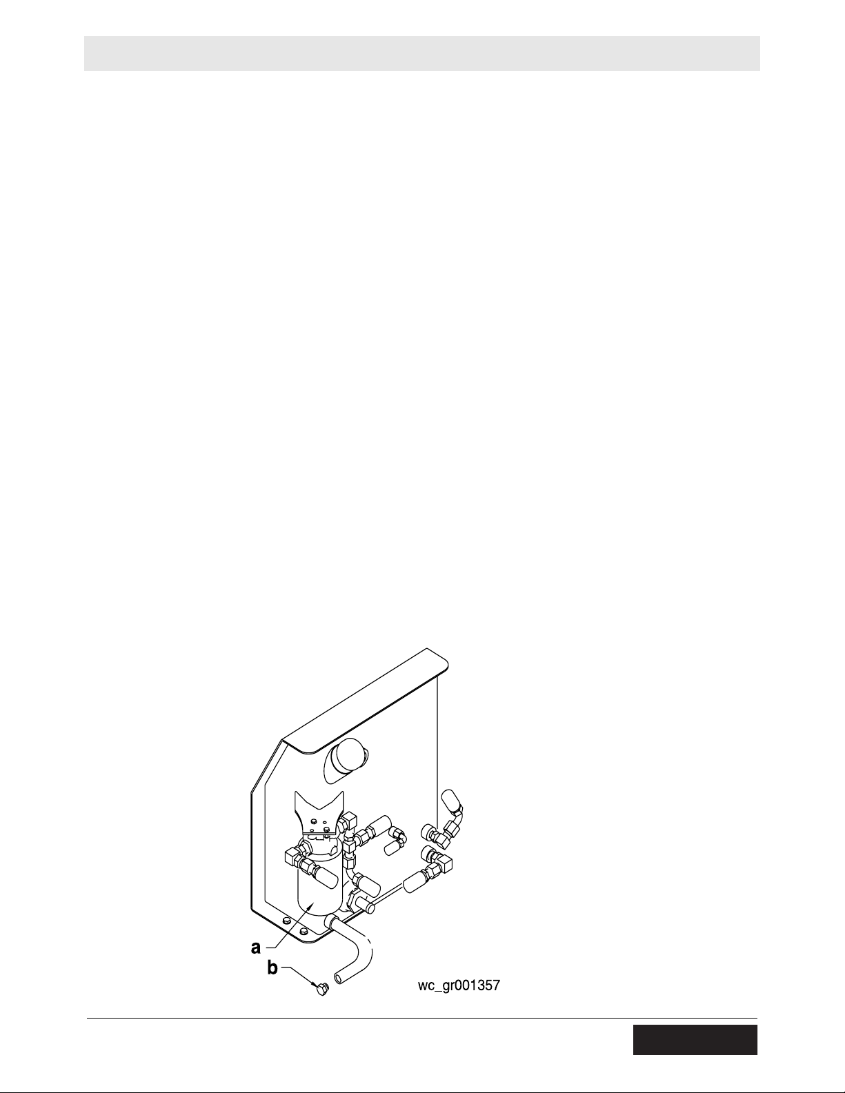
5.14 Changing Hydraulic Fluid and Filter
See Graphic: wc_gr001357
Stop the machine, switch off the engine, and apply the parking brake
with the machine standing on a level surface.
Note: In the interests of environmental protection, place plastic
sheeting and a container under the machine to collect the liquid which
drains off. Dispose of this liquid properly.
5.14.1 Remove the top cover of the roller.
5.14.2 Remove the drain plug (b) from the end of the drain hose that is
attached to the hydraulic tank.
5.14.3 Allow the hydraulic oil to drain into a suitable container.
5.14.4 When all the oil has drained out, reinstall the drain plug back into the
hose and secure it in place.
5.14.5 Place a plastic bag around the filter (a) to contain any oil spillage.
5.14.6 Unscrew the old hydraulic filter.
5.14.7 Install the new hydraulic filter. Screw the new hydraulic filter on by
hand, making sure that it is not cross-threaded.
NOTICE: Use only original spare parts.
5.14.8 Tighten the hydraulic filter using both hands.
5.14.9 Fill the hydraulic tank with hydraulic oil until the level is visible halfway
up the sightglass.
5.14.10 Run the engine briefly, then stop the engine and check for leaks.
5.14.11 Check the oil level in the sightglass, and top up if necessary.
wc_tx000295gb.fm 53
Page 54

Maintenance RD 7
5.15 Direction Lever Adjustment
See Graphic: wc_gr003672
The forward/reverse control lever should have long forward travel and
short reverse travel. If the lever appears out of adjustment, it can be readjusted as follows:
5.15.1 Start the engine. Place the forward/reverse control lever in the
NEUTRAL position (N). Confirm that the machine does not creep. If the
machine does creep, turn the large adjusting nut (4) on the springloaded, cable centering device (5) so that the machine does not creep.
5.15.2 Stop the engine.
5.15.3 Place the forward/reverse control lever in the full FORWARD position
(F). Check the rotation of the drive pump control arm (9). In the full
FORWARD position, the drive pump control arm should rotate, in the
direction shown, as far as possible.
• If the drive pump control arm rotates as far as possible, no further
adjustment is required.
• If the drive pump control arm does not rotate as far as possible,
continue.
5.15.4 Disconnect the clevis (1) from the pivot (2).
5.15.5 Rotate the pivot so that the drive pump control arm rotates as far as
possible. With the forward/reverse control lever in the full FORWARD
position, adjust the clevis and lock nut (8) so that it can hold the drive
pump control arm in the fully rotated position. Reattach the clevis to the
pivot.
Note: If the adjustment cannot be made with the clevis alone, adjust
the linkage (10).
5.15.6 Start the engine and check the NEUTRAL position of the control lever.
• If the machine remains stationary, no further adjustment is
required.
• If the machine creeps forwards or backwards, continue.
5.15.7 Turn off the engine.
5.15.8 Adjust the nut (4) on the spring-loaded, cable centering device as
needed so that the machine remains stationary when the control lever
is in the NEUTRAL position. Start the engine and recheck for machine
creeping/movement. It may take several attempts to find the correct
position. Loosen the nuts (6) holding the cable (3) to the bracket (7)
and reposition the cable if necessary.
5.15.9 The maximum allowable reverse travel speed is 2 km/hr. Do not adjust
the direction control lever so that reverse travel speed is greater than
CAUTION
2 km/hr. (1.2 mph).
54 wc_tx000295gb.fm
Page 55

RD 7 Maintenance
wc_tx000295gb.fm 55
Page 56

Maintenance RD 7
5.16 Pressure Washing the Machine
When pressure washing the machine, avoid using harsh chemicals
and only use moderate water pressure (35–70 MPa [500–1000 psi]) .
Avoid direct pressure to the following components:
• Engine
• Hydraulic
• Water tank/Plastic parts
• Hoses
• Labels
5.17 Storing the Machine
If the machine is to be stored for more than 30 days:
• Drain the fuel tank and the water tank.
• Open the water valve and drain water from the sprinkling system.
• Change the oil.
• Clean the entire roller and engine compartment.
• Remove dirt from the engine cooling fins.
• Cover the roller and place it in a dry, protected area.
• Remove the diesel injectors and put a little oil into the engine cyl-
inders.
• Remove the battery from the machine and charge it periodically
(RD 7H-ES).
56 wc_tx000295gb.fm
Page 57

RD 7 Troubleshooting
6 Troubleshooting
Problem / Symptom Reason / Remedy
Engine does not start • Fuel tank empty.
• Wrong type of fuel.
• Old fuel. Drain tank, change fuel filter and fill with
fresh fuel.
• Fuel system not primed.
• Fuel filter restricted or plugged. Replace filter.
• Check/adjust valve clearance.
• Oil pressure lost. Check engine oil level/activate
mechanical oil pressure monitor.
• Air cleaner element plugged.
• Check/adjust decompression device.
• Battery connections loose or corroded. Battery
dead (RD 7H-ES).
• Starter motor defective (RD 7H-ES).
• Electrical connections loose or broken (RD 7H-ES).
• Key switch defective (RD 7H-ES).
Engine stops by itself • Fuel tank empty.
• Fuel filter plugged.
• Fuel lines broken or loose.
No vibration • Valve damaged.
• Exciter assembly damaged.
• Exciter motor coupling damaged or broken.
• Exciter motor damaged.
• Pump damaged.
No travel
or
Travel only in one direction
• Control cable loose or broken.
• Drive motor damaged.
• Drive pump damaged.
• Defective relief valve or valves.
wc_tx001855gb.fm 57
Page 58

Technical Data RD 7
7 Technical Data
7.1 Engine
Engine Power Rating
Net power rating per ISO 3046/1-IFN. Actual power output may vary
due to conditions of specific use.
Item No.
Engine type One cylinder, 4-stroke, air cooled, diesel engine
Engine make Hatz
Engine model 1D41S 1D41S VAR I
Max. rated power @ rated
speed
Operating speed rpm 2600
Valve clearance (cold)
intake:
exhaust:
Battery V — 12 VDC —
Air cleaner type Dry pleated-paper element
Engine lubrication
Engine oil capacity l (qt.) 1.2 (1.25)
kW (Hp)
mm (in.) 0.10 (0.004)
oil grade
RD 7H RD 7H-ES RD 7H-S
Engine
5.1 (6.9) @ 2600 rpm
0.20–0.25 (0.008–0.010)
SAE15W40
Fuel type No. 2 diesel
Fuel tank capacity l (gal.) 5.0 (1.3)
Fuel consumption
Item No.
Battery V — 12 VDC —
Air cleaner type Dry pleated-paper element
Fuel type No. 2 diesel
Fuel tank capacity l (gal.) 5.0 (1.3)
Fuel consumption
l (gal.)/hr.
l (gal.)/hr.
1.67 (0.44)
RD 7-RAW
1.67 (0.44)
58 wc_td000115gb.fm
Page 59

RD 7 Technical Data
7.2 Roller
Item No.
Overall dimensions handle up (l x w x h)
Overall Dimensions handle down (l x w x h)
Operating weight
Area capacity
Forward speed (max)
Reverse speed (max)
Vibration frequency
Hydraulic system lubrication
Hydraulic system capacity
Gradeability with vibration
Gradeability without vibration
Roller
mm
(in.)
mm
(in.)
kg (lbs.)
m2 (ft.2)/hr.
km/h (mph)
km/h (mph)
Hz (vpm)
type
l (gal.)
%
%
RD 7H RD 7H-ES
RD 7H-S
RD 7-RAW
1225 x 700 x 2215
(48.3 x 27.5 x 87.2)
2630 x 700 x 1165
(103.5 x 27.5 x 46)
810 (1785) 830 (1829) 810 (1785)
2613 (28115)
0-4.0 (0-2.5)
0-2.0 (0-1.2)
55 (3300)
SAE 10W30 hydraulic oil*
30 (8)
25
40
*See “Hydraulic Oil Requirements”
7.3 Lubrication
Item No.
Hydraulic System
Exciter
Rear Drum Drive Bearing
Front Drum Drive Bearing
type
L (gal)
type
type
qty.
type
RD 7
Lubrication
Premium grade, anti-wear hydraulic fluid 10W30
21.6 (5.7)
Mobil XHP222
Mobil XHP222
2-3 shots with hand-held grease gun
Sealed Bearings—No lubrication required
wc_td000115gb.fm 59
Page 60

Technical Data RD 7
7.4 Sound and Vibration Measurements
The required sound specification, Paragraph 1.7.4.f of 89/392/EEC
Machinery Directive, is:
the sound pressure level at operator’s location (LpA) = 95 dB(A)
the guaranteed sound power level (L
) = 108 dB(A).
WA
These sound values were determined according to ISO 3744 for the
sound power level (L
) and ISO 11204 for the sound pressure level
WA
(LpA) at the operator’s location.
The weighted effective acceleration value, determined according to
ISO 5349-1, is approximately:
Hands = 9.66 m/s2.
The sound and vibration measurements were obtained with the
machine operating on hard asphalt at maximum RPM and top speed.
HAV Uncertainties
Hand-transmitted vibration was measured per ISO 5349-1. This
measurement includes an uncertainty of 1.5 m/sec2.
60 wc_td000115gb.fm
Page 61

NOTICE OF COPYRIGHT PROTECTION
AEM Safety Manuals are protected as a copyrighted work with
ownership duly registered with the Copyright Office, Washington,
D.C. Any reproduction, translation, decompiling or other use of an
AEM Safety Manual, or portion thereof, or the creation of deriv-
ative works based on an AEM Safety Manual,without the prior written approval of AEM, is expressly prohibited. Copyright infringement can result in civil and criminal sanctions, damages and other
penalties being imposed.
Copyright © 1978 AEM (Association of Equipment Manufacturers)
Former Copyright © CIMA (Construction Industry Manufacturer Association)
Revised 6/02, 9/04
SAFETY ALERT SYMBOL
This Safety Alert Symbol means
ATTENTION is involved!
The Safety Alert Symbol identifies important safety
messages on machines, safety signs, in manuals, or
elsewhere.When you see this symbol, be alert to
the possibility of personal injury or death. Follow
the instructions in the safety message.
Why is SAFETY important to YOU?
3 BIG REASONS
:
• Accidents KILL or DISABLE
• Accidents COST
•Accidents CAN BE AVOIDED
KE40246P2 6/9/05 3:16 PM Page i
Page 62

WORD OF EXPLANATION................................................................................ 2
FOREWORD.......................................................................................................... 4
A WORD TO THE USER ...................................................................................... 5
FOLLOW A SAFETY PROGRAM ...................................................................... 6
PREPARE FOR SAFE OPERATION.................................................................... 9
START SAFELY....................................................................................................15
WORK SAFELY .................................................................................................. 18
PARK & SHUTDOWN SAFELY ...................................................................... 23
LOAD & UNLOAD MACHINE SAFELY ........................................................ 25
TRANSPORTING SAFELY .............................................................................. 26
PERFORM MAINTENANCE SAFELY ............................................................ 28
SPECIAL OPERATING AND MAINTENANCE PRECAUTIONS................ 43
TEST YOUR KNOWLEDGE ............................................................................ 47
A FINAL WORD TO THE USER ...................................................................... 48
1
KE40246P2 6/9/05 3:16 PM Page 1
WORD OF EXPLANATION
The following is a partial list of reference material on safe operating practices:
U.S. Department of Labor publishes safety and
health regulations and standards under the
authority of the Occupational Safety and Health Act
for the general construction and mining industries.
Its address is: U.S. Department of Labor, 200
Constitution Avenue, NW,Washington, DC 20210.
SAE - Society of Automotive Engineers, Inc., 400
Commonwealth Drive,Warrendale, PA 15096,
publishes a list, "Operator Precautions," SAE J153
MAY, 1987.
Association of Equipment Manufacturers,
111 East Wisconsin Avenue, Milwaukee,WI USA
53202, publishes the Roller Compactor Safety
Manual and other safety-related material.
2
KE40246P2 6/9/05 3:16 PM Page 2
Page 63

3
This Safety Manual covers many different types of
roller compactors … including steel wheel rollers,
vibratory rollers, rubber-tired rollers, segmented
pad/sheepsfoot soil compactors and landfill
compactors.These may be either self-propelled
ride-on, walk-behind or towed rollers.They may be
used for the compaction of asphalt, soil, landfill or
other materials. Excluded from coverage are
vibratory plates and hand rammers.
Regardless of which machine you operate, it is
YOUR responsibility to study and understand this
Safety Manual, and to see that a copy remains
with your machine.The manual begins with your
“safety homework,” takes you step-by-step
through your working day, and ends with
maintenance operations.
Manufacturers produce machines with many
built-in safety features. Employers provide
accident prevention programs.Yet, the ultimate
responsibility to operate and maintain your
machine with the skill, care and knowledge
essential for safety is YOURS.
Do not operate your machine until you have been
trained in the use of all operating controls and
understand the handling characteristics of the
machine.
REMEMBER — SAFETY … YOURS AND THAT OF
THOSE AROUND YOU … IS UP TO YOU!
WORD OF EXPLANATION
KE40246P2 6/9/05 3:16 PM Page 3
4
This safety manual is intended to point out some of
the basic situations which may be encountered
during the normal operation and maintenance of
your machine, and to suggest possible ways of
dealing with these conditions.
Additional precautions may be necessary, depending
on application, machine type, configuration and
attachments used, and conditions at the work-site
or in the maintenance area.The manufacturer has no
direct control over machine application, operation,
inspection, lubrication or maintenance.Therefore, it
is your responsibility to use good safe practices in
these areas.
The information provided in this manual supplements
the specific information about your machine that is
contained in the manufacturer's manual(s). Other
information which may affect the safe operation of
your machine may be contained on safety signs, or in
insurance requirements, employer's safety programs,
safety codes, local, state/provincial and federal laws,
rules and regulations.
If you do not understand any of this information, or
if errors or contradictions seem to exist, consult with
your supervisor before operating your machine.
IMPORTANT: If you do not have the
manufacturer's manual(s) for your particular
machine, get a replacement manual from your
employer, equipment dealer, or manufacturer
of your machine. Keep this safety manual and
the manufacturer's manual(s) with your
machine.
Unauthorized modifications of machines create
hazards. Machines should not be modified or altered
unless prior approval is obtained from the manufacturer.
FOREWORD
KE40246P2 6/9/05 3:16 PM Page 4
Page 64

It is your responsibility to read and understand this
safety manual and the manufacturer's manual(s)
before operating your machine.This safety manual
takes you step-by-step through your working day.
Remember that YOU are the key to safety. Good
safety practices not only protect you but also
protect the people around you. Study this manual
and the manufacturer's manual(s) for your specific
machine. Make them a working part of your safety
program. Keep in mind that this safety manual is
written for only this type of machine. Practice all
other usual and customary safe working precautions,
and above all — (FIG. 1)
REMEMBER — SAFETY IS UP TO YOU
YOU CAN PREVENT
SERIOUS INJURY OR DEATH
5
A WORD TO THE USER
KE40246P2 6/9/05 3:16 PM Page 5
6
KNOW THE RULES
Every employer is concerned about safety. Safe
operation and proper maintenance of your machine
can prevent accidents. KNOW the rules — LIVE by
them. (FIG. 2)
When starting work at a new site, check with the
designated safety coordinator for specific safety
instructions. DON’T LEARN SAFETY THE HARD
WAY.
Know the meaning of all hand signals, signal flags,
signs and markings.
Know the traffic rules used at the work site. Know
who the signal person is; watch and obey their signals.
Know where the fire extinguishers and first aid kits
are kept and how to use them. Know where to get
proper aid and assistance when needed.
Use common sense to avoid accidents. If an
accident does occur, be prepared to react to it
quickly and effectively. NEVER PANIC.
Know how to use the emergency communications
system to summon help when necessary.
FOLLOW A SAFETY PROGRAM
KE40246P2 6/9/05 3:16 PM Page 6
Page 65

7
KNOW WHAT IT IS?
Consult your supervisor for specific instructions on
a job, and the personal safety equipment required.
For instance, you may need:
• Hard Hat
• Safety Shoes
• Eye Protection
• Face Protection
• Heavy Gloves
• Reflector Vests
• Hearing Protection
• Respirators
Do not wear loose clothing or any accessory —
flopping cuffs, untied shoelaces, dangling neckties
and scarves, rings, wrist watches, or other jewelry
— that can catch on protruding or moving parts or
controls. Long hair should be securely bound to
prevent entanglement with moving parts. (FIG. 3)
FOLLOW A SAFETY PROGRAM
KE40246P2 6/9/05 3:16 PM Page 7
8
BE ALERT!
Know where to get assistance. Know how to use a
first aid kit and fire extinguisher or fire suppression
system. (FIG. 4)
BE AWARE!
Ta ke advantage of training programs offered.
Safety programs require that one person at each
jobsite be assigned the overall responsibility and
authority for safety. Know who that person is,
and COMMUNICATE.
Know what the jobsite rules are, and FOLLOW THE
RULES. Be safety conscious, responsible and reliable.
Think about safety BEFORE something happens.
Report unsafe conditions to a supervisor immediately!
BE CAREFUL!
Human error is caused by many factors:
carelessness, fatigue, overload, preoccupation,
incompatibility between operator and the machine,
drugs, and alcohol to name a few. Eliminate these
factors BEFORE accidents occur. Damage to the
machine can be fixed in a short period of time, but
injury, or death has a lasting effect.
FOR YOUR SAFETY AND SAFETY OF
OTHERS, ENCOURAGE YOUR FELLOW
WORKERS TO ACT SAFELY.
FOLLOW A SAFETY PROGRAM
KE40246P2 6/9/05 3:16 PM Page 8
Page 66

LEARN TO BE SAFE
READ the operator’s manual. If one has not been
provided, GET ONE AND STUDY IT BEFORE
OPERATING THE MACHINE. If you have any
questions contact the manufacturer.
Know the positions and understand the functions
of all controls before attempting to operate a
machine. Know the meaning of all identification
symbols on your controls and gauges. (FIG. 5)
Know the location of the emergency shut-down
control if the machine is so equipped.
Know the capabilities and limitations of the
machine … such as speed, breaking and steering.
Know the operational and transport dimensions
of your machine to avoid inadvertently hitting
something during operation or transporting.
Carefully read and follow the instructions on all
safety signs on the machine. Keep safety signs in
good condition. Replace missing or damaged
safety signs.
9
PREPARE FOR SAFE OPERATION
NEVER operate a machine which is new to you
without first being instructed in its proper operation.
CHECK IT OUT!
Always conduct a pre-shift inspection before operating
any machine. Know what safety devices your machine
is equipped with … and see that each item is securely
in place and in operating condition. (FIG. 6)
For example:
• Safety Blocks and Locks
• Other Locking Devices
• Lights
• Alarms
• Horn
• Guards and Shields
• Shut-Down Devices
• First Aid Kit
• Fire Extinguishers
KE40246P2 6/9/05 3:17 PM Page 9
TIRES
Inspect pneumatic tires (if so equipped) for
damage, wear, and proper inflation. Never operate
with over-inflated or under-inflated tires. (FIG. 7)
Check that all wheel lug nuts are present and tight.
NEVER START OR OPERATE A MACHINE
KNOWN OR SUSPECTED TO BE DEFECTIVE
OR MALFUNCTIONING.
10
PREPARE FOR SAFE OPERATION
KNOW YOUR MACHINE
Never operate a machine for which you are not
trained or qualified.
Familiarize yourself with pedals, controls and
instruments – their locations and function.
To handle controls without slipping, wipe them
clean of oil and grease.
Remove tools, supplies and other materials from
the working areas and machine walkways – and
keep these areas free of trash.
Make sure the items you do carry are not loose
or in the way.
ARE REPAIRS MADE?
If your daily check uncovers any item that needs
attention – repair, replacement, or adjustment –
report it to your supervisor and tag the machine
on the start switch and/or other appropriate,
prominent location. A minor malfunction could
be a sign of a more serious problem if the
machine is operated.
KE40246P2 6/9/05 3:17 PM Page 10
Page 67

FIRE PREVENTION
Never allow flammable fluids or materials to
contact hot surfaces.
Never refuel:
• When engine is running
• While smoking
• Near open flames or sparks
• In poorly ventilated area
Never overfill fuel tank or fluid reservoirs.
Clean up spills immediately.
Replace fuel cap securely after filling.
Check for fuel, oil and hydraulic fluid leaks.
Replace worn or damaged hoses/tubes.After
repairs are made, clean the machine before you
operate it.
Inspect electrical wiring for worn or damaged
insulation. Install new wiring if wires are damaged.
11
PREPARE FOR SAFE OPERATION
Because ether or other starting fluids are flammable,
do not smoke when using them.Always follow the
instructions on the container and in the operator’s
manual for your machine. (See page 19.)
Batteries produce explosive gases. Keep open flame
or sparks away. See the manufacturer’s instructions
when servicing the batteries, when using jumper
cables or when using a battery charger. (See pages
36 and 37.)
Remove all trash or debris from the machine. Make
sure that oily rags or other flammable material are
not stored on the machine. (FIG. 8)
KE40246P2 6/9/05 3:17 PM Page 11
PREPARING TO ROAD THE MACHINE
Know what conditions you will likely encounter:
• Insufficient clearances
• Traffic congestion
• Type of surface
• Steep grades
• Restricted visibility
Determine appropriate warnings to be used. (FIG. 9)
Know whether you will need to be escorted.
If the machine is to travel on a road or highway,
refer to the manufacturer’s manual(s) for instructions.
Become familiar with local laws and ordinances affecting
driving on highways. Use “slow moving vehicle” emblem.
Make sure flags, lights, and warning signs are in place.
Select the proper gear before negotiating steep
grades. (FIG. 10)
12
PREPARE FOR SAFE OPERATION
KE40246P2 6/9/05 3:17 PM Page 12
Page 68

Before starting, carefully inspect your machine for
any evidence of physical damage such as cracking,
bending or deformation of plates or welds. Check for
cracking or flaking of paint, which may indicate an
excessive strain or dangerous crack in the material
below. Check for loose, broken or missing parts such
as Roll-Over Protective Structure (ROPS) support
brackets, vibration isolators, and nuts and bolts. If
potentially serious problems are found, do not
operate the machine until appropriate repairs are
completed.
Check the level of all fluids … brake, transmission,
power steering, engine coolant, hydraulic system, and
others. Fill low reservoirs only to the proper level.
Check the various systems (hydraulic, cooling, etc.)
for leaks. (FIG. 11) Inspect all plugs, filler caps and
fittings for tell-tale signs of leaks.ALWAYS use a
flashlight or shielded trouble light when checking …
Never an open flame. Repair any leaks, or have them
repaired by authorized service personnel. (See pages
28 through 42 for additional service cautions.)
Check the fuel level and, if low, fill the tank with the
proper grade of clean fuel before extended operation
(following the instructions on page 34).
A stalled or faltering engine can result in a real
hazard when operating on grades, in traffic or in
heavily congested areas.
NEVER smoke when checking fuel level or refueling.
13
PREPARE FOR SAFE OPERATION
KE40246P2 6/9/05 3:17 PM Page 13
BE SURE THE WORK AREA IS SAFE
Before beginning operation, thoroughly check the
area for any unusual conditions that could be
dangerous. (FIG. 12) Check for hidden holes,
drop-offs or overhead obstacles that could be
dangerous. Check the clearance under overhead
power and phone lines. LOOK UP AS WELL AS
DOWN.
Be observant of other workmen, bystanders and
other machines in the area. Be especially careful if
trenches, lightpoles, tiles, buildings, etc. are within
the effective range of a vibratory compactor.
IMPROPER OPERATION COULD RESULT IN
DAMAGE OR INJURY.
Remember, the danger of sliding and/or tipping on
steep slopes is always present … regardless of
how heavy or “stable” your machine may appear to
be.When operating under these conditions, the
use of ROPS and seat belts reduces the hazard to
operating personnel.
14
PREPARE FOR SAFE OPERATION
FIG. 12
KE40246P2 6/9/05 3:17 PM Page 14
Page 69

Walk around your machine once more just prior to
mounting it – checking for people and objects that
might be in the way – then MOUNT PROPERLY
USING STEPS AND HANDHOLDS PROVIDED.
Always use seat belts if your machine is equipped
with a ROPS.
Just before starting, check all controls … such as
forward and reverse, steering, transmission and
throttle to be sure they are in the correct start-up
position. (FIG. 13) The parking brake should be
applied during the start-up operation.
Check for proper functioning of all operating and
shut-down controls.
START CORRECTLY
Know the PROPER starting procedure for your
machine. Follow the manufacturer’s operation
manual … to the letter.
Then, start your engine.
15
START SAFELY
KE40246P2 6/9/05 3:17 PM Page 15
IMMEDIATELY AFTER STARTING
THE ENGINE …
• Observe gauges, instruments, and warning lights to
ensure that they are functioning and their readings
are within the normal operating range. (FIG. 14)
• Be sure work area is safe for test operation of the
various controls and attachments.
• Operate all controls: make certain they operate
properly, and “feel” right.Accustom yourself to the
“feel” of your machine.
• Listen for any unusual noises; smell for any unusual
odors; look for any signs of trouble.
• Check all warning and safety devices and
indicators.
• If safety-related defects or malfunctions are
detected, shut down the machine. Correct it, or
notify your supervisor. DO NOT OPERATE
UNTIL CORRECTED.
Check operation of service and parking brakes on
level ground if possible.
Check service brakes (including hydrostatic brakes,
if so equipped) in both forward and reverse
operation (FIG. 15) ACCORDING TO THE
MANUFACTURERS INSTRUCTIONS.
If an unsafe condition cannot be remedied
immediately, notify your supervisor and tag the
machine on the start switch and/or other
appropriate, prominent location. (See page 28 for
Lockout/Tagout procedure.) No machine
should be operated if any part is not in safe
operating condition. Make certain that any unsafe
condition has been satisfactorily remedied.
16
START SAFELY
KE40246P2 6/9/05 3:17 PM Page 16
Page 70

COLD WEATHER OPERATION
Consult the engine manufacturer’s operation manual
for proper cold weather starting procedure.
When using cold weather starting aids, be sure to
follow the engine manufacturer’s instructions.
(FIG. 16)
After starting, operate all systems slowly and gently
until properly warmed up.
BOOSTER CABLE INSTRUCTIONS
1. Connect positive (+) cable to positive post of
discharged battery.
2. Connect other end of same cable to same marked
post of booster battery.
3. Connect negative (-) cable to other post of
booster battery.
4. Make final connection on stalled vehicle away from
battery, either on vehicle frame or engine block.
5. Start vehicle and remove cables in reverse order
of connection.
17
START SAFELY
KE40246P2 6/9/05 3:17 PM Page 17
REMEMBER THESE RULES
When roading or operating a machine, always stay
in the operator’s station. NEVER mount or dismount
a machine that is moving. Maintain control of your
machine at all times.
ALWAYS operate your machine slowly until fully
familiarized with it’s operation.
Constantly check your total work area for
potential hazards.
Never JUMP on or off your machine. Use the steps
and handholds provided to mount or dismount
safely. Maintain three point contact when mounting
or dismounting.(FIG. 17)
• Never use controls or levers as hand holds.
• Never jump off the machine.
Look, listen and smell for possible malfunctions. If
malfunctioning controls or erratic operation are
detected, correct or report them immediately.
DO NOT OPERATE THE MACHINE UNTIL
CORRECTED.
Prevent asphyxiation. If you must operate in a
building or other enclosed area, or if your
machine is equipped with an enclosed cab, be certain there is adequate ventilation.
Use extra care when refueling. (See page 34 for
special precautions.)
18
WORK SAFELY
KE40246P2 6/9/05 3:17 PM Page 18
Page 71

For maximum safety on machines with more than
one operator’s position, operate from the position
giving the greatest visibility of potential hazards.
NEVER allow unqualified or unauthorized personnel
to operate your machine.
NEVER allow other personnel to ride on your
machine unless appropriate seating is provided …
and then only if authorized to do so.
NEVER abuse your machine. Misuse or abuse can
cause an accident.
NEVER enter or place any part of your body in the
“hinge area” or other “pinch” areas of an articulated
machine while the engine is running, or when there is
any chance another person might start the machine.
(FIG. 18)
Give the right-of-way to loaded equipment on haul
roads. Maintain a safe distance from personnel, motor
vehicles and other machines.
Your safety, and the safety of those around you, is
determined by the care and judgment YOU use while
operating your machine.
19
WORK SAFELY
KE40246P2 6/9/05 3:17 PM Page 19
20
WORKING ON SLOPES
When working on slopes, avoid sidehill travel
whenever possible … rather operate up and down
the slope. (FIG. 19 & 20) Remember the danger of
sliding and/or tipping on steep slopes is always
present … regardless of how heavy or “stable” your
machine may appear to be.
ALWAYS use seat belts IF your machine is equipped
with a ROPS.
NEVER allow the engine or machine to overspeed.
When climbing or descending steep grades,ALWAYS
select the proper gear BEFORE starting on the slope,
to assure adequate power or engine breaking.
If your machine has a gear shift, select a low gear.
If your machine has a hydrostatic drive, the speed
control should be in the slow travel position, close
to neutral … NEVER in the fully displaced position.
On machines that have a gear shift AND a hydrostatic
control, BOTH controls must be in their slow travel
position.
ALWAYS be sure that manually operated gear type
transmissions are fully engaged BEFORE starting onto
a grade. DO NOT attempt to change the gear selection
while traveling on a grade. See the manufacturer’s
manual for specific instructions.
WORK SAFELY
KE40246P2 6/9/05 3:17 PM Page 20
Page 72

21
Avoid operating your machine too close to an
overhang, deep ditch or hole. If your machine
inadvertently gets close to a tipping condition
or drop-off, STOP and get off the machine
after applying the parking brake … plan your
moves carefully before proceeding. Reversal is
often the best move.
Be alert to potential caving edges, falling rocks
and slides.
Check for overhead obstacles that could be
dangerous. LOOK UP AS WELL AS DOWN.
(FIG. 21)
Be alert to obstacles and excessively rough
terrain. Back away from them and go around.
Always travel slowly over rough terrain and
hillsides. Maintain a speed consistent with the
working conditions.
WORK SAFELY
KE40246P2 6/9/05 3:17 PM Page 21
22
When traveling on a public road, obey all traffic
regulations and be sure that the proper clearance
flags, lights and warning signs … such as the “slow
moving vehicle” emblem … are used. (FIG. 22)
NEVER speed … and NEVER coast in neutral.
When roading the machine know your approximate stopping distance at any given speed.
NEVER turn corners at excessively high speeds.
(FIG. 23)
Always look in all directions before reversing
your direction of travel.
Use EXTRA caution when working in close
quarters or when traveling through congested
areas. Courtesy pays off.
WORK SAFELY
KE40246P2 6/9/05 3:17 PM Page 22
Page 73

23
PARK SAFELY
Park in an off the road area, out of traffic, or as
instructed. If necessary to park in a traffic lane, use
the appropriate flags, barriers, flares, lights and
warning signals. Provide advance warning signals in
the traffic lane to warn approaching traffic.
Park on level ground whenever possible. (FIG. 25)
When not possible, position the machine at right
angles to the slope. Make sure the machine is on a
firm footing, and that there is no danger of sliding.
Do NOT leave your machine until you are sure it is
safely blocked in both directions and parking
brakes firmly applied. (FIG. 24)
Lower the blade and all other hydraulically
operated attachments (if so equipped ) to the
ground.
PARK AND SHUT DOWN SAFELY
KE40246P2 6/9/05 3:17 PM Page 23
24
SHUT DOWN PROPERLY
Know the proper shut-down procedure for your
machine. As with the starting procedure, this varies
with the type and model of machine.
Follow the manufacturer’s operation manual for
YOUR machine. Remove the key(s) to prevent
unauthorized starting and movement, and position
and lock any antivandalism devices.
DISMOUNT PROPERLY
NEVER dismount from your machine until it is fully
stopped and the engine is shut off.
NEVER jump off your machine. (FIG. 26) After
stopping, use the steps and handholds provided to
dismount safely. Maintain three point contact when
dismounting.
PARK AND SHUT DOWN SAFELY
KE40246P2 6/9/05 3:17 PM Page 24
Page 74

25
Loading and unloading machines always involves
potential hazards. EXTREME CAUTION SHOULD
BE USED.
Know the correct loading and unloading procedures
for your machine.
All machines are not loaded and unloaded the
same way.The procedures recommended by the
manufacturer should always be followed.
Several precautions are applicable to all machines:
• NEVER load or unload machine by yourself.
• Keep all non-essential personnel clear of loading
and unloading area.
• Load and unload on a level surface.
• ALWAYS use ramps of adequate size and strength.
Be sure ramps are sufficiently wide, and long
enough to provide a safe loading slope.
• NEVER use ramps that are cracked, damaged, or
of questionable strength. (FIG. 27)
• Be sure that the ramps are securely positioned
and fastened, and that the two sides are at the
same level as one another.
• The ramp surface must provide adequate traction.
Be sure the surface is clean and free of grease,
oil, ice, and loose material.
• The hauling vehicle should be blocked to prevent
movement during loading or unloading of the
machine.
• For proper tie-down instructions, see the
manufacturer’s manual.
LOAD AND UNLOAD MACHINE SAFELY
KE40246P2 6/9/05 3:17 PM Page 25
26
GENERAL
When towing a machine on a trailer, or a machine
equipped with “portability or transport wheels”,
ALWAYS use a hauling vehicle of sufficient weight,
horsepower and braking capacity to maintain
proper control.
NEVER attempt to tow a trailer or machine if the
hitching devices are of insufficient or questionable
capacity, improperly matched in size or shape, or
positioned at improper heights.
When towing a machine equipped with portability
or transport wheels, ALWAYS follow the
manufacturer’s towing instructions.
BEFORE TOWING
When connecting a trailer to a hauling vehicle,
block under the trailer’s tongue before attempting
to make the connection. NEVER attempt to lift
heavy tongues or move heavy trailers by hand.
NEVER get any part of your body under the
tongue when hitching or unhitching.
ALWAYS make sure the hitch is properly and
securely locked.
ALWAYS use safety chains between the hauling
vehicle and tailer or towed machine. Be sure the
chains are properly and securely connected … at
BOTH ends. Cross the chains under the tongue
when connecting to the hauling vehicle.
ALWAYS make sure electrical and other
connections between the hauling vehicle and trailer
or towed machine are properly and securely made.
After connecting, check the lights for proper
operation. If the towed trailer or machine is
equipped with brakes operable from the hauling
vehicle, check to make sure they are operating
properly.
ALWAYS be sure the portability or transport
wheels, on machines so equipped, are LOCKED
in the lowered position.
Check ALL tires for proper pressure, excessive
or abnormal wear, and potentially dangerous cuts,
bruises or bulges. Have any problems corrected
before proceeding.
TRANSPORTING SAFELY
KE40246P2 6/9/05 3:17 PM Page 26
Page 75

27
TOWING
ALWAYS use EXTRA care when towing a trailer or
machine… when maneuvering in tight places, when backing
(visibility is reduced, and jackknifing must be avoided), and
when towing on steep grades.
Know and obey all local, state and federal laws and
regulations.
NEVER travel at speeds above those recommended by
the manufacturer.
NEVER allow anyone to ride on a trailer or towed
machine. (FIG. 28)
When necessary to disconnect and park a trailer or
towed machine,ALWAYS select a location that is level
and, if possible, one where children are unlikely to be
present. BEFORE disconnecting a trailer, chock the front
AND rear of the wheels, and block under the tongue.
See pages 23 through 24 for parking, shut-down
procedures and roading machine for transport.
TRANSPORTING SAFELY
KE40246P2 6/9/05 3:18 PM Page 27
28
GENERAL
Maintenance work can be hazardous if not done in
a careful manner. All personnel should realize the
hazards and strictly follow safe practices.
NEVER perform any work on the equipment unless
authorized to do so. (FIG. 29) Before performing any
maintenance or repair work, consult the Instruction
Manual. Follow the manufacturer’s recommended
procedures.
BEFORE any maintenance work is begun, review
LOCKOUT/TAGOUT procedures. LOCKOUT
controls and/or energy source and place a warning
label to alert workers of shutdown.
PRIOR to removal of LOCKOUT/TAGOUT, the
equipment must be fully operational and all personnel
accounted for. Except in cases of emergency, the
removal of the LOCKOUT/ TAGOUT should be done
by the initiating person prior to the return to start-up.
BEFORE doing any major work, or work on the
electrical system, disconnect the batteries.
REPLACE all missing or broken guards and panels.
USE proper nonflammable cleaning solvents. Follow
solvent manufacturer’s instructions.
ALWAYS remove all flammable materials in the
vicinity of welding and/or burning operations.
PERFORM MAINTENANCE SAFELY
BURNING OR WELDING in the vicinity of acoustical
material may release hazardous fumes.
KE40246P3 6/9/05 3:19 PM Page 28
Page 76

29
PERFORM MAINTENANCE SAFELY
CLOTHING AND PERSONAL
PROTECTIVE ITEMS
Keep hands and clothing well away from engine
fan and moving parts while engine is running.
ALWAYS wear appropriate safety glasses, goggles
or face shield when working. (FIG. 30) Proper eye
protection can keep flying particles from grinding,
drilling or hammering operations, or fluids such as
fuel, solvents, lubricants and brake fluids, from
damaging your eyes. Normal glasses do NOT
provide adequate protection.
ALWAYS wear a hard hat and safety shoes. (FIG. 30)
ALWAYS wear hearing protectors when exposed to
high noise levels for extended periods.ALWAYS wear
a respirator when painting or exposed to dusty
conditions. ALWAYS keep your pockets free of
loose objects which can fall out and drop into
machinery. (FIG. 31) Heavy gloves should be worn
for many operations.
EXHAUST FUMES
Engine exhaust fumes can cause sickness or death.
If it is necessary to run an engine in an enclosed
area, use an exhaust pipe extension. If you do not
have an exhaust pipe extension, be positive the area
is adequately ventilated. (FIG. 32)
HEAVY PARTS
HEAVY PARTS
Handle tools and heavy parts sensibly – with regard
for yourself and other persons. Lower items – don’t
throw or drop them.
ALWAYS use proper hoisting equipment for lifting
heavy loads.
KE40246P3 6/9/05 3:19 PM Page 29
30
• Keep machine in proper adjustment at all times.
Serious injury could result if adjustments are
neglected.
• Whenever possible,AVOID working on a machine
with the engine running. If the engine must be run
to make checks or adjustments, put the transmission
in neutral, set the parking brake and chock the
drum and wheels securely ... front and rear ... to
prevent movement in either direction.
• Personnel can be caught by moving parts when the
guards are removed for access in making repairs.
A repair or maintenance job is not complete until
guards, plates and other safety devices have been
replaced.
• NEVER put your fingers in open gears or reach
through the spokes of a gear.
• Before working on the fuel system, close the fuel
shut-off valve. NEVER smoke or use open flames
near the machine while working on the fuel system.
• Remove and store all tools before resuming
operation.
• Before working in the pivot or “pinch” area of an
articulated machine, securely attach the steering
frame lock to prevent the machine from turning.
(FIG. 33) Enter this area only when necessary.
• Connect any other safety locks provided before
proceeding with the work.
PERFORM MAINTENANCE SAFELY
KE40246P3 6/9/05 3:19 PM Page 30
Page 77

31
Before beginning welding or burning operations, drain
fuel lines and tank and move all flammable material to a
safe distance, and be certain a fire extinguisher is readily
available.When welding fuel tanks, either gasoline OR
diesel,ALWAYS drain the tank, fill with water, and leave
cap off during the welding operation.
All guards, plates and other safety devices must
be properly replaced before the machine is
returned to service or serious injury to you or other
personnel may result.
AVOID burning or welding near acoustical material
whenever possible, as hazardous fumes may be
released. If unavoidable, make sure the area is adequately
ventilated, and that a fire extinguisher is ready available.
ALWAYS use authorized replacement parts that meet
the machine manufacturer’s specifications.
JACKING AND BLOCKING
ALWAYS lower all movable attachments to the ground
or to their lowest position before servicing a machine.
If a machine must be raised for servicing or repairs,
ALWAYS block the machine securely. Use axle stands or
other rigid supports of ample capacity. NEVER rely solely
on the jacks for support. If necessary to work under a
machine, be absolutely certain it is adequately supported.
(FIG. 34)
WARNING: Never use concrete blocks for
supports.They can collapse under even light loads.
When jacking up a machine, use a SUITABLE jack,
placed in the proper position, on a solid foundation.
Before working on a machine, chock the drum and
wheels securely … front and rear … in such a manner
as to prevent movement in EITHER direction. Securely
attach the steering frame lock to prevent the machine
from turning.
PERFORM MAINTENANCE SAFELY
KE40246P3 6/9/05 3:19 PM Page 31
32
FIRE PREVENTION
Whenever possible use a nonflammable solvent to
clean parts. Do not use gasoline or other fluids that
give off harmful vapors.
If flammable fluids, such as diesel fuel, must be used,
extinguish open flames or sparks and do not smoke.
Store dangerous fluids in a suitable place, in approved
containers which are clearly marked. NEVER smoke
in areas where flammable fluids are used or stored.
(FIG. 35)
Use proper nonflammable cleaning solvents. Follow
solvent manufacturer’s instructions for use.
Always remove all flammable material in the vicinity
of welding and/or burning operations.
ALWAYS keep the floor in the work area clean and
dry. Oily, greasy floors can easily lead to falls. Wet
spots, especially near electrical equipment, can be
hazardous. (FIG. 35)
Know where fire extinguishers are kept – how they
operate – and for what type of fire they are intended.
Check readiness of any fire detectors and fire
suppression systems.
PERFORM MAINTENANCE SAFELY
KE40246P3 6/9/05 3:19 PM Page 32
Page 78

33
FIRE PREVENTION CHECKLIST (FIG. 36)
• Remove debris such as rags, coal dust, oil, leaves,
pine needles.
• Check and repair fuel and hydraulic leaks.
• Check and repair damaged wiring.
• Prevent hose and electrical wire harness
abrasion.
• Tighten loose clamps and fittings.
• Secure loose wiring.
• Make sure guards and protective covers are
in place.
• Make sure fire extinguisher is available and
operable.
PERFORM MAINTENANCE SAFELY
KE40246P3 6/9/05 3:19 PM Page 33
34
REFUELING (FIG. 37)
Precautions
When refueling, the following precautions must be
followed:
• Add proper type and grade of fuel only when
machine is not running and machine is parked with
no one in the cab.
• Fuel in a well-ventilated area.
• Turn off all electrical switches.
• Turn off cab heaters.
• Open lights, lighted smoking materials, flames, or
spark producing devices shall be kept at a safe
distance while refueling.
• Keep fuel nozzle in contact with tank being filled,
or provide a ground to prevent static sparks from
igniting fuel.
• Do not spill fuel on hot surfaces.
• Any spillage shall be cleaned immediately.
• Do not start engine until fuel cap is secured to
the fuel tank and people are clear of the machine.
• ALWAYS make sure fuel, oil, hydraulic fluid and water
are added to their proper tanks.
PERFORM MAINTENANCE SAFELY
KE40246P3 6/9/05 3:19 PM Page 34
Page 79

35
SERVICING COOLING SYSTEM
When checking coolant level:
• Stop the engine and let the engine and radiator
cool before checking. (FIG. 38)
If an overheated engine requires a shutdown:
• Wait for the radiator to cool. The hot
pressurized coolant can cause burn injuries. Never
add coolant to an overheated system.
• Overheating is a symptom of trouble. Stop
the engine and have the trouble corrected before
serious damage occurs.
• If it is necessary to check an overheated engine
use a heavy cloth, gloves, heavy clothing and safety
glasses or goggles to protect yourself. Stand to
the side, turn your face away, and slightly loosen
the cap.Wait until the sound stops before
removing the cap.
PERFORM MAINTENANCE SAFELY
KE40246P3 6/9/05 3:19 PM Page 35
36
SERVICING BATTERIES
Always wear safety glasses and gloves when
working with batteries.
Before removing a battery, turn off all electrical
equipment, then disconnect the negative (-)
battery cable first. Before installing a battery,
turn off all electrical equipment, then connect
the positive (+) battery cable first.
To prevent sparking at the posts when using
a battery charger, always turn the charger off or
disconnect it from its power source before
connecting or disconnecting charger leads to
battery posts. Caps on all cells should be left
on and the vent caps would be covered with
a wet cloth.
Do not short across the battery terminals.
The spark could ignite the gases.
BOOSTER CABLE INSTRUCTIONS (FIG. 39)
1.Connect positive (+) cable to positive post of
discharged battery.
2.Connect other end of same cable to same
marked post of booster battery.
3.Connect negative (-) cable to other post of
booster battery.
4.Make final connection on stalled vehicle away
from battery, either on vehicle frame or
engine block.
5.Start vehicle and remove cables in reverse
order of connection.
PERFORM MAINTENANCE SAFELY
KE40246P3 6/9/05 3:19 PM Page 36
Page 80

37
BATTERY SERVICING
To prevent a battery explosion: (Fig. 40)
• Maintain the electrolyte at the recommended
level. Check level frequently. Add distilled
water to batteries only before starting up, never
when shutting down.With electrolyte at the
proper level, less space is available for gases to
accumulate in the battery.
• Use a flashlight to check the electrolyte level.
Never use a flame. (Fig. 41)
• Do not short across the battery terminals.
The spark could ignite the gases.
Battery acid will burn skin, eat holes in clothing,
and may cause blindness if splashed into eyes. If
you spill acid on yourself flush skin immediately
with lots of water. Apply baking soda to help neutralize the acid. If acids gets in your eyes, flush
immediately with large amounts of water and
seek proper medical treatment immediately.
When servicing batteries,remember that a
lead-acid storage battery generates (when charging
or discharging) hydrogen and oxygen – a very
explosive mixture.A spark of flame could ignite
these gases.
PERFORM MAINTENANCE SAFELY
KE40246P3 6/9/05 3:19 PM Page 37
38
HYDRAULIC SYSTEMS
NOTE: Hydraulic Systems have “special features”.
Some of the features affecting your safety are listed
below.
Pressure can be maintained in hydraulic and air
circuits long after the engine has been shut down.
This pressure can cause hydraulic fluid or items
such as pipe plugs to “shoot out” at high speed if
pressure is not released correctly. Release system
pressure before attempting to make adjustments
or repairs.
Consult the manufacturer’s instructions for correct
procedure.
Before disconnecting hydraulic fluid lines, be sure
you:
• Shut off engine.
• Always release any air pressure (supercharge)
on the hydraulic reservoir.
• Move pedals and control levers repeatedly
through their operating ranges to relieve all
pressures.
Pressurized hydraulic fluid can penetrate the
skin and cause serious injury. Therefore, be sure
all connections are tight and that lines, pipes, and
hoses are in good condition before starting the
engine.
Fluid escaping from a small hole can be almost
invisible. Use a piece of cardboard or wood,
instead of your hands, to search for suspected
leaks. (FIG. 42)
PERFORM MAINTENANCE SAFELY
KE40246P3 6/9/05 3:19 PM Page 38
Page 81

39
HYDRAULIC SYSTEMS (CONT’D)
If you are struck by escaping hydraulic fluid
under pressure, serious injury can occur if
proper medical treatment is not administered
immediately.
During operation, hydraulic fluid and air in an
unvented hydraulic tank becomes heated
and will tend to expand.This will raise the
pressure inside an unvented hydraulic tank. If
the filler cap is removed rapidly, the pressure in
the tank can force the oil out of the tank very
rapidly. The hydraulic fluid may be very
hot and may cause severe burns. Always
relieve tank pressure before removing the cap
completely. Consult the manufacturer’s
instructions for the correct procedure.
When adding fluid to any system, be sure to
use the fluid recommended by the manufacturer.
Certain fluids, when mixed, may destroy seals
causing loss of control and possible personal
injury.
Keep hydraulic relief valve settings set to
the manufacturer’s recommendations. Excessive
pressures could result in structural or
hydraulic failures. Low pressure could result in
loss of control. Either condition could cause
personal injury or death.
Be sure the engine is stopped and machine is
properly locked out and controls tagged, before
working on a machine. Only run engine when it is
essential, as in the case of pressure adjustments,
lubrication, or tests. Follow the manufacturer’s
recommendations when making adjustments.
Never resume operation until satisfactory
adjustments have been made. The operator
must follow the mechanic’s instructions when
adjustments are being made or machine is
being serviced.
PERFORM MAINTENANCE SAFELY
KE40246P3 6/9/05 3:19 PM Page 39
40
TIRE INSPECTION
Recommended air pressure must be maintained
in every tire. Daily checks assure that inflation is
correct. If your periodic check discloses a tire that
is continuously losing air, a leak is indicated and
must be repaired. (FIG. 43)
During your pressure checks, also inspect for:
• Objects wedged between or embedded in tires.
• Missing valve caps and wheel lugs.
• Cuts, tears, and breaks that may need repair.
• Abnormal or uneven wear.
• Damaged or poor fitting rim or rim flanges.
• Projecting body hardware, loose fender bolts,
spring clips – anything that could contact a tire.
Do not burn or weld on wheels or rims.
PERFORM MAINTENANCE SAFELY
KE40246P3 6/9/05 3:19 PM Page 40
Page 82

41
PNEUMATIC TIRES
Changing tires or adding air can be a hazardous
business. Special tools and procedures are
required for changing off-highway tires.
Explosion and separation of a tire and/or rim parts
can cause serious injury or death. (FIG. 44) Always
follow the manufacturer’s recommendations or
see your tire supplier.
PERFORM MAINTENANCE SAFELY
TIRE PRESSURE
Check tire pressure before starting operation.
An air pressure rise during operation is normal
and should NOT be reduced. Overloads or overspeeds may produce increased tire pressures due
to heat. Never bleed tires. Reduce your load – or
speed – or stop until tires cool.
ADD AIR
From a distance – with air chuck clipped on the
tire valve – and with extension hose that permits
you to stand behind tread. (FIG. 45) Always use a
tire cage or equivalent for protection.
KE40246P3 6/9/05 3:19 PM Page 41
42
ROPS (Roll-Over Protective Structures)
Periodically inspect ROPS for cracks and loose mounting
hardware.
Replace all missing, deteriorated or worn rubber parts.
If it becomes necessary to remove a ROPS, reinstall it only
on the same machine, in its original position. (FIG. 46)
NEVER alter the ROPS in any way without the written
approval of the manufacturer.
NEVER cut holes in or weld on ROPS without the
manufacturer’s approval.
NEVER attempt to repair a damaged ROPS – it must be
replaced with a new unit, approved for that machine.
Periodically inspect seat belts for wear, tear, deterioration
or excessive dirt. Replace them if necessary.
AIR CONDITIONERS
NEVER attempt to weld on or near air conditioners.
Poisonous gas may be formed when refrigerant gas is
exposed to a flame or excessive heat.
Maintenance and repair of air conditioners … except for
very minor repairs or servicing … must be done only by
an experienced air conditioner or refrigeration technician.
(FIG. 47)
PERFORM MAINTENANCE SAFELY
KE40246P3 6/9/05 3:19 PM Page 42
Page 83

43
PARKING AND TRANSPORTING
ALWAYS select a level area to park in and, if
possible, one where children are unlikely to be
present.ALWAYS chock the front AND rear of
the roller … even if leaving the machine unattended
for short periods.
ALWAYS use EXTRA care when towing a roller …
when maneuvering in tight places, when backing
(visibility is reduced, and jackknifing must be
avoided), and when operating on grades. NEVER
operate a towed roller on steep grades or side
slopes, as the possibility of tipping or loss of control
is greater when towing a roller.
NEVER allow anyone to ride on a towed roller.
And, unless absolutely necessary, never permit
anyone in the “pinch” area between the towing
vehicle and the towed roller.
When necessary to disconnect and park a towed
roller, ALWAYS select a location which is level
and, if possible, one where children are unlikely
to be present. BEFORE disconnecting, ALWAYS
chock the front AND rear of the roll, and block
under the tongue.
Extreme care should be exercised when loading
or unloading a walk-behind roller. It is generally
best to stand behind and to one side rather than
directly behind a machine being propelled up or
down a ramp.
If the roller is designed to hang from the tailgate
of a vehicle when being transported, ALWAYS be
certain the hook brackets meet the roller
manufacturer’s specifications.
Special precautions must also be exercised when
loading or unloading, transporting or servicing a
towed roller. Consult your manufacturer’s
manual for specific details.
SPECIAL OPERATING AND MAINTENANCE PRECAUTIONS
KE40246P3 6/9/05 3:19 PM Page 43
44
FOR TOWED ROLLERS
Most general safety precautions covered earlier in
this manual are also applicable to towed roller
operation. Many other SPECIAL precautions must,
however, be taken. Study your manufacturer’s
manual(s) relative to special considerations when
towing. If you have questions or concerns, consult
the manufacturer or your dealer.
ALWAYS use a tow tractor of sufficient weight,
drawbar horsepower and braking capacity to
properly control the towed roller. Proper weight
balance and distribution is also essential.
ALWAYS block under the tongue of the towed
roller BEFORE attempting to connect it to the
towing vehicles or machine. NEVER attempt to
lift heavy tongues or move towed rollers by hand.
NEVER get any part of your body under the tongue
when hitching or unhitching.
ALWAYS make sure the hitch pin is of the proper
size, and securely locked in place before towing.
(FIG. 48) If safety chains are provided, make sure
they are properly and securely connected … at
BOTH ends. Cross the chains under the tongue
when connecting to the towing vehicle. If electrical
or hydraulic connections are required, make sure
the connections are properly and securely made.
SPECIAL OPERATING AND MAINTENANCE PRECAUTIONS
KE40246P3 6/9/05 3:19 PM Page 44
Page 84

45
FOR LANDFILL COMPACTORS
General
Operators of landfill compactors should carefully
handle fill materials that could be picked up and
thrown by the wheels, become lodged in the
machine, or that are highly flammable.
Frequent checks should be made for wire, cable or
other material wound around the axle members.
Remove them immediately.
Tr avel with the blade as low as possible.
Maintain good operator visibility – keep all mesh
and windows free of accumulated materials that
reduce visibility.
When parking the machine,ALWAYS lower the blade.
FIRE PROTECTION
Maintain fire extinguishers and fire protective
systems in good working order. ALWAYS recharge
extinguishers, or replace with a fully charged unit
immediately after use.
Check for, and remove, any waste material
accumulation above belly pans and behind
protective doors and grills.Accumulations are
a fire hazard. (FIG. 49)
SPECIAL OPERATING AND MAINTENANCE PRECAUTIONS
KE40246P3 6/9/05 3:19 PM Page 45
46
FOR WALK-BEHIND ROLLERS
Start-Up
NEVER attempt to operate a walk-behind roller
before being thoroughly familiar with the
manufacturer’s operating instructions. If you
have any questions or uncertainty, consult the
manufacturer and/or his dealer BEFORE attempting
to operate it.
ALWAYS follow the manufacturer’s instructions
for starting the engine. All controls MUST be in
the correct position BEFORE attempting to start
the engine ( for example, the shift lever must be
in neutral).
Starting fluid is NOT recommended when hand
starting an engine. The engine may kick back.
OPERATION
When operating a walk-behind roller, ALWAYS
exercise extreme care to avoid having your feet or
clothing caught under the dolly wheels or roll.
When possible, stand behind and to one side of
the machine rather than directly behind it.
Particular care must be exercised when operating
near obstructions, on slippery surfaces, grades and
side slopes. (ALWAYS wear slip resistant safety
shoes or boots.)
NEVER ride on a walk-behind roller unless it is
designed to accommodate riders and an
appropriate seat is provided.
NEVER attempt to shift on a grade if the roller
has a mechanical transmission.
NEVER operate a walk-behind roller in unshored
trenches or near steep, unsupported banks.The
vibrations could cause a cave-in.
Uneven grades can cause the handle to raise or
lower unexpectedly, striking the unwary operator.
(FIG. 50)
SPECIAL OPERATING AND MAINTENANCE PRECAUTIONS
KE40246P3 6/9/05 3:19 PM Page 46
Page 85

47
Do you understand this AEM SAFETY MANUAL AND
ITEMS SUCH AS …
• Your safety program?
• Your machine manufacturer’s manual(s)?
• Proper clothing and personal safety equipment?
• Your machine’s controls, warning signs and devices,
and safety equipment?
• How to properly inspect, mount, and start your
machine?
• How to check your machine for proper operation?
• Your work area and any special hazards that may exist?
• Proper operating procedures?
• Proper parking, shutdown, and dismounting
procedures?
• Proper maintenance procedures?
• Proper loading and unloading procedures for
transporting?
• Under what conditions you should not operate
your machine?
If you do not understand any of these items, consult
with your supervisor BEFORE operating your machine!
TEST YOUR KNOWLEDGE
KE40246P3 6/9/05 3:19 PM Page 47
48
Remember that YOU are the key to safety. Good
safety practices not only protect you but protect the
people around you.
You have read this safety manual and the manufacturer’s
manual(s) for your specific machine. Make them a working
part of your safety program. Keep in mind that this safety
manual is written for only this type of machine.
Practice all other usual and customary safe working
precautions, and above all –
REMEMBER
SAFETY IS UP TO YOU
YOU CAN PREVENT SERIOUS
INJURY OR DEATH
A FINAL WORD TO THE USER
KE40246P3 6/9/05 3:19 PM Page 48
Page 86

KE40246P1 6/9/05 3:14 PM Page 1
Page 87

Notes:
wc_tx001856gb.fm 87
Page 88

Schematics RD 7
9 Schematics
9.1 Hydraulic Schematic
2
12
100 bar
1450 psi
P
3
1
206 bar
3000 psi
15
14
13
200 bar
2900 psi
10
7
11
16
8
10 micron
5
4
6
wc_gr003636
88 wc_tx001856gb.fm
Page 89

RD 7 Schematics
9.2 Hydraulic Schematic Components
See Graphic: wc_gr003636
Ref. Description Ref. Description
1 Exciter relief valve 9 Charge pump
2 Exciter control valve 10 Exciter pump
3 Exciter motor 11 Drive pump
4 Rear drive motor 12 Charge pressure relief valve
5 Front drive motor 13 Internal drive pump relief valves
6 Return filter 14 Porting block
7 Suction filter 15 Manifold
8 Pump assembly 16 Tank
wc_tx001856gb.fm 89
Page 90

Schematics RD 7
9.3 Hydraulic Diagram
16
7
6
8
10
13
3
15
11
(9)
(12)
1
2
5
14
4
wc_gr003637
90 wc_tx001856gb.fm
Page 91

RD 7 Schematics
9.4 Hydraulic Diagram Components
See Graphic: wc_gr003637
Ref. Description Ref. Description
1 Exciter relief valve 9 Charge pump
2 Exciter control valve 10 Exciter pump
3 Exciter motor 11 Drive pump
4 Rear drive motor 12 Charge pressure relief valve
5 Front drive motor 13 Internal drive pump relief valves
6 Return filter 14 Porting block
7 Suction filter 15 Manifold
8 Pump assembly 16 Tank
wc_tx001856gb.fm 91
Page 92

Schematics RD 7
9.5 RD 7H ES—Electrical Schematic
123456
0
1
Br
R
P
8
B
213456
4
3
wc_gr003663
92 wc_tx001856gb.fm
Page 93

RD 7 Schematics
9.6 RD 7H-ES—Electrical Schematic Components
See Graphic: wc_gr003663
Ref. Description Ref. Description
1 Key switch 5 Starter
2 15 Amp fuse 6 Regulator
3 Alternator 7 Alarm
4 Battery 8 Oil pressure switch
Wire Colors
B Black R Red Y Yellow Or Orange
G Green T Tan Br Brown Pr Purple
L Blue V Violet Cl Clear Sh Shield
P Pink W White Gr Gray LL Light blue
wc_tx001856gb.fm 93
Page 94

Page 95

Page 96

Wacker Neuson Produktion GmbH & Co. KG, Preußenstraße 41, D-80809 München, Tel.: +49-(0)89-3 54 02-0 Fax: +49 - (0)89-3 54 02-390
Wacker Neuson Limited - Room 1701–03 & 1717–20, 17/F. Tower 1, Grand Century Place, 193 Prince Edward Road West, Mongkok, Kowloon, Hongkong.
Wacker Neuson Production Americas LLC, N92W15000 Anthony Ave., Menomonee Falls, WI 53051
Tel. : (262) 255-0500 Fax: (262) 255-0550 Tel.: (800) 770-0957
Tel: (852) 3605 5360, Fax: (852) 2758 0032
Page 97

Notice d’Emploi
Rouleau
RD 7
FR
5000185473 17 0911
Page 98

Copyright
© Copyright 2011 – Wacker Neuson Production Americas LLC.
Tous les droits, y compris les droits de copie et de distribution, sont
réservés.
Cette publication pourra être photocopiée par l’acheteur initial de la
machine.
Tout autre type de reproduction est interdit sans l’autorisation écrite
expresse de Wacker Neuson Production Americas LLC.
Tout type de reproduction ou de distribution non autorisé par Wacker
Neuson Production Americas LLC représente une violation des
copyrights en vigueur. Les contrevenants feront l’objet de poursuites.
Marques
commerciales
Fabricant
Version traduite des
instructions
Toutes les marques commerciales qui apparaissent dans ce manuel
sont la propriété de leur détenteur respectif.
Wacker Neuson Production Americas LLC
N92W15000 Anthony Avenue
Menomonee Falls, WI 53051, États-Unis
Tél. : (262) 255-0500 · Télécopieur : (262) 255-0550 · Tél. : (800) 770-
0957
www.wackerneuson.com
Cette notice d’emploi est une version traduite des instructions
originales. La version originale est en anglais américain.
Page 99

RD 7 Avant-Propos
Avant-Propos
Machines
abordées
dans le
présent
manue
l
Machine N° d'article
RD 7H 0008042
RD 7H-ES 0009408, 0620794
RD 7H-S 0009487, 0620795
RD 7-RAW 0620079, 0620478, 0620596
Documentation
de la
machine
Informations
attendues
dans ce
manuel
À partir de ce point, dans cette documentation, les produits Wacker Neuson
Production Americas LLC porteront l'appellation Wacker Neuson.
Il convient de toujours garder un exemplaire de la Notice d’emploi avec
la machine.
Utiliser la Liste des pièces de rechange fournie avec la machine pour
commander des pièces de rechange.
Pour des instructions détaillées sur la maintenance et la réparation de la
machine, se reporter au Manuel de réparation.
S’il manque un de ces documents, prendre contact avec Wacker Neuson
Corporation pour en commander un nouveau ou consulter
www.wackerneuson.com.
Pour commander des pièces de rechange ou rechercher des renseignements
relatifs à l’entretien, il faut toujours être prêt à fournir le numéro de modèle, le
numéro de référence, le niveau de révision et le numéro de série de la
machine.
Ce manuel fournit des informations et renseigne sur les procédures à suivre
pour utiliser et entretenir en toute sécurité le ou les modèles Wacker Neuson
ci-dessus. Par mesure de sécurité et pour réduire les risques de blessure,
lire attentivement, bien assimiler et observer les consignes décrites dans
ce manuel.
Wacker Neuson se réserve expressément le droit d’apporter des modifications
techniques, y compris sans préavis, pour améliorer le niveau de performance
ou de sécurité de ses machines.
Les informations contenues dans ce manuel portent sur les machines
fabriquées au moment de la mise sous presse. Wacker Neuson se réserve le
droit de modifier toute information sans préavis.
Lois relatives
aux étouffeurs
d’étincelles
Attention : Les codes de l’inspection du travail et les codes des ressources pub-
liques stipulent que dans certaines localités, les pare-étincelles doivent être utilisés
sur des moteurs à combustion interne qui utilisent des hydrocarbures. Un pareétincelles est un appareil mis au point pour éviter une émission inopinée d’étincelles ou de flammes émanant de l’échappement du moteur. A cet égard, les pareétincelles sont définis et évalués par le Service Forestier des Etats-Unis.
Afin d’être conforme aux lois locales en matière de pare-étincelles, consulter le distributeur du moteur ou l’inspecteur du travail de votre localité.
wc_tx001345fr.fm FR-3
Page 100

Avant-Propos RD 7
Autorisation
du fabricant
Ce manuel contient plusieurs références à des pièces, des accessoires et des
modifications approuvées. Les définitions suivantes s’appliquent :
Les pièces et accessoires approuvés sont ceux fabriqués ou fournis par
Wacker Neuson.
Les modifications approuvées sont celles effectuées par un centre de SAV
Wacker Neuson agréé conformément aux instructions écrites publiées par
Wacker Neuson.
Les pièces, accessoires et modifications non approuvés sont ceux qui ne
remplissent pas les critères approuvés.
Les pièces, accessoires et modifications non approuvés pourront avoir les conséquences suivantes :
Blessures graves pour l’opérateur et les personnes dans la zone de travail
Dégâts irréversibles pour la machine non couverts par la garantie
Contacter immédiatement un revendeur Wacker Neuson pour toute question sur
les pièces, accessoires et modifications approuvés et non approuvés.
FR-4 wc_tx001345fr.fm
 Loading...