

Page 1

Operator’s Manual
Roller
RD 27-100
RD 27-120
0171754en 003 1109
0171754EN
Page 2

Copyright
notice
© Copyright 2009 by Wacker Neuson Corporation.
All rights, including copying and distribution rights, are reserved.
This publication may be photocopied by the original purchaser of the machine. Any
other type of reproduction is prohibited without express written permission from
Wacker Neuson Corporation.
Any type of reproduction or distribution not authorized by Wacker Neuson Corporation
represents an infringement of valid copyrights. Violators will be prosecuted.
Trademarks
Manufacturer
Translated
instructions
All trademarks referenced in this manual are the property of their respective owners.
Wacker Neuson Corporation
N92W15000 Anthony Avenue
Menomonee Falls, WI 53051 U.S.A.
Tel: (262) 255-0500 · Fax: (262) 255-0550 · Tel: (800) 770-0957
www.wackerneuson.com
This Operator’s Manual presents a translation of the original instructions. The original
language of this Operator’s Manual is American English.
Page 3

RD 27 Foreword
Foreword
Machines
covered in
this manual
Machine Item Number
RD 27-100 0620393
0620395
0620508
0620510
0620512
RD 27-120 0620396
0620394
0620509
0620511
0620513
Machine
documentation
Expectations
for
information in
this manual
Keep a copy of the Operator’s Manual with the machine at all times.
Use the separate Parts Book supplied with the machine to order replacement
parts.
Refer to the separate Repair Manual for detailed instructions on servicing and
repairing the machine.
If you are missing any of these documents, please contact Wacker Neuson
Corporation to order a replacement or visit www.wackerneuson.com.
When ordering parts or requesting service information, be prepared to provide
the machine model number, item number, revision number, and serial number.
This manual provides information and procedures to safely operate and main-
tain the above Wacker Neuson model(s). For your own safety and to reduce the
risk of injury, carefully read, understand, and observe all instructions described
in this manual.
Wacker Neuson Corporation expressly reserves the right to make technical
modifications, even without notice, which improve the performance or safety
standards of its machines.
The information contained in this manual is based on machines manufactured
up until the time of publication. Wacker Neuson Corporation reserves the right
to change any portion of this information without notice.
Copyright
notice
All rights, especially copying and distribution rights, are reserved.
Copyright 2009 by Wacker Neuson Corporation.
This publication may be reproduced through photocopying by the original pur-
chaser of the machine. Any other type of reproduction is prohibited without
express written permission from Wacker Neuson Corporation.
Any type of reproduction or distribution not authorized by Wacker Neuson Cor-
poration represents an infringement of valid copyrights, and violators will be
prosecuted.
wc_tx000836gb.fm 3
Page 4

Foreword RD 27
CALIFORNIA
Proposition
65 Warning:
Laws
pertaining to
spark
arresters
Trademarks
Engine exhaust, some of its constituents, and certain vehicle components, contain
or emit chemicals known to the State of California to cause cancer and birth
defects or other reproductive harm.
NOTICE: State Health Safety Codes and Public Resources Codes specify that in
certain locations spark arresters be used on internal combustion engines that use
hydrocarbon fuels. A spark arrester is a device designed to prevent accidental discharge of sparks or flames from the engine exhaust. Spark arresters are qualified
and rated by the United States Forest Service for this purpose. In order to comply
with local laws regarding spark arresters, consult the engine distributor or the local
Health and Safety Administrator.
All trademarks referenced in this manual are the property of their respective owners.
4 wc_tx000836gb.fm
Page 5

RD 27 Table of Contents
Foreword 3
1 Safety Information 9
1.1 Signal Words Found in this Manual ...................................................... 9
1.2 Machine Description and Intended Use ............................................. 10
1.3 Safety Guidelines for Operating the Machine ..................................... 11
1.4 Safety Guidelines while Using Internal Combustion Engines ............. 13
1.5 Guidelines for Service Safety ............................................................. 14
2 Labels 16
2.1 Label Locations .................................................................................. 16
2.2 Safety and Warning Labels ................................................................ 17
2.3 Informational Labels ........................................................................... 20
3 Lifting and Transporting 23
3.1 Lifting the Machine ............................................................................. 23
3.2 Tying Down/Transporting the Machine ............................................... 24
4 Operation 25
4.1 Preparing the Machine for First Use ................................................... 25
4.2 Position of the Operator ..................................................................... 25
4.3 Operation & Maintenance Locations .................................................. 26
4.4 Unlocking/Locking the Articulated Joint .............................................. 28
4.5 Using the Roll Over Protection Structure (ROPS) .............................. 29
4.6 Installing the Rotating Beacon ............................................................ 30
4.7 Using the Seat Belt ............................................................................. 31
4.8 Adjusting the Seat .............................................................................. 32
4.9 Adjusting the Steering Column ........................................................... 33
4.10 Positioning the Scraper Bars .............................................................. 33
4.11 Using the Anti-Vandalism Protection Devices .................................... 34
4.12 Using the Water Spray System .......................................................... 35
4.13 Using the Forward/Reverse Lever ...................................................... 36
4.14 Backup Alarm ..................................................................................... 37
4.15 Using the Flow Divider (if equipped) .................................................. 38
4.16 Using the Vibration System ................................................................ 39
4.17 Using the Parking Brakes ................................................................... 40
4.18 Warning Lights ................................................................................... 41
4.19 Using the Lights and Horn .................................................................. 42
4.20 Machine Stability ................................................................................ 43
4.21 Operating on Slopes ........................................................................... 44
wc_bo0171754en_003TOC.fm 5
Page 6

Table of Contents RD 27
4.22 Preliminary Checks .............................................................................45
4.23 Mounting and Dismounting the Machine .............................................45
4.24 Starting the Engine ..............................................................................46
4.25 Stopping the Engine ............................................................................47
4.26 Understanding the Operator Present System .....................................48
4.27 Emergency Shutdown Procedure ........................................................48
5 Maintenance 50
5.1 Periodic Maintenance Schedule ..........................................................50
5.2 Major Component Locations ...............................................................52
5.3 Major Components ..............................................................................53
5.4 Safety-Related Spare Parts .................................................................54
5.5 Maintaining the Seat and Seat Belt .....................................................59
5.6 Checking the Air Filter Indicator ..........................................................60
5.7 Cleaning the Air Cleaner and Primary Air Filter Element ....................61
5.8 Changing the Air Filter Elements .........................................................62
5.9 Testing the Backup Alarm ...................................................................63
5.10 Checking the Engine Coolant Level ....................................................64
5.11 Checking the Engine Oil ......................................................................65
5.12 Checking Hydraulic Oil Level ..............................................................66
5.13 Checking the Neutral Switch ...............................................................67
5.14 Adjusting the Scraper Bars ..................................................................68
5.15 Inspecting the Seat Belt ......................................................................69
5.16 Cleaning the Water Spray Nozzles .....................................................70
5.17 Cleaning the Water Spray System Filter .............................................71
5.18 Cleaning and Changing the Fuel Filter/Water Separator ....................72
5.19 Priming the Fuel System .....................................................................73
5.20 Draining Water and Sediment from the Fuel Tank ..............................74
5.21 Cleaning the Water Tank Strainer .......................................................75
5.22 Adjusting Alternator Belt Tension ........................................................76
5.23 Lubricating the Articulated Steering Joint ............................................77
5.24 Lubricating the Steering Cylinder ........................................................78
5.25 Testing the Brake System ...................................................................79
5.26 Changing the Engine Oil and Filter .....................................................80
5.27 Cleaning the Fuel Tank Cap and Fuel Strainer ...................................81
5.28 Changing the Hydraulic Oil Filter .........................................................82
5.29 Cleaning the Hydraulic Oil Cooler .......................................................83
5.30 Disconnecting/Connecting the Battery ................................................84
5.31 Adjusting the Forward/Reverse Lever .................................................85
5.32 Changing the Hydraulic Oil ..................................................................86
5.33 Checking and Cleaning the Hydraulic Tank Breather .........................87
6 wc_bo0171754en_003TOC.fm
Page 7

RD 27 Table of Contents
5.34 Cleaning the Hydraulic Oil Strainer .................................................... 88
5.35 Cleaning the Radiator Filler Cap ........................................................ 89
5.36 Checking the Engine Water Pump ..................................................... 90
5.37 Changing the Cooling System Coolant .............................................. 91
5.38 Replacing the Water Temperature Regulator ..................................... 93
5.39 Draining the Water Spray System ...................................................... 94
5.40 Towing the Machine ........................................................................... 95
5.41 Manually Releasing the Parking Brakes ............................................. 97
5.42 Troubleshooting .................................................................................. 98
6 Schematics 100
6.1 Electrical Schematic ......................................................................... 100
6.2 Hydraulic Schematic ......................................................................... 106
7 Technical Data 110
7.1 Engine .............................................................................................. 110
7.2 Roller ................................................................................................ 111
7.3 Lubrication ........................................................................................ 111
7.4 Sound Measurements ...................................................................... 112
7.5 Measurements of Operator Exposure to Vibration ........................... 112
7.6 Dimensions ....................................................................................... 113
wc_bo0171754en_003TOC.fm 7
Page 8

Table of Contents RD 27
8 wc_bo0171754en_003TOC.fm
Page 9

RD 27 Safety Information
1 Safety Information
1.1 Signal Words Found in this Manual
This manual contains DANGER, WARNING, CAUTION, NOTICE, and NOTE
callouts which must be followed to reduce the possibility of personal injury, damage
to the equipment, or improper service.
This is the safety alert symbol. It is used to alert you to potential personal hazards.
f Obey all safety messages that follow this symbol.
DANGER
DANGER indicates a hazardous situation which, if not avoided, will result in death
or serious injury.
f To avoid death or serious injury from this type of hazard, obey all safety mes-
sages that follow this signal word.
WARNING
WARNING indicates a hazardous situation which, if not avoided, could result in
death or serious injury.
f To avoid possible death or serious injury from this type of hazard, obey all safety
messages that follow this signal word.
CAUTION
CAUTION indicates a hazardous situation which, if not avoided, could result in
minor or moderate injury.
f To avoid possible minor or moderate injury from this type of hazard, obey all
safety messages that follow this signal word.
NOTICE: Used without the safety alert symbol, NOTICE indicates a situation
which, if not avoided, could result in property damage.
Note: A Note contains additional information important to a procedure.
wc_si000247gb.fm 9
Page 10

Safety Information RD 27
1.2 Machine Description and Intended Use
This machine is a dual drum, ride-on roller. The Wacker Neuson Ride-On Roller
consists of an articulated frame onto which is mounted a gasoline or diesel engine,
a fuel tank, a hydraulic tank, a water tank, a hydrostatic drive system, two steel
drums containing internal eccentric weights, and an operator’s platform with a
ROPS (Roll Over Protective Structure). The engine powers the hydraulic systems
that provide machine movement and drum vibration. The vibrating drums smooth
and compact the work surface as the machine moves. Machine speed, direction,
and vibration are controlled by the operator from the operator’s seat on the platform.
The machine is designed as a lightweight roller to be used in the compaction of
sublayers and finish layers of asphalt on roads, driveways, parking lots, and other
types of asphalt-covered surfaces.
This machine has been designed and built strictly for the intended use described
above. Using the machine for any other purpose could permanently damage the
machine or seriously injure the operator or other persons in the area. Machine
damage caused by misuse is not covered under warranty.
The following are some examples of misuse:
Using the machine as a ladder, support, or work surface
Using the machine to carry or transport passengers or equipment
Using the machine to tow other machines
Using the machine to spray liquids other than water (i.e., diesel fuel on asphalt)
Operating the machine outside of factory specifications.
Operating the machine in a manner inconsistent with all warnings found on the
machine and in the Operator’s Manual.
This machine has been designed and built in accordance with the latest global
safety standards. It has been carefully engineered to eliminate hazards as far as
practicable and to increase operator safety through protective guards and labeling.
However, some risks may remain even after protective measures have been taken.
They are called residual risks. On this machine, they may include exposure to:
Heat, noise, exhaust, and carbon monoxide from the engine
Burns from hot hydraulic fluid
Fire hazards from improper refueling techniques
Fuel and its fumes
Personal injury from improper lifting techniques
Crushing hazards from improper operation (feet, legs, or arms extending
outside of the operator work station) and for other persons in the work zone
Line of sight blockage by the ROPS
To protect yourself and others, make sure you thoroughly read and understand the
safety information presented in this manual before operating the machine.
10 wc_si000247gb.fm
Page 11

RD 27 Safety Information
1.3 Safety Guidelines for Operating the Machine
Operator
qualifications
Personal
Protective
Equipment
(PPE)
Operator
training
Only trained personnel are permitted to start, operate, and shut down the machine.
They also must meet the following qualifications:
have received instruction on how to properly use the machine
are familiar with required safety devices
The machine must not be accessed or operated by:
children
people impaired by alcohol or drugs
Wear the following Personal Protective Equipment (PPE) while operating this
machine:
Close-fitting work clothes that do not hinder movement
Safety glasses with side shields
Hearing protection
Safety-toed footwear
Before operating the machine:
Read and understand the operating instructions contained in all manuals
delivered with the machine.
Familiarize yourself with the location and proper use of all controls and safety
devices.
Contact Wacker Neuson Corporation for additional training if necessary.
Machine’s
safety devices
When operating this machine:
Do not allow improperly trained people to operate the machine. People
operating the machine must be familiar with the potential risks and hazards
associated with it.
Disengage and stow the locking bar for the articulated steering joint before
operating the machine. The machine cannot be steered when the locking bar is
engaged.
Check that all controls are functioning properly immediately after start-up!
To ensure safe operation of the machine:
Do not operate the machine if any safety devices or guards are missing or
inoperative.
Do not operate the machine unless all controls operate correctly.
Do not modify or defeat safety devices.
Do not use accessories or attachments that are not recommended by Wacker
Neuson. Damage to equipment and injury to the user or others may result.
wc_si000247gb.fm 11
Page 12

Safety Information RD 27
Safe
operating
practices
When operating this machine:
Always remain seated and wear the seat belt at all times while operating the
machine.
Remain aware of changing positions and the movement of other equipment and
personnel on the job site.
Be sure that all other persons are at a safe distance from the machine. Stop the
machine if people step into the working area of the machine.
Remain aware of changing surface conditions, for example, uneven ground,
hills, trench edges, soft or coarse material. Be sure that the surface is stable
enough to support the weight of the machine and that there is no chance of the
machine sliding, falling, or tipping.
Remain aware of the machine’s moving parts. Keep hands, feet, and loose
clothing away from the machine’s moving parts.
Wear protective clothing appropriate to the job site when operating the machine.
Wear safety glasses when operating this machine.
Store the machine properly when it is not being used. The machine should be
stored in a clean, dry location out of the reach of children.
When operating this machine:
Do not drive off curbs or other uneven surfaces that will result in jarring impacts
to the machine and operator.
Do not touch the engine or muffler while the engine is on or immediately after it
has been turned off. These areas get hot and may cause burns.
Do not allow anyone to ride on any part of the machine. Passengers can be
seriously injured or killed from falls, tip-overs, or roll-over incidents.
Do not leave the machine running unattended.
Do not operate a machine in need of repair.
Do not attempt to start the machine while standing alongside it. Only start the
engine when seated in the driver’s seat and with the forward/reverse control in
the neutral position.
Do not operate a machine when its fuel cap is loose or missing.
Do not use a cellphone or send text messages while operating this machine.
Do not operate the machine with unapproved accessories or attachments.
Do not transport the machine while it is running.
12 wc_si000247gb.fm
Page 13

RD 27 Safety Information
1.4 Safety Guidelines while Using Internal Combustion Engines
WARNING
Internal combustion engines present special hazards during operation and fueling.
Failure to follow the warnings and safety standards could result in severe injury or death.
f Read and follow the warning instructions in the engine owner’s manual and the
safety guidelines below.
DANGER
Exhaust gas from the engine contains carbon monoxide, a deadly poison.
Exposure to carbon monoxide can kill you in minutes.
f NEVER operate the machine inside an enclosed area, such as a tunnel, unless
adequate ventilation is provided through such items as exhaust fans or hoses.
Operating
safety
Refueling
safety
When running the engine:
Keep the area around exhaust pipe free of flammable materials.
Check the fuel lines and the fuel tank for leaks and cracks before starting the engine.
Do not run the machine if fuel leaks are present or the fuel lines are loose.
When running the engine:
Do not smoke while operating the machine.
Do not run the engine near sparks or open flames.
Do not touch the engine or muffler while the engine is running or immediately after it
has been turned off.
Do not operate a machine when its fuel cap is loose or missing.
Do not start the engine if fuel has spilled or a fuel odor is present. Move the machine
away from the spill and wipe the machine dry before starting.
Do not remove the radiator cap when the engine is running or hot. The radiator
fluid is hot and under pressure and may cause severe burns!
When refueling the engine:
Clean up any spilled fuel immediately.
Refill the fuel tank in a well-ventilated area.
Replace the fuel tank cap after refueling.
Do not smoke.
Do not refuel a hot or running engine.
Do not refuel the engine near sparks or open flames.
Do not refuel if the machine is positioned in a truck fitted with a plastic bed liner.
Static electricity can ignite the fuel or fuel vapors.
wc_si000247gb.fm 13
Page 14

Safety Information RD 27
1.5 Guidelines for Service Safety
WARNING
A poorly maintained ained machine can become a safety hazard! In order for the
machine to operate safely and properly over a long period of time, periodic
maintenance and occasional repairs are necessary.
f ALWAYS do periodic maintenance as recommended in the Operator’s Manual.
Personal
Protective
Equipment
(PPE)
Precautions
Wear the following Personal Protective Equipment (PPE) while servicing or
maintaining this machine:
Close-fitting work clothes that do not hinder movement
Safety glasses with side shields
Hearing protection
Safety-toed footwear
In addition, before servicing or maintaining the machine:
Tie back long hair.
Remove all jewelry (including rings).
To reduce the risk of personal injury, read and understand the service
procedures before performing any service to the machine.
Some service procedures require that the machine’s battery be disconnected.
All adjustments and repairs MUST be completed before operation. NEVER
operate the machine with a known problem or deficiency! All repairs and
adjustments should be completed by a qualified technician.
Stop the engine before servicing the machine. If the engine has electric start,
disconnect the negative terminal on the battery.
Secure the articulated steering joint using the locking bar before lifting, jacking,
and servicing the machine. Machine halves could swing together unexpectedly
and cause a serious injury.
Accessories,
safety
devices, and
modifications
Replacing
parts and
labels
Do not modify, weld, or drill safety frames (ROPS) fitted as original equipment.
Do not loosen or remove bolts.
Do not weld, drill, or modify a broken safety frame.
Do not modify the machine without the express written approval of the manufacturer.
Replace worn or damaged components.
When replacement parts are required for this machine, use only Wacker
Neuson replacement parts or those parts equivalent to the original in all types of
specifications, such as physical dimensions, type, strength, and material.
Never use or attempt to repair a damaged safety belt or ROPS. Replace these
components before operating the machine.
Replace all missing and hard-to-read labels. Labels provide important operating
instructions and warn of dangers and hazards.
Check all external fasteners at regular intervals.
14 wc_si000247gb.fm
Page 15

RD 27 Safety Information
Lifting and
transporting
Cleaning and
servicing the
machine
When lifting the machine:
Make sure slings, chains, hooks, ramps, jacks and other types of lifting devices
are attached securely and have enough weight-bearing capacity to lift or hold
the machine safely.
Remain aware of the location of other people when lifting the machine.
To reduce the possibility of injury:
Do not stand under the machine while it is being hoisted or moved.
Do not get onto the machine while it is being hoisted or moved.
While cleaning or servicing the machine:
Keep the area around the muffler free of debris such as leaves, paper, cartons,
etc. A hot muffler could ignite the debris and start a fire.
Keep the machine clean and labels legible.
Keep hands, feet, and loose clothing away from moving parts.
While cleaning or servicing the machine:
Do not remove air cleaner cover, paper element, or precleaner while engine is
running.
Do not attempt to open the radiator cap while the machine is running or before
the engine has cooled down. Severe burns may result!
Do not attempt to clean or service the machine while it is running. Rotating parts
can cause severe injury.
Do not use gasoline or other types of fuels or flammable solvents to clean parts,
especially in enclosed areas. Fumes from fuels and solvents can become
explosive.
Do not tip the machine for cleaning or for any other reason.
WARNING
Possibility of injury. Hydraulic fluid under pressure can penetrate the skin, cause
burns, blind, or create other potentially dangerous hazards.
f Set all controls to neutral, turn the engine off, and allow fluids to cool before
loosening hydraulic fittings or attaching test gauges.
f Do not open hydraulic lines or loosen hydraulic connections when the engine is
running.
f Before dismantling hydraulic connectors or hoses, ensure that all pressure has
been bled from the circuit.
f Fluid leaks from small holes are often practically invisible. DO NOT use your
bare hands to check for leaks. Check for leaks using a piece of cardboard or
wood.
f Always make sure hose connections have been reconnected back to the cor-
rect fitting. Failure to do so may result in damage to the machine and/or injury to
person on or near the machine.
Always replace safety devices and guards after completing repairs and
maintenance.
Before you start the machine, ensure that all tools have been removed from the
machine and that replacement parts and adjusters are firmly tightened.
wc_si000247gb.fm 15
Page 16

Labels RD 27
2 Labels
2.1 Label Locations
v
n
q
g
o
i
g
k
b
x
v
n
s
p
w
d
u
a
k
f
d
c
g
g
h
r
m
j
f
t
l
d
g
f
wc_gr005053
16 wc_si000393gb.fm
Page 17
RD 27 Labels
STOP
2.2 Safety and Warning Labels
Ref. Label Definition
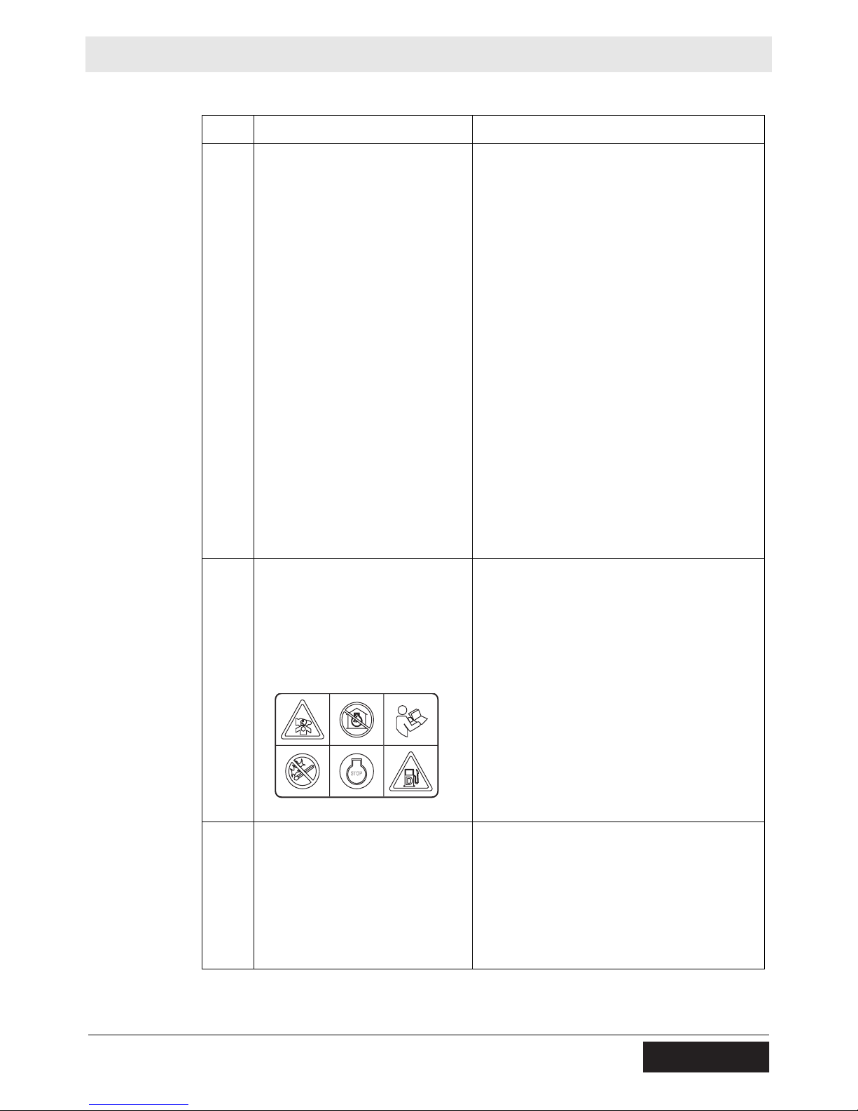
b DANGER!
Read and understand the supplied
Operator's Manuals before operating this
machine. Failure to do so increases the risk
of injury to yourself and others.
Do not run the machine indoors or in an
enclosed area without adequate ventilation.
Engine exhaust contains carbon monoxide.
This is a poison you cannot see or smell.
Exposure to carbon monoxide can cause
loss of consciousness and CAN KILL YOU IN
MINUTES.
To reduce the risk of hearing loss, wear hearing protection when operating this machine.
Always wear seat belt when operating the
machine.
Never operate the machine sideways on
slopes.
c DANGER!
Asphyxiation hazard. Do not run the machine
indoors or in an enclosed area without adequate ventilation. Read the Operator’s Manual for instructions. No sparks, flames, or
burning objects near machine. Stop the
engine before adding fuel. Use only diesel
fuel.
0178715
dCAUTION
Lifting point.
wc_si000393gb.fm 17
Page 18
Labels RD 27
Ref. Label Definition
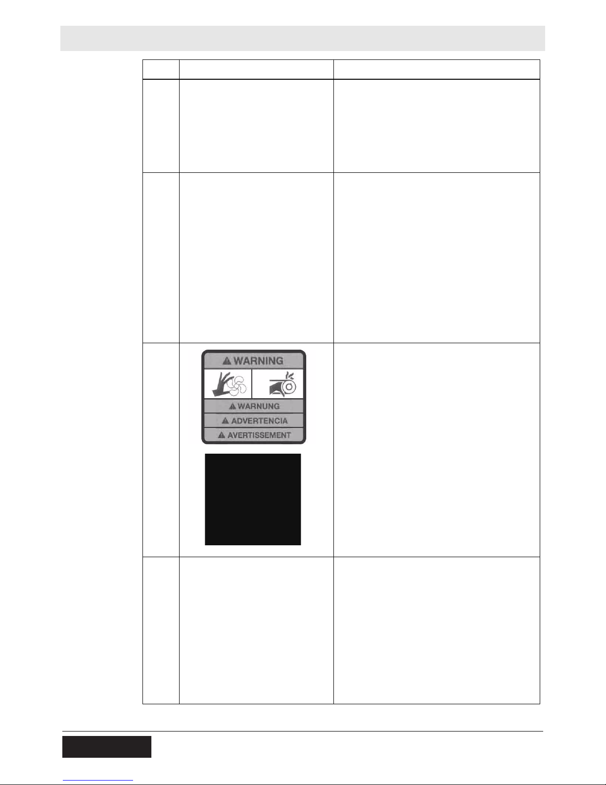
f WARNING!
Avoid crushing area.
h WARNING!
Disconnect battery before servicing.
Read Repair Manual.
Explosion hazard. Batteries can emit explosive hydrogen gas. Keep all sparks and
flames away from the battery.
lWARNING!
Pinching hazard. Rotating machinery.
m WARNING!
Pressurized contents. Do not open when hot!
18 wc_si000393gb.fm
Page 19

RD 27 Labels
Ref. Label Definition
n WARNING!
Avoid crushing area.
s WARNING!
Do not drill or weld the ROPS.
Read the Operator’s Manual.
t WARNING!
Avoid crushing area.
Articulated steering joint locking location.
Lock the articulated steering joint before servicing the machine.
Read Repair Manual.
wc_si000393gb.fm 19
Page 20

Labels RD 27
2.3 Informational Labels
Ref. Label Definition
a Operator’s Manual must be stored on
O P E R A T O R ' S M A N U A L M U S T B E
S T O R E D O N M A C H I N E .
R E P L A C E M E N T O P E R A T O R ' S
M A N U A L C A N B E O R D E R E D
L O C A L W A C K E R
T H R O U G H Y O U R
D I S T R I B U T O R .
D I E B E T R I E B S V O R S C H R I F T M U S S
A N D E R M A S C H I N E A U F B E W A H R T
W E R D E N . Z U R B E S T E L L U
E R S A T Z B Ü C H E R N W E N D E N S I E
S I C H B I T T E A N I H R E N
Ö R T L I C H E N W A C K E R H Ä N D L E R .
N G V O N
E L M A N U A L D E O P E R A C I O N D E B E
S E R R E T E N I D O E N L A M A Q U I N A .
C O N T A C T E A S U D I S T R I B U I D O R
W A C K E R M A S C E R C A N O P
P E D I R U N E J E M P L A R
A D I C I O N A L .
L A N O T I C E D ' E M P L O I D O I T
E T R E M U N I E S U R L A M A C H I N E .
C O N T A C T E R L E D I S T R I
W A C K E R L E P L U S P R O C H E
P O U R C O M M A N D E R U N
E X E M P L A I R E S U P P L E M E N T A I R E .
B U T E U R
A R A
machine. Replacement Operator’s Manual
can be ordered through your local Wacker
Neuson distributor.
1 1 5 0 9 6
e A nameplate listing the model number, item
number, revision number, and serial number
is attached to each unit. Please record the
information found on this plate so it will be
available should the nameplate become lost
or damaged. When ordering parts or
requesting service information, you will
always be asked to specify the model number, item number, revision number, and serial
number of the unit.
g Tie-down point.
i Hydraulic oil drain.
HYDRAULIC OIL
HYDRAULIKÖL
ACEITE HIDRÁULICO
HUILE HYDRAULIQUE
j Hydraulic oil reservoir fill.
20 wc_si000393gb.fm
Page 21
RD 27 Labels
Ref. Label Definition
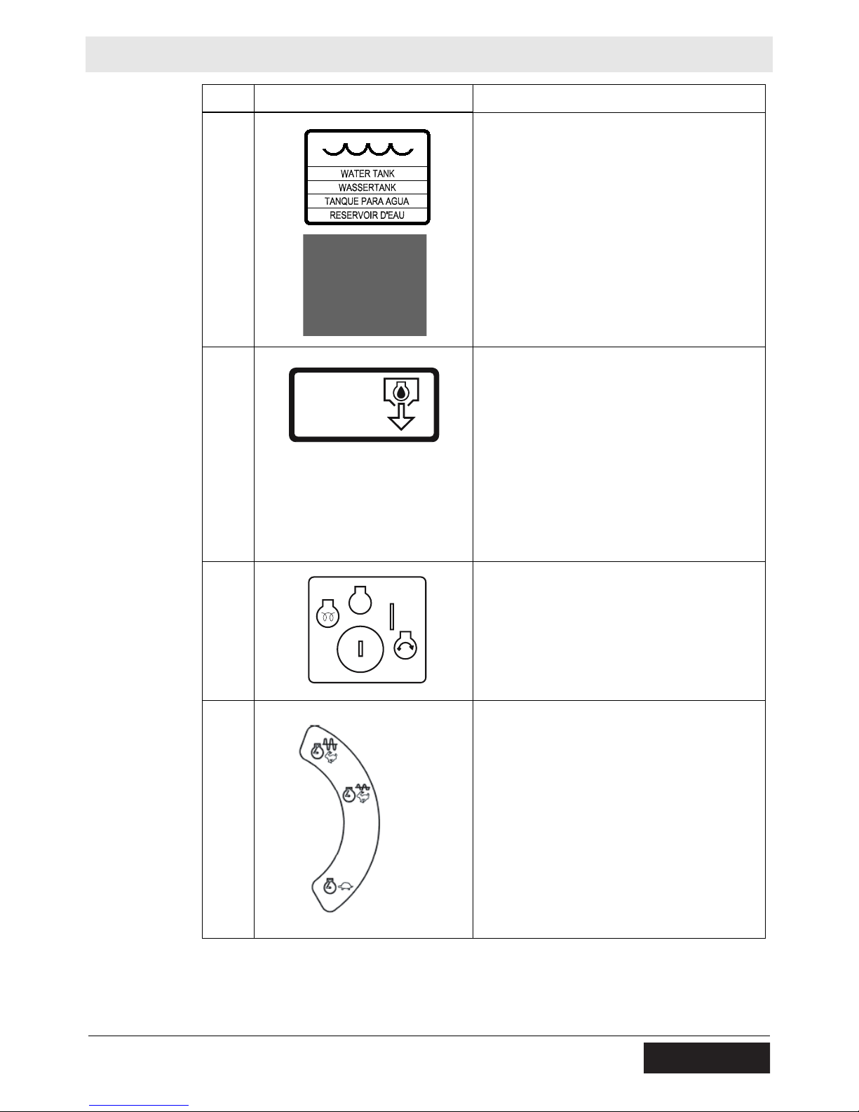
k Water tank fill.
o Engine oil drain.
ENGINE OIL
MOTOROEL
ACEITE DE MOTOR
HUILE À MOTEURS
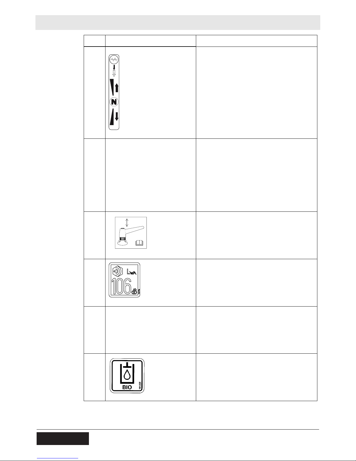
p Key switch positions.
STOP
Power to glowplugs.
Engine stopped (OFF).
Engine ON.
Power to starter motor.
q Throttle lever positions.
High speed.
Low speed.
wc_si000393gb.fm 21
Page 22
Labels RD 27
Ref. Label Definition
r Vibration activation and deactivation switch.
Forward/reverse lever positions.
u Fuse identifications.
v Tighten screw to reduce vibration.
1
2
Read Operator’s Manual.
wc_gr002757
w Guaranteed sound power level in dB(A).
x ROPS certification label
y Biodegradable hydraulic oil reservoir fill
(if equipped)
22 wc_si000393gb.fm
Page 23
RD 27 Lifting and Transporting
3 Lifting and Transporting
3.1 Lifting the Machine
Prerequisites
Procedure
Lifting equipment (crane or hoist) capable of supporting 2722 kgs. (6000 lbs.)
Four lifting hooks and chains capable of supporting 2722 kgs. (6000 lbs.)
WARNING
Crushing hazard. You may be crushed if the lifting devices fail.
f Never stand under, or get onto, the machine while it is being lifted or moved.
f Use only the designated lifting points to lift the machine.
Follow the procedure below to lift the machine.
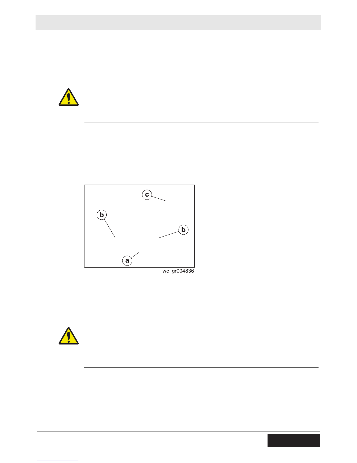
1. Stop the engine.
2. Engage the parking brake.
3. Lock the articulated steering joint (a).
4. Attach one lifting chain to each of the four lifting eyes (b) on the machine (two
per side) using hooks or shackles.
5. Attach the other end of the chains to the lifting equipment.
6. Lift the machine as necessary.
CAUTION
Crushing / machine damage hazards. The Roll Over Protection Structure (ROPS)
(c) is intended strictly to protect the operator during a rollover or tip-over incident.
The ROPS must not be used to lift the machine.
f Use only the designated lifting eyes to lift the machine.
wc_tx001351gb.fm 23
Page 24
Lifting and Transporting RD 27
3.2 Tying Down/Transporting the Machine
Prerequisites
Procedure
Engine shut down
Parking brake ON
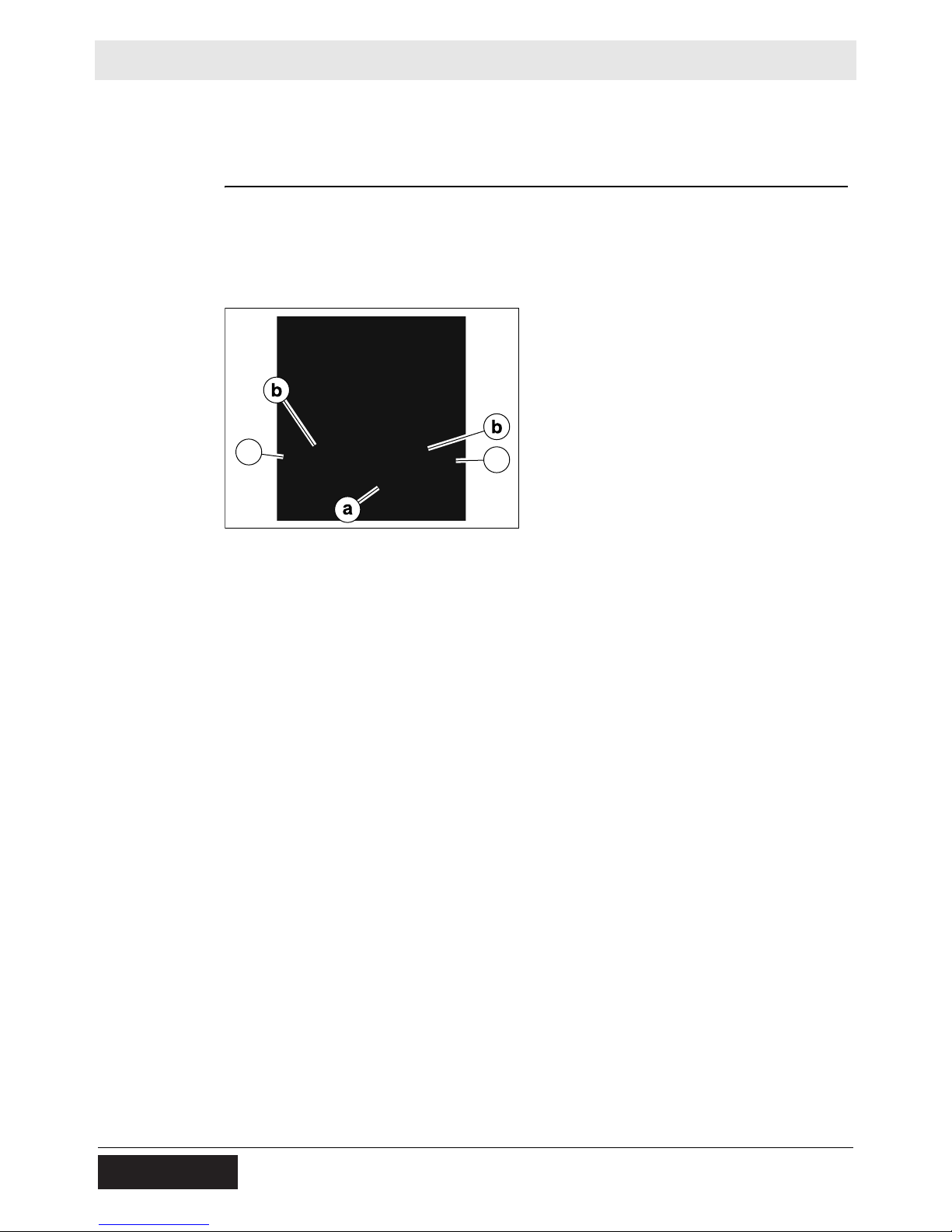
Follow the procedure below to tie down the machine.
1. Make sure that the transport vehicle is capable of handling the weight and size
of the machine. See Technical Data for dimensions and operating weight.
2. Lock the articulated steering joint (a).
c
wc_gr004992
3. Attach steel ropes or chains to each of the four tie down eyes (b) on the
machine (two per side) and the two tie down bars (c) on the front and rear of the
machine.
c
4. Attach the other end of the chains to an appropriate vehicle capable of handling
the weight of the machine.
Note: The transmission is normally braked when the diesel engine is off, or when
the hydraulic system is not functioning, unless there is a fault and/or the parking
brakes have been manually disabled.
NOTICE: Do not position ropes or chains across the machine frame or the articulated joint when tying down the machine. Damage to the machine may occur.
NOTICE: Do not completely compress the shock mounts when tying down the
machine. Damage to the shock mounts may occur.
NOTICE: Do not leave the machine tied down for extended periods of time (except
when transporting). Damage to the shock mounts may occur.
24 wc_tx001351gb.fm
Page 25

RD 27 Operation
4 Operation
4.1 Preparing the Machine for First Use
Preparing for
first use
To prepare your machine for first use:
1. Make sure all loose packaging materials have been removed from the machine.
2. Check the machine and its components for damage. If there is visible damage,
do not operate the machine! Contact your Wacker Neuson dealer immediately
for assistance.
3. Take inventory of all items included with the machine and verify that all loose
components and fasteners are accounted for.
4. Attach component parts not already attached.
5. Add fluids as needed, including fuel, engine oil, and battery acid.
6. Move the machine to its operating location.
4.2 Position of the Operator
Safe and efficient use of this machine is the operator’s responsibility. Full control of
the machine is not possible unless the operator maintains the proper working
position at all times.
While operating this machine, the operator must:
be seated in the operator’s seat facing forward
wear the seat belt, properly adjusted and latched
have both feet on the control deck
have one hand on the steering wheel at all times
have the other hand free to operate the controls as needed
wc_tx000814gb.fm 25
Page 26

Operation RD 27
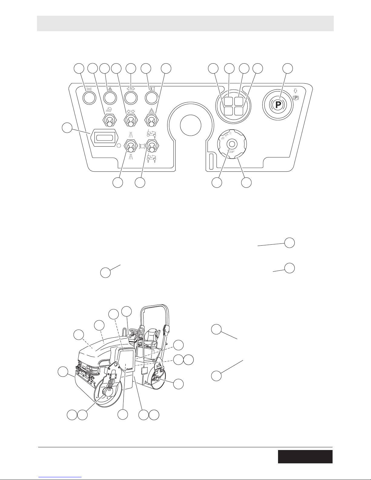
4.3 Operation & Maintenance Locations
Ref. Description Ref. Description
a Throttle lever l Vibration mode switch
b Ignition key block m Vibration ON/OFF switch
c Alternator warning light n Water pump switch
d Engine oil pressure warning light o Engine temperature warning light
e Hydraulic oil temperature warn-
ing light
f Forward-reverse lever q Turn signal switch
g Horn r Flashers ON warning light
h Parking brake warning light and
control
i Vibration-on warning light t Flow divider switch (if equipped)
j Light switch u Turn signal indicator
k Fuse box v Lights ON indicator
-- -- w Light switch
p Hour meter
s Flasher activation switch
Ref. Description Ref. Description
1 Diesel engine 7 Front exciter hydraulic motor
2 Hydraulic transmission pump 8 Rear hydraulic transmission
motor
3 Front hydraulic transmission
motor
4 Rear exciter hydraulic motor 10 Brake
5 Exciter hydraulic pump 11 Oil cooler
6 Steering hydraulic pump 12 Electric water pump
9 Servo steering
26 wc_tx000814gb.fm
Page 27
RD 27 Operation
v
rwq iu s c hode
p
n l g j
b
a
9
t
1
11
7
10
3 10
2
k
m
12
6
5
10
f
4
10
8
wc_gr005016
wc_tx000814gb.fm 27
Page 28

Operation RD 27
4.4 Unlocking/Locking the Articulated Joint
Locking
Unlocking
Install the articulated steering joint pin in the LOCKED position (a) before you lift
the machine, transport the machine, or perform maintenance near the center of the
machine.
Install the articulated steering joint pin in the UNLOCKED position (b) before you
operate the machine.
NOTICE: Attempting to steer the machine with the articulated steering joint pin in
the locked position may destroy the steering cylinder and locking mechanism.
28 wc_tx000814gb.fm
Page 29
RD 27 Operation
4.5 Using the Roll Over Protection Structure (ROPS)
Background
Positioning
The machine is equipped with a Roll Over Protection Structure (ROPS). The ROPS
is designed to protect the operator in a rollover accident.
WARNING
Crushing hazard. You may be crushed if the machine rolls over.
f Never use the machine without the ROPS in place.
Follow the procedure below to position the ROPS in the upright position.
1. Support the ROPS (a) using a crane and suitable rigging capable of supporting
70 kg (155 lbs.).
2. Remove the safety pin (b) and pull out the locking pin (c).
3. Lift the ROPS into the upright position.
4. Insert the locking pin and secure it with the safety pin.
5. Tighten the adjusting screw (d) as needed to reduce vibration.
Keep the ROPS in the extended (upright) position when using the roller.
WARNING
Crushing / machine damage hazards. The ROPS is intended strictly to protect the
operator during a rollover or tip-over incident and must not be used to lift the
machine.
f Use only the designated lifting eyes to lift the machine. See Lifting the Machine.
WARNING
Personal injury hazard. The ROPS is not a handhold for passengers. Passengers
can be seriously injured or killed from falls, tip-overs, or roll-over incidents.
f Do not allow anyone to ride on any part of the machine.
wc_tx000814gb.fm 29
Page 30

Operation RD 27
Checking
Rules for reinstalling
Each month, check:
the torque on all of the screws holding the ROPS in place
the ROPS frame for rust, cracks, and any other damage
When reinstalling the ROPS:
Use the original nuts and bolts.
Use oil to lubricate the bolts before installing the ROPS.
Tighten the bolts to the specified torques.
NOTICE: Do not weld or drill into the ROPS. Drilling or welding on the ROPS will
nullify the ROPS certification.
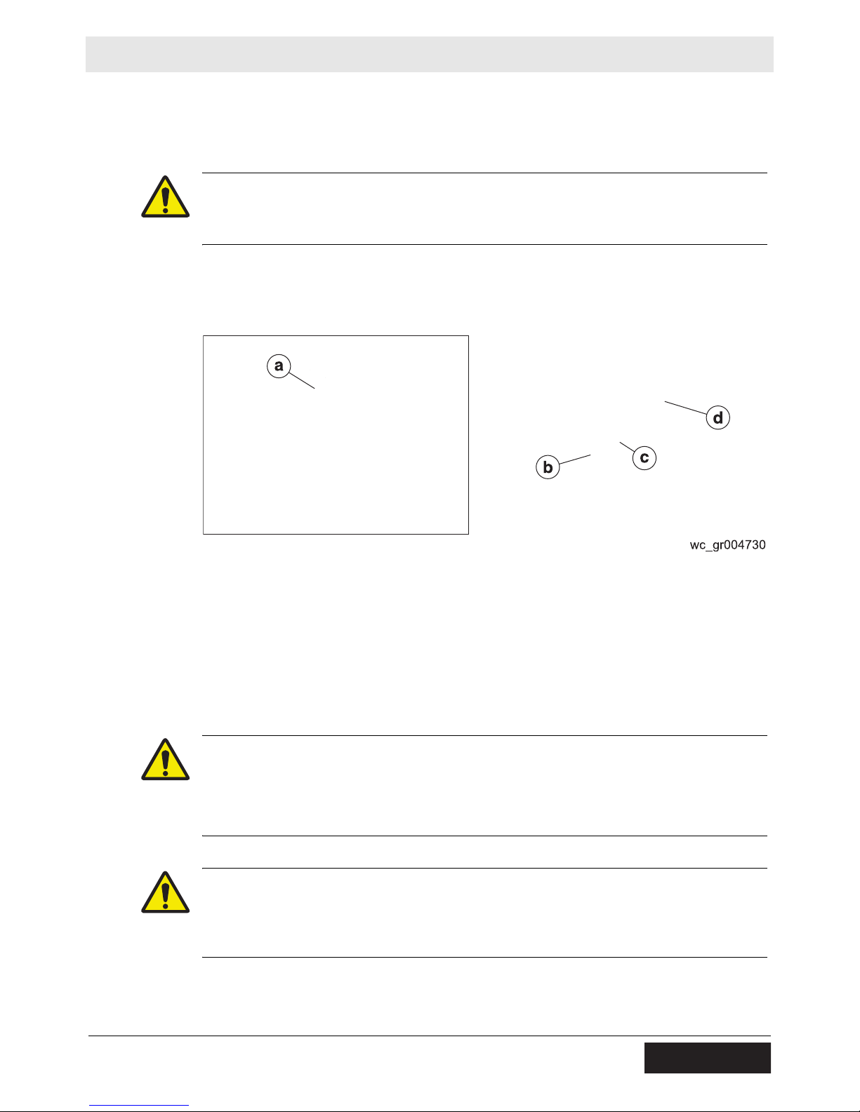
4.6 Installing the Rotating Beacon
Background
The rotating beacon illuminates and rotates when the key switch is in the ON
position.
Procedure
Follow the procedure below to install the beacon.
1. Thread the power wire (c) through the light staff and fix it to the upper connector.
a
d
b
c
wc_gr004731
2. Insert the connector into the light staff.
3. Insert the light staff assembly (a) into the left side of the machine ROPS and
tighten the set screw (b).
4. Slide the rotating beacon (d) onto the light staff.
30 wc_tx000814gb.fm
Page 31

RD 27 Operation
4.7 Using the Seat Belt
Precaution
To use
Always use the seat belt when operating the machine.
To use the seat belt:
1. Pull seat belt (c) out of the retractor in a continuous motion.
c
d
b
a
wc_gr002238
2. Fasten seat belt catch (b) into buckle (a).
3. Position the seat belt low across the lap of the operator. The retractor will adjust
the belt length and the retractor will lock in place.
4. Push the release button (d) on the buckle in order to release the seat belt. The
seat belt will automatically retract into the retractor.
wc_tx000814gb.fm 31
Page 32

Operation RD 27
4.8 Adjusting the Seat
Background
To adjust
Adjust the seat position and tension (firmness) according to working conditions and
operator’s weight.
The seat can be adjusted in three ways:
Tension Use knob (a) for adjusting seat tension. Turn from a minimum of
60 kg to a maximum of 120 kg (132 lb–264 lb).
Front to back Use lever
controls.
Side to side (optional) Use pin
ment holes (if so equipped).
(b) to adjust the front-to-back distance from the driving
(c) to set one of the three side-to-side position place-
32 wc_tx000814gb.fm
Page 33

RD 27 Operation
4.9 Adjusting the Steering Column
Background
To adjust
Adjust the angle of the steering column according to working conditions and the
operator’s height and personal preference.
The angle of the steering column can be adjusted as follows:
1. Loosen the four mounting bolts (a) at the base of the steering column.
2. Pivot the steering column forward or backward as desired.
3. Once the desired angle has been reached, re-tighten the mounting bolts.
4.10 Positioning the Scraper Bars
Prerequisites
Positions
Machine shut down
Parking brake engaged
Each drum has two scrapers (a, b). They may be set in the travel position (1) or the
scraping position (2).
wc_tx000814gb.fm 33
Page 34

Operation RD 27
4.11 Using the Anti-Vandalism Protection Devices
Background
Procedure
Parts of the machine may be subject to theft or vandalism when the machine is
unattended. These parts can be locked to prevent unauthorized access or use.
Lockable parts include:
Engine cover
Control console cover
Operator’s Manual holder
Follow the procedure below to lock the machine.
1. Close the engine cover and attach a padlock to the fastener (a).
wc_gr004735
2. Slide the control console cover over the console and attach a padlock to the
fastener (b).
3. Close the Operator’s Manual holder lid and attach a padlock to the fastener (c).
Note: Padlocks are supplied with the machine as standard.
34 wc_tx000814gb.fm
Page 35

RD 27 Operation
4.12 Using the Water Spray System
Switch
positions
Guidelines
when using
Water from the tank is fed to the spray nozzles by an electric pump. The switch
controls the water pump motor. The switch has three positions:
Position 1: activates the
intermittent water spray
Mid position (0): turns
off the water spray
0
system
Position 2: activates the
continuous water spray
When using the water spray system:
Check that the tank is full of water.
Use only clean water. Dirty water, even when filtered, can clog the system.
Keep the water system clean and well maintained. See Maintenance Section.
If spray does not begin immediately when the system is turned on, it may be
necessary to bleed air from the water lines. Opening the diaphragm valve (a)
while the system is running will force air out of the lines. Close the diaphragm
valve when water begins to spray through the nozzles.
Adjusting
To adjust the angle of spray:
Insert a screwdriver into the nozzle (b) and adjust the angle as desired.
Note: Ensure that water spray covers entire length of drum.
Draining
During winter, or when temperatures drop below 0°C (32°F), drain the water spray
system. See section Draining the Water Spray System.
wc_tx000814gb.fm 35
Page 36

Operation RD 27
4.13 Using the Forward/Reverse Lever
Background
Travel
direction
Both roller drums are driven. An infinitely variable displacement pump and
hydrostatic transmission drive the hydraulic motors fitted to each drum. The
machine moves forward or reverse by using the forward/reverse lever located to
the side of the driver’s seat.
Move the forward/reverse lever into FORWARD (f) or REVERSE (r) according to
the direction of travel desired.
To change direction of travel from FORWARD to REVERSE or vice versa:
Travel speed
Braking
Operator
present
system
1. Move the forward/reverse lever to the “N” NEUTRAL position (n).
2. Allow the machine to come to a complete stop.
3. Move the forward/reverse lever in the direction desired.
Note: In order to comply with safety standards, the machine has a device which
only enables starting of the engine when the forward/reverse lever is in the neutral
position.
Travel speed varies from “ZERO” to a permitted maximum of 10 kph (6.2 mph).
The farther forward or reverse the forward/reverse lever is positioned, the faster
the roller will travel.
Travel speed is the same in both FORWARD and REVERSE.
Note: When negotiating slopes, keep the forward/reverse lever at minimum travel
speed.
The forward/reverse lever can be used as an engine brake. Shifting the forward/
reverse lever to the neutral position stops the machine.
The machine is equipped with an operator present system. The system prevents
the machine from moving forward or reverse unless the operator is seated. The
operator should remain seated at all times.
36 wc_tx000814gb.fm
Page 37

RD 27 Operation
4.14 Backup Alarm
Location
Operation
The backup alarm (e) is located on the rear of the machine.
Start the engine and move the forward-reverse lever to the reverse position. The
backup alarm should sound immediately. The backup alarm will continue to sound
until the forward-reverse lever is moved to the neutral position or to the forward
position.
If the backup alarm does not sound, make the necessary repairs before using the
roller.
e
wc_gr005034
wc_tx000814gb.fm 37
Page 38

Operation RD 27
4.15 Using the Flow Divider (if equipped)
Background
Flow divider
switch
This machine may be equipped with an optional flow divider. Non-uniform soil
conditions, such as a combination of loose sandy material and large particles, may
cause the drums to rotate at unequal speeds. This may impede machine
movement. When activated, the flow divider equalizes the flow of hydraulic oil
traveling to each drive motor so that movement can be re-established.
The activation switch for the flow divider is foot-operated. Follow the procedure
below to activate the flow divider.
1. Locate the activation switch (a) on the operator’s platform to the right of the
steering column.
a
wc_gr005009
2. Press the activation switch once to turn the flow divider system on.
3. Press the activation switch again to turn the flow divider off.
NOTICE: The flow divider is designed for intermittent use only. Continuous use of
the flow divider will cause the hydraulic oil to become overheated, possibly
damaging the hydraulic system. Only use the flow divider if necessary to reestablish machine movement.
38 wc_tx000814gb.fm
Page 39

RD 27 Operation
4.16 Using the Vibration System
Background
Vibration
mode switch
Vibration
ON-OFF
switch
The machine has an exciter on each drum. The exciters are driven by gear-type
hydraulic motors. The exciter motors are fed by a fixed-displacement, gear-type
hydraulic pump.
Position 1: vibration of front drum
only.
Position 2: vibration of both drums.
When the switch is activated in
Position 1 or Position 2, the light (i)
on the control panel illuminates.
To start vibration, press button (m).
To stop vibration, press button (m)
again.
Frequency
NOTICE: Do not leave the vibration
running when the vehicle is to remain
stationary for some time. Leaving the
exciter on for a prolonged period
when the machine is stationary may
damage the exciter.
Note: Vibration will not run when the
forward/reverse control is in NEUTRAL.
Position 1: Use when starting or
shutting down the engine.
Position 2: Use for approximately 55
Hz of vibration.
Position 3: Use for approximately 66
Hz of vibration.
Note: Always use Position 2 or Position 3 when operating the machine.
wc_tx000814gb.fm 39
Page 40

Operation RD 27
4.17 Using the Parking Brakes
Background
To aid in holding the machine in a stopped position (parked), there is a mechanical
parking brake on each drum drive motor. The mechanical parking brakes are
spring-activated and hydraulically released (SAHR) type brakes.
The parking brakes are applied when any of the following conditions exist:
The parking brake push button (h) is pressed.
The engine is switched off.
The operator leaves the seat.
There is a fault in the hydraulic system.
h
wc_gr005010
Engaging and
releasing
Emergency
use
Pushing the button engages the parking brakes.
The “Brakes On” warning light illuminates when the button is pressed.
Pulling the button up allows the release of the parking brakes.
Note: All of the following conditions must be met for the parking brakes to release:
The engine must be running.
The forward/reverse lever must be in the neutral position.
The operator must be seated.
NOTICE: Do not use the parking brakes to stop the machine during normal
operating conditions. Using the parking brake while the machine is moving may
damage the drive motors.
Only use the parking brakes to stop the machine during an emergency condition.
For example:
During failure of the main hydraulic braking system (no braking action when the
forward/reverse lever is moved to the neutral position)
During a runaway condition traveling down a slope
40 wc_tx000814gb.fm
Page 41

RD 27 Operation
4.18 Warning Lights
Warning light Description Action Required
Engine oil pressure This light (d) illuminates
when the key switch is in
the ON position; it goes out
once the engine has
started, if engine oil pressure is OK.
Engine high temperature This light (o) illuminates
when the engine is overheating.
Alternator This light (c) illuminates
when the key switch is in
the ON position; it goes out
once the engine has
started, if the charging system is OK.
Hydraulic oil temperature This light (e) illuminates
when the hydraulic oil is too
hot.
Turn off the engine immediately if this light illuminates
when the engine is running.
Check:
Engine oil level
Engine oil viscosity
Turn off the engine immediately if this light illuminates.
Check:
Engine coolant level
Turn off the engine immediately if this light illuminates
while the engine is running.
Check:
Alternator belt
Turn off the engine immediately if this light illuminates.
Check:
Hydraulic oil level
Hydraulic oil viscosity
wc_tx000814gb.fm 41
d
o
c
e
wc_gr005012
Page 42

Operation RD 27
4.19 Using the Lights and Horn
Background
Identifying the
lights
Operating the
lights and
horn
The rotary switch on the control panel controls power to the machine’s lights.
Headlights (a)
Working light (b)
Front turn signal lights / roading lights (c)
Rear turn signal lights / roading lights (d)
dc a c d b
wc_gr005035
Position 0: all lights off
Position 1: headlights and roading lights ON
Position 2: headlights, roading lights, and work lights ON
Press the center of the switch to sound the horn.
0
1
2
wc_gr005032
WARNING
Collision hazard. Failure to use all available lights when working in the dark or in
bad visibility may increase the possibility of colliding with nearby people, vehicles,
or stationary objects.
f Use all available lights when working in the dark or in bad visibility.
f Replace broken lamps immediately.
42 wc_tx000814gb.fm
Page 43

RD 27 Operation
2
4.20 Machine Stability
WARNING
Crushing hazards. Certain job site conditions or operating practices may adversely
affect machine stability.
f
Follow the instructions below to reduce the risk of tipping or falling incidents.
Surface
conditions
Steering angle
Pay attention to changing surface conditions while operating the machine. Adjust
speed and travel direction as necessary to maintain safe operation.
Machine stability and traction may be severely reduced when operating on
uneven or rough terrain, rocky soils, or wet or loosely packed surface material.
The machine may suddenly tip, sink, or fall when moved onto surfaces that have
been newly filled with earth.
An articulated roller is more likely to tip when moving off an elevated surface if the
machine is turned away from the edge.
As shown in the illustration on the right, always turn the machine toward the
edge when moving off an elevated surface.
Travel speed
A fast moving machine is more likely to tip or fall over while making turns or
changing direction.
Reduce travel speed before turning the machine.
Drum
overhang
The machine can tip suddenly if more than half of the drum width extends beyond
the edge of the elevated surface.
Reduce travel speed and watch the drum position carefully when operating
along the edge of an elevated surface.
Keep as much of the drum on the elevated surface as possible.
Vibrating on a
compacted
surface
Activating the vibratory system on a fully compacted surface may cause the drums
to rebound and momentarily lose contact with the ground. If this occurs while the
machine is on an incline, the machine may slide.
If the drums rebound on the compacted surface, reduce vibration speed or stop
vibration entirely.
wc_tx000814gb.fm 43
wc_gr00704
Page 44

Operation RD 27
4.21 Operating on Slopes
Background
Procedure
When operating on slopes or hills, special care must be taken to reduce the risk of
personal injury or damage to the machine.
Always operate the machine up and down slopes rather than from side to side. For
safe operation and for protection of the engine, continuous duty use should be
restricted to slopes of 19° (35% grade) or less.
WARNING
Crushing hazard. Never operate the machine sideways on slopes. The machine
may tip or roll over even on stable ground.
f Operate the machine straight up and down slopes.
Surface
conditions
Pay attention to changing surface conditions while operating the machine. Adjust speed
and travel direction as necessary to maintain safe operation.
Machine stability and traction may be severely reduced when operating on uneven
or rough terrain, rocky soils, or wet or loosely packed surface material.
The machine may suddenly tip, sink, or fall when moved onto surfaces that have
been newly filled with earth.
44 wc_tx000814gb.fm
Page 45

RD 27 Operation
4.22 Preliminary Checks
Prerequisites
Before
starting
Before
operating
Machine on a flat, level surface
Before starting the machine, check the following items:
Engine coolant level
Engine oil level
Engine air filter indicator
Hydraulic oil level
Diesel fuel level
Condition of oil cooler and radiator cooling fins
Water level in tank
NOTICE: Top off the lubricating and hydraulic oil levels using products with the
grades and specifications shown in the “Lubricants” table found in the Technical
Data chapter of this Operator’s Manual. When doing so, use clean containers, funnels, etc., to avoid contamination.
Before operating the machine:
Unlock the articulated joint.
Adjust drum scraper position.
Check the machine for fluid leaks. Repair them before operating.
Check the work area for obstructions. Remove all obstructions.
Check that all handles, steps, and platforms are free of dirt, snow, grease, fuel,
or anything else which might endanger operator safety.
Allow the engine to warm up according to the following schedule:
Ambient Temperature Time (min.)
Above 0°C (32°F) 15
Below 0°C (32°F) 30*
* More time may be required if hydraulic controls are sluggish.
4.23 Mounting and Dismounting the Machine
When climbing on and off the machine, maintain a three-point contact with the
steps and the handholds.
Three-point contact can be:
two feet and one hand
one foot and two hands
wc_tx000814gb.fm 45
Page 46

Operation RD 27
4.24 Starting the Engine
DANGER
Asphyxiation hazard. Engine exhaust contains carbon monoxide which CAN KILL
YOU IN MINUTES. This is a poison that you cannot see or smell.
f Do not start the engine in enclosed spaces.
Procedure
Follow the procedure below to start the engine.
1. Sit down in the operator’s seat and fasten the seat belt.
2. Move the forward/reverse (f) lever to the NEUTRAL position.
3. Push the parking brake push button (h) to engage the parking brake.
4. Move the throttle to the LOW position (1).
5. Turn the starting key to POSITION 1. Check for power to the control panel. The
oil pressure and alternator lights should illuminate.
6. Turn the starting key to POSITION 2 and hold it there for approximately 15
seconds to supply power to the glow plugs. In warmer weather the time period
may be reduced.
7. Immediately after powering the glow plugs, turn the key to POSITION 3 to crank
the engine. When the engine fires, release the starting key to avoid straining the
starter motor.
NOTICE: Do not crank the engine for periods longer than 30 seconds. Turn the
key back to OFF and wait 15 seconds before cranking the engine again.
46 wc_tx000814gb.fm
Page 47

RD 27 Operation
4.25 Stopping the Engine
Prerequisites
Procedure
Flat surface with a suitable load-bearing capacity
Follow the procedure below to stop the engine.
1. Stop the machine on a flat surface with a suitable load bearing capacity.
2. Move the forward/reverse (f) lever to the NEUTRAL position.
3. Move the throttle lever to the LOW position (1).
NOTICE: Do not stop the engine suddenly after a lengthy period of running under
heavy loading. Allow the engine to run at low idling speed for a few minutes before
stopping it. This avoids a sudden drop in engine temperature when the engine is
stopped.
4. Push the parking brake push button (h).
5. Turn the key switch to POSITION 0 (OFF).
6. Remove the starting key before you leave the operator’s seat.
7. Chock the drums if the machine must be parked on a slope.
CAUTION
Obstruction hazard.
f Mark the machine with signs, lights, and other identification if the machine
poses an obstacle to traffic when parked.
wc_tx000814gb.fm 47
Page 48

Operation RD 27
4.26 Understanding the Operator Present System
Background
Operation
The machine is equipped with an operator present system. This system prevents
machine movement if the operator is not seated in the operator’s seat. The system
includes the seat switch and the neutral switch.
If the machine stops during operation, take the following steps to resume operation:
1. Sit in the operator’s seat.
2. Return the forward/reverse lever to the NEUTRAL position.
3. Operate the machine as normal.
Note: The seat switch is activated by operator weight when seated. Adjust the seat
tension so that the operator’s weight activates the seat switch. See section “Adjusting the Seat.”
4.27 Emergency Shutdown Procedure
If a breakdown/accident occurs while the machine is operating, follow the
procedure below.
1. Stop the engine.
2. Allow the engine and exhaust system to cool.
3. Using appropriate equipment, return the machine to an upright position if tipped
over.
4. Contact rental yard or machine owner.
48 wc_tx000814gb.fm
Page 49

RD 27 Operation
Notes:
wc_tx000814gb.fm 49
Page 50

Maintenance RD 27
5 Maintenance
5.1 Periodic Maintenance Schedule
Tasks designated with check marks may be performed by the operator. Tasks
designated with square bullet points require special training and equipment.
Interval* (hours of service)
(10) (100) (250) (500) (1000) (3000) (12,000)
Item Task
Air cleaner Clean
Backup alarm Test
Engine coolant level Check
Engine oil level Check
Fuel level Check
Hydraulic oil level Check
Neutral switch Test
Scrapers Check
Seat belt Inspect
Spray nozzles Clean
Spray system filter Clean
External hardware Check
Daily 2
weeks3 months
3
3
3
3
3
3
3
3
3
3
3
3
Yearly Yearly 3
years
6
years
Fuel system water separator
Fuel tank Drain
Throttle control Lubricate
Water tank strainer Clean
Alternator belt Check
Articulated steering joint Lubricate
Steering cylinder Lubricate
Braking system Test
Engine oil and filter Change
Clean/
Drain
water/
sediment
3
3
3
3
3
3
3
3
3
50 wc_tx000815gb.fm
Page 51

RD 27 Maintenance
Interval* (hours of service)
(10) (100) (250) (500) (1000) (3000) (12,000)
Item Task
Exciter shaft bearings Re-pack
Fuel system water separator element
Fuel tank cap and strainer Clean
Hydraulic oil filter Change
Radiator/hydraulic oil
cooler
Shock mounts Check
Battery Check
Control lever tension Adjust
Engine: mounting bolts,
valve lash, cylinder head
bolts, exhaust system
Hydraulic oil Change
Hydraulic tank breather Replace
Replace
Clean
Inspect
Daily 2
weeks3 months
Yearly Yearly 3
years
3
3
3
3
3
3
3
3
3
3
6
years
Hydraulic tank strainer Clean
Radiator filler cap Clean
ROPS and mounting hardware
Engine water pump Check
Fuel injector Test
Cooling system coolant Change
Temperature
regulator
* Use whichever comes first, calendar time or service hours.
Inspect/
torque
Replace
3
3
3
3
3
wc_tx000815gb.fm 51
Page 52

Maintenance RD 27
5.2 Major Component Locations
1
5678
2
3
4
12
13
11
8
14
10 9
15
16
17
4
wc_gr005054
52 wc_tx000815gb.fm
Page 53

RD 27 Maintenance
5.3 Major Components
Ref. Description Ref. Description
1 Forward/reverse lever 10 Seat switch solenoid
2 Hydraulic tank 11 Hydraulic oil filter
3 Oil cooler 12 Suction strainer
4 Front vibration motor 13 Suction strainer
5 Steering cylinder 14 Drive pump
6 Steering pump 15 Flow divider
7 Vibration pump 16 Flow divider solenoid
8 Hydraulic motor 17 Vibration manifold
9 Steering valve - ---
wc_tx000815gb.fm 53
Page 54

Maintenance RD 27
3
5.4 Safety-Related Spare Parts
Overview
ROPS
diagram
This machine is equipped with several features to enhance operator safety. These
include the ROPS, the seat belt, and the Operator Presence switch. For your
convenience, we have provided the following diagrams and lists of replacement
parts for these safety-related features.
For a complete list of spare parts for this machine, contact your Wacker Neuson
dealer or visit www.wackerneuson.com.
wc_gr00704
54 wc_tx000815gb.fm
Page 55

RD 27 Maintenance
ROPS parts
list
Ref. Part No. Qty. Description Measurement
1 0161542 4 Screw
2 0161617 2 Shim
4 0162243 2 Control lever
5 0174257 1 ROPS frame
7 0161769 1 Label—warning
8 0162357 2 Label
9 0162007 2 Nut M16 x 2
10 0162011 2 Bolt M16 x 2
11 0162017 4 Bolt M16 x 2 x 50
12 0162059 8 Washer
13 0161850 2 Cable
14 0161940 4 Pin
15 0162247 4 Clevis pin
wc_tx000815gb.fm 55
Page 56

Maintenance RD 27
Seat
assembly
diagram
wc_gr007044
56 wc_tx000815gb.fm
Page 57

RD 27 Maintenance
Seat
assembly
parts list
Ref. Part No. Qty. Description Measurement
1 0161620 1 Skirt replacement kit
2 0161621 1 Seat slide kit
3 0161622 1 Indicator kit
4 0161744 1 Adjustable seat kit
5 0161853 1 Seat switch kit
6 0161855 1 Seat
7 0161854 1 Arm rest kit
8 0161856 1 Seat belt kit
wc_tx000815gb.fm 57
Page 58

Maintenance RD 27
Seat switch
diagram
wc_gr007045
58 wc_tx000815gb.fm
Page 59

RD 27 Maintenance
Seat switch
parts list
Ref. Part No. Qty. Description Measurement
1 0162359 1 Wiring harness, seat
2 0161998 1 Seat assembly
3 0174165 2 Spacer
4 0174181 2 Bolt 7/16-20
5 0161879 4 Strap—mounting
6 0174353 1 Clip
7 0161903 2 Washer
8 0161925 1 Cable clip
9 0174405 1 Grommet
10 0174406 2 Lock nut 7/16-20
11 0162006 1 Washer
12 0162023 2 Washer
5.5 Maintaining the Seat and Seat Belt
Background
Maintaining
the seat and
seat belt
In order for the seat and seat belt to operate safely and properly over a long period
of time, periodic maintenance and occasional repairs are necessary. Poorly
maintained equipment can become a safety hazard!
Keep the seat clean. Dirt, dust, or harsh chemicals can damage the upholstery.
Repair holes or tears immediately.
If necessary, clean the seat belt with a mild soap solution. Do not use chemical
cleaners, as they will damage the fabric.
Periodically test the operation of the seat tension knob and the front-to-back
lever. Repair or replace worn or malfunctioning components.
If the seat does not move smoothly during adjustment, apply a small amount of
standard bearing grease (such as Shell Alvania
®
RL2 or equivalent) to the rails.
wc_tx000815gb.fm 59
Page 60

Maintenance RD 27
5.6 Checking the Air Filter Indicator
Prerequisites
When
Procedure
Engine running
Parking brake on
Every 10 hours of service or daily
l
Follow the procedure below to check the air filter indicator.
1. Open the engine compartment.
2. Start the engine.
3. Place the throttle lever in the HIGH idle position.
4. Locate the air filter indicator (a).
If the yellow piston in the air filter indicator enters the red zone, clean the air
cleaner/air filters.
5. Turn off the engine.
60 wc_tx000815gb.fm
Page 61

RD 27 Maintenance
5.7 Cleaning the Air Cleaner and Primary Air Filter Element
Prerequisites
Background
Procedure
Machine shut down
Source of clean, dry, and low-pressure (less than 207 kpA (30 psi)) compressed
air
The air intake system is equipped with a filter indicator (a), which indicates when a
filter change is required. The primary air filter element can be cleaned and reused
up to six times; after that it must be replaced.
Follow the procedure below to clean the primary air filter element.
WARNING
Fire hazard.
f Never use gasoline or low flash-point solvents for cleaning the air filter.
1. Remove the cover (b) from the air filter housing.
2. Remove the primary air filter element (c) from the air filter housing.
3. Clean inside of the air filter housing.
4. Clean the primary air filter element with low-pressure (207 kpA (30 psi))
compressed air. Blow the air through the primary air filter element from the
inside to the outside.
5. Hold the primary air filter element up to the light or pass a lamp through the
middle to check the condition of the element.
NOTICE:
Do not re-use a damaged primary air filter element. Replace it even if damage is
very slight.
Do not tap or strike the primary air filter element to clean it.
Do not wash the primary air filter element.
6. Re-install the primary air filter element (c).
7. Reassemble the cover (b), positioning the breather (d) so that it is not
obstructed.
8. Push the black rubber button (several times if need be) on top of the filter
indicator to reset it.
wc_tx000815gb.fm 61
Page 62

Maintenance RD 27
5.8 Changing the Air Filter Elements
Prerequisites
Primary filter
element
Machine shut down
New primary air filter element
New secondary air filter element if required
NOTICE: Do not use the air filters as a starting aid (e.g., ether) intake.
Follow the procedure below to change the primary air filter element.
1. Remove the cover (b) from the air filter housing.
Secondary
filter element
2. Remove the primary air filter element (c).
3. Clean the inside of the air filter housing.
4. Install the new primary air filter element.
5. Replace the cover. Position it so that the breather (d) is not obstructed.
6. Reset the filter indicator (a).
Follow the procedure below to change the secondary air filter element.
Note: Change the secondary air filter element (e) every third time the primary air
filter element is changed.
1. Remove the cover (b) from the air filter housing.
2. Remove the primary air filter element (c).
3. Remove the secondary air filter element.
4. Cover the intake port and clean inside of the air filter housing.
NOTICE: Do not allow dirt to get into the engine intake port. Damage to the engine
will result.
5. Remove the cover from the intake port and install the new secondary air filter
element.
NOTICE: The secondary filter element has two rubber seals—one wider than the
other. Make sure to insert the end with the narrow seal. Damage to the engine will
result if the filter element is inserted incorrectly.
This procedure continues on the next page.
62 wc_tx000815gb.fm
Page 63

RD 27 Maintenance
Continued from the previous page.
6. Install the new primary air filter element.
7. Replace the cover (b). Position it so that the breather (d) is not obstructed.
8. Reset the filter indicator (a).
5.9 Testing the Backup Alarm
Background
When
Testing
Procedure
The backup alarm is located on the rear of the machine.
Every 10 hours of service or daily
Follow the procedure below to test the backup alarm.
1. Turn the starting key to POSITION 1.
2. Move the forward/reverse lever to the reverse position.
The backup alarm should sound immediately. The backup alarm will continue to
sound until the forward/reverse lever is moved to the NEUTRAL position or to the
FORWARD position.
NOTICE: If the backup alarm does not sound, make the necessary repairs before
using the machine.
wc_tx000815gb.fm 63
Page 64

Maintenance RD 27
5.10 Checking the Engine Coolant Level
Prerequisites
When
Procedure
Machine shut down
Engine cool
Every 10 hours of service or daily
l
Follow the procedure below to check the engine coolant level.
WARNING
Burn hazard. Engine coolant is hot and under pressure at operating temperature. It
can cause severe personal injury.
f Check the coolant level only after the engine has been shut down and is cool.
1. Open the engine compartment.
2. Open the radiator filler cap (a) slowly in order to relieve the pressure. Remove
the filler cap after the pressure has been released.
CAUTION
Burn hazard. Coolant can contain alkali.
f Avoid coolant contact with skin and eyes.
3. Maintain the coolant level to 2.54 cm (1 in.) below the shoulder inside the fill
pipe.
4. Make sure that the coolant overflow hole (b) is clean and the overflow tube is
securely attached.
5. Inspect the radiator filler cap and filler cap seal for damage. Clean the radiator
filler cap or replace it if necessary.
6. Re-install the radiator filler cap.
64 wc_tx000815gb.fm
Page 65

RD 27 Maintenance
5.11 Checking the Engine Oil
Prerequisites
When
Procedure
Park the machine on a level surface
Shut down the machine
Apply the parking brake
Every 10 hours of service or daily
Follow the procedure below to check the engine oil.
1. Clean around the dipstick (a).
2. Extract the dipstick and check the oil level. Maintain the oil level between the
two notches on the dipstick. When full, the oil level will reach notch (c).
3. Remove the oil filler cap (b) and add oil as needed.
NOTICE: Do not overfill the machine with oil. Overfilling the engine with oil may
lead to excessively high operating temperatures.
wc_tx000815gb.fm 65
Page 66

Maintenance RD 27
5.12 Checking Hydraulic Oil Level
Prerequisites
When
Procedure
Machine shut down
Hydraulic oil warm
Every 10 hours of service or daily
l
Follow the procedure below to check the hydraulic oil level.
1. Open the engine compartment.
b
2. Observe the hydraulic oil level through the sight gauge (a).
3. If the oil level is low, open the reservoir cap (b) and fill the hydraulic oil to the
mark on the sight gauge.
66 wc_tx000815gb.fm
Page 67

RD 27 Maintenance
5.13 Checking the Neutral Switch
Prerequisites
When
Procedure
Parking brake engaged
Every 10 hours of service or daily
Follow the procedure below to check the neutral switch.
WARNING
Crush hazard. The machine may lurch forward if the neutral switch is out of adjustment while making this test.
f Be sure the area is clear of all personnel and equipment before making this test.
1. Turn off the engine.
2. Engage the parking brake.
3. Move the forward/reverse lever to the FORWARD position.
4. Hold the engine start switch in the START position.
5. Slowly move the forward/reverse lever toward the NEUTRAL position.
If the engine starts before the forward/reverse lever reaches the NEUTRAL
position, the neutral switch must be adjusted. Refer to the Repair Manual.
If the engine starts only when the forward/reverse lever is in the NEUTRAL posi-
tion, the neutral switch is OK.
wc_tx000815gb.fm 67
Page 68

Maintenance RD 27
5.14 Adjusting the Scraper Bars
Prerequisites
When
Procedure
Machine shut down
Parking brake engaged
Every 10 hours of service or daily
l
Follow the procedure below to adjust the scraper bars.
1. Loosen the bolts (a).
wc_gr004773
2. Adjust the scraper so that it touches the drum along its entire length.
3. Tighten the bolts.
68 wc_tx000815gb.fm
Page 69

RD 27 Maintenance
5.15 Inspecting the Seat Belt
Prerequisites
When
Procedure
Machine shut down
Parking brake engaged
Daily, before starting the machine.
l
Follow the procedure below to inspect the seat belt.
1. Check the seat belt mounting hardware (a) for wear and damage. Replace
damaged hardware.
2. Check the buckle (b) for wear and damage. Replace the seat belt if the buckle is
damaged.
3. Inspect the seat belt (c) for wear and damage. Replace the seat belt if it is
damaged.
Note: Replace the seat belt every three years even if none of the components
show visible wear or damage.
wc_tx000815gb.fm 69
Page 70

Maintenance RD 27
5.16 Cleaning the Water Spray Nozzles
Prerequisites
When
Procedure
Machine shut down
Clean, nonflammable solvent
Every 10 hours of service or daily
l
Follow the procedure below to clean the water spray nozzles.
1. Locate the water spray nozzles.
2. Remove the cap (a).
3. Remove the nozzle (b).
4. Remove the rubber washer (c).
5. Remove the screen assembly (d).
6. Clean the nozzle (b) and the screen assembly (d) in a clean, nonflammable
solvent.
7. Reassemble the components.
70 wc_tx000815gb.fm
Page 71

RD 27 Maintenance
5.17 Cleaning the Water Spray System Filter
Prerequisites
When
Procedure
Machine shut down
Water spray system shutoff valve in closed position
Every 10 hours of service or daily
l
Follow the procedure below to clean the water spray system filter.
1. Locate the water spray system filter assembly (a) inside the step on the right
side of the machine.
e
2. Open the drain valve (b).
3. Unscrew and remove the filter bowl (d).
4. Remove the filter (c).
5. Clean the filter with water or compressed air.
6. Clean the filter bowl with water or compressed air.
7. Check the condition of the sealing gasket (e) and replace it if necessary.
8. Re-install the filter into the filter bowl, pressing down firmly to seat it in place.
9. Re-install the filter bowl.
10.Close the drain valve.
wc_tx000815gb.fm 71
Page 72

Maintenance RD 27
5.18 Cleaning and Changing the Fuel Filter/Water Separator
Prerequisites
When
Draining
water
separator
Machine shut down
New filter
Drain every 100 hours; change element every 500 hours
Follow the procedure below to drain the fuel/water separator.
1. Open the engine compartment.
2. Position the rubber drain tube (g) so that it will drain into a receptacle outside of
the engine compartment.
g
Changing
element
3. Turn valve (e) counterclockwise to open the valve, and drain the water and the
sediment into a suitable container.
Note: Collect, store and dispose of all used fluids in accordance with current
environmental protection regulations.
4. Close the valve.
To change the fuel filter element:
1. Drain the fuel filter/water separator as stated above.
2. Hold the bowl (d) while you loosen the collar (c). Remove the bowl and the
collar (c).
3. Loosen the collar (a) and remove the fuel filter element (b).
Note: Dispose of used filters according to environmental protection regulations.
4. Clean the parts. Inspect the parts for damage. Replace damaged parts.
5. Clean the filter mounting base. Remove all of the old seal.
6. Apply a light coat of diesel fuel to the seal of the new filter element.
7. Install the new filter element and tighten by hand. Tighten the collar (a).
8. Install the bowl (d) and tighten the collar (c).
9. Pump the plunger (f) approximately three times to fill the fuel filter/water
separator with fuel.
10.Start the engine and check the fuel system for leaks.
72 wc_tx000815gb.fm
Page 73

RD 27 Maintenance
5.19 Priming the Fuel System
Prerequisites
Procedure
Machine shut down
Engine cool
l
Follow the procedure below to prime the fuel system.
1. Open the engine compartment.
2. Locate the fuel filter/water separator.
3. Push the plunger (a) to fill the filter element with fuel. Pump the plunger
approximately three times until resistance is felt. This indicates the filter element
is full of fuel.
4. Attempt to start the engine.
Continue priming if:
The engine does not start.
The engine starts but misfires.
The engine starts but emits smoke.
If the engine runs roughly, continue to run the engine at low idle until the engine
runs smoothly.
wc_tx000815gb.fm 73
Page 74

Maintenance RD 27
5.20 Draining Water and Sediment from the Fuel Tank
Prerequisites
When
Procedure
Machine shut down
Suitable container
Every 100 hours of service or every 2 weeks
l
Follow the procedure below to drain water and sediment from the fuel tank.
1. Locate the drain plug (a) under the front center of the machine.
2. Remove the drain plug and allow water and sediment to drain into a suitable
container.
Note: Collect, store and dispose of all used fluids in accordance with current environmental protection regulations.
3. Re-install the drain plug.
74 wc_tx000815gb.fm
Page 75

RD 27 Maintenance
5.21 Cleaning the Water Tank Strainer
Prerequisites
When
Procedure
Machine shut down
Every 100 hours of service or every 2 weeks
l
Follow the procedure below to clean the water tank strainer.
1. Remove the filler cap (a).
b
2. Remove the water tank strainer (b).
3. Clean the filler cap with clean water or compressed air.
4. Clean the water tank strainer with clean water or compressed air.
5. Re-install the water tank strainer.
6. Re-install the filler cap.
wc_tx000815gb.fm 75
Page 76

Maintenance RD 27
5.22 Adjusting Alternator Belt Tension
Prerequisites
When
Procedure
Machine shut down
Engine cool
Every 250 hours of service or every 3 months
l
Follow the procedure below to inspect the alternator belt.
1. Open the engine compartment.
2. Remove the fan guard and shroud.
3. Apply 110 N (25 lbs.) of force to the belt (c) midway between the pulleys.
Correctly adjusted belts will deflect 13–19 mm (1/2–3/4 in.).
4. To adjust the belt, loosen mounting bolts (a) and (b).
5. Move the alternator (d) to adjust the tension.
6. Tighten the mounting bolts (a) and (b) when the tension is correct. Torque
mounting bolt (b) to 45–55 Nm (33–41 ft.lbs.).
Note: When installing a new belt, check and adjust the belt tension after the first 30
minutes of operation.
7. Re-install the fan guard and shroud.
76 wc_tx000815gb.fm
Page 77

RD 27 Maintenance
5.23 Lubricating the Articulated Steering Joint
Prerequisites
When
Procedure
Grease gun
Machine shut down
Every 250 hours of service or every 3 months
l
Follow the procedure below to lubricate the articulated steering joint.
1. Clean the fitting caps.
2. Clean the articulated steering joint fittings (a).
3. Lubricate the articulated steering joint fittings with ten strokes from a grease
gun.
4. Lubricate the oscillation bearing (b) until grease flows out of the casting.
5. Re-install the fitting caps.
wc_tx000815gb.fm 77
Page 78

Maintenance RD 27
5.24 Lubricating the Steering Cylinder
Prerequisites
When
Procedure
Machine shut down
Grease gun
Every 250 hours of service or every 3 months
l
Follow the procedure below to lubricate the steering cylinder.
One end (a) of the steering cylinder is located in the pivot area. The other end (b) is
located on the right side of the engine compartment.
1. Clean the fittings.
2. Lubricate the fittings with a grease gun.
78 wc_tx000815gb.fm
Page 79

RD 27 Maintenance
5.25 Testing the Brake System
Prerequisites
When
Precaution
Procedure
15° slope
Every 500 hours of service or yearly
l
Use this test to determine if the parking brake is functioning on the specified slope.
This test is not intended to measure the maximum brake holding effort.
Follow the procedure below to test the braking system.
1. Position the machine on a 15° slope as shown.
2. With the engine running, place the throttle control into the LOW IDLE position
and the forward/reverse control lever in the NEUTRAL position.
3. Engage the parking brake. The machine should not move.
If the machine moves, consult Wacker Neuson Service.
wc_tx000815gb.fm 79
Page 80

Maintenance RD 27
5.26 Changing the Engine Oil and Filter
Prerequisites
When
Procedure
Engine warm
15W40 engine oil and new filter
Every 500 hours of service or yearly
Follow the procedure below to change the engine oil.
WARNING
Burn hazard. Hot oil draining from the engine can burn.
f Do not touch the hot oil.
1. Open the engine hood.
2. Locate the engine oil drain hose (c) below the frame and place a suitable
container beneath it.
3. Open the drain valve beneath the filter cartridge (d) and drain off the used oil.
Note: Collect, store and dispose of all used oil and filters in accordance with current environmental protection regulations.
4. Unscrew the filter cartridge (d) and remove it.
5. Clean the filter housing base.
6. Apply a thin coat of engine oil to the seal of the new oil filter.
7. Install the new filter cartridge and tighten by hand. When the seal contacts the
base, tighten the filter cartridge an additional 3/4 turn.
8. Remove the oil filler cap and pour in the required amount of oil.
NOTICE: Always use the correct oil type. Do not use oil brands or grades which
are not recommended.
9. Clean the oil filler cap, then re-install it.
10.Start and run the engine for a few minutes.
11.Check the oil pressure and the filter seal.
This procedure continues on the next page.
80 wc_tx000815gb.fm
Page 81

RD 27 Maintenance
Continued from the previous page.
12.Stop the engine and make the following checks:
Check the oil level and top off if necessary.
Check the new filter for leaks.
5.27 Cleaning the Fuel Tank Cap and Fuel Strainer
Prerequisites
When
Procedure
Machine shut down
Clean, nonflammable solvent
Every 500 hours of service or yearly
l
Follow the procedure below to clean the fuel tank cap and fuel strainer.
1. Open the engine compartment.
2. Remove the fuel tank cap (a).
3. Remove the fuel strainer (b).
4. Wash the fuel strainer in nonflammable solvent. Dry it with compressed air.
5. Inspect both the fuel tank cap and the fuel strainer for damage. Replace the fuel
tank cap or the fuel strainer if either is damaged.
wc_tx000815gb.fm 81
Page 82

Maintenance RD 27
5.28 Changing the Hydraulic Oil Filter
Prerequisites
When
Procedure
Hydraulic oil filter
Strap-type wrench
Suitable container
Machine parked on a flat, level surface
Every 500 hours of service or yearly
l
Follow the procedure below to change the hydraulic oil.
Note: Take care to keep the hydraulic oil and the hydraulic system clean. Dirty
hydraulic oil will reduce component performance and shorten component service
life.
1. Open the engine compartment.
2. Locate the hydraulic oil filter (a).
3. Clean the area around the hydraulic oil filter.
4. Remove the hydraulic oil filter with a strap-type wrench.
Note: Collect, store and dispose of all used oil and filters in accordance with current environmental protection regulations.
5. Clean the filter housing base. Remove any existing gasket material.
6. Apply a light coat of hydraulic oil to the gasket on the new hydraulic oil filter.
7. Screw the new hydraulic oil filter on by hand. When the seal contacts the base,
tighten the filter element an additional 3/4 turn.
8. Check the hydraulic oil level (b) and add hydraulic oil as needed.
9. Check the hydraulic oil level again the next day, or after the machine has been
run and allowed to cool down.
82 wc_tx000815gb.fm
Page 83

RD 27 Maintenance
5.29 Cleaning the Hydraulic Oil Cooler
Prerequisites
When
Procedure
Machine shut down
Parking brake engaged
Every 500 hours of service or yearly
l
Follow the procedure below to clean the hydraulic oil cooler.
1. Open the engine compartment.
2. Locate the hydraulic oil cooler (a).
3. Clean the hydraulic oil cooler using compressed air.
4. Close the engine compartment.
wc_tx000815gb.fm 83
Page 84

Maintenance RD 27
5.30 Disconnecting/Connecting the Battery
WARNING
Explosion hazard. Batteries can emit explosive hydrogen gas.
f Keep all sparks and flames away from the battery.
f Do not short-circuit battery posts.
WARNING
Battery fluid is poisonous and corrosive.
f In the event of ingestion or contact with skin or eyes, seek medical attention
immediately.
Dispose of dead batteries in accordance with local environmental regulations.
Disconnecting
Connecting
Maintaining
Precautions
To disconnect the battery:
1. Stop the machine and shut down the engine.
2. Place all electrical switches in the OFF position.
3. Disconnect the negative battery cable from the battery.
4. Disconnect the positive battery cable from the battery.
To connect the battery:
1. Connect the positive battery cable to the battery.
2. Connect the negative battery cable to the battery.
Keep battery terminals clean and connections tight.
When necessary, tighten the cables and grease the cable clamps with petro-
leum jelly.
Maintain the battery at full charge to improve cold weather starting.
Observe the following precautions to prevent serious damage to the electrical
system:
Do not disconnect the battery while the machine is running.
Do not attempt to run the machine without a battery.
Do not attempt to jump-start a machine.
In the event that the machine has a dead battery, either replace the battery with
a fully charged battery or charge the battery using an appropriate battery
charger.
84 wc_tx000815gb.fm
Page 85

RD 27 Maintenance
5.31 Adjusting the Forward/Reverse Lever
Prerequisites
When
Procedure
Machine shut down
Parking brake engaged
Every 1000 hours of service or yearly
Follow the procedure below to adjust the tension (i.e., the amount of force required
to move) of the forward/reverse lever.
1. Lift up the boot (a) of the forward/reverse lever to expose the mechanism.
2. Loosen the lock nut (b).
3. Adjust the Allen screw until the desired firmness of the forward/reverse lever is
reached, then tighten the lock nut.
4. Reposition the boot.
wc_tx000815gb.fm 85
Page 86

Maintenance RD 27
5.32 Changing the Hydraulic Oil
Prerequisites
When
Draining
Hydraulic oil
Suitable container
Machine parked on a flat, level surface
Every 1000 hours of service or yearly
l
Follow the procedure below to drain the hydraulic oil tank.
Note: Take care to keep the hydraulic oil and the hydraulic system clean. Dirty
hydraulic oil will reduce component performance and shorten component service
life.
1. Open the engine compartment.
2. Remove the hydraulic tank filler cap (b).
f
Filling
3. Remove the screen (e) from the hydraulic tank filler tube. Clean the screen with
clean, nonflammable solvent.
4. Wash the hydraulic tank filler cap and the hydraulic tank filler tube with clean,
nonflammable solvent.
5. Check the condition of the breather (a). See section Checking and Cleaning the
Hydraulic Tank Breather. If the O-ring is in good condition, clean and re-install
the breather.
6. Locate the hydraulic hose drain tube connected to the hydraulic drain valve (d).
7. Drain the hydraulic oil into a suitable container.
Note: Collect, store and dispose of all used oil and filters in accordance with current environmental protection regulations.
Follow the procedure below to fill the hydraulic oil tank.
1. Remove the two suction strainers (f) inside the hydraulic tank.
2. Install two new suction strainers into the hydraulic tank.
3. Close the hydraulic drain valve (d).
4. Install the screen (e) into the filler tube.
This procedure continues on the next page.
86 wc_tx000815gb.fm
Page 87

RD 27 Maintenance
Continued from the previous page.
5. Refill the hydraulic tank with clean, filtered hydraulic oil.
6. Check the hydraulic oil level using the sight gauge (c).
7. Re-install the hydraulic tank filler cap (b).
5.33 Checking and Cleaning the Hydraulic Tank Breather
Prerequisites
When
Procedure
Machine shut down
Clean, nonflammable solvent
Every 1000 hours of service or yearly
l
Follow the procedure below to clean the hydraulic tank breather (a).
1. Open the engine compartment.
2. Remove the breather from the hydraulic tank.
3. Clean the breather with clean, nonflammable solvent.
4. Check the condition of the O-ring (b). If the O-ring is deteriorated, replace the
breather.
5. If the O-ring is in good condition, dry the breather with compressed air.
6. Re-install the breather.
wc_tx000815gb.fm 87
Page 88

Maintenance RD 27
5.34 Cleaning the Hydraulic Oil Strainer
Prerequisites
When
Procedure
Machine shut down
Clean, nonflammable solvent
Every 1000 hours of service or yearly
l
Follow the procedure below to clean the hydraulic oil strainer.
1. Open the engine compartment.
2. Remove the hydraulic tank filler cap (a).
3. Remove the hydraulic oil strainer (b).
4. Wash the hydraulic oil strainer in nonflammable solvent. Dry it with compressed
air.
5. Re-install the hydraulic oil strainer and the hydraulic tank filler cap.
88 wc_tx000815gb.fm
Page 89

RD 27 Maintenance
5.35 Cleaning the Radiator Filler Cap
Prerequisites
When
Procedure
Machine shut down
Engine cool
Every 1000 hours of service or yearly
Follow the procedure below to clean the radiator filler cap.
WARNING
Burn hazard. At operating temperature engine coolant is hot and under pressure. It
can cause severe personal injury.
f Remove the radiator filler cap only after the engine has been shut down and is
cool.
1. Open the engine compartment.
2. Remove the radiator filler cap (a) slowly to relieve pressure.
CAUTION
Burn hazard. Coolant can contain alkali.
f Avoid coolant contact with skin and eyes.
3. Clean the radiator filler cap with a clean cloth.
4. Inspect the radiator filler cap for damage. Replace it if it is damaged.
5. Re-install the radiator filler cap.
wc_tx000815gb.fm 89
Page 90

Maintenance RD 27
5.36 Checking the Engine Water Pump
Prerequisites
When
Background
Procedure
Machine shut down
Engine cool
Every 3000 hours of service or 2 years
l
If the water pump fails, the engine will overheat which can cause:
Cracks in the cylinder head
Piston seizure
Follow the procedure below to check the engine water pump.
1. Open the engine compartment.
2. Remove the fan guard and shroud.
3. Locate the water pump (a).
4. Visually inspect the water pump for leaks.
If Then
Leaks are found, replace all seals.
There is an excessive leakage of coolant, replace the engine water pump.
5. Replace the fan cover and shroud.
90 wc_tx000815gb.fm
Page 91

RD 27 Maintenance
5.37 Changing the Cooling System Coolant
Prerequisites
When
Draining
Machine shut down
Engine cool
Every 12,000 hours of service or 6 years
l
Follow the procedure below to drain the cooling system coolant.
WARNING
Burn hazard. At operating temperature, engine coolant is hot and under pressure. It
can cause severe personal injury.
f Check the coolant level only after the engine has been shut down and is cool.
1. Open the engine compartment.
2. Open the radiator filler cap (a) slowly in order to relieve the pressure. Remove
the filler cap after the pressure has been released.
3. Place a suitable container underneath the machine.
4. Open the drain valve (b) on the bottom of the radiator and allow the coolant to
drain through the attached hose into a suitable container.
Cleaning
Follow the procedure below to clean the cooling system.
1. Close the radiator drain valve.
2. Fill the coolant system with clean water and 6–10% coolant system cleaner.
3. Install the radiator filler cap.
4. Start the engine. Run the engine for 90 minutes.
5. Stop the engine. Allow the cooling system to completely cool.
6. Open the radiator filler cap.
7. Place a suitable container underneath the machine.
8. Open the drain valve (b) on the bottom of the radiator and allow the cleaner to
drain into a suitable container.
Note: Collect, store and dispose of all used coolant in accordance with current
environmental protection regulations.
wc_tx000815gb.fm 91
Page 92

Maintenance RD 27
9. Flush the cooling system with water until the draining water is transparent.
Filling
Follow the procedure below to fill the cooling system.
1. Close the radiator drain valve.
2. Add the recommended amount of coolant to the radiator.
3. Start the engine.
4. Leave the radiator fill cap off until the thermostat opens and the coolant level
stabilizes.
5. Maintain the coolant level to 2.54 cm (1 in.) below the shoulder of the fill pipe.
6. Inspect the radiator filler cap and filler cap seal for damage. Clean the radiator
filler cap or replace it if necessary.
7. Re-install the radiator filler cap.
92 wc_tx000815gb.fm
Page 93

RD 27 Maintenance
5.38 Replacing the Water Temperature Regulator
Prerequisites
When
Procedure
Removal
Machine shut down
Engine cool
Every 3000 hours of service or every 2 years
l
Follow the procedure below to replace the water temperature regulator.
WARNING
Burn hazard. At operating temperature, engine coolant is hot and under pressure. It
can cause severe personal injury.
f Check the coolant level only after the engine has been shut down and is cool.
Follow the procedure below to remove the water temperature regulator.
1. Open the engine compartment.
2. Drain and clean the engine cooling system. See section Changing the Cooling
System Coolant. The water temperature regulator should be replaced while the
coolant system is completely drained.
3. Remove the housing (a) for the water temperature regulator.
4. Remove the gasket and remove the water temperature regulator.
Installation
Follow the procedure below to install the water temperature regulator.
Note: Water temperature regulators may be reused if they are within test specifications, are not damaged, and are free of excessive deposit buildup.
1. Install a new water temperature regulator and install a new gasket.
NOTICE: If the water temperature regulator is installed incorrectly, it will cause the
engine to overheat.
2. Install the housing for the water temperature regulator.
3. Add coolant to the radiator. See section Changing the Cooling System Coolant.
4. Install the radiator filler cap.
wc_tx000815gb.fm 93
Page 94

Maintenance RD 27
5.39 Draining the Water Spray System
Prerequisites
When
Procedure
Machine shut down
Parking brake engaged
Prior to working in or experiencing freezing conditions.
l
Follow the procedure below to drain the water tank.
1. Remove the water tank filler cap.
2. Remove the water tank drain plug (a) and drain the water.
3. Open the drain valves (b and c) located within the machine frame to drain the
water.
4. When the water is drained, turn on the water pump for 30 seconds to drain the
water pump.
5. Remove the cap (d) and diaphragm (e) from the diaphragm valve.
6. Remove the caps from the ends of the spray bars to drain the spray bars. If
desired, blow compressed air through the bars to dry them.
7. Re-install the caps to the spray bars.
8. Re-assemble the diaphragm valve.
9. Close the drain valves.
10.Re-install the water tank drain plug.
94 wc_tx000815gb.fm
Page 95

RD 27 Maintenance
5.40 Towing the Machine
Prerequisites
Limitations
Procedure
Second machine of greater size and rigid towing equipment, or
Two machines of equal size to towed machine if non-rigid towing equipment is
being used
Shielding for all machines being used
Note: The strength of the towing line or the tow bar should be at least 150 percent
of the gross weight of the towing machine.
l
The following limitations must be followed:
Limit towing to emergency situations only
Limit towing to short distances
Limit towing speed to 2 km/h (1.2 mph)
Limit tow line angle to 30°
Follow the procedure below to tow the machine.
Note: If the engine runs and the steering system and/or braking system functions,
an operator may be allowed to ride on and steer the machine being towed. In all
other cases, do not ride on the machine when it is being towed.
1. Attach shielding to the machines to protect the operators if the towing
equipment breaks.
2. Block the drums so that the machine cannot move.
3. Open the engine compartment.
4. Release the parking brakes. See section Manually Releasing the Parking
Brakes.
5. Turn the bypass valve (a) two full turns in the counterclockwise direction.
Note: Do not turn the bypass valve farther than two turns. When the bypass valve
is turned farther than two turns, oil will leak past the bypass valve.
This procedure continues on the next page.
wc_tx000815gb.fm 95
Page 96

Maintenance RD 27
Continued from the previous page.
6. Connect the tow lines at the tie down bars (b and c).
7. Attach tow lines to the towing machine.
8. Remove the blocks from the drums.
9. Tow the machine as needed.
10.Once the machine is at the desired location, block the drums.
11.Close the bypass valve by turning it two full turns in the clockwise direction.
12.Disconnect the tow lines.
96 wc_tx000815gb.fm
Page 97

RD 27 Maintenance
5.41 Manually Releasing the Parking Brakes
Prerequisites
Procedure
Machine shut down
Blocks
Follow the procedure below to manually release the parking brakes.
1. Block the drums to prevent the machine from moving.
2. Remove the two plugs from each drive motor.
3. Insert an Allen wrench into the drive motor and engage the screw. Depress the
spring inside the drive motor with the screw and turn the screw until it catches.
Repeat for the second screw of the drive motor.
NOTICE: Do not use power tools to turn the screws. Damage to the drive motor
may result.
4. Turn the screws in equal amounts until the springs are fully depressed.
5. Turn the screws approximately an additional 120° until the brakes are released.
6. Repeat the procedure for the opposite drive motor.
wc_tx000815gb.fm 97
Page 98

Maintenance RD 27
5.42 Troubleshooting
Problem / Symptom Reason Remedy
Engine does not start Empty fuel tank Refill fuel tank.
Wrong type of fuel Drain tank, change fuel fil-
ter, and refill with the proper
fuel.
Old fuel Drain tank, change fuel fil-
ter, and refill with fresh fuel.
Fuel system not primed Prime the fuel system.
Fuel filter restricted or
plugged
Battery connections are
loose or corroded, or battery is dead.
Plugged air cleaner or filter
elements
Defective starter motor Repair or replace.
Inoperative fuel solenoids
on engine
Inoperative starter relay Repair or replace.
Loose or broken electrical
connections
Engine stops by itself Empty fuel tank Refill fuel tank.
Clogged fuel filter Clean or replace.
Loose or broken fuel lines Check connections and
No vibration Defective switch or poor
connection
Replace fuel filter.
Check battery connections
or replace battery as
needed.
Clean air cleaner or replace
filter elements.
Repair or replace.
Check connections and
tighten or repair as needed.
tighten or repair as needed.
Check components and
tighten or repair as needed.
Damaged or disconnected
solenoid on vibration valve
Damaged exciter assembly Repair the assembly.
Damaged or broken exciter
motor coupling
Damaged exciter motor Repair or replace.
Damaged exciter pump Repair or replace.
Damaged exciter bearings Repair or replace.
Reconnect or repair solenoid.
Repair or replace.
98 wc_tx000815gb.fm
Page 99

RD 27 Maintenance
Problem / Symptom Reason Remedy
No travel, or travel only in
one direction
No steering Damaged steering cylinder Repair or replace.
Water leaking from spray
nozzles when machine is
shut off
Sheared pin on forward/
reverse control
Loose or broken control
cable
Damaged drive motor Repair or replace.
Damaged drive pump Repair or replace.
Defective relief valve(s) Repair or replace.
Damaged steering unit Repair or replace.
Stuck or damaged steering
relief valve
Articulating joint pin is in the
LOCKED position.
One or both of the diaphragm valves is not completely closed.
The diaphragm is worn.
Replace pin.
Tighten or replace.
Repair or replace.
Install the articulating joint
pin in the UNLOCKED position.
Close the diaphragm
valve(s) completely.
Replace the diaphragm.
wc_tx000815gb.fm 99
Page 100

Schematics RD 27
6 Schematics
6.1 Electrical Schematic
100 wc_tx000863gb.fm
 Loading...