

Page 1
Operator’s Manual
Ride-On Roller
RD 16
0178395en 005 0310
0178395EN
Page 2

Copyright
notice
© Copyright 2010 by Wacker Neuson Corporation.
All rights, including copying and distribution rights, are reserved.
This publication may be photocopied by the original purchaser of the machine. Any
other type of reproduction is prohibited without express written permission from
Wacker Neuson Corporation.
Any type of reproduction or distribution not authorized by W acker Neuson Corp oration
represents an infringement of valid copyrights. Violators will be prosecuted.
T ra d emarks
Manufacturer
All trademarks referenced in this manual are the property of their respective owners.
Wacker Neuson Corporation
N92W15000 Anthony Avenue
Menomonee Falls, WI 53051 U.S.A.
Tel: (262) 255-0500 · Fax: (262) 255-0550 · Tel: (800) 770-0957
www.wackerneuson.com
Tra n slated
instructions
This Operator’s Manual presents the original instructions. The original language of this
Operator’s Manual is American English.
Page 3

RD 16 Foreword
Foreword
Machines covered in this manual
Machine Item Number
RD 16 0620060
0620402
0620798
0620799
RD 16 IRH 0620127
Machine
documentation
Expectations
for
information in
this manual
Keep a copy of the Operator’s Manual with the machine at all times.
Use the separate Parts Book supplied with the machine to order replacement
parts.
Refer to the separate Repair Manual for detailed instructions on servicing and
repairing the machine.
If you are missing any of these documents, please contact Wacker Neuson
Corporation to order a replacement or visit www.wackerneuson.com.
When ordering parts or requesting service information, be prepared to provide
the machine model number, item number, revision number, and serial number.
This manual provides information and procedures to safely operate and main-
tain the above Wacker Neuson model(s). For your own safety and to reduce
the risk of injury, carefully read, understand, and observe all instructions
described in this manual.
Wacker Neuson Corporation expressly reserves the right to make technical
modifications, even without notice, which improve the performance or safety
standards of its machines.
The information contained in this manual is based on machines manufactured
up until the time of publication. Wacker Neuson Corporation reserves the right
to change any portion of this information without notice.
CALIFORNIA
Proposition
65 Warning
Laws
pertaining to
spark
arresters
Engine exhaust, some of its constituents, and certain vehicle components, contain
or emit chemicals known to the State of California to cause cancer and birth
defects or other reproductive harm.
NOTICE: State Health Safety Codes and Public Resources Codes specify that in
certain locations spark arresters be used on internal combustion engines that use
hydrocarbon fuels. A spark arrester is a device designed to prevent accidental discharge of sparks or flames from the engine exhaust. Spark arresters are qualified
and rated by the United States Forest Service for this purpose. In order to comply
with local laws regarding spark arresters, consult the engine distributor or the local
Health and Safety Administrator.
wc_tx001346gb.fm 3
Page 4

Foreword RD 16
Manufacturer’s
approval
This manual contains references to approved parts, attachments, and modifications. The following definitions apply:
Approved parts or attachments are those either manufactured or provided by
Wacker Neuson.
Approved modifications are those performed by an authorized Wacker Neu-
son service center according to written instructions published by Wacker Neuson.
Unapproved parts, attachments, and modifications are those that do not
meet the approved criteria.
Unapproved parts, attachments, or modifications may have the following consequences:
Serious injury hazards to the operator and persons in the work area
Permanent damage to the machine which will not be covered under warranty
Contact your Wacker Neuson dealer immediately if you have questions about
approved or unapproved parts, attachments, or modifications.
4 wc_tx001346gb.fm
Page 5

RD 16 Table of Contents
Foreword 3
1 Safety Information 9
1.1 Signal Words found in this Manual ....................................................... 9
1.2 Machine Description and Intended Use ............................................. 10
1.3 Operating Safety ................................................................................ 12
1.4 Operator Safety while using Internal Combustion Engines ................ 14
1.5 Service Safety .................................................................................... 15
2 Labels 18
2.1 Label Locations .................................................................................. 18
2.2 Safety Labels ...................................................................................... 19
2.3 Informational Labels ........................................................................... 25
3 Operation 28
3.1 Operation and Service Locations ....................................................... 28
3.2 Control Panel ...................................................................................... 30
3.3 Roll Over Protection Structure (ROPS) .............................................. 32
3.4 Foldable Roll Over Protection Structure (ROPS) (if equipped) .......... 33
3.5 Rotating Beacon (if equipped) ............................................................ 35
3.6 Backup Alarm (if equipped) ................................................................ 35
3.7 Lighting Equipment (if equipped) ........................................................ 36
3.8 Seat Belt ............................................................................................. 37
3.9 Operator Presence System ................................................................ 38
3.10 Scraper Bars ...................................................................................... 39
3.11 Anti-Vandalism Protection and Machine Access ................................ 40
3.12 Articulation Joint Lockarm .................................................................. 41
3.13 Machine Stability ................................................................................ 42
3.14 Operation on Slopes ........................................................................... 44
3.15 Recommended Fuel ........................................................................... 44
3.16 Position of the Operator ..................................................................... 45
3.17 Preparing the Machine for First Use ................................................... 45
3.18 Before Starting ................................................................................... 47
3.19 Starting ............................................................................................... 48
3.20 Stopping/Parking ................................................................................ 50
wc_bo0178395en_005TOC.fm 5
Page 6

Table of Contents RD 16
3.21 Parking Brake Button ..........................................................................51
3.22 Direction and Speed ............................................................................52
3.23 Transmission .......................................................................................53
3.24 Vibration ..............................................................................................54
3.25 Water Spray System ...........................................................................55
3.26 Emergency Shutdown Procedure ........................................................56
3.27 Battery Disconnect ..............................................................................57
3.28 Auxiliary Battery Positive Terminal ......................................................57
3.29 Panel Indicator Lights ..........................................................................58
3.30 Turn Signal/Hazard Lights (if equipped) ..............................................60
4 Maintenance 62
4.1 Engine Maintenance Schedule ............................................................62
4.2 Roller Maintenance Schedule .............................................................63
4.3 Safety-Related Spare Parts .................................................................64
4.4 Maintaining the Seat and the Seat Belt ...............................................68
4.5 Cleaning the Spray Bars .....................................................................69
4.6 Rear Frame Access .............................................................................70
4.7 Fuel Filter ............................................................................................71
4.8 Priming the Fuel System .....................................................................71
4.9 Battery .................................................................................................72
4.10 Engine Oil and Filter ............................................................................74
4.11 Engine Air Cleaner ..............................................................................75
4.12 Grease Fittings ....................................................................................76
4.13 Hydraulic System Cleanliness .............................................................77
4.14 Hydraulic Oil Requirements .................................................................78
4.15 Hydraulic Oil Level ..............................................................................79
4.16 Hydraulic Suction Strainer ...................................................................79
4.17 Changing the Hydraulic Oil & Filter .....................................................80
4.18 Bleeding the Hydraulic System ...........................................................80
4.19 Lifting the Machine ..............................................................................81
4.20 Tying Down and Transporting the Machine .........................................82
4.21 Storage ................................................................................................83
4.22 Towing .................................................................................................84
4.23 Manually Releasing Parking Brake .....................................................86
4.24 Troubleshooting ...................................................................................88
6 wc_bo0178395en_005TOC.fm
Page 7

RD 16 Table of Contents
5 Schematics 90
5.1 Hydraulic Schematic ........................................................................... 90
5.2 Hydraulic Schematic Components ..................................................... 91
5.3 Electrical Schematic—RD 16 ............................................................. 92
5.4 Electrical Schematic Components—RD 16 ........................................ 94
5.5 Electrical Schematic—RD 16 IRH ...................................................... 96
5.6 Electrical Schematic Components—RD 16 IRH ................................. 98
6 Technical Data 99
6.1 Engine ................................................................................................ 99
6.2 Roller ................................................................................................ 100
6.3 Dimensions mm (in.) ........................................................................ 101
6.4 Sound Measurements ...................................................................... 102
6.5 Measurements of Operator Exposure to Vibration ........................... 102
6.6 Hydraulic Pressures ......................................................................... 103
wc_bo0178395en_005TOC.fm 7
Page 8

Table of Contents RD 16
8 wc_bo0178395en_005TOC.fm
Page 9

RD 16 Safety Information
1 Safety Information
1.1 Signal Words found in this Manual
This is the safety alert symbol. It is used to alert you to potential personal hazards.
f Obey all safety messages that follow this symbol.
DANGER
DANGER indicates a hazardous situation which, if not avoided, will result in death
or serious injury.
f To avoid death or serious injury from this type of hazard, obey all safety mes-
sages that follow this signal word.
WARNING
WARNING indicates a hazardous situation which, if not avoided, could result in
death or serious injury.
f To avoid possible death or serious injury from this type of hazard, obey all
safety messages that follow this signal word.
CAUTION
CAUTION indicates a hazardous situation which, if not avoided, could result in
minor or moderate injury.
f To avoid possible minor or moderate injury from this type of hazard, obey all
safety messages that follow this signal word.
NOTICE: Used without the safety alert symbol, NOTICE indicates a
situation which, if not avoided, could result in property damage.
Note: A Note contains additional information important to a procedure.
wc_si000399gb.fm 9
Page 10

Safety Information RD 16
1.2 Machine Description and Intended Use
This machine is a dual drum, ride-on roller. The Wacker Neuson RideOn Roller consists of an articulated frame onto which is mounted a
gasoline or diesel engine, a fuel tank, a hydraulic tank, a water tank, a
hydrostatic drive system, two steel drums containing internal eccentric
weights, and an operator’s platform with a ROPS (Roll Over Protective
Structure). The engine powers the hydraulic systems that provide
machine movement and drum vibration. The vibrating drums smooth
and compact the work surface as the machine moves. Machine speed,
direction, and vibration are controlled by the operator from the
operator’s seat on the platform.
The machine is designed as a lightweight roller to be used in the
compaction of sublayers and finish layers of asphalt on roads,
driveways, parking lots, and other types of asphalt-covered surfaces.
This machine has been designed and built strictly for the intended use
described above. Using the machine for any other purpose could
permanently damage the machine or seriously injure the operator or
other persons in the area. Machine damage caused by misuse is not
covered under warranty.
The following are some examples of misuse:
• Using the machine as a ladder, support, or work surface
• Using the machine to carry or transport passengers or equipment
• Using the machine to tow other machines
• Using the machine to spray liquids other than water (i.e., diesel
fuel on asphalt)
• Operating the machine outside of factory specifications.
• Operating the machine in a manner inconsistent with all warnings
found on the machine and in the Operator’s Manual.
This machine has been designed and built in accordance with the
latest global safety standards. It has been carefully engineered to
eliminate hazards as far as practicable and to increase operator
safety through protective guards and labeling. However, some risks
may remain even after protective measures have been taken. They
are called residual risks. On this machine, they may include exposure
to:
• Heat, noise, exhaust, and carbon monoxide from the engine
• Burns from hot hydraulic fluid
• Fire hazards from improper refueling techniques
• Fuel and its fumes
10 wc_si000399gb.fm
Page 11

RD 16 Safety Information
• Personal injury from improper lifting techniques
• Crushing hazards from improper operation (feet, legs, or arms
extending outside of the operator work station) and for other persons in the work zone
• Line of sight blockage by the ROPS
To protect yourself and others, make sure you thoroughly read and
understand the safety information presented in this manual before
operating the machine.
wc_si000399gb.fm 11
Page 12

Safety Information RD 16
1.3 Operating Safety
Familiarity and proper training are required for the safe operation of the
machine. Machines operated improperly or by untrained personnel
can be hazardous. Read the operating instructions contained in this
WARNING
1.3.1 Operator qualifications
manual and the engine manual, and familiarize yourself with the
location and proper use of all controls. Inexperienced operators should
receive instruction from someone familiar with the machine before
being allowed to operate it.
Only trained personnel are permitted to start, operate, and shut down
the machine. They also must meet the following qualifications:
• have received instruction on how to properly use the machine
• are familiar with required safety devices
The machine must not be accessed or operated by:
• children
• people impaired by alcohol or drugs
1.3.2 Contact Wacker Neuson for additional training if necessary.
1.3.3 Personal Protective Equipment (PPE)
Wear the following Personal Protective Equipment (PPE) while
operating this machine:
• Close-fitting work clothes that do not hinder movement
• Safety glasses with side shields
• Hearing protection
• Safety-toed footwear
1.3.4 Do not drive off curbs or other uneven surfaces that will result in jarring
impacts to the machine and operator.
1.3.5 DO NOT attempt to start the machine when standing alongside it. Only
start the engine when seated in the driver's seat and with the forward/
reverse control in the neutral position.
1.3.6 Do not touch the engine or muffler while the engine is on or
immediately after it has been turned off. These areas get hot and may
cause burns.
1.3.7 Do not operate the machine with unapproved accessories or
attachments.
1.3.8 Never leave the machine running unattended.
1.3.9 NEVER operate the machine with the fuel cap loose or missing.
12 wc_si000399gb.fm
Page 13

RD 16 Safety Information
1.3.10 Stay clear of the articulated steering joint and the area between the
front and rear frames.
1.3.11 NEVER use or attempt to repair damaged safety belts or ROPS.
Replace only with Wacker Neuson spare parts.
1.3.12 ALWAYS disengage and stow the locking bar for the articulated
steering joint before operating the machine. The machine cannot be
steered when the locking bar is engaged.
1.3.13 ALWAYS check that all controls are functioning properly immediately
after start-up! DO NOT operate the machine unless all controls operate
correctly.
1.3.14 ALWAYS remain aware of changing positions and the movement of
other equipment and personnel on the job site.
1.3.15 Always remain seated and wear the seat belt at all times while
operating the machine.
1.3.16 ALWAYS remain aware of changing surface conditions and use extra
care when operating over uneven ground, on hills, or over soft or
coarse material. The machine could shift or slide unexpectedly.
1.3.17 ALWAYS use caution when operating the machine near the edges of
pits, trenches or platforms. Check to be sure that ground surface is
stable enough to support the weight of the machine with operator and
that there is no danger of the roller sliding, falling or tipping.
1.3.18 Always keep hands, feet, and loose clothing away from moving parts
of the machine.
1.3.19 Store the machine properly when it is not being used. The machine
should be stored in a clean, dry location out of the reach of children.
1.3.20 Always operate machine with all safety devices and guards in place
and in working order. Do not modify or defeat safety devices. Do not
operate machine if any safety devices or guards are missing or
inoperative.
1.3.21 Do not operate a machine in need of service or repair.
Do not use a cellphone or send text messages while operating this
machine.
wc_si000399gb.fm 13
Page 14

Safety Information RD 16
1.4 Operator Safety while using Internal Combustion Engines
WARNING
Internal combustion engines present spe c ial hazards during operation and fueling.
Failure to follow the warnings and safety standards could result in severe injury or death.
f Read and follow the warning instructions in the engine owner’s manual and the
safety guidelines below.
DANGER
Exhaust gas from the engine contains carbon monoxide, a deadly poison.
Exposure to carbon monoxide can kill you in minutes.
f NEVER operate the machine inside an enclosed area, such as a tunnel, unless
adequate ventilation is provided through such items as exhaust fans or hoses.
Operating safety
When running the engine:
• Keep the area around exhaust pipe free of flammable materials.
• Check the fuel lines and the fuel tank for leaks and cracks before
starting the engine. Do not run the machine if fuel leaks are
present or the fuel lines are loose.
When running the engine:
• Do not smoke while operating the machine.
• Do not run the engine near sparks or open flames.
• Do not touch the engine or muffler while the engine is running or
immediately after it has been turned off.
• Do not operate a machine when its fuel cap is loose or missing.
• Do not start the engine if fuel has spilled or a fuel odor is present.
Move the machine away from the spill and wipe the machine dry
before starting.
Refueling safety
When refueling the engine:
• Clean up any spilled fuel immediately.
• Refill the fuel tank in a well-ventilated area.
• Replace the fuel tank cap after refueling.
• Do not smoke.
• Do not refuel a hot or running engine.
• Do not refuel the engine near sparks or open flames.
14 wc_si000399gb.fm
Page 15

RD 16 Safety Information
• Do not refuel if the machine is positioned in a truck fitted with a
plastic bed liner. Static electricity can ignite the fuel or fuel
vapors.
1.5 Service Safety
A poorly maintained machine can become a safety hazard! In order
for the machine to operate safely and properly over a long period of
time, periodic maintenance and occasional repairs are necessary.
WARNING
1.5.1 Personal Protective Equipment (PPE)
Wear the following Personal Protective Equipment (PPE) while
servicing or maintaining this machine:
• Close-fitting work clothes that do not hinder movement
• Safety glasses with side shields
• Hearing protection
• Safety-toed footwear
In addition, before servicing or maintaining the machine:
• Tie back long hair.
• Remove all jewelry (including rings).
1.5.2 Service training
Before servicing or maintaining the machine:
• Read and understand the instructions contained in all manuals
delivered with the machine.
• Familiarize yourself with the location and proper use of all con-
trols and safety devices.
• Only trained personnel shall troubleshoot or repair problems
occurring with the machine.
• Contact Wacker Neuson Corporation for additional training if nec-
essary.
When servicing or maintaining this machine:
• Do not allow improperly trained people to service or maintain the
machine. Personnel servicing or maintaining the machine must
be familiar with the associated potential risks and hazards.
1.5.3 Some service procedures require that the machine’s battery be
disconnected. To reduce the risk of personal injury, read and
understand the service procedures before performing any service to
the machine.
wc_si000399gb.fm 15
Page 16

Safety Information RD 16
1.5.4 All adjustments and repairs MUST be completed before operation. Do
not operate the machine with a known problem or deficiency! All
repairs and adjustments should be completed by a qualified
technician.
1.5.5 Do not attempt to clean or service the machine while it is running.
Rotating parts can cause severe injury.
1.5.6 Do not use gasoline or other types of fuels or flammable solvents to
clean parts, especially in enclosed areas. Fumes from fuels and
solvents can become explosive.
1.5.7 Do not modify the machine without the express written approval of the
manufacturer.
1.5.8 Do not remove the radiator cap when the engine is running or hot. The
radiator fluid is hot and under pressure and may cause severe burns!
1.5.9 DO NOT stand under the machine while it is being hoisted or moved.
1.5.10 DO NOT get onto the machine while it is being hoisted or moved.
1.5.11 DO NOT modify, weld, or drill safety frames (ROPS) fitted as original
equipment. DO NOT loosen or remove bolts. DO NOT weld, drill or
modify a broken safety frame.
1.5.12 Do not open the hydraulic lines or loosen the hydraulic connections
while the engine is running! Hydraulic fluid under pressure can
penetrate the skin, cause burns, blind, or create other personal injury
hazards.
1.5.13 ALWAYS check all external fasteners at regular intervals.
1.5.14 Keep the machine clean and labels legible. Replace all missing and
hard-to-read labels. Labels provide important operating instructions
and warn of dangers and hazards.
1.5.15 ALWAYS do periodic maintenance as recommended in the Operator’s
Manual.
1.5.16 ALWAYS turn engine off before servicing machine. If the engine has
electric start, disconnect negative terminal on battery.
1.5.17 ALWAYS keep hands, feet and loose clothing away from moving parts.
1.5.18 ALWAYS make sure slings, chains, hooks, ramps, jacks, and other
types of lifting devices are attached securely and have enough weightbearing capacity to lift or hold the machine safely. Always remain
aware of the location of other people in the area when lifting the
machine.
1.5.19 Always make sure hose connections have been reconnected back to
the correct fitting. Failure to do so may result in damage to the machine
and/or injury to person on or near the machine.
1.5.20 ALWAYS secure the articulated steering joint using the locking bar
before lifting, jacking, and servicing the machine. The machine halves
could swing together unexpectedly and cause a serious injury.
16 wc_si000399gb.fm
Page 17

RD 16 Safety Information
1.5.21 ALWAYS lock the lifting cylinders in the open position when the seat
pedestal is raised.
1.5.22 Before you start the machine, ensure that all tools have been removed
from the machine and that replacement parts and adjusters are firmly
tightened.
1.5.23 Fluid leaks from small holes are often practically invisible. DO NOT use
your bare hands to check for leaks. Check for leaks using a piece of
cardboard or wood.
1.5.24 DO NOT remove air cleaner cover, paper element, or precleaner while
engine is running.
1.5.25 ALWAYS replace the safety devices and guards after repairs and
maintenance.
1.5.26 When replacement parts are required for this machine, use only
Wacker Neuson replacement parts or those parts equivalent to the
original in all types of specifications, such as physical dimensions,
type, strength, and material.
wc_si000399gb.fm 17
Page 18
Labels RD 16
2Labels
2.1 Label Locations
GG
FF
18 wc_si000400gb.fm
Page 19
RD 16 Labels
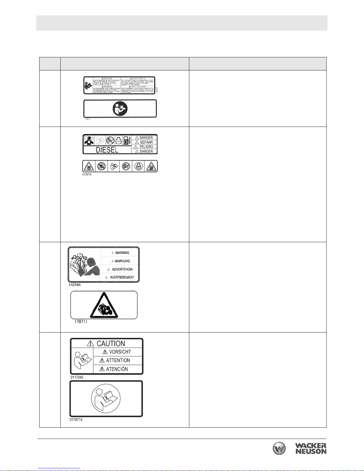
2.2 Safety Labels
Ref. Label Meaning
A
B
D
WARNING!
Read and understand the supplied Operator’s
Manual before operating the machine. Failure to
do so increases the risk of injury to yourself and
others.
DANGER!
Asphyxiation hazard.
Engines emit carbon monoxide.
Do not run the machine indoors or in an
enclosed area unless adequate
ventilation, through such items as exhaust
fans or hoses, is provided.
Read the Operator’s Manual.
No sparks, flames, or burning objects near
the machine.
Stop the engine before refueling.
Use only clean, filtered diesel fuel.
WARNING!
Pressurized contents. Do not open when hot!
E
wc_si000400gb.fm 19
CAUTION!
Read and understand the supplied Operator’s
Manual before operating this machine. Failure to
do so increases the risk of injury to yourself and
others.
Page 20
Labels RD 16
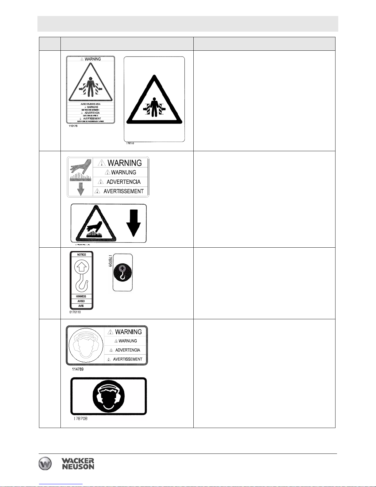
Ref. Label Meaning
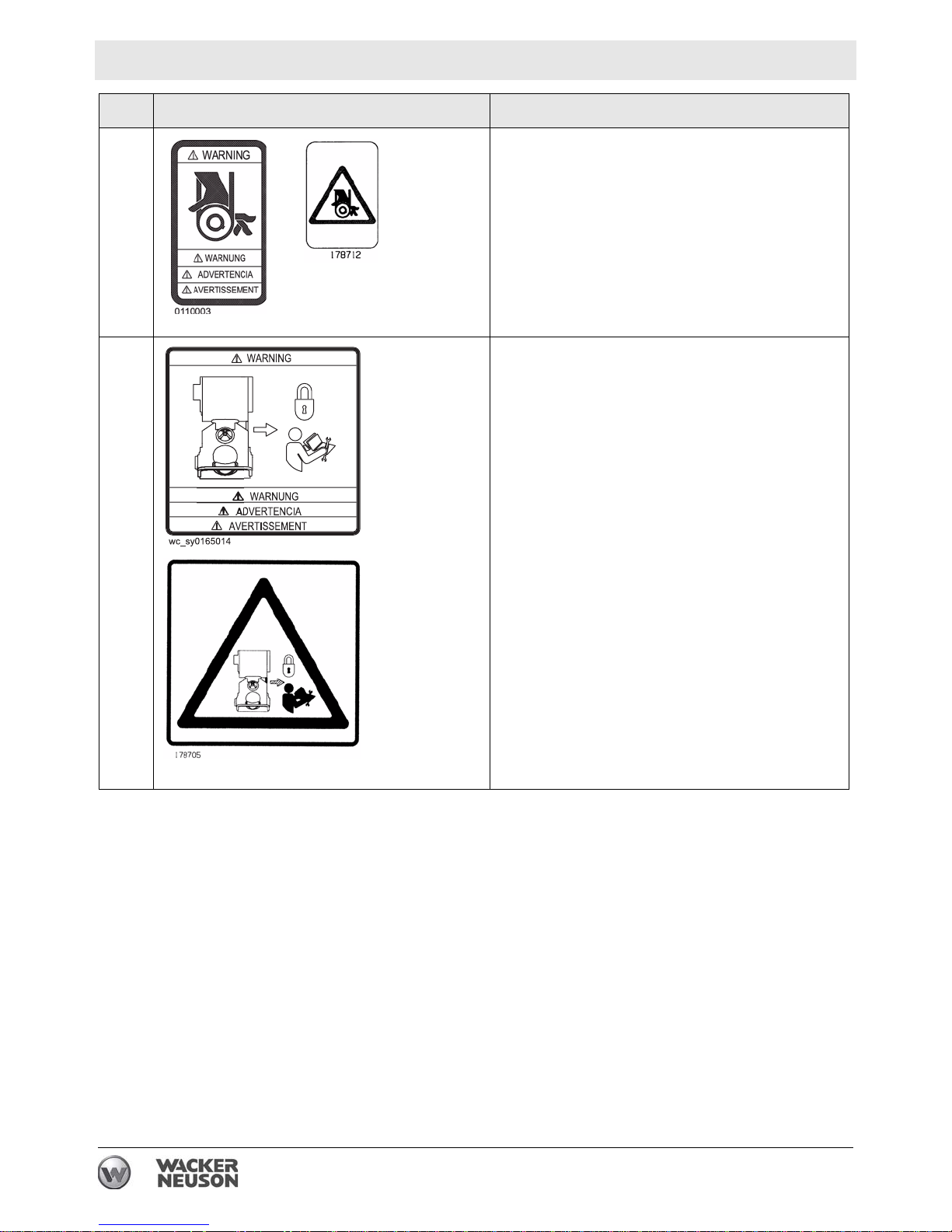
F
G
WARNING!
Pinch point.
WARNING!
Hot surface!
K
J
NOTICE
Lifting point.
WARNING
To reduce the risk of hearing loss, always wear
hearing protection when operating this machine.
20 wc_si000400gb.fm
Page 21

RD 16 Labels
Ref. Label Meaning
L
M
WARNING
Entanglement hazard. Rotating machinery.
Do not reach inside machine when engine is
running.
WARNING!
Disconnect battery before servicing.
Read Repair Manual for instructions.
Battery contains caustic acid and potentially
explosive hydrogen gas.
N
O
WARNING!
Always wear seat belt when operating roller.
WARNING!
Avoid crushing area.
wc_si000400gb.fm 21
Page 22
Labels RD 16
Ref. Label Meaning
P
V
WARNING
Entanglement hazard. Rotating machinery.
Do not reach inside machine when engine is
running.
WARNING!
Avoid crushing area.
Articulated steering joint locking location. Lock
the articulated steering joint before servicing the
machine.
Read Repair Manual.
22 wc_si000400gb.fm
Page 23
RD 16 Labels
Ref. Label Meaning
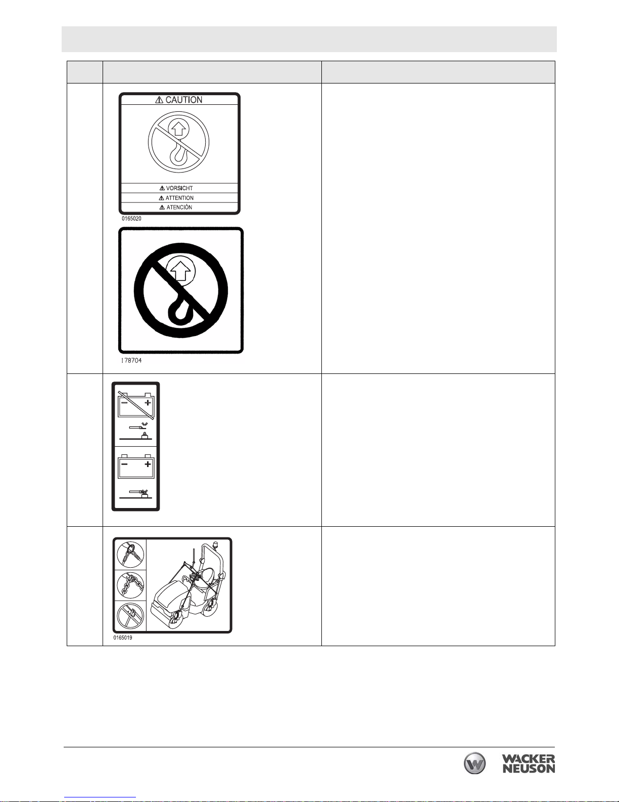
Z
AA
No lift point.
WARNING!
Disconnect battery before servicing.
0165018
BB
wc_si000400gb.fm 23
Lifting of machine to be done with spreader bar
only!
Page 24
Labels RD 16
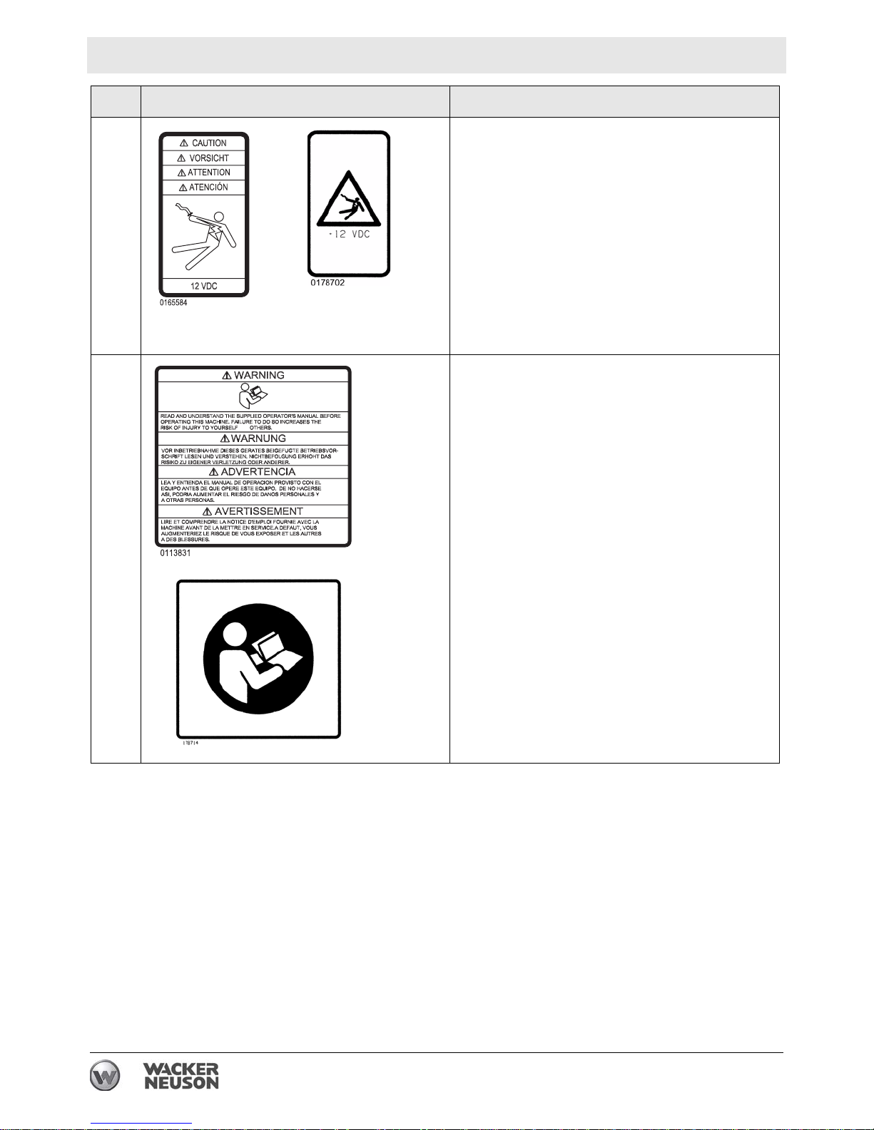
Ref. Label Meaning
CC
DD
CAUTION! Electric shock hazard at auxiliary battery positive terminal. Never touch this terminal
and a metal portion of the machine simultaneously.
WARNING!
Read and understand the supplied Operator’s
Manual before operating the machine. Failure to
AND
do so increases the risk of injury to yourself and
others.
24 wc_si000400gb.fm
Page 25
RD 16 Labels
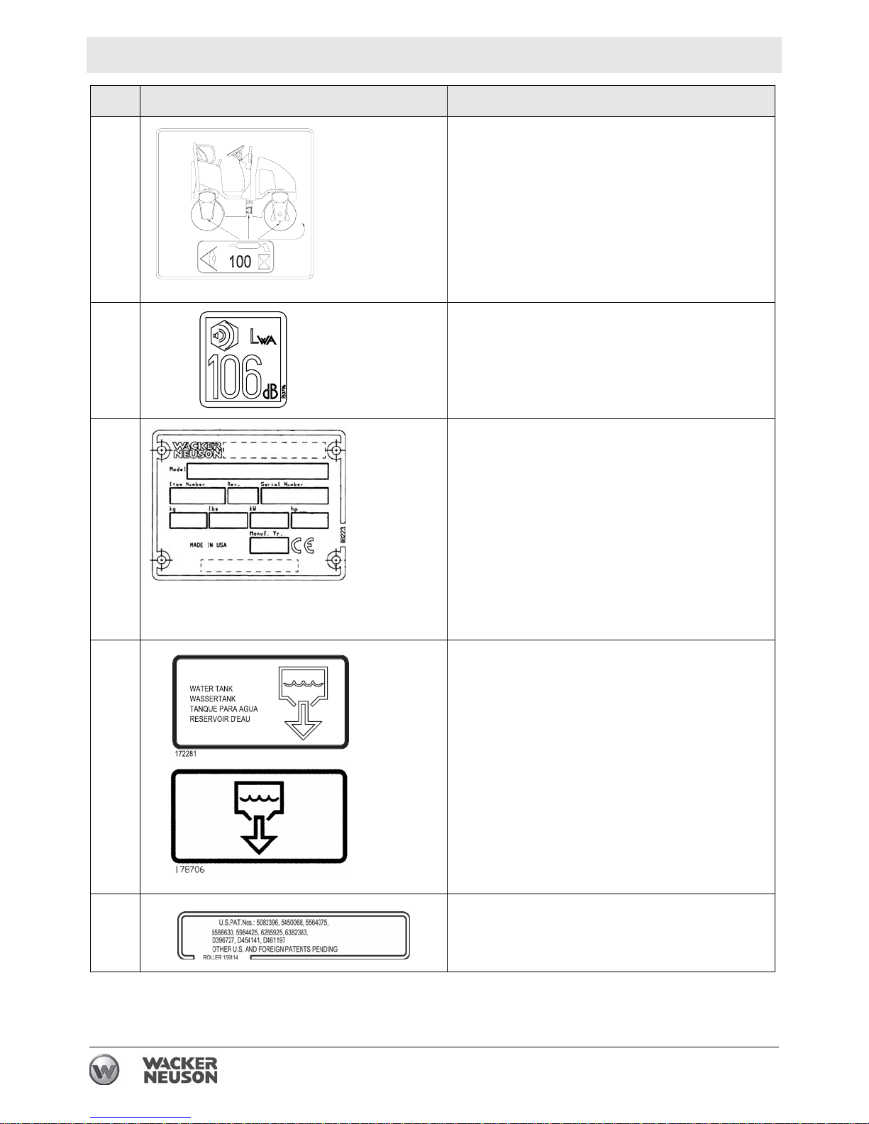
2.3 Informational Labels
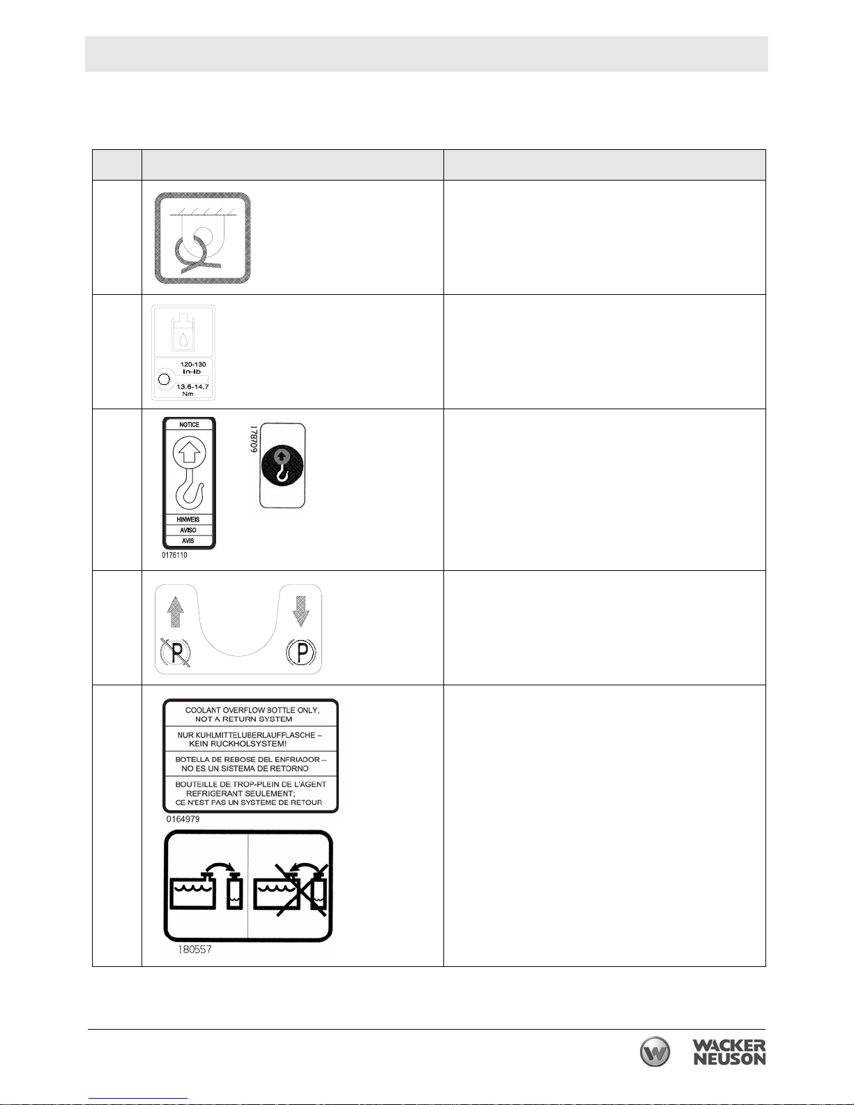
Ref. Label Meaning
C
J
Q
Tie-down point.
I
Hydraulic oil reservoir fill tube.
Torque nuts to 13.6-14.7 Nm (120-130 in.lbs.)
maximum.
NOTICE
Lifting point.
Parking brake is disengaged.
S
Parking brake is engaged.
Coolant overflow bottle only, not a return system.
wc_si000400gb.fm 25
Page 26
Labels RD 16
Ref. Label Meaning
U
X
Y
Grease points: Inspect and lubricate every 100
hours of operation.
Guaranteed sound power level in dB(A).
A nameplate listing the model number, item number, revision number, and serial number is
attached to each unit. Please record the information found on this plate so it will be available
should the nameplate become lost or dam ag ed .
When ordering parts or requesting service information, you will always be asked to specify the
model number, item number, revision number,
and serial number of the unit.
EE
FF
Water tank fill.
This machine may be covered by one or more
patents.
26 wc_si000400gb.fm
Page 27

RD 16 Labels
Ref. Label Meaning
GG
Low sulfur fuel or ultra low sulfur fuel only.
wc_si000400gb.fm 27
Page 28

Operation RD 16
3 Operation
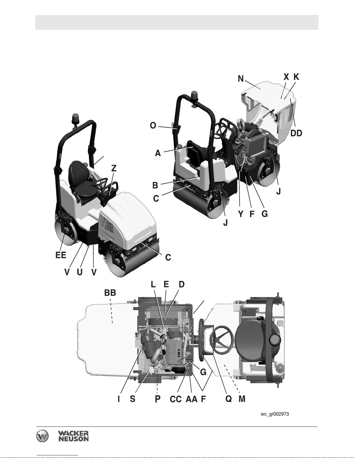
3.1 Operation and Service Locations
9
34
29
30
28
20
13
38
16
21
45
28
7
38
28
37 19
11 12
8
3
31
10
24
30
15
33
22
7
27
2
23
41
39
40
17
28
37
11
33
14
36
1
18
37
25
5
6
42
4
32
35
37
wc_gr002947
28 wc_tx001075gb.fm
33
Page 29

RD 16 Operation
See Graphic: wc_gr002947
Ref. Description Ref. Description
1 Air cleaner 22 Water tank fill cap
2 Articulated joint 23 Lockarm
3 Hand holds 24 Operator’s platform
4 Control panel 25 Engine oil filter
5 Dipstick 27 Rear drum
6 Drain hose—hydraulic tank 28 Scraper bar (4 places)
7 Drive motor (2) 29 Sightglass—hydraulic tank
8 Drive pump 30 Sprinkler tube (2)
9 Engine hood 31 Steering wheel
10 Vibration control button 32 Steering cylinder (under floor panel)
11 Exciter motor (2) 33 Tiedown (2 places)
12 Exciter/Steering pump 34 Rotating beacon
13 Hydraulic filter—return line 35 Battery (under floor panel)
14 Hydraulic strainer—suction line 36 Hydraulic suction line
15 Forward/Reverse control 37 Grease fitting—exciter (4 places)
16 Front drum 38 Lifting eye (4 places)
17 Fuel tank fill cap 39 ROPS
18 Fuel filter 40 Adjustable seat with seat belt
19 Grease fittings—articulated joint (4
41 Water drain
places)
20 Hydraulic tank fill port 42 Parking brake button
21 Hydraulic manifold block 45 Auxiliary battery positive terminal
wc_tx001075gb.fm 29
Page 30
Operation RD 16
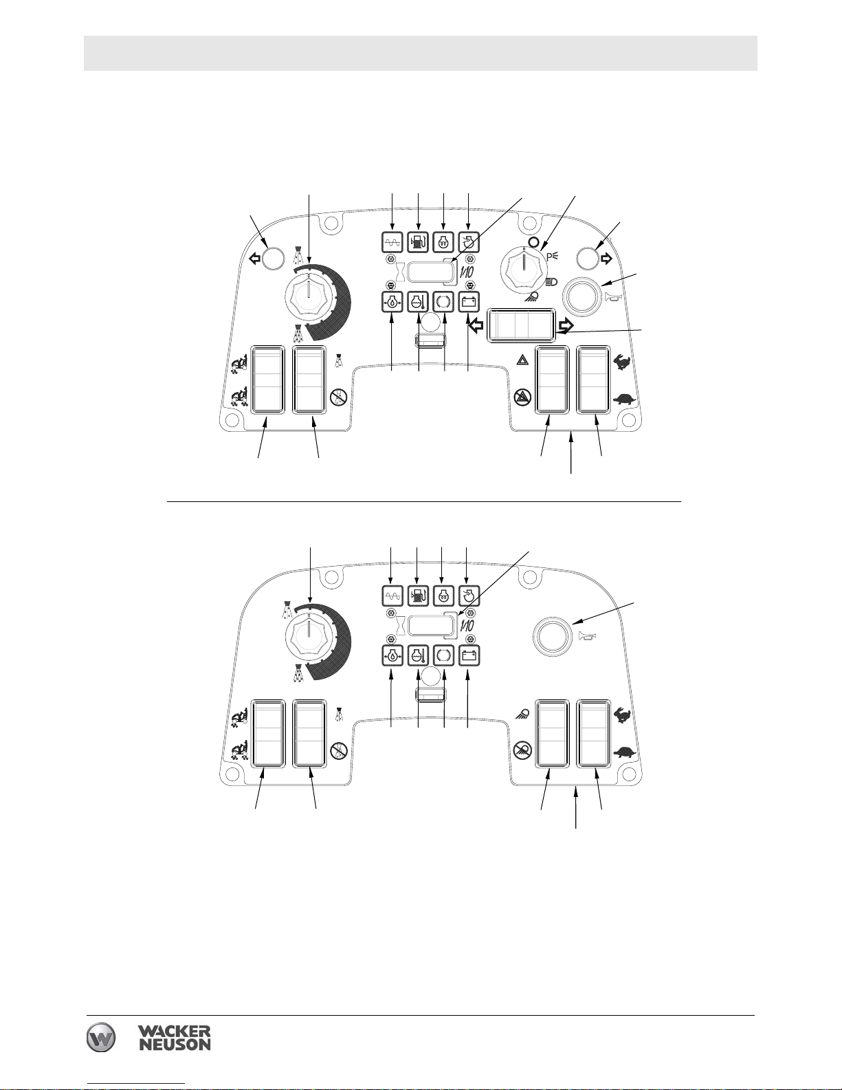
3.2 Control Panel
RD 16 IRH
5658 57 47 52
62
53
50
53
64
46
RD 16-90
RD 16-100
63
61
62
49
48
5658 57
50
49
48
59
59
60
60
51
47
54
55
64
63
61
51
54
55
wc_gr004113
30 wc_tx001075gb.fm
Page 31

RD 16 Operation
See Graphic: wc_gr004113
Ref. Description Ref. Description
46 Turn signal switch—LEFT and RIGHT
56 Low fuel indicator
(RD 16IRH only)
47 Hour meter 57 Air filter indicator
48 Engine coolant temperature indicator 58 Glow plug indicator
49 Low oil pressure indicator 59 Parking brake ON indicator
50 Vibration ON indicator 60 Battery indicator
51 Hazard lights switch—ON and OFF 61 Water spray switch—ON and OFF
52 Lights switch—multi-position
62 Water spray dial
(RD 16IRH only)
53 Turn signal indicator
(RD 16IRH only)
63 Vibration switch —BOTH DRUMS
and FRONT DRUM ONLY
54 Throttle switch—HIGH and LOW 64 Horn
55 Ignition switch - ---
wc_tx001075gb.fm 31
Page 32

Operation RD 16
3.3 Roll Over Protection Structure (ROPS)
The machine is equipped with a Roll Over Protection Structure
(ROPS). The machine is normally delivered to the customer with the
ROPS folded forward to facilitate transport.
Do not use the machine without the ROPS in place. The ROPS is
designed to protect the operator in a rollover accident.
WARNING
Before using the machine, position the ROPS in the fully upright
position as follows:
3.3.1 Support the ROPS using a crane and suitable rigging capable of
supporting 43 kg (95 lbs.).
NOTICE: Do not use the ROPS to lift the machine.
3.3.2 Remove the shipping strap from both sides of the frame. Save the
washers.
3.3.3 Loosen the bottom mounting bolt on both sides.
3.3.4 Rotate the ROPS into the upright position.
3.3.5 Secure the ROPS to the frame using the saved washers and the
supplied bolts. Torque hardware to 106 Nm (78 ft.lbs.).
Each month, check the torque on all of the screws holding the ROPS
in place. Check that the ROPS frame is not rusty, cracked, broken, or
damaged in any way.
Change the seat belts every 3 years, or any time they have been
subjected to accident-level loads.
If the ROPS has been removed from the machine, it must be
reinstalled before the machine is used. When reinstalling the ROPS,
use the original nuts and bolts and tighten the bolts to the specified
torques.
Do not weld or drill into the ROPS. Drilling or welding on the ROPS will
nullify the ROPS certification.
WARNING
Personal injury hazard. The ROPS is not a handhold for passengers. Passengers
can be seriously injured or killed from falls, tip-overs, or roll-over incidents.
f Do not allow anyone to ride on any part of the machine.
32 wc_tx001075gb.fm
Page 33

RD 16 Operation
3.4 Foldable Roll Over Protection Structure (ROPS) (if equipped)
See Graphic: wc_gr002957
The machine is equipped with a Roll Over Protection Structure
(ROPS). The machine is normally delivered to the customer with the
ROPS folded forward to facilitate transport.
Do not use the machine without the ROPS in place. The ROPS is
designed to protect the operator in a rollover accident.
WARNING
Before using the machine, position the ROPS in the fully upright
position as follows:
3.4.1 Support the upper mass ROPS using a crane and suitable rigging
capable of supporting 19 kg (42 lbs.).
NOTICE: Do not use the ROPS to lift the machine.
3.4.2 Remove the safety pin (a) and pull out the locking pin (b). Do so on
both sides.
3.4.3 Lift the ROPS into the upright position.
3.4.4 Insert the locking pins and secure them with the safety pins.
Be aware of pinch points when lowering and raising the ROPS.
WARNING
To lower the ROPS:
3.4.5 Support the upper mass of the ROPS using a crane and suitable
rigging capable of supporting 19 kg (42 lbs.).
3.4.6 Remove the safety pin (a) and pull out the locking pin (b). Do so on
both sides.
3.4.7 Gently lower the upper mass.
Note: When lowering ROPS, do not allow the upper frame to fall into
the lower position. Allowing the upper mass to slam will weaken the
ROPS system and ultimately compromise its integrity and protection.
3.4.8 Insert the pins in the ROPS in the lower hole setting through the upper
mass to secure it for transport.
Each month, check the torque on all of the screws holding the ROPS
in place. Check that the ROPS frame is not rusty, cracked, broken, or
damaged in any way.
Keep the ROPS in the extended (upright) position when using the
roller, and always use the seat belts provided.
Change the seat belts every 3 years, or any time they have been
subjected to accident-level loads.
wc_tx001075gb.fm 33
Page 34

Operation RD 16
If the ROPS has been removed from the machine, it must be
reinstalled before the machine is used. When reinstalling the ROPS,
use the original nuts and bolts and tighten the bolts to the specified
torques.
Do not weld or drill into the ROPS. Drilling or welding on the ROPS will
nullify the ROPS certification.
34
b
a
wc_gr002957
WARNING
Personal injury hazard. The ROPS is not a handhold for passengers. Passengers
can be seriously injured or killed from falls, tip-overs, or roll-over incidents.
f Do not allow anyone to ride on any part of the machine.
34 wc_tx001075gb.fm
Page 35

RD 16 Operation
3.5 Rotating Beacon (if equipped)
See Graphic: wc_gr002957
The rotating beacon (34) powers up when the ignition switch is turned
to the ON position. The beacon illuminates and rotates when powered
up.
To install the beacon:
3.5.1 Slide the rotating beacon onto the light staff.
3.5.2 Tighten the wing nut on the base of the light.
3.6 Backup Alarm (if equipped)
The backup alarm is located on the rear of the machine.
Start the engine and move the forward/reverse control to the reverse
position. The backup alarm should sound immediately. The backup
alarm will continue to sound until the forward/reverse control is moved
to the neutral position or to the forward position.
If the backup alarm does not sound, make the necessary repairs
before using the roller.
wc_tx001075gb.fm 35
Page 36

Operation RD 16
3.7 Lighting Equipment (if equipped)
See Graphic: wc_gr004115
When working in the dark or in bad visibility, use all the lights available.
Replace broken bulbs immediately. Only replace bulbs when the
machine is turned off. Remember that your safety and the safety of
WARNING
others depends on your care and attention when operating this
machine.
Parking lights (A)
On the RD 16 IRH only, this switch position turns on the parking lights.
Lights on (B)
On the RD 16 IRH, this switch position turns on the rear work lights.
On the RD 16, this switch position turns on the front and rear lights.
Front road lights (C)
On the RD 16 IRH only, this switch position turns on the front lights.
Lights off (D)
This switch position turns off all the lights.
B
D
51
52
wc_gr004115
D
A
C
B
36 wc_tx001075gb.fm
Page 37

RD 16 Operation
3.8 Seat Belt
See Graphic: wc_gr002238
Pull seat belt (c) out of the retractor in a continuous motion.
Fasten seat belt catch (b) into buckle (a). Make sure that the seat belt
is placed low across the lap of the operator.
The retractor will adjust the belt length and the retractor will lock in
place.
Push the release button (d) on the buckle in order to release the seat
belt. The seat belt will automatically retract into the retractor.
Replace the seat belt every three years.
c
d
a
b
wc_gr002238
wc_tx001075gb.fm 37
Page 38

Operation RD 16
3.9 Operator Presence System
See Graphic: wc_gr002962
The machine is equipped with an “operator presence system”. This
system is part of the driver's seat and senses the weight of an operator
in the seat. If the operator is not sitting in the driver's seat, the roller will
NOT drive. If the operator leaves the driver’s seat, the brakes will
activate. When the operator sits down again, the forward/reverse
control must be placed in the neutral position before the roller can be
driven or the vibration can be started.
Note: A one-half second delay keeps the system from tripping when
the roller passes over a bump.
If the roller is supplied with an adjustable seat, it can be adjusted as
follows:
• Knob (a) for adjusting the seat tension to the driver's weight.
• Lever (b) for adjusting the distance from the seat to the driving
controls.
WARNING
Note: Do not change position of the driver’s seat while the machine is
moving. The “OPERATOR PRESENCE” safety device will prevent all
machine movements if an operator is not seated.
Always wear the seat belt provided when operating the roller.
a
b
wc_gr002962
38 wc_tx001075gb.fm
Page 39

RD 16 Operation
3.10 Scraper Bars
See Graphic: wc_gr003447
Scraper bars, located in front of and behind each drum, are used to
prevent dirt and asphalt from sticking to and accumulating on the drum
surface.
These scrapers are spring loaded. They may be set in the travel
position (a) or the scraping position (b) by flipping the bar up or down.
a
b
b
wc_gr003447
a
wc_tx001075gb.fm 39
Page 40

Operation RD 16
3.11 Anti-Vandalism Protection and Machine Access
Parts of the machine which may be subject to theft or vandalism when
the vehicle is parked unattended can be padlocked to prevent
unauthorized access or use.
Lockable parts are:
• Engine cover.
• Control panel.
• Fuel cap.
To lock the engine cover, close the cover and attach a padlock to the
fastener.
The control panel cover is stored on the front of the control column
during operation and service. To lock the control panel, place the cover
on the panel and attach a padlock to the fastener.
Note: Padlocks are not supplied with the machine.
To lock the fuel cap, close cap completely and push in the locking tab
on the cap and attach padlock.
40 wc_tx001075gb.fm
Page 41

RD 16 Operation
3.12 Articulation Joint Lockarm
See Graphic: wc_gr002956
A lockarm (23), located below the articulated joint, is provided to
secure the front and rear halves of the roller together. Once secured,
the lockarm prevents the two halves from swinging together.
To avoid being pinched by machine halves, set the lockarm before
lifting the machine for transport or repairs!
WARNING
To set lockarm, release it from its holder and swing it out from its stored
position. Place the forward end of the arm into the hole provided in the
front frame of the machine. Secure it in this position using the large
hairpin cotter provided.
ALWAYS disengage and stow locking bar for the articulated steering
joint before operating machine. The machine cannot be steered when
WARNING
the locking bar is engaged.
23
wc_tx001075gb.fm 41
wc_gr002956
Page 42

Operation RD 16
2
3.13 Machine Stability
WA R NIN G
Crushing hazards. Certain job site conditions or operating practices may adversely
affect machine stability.
f
Follow the instructions below to reduce the risk of tipping or falling incidents.
Surface conditions
Pay attention to changing surface conditions while operating the
machine. Adjust speed and travel direction as necessary to maintain
safe operation.
• Machine stability and traction may be severely reduced when
operating on uneven or rough terrain, rocky soils, or wet or
loosely packed surface material.
• The machine may suddenly tip, sink, or fall when moved onto surfaces that have been newly filled with earth.
Steering angle
An articulated roller is more likely to tip when moving off an elevated
surface if the machine is turned away from the edge.
• As shown in the illustration on the right, always turn the machine
toward the edge when moving off an elevated surface.
Travel speed
A fast moving machine is more likely to tip or fall over while making
turns or changing direction.
wc_gr00704
• Reduce travel speed before turning the machine.
Drum overhang
The machine can tip suddenly if more than half of the drum width
extends beyond the edge of the elevated surface.
42 wc_tx001075gb.fm
Page 43

RD 16 Operation
• Reduce travel speed and watch the drum position carefully when
operating along the edge of an elevated surface.
• Keep as much of the drum on the elevated surface as possible.
Vibrating on a compacted surface
Activating the vibratory system on a fully compacted surface may
cause the drums to rebound and momentarily lose contact with the
ground. If this occurs while the machine is on an incline, the machine
may slide.
• If the drums rebound on the compacted surface, reduce vibration
speed or stop vibration entirely.
wc_tx001075gb.fm 43
Page 44

Operation RD 16
3.14 Operation on Slopes
See Graphic: wc_gr003448
When operating on slopes or hills special care must be taken to reduce
the risk of personal injury or damage to the equipment. Always operate
the machine up and down hills rather than from side to side. For safe
operation and for protection of the engine, continuous duty use should
be restricted to front/rear slopes of 17° (30% grade) or less.
NEVER operate machine on side slopes. The machine may roll over,
even on stable ground. Always operate the machine parallel to the
WARNING
slope; never perpendicular.
3.15 Recommended Fuel
The engine requires No. 2 diesel fuel. Use only fresh, clean fuel. Fuel
containing water or dirt will damage the fuel system. Consult the
engine owner’s manual for complete fuel specifications.
17˚
30%
wc_gr003448
44 wc_tx001075gb.fm
Page 45

RD 16 Operation
3.16 Position of the Operator
Safe and efficient use of this machine is the operator’s responsibility.
Full control of the machine is not possible unless the operator
maintains the proper working position at all times.
While operating this machine, the operator must:
• be seated in the operator’s seat facing forward
• wear the seat belt, properly adjusted and latched
• have both feet on the control deck
• have one hand on the steering wheel at all times
• have the other hand free to operate the controls as needed
3.17 Preparing the Machine for First Use
Preparing for first use
To prepare your machine for first use:
3.17.1 Make sure all loose packaging materials have been removed from the
machine.
3.17.2 Check the machine and its components for damage. If there is visible
damage, do not operate the machine! Contact your Wacker Neuson
dealer immediately for assistance.
3.17.3 Take inventory of all items included with the machine and verify that
all loose components and fasteners are accounted for.
3.17.4 Attach component parts not already attached.
3.17.5 Add fluids as needed and applicable, including fuel, engine oil, and
battery acid.
3.17.6 Move the machine to its operating location.
wc_tx001075gb.fm 45
Page 46

Operation RD 16
Notes
46 wc_tx001075gb.fm
Page 47

RD 16 Operation
3.18 Before Starting
Before starting the machine check the following:
• Engine oil level
• Engine coolant level
• Hydraulic fluid level
• Condition of fuel lines
• Condition of air cleaner
• Operation of the brake system
• Fuel level
• Water level
• Condition of safety belt
• Scraper bars—clean and properly adjusted
Note: All fluid levels should be checked with the machine on a level
surface.
WARNING
Ensure that regular maintenance has been carried out.
Ensure that the driver's platform is clean.
Always use the steps and handrails when climbing on and off the
machine.
Always wear the seat belt provided when operating the roller.
wc_tx001075gb.fm 47
Page 48

Operation RD 16
3.19 Starting
See Graphic: wc_gr002952
Exhaust gases are toxic. Do not start the engine in enclosed spaces.
WARNING
3.19.1 Sit down in the operator’s seat and fasten the seat belt.
3.19.2 Set the forward/reverse control (15) in the NEUTRAL position.
3.19.3 Press the parking brake button in (42) to set parking brake.
Note: The roller will not start unless the forward/reverse control is in
the NEUTRAL position.
3.19.4 Turn the starting switch (55) to the ON position. The glow plug indicator
(58) will illuminate signifying the glow plugs are on. The glow plug
indicator will stay on; approximately 30 seconds at 0°C (32°F). Do not
start the engine until the glow plug indicator light goes out.
3.19.5 Turn the starting switch (55) to the START position.
NOTICE: Do not crank the engine starter for more than 15 seconds at
one time. Longer cranking cycles could lead to starter damage.
Note: The starting switch has an anti-restart feature. If the engine does
not start, the switch will need to be turned to the OFF position before it
will allow the engine to be cranked again.
3.19.6 Allow the engine to warm up for a few minutes before operating the
roller.
3.19.7 Disengage the parking brake by pulling the parking brake button out.
3.19.8 Quickly press and release the upper half of the throttle switch (54) to
bring the engine to high throttle.
Prolonged exposure to high noise levels can damage your hearing.
Wear appropriate hearing protection while operating the roller.
WARNING
48 wc_tx001075gb.fm
Page 49

RD 16 Operation
wc_tx001075gb.fm 49
Page 50

Operation RD 16
3.20 Stopping/Parking
See Graphic: wc_gr002954
3.20.1 Stop the machine on a flat surface with a suitable load bearing
capacity.
3.20.2 Turn the vibration off by pressing the vibration control button (10) on
the forward/reverse lever (15).
3.20.3 Press the water spray switch (61) to the OFF position.
3.20.4 Set the forward/reverse control (15) to the NEUTRAL position.
3.20.5 Return the engine throttle to idle by pressing the lower half of the
throttle switch (54) and allow the engine to cool down.
3.20.6 Press the parking brake button (42) to set the parking brake. Always
set the parking brake before leaving the machine.
If the vehicle constitutes a hazard or obstacle to traffic when parked, it
should be marked with signs, lights, and other warnings.
WARNING
3.20.7 Stop the engine by turning the starting switch to the OFF position (55).
If the machine must be parked on a sloping surface, chock the drums
with wedges to prevent any vehicle movement.
Note: On the RD 16, the parking brake is automatically applied within
the drive motors. The brakes are applied under the following
conditions:
• engine is not running
• engine is running and the operator is not on the seat
• parking brake button is pushed
50 wc_tx001075gb.fm
Page 51

RD 16 Operation
3.21 Parking Brake Button
See Graphic: wc_gr002954
To hold the machine in a stopped position (parked), there is a
mechanical parking brake on each drum drive motor. The mechanical
parking brakes are spring-activated and hydraulically released (SAHR)
type brakes. The brakes are applied when the engine is switched off or
the operator leaves the seat.
When pushed in, the parking brake button (42) stops all travel (either
forward or reverse) and applies the brake. The brakes can be released
by pulling the parking brake button out.
The forward/reverse control (15) must be in the NEUTRAL position to
allow the release of the brakes. If the forward/reverse control is not in
the NEUTRAL position when the parking brake is released, the brakes
will not be released.
NOTICE: Under normal operating conditions, do not use the parking
brakes when the machine is moving. The parking brakes should only
be used in cases of emergency when the machine is moving, e.g.,
following failure of the main hydraulic braking system (moving the
forward/reverse control to the NEUTRAL position) or in a runaway
condition traveling down a slope. Using the parking brake while the
machine is moving may cause damage to the drive motors.
wc_tx001075gb.fm 51
Page 52

Operation RD 16
3.22 Direction and Speed
See Graphic: wc_gr002954
The forward/reverse control (15) controls both the direction and speed
of the roller. Use the control lever, rather than the throttle, to control the
speed of the machine while compacting.
Speed is controlled by the amount the lever is moved in the direction
of travel—forward or reverse.
During operation, to run the machine at full throttle, press and release
the upper half of the throttle switch (HIGH) (54). This ensures
maximum travel speeds and will produce the best compaction results.
Operating the machine at slower engine speeds will reduce
compaction, slow down machine functions, and damage hydraulic
components.
52 wc_tx001075gb.fm
Page 53

RD 16 Operation
3.23 Transmission
See Graphic: wc_gr002954
Both roller drums are fitted with hydraulic motors which are driven by
an infinitely variable displacement pump and hydrostatic transmission.
Forward and reverse travel are selected using a forward/reverse
control (15) located next to the driver’s seat. In order to comply with
safety standards, the machine has a device which only enables
starting of the engine when the forward/reverse control is in the
NEUTRAL position.
Forward/reverse control
Shift the forward/reverse control (15) into FORWARD (F) or REVERSE
(R) according to the direction of travel desired. The further forward or
reverse the control is positioned, the faster the roller will travel.
Road speed is the same in both FORWARD and REVERSE. If you
wish to change direction of travel from FORWARD to REVERSE or
vice versa, move the control to the NEUTRAL position (N), allow the
vehicle to come to a complete stop, then move the control in the
direction desired.
During operation run the machine at high throttle. Quickly press and
release the upper half of the throttle switch (54) to bring the engine to
high throttle.
When negotiating gentle slopes, keep the engine at high throttle and
the forward/reverse control at the minimum speed position.
NOTICE: This vehicle has a hydrostatic transmission which means
that the forward/reverse control can also be used as an engine brake.
Shifting the control to the NEUTRAL position stops the machine travel.
NOTICE: Never drive the machine at low idle speed. Driving the
machine at low idle speed can damage the drive pump.
wc_tx001075gb.fm 53
Page 54

Operation RD 16
3.24 Vibration
See Graphic: wc_gr005893
The vibration is turned ON or OFF by a push button (10) located on the
forward/reverse control (15). Press the button to turn vibration ON;
press it again to turn it OFF. The vibration ON indicator (50) will light
when vibration is on. The vibration can be turned on while operating in
either forward or reverse and will remain on until it is turned off.
Select either the front drum vibration or dual drum vibration by pressing
the vibration switch (63) on the control panel.
CAUTION: If the machine has been turned off with the vibration on, the
vibration will come on as soon as the machine is restarted. Therefore,
for easier starting and to keep the surface finish smooth, be ready to
switch vibration off should it come on while cranking the engine.
Note: The vibration will remain on even when the forward/reverse
control (15) is in NEUTRAL. When operating on asphalt and in order
to keep the surface finish smooth, turn the vibration off before stopping
the roller.
50
63
10
15
wc_gr005893
N
F
R
54 wc_tx001075gb.fm
Page 55

RD 16 Operation
3.25 Water Spray System
See Graphic: wc_gr003638, wc_gr002947
Water from the tank is fed to the spray bars by an electric pump. The
flow of the water is controlled by a switch and a rotary dial.
Press the upper half of the water spray switch (61) to turn the water
pump on. Turn the water spray dial (62) clockwise to increase the
spray frequency. Turn the water spray dial counter-clockwise to
decrease the spray frequency. Press the lower half of the water spray
switch (61) to turn the water pump off.
Only use clean water. Dirty water, even when filtered, will rapidly clog
the tubes of the spraying equipment.
During winter, or when temperatures drop to below 0°C (32°F), drain
the water tank and spraying equipment. Run the water pump to
remove excess water from the system. Drain the water through the
water drain plug (41) located near the bottom of the rear frame,
through the sprayer end plugs, and the water filter. Freezing water may
cause broken hoses, filters and water pumps and may deform the
water tank.
62
61
wc_gr003638
wc_tx001075gb.fm 55
Page 56

Operation RD 16
3.26 Emergency Shutdown Procedure
If a breakdown/accident occurs while the machine is operating, follow
the procedure below.
3.26.1 Stop the engine.
3.26.2 Allow the engine and exhaust system to cool.
3.26.3 Using appropriate equipment, return the machine to an upright
position if tipped over.
3.26.4 Contact rental yard or machine owner .
56 wc_tx001075gb.fm
Page 57

RD 16 Operation
3.27 Battery Disconnect
This machine is equipped with a battery disconnect switch located in
the engine compartment.
To disconnect and isolate the electrical system from the battery,
remove the wing-nut and remove the cable from the stud.
To reconnect the battery, place the battery cable on the stud and
secure with the wing-nut.
Isolate the battery before performing any maintenance operations on
electrical equipment.
WARNING
3.28 Auxiliary Battery Positive Terminal
This machine is equipped with an auxiliary battery positive terminal
(45) located above the battery disconnect stud.
CAUTION
CAUTION! Electric shock hazard. Never touch this terminal and a
metal portion of the machine simultaneously.
45
wc_gr004357
wc_tx001075gb.fm 57
Page 58

Operation RD 16
3.29 Panel Indicator Lights
RD 16 IRH
5658 57
50
53
53
46
RD 16-90
RD 16-100
49
48
5658 57
50
49
48
59
59
60
60
51
55
55
wc_gr004117
58 wc_tx001075gb.fm
Page 59

RD 16 Operation
See Graphic: wc_gr004117
Engine coolant temperature indicator (48)
This warning light illuminates to indicate that the engine has
overheated and the engine will shut down.
NOTICE: Trace the cause of overheating and rectify the situation
before operating the machine.
Low oil pressure indicator (49)
This warning light illuminates when the ignition switch (55) is in the on
position and the engine is not running; it goes out once the engine has
started.
If the light illuminates when the engine is running, it indicates that the
oil pressure is low and the engine will shut down.
Possible causes for the light to illuminate:
• Oil level is too low.
• Incorrect oil viscosity for the time of year.
• Fault in the oil circuit.
Do not operate the machine if the light is illuminated.
Vibration ON indicator (50)
This indicator light illuminates to indicate that the vibration is on.
Low fuel indicator (56)
This indicator light illuminates to indicate that the fuel level is low.
Air filter indicator (57)
This indicator light illuminates to indicate that the air cleaner needs to
be changed.
Glow plug indicator (58)
This indicator light illuminates to indicate that the glow plugs are on.
Parking brake button indicator (59)
This indicator light illuminates to indicate that the parking brake button
is activated.
Battery indicator (60)
This indicator light illuminates when the battery is not charging.
wc_tx001075gb.fm 59
Page 60

Operation RD 16
3.30 Turn Signal/Hazard Lights (if equipped)
See Graphic: wc_gr004117
These switches are only available on machines equipped with the
optional roading light package.
Turn Signal Switch
Press the turn signal switch (46) to activate the desired turn signal. The
signal lights (53) will flash when the turn signal switch is operating.
Return the turn signal switch to the middle position to deactivate the
turn signal.
Hazard Lights
Press the hazard light switch (51) to the ON position to activate the
hazard lights. The turn signal lights (53) will flash to indicate function.
Press the hazard light switch to the OFF position to deactivate the
hazard lights.
60 wc_tx001075gb.fm
Page 61

RD 16 Operation
Notes
wc_tx001075gb.fm 61
Page 62

Maintenance RD 16
4 Maintenance
4.1 Engine Maintenance Schedule
The table below lists basic engine maintenance. Tasks designated
with check marks may be performed by the operator. Tasks
designated with square bullet points require special training and
equipment.
Refer to the engine manufacturer’s Operation Manual for additional
information.
Lombardini Engine
Check engine oil and coolant level. Fill to
correct level.
Replace air filter if indicator light is on.
Clean engine head and cylinder fins.
Change oil in engine crankcase.
Replace engine oil filter.
Replace fuel filter cartridge.
Clean injectors and check injector pres-
sure.
Check valve clearance.
Daily
before
starting
3
3
Every
100
hrs.
3
3
Every
300
hrs.
Every
500
hrs.
62 wc_tx001076gb.fm
Page 63

RD 16 Maintenance
4.2 Roller Maintenance Schedule
The table below lists basic machine maintenance. Tasks designated
with check marks may be performed by the operator. Tasks
designated with square bullet points require special training and
equipment.
Check external hardware.
Check level of hydraulic fluid.
Grease articulated joint.
Grease rear drum drive bearings.
Grease exciter bearings.
Check scraper bars.
Check battery.
Grease steering cylinder ends.
Change hydraulic system return line filter.
Clean battery terminals.
Change hydraulic oil.
Daily Every
100
hrs.
3
3
3
Every
600
hrs.
3
Every
1200
hrs.
Daily before starting:
• Check operation of parking brake, making sure it engages.
• Check for leaks around hydraulic hoses and connections.
• Check for leaks around fuel lines and connections.
• Clean engine exterior, cooling fins, and blower housing.
• Check electrical wiring and connections.
• Check operation of NEUTRAL safety switch.
• Inspect seat belt.
New Machines:
• Change engine oil per engine schedule.
• Replace hydraulic system return line filter after first month or 100 hours of
operation.
All machines:
• Increase air cleaner/filter inspections and cleaning under dusty conditions.
Notes
wc_tx001076gb.fm 63
Page 64

Maintenance RD 16
4.3 Safety-Related Spare Parts
Overview
This machine is equipped with several features to enhance operator
safety. These include the ROPS and the seat belt. For your
convenience, we have provided the following diagrams and lists of
replacement parts for these safety-related features.
For a complete list of spare parts for this machine, contact your
Wacker Neuson dealer or visit www.wackerneuson.com.
ROPS diagram
wc_gr007046
64 wc_tx001076gb.fm
Page 65

RD 16 Maintenance
ROPS parts list
Ref. Part No. Qty. Description Measurement
224 0163264 1 ROPS frame
533 0162980 2 Red reflector
550 0163627 1 Bracket
551 0163224 1 Mount
552 0162959 1 Beacon group option
594 0162345 1 Light bulb
595 0162341 1 Retaining clip
675 0020378 8 Hex head screw
699 0163948 2 Hexagonal flange head screw
733 0031565 8 Lock washer
1090 0172013 2 Pivot screw
1091 0172014 2 Pivot nut
1092 0172015 2 Washer
1093 0172016 2 Pin
1094 0172017 2 Cable
1095 0172018 2 Shockmount
1096 0172019 2 Nut
1097 0172020 1 Label
wc_tx001076gb.fm 65
Page 66

Maintenance RD 16
Seat assembly diagram
wc_gr007047
66 wc_tx001076gb.fm
Page 67

RD 16 Maintenance
Seat assembly parts list
Ref. Part No. Qty. Description
1 0163274 1 Plate
2 0163324 1 Adjustable seat
3 0164779 1 Seat switch
4 0083220 1 Holder
5 0030066 4 Lock nut M8
6 0013002 2 Hex head screw M12 x 25
7 0010620 2 Flat washer B13
8 0010366 2 Lock nut M12
9 0164846 1 Hardware set
Measurement
and torque
34 Nm / 25 ft.lbs
86 Nm / 63 ft.lbs
83 Nm / 61 ft.lbs
wc_tx001076gb.fm 67
Page 68

Maintenance RD 16
4.4 Maintaining the Seat and the Seat Belt
Background
In order for the seat and seat belt to operate safely and properly over
a long period of time, periodic maintenance and occasional repairs
are necessary. Poorly maintained equipment can become a safety
hazard!
Maintaining the seat and seat belt
• Keep the seat clean. Dirt, dust, or harsh chemicals can damage
the upholstery. Repair holes or tears immediately.
• If necessary, clean the seat belt with a mild soap solution. Do not
use chemical cleaners, as they will damage the fabric.
• Periodically test the operation of the seat tension knob and the
front-to-back lever. Repair or replace worn or malfunctioning
components.
• If the seat does not move smoothly during adjustment, apply a
small amount of standard bearing grease (such as Shell Alvania®
RL2 or equivalent) to the rails.
68 wc_tx001076gb.fm
Page 69

RD 16 Maintenance
4.5 Cleaning the Spray Bars
Background
Clogged or dirty spray bars can prevent water from spraying onto the
drums. If water spray is noticeably reduced or absent even though
there is water in the tank, then clean the spray bars.
Procedure
Follow the procedure below to clean the spray bars.
4.5.1 Locate the plugs (a) at the ends of each spray bar (b). Unscrew and
remove the plugs.
b
a
a
a
c
a
a
a
wc_gr007077
4.5.2 Flush the inside of the spray bar with clean water.
4.5.3 Reinstall one of the plugs, and again flush the inside of the spray bar
with clean water . Check for free flow of water through each spray hole
(c).
4.5.4 If any of the spray holes are blocked, use a small pointed object (i.e. a
stiff piece of wire) to remove the blockage.
4.5.5 Reinstall the second plug when all spray holes are clean.
wc_tx001076gb.fm 69
Page 70

Maintenance RD 16
4.6 Rear Frame Access
See Graphic: wc_gr004333
The operator’s platform is mounted on hinges and can be lifted open
to provide access to the water pump, the water filter, the battery, the
hydraulic hoses, and the fuel tank. The platform has lifting cylinders
that hold the platform in the open position.
NOTICE: The lifting cylinders do not have enough force to lift and hold
the platform in the open position when the tank is filled with water. If
there is water in the water tank, drain all water before lifting the
platform.
To open:
4.6.1 Drain water from the water tank. See section Water Spray System.
4.6.2 Remove the two bolts (a) locking the operator’s platform to each side
of the rear frame.
4.6.3 Slowly lift up on the steering column (b).
Note: Lifting the operator’s platform too far can damage the lifting
cylinders and other components.
NOTICE: Do not disconnect the lifting cylinders to open the platform
further. Fuel may leak out of the fuel cap.
To close:
4.6.4 Push down on the platform to return to the operating position.
4.6.5 Replace the two bolts (a) locking the operator’s platform to each side
of the rear frame.
70 wc_tx001076gb.fm
Page 71

RD 16 Maintenance
4.7 Fuel Filter
See Graphic: wc_gr002999
4.7.1 Change the fuel filter (a) every 300 hours of operation. Remove the
filter (a) from the filter head (c).
4.7.2 Install the new filter. If necessary, prime the fuel lines. See section RD
16 Priming the Fuel System.
Gasoline is extremely flammable! Turn the engine off and allow the
engine to cool before replacing the fuel filter.
WARNING
c
b
a
4.8 Priming the Fuel System
See Graphic: wc_gr002999
If the fuel tank has been run completely dry or drained for service, it
may be necessary to manually prime the fuel system.
To prime the fuel system:
4.8.1 Turn the ignition switch to the ON position (60). This will open the fuel
valve.
4.8.2 Pump the lever on the fuel pump (b) until there is an increase in
pumping effort.
wc_gr002999
wc_tx001076gb.fm 71
Page 72

Maintenance RD 16
4.9 Battery
See Graphic: wc_gr002565
Before servicing this machine, make sure the ingnition switch is in the
OFF position and that the battery is disconnected. Attach a “DO NOT
START” sign to the machine. This will notify other personnel that the
unit is being serviced and will reduce the chance of someone
inadvertently trying to start the unit.
Explosion hazard. Batteries can emit explosive hydrogen gas. Keep all
sparks and flames away from the battery. Do not short-circuit battery
WARNING
WARNING
posts. Do not touch the machine frame or the negative terminal of the
battery when working on the positive terminal.
Battery fluid is poisonous and corrosive. In the event of ingestion or
contact with skin or eyes seek medical attention immediately.
Dispose of dead batteries in accordance with local environmental
regulations.
To disconnect the battery:
4.9.1 Stop the machine and shut down the engine.
4.9.2 Place all electrical switches in the OFF position.
4.9.3 Disconnect the negative (–) battery cable from the battery.
4.9.4 Disconnect the positive (+) battery cable from the battery.
To connect the battery:
4.9.5 Connect the positive (+) battery cable to the battery.
4.9.6 Connect the negative (–) battery cable to the battery.
72 wc_tx001076gb.fm
Page 73

RD 16 Maintenance
Inspect the battery periodically. Keep the battery terminals clean and
connections tight.
When necessary, tighten the cables and grease the cable clamps with
petroleum jelly.
Maintain the battery at full charge to improve cold weather starting.
NOTICE: Observe the following to prevent serious damage to the
machine’s electrical system:
• Never disconnect the battery with the machine running.
• Never attempt to run the machine without a battery.
• In the event that the machine has a dead battery, either replace
the battery with a fully charged battery or charge the battery using
an appropriate battery charger.
wc_tx001076gb.fm 73
Page 74

Maintenance RD 16
4.10 Engine Oil and Filter
See Graphic: wc_gr003780
Change the oil and the oil filter (b) every 250 hours. On new machines,
change the oil after first 50 hours of operation. Drain the oil while
engine is still warm.
Note: In the interests of environmental protection, place a plastic sheet
and a container under the machine to collect any liquid which drains
off. Dispose of this liquid in accordance with environmental protection
legislation.
To change oil:
4.10.1 Remove the oil filler cap (a) and oil drain plug (c). Drain the oil into a
suitable container.
4.10.2 Reinstall the drain plug and tighten.
4.10.3 Remove and replace the oil filter (b).
4.10.4 Remove the oil filler cap (a) and fill the engine crankcase with
recommended oil. See section Technical Data for oil quantity and type.
4.10.5 Install the oil filler cap.
74 wc_tx001076gb.fm
Page 75

RD 16 Maintenance
4.11 Engine Air Cleaner
See Graphic: wc_gr005161
Replace both air filter elements when the air filter warning light
illuminates. See Section Control Panel.
The air cleaner assembly contains a primary air filter element (a) and
a secondary air filter element (d).
To replace the air filter elements:
4.11.1 Remove the end cover (b), then discard both filter elements.
4.11.2 Insert new air filter elements, then:
4.11.3 Re-install the end cover, making sure that the dust cap (c) is clean and
is pointing downward.
Periodically, make sure the inlet pipe is free from obstructions.
NOTICE: Check all connections and make sure they are snug. An air
leak at the neck clamp or intake pipe can quickly lead to expensive
engine repairs.
• Make sure that the intake piping is fully engaged over the neck of
the filter to ensure a good seal.
• If the filter housing, neck, or inlet pipe are crushed or damaged,
replace them immediately.
wc_tx001076gb.fm 75
Page 76

Maintenance RD 16
4.12 Grease Fittings
See Graphic: wc_gr003457
See section Technical Data for oil quantity and type.
Articulation Joint Lockarm:
The articulated joint is equipped with grease fittings (a) for lubrication.
To avoid being pinched by the machine halves, set the lockarm before
greasing the articulating joint!
WARNING
Rear Drum:
The rear drum drive bearing is equipped with a grease fitting (b)
located at the center of the drum behind the right rear drum support.
Exciter:
The exciter is grease lubricated. There are two grease fittings (c), one
on each side of the machine, located behind the front drum supports.
Steering Cylinder:
The steering cylinder is located under the operator’s platform. There is
a grease fitting near the base and rod ends of the cylinder (d).
a
a
b
c
d
wc_gr003457
76 wc_tx001076gb.fm
Page 77

RD 16 Maintenance
4.13 Hydraulic System Cleanliness
Keeping the hydraulic oil clean is a vital factor affecting the service life
of hydraulic components. Oil in hydraulic systems is used not only to
transfer power, but also to lubricate the hydraulic components used in
the system. Keeping the hydraulic system clean will help avoid costly
downtime and repairs.
Major sources of hydraulic system contamination include:
• Particles of dirt introduced when the hydraulic system is opened
for maintenance or repair
• Contaminants generated by the mechanical components of the
system during operation
• Improper storage and handling of hydraulic oil
• Use of the wrong type of hydraulic oil
• Leakage in lines and fittings
To minimize hydraulic oil contamination:
CLEAN hydraulic connections before opening the lines. When adding
oil, clean the hydraulic tank filler cap and surrounding area before
removing it.
AVOID opening the pumps, motors, or hose connections unless
absolutely necessary.
PLUG or cap all open hydraulic connections while servicing the
system.
CLEAN and cover the containers, funnels, and spouts used to store
and transfer the hydraulic oil.
CHANGE the hydraulic filters and oils at the recommended service
intervals.
wc_tx001076gb.fm 77
Page 78

Maintenance RD 16
4.14 Hydraulic Oil Requirements
Wacker Neuson recommends the use of a good petroleum-based,
anti-wear hydraulic oil in the hydraulic system of this equipment. Good
anti-wear hydraulic oils contain special additives to reduce oxidation,
prevent foaming, and provide for good water separation.
When selecting hydraulic oil for your machine, be sure to specify antiwear properties. Most hydraulic oil suppliers will provide assistance in
finding the correct hydraulic oil for your machine.
Avoid mixing different brands and grades of hydraulic oils.
Most hydraulic oils are available in different viscosities.
The SAE number for an oil is used strictly to identify viscosity—it does
not indicate the type of oil (engine, hydraulic, gear, etc.).
When selecting a hydraulic oil be sure it matches the specified SAE
viscosity rating and is intended to be used as a hydraulic oil. See
section Technical Data—Lubrication.
78 wc_tx001076gb.fm
Page 79

RD 16 Maintenance
4.15 Hydraulic Oil Level
See Graphic: wc_gr005895
A hydraulic oil level sightglass (29) is located on the side of the
hydraulic fluid reservoir.
While the machine is turned off, check that the hydraulic oil level is
visible at the middle level or higher in the sightglass. If it is not, add oil
through the filler port (20) inside the engine compartment. Use only
clean hydraulic oil.
Thoroughly clean the top of the filler cap before removing it from the
tank. Care should be taken to prevent small dirt particles from entering
the system.
If hydraulic oil continually needs to be added, inspect hoses and
connections for possible leaks.
20
14
29
4.16 Hydraulic Suction Strainer
See Graphic: wc_gr002959
A hydraulic strainer (14) is located in the hydraulic tank. This strainer
will not normally require service and does not need to be replaced
when changing the hydraulic oil.
wc_gr005895
wc_tx001076gb.fm 79
Page 80

Maintenance RD 16
4.17 Changing the Hydraulic Oil & Filter
Set all controls in neutral, stop the engine, and allow the engine and fluids
to cool before performing this procedure.
All oils eventually shear or thin out with use, reducing their lubricating
ability. In addition, heat, oxidation, and contamination may cause the
formation of sludge, gum, or varnish in the system. For these reasons,
it is important to change the hydraulic oil at specified intervals. See
Maintenance Schedule.
4.17.1 Remove the filler cap/filter cartridge from top of the hydraulic tank.
4.17.2 Remove the drain plug on the drain hose and allow the hydraulic fluid
to drain.
Note: In the interests of environmental protection, place plastic
sheeting and a container under the machine to collect the liquid which
drains off. Dispose of this liquid properly.
4.17.3 Unscrew the return line filter and replace the filter cartridge.
4.17.4 Install the drain plug on the drain hose.
4.17.5 Fill the hydraulic tank through the filler port with clean hydraulic fluid.
4.17.6 Bleed the hydraulic system. See section Bleeding the Hydraulic
System.
4.18 Bleeding the Hydraulic System
4.18.1 Fill the hydraulic system with clean hydraulic oil until it is visible at the
middle level or higher in the sightglass. Do not re-use used hydraulic
oil.
4.18.2 Disconnect the wire located on the fuel solenoid.
4.18.3 Crank engine 5–10 seconds. This will allow the oil to fill the inlet lines.
4.18.4 Reconnect the fuel solenoid wire.
4.18.5 Place forward/reverse control in the NEUTRAL position. Start the
engine and run the machine at idle for 3–4 minutes.
4.18.6 With the engine still running at idle, move the machine slowly back and
forth from forward to reverse for a short time to bleed air trapped in
drive circuit.
4.18.7 Switch the engine to high idle for 15–20 seconds. Return to low idle for
1 minute. Repeat 2–3 times to bleed the remaining air from the
hydraulic lines.
4.18.8 Check the hydraulic oil level and add oil as required.
Note: If the drive pump chatters or operation is noisy, turn the machine
off and check for air leaks in the inlet line of the charge pump.
80 wc_tx001076gb.fm
Page 81

RD 16 Maintenance
4.19 Lifting the Machine
See Graphic: wc_gr003454
Stop the engine.
Locking the articulated joint lockarm (a)
Before lifting the machine, make sure the articulated joint lockarm is in
WARNING
the LOCKED position. Refer to section Articulation Joint Lockarm for
information.
Lifting
Use lifting ropes or chains with an appropriate amount of load bearing
capacity. Attach the lifting ropes to the lifting eyes (b) on the machine
using hooks or shackles. Attach the other end of the ropes to the hook
of the lifting equipment. The hook must have a lifting capacity which
will support the weight of the machine. Refer to section Technical Data
for weight information. Lift the machine using four ropes, one rope
attached to each lifting eye and a spreader bar that prevents the ropes
from contacting the machine.
Note: The RD 16 includes a spreader bar secured to the inside of the
engine hood.
Use only steel ropes or chains for lifting. Ropes or chains must have
the suitable specified lifting capacity and must be at least 2000 mm
(6.5 ft.) long. Do not use improvised ropes or chains.
Do not stand under, or get onto, the machine while it is being lifted or
moved.
b
b
wc_tx001076gb.fm 81
a
wc_gr003454
Page 82

Maintenance RD 16
4.20 Tying Down and Transporting the Machine
See Graphic: wc_gr003455
Lock the articulated joint lockarm. Refer to section Articulation Joint
Lockarm for information.
When transporting the machine, place blocks in front of and behind
each drum and use the front and rear tie-down points (a) provided to
securely fasten the machine to the trailer (two places). Secure the
machine by attaching steel ropes or chains to the tie down points (a).
Note: The transmission is normally braked when the engine is off, or
when the hydraulic system is not functioning, unless there is a fault
and/or the parking brakes have been manually disabled.
NOTICE: Do not position ropes or chains across the machine frame or
the articulated joint when tying down the machine. Damage to the
machine may occur.
NOTICE: Do not use complete deflection of shock mounts when tying
down the machine. Damage to the shock mounts may occur.
NOTICE: Do not leave the machine tied down for extended periods of
time (except when transporting the machine). Damage to the shock
mounts may occur.
a a
wc_gr003455
82 wc_tx001076gb.fm
Page 83

RD 16 Maintenance
4.21 Storage
If machine is to be stored for more than 30 days:
• Drain the fuel tank and drain the water tank. If ballast was added
to the rear drum, also drain the rear drum.
• Change the engine oil.
• Clean the entire roller and engine compartment.
• Remove dirt from the cooling fins on the engine cylinders and on
the blower housing.
• Set the lockarm to secure the roller halves together.
• Remove the battery from the machine and charge it periodically.
• Cover the entire machine and place it in a dry, protected area.
wc_tx001076gb.fm 83
Page 84

Maintenance RD 16
4.22 Towing
Improper hookup and towing is hazardous and could result in injury or
death to yourself or others.
WARNING
The towing connection must be rigid, or towing must be done by two
machines of the same size or larger than the towed machine. Connect
a machine on each end of the towed machine.
Be sure that all necessary repairs and adjustments have been made
before a machine that has been towed to a service area, is put back
into operation.
These towing instructions are for moving a disabled machine for a
short distance at a low speed. Move the machine at a speed of 3 km/
h (1.9 mph) or less to a convenient location for repair. These
instructions are only for emergencies. Always haul the machine if
long distance moving is required.
Shielding must be provided on both machines. This will protect the
operator if the tow line or the tow bar breaks.
Do not allow an operator to be on the machine that is being towed
unless the operator can control the steering and/or the braking.
Before towing, make sure that the tow line or the tow bar is in good
condition. Make sure that the tow line or the tow bar has enough
strength for the towing procedure that is involved. The strength of the
towing line or the tow bar should be at least 150 percent of the gross
weight of the towing machine. This is true for a disabled machine that
is stuck in the mud and for towing on a grade.
Keep the tow line angle to a minimum. Do not exceed a 30 degree
angle from the straight ahead position.
Quick machine movement could overload the tow line or the tow bar.
This could cause the tow line or the tow bar to break. Gradual, steady
machine movement will be more effective.
Normally, the towing machine should be as large as the disabled
machine. Make sure that the towing machine has enough brake
capacity, enough weight, and enough power. The towing machine
must be able to control both machines for the grade that is involved
and for the distance that is involved.
You must provide sufficient control and sufficient braking when you are
moving a disabled machine downhill. This may require a large towing
machine or additional machines that are connected to the rear. This
will prevent the machine from rolling away out of control.
All situation requirements cannot be listed. Minimal towing machine
capacity is required on smooth, level surfaces. On inclines in poor
condition or on surfaces in poor condition, maximum towing capacity
is required.
84 wc_tx001076gb.fm
Page 85

RD 16 Maintenance
Attach the towing device and machine before you release the brakes.
If the engine is running, the machine can be towed for a short distance
under certain conditions. The power train and steering system must be
operable.
The operator must steer the machine that is towed in the direction of
the tow line.
Ensure that all instructions in this section are followed carefully.
When the engine is stopped, additional steps may be required before
the machine is towed. In order to avoid damaging the power train, the
steering system, and the brakes, which may be inoperable, additional
steps may be required.
4.22.1 Block the drums in order to prevent movement of the machine. Do not
remove the blocking until the tow vehicle has been positioned and the
tow lines are in place.
4.22.2 Manually release the parking brake. This will prevent excessive wear
and damage to the braking system when towing.
4.22.3 Manually release the parking brake. See section Manually Releasing
Parking Brake.
4.22.4 Attach the tow line to the machine at the tow points.
4.22.5 Attach the tow line to the vehicle that is used to tow the disabled
machine.
4.22.6 Remove the blocks from the drums.
4.22.7 Tow the disabled machine at a slow rate of speed to the desired
location.
NOTICE: Do not tow the roller long distances or at speeds greater than
3 km/h (1.9 mph). Damage to the drive motors may occur.
4.22.8 Once the machine is at the desired location, securely block the drums.
This will prevent movement of the machine.
4.22.9 Manually re-engage the parking brake.
4.22.10 Detach the tow lines.
wc_tx001076gb.fm 85
Page 86

Maintenance RD 16
4.23 Manually Releasing Parking Brake
See Graphic: wc_gr002964
There are two drive motors on the roller—one on each drum. Each
drive motor includes a parking brake that is spring activated and
hydraulically released (SAHR).
NOTICE: To avoid damaging the internal mechanism, do not use
power tools to release or reactivate the brakes.
To manually release the brakes:
Note: Carry out the procedure on both drums.
4.23.1 Chock each drum to prevent the machine from moving.
4.23.2 Lock the articulated steering joint. See section Articulation Joint
Lockarm.
4.23.3 Using an 8mm Allen wrench, remove the plugs (a) in order to access
the release screws (b).
4.23.4 Using a 6mm Allen wrench, press and turn each release screw in until
its threads catch in the brake plate (d). Tighten each release screw
alternately until the spring (c) on each is fully compressed. You will feel
a substantial difference in the amount of torque required to turn the
screw once its spring is fully compressed.
4.23.5 Continue to tighten (turn clockwise) the two release screws to
compress the brake plate springs. Alternate back-and-forth between
the two screws, turning approximately 45° at a time, until the drums are
no longer held by the brake plate. The brake plate should release after
turning each screw approximately two (2) turns.
NOTICE: Maximum torque for the release screws is 33 Nm (24.3
ft.lbs.). Overtightening the release screws can destroy the internal
mechanism.
4.23.6 Manually turn the drum to test if the brake is released.
4.23.7 Replace the plugs, tightening them to a maximum torque of 60 ± 6 Nm
(44.2 ± 4.4 ft.lbs.).
To reactivate the brakes, carry out the following procedure on both
drums.
4.23.8 Remove the plugs (a).
4.23.9 Alternating between the two release screws (b), completely loosen
them until the brake plate is disengaged.
4.23.10 Replace the plugs, tightening them to a maximum torque of 60 ± 6 Nm
(44.2 ± 4.4 ft.lbs.).
Note: After repair, ensure that the releasing screws are back in the
normal operating postiion.
86 wc_tx001076gb.fm
Page 87

RD 16 Maintenance
Note: Replacement drive motors come with the brakes in the ON
position.
a
b
d
c
wc_gr002964
wc_tx001076gb.fm 87
Page 88

Maintenance RD 16
4.24 Troubleshooting
Problem / Symptom Reason / Remedy
ENGINE DOES NOT
START
ENGINE STOPS BY
ITSELF
NO VIBRATION • Defective switch or poor connection.
• Fuel tank empty.
• Wrong type of fuel.
• Old fuel. Drain tank, change fuel filter and fill with fresh fuel.
• Fuel system not primed.
• Fuel filter restricted or plugged. Replace filter.
• Battery connections loose or corroded. Battery dead.
• Air cleaner element plugged.
• Starter motor defective.
• Fuel solenoids on engine inoperative.
• Starter relay inoperative.
• Electrical connections loose or broken.
• Fuel tank empty.
• Fuel filter plugged.
• Fuel lines broken or loose.
• Solenoid on vibration valve damaged or disconnected.
• Exciter assembly damaged.
• Exciter motor coupling damaged or broken.
• Exciter motor damaged.
• Exciter pump damaged.
• Exciter bearings damaged.
NO TRAVEL or
TRAVEL ONLY IN
ONE DIRECTION
NO STEERING • Steering cylinder damaged.
• Pin sheared on forward/reverse control.
• Control cable loose or broken.
• Drive motor damaged.
• Drive pump damaged.
• Defective relief valve or valves.
• Steering unit damaged.
• Steering relief valve stuck or damaged.
• Articulation joint lockarm engaged.
88 wc_tx001076gb.fm
Page 89

RD 16 Maintenance
Notes:
wc_tx001076gb.fm 89
Page 90

Schematics RD 16
5 Schematics
5.1 Hydraulic Schematic
90 wc_tx001074gb.fm
Page 91

RD 16 Schematics
5.2 Hydraulic Schematic Components
Ref. Description Ref. Description
1 Steering cylinder 8 Return filter
2 Steering unit 9 Tank
3 Drive motor 10 Suction strainer
4 Bypass 11 Vibration solenoid valve
5 Charge pump 12 Exciter motor
6 Main pump 13 Pressure relief valve
7 Exciter pump 14 Fan
wc_tx001074gb.fm 91
Page 92

Schematics RD 16
5.3 Electrical Schematic—RD 16
92 wc_tx001074gb.fm
Page 93

RD 16 Schematics
41
42
25
26
May be
in harness
40
39
38
37
36
43
44
45
46
47
48
49
50
51
27
28
29
30
31 32
wc_tx001074gb.fm 93
35
34
33
52
53
54
55
56
57
Page 94

Schematics RD 16
5.4 Electrical Schematic Components—RD 16
Ref. Description Ref. Description
1 Light switch (optional) 29 Vibration solenoid (front only)
2 Flasher 30 Vibration solenoid (front & rear)
3 Turn signal switch 31 Brake and bypass solenoid
4 Hazard switch 32 Reverse alarm
5 Left turn signal light 33 Fuel solenoid
6 Right turn signal light 34 Horn
7 Voltage regulator 35 Spray bar pump
8 Engine crank solenoid 36 Neutral relay
9 Starter 37 Crank relay
10 Battery 38 Glowplug relay
11 Dual-function sensor 39 Throttle relay
12 Oil pressure sensor 40 Parking brake switch
13 Air filter sensor 41 Rear light (left)
14 Fuel level sensor 42 Head light (left)
15 20A fuse 43 Head light (right)
16 30A fuse (main) 44 Front parking light (left) (optional)
17 30A fuse (lights) 45 Front turn light (left) (optional)
18 Horn switch 46 Front parking light (right) (optional)
19 Vibration mode switch 47 Front turn light (right) (optional)
20 Key switch 48 Rear parking light (left) (optional)
21 Power relay 49 Rear turn light (left) (optional)
22 Pump switch 50 Rear parking light (right) (optional)
23 Throttle switch 51 Rear turn light (right) (optional)
24 Work light switch 52 Beacon
25 Display module 53 License light (optional)
26 Pump timer module 54 Seat switch
27 Throttle solenoid 55 Neutral switch
28 Glow plug engine 56 Vibration switch
94 wc_tx001074gb.fm
Page 95

RD 16 Schematics
Notes:
wc_tx001074gb.fm 95
Page 96

Schematics RD 16
5.5 Electrical Schematic—RD 16 IRH
96 wc_tx001074gb.fm
Page 97

RD 16 Schematics
wc_tx001074gb.fm 97
Page 98

Schematics RD 16
5.6 Electrical Schematic Components—RD 16 IRH
Ref. Description Ref. Description
1 Light switch (optional) 31 Brake and bypass solenoid
2 Flasher 32 Reverse alarm
3 Turn signal switch 33 Fuel solenoid
4 Hazard switch 34 Horn
5 Left turn signal light 35 Spray bar pump
6 Right turn signal light 36 Neutral relay
7 Voltage regulator 37 Crank relay
8 Engine crank solenoid 38 Glowplug relay
9 Starter 39 Throttle relay
10 Battery 40 Parking brake switch
11 Dual-function sensor 41 Rear light (left)
12 Oil pressure sensor 42 Head light (left)
13 Air filter sensor 43 Head light (right)
14 Fuel level sensor 44 Front parking light (left) (optional)
15 20A fuse 45 Front turn light (left) (optional)
16 30A fuse (main) 46 Front parking light (right) (optional)
17 30A fuse (lights) 47 Front turn light (right) (optional)
18 Horn switch 48 Rear parking light (left) (optional)
19 Vibration mode switch 49 Rear turn light (left) (optional)
20 Key switch 50 Rear parking light (right) (optional)
21 Power relay 51 Rear turn light (right) (optional)
22 Pump switch 52 Beacon
23 Throttle switch 53 License light (optional)
24 Work light switch 54 Seat switch
25 Display module 55 Neutral switch
26 Pump timer module 56 Vibration switch
27 Throttle solenoid 57 Brake light
28 Glow plug engine 58 Brake light relay
29 Vibration solenoid (front only) 59 Turn signal indicator
30 Vibration solenoid (front & rear)
98 wc_tx001074gb.fm
Page 99

RD 16 Technical Data
6 Technical Data
6.1 Engine
Engine Power Rating
Net power rating per ISO 3046/1-IFN. Actual power output may vary
due to conditions of specific use.
Item no.
RD 16 / RD 16 IRH
Engine
Engine type 3-cylinder, 4-cycle,
liquid-cooled, diesel engine
Engine make Lombardini
Engine model LDW 1003
Max. rated power @
16.8 (22.5) @ 2850 rpm
rated speed kW (hp)
Displacement cm³ (in³) 1028 (62.7)
Engine speed - operat- rpm 2850
Engine speed - idle rpm 1300
Valve clearance (cold)
intake:
exhaust:
mm
(in.)
0.15
(0.006)
0.20
(0.008)
Battery V 12V DC
Air cleaner type Dry pleated paper elements
Fuel type Diesel
Fuel tank capacity L (gal) 23 (6.1)
Fuel consumption L (gal)/hr 3.6 (0.96)
Engine oil type
Coolant capacity L (gal) 4.75 (1.25)
wc_td000312gb.fm 99
SAE 15W40 Class CD rated
2.4 (2.5)
L (qt)
Page 100

Technical Data RD 16
6.2 Roller
Item No.
RD 16/16 IRH
Roller
Dry Weight
kg (lb)
1356 (2990)
Curb Clearance:
Right
Left
Water Tank Capacity
Outside Turning Radius
Forward / Reverse Speed
mm (in.)
L (gal)
m (ft)
kph
(mph)
400 (15.7)
400 (15.7)
100 (26.4)
2.87 (9.4)
0-9.3 (0-5.8)
Gradeability 30%
Vibration Frequency
vpm
4200
6.3 Lubrication
Item No.
RD 16 / RD 16 IRH
Engine Lubrication
Hydraulic System
Exciter
Rear Drum Drive Bearing
Front Drum Drive Bearing
Articulated Joint
Lubrication
type
L (pt)
type
L (gal)
type
type
qty.
type
type
qty.
SAE 15W40 Class SD rated
2.4 (2.5)
Premium grade, anti-wear hydraulic fluid 10W30
21.6 (5.7)
Mobil XHP222
Mobil XHP222
2-3 shots with hand-held grease gun
Sealed Bearings—No lubrication required
Mobil XHP222
2-3 shots with hand-held grease gun
100 wc_td000312gb.fm
 Loading...