

Page 1
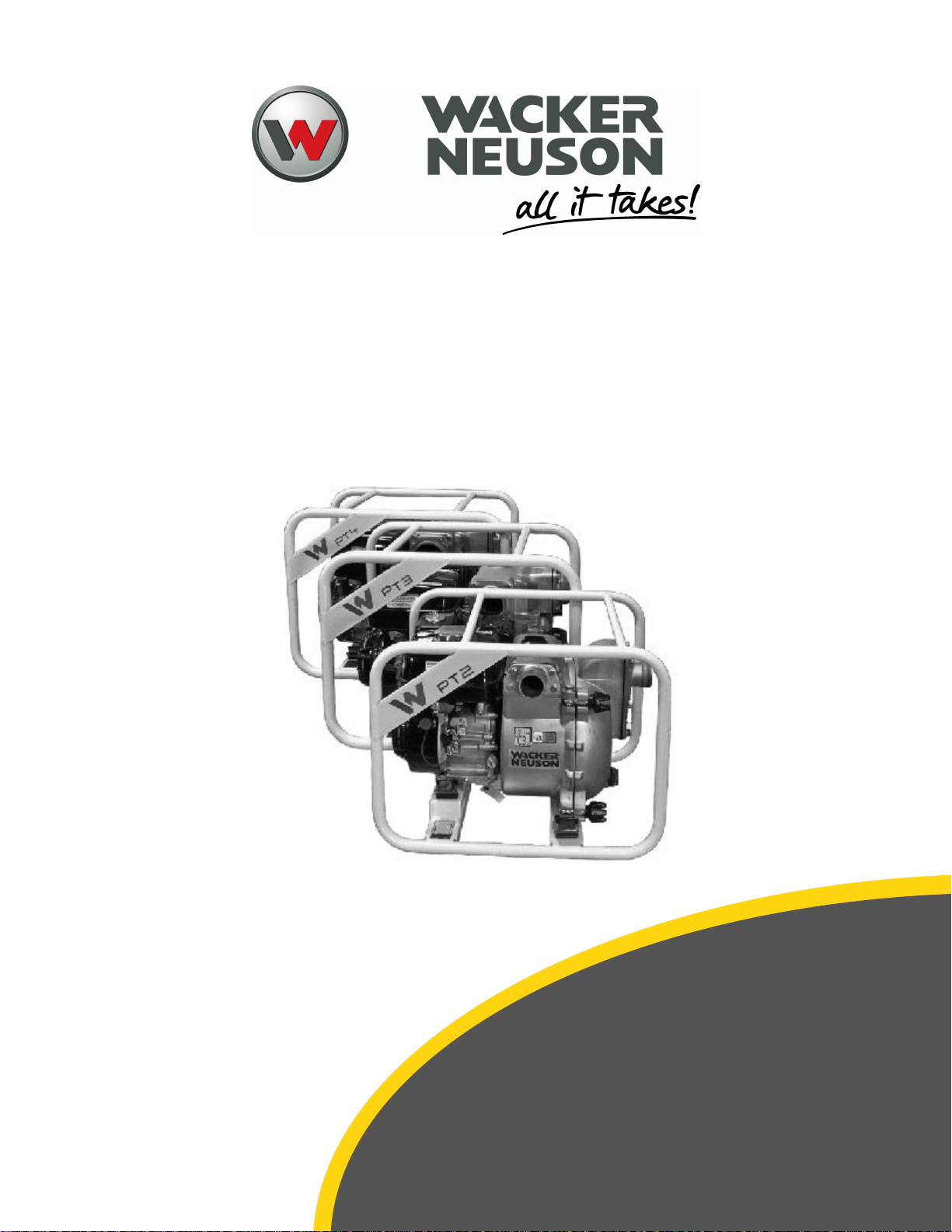
PT Series Trash Pump
Service Manual
Type: PT2, PT3, PT4
Document: 5100048604
Date: 0121
Revision: 0.2 Language:
EN-US
www.wackerneuson.com
Page 2
Copyright notice © Copyright 2021 by Wacker Neuson America Corporation All
rights, including copying and distribution rights, are reserved.
This publication may be photocopied by the original purchaser of the machine. Any
other type of reproduction is prohibited without express written permission from
Wacker Neuson America Corporation.
Any type of reproduction or distribution not authorized by Wacker Neuson America
Corporation represents an infringement of valid copyrights. Violators will be
prosecuted.
Trademarks
Manufacturer
Original instructions
All trademarks referenced in this manual are the property of their respective
owners.
Wacker Neuson America Corporation
N92W15000 Anthony Avenue
Menomonee Falls, WI 53051 U.S.A.
Tel: (262) 255-0500 · Fax: (262) 255-0550 · Tel: (800) 770-0957
www.wackerneuson.com
This Manual presents the original instructions. The original language of this Manual
is American English.
www.wackerneuson.com
Page 3
Foreword
!
Foreword
General
This manual provides detailed information and
procedures to safely repair and maintain the following:
Wacker Neuson PT Series Trash Pump.
This manual is intended to introduce and guide the user
through the latest factory-approved troubleshooting and
repair techniques and practices.
Before you attempt to troubleshoot or make repairs, you
must be familiar with the operation of this machine.
Refer to the operator's manual for specific information on
these topics.
THE INFORMATION CONTAINED IN THIS MANUAL IS
BASED ON MACHINES MANUFACTURED UP TO THE
TIME OF PUBLICATION. WACKER NEUSON
RESERVES THE RIGHT TO CHANGE ANY OF THIS
INFORMATION WITHOUT NOTICE.
California
Proposition 65 Warning
WARNING
Certain vehicle components contain or emit
chemicals known to the State of California to
cause cancer and birth defects or other
reproductive harm.
Trademark Acknowledgment
Wacker Neuson acknowledges the following trademarks
for company names or products mentioned within this
publication:
Lubriplate® is a trademark of Fiske Brothers Refining
Co.
Loctite® and Permatex® are trademarks of Henkel
Corporation.
How to Use This Manual
This manual is designed to provide multiple ways to
locate and access repair information. Read each section
in its entirety before beginning a procedure. Proper
understanding of machine operation and components is
the key to successful diagnostics and repair.
Make use of special information features within this
manual in order to be better prepared to perform repairs.
Always follow manual procedures and safety guidelines.
Never take shortcuts.
Table of Contents
Major machine components or topics of interest are
separated into specific chapters. Each manual lists these
chapters in a main Table of Contents.
Chapter Table of Contents
Each chapter begins with a detailed Table of Contents
related to the specific machine component or system.
Use the Chapter Table of Contents to find specific
component procedural information.
Index
An alphabetical Index is located at the back of the
manual.
Use the Index to find specific components and related
procedures.
Required Tools and Materials
Some procedures will require the use of specific tools
and/or materials. These tools and/or materials will be
listed for reference prior to beginning a procedure.
Specifications
Near the beginning of each chapter is a specifications
list. This listing contains any specifications contained
within the chapter.
Warnings and Cautions
Warning and Caution indicators are located throughout
the manual at specific points of interest. These notices
are given to prevent personal injury, death, and/or
equipment damage. Always heed these notices, and
practice common sense when performing any
maintenance or repair procedure.
Notes
Special notes are given in order to draw attention to
detailed instructions. These notes are intended to give
further important information regarding the machine
and/or a step in a procedure.
5100048604 (12-18) 3
Page 4

FOREWORD
Safety
Introduction
Safety is the most important element of any repair
procedure. Knowledge of the procedure to be performed
and safe work habits are essential to preventing death,
personal injury, or property damage. Use the following
statements as a common-sense guide to proper work
and tool-use habits.
Preparing for the Job
Preparation is essential to complete a procedure in a
safe and efficient manner.
Service Training
• Read and understand the instructions contained in
all manuals delivered with the pump.
•
Familiarize yourself with the location and proper
use of all controls and safety devices.
• Only trained personnel shall troubleshoot or repair
problems occurring with the pump. Contact
Wacker Neuson for additional training if
necessary.
• Visit http://www.wackerneuson.us/en/support-usa/
technical-training.html for more information.
Repair Person Qualifications
Work on the electric system, equipment on the
undercarriage, and the steering and brake systems may
be performed only by skilled individuals who have been
specially trained for such work.
Personal Protective Equipment (PPE)
PPE while servicing or maintaining this pump:
Close-fitting work clothes that do not hinder
•
movement.
• Safety glasses with side shields.
• Hearing protection.
• Safety-toed footwear.
• In addition, before servicing or maintaining the
pump:
• Tie back long hair.
• Remove all jewelry (including rings).
Personal Safety Measures
• Follow the specific safety instructions in this
manual.
Apply special care when working on the fuel
•
system due to increased risk of fire.
• Engine block and muffler system become very hot
during operation and require cool-down time after
pump is shut off. Avoid contact with hot parts.
•
Retainer pins can fly out or splinter when struck
with force. Use a brass hammer or a suitable
material between the hammer and pin.
• To reduce the risk of explosions, do not use
starting fluid (for example, ether), especially in
those cases in which a heater or glow plug (intake
air pre-heating) is used at the same time.
Precautions
• Read and understand the service procedures
before performing any service on the pump.
• Remain aware of the pump’s moving parts. Keep
hands, feet, and loose clothing away from the
pump’s moving parts.
• Reinstall the safety devices and guards after
repair and maintenance procedures are complete.
Cleaning
• Ensure the pump is clean and free of debris such
as leaves, paper, cartons, etc.
• Ensure all labels are legible.
• Do not clean the pump while it is running.
• Never use gasoline or other types of fuels or
flammable solvents to clean the pump. Fumes
from fuels and solvents can become explosive.
Preparing Pump for Maintenance
• Prior to performing assembly work on the pump,
make sure no movable parts will roll away or start
moving.
Position on firm and level ground.
•
• Secure pump against unintentional movement.
• Stop engine unless maintenance or repair is
required with engine running.
• Attach warning tag (Do Not Operate) to pump
unless maintenance or repair is required with
engine running.
• Prior to performing assembly work on the pump,
stabilize the area under repair and use proper
lifting and support devices.
General Maintenance Notes
• Make sure all tools and service center equipment
are capable of performing the tasks prescribed.
Do not use malfunctioning or broken tools. Use
certified measuring devices that are routinely
calibrated for accuracy (for example torque
wrench, pressure gauge, or multimeter).
4 5100048604 (12-18)
Page 5
!
!
!
!
!
FOREWORD
• Recycle scrapped parts and drained fluids
according to environmental and hazardous
material requirements. To avoid fire and health
hazards, dispose of soiled shop towels by
approved methods.
Always retighten any screws, electrical
•
connections, or hose connections that may have
been loosened during maintenance and repair.
• Any safety devices removed for setup,
maintenance, or repair purposes must be refitted
and checked immediately upon completion of the
maintenance and repair work.
Pump Modifications
• Do not defeat safety devices.
• Do not modify the pump without the express
written approval of Wacker Neuson.
• Do not make any modifications, additions, or
conversions to the pump and its superstructures
or the pump's attachments without the approval of
Wacker Neuson. Such modifications may affect
safety and/or pump performance. This also
applies to the installation and adjustment of safety
devices. Use only accessories/attachments that
are approved by Wacker Neuson.
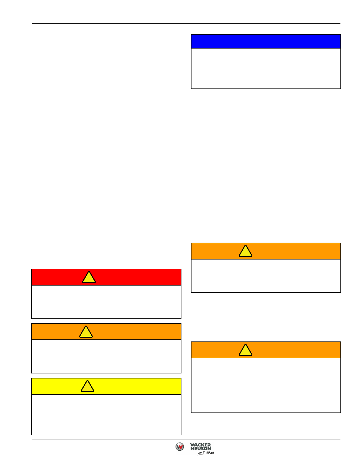
Safety Symbols Found in This Manual
Throughout this manual, the following key safety words
will be used to alert the reader of potential hazards.
Become familiar with these words and their meanings.
Take all precautions to avoid the hazards described.
DANGER
NOTICE
Indicates a potentially hazardous situation
which, if not avoided, MAY result in property
damage. It may also be use to alert against
unsafe practices.
Safety Label Inspection
Safety labels are critical to the safe operation of the
pump. Inspect the pump for any damaged, missing, or
unreadable labels. Replace labels as needed before
placing the pump back in service.
Keep Work Area Clean
A clean, organized, well-lit work area is important to
promote safe working conditions.
•
Keep floor clean of debris and clear of parts and
tools.
• Clean up any spilled fuel, oil, and/or chemicals
immediately.
• Store all air hoses and electrical cords properly
when not in use.
Keep Work Area Well-Ventilated
WARNING
Never operate the engine without proper
ventilation. Exhaust fumes can be fatal if
inhaled.
Indicates an imminently hazardous situation
which, if not avoided, WILL result in death or
serious injury.
WARNING
Indicates a potentially hazardous situation
which, if not avoided, COULD result in death or
serious injury.
CAUTION
Indicates a potentially hazardous situation
which, if not avoided, MAY result in minor or
moderate injury and property damage. It may
also be used to alert against unsafe practices.
5100048604 (12-18) 5
Certain test and adjustment procedures require the
engine to be running. Be sure work area is well
ventilated. Never run the engine in an enclosed area.
Use Proper Eye and Face Protection
WARNING
Always use approved personal protection
equipment. Avoid workplace hazards by
wearing properly maintained, approved eye and
face protection. Failure to use appropriate
protection equipment may result in serious
injury or death.
Always wear eye protection while in a shop environment.
Page 6

FOREWORD
• Safety Glasses: Safety glasses offer a minimum
level of protection from flying debris.
• Face Shields: Face shields are often used along
with safety glasses to offer a higher level of
protection when sparks and flying debris are
present.
• Vented Goggles: Goggles offer side protection not
offered by safety glasses alone.
• Unvented Goggles: Unvented goggles offer
protection from chemical splashes and vapors.
6 5100048604 (12-18)
Page 7
!
!
Support Pump Securely
1. Place the pump on a solid, level surface.
2. Secure the pump against unintentional movement.
3. Stop engine, unless maintenance or repair is
required with engine running.
4. Attach Do Not Operate warning tag to pump.
5. Do not use wood or concrete blocks to support the
pump. Failure to properly support the pump may
result in death or serious injury.
Use Lifting Equipment Safely
WARNING
Always check the lifting capacity and condition
of hoists, slings, cables, or chains before use.
Using underrated or worn lifting components
can result in death or serious injury.
FOREWORD
• Never point air nozzles directly at skin.
• Compressed air is a useful tool when used in a
safe manner.
• Always use eye and ear protection while using
compressed air and air tools.
• When using air tools, do not exceed the air
pressure rating for the tool.
• When using an impact wrench, always use
approved impact sockets. Never use standard
sockets on an impact wrench.
• Disconnect the air supply before changing air tool
attachments.
• Always properly maintain air tools.
• Always use a lifting device with a lifting capacity
greater than the weight of the item being lifted.
• Secure the load to the lifting device using cables,
chains, or slings rated to handle the load being
lifted. Fasteners being used to connect lifting
devices must be strong enough to handle the
load. Be sure the mounting point of load is strong
enough to handle the load.
• When using a lifting device, always connect the
load so it is balanced.
• Always use a lifting device on a hard, level
surface.
• Lower the lifting device to the lowest point before
moving. Move the load slowly.
• Always support the load as soon as possible.
Never leave a load suspended in mid-air.
Use Compressed Air and Air Tools Safely
WARNING
Always wear approved eye and ear protection
while using compressed air. Misuse of
compressed air could result in death or serious
injury.
• When using air nozzles, air pressure should not
exceed 30 psi (206.8 kPa).
• Never direct air nozzles or tools at a person.
5100048604 (12-18) 7
Page 8
!
!
FOREWORD
Handle Fuel Safely
WARNING
• Never remove the fuel cap from the fuel
tank or add fuel when the engine is
running or while the engine is hot.
• Do not smoke when handling fuel. Never
fill or drain the fuel tank indoors.
• Do not spill fuel. Clean spilled fuel
immediately.
• Never handle or store fuel containers
near an open flame or any device that
may create sparks and ignite the fuel or
fuel vapors.
• Be sure to reinstall and tighten fuel cap
securely.
• Use an approved container; the spout
must fit inside the fuel filler neck. Avoid
using cans and funnels to transfer fuel.
Routine service often requires the use of various
chemical products, including lubricants and cleaning
solutions. Many of these chemicals are flammable and
can pose health risks if not handled properly.
• Never mix chemicals. Mixing chemicals can
produce toxic or explosive results.
• Follow the manufacturer’s recommendations for
safe usage and handling of the product.
• Various materials may pose a health hazard if
used incorrectly. An MSDS contains important
information regarding proper handling and health
hazards, as well as emergency response
procedures. Contact the chemical manufacturer to
obtain an MSDS for the chemical product.
• Store fuel according to local, state, or federal
ordinances and recommendations from your fuel
supplier.
• Never overfill or allow the tank to become empty.
• Use clean, fresh fuel.
• Do not fill above the fuel filler neck.
Store Volatile and Hazardous Materials Safely
Store volatile materials (for example, gasoline, diesel
fuel, oil, etc.) in approved containers that are clearly
marked. Containers should be stored in an approved
safety cabinet away from possible sources of ignition.
Storage areas and cabinets should be well-ventilated to
prevent the possible build-up of fumes.
Handle Chemical Products Safely
WARNING
Exposure to chemical products could result in
serious injury. Handle chemical products with
care.
Refer to the chemical manufacturer’s Material
Safety Data Sheet (MSDS) for information
regarding health hazards, safe handling, and
emergency response procedures.
8 5100048604 (12-18)
Page 9

!
Service Electrical Components Safely
WARNING
FOREWORD
environment. Collect fluids in well-marked, approved
storage containers. Some waste fluids can react with
certain types of plastics. Make sure the fluid to be stored
is compatible with the storage container. Never use food
or beverage containers to store waste fluids.
Always disconnect the negative terminal first
and positive terminal last. Connect positive
terminal first and negative terminal last. Use
care when testing live circuits to prevent
arcing. Arcing could result in death or serious
injury.
• Make sure circuit breakers are open (off).
• Disconnect the battery negative (–) cable before
removing or installing electrical components.
Always connect the battery negative (–) cable last.
• Certain test and adjustment procedures must be
performed with the battery connected. Use care to
prevent arcing when working on live circuits or
components. Arcing can cause component
damage and could ignite flammable materials.
Dispose of Waste Materials Safely
Routine service can produce waste products such as
used oil, coolant, grease, and batteries. If not handled
properly, these materials can pose a threat to the
NOTICE
• Dispose of waste fluids properly at
approved local recycling centers. If
recycling facilities are not available,
contact your local community for the
correct disposal procedure for waste
fluids.
• Dispose of old batteries properly. Battery
electrolyte contains sulfuric acid and
other hazardous materials. Never place
an old battery in the trash. Batteries must
be disposed of in a manner consistent
with EPA and/or local regulations.
5100048604 (12-18) 9
Page 10

Page 11

Table of Contents
Specification and General
Information
1
Maintenance
Troubleshooting
2
3
5100048604 (12-18) 11
Page 12

Page 13

Chapter 1
Specification and General Information
Standard Torque Values ................................................................. 1-2
Torque Values ....................................................................1-2
General Specifications ...................................................................1-6
General Specifications ..............................................................1-6
1
5100048604 (12-18) 1-1
Page 14
62363
1
2
3
4
5
6
7
8
9
10
11
12
62365
1
2
3
4
5
6
!
SPECIFICATION AND GENERAL INFORMATION
1
Standard Torque Values
Torque Values
1. Always use torque values listed in Table 1-1,
Torque Limits - SAE Standard Fasteners and Table
1-2, Torque Values for Lubricated or Plated Metric
Thread Fasteners when a maintenance procedure
does not provide a specific torque value.
2. Unless otherwise indicated, standard torque
tolerance shall be ±10 percent.
3. Torque values listed are based on clean, dry
threads.
a. Reduce torque by 25 percent when engine oil is
used as a lubricant.
b. Reduce torque by 25 percent if new plated cap
screws are used.
4. If the maintenance procedures do not specify a
tightening order, use the following guidelines:
a. Lubricate threads of fasteners as specified in work
procedure or Table 2.
b. Tighten fasteners above 30 lb-ft (41 N•m) using
torque pattern and tighten to 70 percent of final
value.
c. Multiply final value by 0.7 and torque to
specifications.
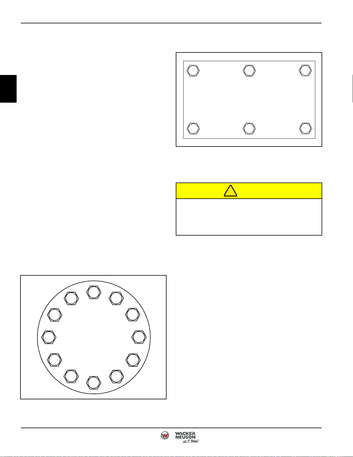
f. Tighten straight patterns using Figure 1-2, Straight
Torque Pattern.
Figure 1-2: Straight Torque Pattern
SAE Standard Fasteners Torque Limits
CAUTION
If replacement cap screws are of a higher grade
than originally supplied, use torque
specifications for original cap screw. Failure to
comply may result in damage to equipment.
d. Use torque pattern to torque to final value.
e. Tighten circular patterns using Figure 1-1, Circular
Torque Pattern.
Figure 1-1: Circular Torque Pattern
1-2 5100048604 (12-18)
Page 15

Table 1-1. Torque Limits - SAE Standard Fasteners
SPECIFICATION AND GENERAL INFORMATION
Cap Screw Head Markings
(Manufacturer’s Marks May Vary)
SIZE
DIA. INCHES
1/4
1/4
5/16
5/16
3/8
3/8
7/16
7/16
1/2
1/2
9/16
9/16
5/8
5/8
3/4
3/4
7/8
7/8
1
1
1-1/8
1-1/8
1-1/4
1-1/4
1-3/8
1-3/8
1-1/2
1-1/2
THREADS PER
INCH
20
28
18
24
16
24
14
20
13
20
12
18
11
18
10
16
9
14
8
12
7
12
7
12
6
12
6
12
TORQUE
SAE GRADE
NO. 1 or 2 and
General Hardware
lb-ft (N•m) lb-ft (N•m) lb-ft (N•m) lb-ft (N•m)
5 (7)
6 (8)
11 (15)
12 (16)
20 (27)
23 (31)
30 (41)
35 (47)
50 (68)
55 (75)
65 (88)
75 (102)
90 (122)
100 (136)
160 (217)
180 (244)
140 (190)
155 (210)
220 (298)
240 (325)
300 (407)
340 (461)
420 (569)
460 (624)
560 (759)
640 (868)
740 (1003)
840 (1139)
SAE GRADE NO.5SAE GRADE NO.
6 or 7
8 (11)
10 (14)
17 (23)
19 (26)
30 (41)
35 (47)
50 (68)
55 (75)
75 (102)
90 (122)
110 (149)
120 (163)
150 (203)
180 (244)
260 (353)
300 (407)
400 (542)
440 (597)
580 (786)
640 (868)
800 (1085)
880 (1193)
1120 (1519)
1240 (1681)
1460 (1980)
1680 (2278)
1940 (2630)
2200 (2983)
10 (14)
12 (16)
21 (28)
24 (33)
40 (54)
45 (61)
60 (81)
70 (95)
95 (129)
100 (136)
135 (183)
150 (203)
190 (258)
210 (285)
320 (434)
360 (488)
520 (705)
580 (786)
800 (1085)
860 (1166)
1120 (1519)
1260 (1708)
1580 (2142)
1760 (2386)
2080 (2820)
2380 (3227)
2780 (3769)
3100 (4203)
SAE GRADE NO.
900 (1220)
1000 (1356)
1280 (1735)
1440 (1952)
1820 (2468)
2000 (2712)
2380 (3227)
2720 (3688)
3160 (4285)
3560 (4827)
8
1
12 (16)
14 (19)
25 (34)
45 (61)
50 (68)
70 (95)
80 (108)
110 (149)
120 (163)
150 (203)
170 (230)
220 (298)
240 (325)
380 (515)
420 (569)
600 (813)
660 (895)
5100048604 (12-18) 1-3
Page 16
1
SPECIFICATION AND GENERAL INFORMATION
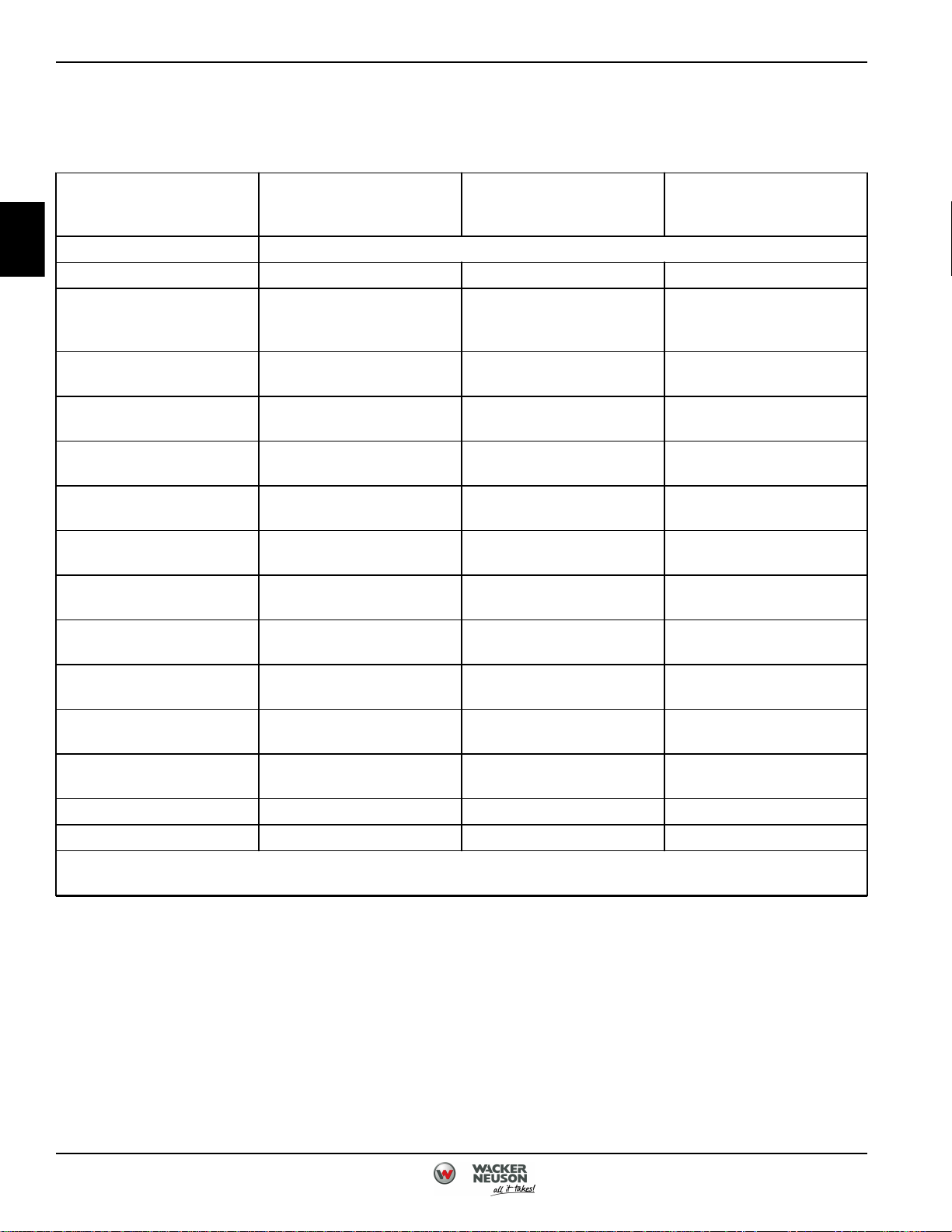
Metric Fasteners Torque Limits
Table 1-2. Torque Limits - Torque Values for Lubricated or Plated Metric Thread Fasteners
Cap Screw Head Markings
(Manufacturer’s Marks
May Vary)
Thread Diameter-Pitch Torque: lb-ft (N•m)
DIA. INCHES lb-ft (N•m) lb-ft (N•m) lb-ft (N•m)
M6M8
M8 X 1.25
M10
M10 X 1.25
M12
M12 X 1.5
M14
M14 X 1.5
M16
M16 X 1.5
M18
M18 X 1.5
M20
M20 X 1.5
M22
M22 X 1.5
M24
M24 X 2
M27
M27 X 2
M30
M30 X 2
M33 1300 (1763) 1850 (2508) 2150 (2915)
M36 2100 (2847) 3000 (4067) 3500 (4745)
*Coat plated and unplated fasteners with oil before installation.
+Use if bolt or nut is lubricated or plated (zinc-phosphate conversion-coated, cadmium-plated, or waxed).
Class 8.8* or 9.8+ Class 10.9* Class 12.9
5 (7)
12 (16)
13 (18)
24 (33)
27 (37)
42 (57)
43 (58)
66 (89)
72 (98)
103 (140)
110 (149)
147 (199)
165 (224)
208 (282)
213 (289)
283 (384)
315 (427)
360 (488)
392 (531)
527 (715)
569 (771)
715 (969)
792 (1074)
7 (9)
17 (23)
18 (24)
34 (46)
38 (52)
60 (81)
62 (84)
95 (129)
103 (140)
148 (201)
157 (213)
203 (275)
320 (434)
288 (390)
320 (434)
392 (531)
431 (584)
498 (675)
542 (735)
729 (988)
788 (1068)
990 (1342)
1096 (1486)
12 (16)
30 (41)
29 (39)
70 (95)
60 (81)
120 (163)
190 (258)
300 (407)
410 (556)
580 (786)
800 (1085)
1000 (1356)
1475 (2000)
2000 (2712)
1-4 5100048604 (12-18)
Page 17
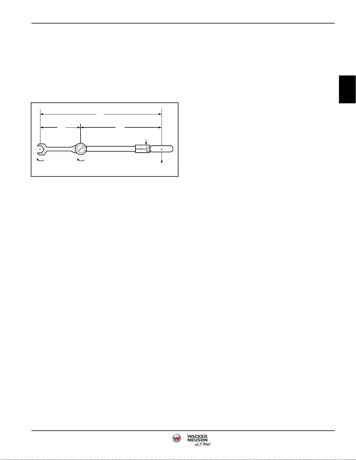
62364
L
F
T
W
T
S
T
E
L
E
L
W
Using a Torque Wrench Extension
Occasionally an extension, crowfoot, or other adapter is
necessary to use with a torque wrench to torque a bolt or
line fitting. Adding adapters or extensions will alter the
torque on the fastener from what the torque wrench
reads. Use the following formula to calculate the correct
torque wrench setting to achieve a specific torque value.
Figure 1-3: Torque Wrench and Extension
SPECIFICATION AND GENERAL INFORMATION
1
F - Force applied by technician
L - Total length through which force is applied to fastener
TW - Torque applied at end of torque wrench
TS = TE (LW / (LW + LE))
TS - Torque wrench setting
TE - Torque specified at fastener
LW - Length of torque wrench
LE - Length of extension
Example: A component requires a specified torque value
of 65 lb-ft and a 6 inch extension is required to reach it.
What should the torque wrench setting (TS) be to
compensate for the extension?
Torque specified at fastener (TE) = 65 lb-ft
Length of torque wrench (LW) = 12 in.
Length of extension (LE) = 6 in.
TS = TE (LW / (LW + LE))
TS = 65 lb-ft (12 in. / (12 in. + 6 in.)
TS = 65 lb-ft (12 in. / (18 in.)
TS = 65 lb-ft (0.666)
TS = 43.33 lb-ft
5100048604 (12-18) 1-5
Page 18
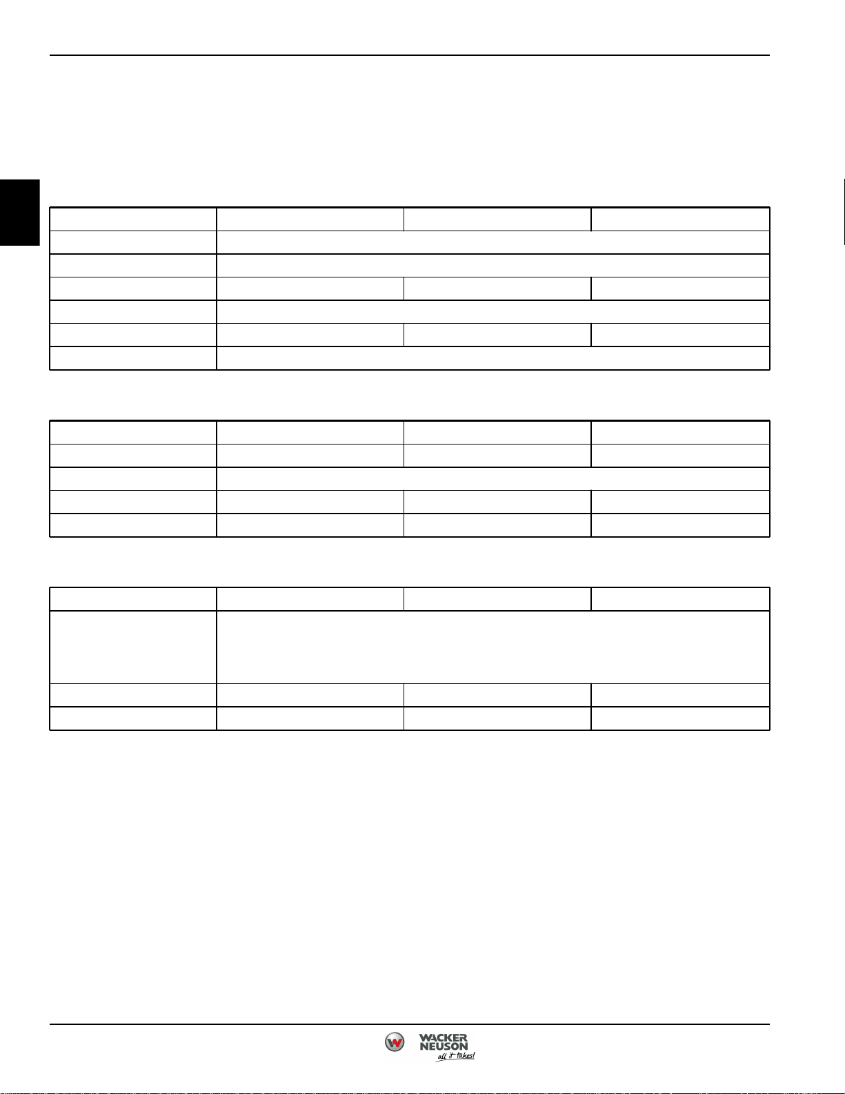
SPECIFICATION AND GENERAL INFORMATION
General Specifications
General Specifications
Engine
1
Engine Model GX 160 GX 270 GX 390
Engine Make Honda
Engine Type 4-stroke, 2-cylinder, air-cooled
Displacement 9.95 in³ (163 cm³) 16.48 in³ (270 cm³) 23.74 in³ (389 cm³)
Fuel Type Regular unleaded gasoline
Fuel Tank Capacity 0.8 gal (3.1 L) 1.4 gal (5.3 L) 1.6 gal (6.1 L)
Starting System Recoil Starter
Pump
Model PT2 PT3 PT4
Connection Diameter 2 in. (50 mm) 3 in. (80 mm) 4 in. (100 mm)
Connection Thread Parallel Pipe Thread or NPT
Total Head 98 ft (30 m) 89 ft (27 m) 98 ft (30 m)
Discharge Volume 185 gal/min (700 L/min) 383 gal/min (1450 L/min) 542 gal/min (2050 L/min)
Complete Pump Assembly
Model PT2 PT3 PT4
(1) strainer
Standard Accessory
(1) multi-tool for pump cover and plugs
Net Weight 104 lb (47 kg) 146 lb (66 kg) 181 lb (82 kg)
Guaranteed Sound Power LWA 105 dB LWA 105 dB LWA 106 dB
(1) barbed fitting
(2) wire hose clamps
1-6 5100048604 (12-18)
Page 19

SPECIFICATION AND GENERAL INFORMATION
1
5100048604 (12-18) 1-7
Page 20

1
SPECIFICATION AND GENERAL INFORMATION
Page Intentionally Blank
1-8 5100048604 (12-18)
Page 21

Chapter 2
Maintenance
Maintinance and Testing .................................................................2-2
Engine Oil Drain/Fill Procedure .......................................................2-2
Pump Priming and Operation ........................................................2-3
After Use ........................................................................ 2-4
Front Cover ......................................................................2-5
Suction Test ......................................................................2-6
Suction and Discharge Flange .......................................................2-7
Spark Plug Inspection ..............................................................2-7
Mechanical Seal ...................................................................2-8
2
5100048604 (12-18) 2-1
Page 22
!
!
!
MAINTENANCE
2
Maintinance and Testing
Engine Oil Drain/Fill Procedure
Drain/Fill
NOTE
The oil drain/fill procedure is the same on all pumps.
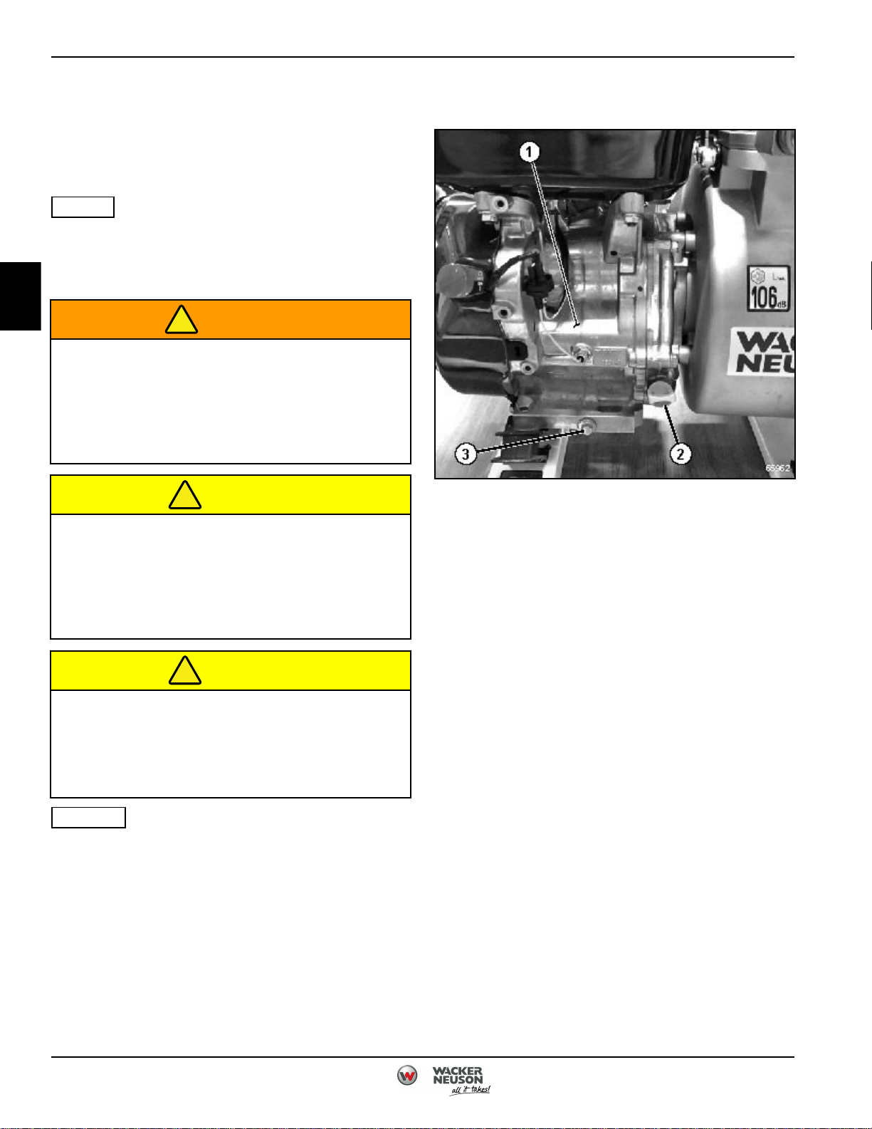
PT4 is shown.
See Figure 2-1.
WARNING
Prolonged contact with lubricating oil may
cause skin rash. Remove saturated clothing
immediately and thoroughly wash skin that
comes in contact with lubricating oil. Failure to
comply may result in injury or death to
personnel.
CAUTION
1. Support pump securely. (See
"Support Pump Securely" on page 7.)
Figure 2-1: Engine Oil Tank Drain/Fill Procedure
Wipe clean area around all fluid connections
prior to removal. Cap and plug all hoses, lines,
fittings, and ports during removal to prevent
contamination of system components. System
must be kept clean from contaminants. Failure
to comply may result in damage to equipment.
CAUTION
Ensure oil proper engine oil level prior to each
startup. The engine manufacturer will not
warranty damages caused due to low oil
situations. Failure to comply may result in
damage to equipment.
NOTES
• Oil should be changed every 8 hours of use for
the first 20 hours of operation.
• Oil should be changed every 50 hours after the
first 20 hours of operation.
• SAE#30 should be used during spring and
summer months.
• SAE#20 should be used in during autumn and
winter months.
• SAE10W-30 should be used in any conditions
50° F (10° C) and below.
2. Position suitable drain pan under the engine (1).
3. Remove the filler cap (2) from engine (1)
4. Remove drain plug (3) and sealing washer from
engine (1). Allow engine oil to completely drain into
drain pan.
Installation Notes
• Install drain plug and sealing washer.
• Ensure pump is on a level surface.
• Fill engine oil to the upper fill limit.
• Install filler cap.
• Start engine. Check for leaks. Repair as
necessary.
• Check engine oil and add if necessary.
2-2 5100048604 (12-18)
Page 23
!
!
!
!
!
!
!
MAINTENANCE
Pump Priming and Operation
Priming Pump
NOTE
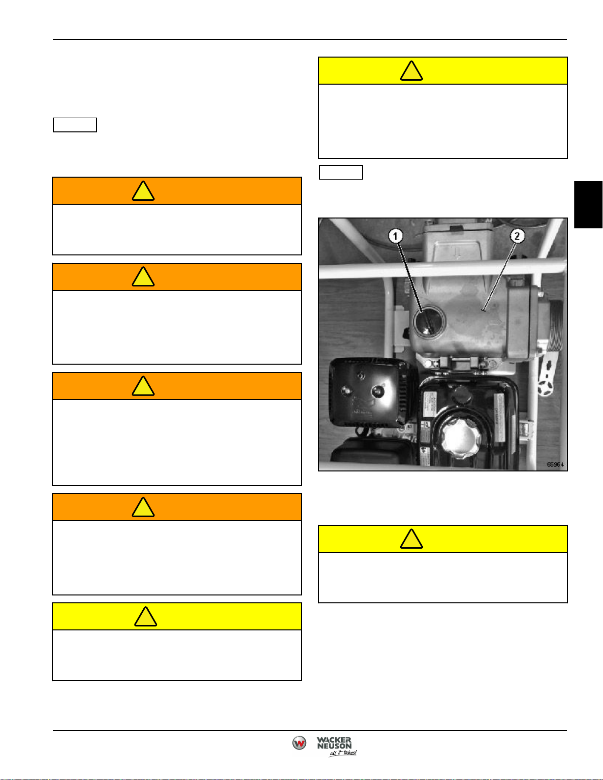
All pumps are primed in a similar fashion. PT4 is shown.
See Figure 2-2.
WARNING
When priming the pump, only use water.
Failure to comply may result in injury or death
to personnel.
WARNING
Do not prime pump for more than 5 minutes. If
pump priming is taking longer than 5 minutes,
turn off engine and allow pump to cool. Failure
to comply may result in injury or death to
personnel.
CAUTION
inspect hoses to ensure they are the correct
diameter and free of damage. If the hose
diameter is to small or the hose is damaged, it
will cause the pump to cavitate. Failure to
comply may result in damage to equipment.
NOTE
To avoid air leaks and slow priming, ensure the suction
hose is connected properly.
2
WARNING
High temperatures and/or pressures may be
caused during priming or operation. If high
temperatures and/or pressure conditions exist,
do not open any plugs or hoses. Failure to
comply may result in injury or death to
personnel.
WARNING
Ensure discharge hose is secure before
operating the pump. A loose discharge hose
may cause the hose to slip or become
detached. Failure to comply may result in injury
or death to personnel.
CAUTION
Inspect pump and associated accessories
before each use. Failure to comply may result
in damage to equipment.
Figure 2-2: Pump Priming
1. Install suction hose on pump (2).
CAUTION
Do not run pump before filling with water.
Failure to comply may result in damage to
equipment.
2. Remove fill cap (1) from pump (2).
3. Completely fill pump (2) with water.
4. Install fill cap (1) on pump (2).
5100048604 (12-18) 2-3
Page 24
!
!
!
!
!
!
!
!
MAINTENANCE
2
Pump Operation
WARNING
High temperatures and/or pressures may be
caused during priming or operation. If high
temperatures and/or pressure conditions exist,
do not open any plugs or hoses. Failure to
comply may result in injury or death to
personnel.
WARNING
Ensure discharge hose is secure before
operating the pump. A loose discharge hose
may cause the hose to slip or become
detached. Failure to comply may result in injury
or death to personnel.
CAUTION
inspect pump and associated accessories
before each use. Failure to comply may result
in damage to equipment.
WARNING
Do not dead head or restrict water flow either at
suction or discharge side of the pump. This will
cause high air pressure and/or high
temperature conditions. Failure to comply may
result in injury or death to personnel.
4. Ensure discharge and suction hoses are free of any
kinks, blockages, or obstructions.
CAUTION
Do not allow any vehicle to run over the
delivery hose or close the delivery valve
abruptly. This may cause waterhammering.
Failure to comply may result in damage to
equipment.
5. Start pump.
After Use
Draining Pump
CAUTION
Inspect hoses to ensure they are the correct
diameter and free of damage. If the hose
diameter is too small or the hose is damaged, it
will cause the pump to cavitate. Failure to
comply may result in damage to equipment.
1. Install suction hose on pump.
CAUTION
Do not operate pump before filling with water.
Failure to comply may result in damage to
equipment.
2. Prime pump. (See "Priming Pump" on page 2-3.)
3. Submerge strainer at the end of the suction hose in
water. Ensure the strainer is suspended above any
dirt or debris that may be at the bottom of the water
being pumped.
NOTE
All pumps are drained in a similar fashion. PT4 is shown.
See Figure 2-3.
CAUTION
Ensure all water is drained from pump after
use. Water left in pump may freeze and expand,
damaging components. Failure to comply may
result in damage to equipment.
1. Support pump securely. (See
"Support Pump Securely" on page 7.)
2-4 5100048604 (12-18)
Page 25
!
See Figure 2-4.
MAINTENANCE
WARNING
High temperatures and/or pressures may be
caused during priming or operation. If high
temperatures and/or pressure conditions exist,
do not open any plugs or hoses. Failure to
comply may result in injury or death to
personnel.
1. Support pump securely. (See
"Support Pump Securely" on page 7.)
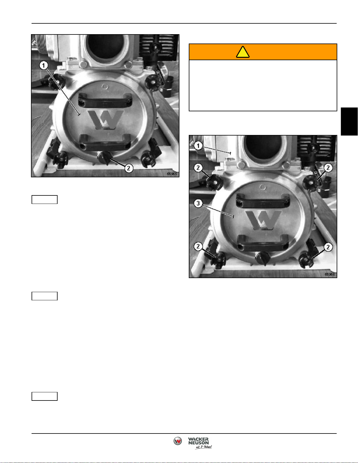
Figure 2-3: Draining Pump
2
NOTE
The number of drain plugs and drain plug locations vary
depending on model.
2. Remove the water drain plug(s) (2) from bottom of
pump (1), allowing water to drain.
3. Tilt pump (1) so remaining water and sediment will
drain from pump (1). Ensure all sediment is drained.
4. Tilt pump (1) so remaining water and sediment will
drain from suction and discharge ports. Ensure all
sediment is drained.
NOTE
If the pump is used to transfer muddy water, sand and
dirt will accumulate in the pump casing. This will make it
difficult to remove the front cover.
5. If pump was used to transfer muddy water, remove
front cover and clean the inside of pump prior to
storage. (See
"Removal and Installation" on page 2-5.)
Front Cover
Removal and Installation
NOTE
Figure 2-4: Front Cover Removal and Installation
2. Loosen knobs (2) securing front cover (3) to pump
(1) using tool supplied with pump.
3. Pull front cover (3) away from pump (1) evenly,
ensuring O-ring is does not become damaged.
4. Remove front cover (3) from pump (1).
Installation Notes
• Install front cover by reversing the order of
removal.
• Ensure front cover seal is undamaged prior to
installation.
• Tighten front cover fasteners evenly.
All front covers are removed the same way. PT4 is
shown.
5100048604 (12-18) 2-5
Page 26
2
MAINTENANCE
Suction Test
NOTE
The suction test is perfomed the same way on all
pumps. PT4 is shown.
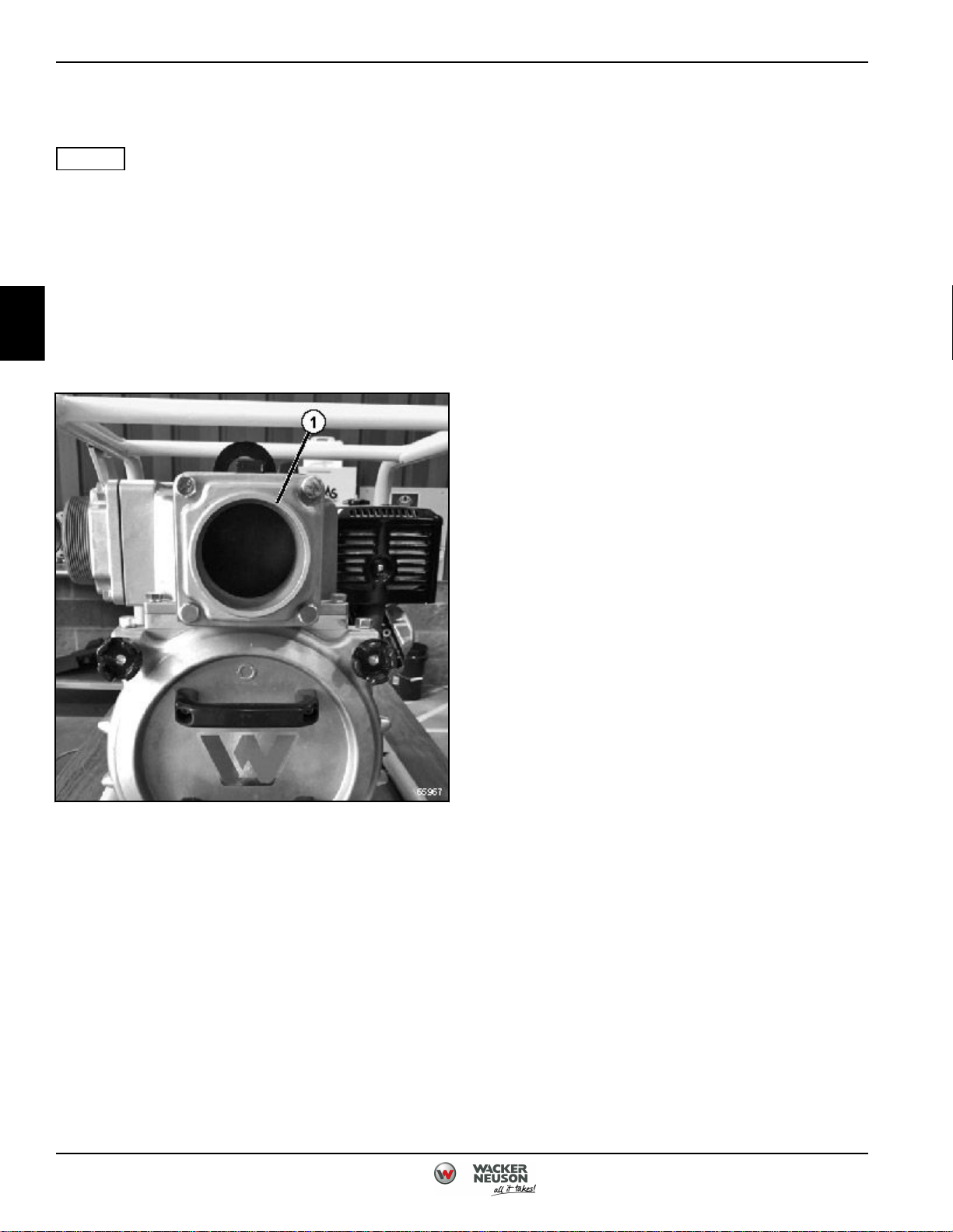
See Figure 2-5.
1. Support pump securely. (See
"Support Pump Securely" on page 7.)
2. Remove suction hose.
3. Prime pump. (See "Inspection" on page 2-7.)
4. Start engine.
7. Inspect suction hose for holes, crushing, or any
other damage.
Is suction hose free of holes, crushing, or
damage?
YES Proceed to Step 8.
NO Hose is damaged. Replace suction hose.
8. Remove front cover. (See
" Front Cover" on page 2-5.)
9. Inspect the impeller for debris or blockage.
Is the impeller free of any blockage or debris?
YES Proceed to Step 10.
NO Impeller is blocked. Remove any
blockage or debris.
10. Inspect impeller for damage.
Is the impeller free of any damage?
YES Pump suction is good. Inspect hoses and
strainer for damage or clogging.
Figure 2-5: Suction Port
5. Place palm of hand over the suction port (1) for 30
seconds.
Is suction present?
YES Pump suction is good. Inspect hoses and
strainer for damage or clogging
NO Impeller is damaged. Replace impeller.
NO Proceed to Step 6.
6. Inspect the suction hose for packing.
Is the packing present and undamaged?
YES Proceed to Step 7.
NO Missing or damaged packing. Replace
packing.
2-6 5100048604 (12-18)
Page 27
!
!
MAINTENANCE
Suction and Discharge Flange
Removal and Installation
NOTE
All suction and discharge flanges are removed the same
way. PT4 is shown.
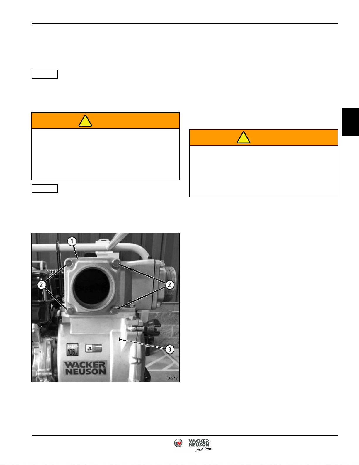
See Figure 2-6.
WARNING
High temperatures and/or pressures may be
caused during priming or operation. If high
temperatures and/or pressure conditions exist,
do not open any plugs or hoses. Failure to
comply may result in injury or death to
personnel.
NOTE
Both discharge and suction flanges are removed the
same way. The discharge flange is shown.
1. Support pump securely. (See
"Support Pump Securely" on page 7.)
Installation Notes
• Install discharge flange by reversing the order of
removal.
• Ensure discharge flange seal is undamaged prior
to installation.
• Torque discharge flange mounting screws to 7.4
lb-ft (10 N•m).
Spark Plug Inspection
Inspection
2
WARNING
Prolonged contact with lubricating oil may
cause skin rash. Remove saturated clothing
immediately and thoroughly wash skin that
comes in contact with lubricating oil. Failure to
comply may result in injury or death to
personnel.
1. Support pump securely. (See
"Support Pump Securely" on page 7.)
2. Remove spark plug.
3. Using a clean cloth, remove any fuel and dirt from
spark plug.
Figure 2-6: Discharge Flange Removal and
Installation
2. Remove screws (2) securing discharge flange (1) to
pump (3). Remove discharge flange (1) from pump
(3).
4. Using apropriate tool, adjust spark plug gap to
0.024 - 0.028 in. (0.6 - 0.7 mm) gap.
5. Install spark plug.
6. Attempt to start pump.
7. If pump does not start, replace spark plug.
5100048604 (12-18) 2-7
Page 28
!
2
MAINTENANCE
Mechanical Seal
Inspection
NOTE
All mechanical seals are inspected the same way. PT4 is
shown.
See Figure 2-7.
See Figures 2-8 through 2-11.
WARNING
High temperatures and/or pressures may be
caused during priming or operation. If high
temperatures and/or pressure conditions exist,
do not open any plugs or hoses. Failure to
comply may result in injury or death to
personnel.
1. Support pump securely. (See
"Support Pump Securely" on page 7.)
2. Remove front cover. (See
" Front Cover" on page 2-5.)
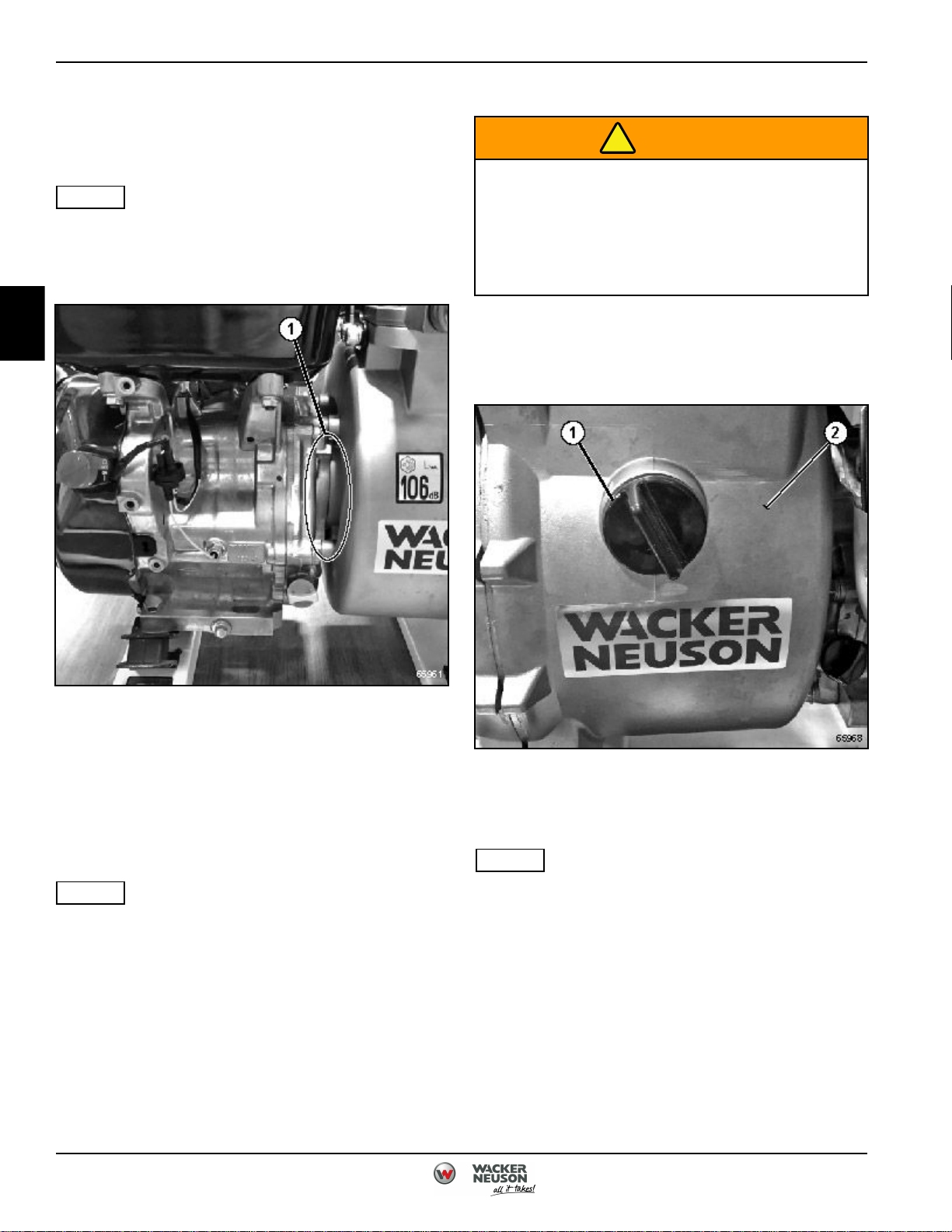
Figure 2-7: Mechanical Seal Inspection
1. Inspect area between pump casing and engine (1)
for water leaks.
2. If water is leaking between pump casing and
engine, replace the mechanical seal. (See
"Removal and Installation" on page 2-8.)
Removal and Installation
NOTE
All mechanical seals are removed in a similar fashion.
PT4 is shown.
Figure 2-8: Impeller Plug
3. Remove impeller plug (1) from pump (2).
NOTE
If available, an impact wrench can be used to loosen the
impeller on PT3 and PT4 models.
2-8 5100048604 (12-18)
Page 29
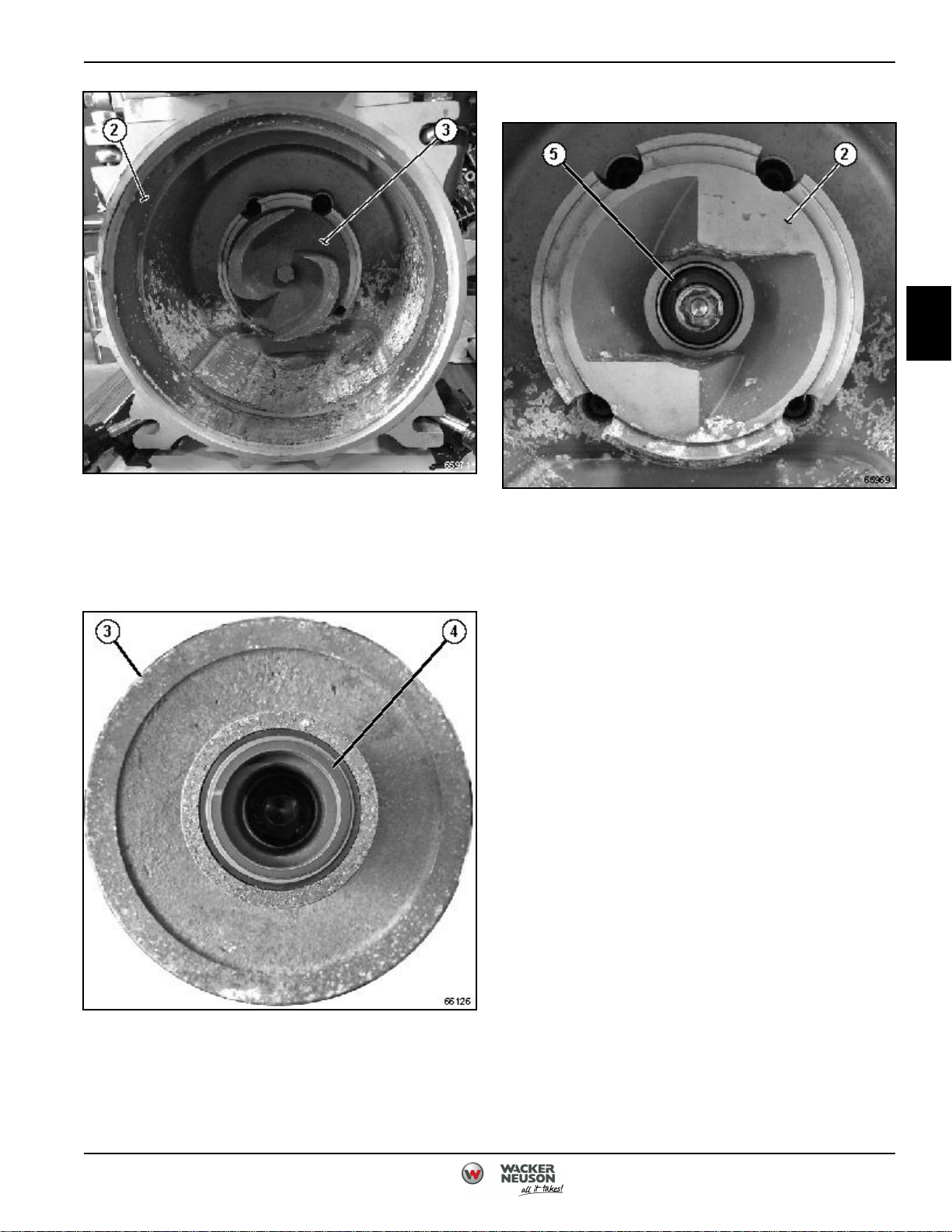
6. Remove the mechanical seal (4) from impeller (3).
MAINTENANCE
2
Figure 2-9: Impeller Removal and Installation
4. Using appropriate punch or drift and hammer,
loosen the impeller (3) by hammering impeller
counterclockwise.
5. Remove the impeller (3) from pump (2).
Figure 2-11: Pump Mechanical Seal Removal and
Installation
7. Use two suitable tools to evenly pry the machine
seal (5) away from the pump (2).
Installation Notes
• Install mechanical seal by reversing the order of
removal.
• Ensure all sealing surfaces are clean prior to
installation.
• Ensure seals are fully set.
• Replace impeller adjusting washer.
• Use a mallet or soft hammer to tighten the
impeller.
Figure 2-10: Impeller Mechanical Seal Removal and
Installation
5100048604 (12-18) 2-9
Page 30

2
MAINTENANCE
Page Intentionally Blank
2-10 5100048604 (12-18)
Page 31

Chapter 3
Troubleshooting
Troubleshooting ........................................................................3-2
Starting Engine ................................................................... 3-2
Pump Functions ...................................................................3-3
Oil Leak .........................................................................3-4
3
5100048604 (12-18) 3-1
Page 32
3
TROUBLESHOOTING
Troubleshooting
Starting Engine
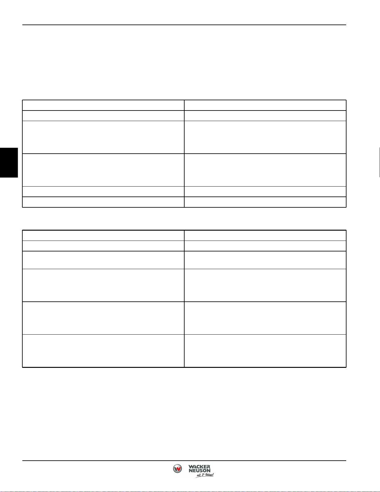
Symptom: Can Not Pull or Hard to Pull Recoil Starter.
Probable Cause Remedy
Old Fuel Replace fuel.
A separate engine manual, prepared by the engine
Rusted Internal Engine Components
Engine Failure
Blockage at Impeller Inlet Clean Impeller. (See " Front Cover" on page 2-5.)
Debris Jamming Impeller Clean Impeller. (See " Front Cover" on page 2-5.)
manufacturer, is supplied with this machine. Refer to the
engine manufacturer’s manual for all engine-related
service.
A separate engine manual, prepared by the engine
manufacturer, is supplied with this machine. Refer to the
engine manufacturer’s manual for all engine-related
service.
Symptom: Engine Does Not Start.
Probable Cause Remedy
Old Fuel Replace fuel.
Faulty or Wet Spark Plug
Engine Oil Level is Too High or Too Low
Dirty or Plugged Air Cleaner
Engine Failure
Replace or clean spark plug as needed. (See
" Spark Plug Inspection" on page 2-7.)
Adjust engine oil level as needed. (A separate engine
manual, prepared by the engine manufacturer, is supplied
with this machine. Refer to the engine manufacturer’s
manual for all engine-related service.)
Replace or clean air cleaner as needed. (A separate
engine manual, prepared by the engine manufacturer, is
supplied with this machine. Refer to the engine
manufacturer’s manual for all engine-related service.)
A separate engine manual, prepared by the engine
manufacturer, is supplied with this machine. Refer to the
engine manufacturer’s manual for all engine-related
service.
3-2 5100048604 (12-18)
Page 33
TROUBLESHOOTING
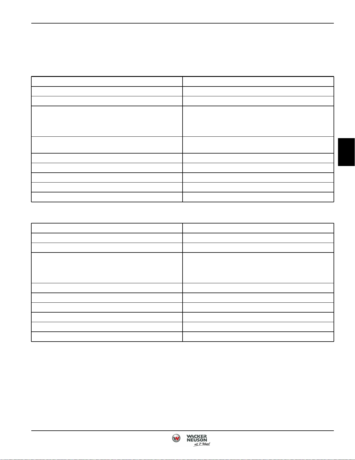
Pump Functions
Symptom: Pump Has Low Delivery Volume.
Probable Cause Remedy
Air Leak at Suction Hose Repair or replace suction hose as needed.
Water Leaking at Delivery Hose Repair or replace delivery hose as needed.
A separate engine manual, prepared by the engine
Engine Failure
Pump Placement Too High
Suction Hose Too Long Replace or shorten suction hose as needed.
Suction Hose Diameter Too Small Replace suction hose.
Blockage at Impeller Inlet Clean impeller. (See " Front Cover" on page 2-5.)
Debris Jamming Impeller Clean impeller. (See " Front Cover" on page 2-5. )
Broken or Damaged Impeller Replace impeller. (See "Mechanical Seal" on page 2-8. )
manufacturer, is supplied with this machine. Refer to the
engine manufacturer’s manual for all engine-related
service.
Move pump lower, so that it is closer to the fluid being
pumped.
3
Symptom: Pump Does Not Prime.
Probable Cause Remedy
Air Leak At Suction Hose Repair or replace suction hose as needed.
Insufficient Water Inside Pump Fill pump with water. (See "Inspection" on page 2-7.)
A separate engine manual, prepared by the engine
Engine Failure
Pump Placement Too High Lower pump closer to the fluid being pumped.
Suction Hose Too Long Replace or shorten suction hose as needed.
Suction Hose Diameter Too Small Replace suction hose.
Blockage at Impeller Inlet Clean impeller. (See " Front Cover" on page 2-5.)
Debris Jamming Impeller Clean impeller. (See " Front Cover" on page 2-5.)
Broken or Damaged Impeller Replace impeller. (See "Mechanical Seal" on page 2-8.)
manufacturer, is supplied with this machine. Refer to the
engine manufacturer’s manual for all engine-related
service.
5100048604 (12-18) 3-3
Page 34
3
TROUBLESHOOTING
Oil Leak
Symptom: Oil Leaks From Muffler or Air Cleaner.
Probable Cause Remedy
Clean or replace the following:
• air cleaner
• carburetor
• muffler
Engine Has Been Tipped Over
• spark plug
(A separate engine manual, prepared by the engine
manufacturer, is supplied with this machine. Refer to the
engine manufacturer’s manual for all engine-related
service.)
3-4 5100048604 (12-18)
Page 35
INDEX
INDEX
Numerics
After Use
Draining Pump .................................. 2-4
Engine Oil Drain/Fill Procedure
Drain/Fill ........................................ 2-2
Front Cover
Removal and Installation ........................ 2-5
Pump Priming and Operation
Priming Pump ................................... 2-3
Pump Operation ................................ 2-4
Spark Plug Inspection
Inspection ....................................... 2-7
Suction and Discharge Flange
Removal and Installation ........................ 2-7
F
Foreward ............................................ 3
G
Starting Engine
Symptom: Can Not Pull or Hard to Pull Recoil
Starter. ...................................... 3-2
Symptom: Engine Does Not Start. .............. 3-2
Suction Test ....................................... 2-6
T
Torque Values
Metric Fasteners Torque Limits ................. 1-4
SAE Standard Fasteners Torque Limits ......... 1-2
Using a Torque Wrench Extension .............. 1-5
Troubleshooting
Troubleshooting ................................. 3-2
General Specifications
Complete Pump Assembly ...................... 1-6
Engine .......................................... 1-6
Pump ........................................... 1-6
M
Maintenance
Maintinance and Testing ........................ 2-2
Mechanical Seal
Inspection ....................................... 2-8
Removal and Installation ........................ 2-8
O
Oil Leak
Symptom: Oil Leaks From Muffler or Air
Cleaner. ..................................... 3-4
P
Pump Functions
Symptom: Pump Does Not Prime. .............. 3-3
Symptom: Pump Has Low Delivery Volume. .... 3-3
S
Specification and General Information
General Specifications .......................... 1-6
Standard Torque Values ........................ 1-2
5100048604 (12-18) IX-1
IX
Page 36

Page 37
|
Notes
Page 38

Wacker Neuson America Corporation
N92W15000 Anthony Avenue
Menomonee Falls, WI 53051 U.S.A.
Tel: (262) 255-0500 · Fax: (262) 255-0550 · Tel: (800)
770-0957
 Loading...