


 Loading...
Service Manual
Track excavator
 /
/
|
|
|
|
|
|
|
|
|
|
|
|
|
|
|
|
|
|
|
|
|
|
|
|
|
|
|
|
|
|
Machine model |
803 |
|
|||
Edition |
2.4 |
|
|||
Order no. |
1000164843 |
|
|||
Language |
en |
||||

Documentation
Title |
|
Language |
Order no. |
|
|
|
|
Operator’s manual |
|
de |
1000161345 |
|
|
|
|
Service manual |
|
en |
1000164843 |
|
|
|
|
Spare parts list |
|
de/en/fr |
1000161641 |
|
|
|
|
|
|
de/it/es |
1000161643 |
|
|
|
|
Legend |
|
|
|
|
|
|
|
Edition |
Issued |
|
|
|
|
|
|
1.0 |
09/2006 |
|
|
|
|
|
|
1.1 |
10/2007 |
|
|
|
|
|
|
2.0 |
02/2011 |
|
|
|
|
|
|
2.1. |
08/2012 |
|
|
|
|
|
|
2.2 |
06/2013 |
|
|
|
|
|
|
2.3 |
02/2014 |
|
|
|
|
|
|
2.4 |
04/2015 |
|
|
|
|
|
|
Copyright – 2015 Wacker Neuson Linz GmbH, Hörsching Printed in Austria
All rights reserved, in particular the copyright, the right of reproduction and the right of distribution applicable worldwide.
No part of this publication may be reproduced, translated or used in any form or by any means – graphic, electronic or mechanical including photocopying, recording, taping or information storage or retrieval systems – without prior permission in writing from the manufacturer.
No reproduction or translation of this publication, in whole or part, without the written consent of Wacker Neuson Linz GmbH. Violations of legal regulations, in particular of the copyright protection, shall be subject to civil and criminal prosecution.
Wacker Neuson Linz GmbH keep abreast of the latest technical developments and constantly improve their products. For this reason, we may from time to time need to make changes to figures and descriptions in this documentation which do not reflect products that have already been delivered and that will not be implemented on these machines.
Technical data, dimensions and weights are only given as an indication. Responsibility for errors or omissions not accepted. The cover features the machine with possible optional equipment.
The Operator’s Manual and any amendments to it must always be available at the place of use of the machine. Possible amendments are included at the end of the Operator’s Manual.
Refer to the Operator’s Manual of the machine for information on labels.
Wacker Neuson Linz GmbH
Flughafenstr. 7
A-4063 Hörsching
Phone +43 (0) 7221 63000
E-mail: office.linz@wackerneuson.com
www.wackerneuson.com
Document: |
SHB 803 en |
Order no.: |
1000164843 |
Edition: |
2.4 |

Table of contents |
|
|
|
Table of contents |
|
Operation |
|
Information on this service manual .......................................................................... |
1-2 |
Identification of warnings and dangers .................................................................... |
1-3 |
Designated use and exemption from liability ........................................................... |
1-4 |
Labels ...................................................................................................................... |
1-5 |
Machine overview (up to serial no. AI00966) ........................................................... |
1-7 |
Machine overview (from serial no. AI00967) ........................................................... |
1-8 |
Control stand overview (up to serial no. AI00814) ................................................... |
1-9 |
Control stand overview (from serial no. AI00815) .................................................. |
1-11 |
Display elements (overview) .................................................................................. |
1-12 |
Engine compartment overview (up to serial no. AI00814) ..................................... |
1-13 |
Engine compartment overview (from serial no. AI00815) ...................................... |
1-14 |
Technical data |
|
Chassis .................................................................................................................... |
2-2 |
Engine ...................................................................................................................... |
2-2 |
Fuel injection pump ........................................................................................... |
2-4 |
Engine capacities .............................................................................................. |
2-4 |
Engine tightening torques .................................................................................. |
2-4 |
Hydraulic system ..................................................................................................... |
2-4 |
Auxiliary hydraulics oil flow ................................................................................ |
2-5 |
Travel gear and swivel unit ...................................................................................... |
2-5 |
Stabilizer blade ........................................................................................................ |
2-5 |
Screwable hose burst valve ............................................................................... |
2-5 |
Electrical system ...................................................................................................... |
2-6 |
Fuses behind the right-hand trim ....................................................................... |
2-6 |
Relays behind the right-hand trim ...................................................................... |
2-7 |
Fuses and relays with Dual Power option ......................................................... |
2-7 |
Noise levels ............................................................................................................. |
2-8 |
Vibration ................................................................................................................... |
2-8 |
Coolant compound table .......................................................................................... |
2-8 |
Model-specific tightening torques ............................................................................ |
2-9 |
General tightening torques ...................................................................................... |
2-9 |
Tightening torques for hydraulic threaded fittings (dry assembly) ..................... |
2-9 |
Tightening torques for high-resistance threaded fittings .................................. |
2-11 |
Dimensions model 803 (up to serial no. AI00966) ................................................. |
2-12 |
Dimensions model 803 with ROPS rollbar (from serial no. AI00967) .................... |
2-13 |
Dimensions model 803 without ROPS rollbar (from serial no. AI00967) ............... |
2-14 |
Lift capacity table 803 RD ...................................................................................... |
2-15 |
Kinematics ............................................................................................................. |
2-15 |
Maintenance |
|
Fluids and lubricants ................................................................................................ |
3-2 |
Additional oil change and filter replacement (hydraulic system) ........................ |
3-3 |
Maintenance label .................................................................................................... |
3-5 |
Explanation of symbols on the maintenance label ........................................... |
3-5 |
Maintenance label (up to serial number AF02412) ............................................ |
3-6 |
Maintenance label (from serial number AF02413) ............................................ |
3-7 |
Maintenance plan (overview) ................................................................................... |
3-8 |
Service package .................................................................................................... |
3-12 |
Introduction ............................................................................................................ |
3-12 |
Safety-relevant parts .............................................................................................. |
3-12 |
Fuel system ........................................................................................................... |
3-13 |
Specific safety instructions .............................................................................. |
3-13 |
Refueling ......................................................................................................... |
3-13 |
Stationary fuel pumps ...................................................................................... |
3-14 |
|
|
SHB 803 en – Edition 2.4 * 803s20IVZ.fm |
I-1 |

Table of contents
|
Diesel fuel specification ................................................................................... |
3-14 |
|
Bleeding the fuel system .................................................................................. |
3-15 |
|
Fuel prefilter with water separator ................................................................... |
3-15 |
|
Replacing the fuel filter .................................................................................... |
3-17 |
|
Engine lubrication system ...................................................................................... |
3-18 |
|
Checking the oil level ....................................................................................... |
3-18 |
|
Adding engine oil ............................................................................................. |
3-19 |
|
Changing engine oil ......................................................................................... |
3-20 |
|
Replacing the engine-oil filter cartridge ........................................................... |
3-21 |
|
Cooling system ...................................................................................................... |
3-22 |
|
Specific safety instructions .............................................................................. |
3-22 |
|
Checking the coolant level/adding coolant ...................................................... |
3-23 |
|
Draining coolant ............................................................................................... |
3-25 |
|
Air filter (up to serial no. AI00875) ......................................................................... |
3-26 |
|
Replacing air filter elements ............................................................................ |
3-27 |
|
Air filter (from serial no. AI00876) .......................................................................... |
3-27 |
|
Replacing air filter elements ............................................................................ |
3-28 |
|
V-belt ...................................................................................................................... |
3-30 |
|
Checking V-belt tension ................................................................................... |
3-30 |
|
Retensioning the V-belt ................................................................................... |
3-31 |
|
Pressure check ...................................................................................................... |
3-32 |
|
General ............................................................................................................ |
3-32 |
|
Pressure check of gear pump P2 .................................................................... |
3-32 |
|
Pressure check of gear pump P1 .................................................................... |
3-33 |
|
Test report .............................................................................................................. |
3-34 |
|
Hydraulic system .................................................................................................... |
3-36 |
|
Specific safety instructions .............................................................................. |
3-36 |
|
Checking the hydraulic oil level ....................................................................... |
3-36 |
|
Adding hydraulic oil .......................................................................................... |
3-38 |
|
Changing hydraulic oil ..................................................................................... |
3-39 |
|
Replacing the filter cartridge ............................................................................ |
3-39 |
|
Checking hydraulic pressure lines ................................................................... |
3-40 |
|
Tracks .................................................................................................................... |
3-41 |
|
Checking track tension .................................................................................... |
3-41 |
|
Setting the tracks ............................................................................................. |
3-42 |
|
Lubrication points on boom (up to serial number AI00966) ................................... |
3-43 |
|
Lubrication strip ............................................................................................... |
3-44 |
|
Overview of lubrication points (from serial no. AI00967) ....................................... |
3-45 |
|
Parking the machine ........................................................................................ |
3-46 |
|
Lubrication points on the stabilizer blade and stabilizer blade cylinder ........... |
3-47 |
|
Lubrication points on swiveling console ........................................................... |
3-47 |
|
Swiveling cylinder lubrication points ................................................................ |
3-47 |
|
Lubrication points on live ring (ball bearing) .................................................... |
3-48 |
|
Lubrication points of live ring teeth .................................................................. |
3-49 |
|
Ball sockets (ISO/SAE changeover option) ..................................................... |
3-50 |
|
Maintenance of attachments ............................................................................ |
3-50 |
|
Electrical system .................................................................................................... |
3-51 |
|
Specific safety instructions .............................................................................. |
3-51 |
|
Servicing and maintenance at regular intervals ............................................... |
3-51 |
|
Instructions concerning specific components .................................................. |
3-52 |
|
Alternator ......................................................................................................... |
3-52 |
|
Battery ............................................................................................................. |
3-53 |
|
General maintenance ............................................................................................. |
3-54 |
|
Cleaning ........................................................................................................... |
3-54 |
|
General instructions for all areas of the machine ............................................ |
3-54 |
|
Control stand ................................................................................................... |
3-54 |
|
Exterior of the machine .................................................................................... |
3-55 |
|
|
|
I-2 |
SHB 803 en – Edition 2.4 * 803s20IVZ.fm |
|

Table of contents
Engine compartment ....................................................................................... |
3-55 |
Threaded fittings and attachments .................................................................. |
3-55 |
Pivots and hinges ............................................................................................ |
3-55 |
Preparatory work before taking out of service ....................................................... |
3-56 |
Maintenance if the machine is out of service for a longer period of time ............... |
3-56 |
Putting into operation again ............................................................................. |
3-56 |
Engine |
|
Overview of engine 3TNV70-VNS (Tier IV final up to 2012) .................................... |
4-2 |
Fuel system ............................................................................................................. |
4-3 |
Checking and adjusting valve clearance ................................................................. |
4-5 |
Tightening order for cylinder head bolts .................................................................. |
4-6 |
Checking the injection nozzles ................................................................................ |
4-7 |
Pressure check .................................................................................................. |
4-7 |
Checking the nozzle jet ............................................................................................ |
4-7 |
Injection time ............................................................................................................ |
4-8 |
Checking and adjusting injection time ............................................................... |
4-8 |
Replacement of fuel injection pump .................................................................. |
4-9 |
Adjusting engine speed ......................................................................................... |
4-10 |
Compression .......................................................................................................... |
4-10 |
Checking the coolant thermostat ........................................................................... |
4-10 |
Checking the thermal switch .................................................................................. |
4-11 |
Oil pressure switch ................................................................................................ |
4-11 |
Checking the coolant circuit ................................................................................... |
4-12 |
Engine trouble ........................................................................................................ |
4-13 |
Overview of engine 3TNV74F-SNNS (Tier IV final from 2012) .............................. |
4-15 |
Fuel system ........................................................................................................... |
4-17 |
Cooling system ...................................................................................................... |
4-18 |
Altitude-dependent output reduction ...................................................................... |
4-19 |
Checking and adjusting valve clearance ............................................................... |
4-20 |
Tightening order for cylinder head bolts ................................................................ |
4-22 |
Order for removing the cylinder-head bolts: .................................................... |
4-22 |
Order for installing the cylinder-head bolts: ..................................................... |
4-22 |
Checking the injection nozzles .............................................................................. |
4-23 |
Pressure check ................................................................................................ |
4-23 |
Checking the nozzle jet .......................................................................................... |
4-24 |
Injection time .......................................................................................................... |
4-24 |
Checking injection time .................................................................................... |
4-24 |
Setting injection time ....................................................................................... |
4-26 |
Removing and installing the injection pump .......................................................... |
4-27 |
Removing the injection pump .......................................................................... |
4-27 |
Fitting the fuel injection pump .......................................................................... |
4-28 |
Measuring and adjusting the engine speed ........................................................... |
4-30 |
Compression .......................................................................................................... |
4-30 |
Checking the coolant thermostat ........................................................................... |
4-31 |
Checking the temperature sensor .......................................................................... |
4-31 |
Oil pressure switch ................................................................................................ |
4-32 |
Checking the coolant circuit ................................................................................... |
4-32 |
Cleaning the cooling water channels ..................................................................... |
4-32 |
Coolant and fuel hoses .......................................................................................... |
4-33 |
Crankcase vent ...................................................................................................... |
4-33 |
Replacing the glow plugs ....................................................................................... |
4-33 |
Engine trouble ........................................................................................................ |
4-34 |
Hydraulic system
Hydraulic pump PGP505B0050CA1H2NJ7J5C-505A00 (Tier IV final up to 2012) . 5-2
SHB 803 en – Edition 2.4 * 803s20IVZ.fm |
I-3 |

Table of contents
Pump unit: exploded view .................................................................................. |
5-3 |
Hydraulic pump PGP505B0040CA1H2NJ7J5C-505A0040XB1J5B1B1 (Tier IV final |
|
from 2012) ................................................................................................................ |
5-4 |
Pump unit: exploded view .................................................................................. |
5-5 |
Main valve block ...................................................................................................... |
5-6 |
Connections ....................................................................................................... |
5-6 |
Legend ............................................................................................................... |
5-7 |
Main valve block diagram .................................................................................. |
5-8 |
Pressure limiting valves ..................................................................................... |
5-9 |
Pump assignment ............................................................................................ |
5-10 |
Traveling drive ....................................................................................................... |
5-11 |
Function ........................................................................................................... |
5-12 |
Swivel unit .............................................................................................................. |
5-14 |
Swivel unit ........................................................................................................ |
5-15 |
Swivel joint ............................................................................................................. |
5-16 |
Sealing ............................................................................................................. |
5-16 |
Mechanical control ................................................................................................. |
5-17 |
Control levers (up to serial no. AI00814) ......................................................... |
5-17 |
Drive levers (up to serial no. AI00814) ............................................................ |
5-18 |
Control levers (from serial number AI00815) ................................................... |
5-19 |
Drive levers (from serial number AI00815) ...................................................... |
5-20 |
Lock lever (from serial number AI00815) ......................................................... |
5-21 |
Troubleshooting in the hydraulic system ................................................................ |
5-22 |
Plastic trims ............................................................................................................ |
5-22 |
Hydraulics diagram (legend) .................................................................................. |
5-24 |
Hydraulics diagram ................................................................................................ |
5-25 |
Hydraulics diagram (Dual Power option) ............................................................... |
5-26 |
Main valve block diagram ...................................................................................... |
5-27 |
Electrical system |
|
Ohm’s Law (current, voltage, resistance); power ..................................................... |
6-2 |
Measuring equipment, measuring methods ............................................................. |
6-2 |
Cable color coding ................................................................................................... |
6-3 |
Relays ...................................................................................................................... |
6-3 |
Use, mode of function ........................................................................................ |
6-3 |
Electrical system ...................................................................................................... |
6-4 |
Fuses behind the right-hand trim ....................................................................... |
6-4 |
Relays behind the right-hand trim ...................................................................... |
6-5 |
Fuses and relays with Dual Power option .......................................................... |
6-5 |
Control lever push button ......................................................................................... |
6-6 |
I-4 |
SHB 803 en – Edition 2.4 * 803s20IVZ.fm |

Table of contents |
|
|
|
Right handle ...................................................................................................... |
6-6 |
Working light ............................................................................................................ |
6-6 |
Dynamo ................................................................................................................... |
6-7 |
Rectifier .................................................................................................................... |
6-7 |
Starter ...................................................................................................................... |
6-7 |
Engine wiring harness legend (Tier IV final up to 2012) .......................................... |
6-9 |
Engine wiring harness (Tier IV final up to 2012) .................................................... |
6-10 |
Engine wiring harness legend (Tier IV final from 2012) ......................................... |
6-11 |
Engine wiring harness (Tier IV final from 2012) ..................................................... |
6-12 |
Wiring harness for indicators (up to serial number WNCE0801TPAL00923) ........ |
6-13 |
Wiring harness for indicators (from serial number WNCE0801PPAL00924) ......... |
6-14 |
Traveling signal wiring harness (option) ................................................................ |
6-15 |
Horn wiring harness ............................................................................................... |
6-16 |
Battery lead ............................................................................................................ |
6-17 |
Indicating instrument wiring harness (Dual Power option) ..................................... |
6-18 |
Engine/chassis wiring harness (Dual Power option) .............................................. |
6-19 |
Seat console wiring harness .................................................................................. |
6-20 |
Wiring diagram ....................................................................................................... |
6-22 |
Wiring diagram Tier IV (Yanmar) ........................................................................... |
6-23 |
Wiring diagram (Dual Power option) ...................................................................... |
6-24 |
Options |
|
Rollbar ..................................................................................................................... |
7-2 |
TOPS rollbar up to serial number AF01416 ...................................................... |
7-2 |
Lowerable ROPS rollbar (from serial no. AF01417 to serial no. AI00966) ........ |
7-3 |
Raising/lowering the rollbar: .............................................................................. |
7-3 |
Lowering and raising the rollbar ........................................................................ |
7-4 |
Lowerable ROPS rollbar from serial no. AI00967 .............................................. |
7-4 |
Raising/lowering the rollbar: .............................................................................. |
7-5 |
ISO/SAE changeover (option) ................................................................................. |
7-6 |
Traveling signal (option) .......................................................................................... |
7-7 |
Telematic ................................................................................................................. |
7-8 |
Connections ....................................................................................................... |
7-8 |
Functional check/diode ...................................................................................... |
7-8 |
Zero-emission Dual Power drive .............................................................................. |
7-9 |
Overview ............................................................................................................ |
7-9 |
SHB 803 en – Edition 2.4 * 803s20IVZ.fm |
I-5 |

Table of contents
I-6 |
SHB 803 en – Edition 2.4 * 803s20IVZ.fm |
Operation

Operation
1 Operation
1.1 Information on this service manual
This service manual contains important information on how to work safely, correctly and economically with the machine. Therefore, it aims not only at new personnel, but it also serves as a reference for experienced personnel. It helps to avoid hazardous situations and reduce repair costs and downtimes.
Furthermore, the reliability and the service life of the machine will be increased by following the instructions in the service manual.
Careful and prudent working is the best way to avoid accidents!
Operational safety and readiness of the machine do not only depend on your skill, but also on maintenance and servicing of the machine. This is why regular maintenance and servicing is absolutely necessary.
Extensive maintenance and repair work must always be performed by a Wacker Neuson service center. Use only original spare parts for repairs. This ensures operational safety and readiness of your machine, and maintains its value.
•We reserve the right to improve the technical standard of our machines without adapting the service manual.
•Modifying Wacker Neuson products and fitting them with additional equipment and attachments not included in our delivery program requires Wacker Neuson’s written authorization, otherwise warranty and product liability for possible damage caused by these modifications shall not be applicable.
•Subject to modifications and printing errors.
Your Wacker Neuson dealer will be happy to answer any further questions regarding the machine or the service manual.
Abbreviations/symbols
•Identifies a list
•Subdivision within lists or an activity. Follow the steps in the recommended order
Identifies an activity
Description of the effects or results of an activity n. s. = not shown
“Opt” = option
Stated whenever controls or other components of the machine are installed as an option.
A combination of digits, or a combination of digits and letters, for example 40/18 or 40/A used for identifying the control elements, means:
Figure no. 40/control element no. 18 or position A in figure no. 40 Figures carry no numbers if they are placed to the left of the text.
1-2 |
SHB 803 en – Edition 2.4 * 803s110.fm |
Operation
1.2 Identification of warnings and dangers
Important indications regarding the safety of the personnel and the machine are identified in this Operator’s Manual with the following terms and symbols:
Danger!
Failure to observe the instructions identified by this symbol can cause injury or death for the operator or other persons.
Measures for avoiding danger
Caution!
Failure to observe the instructions identified by this symbol can cause damage to the machine.
Measures for avoiding danger for the machine
Notice!
This symbol identifies instructions for a more efficient and economical use of the machine.
Environment!
Failure to observe the instructions identified by this symbol can cause damage to the environment. The environment is in danger if environmentally hazardous material (for example waste oil) is not subject to proper use or disposal.
SHB 803 en – Edition 2.4 * 803s110.fm |
1-3 |

Operation
1.3Designated use and exemption from liability
•The machine is intended for:
•Moving earth, gravel or rubble, and for hammer operation
•See chapter 1.5 “Fields of application, attachments” in the Operator’s Manual for more information on the use of attachments.
•Every other application is regarded as not designated for the use of the machine. Wacker Neuson will not be liable for damage resulting from use other than mentioned above. The user alone will bear the risk.
•Designated use also includes observing the instructions set forth in the Operator’s Manual and observing the maintenance and service conditions.
•The safety of the machine can be negatively affected by performing machine modifications without proper authority and by using spare parts, equipment, attachments and optional equipment that have not been checked and released by Wacker Neuson. Wacker Neuson will not be liable for damage resulting from this.
•Wacker Neuson Linz GmbH shall not be liable for personal injury and/or damage to property caused by failure to observe the safety instructions and the Operator’s Manual, and by the negligence of the duty to exercise due care when:
•handling
•operating
•servicing and performing maintenance and
•repairing the machine. This is also applicable in those cases in which special attention has not been drawn to the duty to exercise due care, in the safety instructions, the Operator’s Manuals and maintenance manuals (machine/engine).
•Read and understand the Operator’s Manual before starting up, servicing or repairing the machine. Observe all safety instructions!
•The machine may not be used for transport jobs on public roads!
•Hammer operation is only allowed in specified areas.
1-4 |
SHB 803 en – Edition 2.4 * 803s110.fm |
Operation
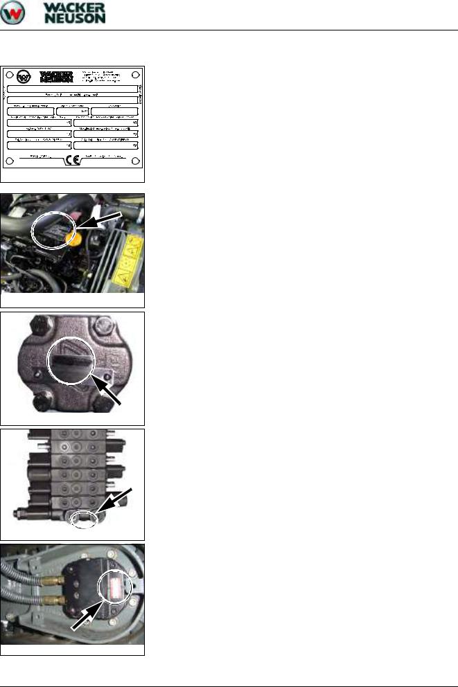
1.4 |
Labels |
Fig. 1: Type label (symbolic representation)
Fig. 2: Diesel engine type label
Fig. 3: Hydraulic pump type label
Fig. 4: Main valve block type label
Fig. 5: Traveling drive type label
Serial number
The serial number is located on the type label.
The serial number is also stamped on the machine chassis.
Refer to the Operator’s Manual of the machine for more information.
Diesel engine type label
The type label (arrow) is located on the cylinder-head cover (engine).
Hydraulic pump type label
The type label (arrow) is located on the hydraulic pump housing.
Main valve block type label
The type label (arrow) is located on the lower side of the main valve block.
Traveling drive type label
The type label (arrow) is located on the traveling drive.
SHB 803 en – Edition 2.4 * 803s110.fm |
1-5 |

Operation
Swivel unit type label
The type label (arrow) is located on the swivel unit.
Fig. 6: Swivel unit type label
1-6 |
SHB 803 en – Edition 2.4 * 803s110.fm |

Operation
1.5 Machine overview (up to serial no. AI00966)
1 |
Boom light |
7 |
1 |
2 |
3 |
2 |
Boom |
|
|
|
|
3 |
Stick |
|
|
|
|
|
|
|
|
|
|
4 |
Track |
|
|
|
|
|
|
|
|
|
|
5 |
Travel gear |
|
|
|
|
6 |
Stabilizer blade |
|
|
|
|
|
|
|
|
|
|
7 |
Handhold |
|
|
|
|
|
|
|
|
|
|
8 |
Lifting eye for loading/tying down the machine |
9 |
|
|
|
9 |
Engine cover |
|
|
|
|
|
|
|
|
|
|
10 |
Storage bin for Operator’s Manual |
|
|
|
|
|
|
|
|
|
|
11 |
Lock lever |
8 |
|
|
|
12 |
Track tensioner |
|
|
8 |
|
|
|
|
|
|
|
4 |
5 |
12 |
6 |
3 |
2 |
7 |
11 |
10
|
|
|
8 |
6 |
4 |
5 |
12 |
Fig. 7: Machine outside views |
|
|
|
|
|
|
|
|
|
|
|
SHB 803 en – Edition 2.4 * 803s110.fm |
|
|
1-7 |

Operation
1.6 Machine overview (from serial no. AI00967)
|
|
|
1 |
2 |
3 |
1 |
Boom light |
14 |
|
|
|
2 |
Boom |
|
|
|
|
|
|
|
|
||
|
|
13 |
|
|
|
3 |
Stick |
|
|
|
|
|
|
|
|
|
|
4 |
Track |
7 |
|
|
|
5 |
Travel gear |
|
|
|
|
|
|
|
|
||
|
|
|
|
|
|
6 |
Stabilizer blade |
11 |
|
|
|
|
|
|
|
|
|
7 |
Handhold |
|
|
|
|
|
|
|
|
||
8 |
Lifting eye for loading/tying down the |
|
|
|
|
machine |
|
|
|
|
|
|
|
|
|
|
|
9 |
Engine cover |
9 |
|
|
|
|
|
|
|
|
|
10 |
Storage bin for Operator’s Manual |
|
|
|
|
|
|
|
|
||
11 |
Lock lever |
|
|
|
|
|
|
|
|
|
|
12 |
Track tensioner |
|
|
|
|
|
|
|
|
|
|
13 |
ROPS rollbar (option) |
|
|
|
8 |
14 |
Shatter protection (option) |
8 |
|
|
|
|
|
|
|||
|
|
|
|
|
|
3 |
2 |
7 |
14 |
11 |
4 |
5 |
12 |
6 |
|
|
|
|
10
|
|
|
8 |
6 |
4 |
5 |
12 |
Fig. 8: Machine outside views |
|
||
|
|
|
|
|
|
|
|
1-8 |
|
|
SHB 803 en – Edition 2.4 * 803s110.fm |

Operation
1.7 Control stand overview (up to serial no. AI00814)
3 |
9 |
5
8 |
4 |
|
6 |
2 |
7 |
Pos. Designation
1Operator seat
2Upper carriage lock
3Engine cover lock
4Preheating start switch
5Stabilizer blade/telescopic undercarriage lever
6Stabilizer blade/telescopic travel gear changeover lever
7Auxiliary hydraulics
8Engine cover
9Handhold
SHB 803 en – Edition 2.4 * 803s110.fm |
1-9 |

Operation
17
16
15
14
18
13
12
11
10
Pos. Designation
10Boom swivel/auxiliary hydraulics pedal
11Footrest
12Control lever lock
13Throttle
14Control lever (left)
15Drive lever (left)
16Drive lever (right)
17Control lever (right)
18Indicators
1-10 |
SHB 803 en – Edition 2.4 * 803s110.fm |
Operation
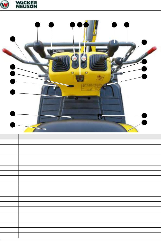
1.8 Control stand overview (from serial no. AI00815)
14 |
13 |
15 |
18 |
16 |
17 |
9 |
12
5
11 |
11 |
|
|
19 |
7 |
|
|
6 |
|
3 |
2 |
|
|
1 |
8 |
|
Pos. Designation
1Operator seat
2Upper carriage lock
3Engine cover lock
4Starter
5Stabilizer blade/telescopic travel gear lever
6Stabilizer blade/telescopic travel gear changeover lever
7Boom swivel pedal
8Engine cover
9Handhold
10Auxiliary hydraulics pedal
11Footrest
12Lock lever
13Throttle
14Control lever (left)
15Drive lever (left)
16Drive lever (right)
17Control lever (right)
18Display element
19Lever for switching over hammer/grab operation (option)
SHB 803 en – Edition 2.4 * 803s110.fm |
1-11 |

Operation
1.9 Display elements (overview)
20 |
21 |
22 |
23 |
24
Pos. Designation
20Indicator light (red) – alternator charge function
21Indicator light (red) – engine oil pressure
22Indicator light (red) – coolant temperature
23Indicator light (yellow) – fuel gage
24Hour meter
1-12 |
SHB 803 en – Edition 2.4 * 803s110.fm |

Operation
1.10 Engine compartment overview (up to serial no. AI00814)
25 |
27 |
26 |
32 |
28 |
29 |
30 |
31 |
Pos. Designation
25Air filter
26Throttle cable
27Fuel filter
28Swivel unit
29Thermostat
30Filler neck
31Coolant filler inlet
32Coolant reservoir
SHB 803 en – Edition 2.4 * 803s110.fm |
1-13 |

Operation
1.11 Engine compartment overview (from serial no. AI00815)
33 |
34 |
35 |
40 |
36 |
37 |
38 |
39 |
Pos. Designation
33Air filter
34Fuel filter
35Throttle cable
36Swivel unit
37Thermostat
38Filler neck
39Coolant filler inlet
40Coolant reservoir
1-14 |
SHB 803 en – Edition 2.4 * 803s110.fm |
Technical data

Technical data
2 |
Technical data |
|
|
2.1 |
Chassis |
|
|
|
|
Sturdy steel sheet chassis, rubber-mounted engine |
|
2.2 |
Engine |
|
|
|
|
|
|
|
|
Engine |
Model 803 |
|
|
Product |
Yanmar diesel engine |
|
|
|
|
|
|
Type |
3TNV70-VNS |
|
|
|
|
|
|
Design |
Water-cooled 4 stroke diesel engine |
|
|
|
|
|
|
Number of cylinders |
3 |
|
|
|
|
|
|
Fuel injection system |
Indirect injection |
|
|
|
|
|
|
Aspiration |
Natural aspiration |
|
|
|
|
|
|
Cooling system |
Water-cooled/blowing fan |
|
|
|
|
|
|
Lubrication system |
Force-feed lubrication with trochoidal pump |
|
|
|
|
|
|
Displacement |
854 cm³ (52.1 in³) |
|
|
|
|
|
|
Nominal bore and stroke |
70 x 74 mm (2.75 x 2.91") |
|
|
|
|
|
|
Output |
9.6 kW (12.9 hp) at 2100 rpm |
|
|
|
|
|
|
Max. torque |
51.5 Nm (38 ft lbs) at 1500 rpm |
|
|
|
|
|
|
Max. engine speed without load |
2270 +/− 25 rpm |
|
|
|
|
|
|
Idling speed |
1300 +/− 25 rpm |
|
|
|
|
|
|
Valve clearance (intake = outlet) |
0.15 – 0.25 mm/(0.006 – 0.01") cold |
|
|
|
|
|
|
Compression |
32.4 +/− 1 bar (469.9 +/− 15 psi) at 250 rpm |
|
|
|
|
|
|
Engine oil pressure |
2.9 – 4.4 bar (42 – 64 psi) at rated output |
|
|
|
|
|
|
Pressure switch for engine oil pump |
0.5 +/− 0.1 bar (7.25 +/− 1.45 psi) |
|
|
|
|
|
|
Thermostat opening temperature |
69.5 – 72.5 °C (157 – 163 °F) |
|
|
|
|
|
|
Thermal switch |
107 – 113 °C (225 – 235 °F) |
|
|
|
|
|
|
Firing order |
1 – 3 – 2 – 1 |
|
|
|
|
|
|
Direction of rotation |
Anticlockwise |
|
|
(as seen from the flywheel) |
|
|
|
|
|
|
|
|
|
|
|
Starting aid |
Glow plugs (preheating time 4 seconds) |
|
|
|
|
|
|
Specific fuel consumption |
272 g/kWh (lb/hph) |
|
|
|
|
|
|
Max. engine droop |
By about 90 rpm |
|
|
(all 2 pumps under full load) |
|
|
|
|
|
|
|
|
|
|
|
Exhaust values according to |
EPA TIER IV final (up to 2012) |
|
|
|
|
2-2 |
SHB 803 en – Edition 2.4 * 803s210.fm |

Technical data
Engine |
Model 803 |
|
Product |
Yanmar diesel engine |
|
|
|
|
Type |
3TNV74F-SNNS |
|
|
|
|
Design |
Water-cooled 4 stroke diesel engine |
|
|
|
|
Number of cylinders |
3 |
|
|
|
|
Fuel injection system |
Indirect injection |
|
|
|
|
Aspiration |
Natural aspiration |
|
|
|
|
Cooling system |
Water-cooled/blowing fan |
|
|
|
|
Lubrication system |
Force-feed lubrication with trochoidal pump |
|
|
|
|
Displacement |
993 cm³ (60.6 in3) |
|
Nominal bore and stroke |
74 x 77 mm (2.9 x 3.0 in) |
|
|
|
|
Output |
11.5 kW at 2500 rpm |
|
(15.4 hp/2,500 rpm) |
||
|
||
Max. torque |
53 Nm at 1800 rpm |
|
(39 ft.lbs/1800 rpm) |
||
|
||
Max. engine speed without load |
2675 +/− 25 rpm |
|
(2,675 +/− 25 rpm) |
||
|
||
Idling speed |
1300 +/− 25 rpm |
|
(1,300 +/− 25 rpm) |
||
|
||
Valve clearance (intake = outlet) |
0.15 – 0.25 mm/(0.006 – 0.01") cold |
|
|
|
|
Compression |
32.4 +/− 1 bar (469.9 +/− 15 psi) at 250 rpm |
|
|
|
|
Engine oil pressure |
3 – 4.5 bar (43.5 – 65.3 psi) at rated output |
|
|
|
|
Pressure switch for engine oil |
0.5 +/− 0.1 bar (7.25 +/− 1.45 psi) |
|
pump |
||
|
||
|
|
|
Thermostat opening temperature |
71 °C (160 °F) |
|
|
|
|
Thermal switch |
107 °C (230 °F) |
|
|
|
|
Firing order |
1 – 3 – 2 – 1 |
|
|
|
|
Direction of rotation |
Anticlockwise |
|
(as seen from the flywheel) |
||
|
||
|
|
|
Starting aid |
Glow plugs (preheating time 4 seconds) |
|
|
|
|
Specific fuel consumption |
279 g/kWh (lb/hph) |
|
|
|
|
Max. engine droop (all 2 pumps |
By about 110 rpm |
|
under full load) |
||
|
||
|
|
|
Exhaust values according to |
EPA TIER IV final (from 2012) |
|
|
|
SHB 803 en – Edition 2.4 * 803s210.fm |
2-3 |

Technical data
Fuel injection pump
|
Type |
|
|
Design |
In-line pump |
|
|
|
|
Injection pressure |
118 – 128 bar (1711 – 1856 psi) |
|
|
|
|
Engine speed control |
Mechanical |
|
|
|
|
Lubrication system |
Force-feed engine oil lubrication |
|
|
|
Engine capacities |
|
|
|
|
|
|
Capacities |
Model 803 |
|
Fuel tank |
7 l (1.85 gal) |
|
|
|
|
Engine oil (max./effect.) |
2.8 l/1.3 l (0.74/0.34 gal) |
|
|
|
|
Coolant (with radiator) |
2.9 l (0.77 gal) |
|
|
|
|
Coolant reservoir |
1.1 l (0.29 gal) |
|
|
|
|
Overview of capacities – see Fluids and lubricants on page 3-2 |
|
Engine tightening torques |
|
|
|
|
|
|
Tightening torques |
Model 803 |
|
Cylinder-head bolt1 |
54 – 58 Nm (M9x1.25) (40 − 43 ft lbs) |
|
Connecting rod bearing screw1 |
22.6 − 27.5 Nm (M7x1.0) (16.6 − 20.3 ft lbs) |
|
Main bearing screw |
75.5 – 81.5 Nm (M10x1.25) (55.7 – 60 ft lbs) |
|
|
|
|
Flywheel screw |
80.4 – 86.4 Nm (M10x1.25) (59.3 – 63.7 ft lbs) |
|
|
|
|
1. Screws must be oiled! |
|
2.3 Hydraulic system |
|
|
|
|
|
|
Hydraulics |
Model 803 |
|
Pump (Tier IV final up to 2012) |
Twin gear pump 2 x 5 cm³ (2 x 0.3 in³/rev) |
|
|
|
|
Flow rate (Tier IV final up to 2012) |
2 x 11.35 l/min at 2270 rpm |
|
(2 x 3 gal/min at 2270 rpm) |
|
|
|
|
|
Pump (Tier IV final from 2012) |
Twin gear pump 2 x 4 cm³ (2 x 0.24 in³/rev) |
|
|
|
|
Flow rate (Tier IV final from 2012) |
2 x 10.7 l/min at 2675 rpm |
|
(2 x 2.8 gal/min at 2675 rpm) |
|
|
|
|
|
Control valve |
9 sections |
|
|
|
|
Main pressure limiting valve for pumps |
170 +/− 3 bar (2465.64 +/− 44 psi) |
|
P1, P2 |
|
|
|
|
|
|
|
|
Secondary pressure limiting valve |
70 -0/+0.5 bar (1015.3 -0/+7 psi) at 11.5 l/min (3 |
|
for swivel unit |
gal/min) |
|
|
|
|
Secondary pressure limiting valve, stick |
250 +/−5 bar (3625.9 +/−72.5 psi) |
|
|
|
|
Hydraulic reservoir capacity |
13.8 l (3.6 gal) |
|
|
|
2-4 |
SHB 803 en – Edition 2.4 * 803s210.fm |

|
|
|
Technical data |
|
|
|
|
Auxiliary hydraulics oil flow |
|
||
|
|
|
P1 + P2 (l/min / gal/min) |
|
|
Pressure (bar/psi) |
|
|
12.5/181.3 |
22/5.8 |
|
|
|
|
|
37.8/548.2 |
20.8/5.5 |
||
|
|
|
|
|
50/725.2 |
20.4/5.4 |
|
|
|
|
|
|
79/1145.8 |
19.7/5.2 |
|
|
|
|
|
140/2030.5 |
18.5/4.8 |
||
|
|
|
|
|
160/2320.6 |
10.5/2.7 |
|
|
|
|
|
|
168/2436.6 |
5/1.3 |
|
|
|
|
|
|
|
|
|
Notice!
Output indications for auxiliary hydraulics with unpressurized return line
2.4 Travel gear and swivel unit
Travel gear/swivel unit |
Model 803 |
|
Travel speeds |
1.82 kph (1.13 mph) |
|
|
|
|
Hill climbing ability |
30°/58 % |
|
(no longer than 3 minutes) |
||
|
||
|
|
|
Track width |
180 mm (7.09'') |
|
|
|
|
No. of track rollers on either side |
2 |
|
|
|
|
Ground clearance |
132 mm (5.2'') |
|
|
|
|
Ground pressure |
0.24 kg/cm² (3.4 psi) |
|
|
|
|
Upper carriage swivel speed |
8 rpm |
|
|
|
2.5 Stabilizer blade
|
Stabilizer blade |
Model 803 |
|
Width (folded in/out) |
700/860 mm (27.55"/33.85") |
|
|
|
|
Height |
198 mm (7.8'') |
|
|
|
|
Max. lift over/under subgrade |
197/174 mm (7.76"/6.85") |
|
|
|
Screwable hose burst valve |
|
|
Location |
Thread |
Gap dimension |
Stabilizer blade |
3/8" |
0.3 mm (0.012'') |
|
|
|
SHB 803 en – Edition 2.4 * 803s210.fm |
2-5 |

Technical data
2.6 Electrical system
Fuses behind the right-hand trim
F1
F3 F2
Fig. 9: Fuses (up to serial number
WNCE0801CPAL0050)
Electrical system |
|
|
||
|
|
|
|
|
Dynamo |
|
|
12 V 20 A |
|
|
|
|
|
|
Starter |
|
|
12 V 1.1 kW (1.5 hp) |
|
|
|
|
|
|
Battery |
|
|
12 V 30 Ah |
|
|
|
|
|
|
Socket |
|
|
For 12 V power outlet, for example; 15 A max. |
|
|
|
|
|
|
|
|
|
||
Fuse no. |
Rated current (A) |
Protected circuit |
||
|
|
|
||
F1 |
40 A |
Main fuse: air-pressure sensor/output adaptation |
||
(Yanmar 3TNV74F-SNNS) |
||||
|
|
|||
F2 |
10 A |
Fuse: relay, indicator, cutoff solenoid |
||
|
|
|
||
F3 |
10 A |
Fuse: horn, working light 12 V power outlet (up to |
||
serial number WNCE0801CPAL0050, travel signal |
||||
|
|
(option) |
||
F4 |
10 A |
12 V power outlet (from serial number |
||
WNCE0801TPAL0051) |
||||
|
|
|||
F1
F4 F3 F2
Fig. 10: Fuses (from serial number WNCE0801TPAL0051)
2-6 |
SHB 803 en – Edition 2.4 * 803s210.fm |

Technical data
Relays behind the right-hand trim
 K8
K8
K9
K7
Fig. 11: Relays
Relay no. |
Protected circuit |
|
|
K 7 |
Starting relay |
|
|
K 8 |
Cutoff solenoid time lag relay 1s |
|
|
K 9 |
Cutoff solenoid switching relay |
|
|
Fuses and relays with Dual Power option
F4
F1  F3
F3
 F2
F2
K9 K7
Fig. 12: Fuses and relays with Dual Power option
If the machine is equipped with the Dual Power option, the fuses and relays are located under the base plate.
Fuse no. |
Rated current (A) |
Protected circuit |
|
|
|
|
|
F1 |
40 A |
Main fuse: air-pressure sensor/output adaptation |
|
(Yanmar 3TNV74F-SNNS) |
|||
|
|
||
F2 |
10 A |
Fuse: relay, indicator, cutoff solenoid |
|
|
|
|
|
F3 |
10 A |
Fuse: horn, working light 12 V power outlet (up to |
|
serial number WNCE0801CPAL0050, travel signal |
|||
|
|
(option), battery control (Dual Power option) |
|
F4 |
10 A |
12 V power outlet (from serial number |
|
WNCE0801TPAL0051) |
|||
|
|
|
Relay no. |
Protected circuit |
|
|
|
|
|
|
K 7 |
Starting relay |
|
|
|
|
|
|
K 8 |
Cutoff solenoid time lag relay 1s |
|
|
|
|
|
|
K 9 |
Cutoff solenoid switching relay |
|
K8 |
|
|
|
K 116 |
Battery control |
||
|
|||
|
|
|
Fig. 13: Relay K8
SHB 803 en – Edition 2.4 * 803s210.fm |
2-7 |

Technical data
2.7 Noise levels
Sound power level |
Model 803 |
Sound power level (LWA)1 |
93 dB (A) |
Operator-perceived sound pressure level (LPA)2 |
77 dB (A) |
Uncertainty (KPA) 3 |
1.2 dB (A) |
1.ISO 6395 (EC Directives 2000/14/EC and 2005/88/EC)
2.EN ISO 4871 (EC Directives 2000/14/EC and 2005/88/EC)
3.ISO 6394 (EC Directives 84/532/EEC, 89/514/EEC, 95/27/EEC)
Notice!
Measurements performed on asphalted surface.
2.8 Vibration
Vibration
Effective acceleration value for the upper extremities of the |
< Trigger value |
body (hand-arm vibration) |
< 2.5 m/s2 |
Effective acceleration value for the body (whole-body vibration) |
< 0.5 m/s2 |
Vibration values indicated in m/s².
2.9 Coolant compound table
Outside temperature |
|
|
Coolant |
|
|
Water |
Anticorrosion agent |
Antifreeze agent |
|||
|
|||||
Up to °C (°F) |
% by |
cm³/l / (in3/gal) |
% by volume |
% by volume |
|
volume |
|||||
|
|
|
|
||
-37 (-34.6) |
50 |
10 (2.6) |
1 |
50 |
|
|
|
|
|
|
|
Use the 1:1 concentration for warm outside temperatures, too:
Protection against corrosion, cavitation and deposits
Do not mix the coolant with other coolants.
Machine filled at the factory with Eurolub SF D12 coolant (ethylene glycol basis).
2-8 |
SHB 803 en – Edition 2.4 * 803s210.fm |
Loading...