

Page 1
Installation instructions
1064373-R03
1
1
«Front loader» washing machine
One-family household
For Service and Spare Part Information please contact: V-ZUG AUSTRALIA Pty. Ltd. Tel+61732096822
The appliance should be installed by qualified personnel only.
Each step must be carried out and checked in full in the order specified.
Validity
These installation instructions apply to the models: 11021, 11023, 11025
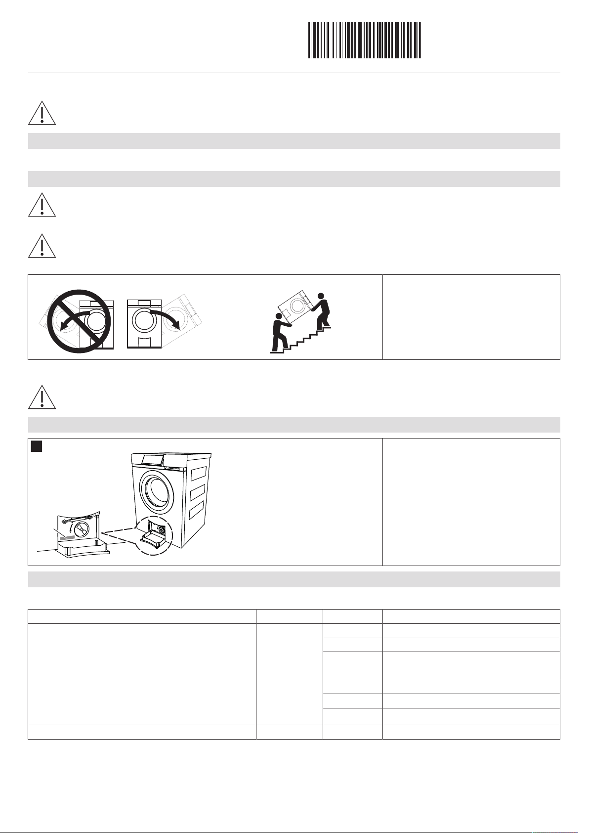
Transport
If the weight of the appliance is greater than your lifting capacity, the appliance must be transported by several
people or using a transport aid. The weight of the appliance is given on the appliance packaging and in the operating
instructions.
Transport the appliance in an upright position only! Transporting it in any other position will cause damage. When
carried carefully without being shaken, the appliance may be tilted a maximum of 90° to the right (viewed from the
front).
1064373-R03
06/08/2019
Applicable only to model 11025:
In the event that the appliance is tilted during transportation or installation it must not be put into operation for 2
hours.
Identification plate
▸ Open the drain tray below the appliance
door (see «1. Opening the appliance
door»).
– Identification plate 1
Installation accessories supplied
The necessary installation accessories are located in the washing drum and in the appliance packaging.
Designation Article no. Number See installation step
Installation set, incl.:
▪ Rubber stopper
▪ Screw material (3 each of screws, washers,
rawlplugs)
▪ Drain hose
▪ Wire hose clamp
▪ Hose support
Installation plate (incl. double-sided adhesive tape) W40653 1 4. Positioning the installation plate
W41152 1
2 2. Removing the transport lock
1 4. Positioning the installation plate
1 6. Plumbing in
1 6. Plumbing in
1 6. Plumbing in
1
Page 2
Installation instructions
1064373-R03
1
A
C
2
A
B
3
4
C
D
5
1
2
D
D
2
F
1
4
G
3
F
E
F
«Front loader» washing machine
One-family household
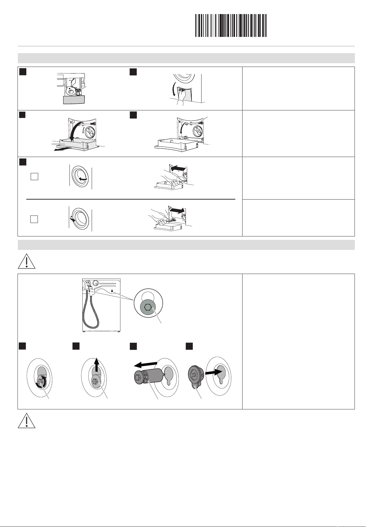
1. Opening the appliance door (without power)
1064373-R03
06/08/2019
▸ Remove liquid-detergent flap A from de-
tergent dispenser drawer B.
▸ Open drain tray C with liquid-detergent
flap A.
▸ Fold drain tray C right down and remove
it.
▸ Remove emergency door release tool D
from bracket.
Variant 1: Left-hand hinge door:
▸ Insert tool D into blue emergency door
release and pull to the left.
– The appliance door opens.
2. Removing the transportation lock
The transport locks F on the rear side have to be removed before using the appliance for the first time.
Variant 2: Right-hand hinge door:
▸ Insert tool D into blue emergency door
release and pull to the right.
– The appliance door opens.
▸ Remove the hexagon head screws E of
the transport locks F using a 10 mm ring
or open-end wrench.
▸ Push up and pull out the transport lock F.
▸ Plug the holes with the rubber stoppers
G.
Risk of soiling!
Failure to plug the holes with the rubber stoppers can result in error messages. Insert the rubber stoppers and prevent soiling
in the appliance.
2
Page 3
Installation instructions
1064373-R03
180°
180°
957 957
4
2
3
1
213
80
72
160
45
595
33
625
850
(125)
500
577
500 50
(42)
15
84.5
725
550 458 104
Open door 1059*
Left-hand opening Right-hand opening
Open door 1059*
«Front loader» washing machine
One-family household
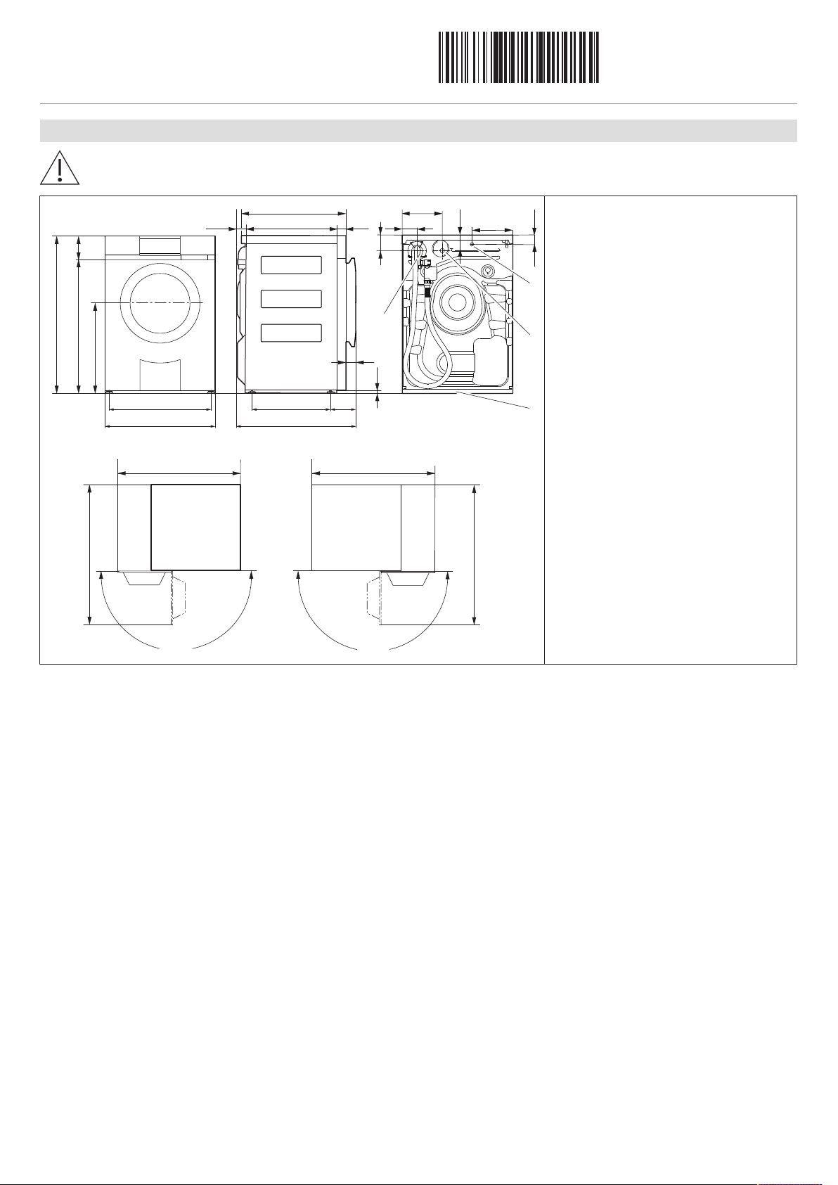
3. Dimensions
The stated dimensions do not include distances from walls. To prevent disturbing noise and vibration the appliances
must not come into contact with the surrounding walls of their installation location.
1064373-R03
06/08/2019
▸ Cold water connection 1: inlet hose with
Aquastop, length: 1.25 m, G¾"
▸ Drain hose connection 2: length: 1.5 m,
pumping height for drain pump: 1.2 m
▸ Electrical connection cable outlet 3:
length: 1.8 m
▸ Installation plate 4
* In order that the detergent dispenser drawer can be used without obstruction and be taken out for cleaning, the clearance space must
be observed across the entire front of the appliance.
3
Page 4

Installation instructions
1064373-R03
1
E
D
45
3×
1
2
2
ø6
1
45
5
595
510
5
555
D
«Front loader» washing machine
One-family household
4. Positioning the installation plate
General tips
Use the installation plate supplied to install the appliance. It fixes the appliance in position, and is for use with both
free-standing appliances and appliances positioned in a niche.
The use of an unsuitable installation plate or a soft, sound-insulating underlay can affect the proper functioning of the appliance.
In case of underfloor heating, do not drill holes in the floor! Adhere installation plate into place!
1064373-R03
06/08/2019
▸ Fold out spacers D in order to keep dis-
tance to the back wall.
Free-standing position
If a tumble dryer and a washing machine are positioned side by side, keep a distance of min. 5mm between the installation plates and to the walls at the side and min. 45mm to the back wall. The installation plates for the washing
machine and tumble dryer are the same.
Variant 1: Without underfloor heating:
▸ Fasten installation plate to the floor with
3screws.
▸ Dampen mounting slots E with water to
make the appliance easier to push in.
Variant 2: With underfloor heating:
▸ Holes must not be drilled in the floor if
the room has underfloor heating. The
installation plate must be adhered to the
floor.
▸ Dampen mounting slots E with water to
make the appliance easier to push in.
▸ Fold out spacers D in order to keep dis-
tance to the back wall.
▸ Dimensions 45 and 555 only apply if no
plumbing fittings are to be installed behind the appliance.
4
Page 5

Installation instructions
1064373-R03
605
1
2
45
≥860
≥605
≥
10
0
≥100
3
A
C
D
=
50
A
≥
60
5
A
D
=
83
A
≥
64
5
1
2
E
B
B
1
L
«Front loader» washing machine
One-family household
Positioning in a niche
1064373-R03
06/08/2019
▸ Centre the installation plate in the niche.
▸ Distance to the back wall: ≥45mm
▸ Cut-out for lateral connections (left or
right): ≥100 × 100mm
▸ Niche height for washing machine:
≥860mm
Variant 1: Niche front B and appliance front
C are flush:
▸ Niche depth A≥605 mm
▸ Installation offset for installation plate
D=50mm.
5. Levelling
To ensure fault-free operation, the appliance must stand level with all 4 feet firmly on the installation plate and not
wobble.
Variant 2: Niche front B and appliance door
E are flush:
▸ Niche depth A≥645 mm
▸ Installation offset for installation plate
D=83mm.
▸ Roughly adjust the height of the front and
rear adjuster feet using socket wrench
(size 10). Height adjustment: ≤14mm
(1.5mm per turn)
▸ Use a spirit level L to level the appliance.
▸ Slide the appliance onto the installation
plate.
▸ Finely adjust the height of the front ad-
juster feet.
▸ Use a spirit level L to level the appliance.
– The appliance must not wobble.
5
Page 6

Installation instructions
1064373-R03
1
A
Hose clamp
Drain hose A
Rubber connection
1.5 m
ø internal 21.5 mm
ø external 28 mm
≤1200
≥350
B
A
≤700
A
B
«Front loader» washing machine
One-family household
6. Plumbing in
Local water authority regulations must be observed.
Any old water supply and drain hoses must always be replaced with new hoses.
Water inlet
Only cold water G¾” permitted, possible pressure range: 0.1–1.0 MPa (1–10 bar).
The appliance must not be connected to a mixer tap or a continuous flow boiler!
1064373-R03
06/08/2019
Preferred alignment for Aquastop valve
blockA (sound-optimized installation):
▸ The tap seal seat must be clean and flat.
▸ Install hose without kinking or twisting it.
▸ Check for leaks.
Water outlet
When installing the drain hose, protect it against damage and kinks!
Installing the drain hose Work steps
▸ For drainage into fixed upright outflow
pipe, shorten drain hose A to necessary
length.
▸ For drainage into a bath tub or sink, etc.,
drain hose A cannot be shortened!
Drainage into an open-top fixed upright
outflow pipe
Drainage into a bath tub or sink, etc. Work steps
▸ For all connection types, mount the hose
support B.
▸ For drainage into a bath tub or sink, etc.,
secure the hose end with hose support
B.
Max. pumping height: 1200mm Max. pumping height: 700mm
6
Page 7

Installation instructions
1064373-R03
«Front loader» washing machine
One-family household
7. Electrical connections
Electrical connections
Electrical connections must be carried out by qualified personnel in accordance with the guidelines and standards
for low-voltage installations and the specifications of the local electricity supply companies.
A plug-in appliance may only be connected to a socket outlet with earthing contact, installed according to specifications. An
all-pole mains isolating device with 3 mm contact opening should be provided in the house wiring system. Switches, plug and
socket devices, circuit breakers and fusible cut-outs which are accessible after installation and which have all-poles switching
are permissible as isolating devices. Effective earthing and separately installed neutral and earth conductors ensure safe and
fault-free operation. After installation, live parts and cables with basic insulation must not be accessible. Check old installations.
▸ The appliance is designed for use up to a max. altitude of 2000 m above sea level.
▸ Refer to the identification plate for information on the required mains voltage, current type and fuse protection.
The mains plug must not be cut off.
1064373-R03
06/08/2019
Connection cable
Valid for all washing machines and tumble dryers in the Adora, AdoraWash and AdoraDry model range.
The mains cable may only be replaced by the manufacturer, its Customer Services or a similarly qualified person.
Error messages «U1»
Disconnect the appliance from the mains and control the wiring.
7
Page 8

Installation instructions
1064373-R03
1
2
3 4
5 6
7
F
8 9
+
2min
Yes
10
11
11
1 ×
12
13
5s
+
+
14
15
2h
11025
11021, 11023
«Front loader» washing machine
One-family household
8. Performing the stability check
Strong vibrations are deliberately produced during the stability check in order to check that the appliance is standing firmly on the
ground.
1064373-R03
06/08/2019
▸ Insert plug into mains socket or turn on at wall
switch.
▸ Remove drum contents, close appliance door.
▸ Turn on water tap.
▸ Close the appliance door.
▸ Select language.
▸ Touch .
– In the display appears: «Transport locks re-
moved?»
▸ Remove transport locks F (see section 2).
▸ Touch .
– In the display appears: «Stability check»
▸ Touch .
– The stability check starts.
– Spinning is carried out and in the display ap-
pears: «Creating unbalanced load, please
wait…»
▸ After 2 minutes, in the display appears: «Check sta-
bility»
▸ Realign adjuster feet if necessary.
▸ The appliance must stand level with all 4 feet firmly
on the installation plate and not wobble.
▸ The user must carry out a visual and haptic assess-
ment as the appliance cannot detect or display the
set-up.
▸ Touch the button.
– In the display appears: «Create unbalanced
load finishing…»
– The spinning is finished, the appliance is
drained.
▸ Check stability and realign adjuster feet if neces-
sary.
▸ Repeat stability check if necessary: Depress the
, and buttons simultaneously for 5
seconds.
▸ For model 11025, wait 2 hours.
▸ Touch any button.
▸ Follow the instructions in the display and set the
time and date.
8
 Loading...