

VXL Instruments TL120 User Manual
TL120 Series Thin Client Laptop
Hardware Installation Guide
The TL120 package consists of several items, which are listed below:
TL120 Thin Cl ient Laptop
Power Adapter DC 20V/3.25A
This manual
Power cord applicable to your country ( Optional )
We use our best possible efforts to ensure that all the items that
should be in the package are in fact there. However if something is
missing we do sincerely apologise and request you to either return the
product to where you obtained it from, or contact VXL at any of their
sales offices for assistance.
In order that the TL120 performs in accordance with expectations,
This guide covers the installation of the hardware, and does not cover
the configuration of Software. For software configuration refer
(http://www.vxl.net
Precautions
While installing the TL120 hardware in your network infrastructure you
must ensure some simple precautions:
• Protect yourself from the heat generated by the AC
• Prevent your computer from getting wet.
• To avoid spills and the danger of electric shock, keep
• Do not drop, bump, scratch, twist, hit, vibrate, push, or
• Use a quality carrying case that provides adequate
• Do not pack your computer in a tightly packed suitcase or
• Always place the unit on a flat surface.
Page: 1
).
adapter.
When the AC adapter is connected to an electrical outlet
and your computer, it generates heat.
Extended contact with your body, even through clothing,
may cause a skin burn.
liquids away from your computer.
place heavy object on your computer, display or external
device.
cushioning and protection.
bag
Setting up the TL120
The following steps will ensure that your new TL120 is perfectly set up
and operational.
1. Unpack the unit taking care not to drop the product while
removing from the packaging.
2. Please retain the packaging for possible future use.
3. You will need the following items:
a. Power Adapter
b. Power cord
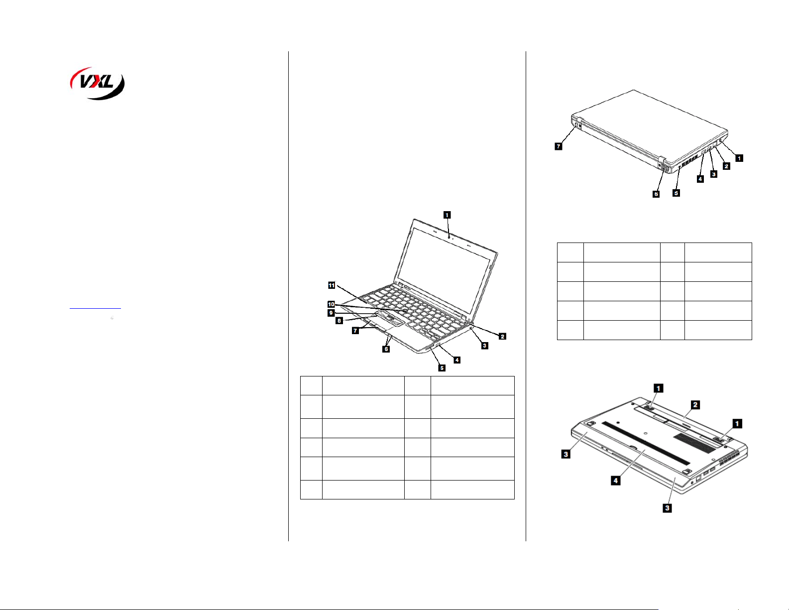
4. Place the TL120 on the desktop as shown fig (1).
1. It is now time for you to connect the power cord and
network to the TL120 in order to make it fully operational.
Fig 1- Front View
Ref Components Ref Components
Integrated Camera
1
( Optional)
2
Power Switch 8 Touch pad
3&4
USB 9 Track Point button
4 in 1 Media card reader
5
slot
6
Power status indicators 11
7
Touch pad buttons
10 Track Point pointing stick
Build-in digital
microphone
Page:2
Fig 2 - Rear View
Ref Components Ref Components
1 Combo audio jack 4 Security key hole
2 RJ-45 ( Ethernet) port 5
3 USB 6
4 HDMI port
External monitor
connector
DC Power
connector
Fig 3- Bottom View
Page:3
Ref Components Ref Components
1 Battery pack latch 3
2 Battery pack 4 Bottom door
Build – in stereo
speaker
Powering the TL120
Press the power button as indicated in the Fig.1 to
Power on the TL120.
Reporting a problem
1. Go to http://www.vxl.net/Support/Online-support.aspx
Select “Click Here” from the desire support required
i.e. (RMA Request or Report a problem) OR
Visit a URL https://support.vxl.net/
2. Provide your e-mail ID.
3. Click on "Submit Request"
4. Fill all the Information along with the Problem description,
and Click “Save”
Your call is registered and you will receive an e-mail with ticket no.
You can reply to this mail for further communication.
Checking the status of your ticket
1. Go to http://www.vxl.net/Support/Online-support.aspx
Select “Click Here” from the desire support required
i.e. (RMA Request or Report a problem) OR
visit a URL https://support.vxl.net/
2. Provide your e-mail ID.
3. Click on View My Request.
Regulatory Certifications
RoHS
© 2011 VXL Instruments Limited
600011053230 Z00
Page:4
 Loading...