

Page 1
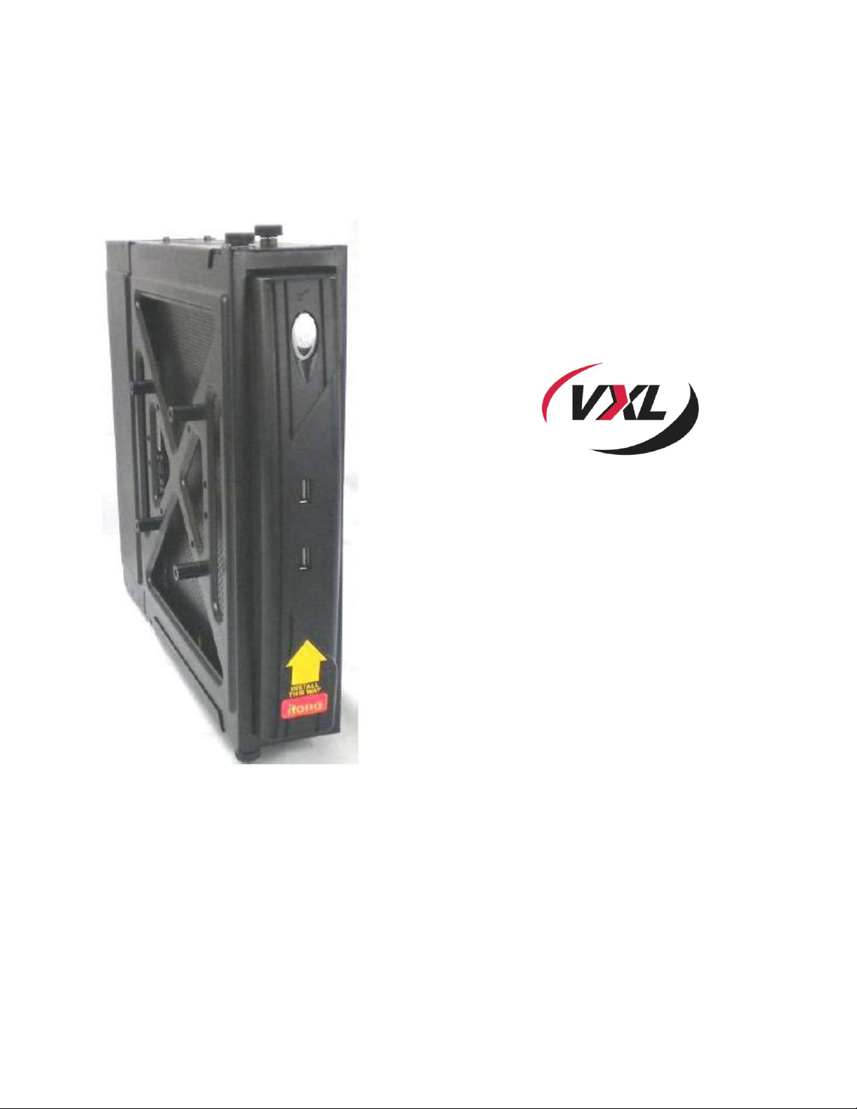
Itona TC72yy
Service Manual
Page 2

Copyright © 2004-2012 VXL Instruments Limited. All Rights Reserved
Information in this document is subject to change without notice and does not represent a
commitment on the part of the manufacturer. No part of this guide may be reproduced or transmitted
in any form or means, electronic or mechanical, including photocopying and recording, for any
purpose, without the express written permission of the manufacturer.
Every effort has been made to make this guide as complete and as accurate as possible, but no
warranty or fitness is implied. The authors and the publisher shall have neither responsibility nor
liability to any person or entity with respect to loss or damages arising from the use of information
contained in this guide. This disclaimer does not apply in countries where such provisions are
inconsistent with local law.
All Trademarks are acknowledged.
Last Updated: September, 2012
Version: TC72yy/SM-36-12
VXL Instruments Ltd.,
House of Excellence,
No. 17, Electronics City,
Hosur Road,
Bangalore
www.vxl.net
– 560 100, INDIA
Page 3

Table of Contents
1 Tools Required 1
2 Thin Client Bracket 3
Removing the thin client from the bracket 3
3 Removing the Side Cover 4
Fixing the Bracket and Side Cover 4
4 Replacing RAM 6
5 Replacing Flash 8
6 Replacing the Motherboard 10
7 Removing the Power Supply Unit 13
Page 4

Warning and Caution Statements
Warning: It is best to wear an electrostatic discharge (ESD) cuff when handling electronic
components (Motherboard, RAM and Power Supply).
Warning: Please ensure that the power supply is switched off before unplugging the power supply
connector from the motherboard.
Caution: Memory modules have a foolproof insertion design. A memory module can be installed in
only one direction. If you are unable to insert the module, please reverse the direction.
Page 5
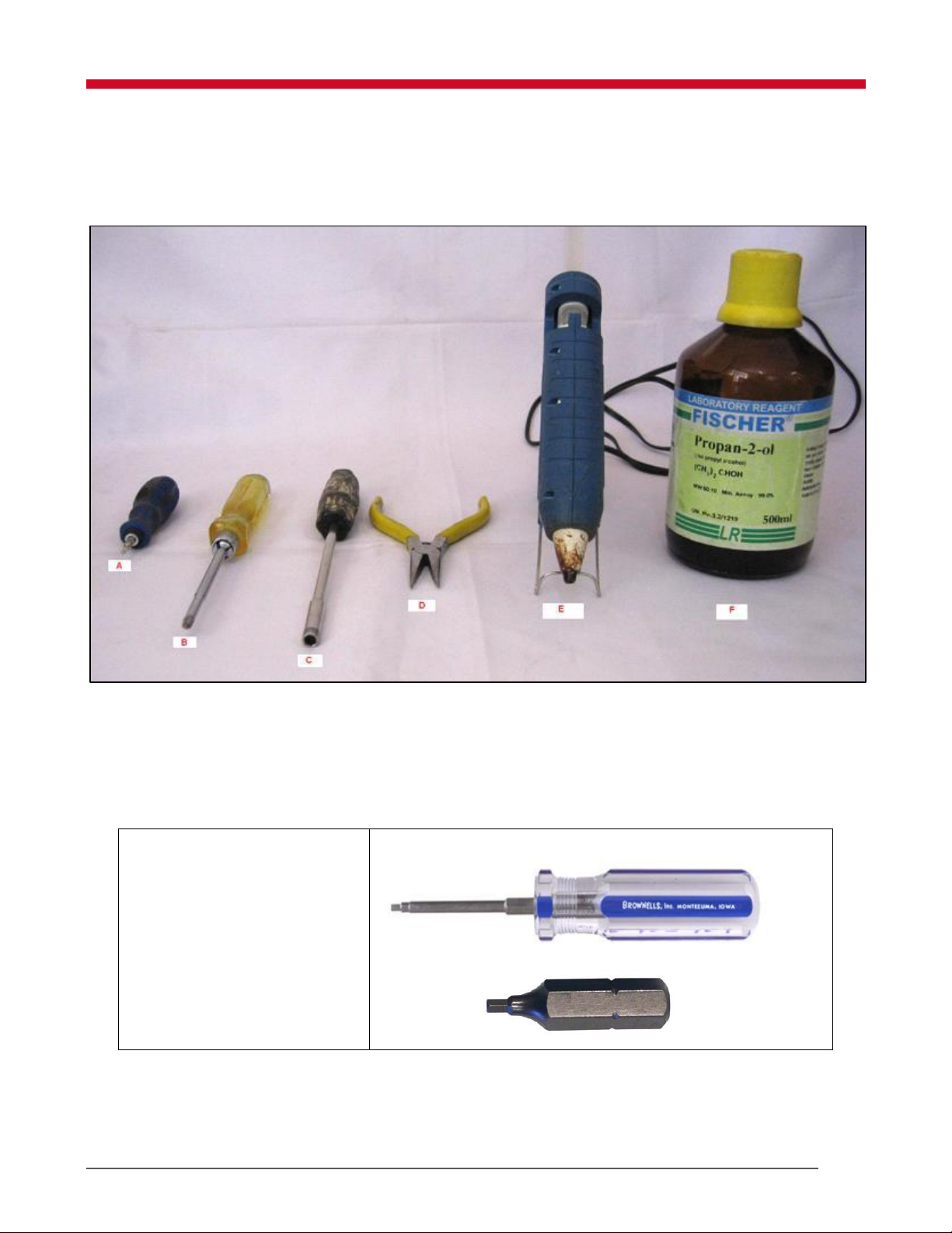
A. ALLEN Hex HEAD
2.0mm Screwdrivers
A. HEX Screwdriver E. Hot Glue Gun with rod
B. Star Screwdriver F. Isopropyl Alcohol ((CH3)2 CHOH)
C. Nut Driver
D. Nose pliers
1 Tools Required
The tools required for servicing the Itona TC72yy Thin Client are shown in Figure 1.
Figure 1: Tools Required
1 Tools Required
Page 6
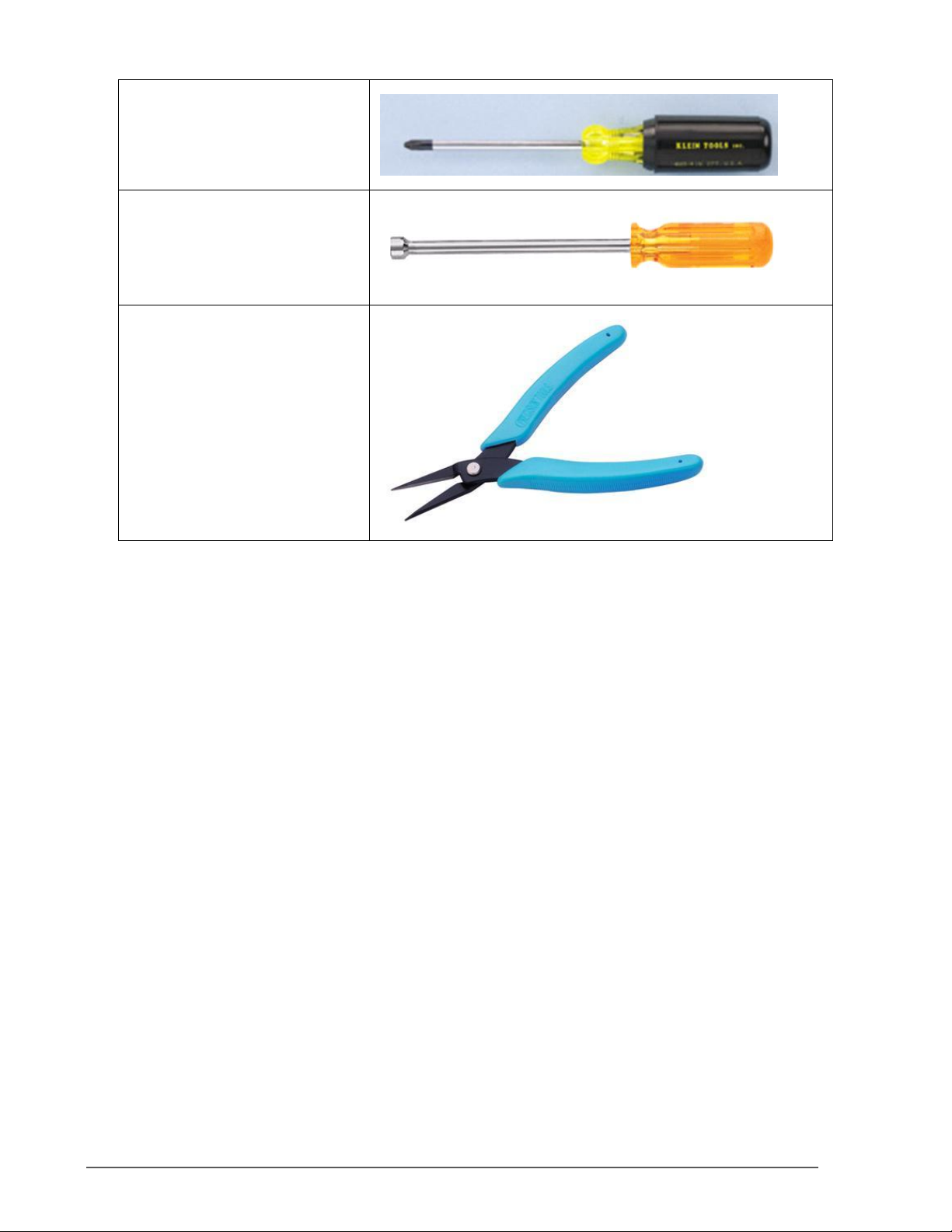
B. Phillips screw driver
C. Hex Nut driver 5.0 mm
D. Nose pliers with spring
Tools Required 2
Page 7
2 Thin Client Bracket
Removing the thin client from the bracket
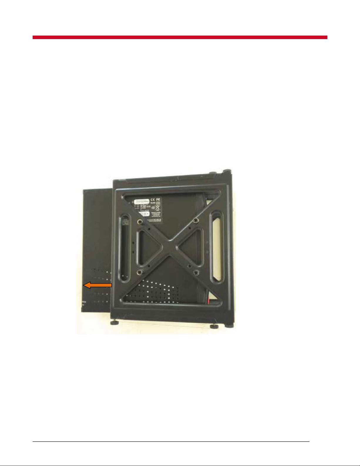
The procedure to remove the thin client from the bracket is explained in this section.
To remove the thin client from the bracket:
1. Turn off the power to the client.
2. Remove all the cables connected to the client.
3. Unscrew the thumbscrews provided at the bottom of the bracket.
4. Pull the thin client carefully out of the bracket as shown in Figure 2.
Figure 2: Thin Client Bracket
3 Thin Client Bracket
Page 8
3 Removing the Side Cover
The procedure to remove the side cover of the client is explained in this section.
To remove the and side cover:
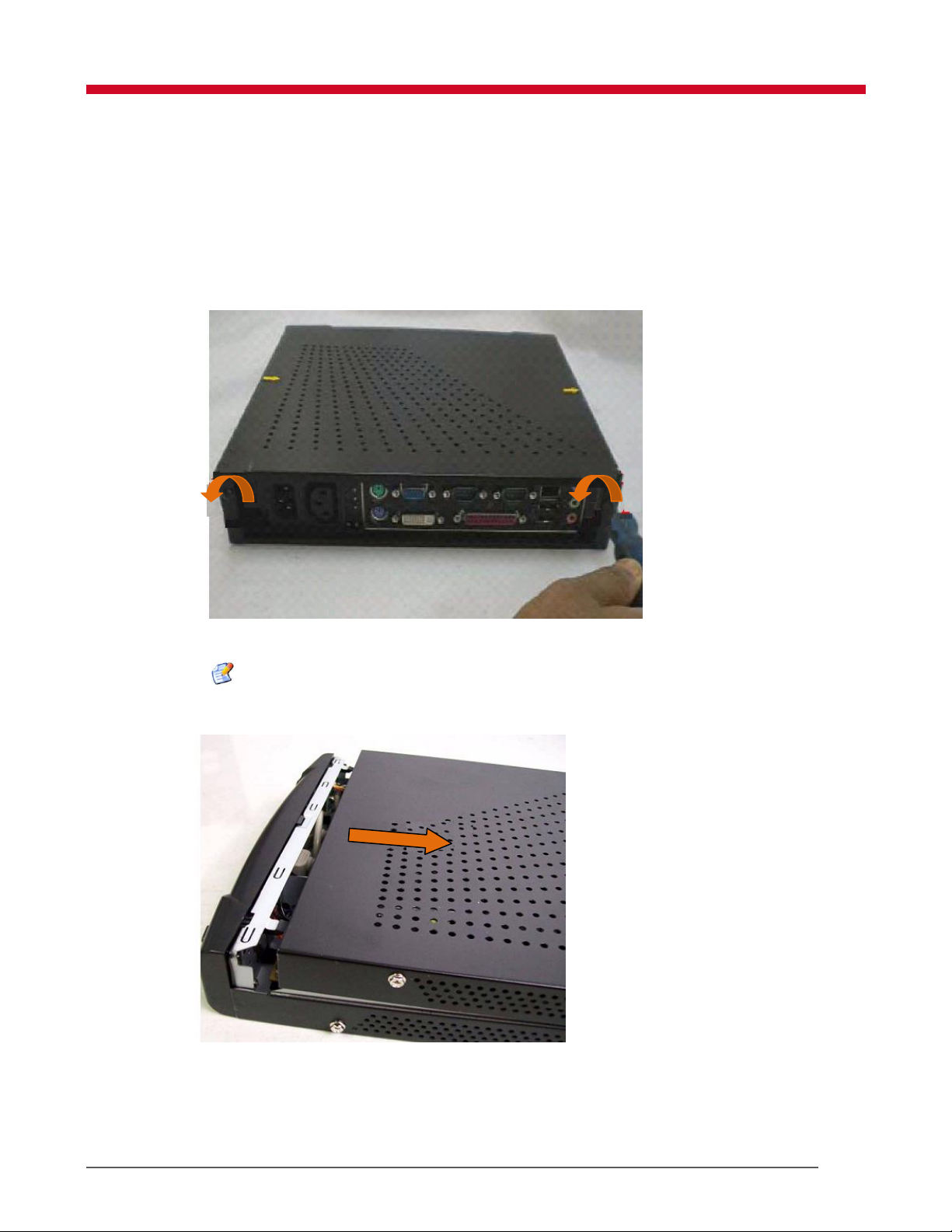
1. Using the star screwdriver (Item B in Figure 1) unscrew the 2 screws as shown in Figure
3
Figure 3: Side Cover Screws
Note: Retain the screws for future use.
2. Slide the side cover and remove it as shown in Figure 4.
Figure 4: Removing Side Cover
Fixing the Bracket and Side Cover
To fix the side cover and power adapter:
Removing the Side Cover 4
Page 9

1. Gently press the side cover downwards.
2. Using the star screwdriver (Item B in Figure 1) tighten the two screws holding the side
cover.
3. Push the thin client into the bracket, fasten the thumb screws.
4. Connect the power adapter in the power input socket.
5. Switch on the power to the client.
5 Removing the Side Cover
Page 10
4 Replacing RAM
To replace RAM:
1. Remove the power adapter and side cover . For more information see Removing the Side Cover
on page 4.
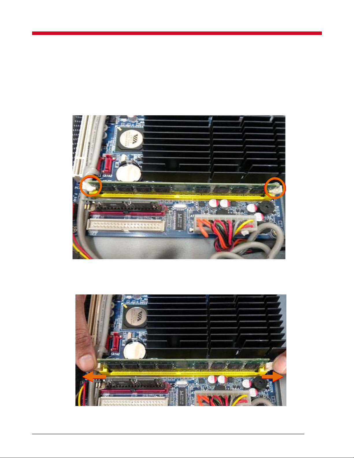
2. Apply isopropyl alcohol on the glue holding the RAM, pull the glue out using the nose pliers.
Figure 5: RAM Socket Clips
3. Remove the existing RAM from the socket by unlocking the holders and pulling it
outwards.
Figure 6: RAM Slot
Replacing RAM 6
Page 11

4. Place the new RAM on the socket.
Note: Ensure that the new RAM is of the same dimensions as the existing RAM.
5. Slide the RAM downwards until the clip at each end of the socket lock into position.
Note: You will hear a distinctive click sound, indicating that the module is correctly
locked into position.
6. Fix the side cover and power adapter. For more information see Removing the Side
Cover on page 4.
7 Replacing RAM
Page 12
5 Replacing Flash
To replace Flash:
1. Remove the power adapter and side cover. For more information see Removing the Side
Cover on page 4.
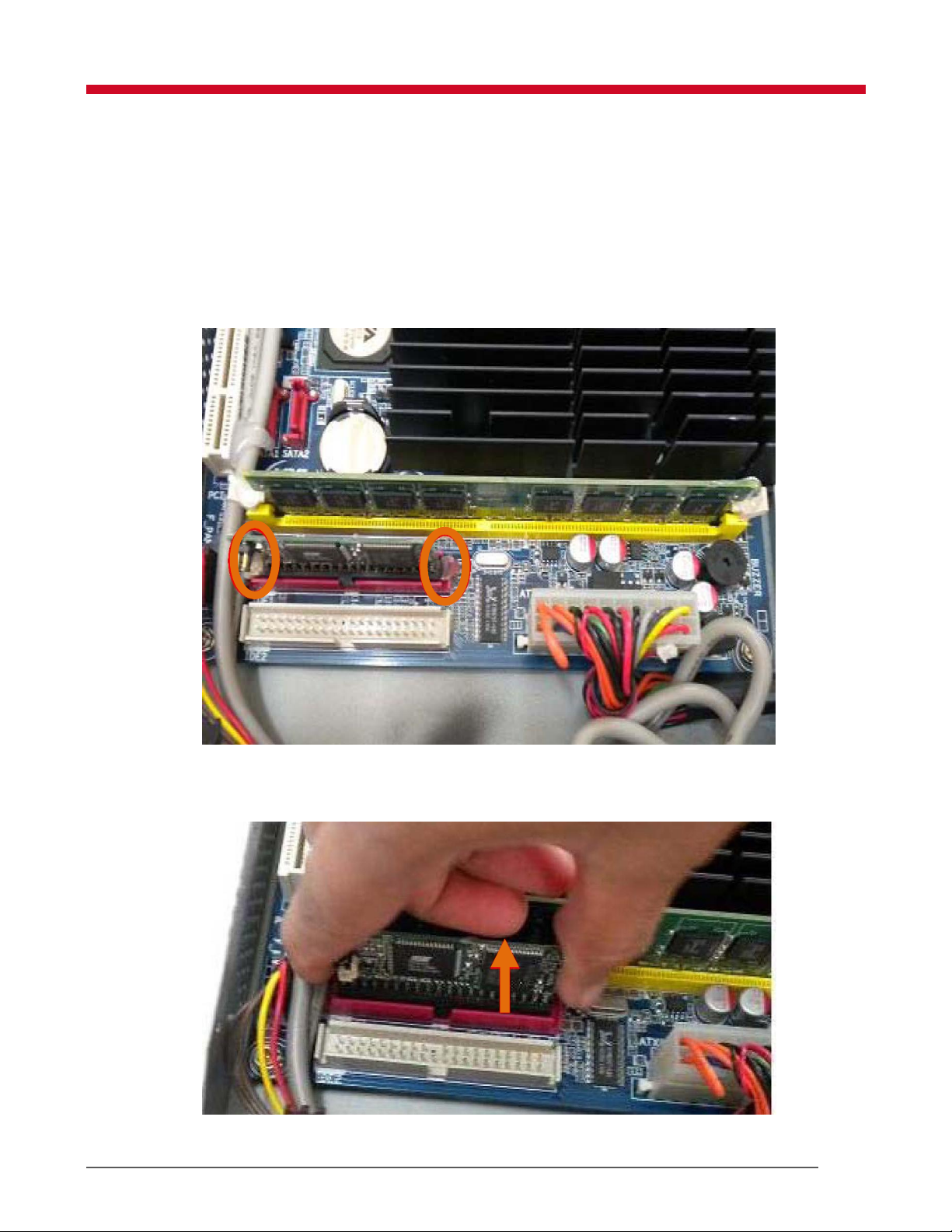
2. Apply isopropyl alcohol on the glue holding the flash, pull the glue out using the nose
pliers.
Figure 7: Removing Glue
3. Gently pull the IDE flash up from the socket, as shown in Figure 8.
Figure 8: IDE Flash
Replacing Flash 8
Page 13

4. Place the new flash in the socket and press it downwards.
Note: Ensure that the new flash is of the same dimensions as the earlier one and has the
correct software image installed on it.
5. Fix the side cover and power adapter.
9 Replacing Flash
Page 14
6 Replacing the Motherboard
To replace the motherboard:
1. Remove the power adapter and side cover. For more information see Removing the Side
Cover on page 4
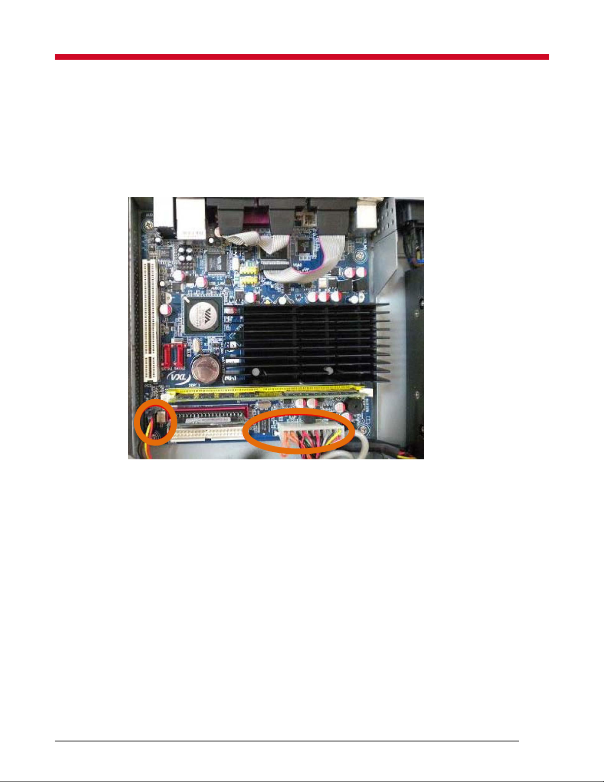
2. Unplug the ATX power and LED switch connectors as shown in Figure 9.
Figure 9: ATX and LED Connectors
3. Unplug the USB and VGA and COM port cables as shown in the Figure 10.
Replacing the Motherboard 10
Page 15
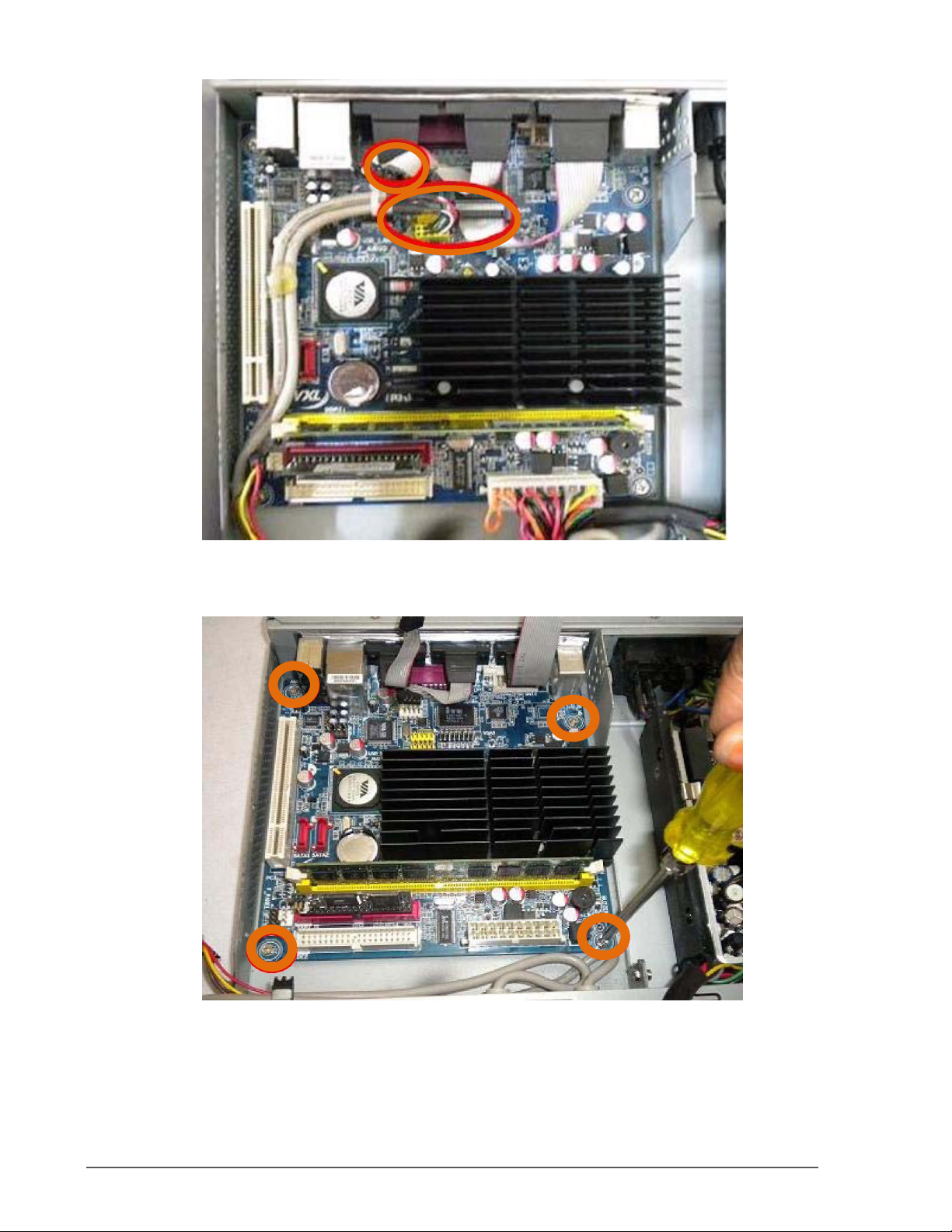
Figure 10: USB, VGA and COM port cables
4. Remove the motherboard as shown in Figure 11.
Figure 11: Motherboard Screws
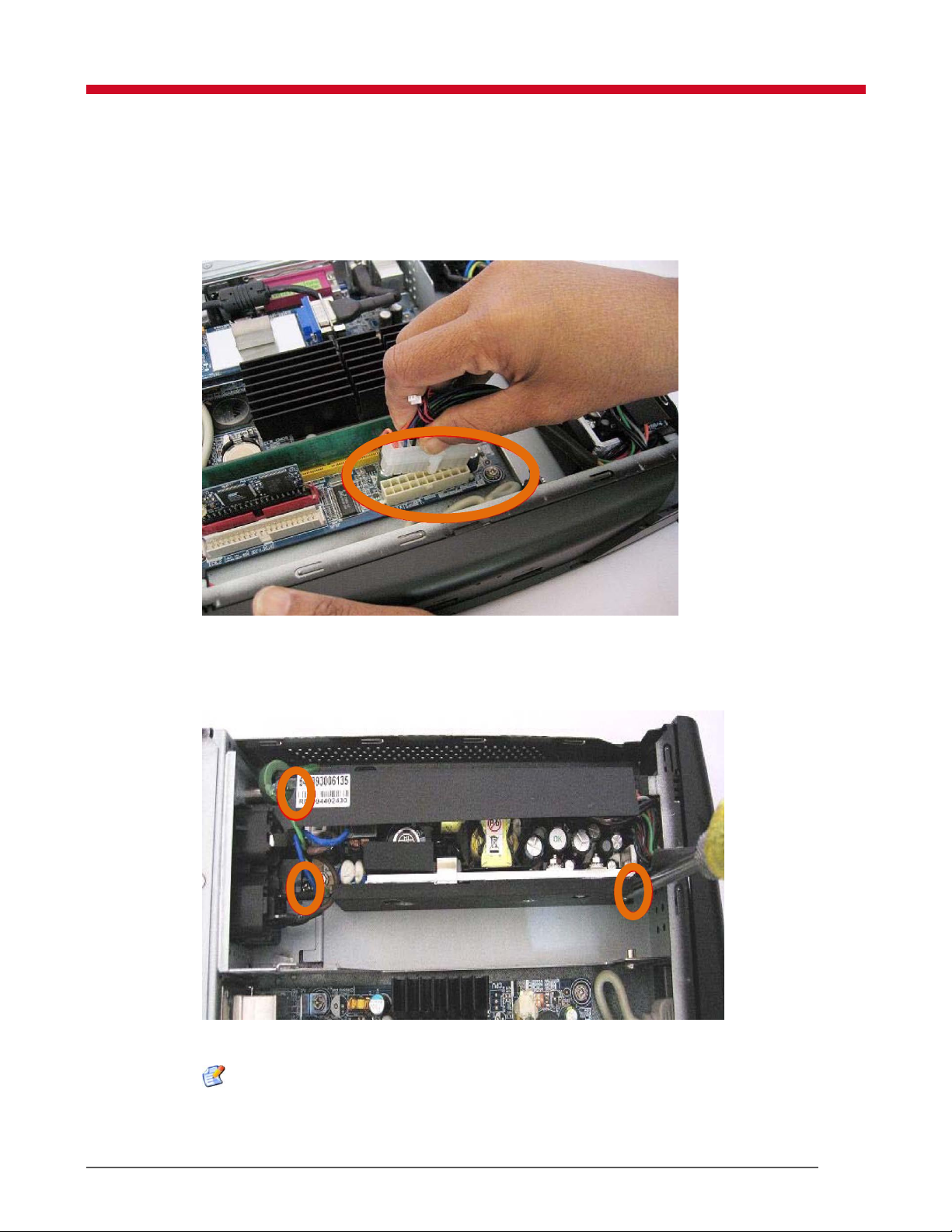
5. Remove the motherboard from the cabinet as shown in Figure 12.
11 Replacing the Motherboard
Page 16
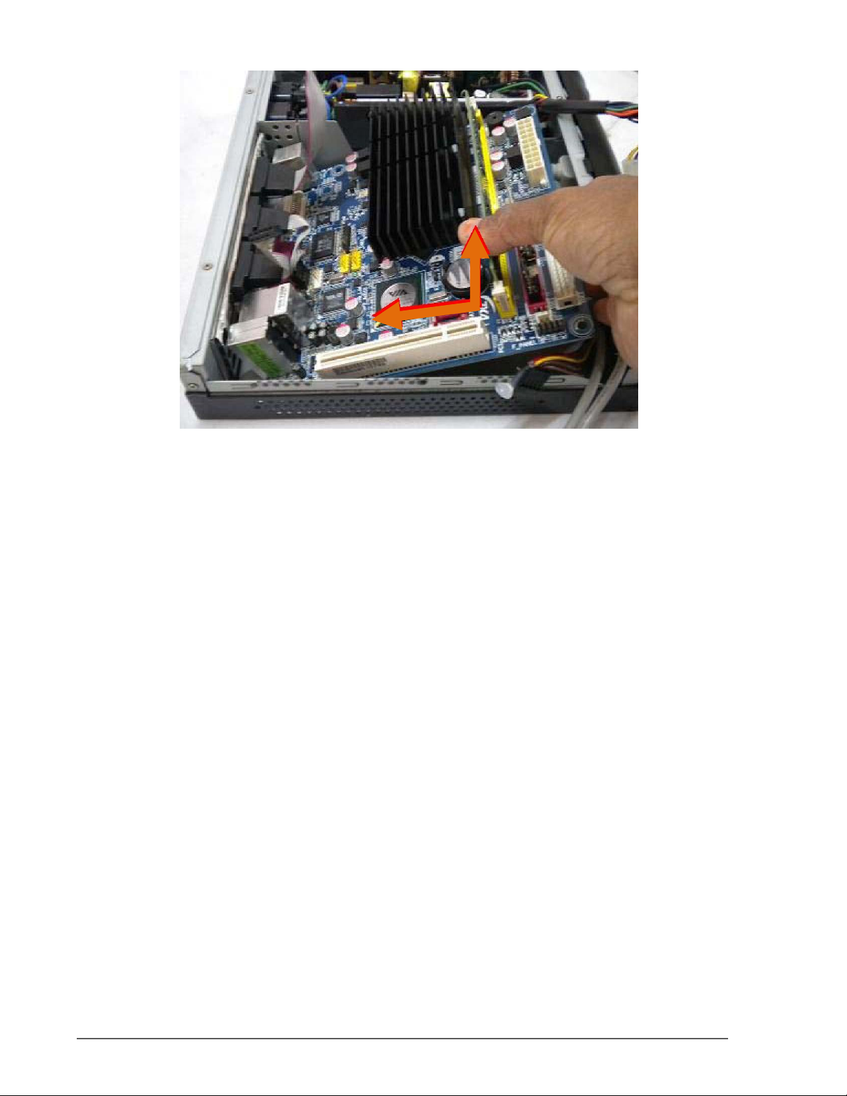
Figure 12: Removing Motherboard
6. Replace the existing motherboard with a new motherboard.
7. Using the star screwdriver ( Item B in Figure 1) fix the motherboard using the four available
screws.
8. Fix the side cover and power adapter.
Replacing the Motherboard 12
Page 17
7 Removing the Power Supply Unit
To replace the power supply unit:
1. Disconnect the ATX power supply cable as shown in the Figure 13.
Figure 13: ATX Power Supply
2. Using the star screwdriver ( Item B in Figure 1), unscrew the three screws holding the power
supply unit as shown in Figure 14: AC
Figure 14: AC Power Unit Screws
Note: Do not remove the earth connection (The green yellow wire).
3. Remove the power supply unit outward as shown in Figure 15.
13 Removing the Power Supply Unit
Page 18
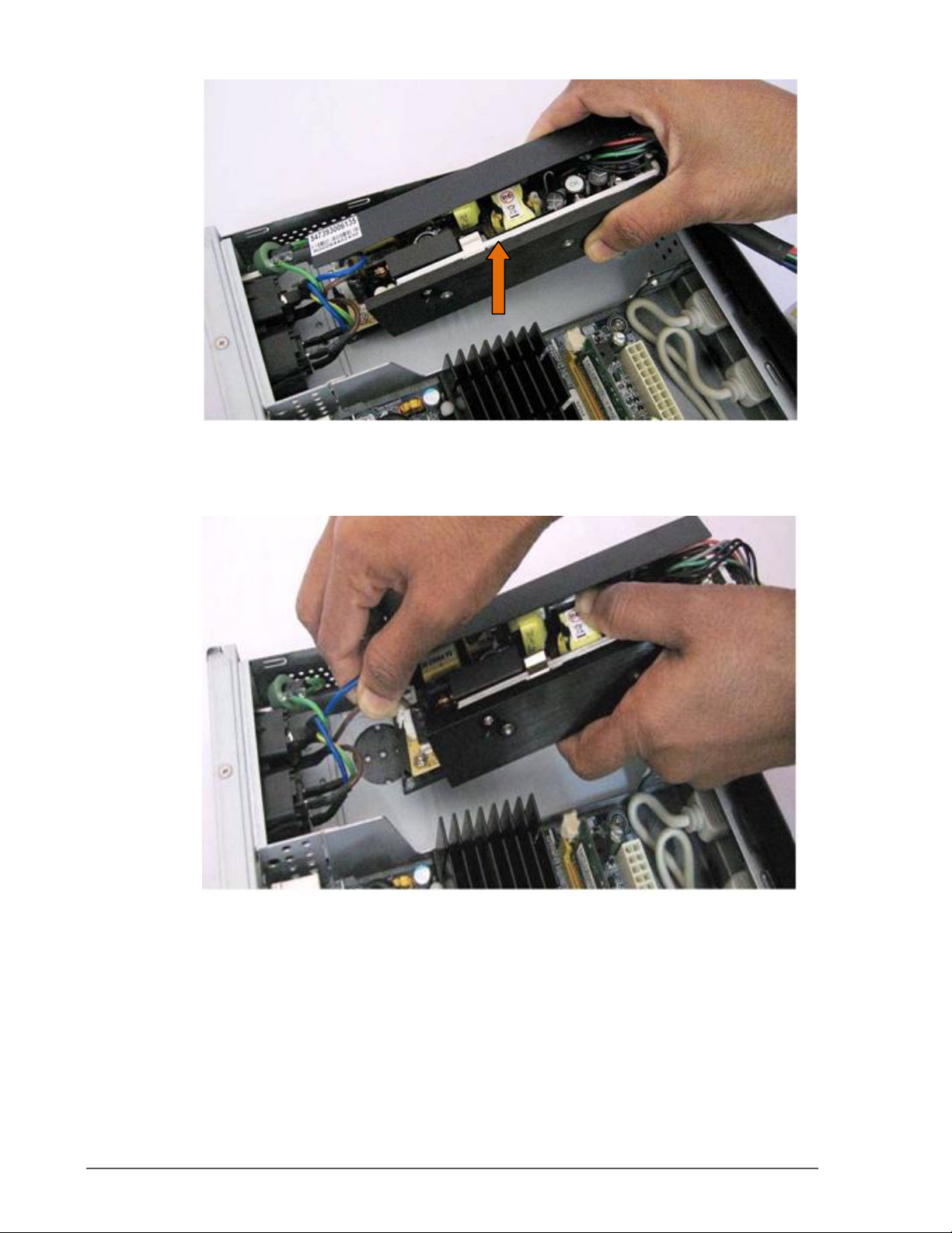
Figure 15: Power Supply Unit
4. Remove the wires connected to the power supply unit. You may replace a new unit in its
place.
Figure 16: Power Supply Unit Wires
Removing the Power Supply Unit 14
 Loading...