

VXL Instruments TC15yy User Manual
TC15yy
Service Manual

Copyright © 2004-2013 VXL Instruments Limited. All Rights Reserved.
Information in this document is subject to change without notice and does not represent a commitment on
the part of the manufacturer. No part of this guide may be reproduced or transmitted in any form or means,
electronic or mechanical, including photocopying and recording, for any purpose, without the express written
permission of the manufacturer.
Every effort has been made to make this guide as complete and as accurate as possible, but no warranty or
fitness is implied. The authors and the publisher shall have neither responsibility nor liability to any person or
entity with respect to loss or damages arising from the use of information contained in this guide. This
disclaimer does not apply in countries where such provisions are inconsistent with local law.
All Trademarks are acknowledged.
Last Updated: September, 2012.
Version: TC15yy/SM-37-12.
VXL Instruments Ltd.,
House of Excellence,
No. 17, Electronics City,
Hosur Road,
Bangalore
www.vxl.net
– 560 100, INDIA.

Table of Contents
1 Tools Required .......................................................................................................................................1
2 Pedestal and Side Cover ........................................................................................................................3
Removing the Pedestal and Side Cover .................................................................................................. 3
Fixing the Pedestal and Side Cover ........................................................................................................ 4
3 Replacing RAM .......................................................................................................................................5
4 Replacing Flash ......................................................................................................................................7
5 Replacing Wireless LAN .........................................................................................................................8
6 Replacing the Motherboard ................................................................................................................... 10

Warning and Caution Statements
Warning: It is best to wear an electrostatic discharge (ESD) cuff when handling electronic
components (Motherboard, RAM and Power Supply).
Warning: Please ensure that the power supply is switched off before unplugging the power supply
connector from the motherboard.
Caution: Memory modules have a foolproof insertion design. A memory module can be installed in
only one direction. If you are unable to insert the module, please reverse the direction
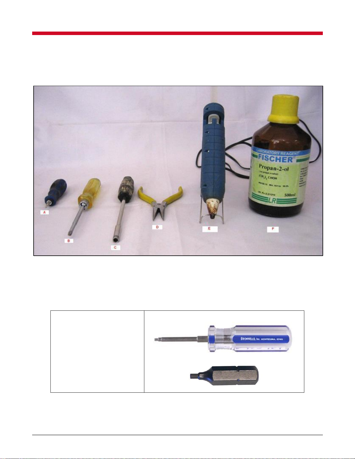
A. ALLEN Hex HEAD 2.0mm
Screwdrivers
A. HEX Screwdriver E. Hot Glue Gun with rod.
B. Star Screwdriver F. Isopropyl Alcohol ((CH3)2 CHOH)
C. Nut Driver
D. Nose pliers
1 Tools Required
The tools required for servicing the TC 15yy series Thin Client are shown in Figure 1.
Figure 1: Tools Required
Tools Required 1
 Loading...