

Page 1
VG40 SHOWN
SERVICE MANUAL
GAS BRAISING PANS
(30 & 40 GALLON)
VG30 ML-126847
VG40 ML-126848
- NOTICE This Manual is prepared for the use of trained Vulcan Service
Technicians and should not be used by those not properly
qualified. If you have attended a Vulcan Service School for this
product, you may be qualified to perform all the procedures
described in this manual.
This manual is not intended to be all encompassing. If you have
not attended a Vulcan Service School for this product, you should
read, in its entirety, the repair procedure you wish to perform to
determine if you have the necessary tools, instruments and skills
required to perform the procedure. Procedures for which you do
not have the necessary tools, instruments and skills should be
performed by a trained Vulcan Service Technician.
Reproduction or other use of this Manual, without the express
written consent of Vulcan, is prohibited.
For additional information on Vulcan-Hart Company or to locate an authorized parts
and service provider in your area, visit our website at www.vulcanhart.com.
A product of VULCAN-HART LOUISVILLE, KY 40201-0696
F25121(February 2003)
Page 2

GAS BRAISING PANS
TABLE OF CONTENTS
GENERAL ................................................................................ 3
Installation, Operation and Cleaning ......................................................... 3
Introduction ............................................................................ 3
Control Panel ...................................................................... 3
Model Designations ................................................................. 3
Tools................................................................................. 3
Specifications ..........................................................................3
REMOVAL AND REPLACEMENT OF PARTS .................................................... 4
Covers and Panels ...................................................................... 4
Power Supply Box Components ............................................................ 5
Temperature Controller .................................................................. 5
Pan Position/Down Limit Switch ............................................................ 6
Thermocouple Probe .................................................................... 8
DC Lift Motor .......................................................................... 9
Gear Reducer ......................................................................... 10
Gas Combination Valve ................................................................. 11
Pilot Burner ........................................................................... 12
Runner Tube .......................................................................... 12
Main Burners ......................................................................... 13
Lid Springs ........................................................................... 13
SERVICE PROCEDURES AND ADJUSTMENTS ................................................. 15
Temperature Controller Calibration ........................................................ 15
Temperature Controller Test ............................................................. 16
Thermocouple Test .................................................................... 16
Spark Ignition Test ..................................................................... 17
Pilot Burner Flame Adjustment............................................................ 18
Flame Sense Current Test ............................................................... 19
Ignition Control Module Test .............................................................. 19
Gas Manifold Pressure Adjustment ........................................................ 20
Main Burners ......................................................................... 21
Inspection ........................................................................ 21
Air Shutter Adjustment .............................................................. 21
DC Motor Controller Test ................................................................ 22
Pan Position/Down Limit Switch Adjustment ................................................. 22
Lid Spring Tension Adjustment............................................................ 23
ELECTRICAL OPERATION .................................................................. 25
Component Function ................................................................... 25
Component Location ................................................................... 26
Ignition Control Module .................................................................. 27
Sequence of Operation .................................................................. 28
Schematic Diagram .................................................................... 30
TROUBLESHOOTING ...................................................................... 31
Gas Heating (Manual Lift or Motorized Lift Option) ............................................ 31
Motorized Lift Option Only ............................................................... 32
CONDENSED SPARE PARTS LIST ........................................................... 32
© VULCAN 2003
F25121 (February 2003) Page 2 of 32
Page 3
GAS BRAISING PANS
GENERAL
INSTALLATION, OPERATION
AND CLEANING
Refer to the Installation & Operation Manual for
specific instructions.
INTRODUCTION
The tilting braising pan (skillet) is a versatile piece of
cooking equipment. It can be used to stew, simmer,
steam, sear, pan fry, grill or saute food products over
an evenly distributed heating surface. Once the
product is fully cooked, the pan can be tilted for ease
of product removal.
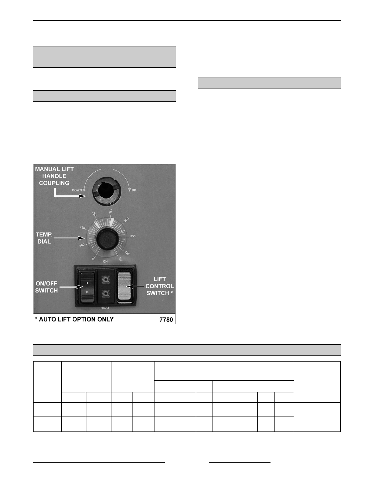
Control Panel
Model Designations
! VG30 - 30 gallon capacity
! VG40 - 40 gallons capacity
TOOLS
Standard
! Standard set of hand tools.
! VOM with an AC current tester and DC micro
amp current tester capable of measuring 0-10
micro amps.
NOTE: Any quality VOM with a sensitivity of
20,000 ohms per volt can be used.
! U-Tube Manometer.
! Temperature tester (thermocouple type) with
surface probe.
Special
! 1 5/8" open end wrench. Used for removing lid
springs and adjusting lid spring tension.
! Field service grounding kit P/N TL- 84919.
MODEL
! RTV sealant Dow Corning 732 or equivalent.
Used for sealing the slot in top cover for the gas
combination valve.
! Pipe thread sealant suitable for natural and
propane gases.
SPECIFICATIONS
INPUT
BTU/HR
NAT. PROP. NAT. PROP. RECOMMEND MIN RECOMMEND MIN MAX
MANIFOLD
PRESSURE
(INCHES W.C.)
NATURAL PROPANE
LINE PRESSURE
(INCHES W.C.)
AMPS (MAX)
@ 120V/60HZ
VG30 90,000 90,000 3.7 10.0 7.0 5.0 11.0 11.0 14.0
VG40 120,000 120,000 3.7 10.0 7.0 5.0 11.0 11.0 14.0
Page 3 of 32
F25121 (February 2003)
3.0
Page 4
GAS BRAISING PANS - REMOVAL AND REPLACEMENT OF PARTS
REMOVAL AND REPLACEMENT OF PARTS
COVERS AND PANELS
WARNING: DISCONNECT THE
ELECTRICAL POWER TO THE
MACHINE AND FOLLOW LOCKOUT /
TAGOUT PROCEDURES.
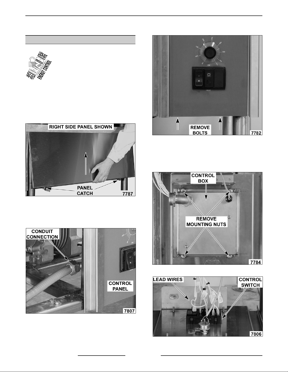
Front, Rear & Side Panels
1. Lift up on the bottom edge of panel until it clears
the catch.
2. Tilt outwards and allow the panel to drop down.
3. Reverse procedure to install.
5. Tilt bottom of control panel outwards and pull
down.
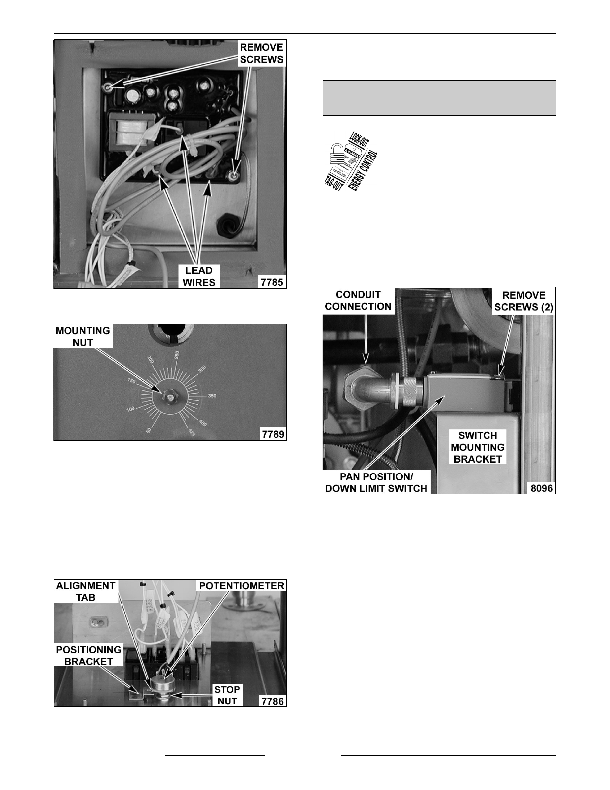
Control Panel
1. Remove front panel.
2. Disconnect conduit from control box.
NOTE: The control panel should be supported to
remove lead wire strain.
6. Remove control box from control panel.
7. Disconnect lead wires from control switch.
3. Remove manual lift crank handle (if installed).
4. Remove bolts securing control panel to braising
pan frame. Bolts are recessed in the frame
channel.
F25121 (February 2003) Page 4 of 32
Page 5
GAS BRAISING PANS - REMOVAL AND REPLACEMENT OF PARTS
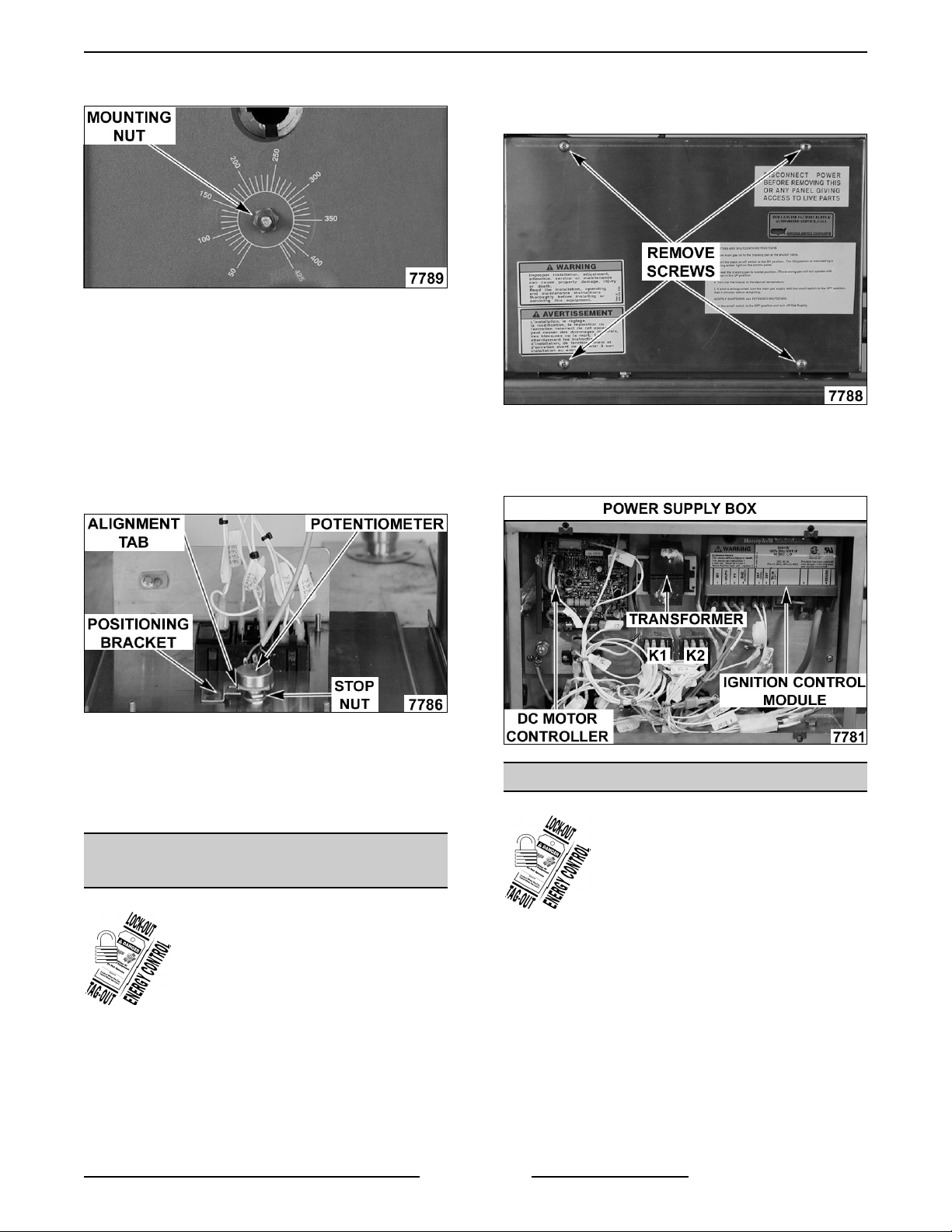
8. Pull temperature dial from potentiometer shaft
and remove mounting nut.
9. Control panel is removed.
10. To install.
A. Align tab on potentiometer with positioning
bracket on panel.
B. Install mounting nut and tighten.
C. Adjust stop nut on potentiometer body (as
necessary) to ensure a water tight seal on
mounting nut.
D. Attach temperature dial.
1. Remove front panel as outlined under
COVERS AND PANELS.
2. Remove power supply box cover.
3. Remove the component being replaced.
4. Reverse procedure to install the replacement
component then check for proper operation.
11. Reverse procedure from step 6 to complete the
installation.
12. Check calibration as outlined under
TEMPERATURE CONTROLLER
CALIBRATION.
POWER SUPPLY BOX
COMPONENTS
WARNING: DISCONNECT THE
ELECTRICAL POWER TO THE
MACHINE AND FOLLOW LOCKOUT /
TAGOUT PROCEDURES.
CAUTION: Certain components in this system
are subject to damage by electrostatic discharge
during field repairs. A field service grounding kit
is available to prevent damage. The field service
grounding kit must be used anytime a control
board is handled.
Page 5 of 32
TEMPERATURE CONTROLLER
WARNING: DISCONNECT THE
ELECTRICAL POWER TO THE
MACHINE AND FOLLOW LOCKOUT /
TAGOUT PROCEDURES.
1. Remove control box from the control panel as
outlined under COVERS AND PANELS.
2. Disconnect lead wires from temperature
controller.
3. Remove temperature controller from control
box.
F25121 (February 2003)
Page 6
GAS BRAISING PANS - REMOVAL AND REPLACEMENT OF PARTS
4. Pull temperature dial from potentiometer shaft
and remove mounting nut.
7. Check calibration as outlined under
TEMPERATURE CONTROLLER
CALIBRATION.
PAN POSITION/DOWN LIMIT
SWITCH
WARNING: DISCONNECT THE
ELECTRICAL POWER TO THE
MACHINE AND FOLLOW LOCKOUT /
TAGOUT PROCEDURES.
1. Remove front and left side panels as outlined
under COVERS AND PANELS.
2. Disconnect conduit and remove pan
position/down limit switch from switch mounting
bracket.
LEFT SIDE VIEW SHOWN
5. To install:
A. Align tab on potentiometer with positioning
bracket on panel.
B. Install mounting nut and tighten.
C. Adjust stop nut on potentiometer body (as
necessary) to ensure a water tight seal on
mounting nut.
D. Attach temperature dial.
6. Reverse procedure from step 3 to complete the
installation.
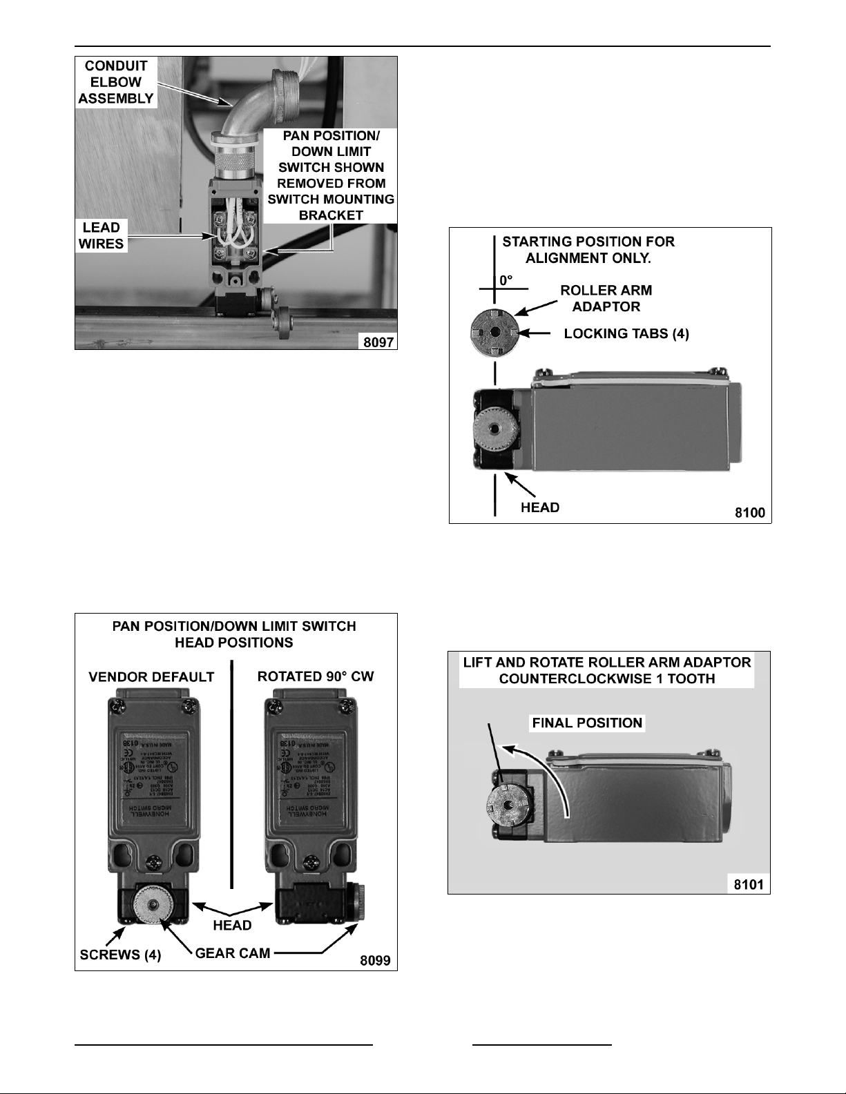
3. Remove cover from switch.
4. Disconnect lead wires and pull wires thru
conduit elbow assembly.
5. Remove conduit elbow assembly from switch.
F25121 (February 2003) Page 6 of 32
Page 7
GAS BRAISING PANS - REMOVAL AND REPLACEMENT OF PARTS
NOTE: When installing, replace the o-ring seal
(provided) inside the brass fitting and re-use conduit
elbow assembly.
6. To install:
C. Place switch on its side with the head to
the left and gear cam pointing up.
D. Align roller arm adaptor with the four
locking tabs pointing up and position one
of the tabs at 0°.
NOTE: The 0° position of the roller arm locking tab
is the starting point for alignment only. The locking
tab cannot remain at the 0° position.
SIDE VIEW SHOWN
A. Position the switch with the head pointing
toward installer and gear cam pointing up.
NOTE: The plunger on the head is spring loaded
and will push the head away from switch body when
the last screw is removed.
B. Remove screws securing the head to
switch body, rotate 90° clockwise and
tighten screws to secure.
TOP VIEW SHOWN
E. Place roller arm adaptor on the gear cam
to engage the teeth. Lift the adaptor until
the teeth just slightly disengage from the
gear cam. Rotate the roller arm adaptor
counterclockwise 1 tooth, re-engage teeth
and release the adaptor.
Page 7 of 32
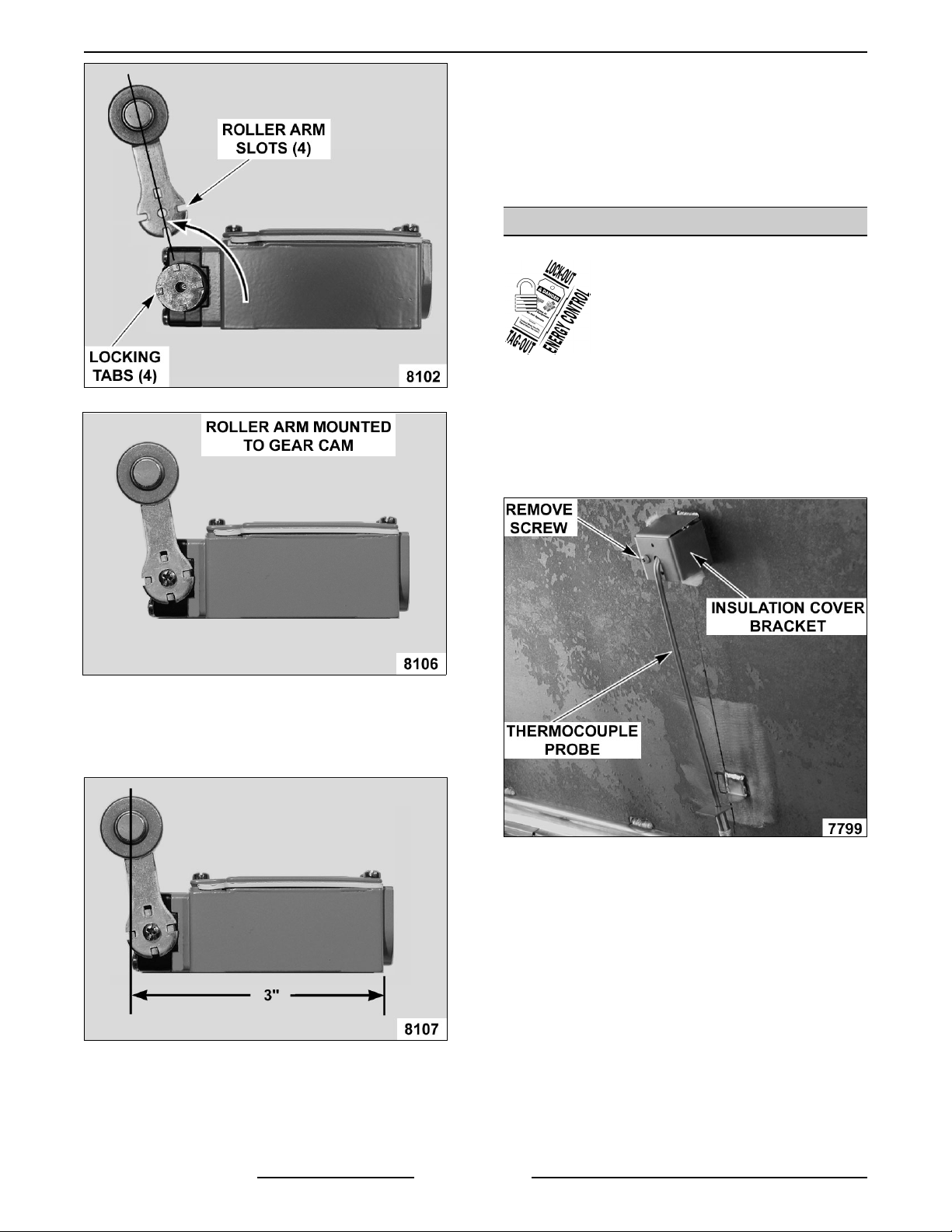
F. Align the roller arm slots with the four
locking tabs on the roller arm adaptor and
tighten mounting screw to secure.
F25121 (February 2003)
Page 8
GAS BRAISING PANS - REMOVAL AND REPLACEMENT OF PARTS
7. Reverse procedure from step 5 to complete the
installation.
8. Adjust pan position/down limit switch on switch
mounting bracket as outlined under PAN
POSITION SWITCH ADJUSTMENT in
SERVICE PROCEDURES AND
ADJUSTMENTS.
THERMOCOUPLE PROBE
WARNING: DISCONNECT THE
ELECTRICAL POWER TO THE
MACHINE AND FOLLOW LOCKOUT /
TAGOUT PROCEDURES.
1. Access temperature controller as outlined under
TEMPERATURE CONTROLLER .
2. Disconnect thermocouple lead wires.
3. Raise the pan to the full tilt position.
4. Remove insulation cover bracket.
G. Verify roller arm position on switch.
1) Measure the distance from the rear of
the switch body to the center of the
roller. The distance should be 3".
H. If distance is ok, proceed to step 7.
I. If distance is not ok, adjust the roller arm
position (as necessary) to obtain the 3"
roller arm dimension.
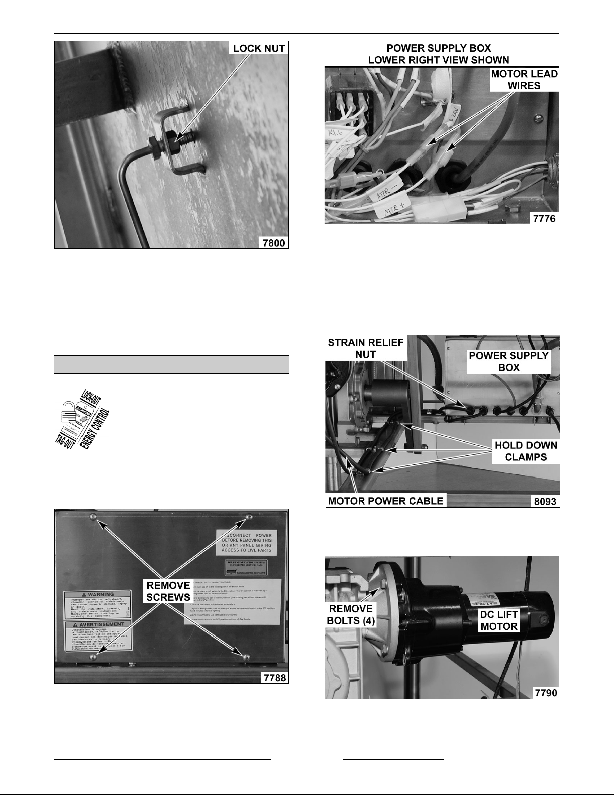
5. Loosen lock nut and remove threaded probe
from pan.
F25121 (February 2003) Page 8 of 32
Page 9
GAS BRAISING PANS - REMOVAL AND REPLACEMENT OF PARTS
6. Reverse procedure to install and check for
proper operation.
NOTE: When installing: Route thermocouple wire in
the same manner thru the metal clamps on the hinge
& frame. Tighten thermocouple just until it touches
the pan; do not over tighten or damage to the
thermocouple may occur.
NOTE: Lead wires can be identified by label or
marking on the wire.
4. Loosen the strain relief nut and the hold down
clamps for the motors' power cable. Pull the
cable thru the strain relief opening and remove
the cable form underneath the clamps.
VG30 REAR VIEW SHOWN
DC LIFT MOTOR
WARNING: DISCONNECT THE
ELECTRICAL POWER TO THE
MACHINE AND FOLLOW LOCKOUT /
TAGOUT PROCEDURES.
1. Remove front, rear and right side panels as
outlined under COVERS AND PANELS.
2. Remove power supply box cover.
5. Remove motor mounting bolts from gear
reducer flange.
6. Remove motor from gear reducer.
3. Disconnect DC lift motor lead wires labeled
MTR+ (positive) & MTR - (negative).
Page 9 of 32
F25121 (February 2003)
Page 10
GAS BRAISING PANS - REMOVAL AND REPLACEMENT OF PARTS
7. To install:
A. With drive key on shaft, install motor to
gear reducer.
B. Route and secure the motors' power cable
and re-connect motor lead wires.
C. Replace power supply box cover and side
panels.
8. Check for proper operation.
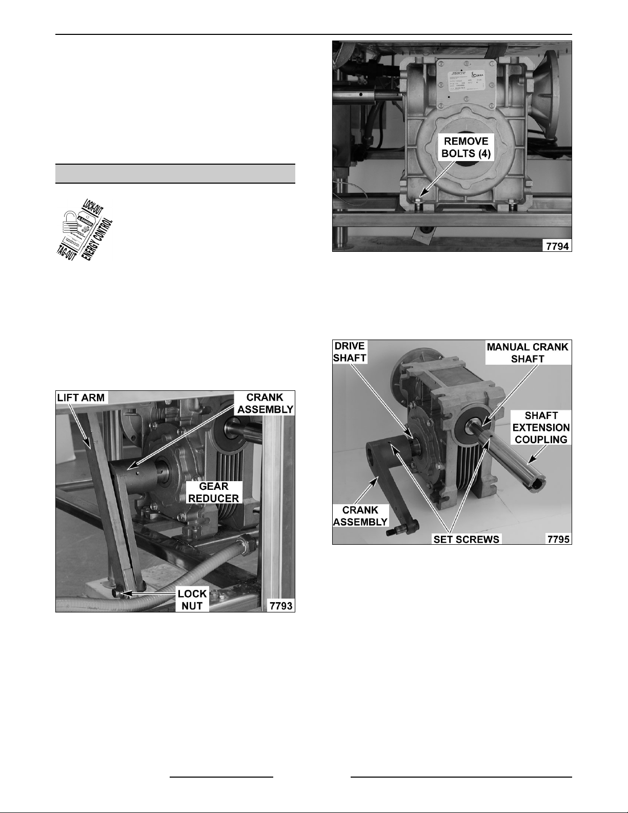
GEAR REDUCER
WARNING: DISCONNECT THE
ELECTRICAL POWER TO THE
MACHINE AND FOLLOW LOCKOUT /
TAGOUT PROCEDURES.
1. Remove right side and rear panels as outlined
under COVERS AND PANELS.
2. Lower the pan (use motorized pan lift or manual
crank).
3. If DC lift motor is installed, remove motor as
outlined under DC LIFT MOTOR.
4. Remove lock nut securing crank assembly to lift
arm.
6. Loosen set screw on crank assembly and
remove the assembly from drive shaft.
7. Loosen set screw on shaft extension coupling
and remove the coupling from manual crank
shaft.
8. To install:
5. Remove bolts securing gear reducer to braising
pan frame then remove gear reducer.
F25121 (February 2003) Page 10 of 32
A. With drive key on drive shaft, install crank
assembly and tighten set screw against
key.
B. With drive key on manual crank shaft,
install shaft extension coupling and tighten
set screw against key.
C. Place gear reducer in its mounting location
on frame. Position gear reducer so the
shaft extension coupling is aligned with the
opening in control panel; and the lift arm is
vertical and parallel to the crank assembly
when connected.
Page 11

GAS BRAISING PANS - REMOVAL AND REPLACEMENT OF PARTS
NOTE: On the bottom lift arm bushing, the bushing
head must
crank assembly to create approximately 1/32"
spacing.
9. Reverse procedure from step 5 to complete the
10. Check for proper operation.
be positioned between the lift arm and the
installation.
GAS COMBINATION VALVE
5. Disconnect lead wires from gas combination
valve.
6. Disconnect pilot tube from gas combination
valve.
WARNING: DISCONNECT THE
ELECTRICAL POWER TO THE
MACHINE AND FOLLOW LOCKOUT /
TAGOUT PROCEDURES.
WARNING: SHUT OFF THE GAS SUPPLY
BEFORE SERVICING THE UNIT.
WARNING: ALL GAS JOINTS DISTURBED
DURING SERVICING MUST BE CHECKED FOR
LEAKS. CHECK WITH A SOAP AND WATER
SOLUTION (BUBBLES). DO NOT USE AN OPEN
FLAME.
1. Remove front, rear and left side panels as
outlined under COVERS AND PANELS.
2. Remove screw from the top cover of gas
combination valve box.
3. Remove silicone sealant around the gas pipe
and the slot in top cover then remove the
cover.
NOTE: When installing, clean the areas and apply
silicone sealant.
4. Remove U-bolt securing gas valve box to gas
pipe then remove box.
7. Separate gas pipe union (near manifold),
remove U-bolt securing gas pipe to braising
pan frame (at rear of pan) then remove the gas
combination valve and piping assembly.
8. Remove pipe from gas combination valve.
9. Reverse procedure to install.
NOTE: When installing, clean gas pipe threads and
apply pipe joint compound to threads. Any pipe joint
compound used must
propane gases.
be resistant to the action of
Page 11 of 32
F25121 (February 2003)
Page 12

GAS BRAISING PANS - REMOVAL AND REPLACEMENT OF PARTS
10. Check for proper operation.
PILOT BURNER
WARNING: DISCONNECT THE
ELECTRICAL POWER TO THE
MACHINE AND FOLLOW LOCKOUT /
TAGOUT PROCEDURES.
WARNING: SHUT OFF THE GAS SUPPLY
BEFORE SERVICING THE UNIT.
WARNING: ALL GAS JOINTS DISTURBED
DURING SERVICING MUST BE CHECKED FOR
LEAKS. CHECK WITH A SOAP AND WATER
SOLUTION (BUBBLES). DO NOT USE AN OPEN
FLAME.
1. Raise the pan to the full tilt position.
2. Remove pilot burner mounting bracket from the
burner box pan.
3. Disconnect ignitor cable from ignitor/flame
sense electrode on the pilot burner.
4. Remove pilot burner from pilot mounting
bracket.
5. Disconnect pilot tube from pilot burner.
7. Reverse procedure to install and check for
proper operation.
RUNNER TUBE
WARNING: DISCONNECT THE
ELECTRICAL POWER TO THE
MACHINE AND FOLLOW LOCKOUT /
TAGOUT PROCEDURES.
6. To remove gas orifice from pilot burner for
inspection or cleaning, disconnect the pilot tube
compression fitting from pilot burner body.
A. The gas orifice is inserted into pilot burner
body and should drop out when
compression fitting is removed. If
necessary, lightly tap on pilot burner body
to free the gas orifice.
CAUTION: If orifice is clogged with debris, clean
with air or non-flammable liquid only.
WARNING: SHUT OFF THE GAS SUPPLY
BEFORE SERVICING THE UNIT.
WARNING: ALL GAS JOINTS DISTURBED
DURING SERVICING MUST BE CHECKED FOR
LEAKS. CHECK WITH A SOAP AND WATER
SOLUTION (BUBBLES). DO NOT USE AN OPEN
FLAME.
1. Raise the pan to the full tilt position.
2. Loosen screw on each runner tube clamp and
rotate the clamp away from runner tube.
3. Lift runner tube from mounting bracket and off
F25121 (February 2003) Page 12 of 32
of the gas orifice.
Page 13

GAS BRAISING PANS - REMOVAL AND REPLACEMENT OF PARTS
NOTE: Runner tube slides onto the gas orifice.
When installing, ensure runner tube is fully seated
onto gas orifice.
4. To remove gas orifice for inspection or
cleaning, disconnect the gas supply tube
compression fitting at the manifold.
5. Remove gas orifice from elbow fitting.
CAUTION: If orifice is clogged with debris, clean
with air or non-flammable liquid only.
6. Reverse procedure to install and check for
proper operation.
MAIN BURNERS
WARNING: DISCONNECT THE
ELECTRICAL POWER TO THE
MACHINE AND FOLLOW LOCKOUT /
TAGOUT PROCEDURES.
3. Lift burner at rear to clear the locating pin hole
and slide burner toward the rear of burner box
pan to clear the orifice.
4. To remove gas orifice for inspection or
cleaning, remove the gas orifice from the elbow
fitting.
CAUTION: If orifice is clogged with debris, clean
with air or non-flammable liquid only.
5. Reverse procedure to install and adjust air
shutter as outlined under MAIN BURNERS.
NOTE: When installing, ensure locating pin is in the
hole for proper
attached.
positioning and hold down wire is re-
LID SPRINGS
WARNING: DISCONNECT THE
ELECTRICAL POWER TO THE
MACHINE AND FOLLOW LOCKOUT /
TAGOUT PROCEDURES.
1. Lower the lid to the full down position.
NOTE: For spring tension to be set correctly, both
the left and right side springs must be replaced.
2. Remove spring covers by prying up at the
bottom. The covers are held in place by tabs on
the bottom of cover.
RIGHT SIDE REAR VIEW SHOWN
WARNING: SHUT OFF THE GAS SUPPLY
BEFORE SERVICING THE UNIT.
WARNING: ALL GAS JOINTS DISTURBED
DURING SERVICING MUST BE CHECKED FOR
LEAKS. CHECK WITH A SOAP AND WATER
SOLUTION (BUBBLES). DO NOT USE AN OPEN
FLAME.
1. Raise the pan to the full tilt position.
2. Remove the hold down wire from main burner.
Page 13 of 32
3. Place a 1 5/8" wrench on the lid spring lock nut
and apply a downward force until locking pin
can be removed. Continue to hold lock nut in
place.
Caution: Do not release wrench while locking pin
is removed or damage to the braising pan may
occur.
F25121 (February 2003)
Page 14

GAS BRAISING PANS - REMOVAL AND REPLACEMENT OF PARTS
A. Slowly release downwards force to remove
spring tension.
B. Rotate lid spring lock nut to the next hole
position then replace locking pin. Continue
until all spring tension is removed, one
position at a time.
C. Remove bolts securing the inside lid
bearing housing to the lid support bracket.
4. To install:
A. Slide the spring onto the lid spring
mandrel. Insert spring into locator hole on
the lid spring retainer.
B. Slide the lid spring lock nut onto the lid
spring mandrel. Insert spring into locator
hole on the lid spring lock nut.
C. Replace
lid bearing housing.
5. Replace spring on the opposite side.
6. Adjust spring tension as outlined under LID
SPRING TENSION ADJUSTMENT IN
SERVICE PROCEDURES AND
ADJUSTMENTS.
D. Remove lid bearing housing
, lid spring lock
nut and the spring, from spring mandrel.
F25121 (February 2003) Page 14 of 32
Page 15

GAS BRAISING PANS - SERVICE PROCEDURES AND ADJUSTMENTS
SERVICE PROCEDURES AND ADJUSTMENTS
WARNING: CERTAIN PROCEDURES IN THIS SECTION REQUIRE ELECTRICAL TEST OR MEASUREMENTS
WHILE POWER IS APPLIED TO THE MACHINE. EXERCISE EXTREME CAUTION AT ALL TIMES. IF TEST
POINTS ARE NOT EASILY ACCESSIBLE, DISCONNECT POW ER AND FOLLOW LOCKOUT / TAGOUT
PROCEDURES, ATTACH TEST EQUIPMENT AND REAPPLY POWER TO TEST.
TEMPERATURE CONTROLLER
CALIBRATION
than
than
NOTE: Verify condition of thermocouple as outlined
under THERMOCOUPLE TEST before proceeding.
1. At the geometric center on the pan cooking
surface, clean an area approximately 3" inches
in diameter.
2. Apply a thin layer of fresh cooking oil to the
cleaned area and place a temperature sensing
disk on the pan cooking surface.
3. Turn on/off switch on and set temperature dial
to 250°F.
4. Monitor the heat light (red) on the control panel.
When temperature controller is calling for heat,
light will be on. If temperature controller is
satisfied, light will be off.
A. Allow the temperature controller to cycle
three times to stabilize the pan
temperature.
B. Record the temperature when the
temperature controller cycles off and on for
the next three cycles.
5. Calculate the differential by subtracting the
temperature indicated when heat light goes out
from temperature indicated when heat light
comes on.
A. If the average temperature is less
10°F of the dial setting, temperature
controller is properly calibrated.
B. If the average temperature is more
10°F of the dial setting, temperature
controller calibration must
7. Using the temperature scale on the overlay as a
guide, align the edge on a short piece of tape to
the temperature calculated in step 6 and apply
tape to knob as a reference point.
8. Remove temperature dial from shaft.
9. Loosen screws on the back of dial.
A. Hold the knob and rotate dial to the edge of
the tape used for reference. This
adjustment offsets the indicated
temperature on the dial to the actual
temperature measured.
NOTE: With knob facing user, a clockwise
rotation increases temperature and a counterclockwise rotation decrease temperature.
B. Hold the dial & knob together to maintain
the adjusted setting and tighten screws.
be adjusted.
A. The differential calculated should be less
than 20°F.
1) If the differential is less
temperature controller is functioning
properly.
a. Proceed to average temperature.
2) If the differential is more
the temperature controller is
malfunctioning.
a. Install a replacement
temperature controller and check
calibration.
6. Calculate the average temperature by adding
the temperature indicated when the heat lamp
goes out to the temperature indicated when the
heat lamp comes on & divide this answer by 2.
than 20°F,
than 20°F,
10. Replace temperature dial on shaft.
11. Turn the temperature dial to the lowest setting
Page 15 of 32
then back to 250°F.
F25121 (February 2003)
Page 16

GAS BRAISING PANS - SERVICE PROCEDURES AND ADJUSTMENTS
12. Repeat the average temperature calculation for
up to three attempts. Allow the pan to cycle at
least two times between adjustments before
performing the calculation.
13. If calibration is unsuccessful, the controller may
be malfunctioning and cannot be adjusted
properly. Install a replacement temperature
controller and check calibration.
TEMPERATURE CONTROLLER
TEST
NOTE: The controller is powered whenever supply
power is connected to the machine.
7. Disconnect lead wire labeled "HT.0" from the
COM terminal on the controller.
8. Verify 24VAC between the disconnected "HT.0"
lead wire and ground.
A. If correct, re-connect lead wire to COM
terminal and proceed to step 9.
B. If incorrect, check transformer and the
on/off switch for proper operation.
9. Disconnect lead wire labeled "HT.1" from the
N.O. terminal on the controller.
10. Verify 24VAC between N.O. terminal on the
temperature controller and ground.
A. If correct, internal relay "HEAT" contacts
are functioning properly. Reconnect lead
wire to the N.O. terminal.
B. If incorrect, install a replacement
temperature controller and check for
proper operation.
THERMOCOUPLE TEST
1. Access the temperature controller as outlined
in REMOVAL AND REPLACEMENT OF
PARTS.
1. Lower the pan to the full down position.
2. Access the temperature controller as outlined in
REMOVAL AND REPLACEMENT OF PARTS.
3. Re-connect power to the machine.
4. Verify temperature controller is receiving
120VAC at terminals L1 & L2, polarity is correct
and machine is properly grounded.
5. Turn on/off switch on and set temperature dial
to 250/F.
6. Verify heat light (red) comes on and main
burners light.
A. If heat light and main burners come on but
turn off within 10 seconds, verify condition
of thermocouple as outlined under
THERMOCOUPLE TEST.
NOTE: Temperature controller will de-energize
internal relay if the circuitry detects an open
thermocouple.
B. If heat light and main burners do not
on, verify internal relay "HEAT" contacts
are operating properly.
come
2. Remove thermocouple lead wires from
temperature controller.
3. Check the thermocouple for resistance.
A. If meter reads an overload (OL) condition
(open), or zero ohms (short) replace the
thermocouple and check temperature
controller for proper operation.
4. If resistance is measured, thermocouple is
good.
F25121 (February 2003) Page 16 of 32
Page 17

GAS BRAISING PANS - SERVICE PROCEDURES AND ADJUSTMENTS
SPARK IGNITION TEST
If the ignition control module is not generating a
spark or the spark is not sufficient to light pilot
burner, perform the following test.
1. Lower the pan to the full down position, turn the
on/off switch on and set the temperature dial to
call for heat.
B. Inspect the ignitor electrode and ground
clip for contaminates, or corrosion. Clean
those surfaces as necessary.
C. The spark gap between the ignitor/flame
sense electrode and the ground clip should
be 0.120" ± 0.020". If the gap is outside of
this dimension, bend the ground clip as
necessary, to make the adjustment.
2. Verify the ignition control module is receiving
24VAC between terminals 5 & 6.
A. If voltage is present, turn the on/off switch
off and proceed to step 3.
B. If voltage is not present, see schematic
diagram.
3. Disconnect power to the machine.
WARNING: SHUT OFF THE GAS SUPPLY
BEFORE SERVICING THE UNIT.
WARNING: ALL GAS JOINTS DISTURBED
DURING SERVICING MUST BE CHECKED FOR
LEAKS. CHECK WITH A SOAP AND WATER
SOLUTION (BUBBLES). DO NOT USE AN OPEN
FLAME.
4. Verify all electrical connections (including
ground) on the ignition control module are
secure.
5. Access the pilot burner as outlined in
REMOVAL AND REPLACEMENT OF PARTS.
6. Verify the ground connection on pilot burner
mounting bracket is clean and secure. The pilot
burner should have good metal to metal contact
to the pilot mounting bracket.
D. Check the ignitor cable connection for
tightness and damaged insulation. If the
ignitor cable appears to be damaged, then
install a replacement ignitor cable.
8. Install pilot burner and connect ignitor cable.
9. Disconnect main valve (MV) lead wire from
terminal 1 on the ignition control module.
7. Remove pilot burner and check the following:
A. Inspect the ceramic insulator on the
ignitor/flame sense electrode for cracks or
evidence of exposure to extreme heat,
which can permit leakage to ground. If
either of these conditions exist, then install
a replacement pilot burner.
NOTE: Removal of lead wire prevents main burners
from lighting with the pan raised and the pan
position/down limit switch manually operated.
10. Reconnect power to the machine and turn the
Page 17 of 32
gas supply on.
F25121 (February 2003)
Page 18

GAS BRAISING PANS - SERVICE PROCEDURES AND ADJUSTMENTS
11. Turn on/off switch on and set the temperature
dial to call for heat.
12. Manually operate pan position/down limit switch
and observe spark from ignitor.
A. If spark from ignitor is present and lights
the gas for pilot burner, and pilot burner
remains lit, then the system is working
properly.
B. If pilot burner lights but does not maintain
an adequate flame during the trial for
ignition (90 seconds):
D. If ignitor is still not sparking, turn the on/off
switch off, disconnect power to the
machine and turn the gas supply off.
13. Install a replacement ignition control module
and check for proper operation.
PILOT BURNER FLAME
ADJUSTMENT
1. Turn the on/off switch off.
2. Raise the pan to the full tilt position.
3. Remove left side panel as outlined under
COVERS AND PANELS.
4. Access the ignition control module as outlined
under POWER SUPPLY BOX COMPONENTS
IN REMOVAL AND REPLACEMENT OF
PARTS.
5. Disconnect main valve (MV) lead wire from
terminal 1 on the ignition control module.
NOTE: Removal of lead wire prevents main burners
from lighting with the pan raised and the pan
position/down limit switch manually operated.
6. Reconnect power to the machine.
7. Turn on/off switch on and set the temperature
dial to call for heat.
8. Manually operate pan position/down limit switch
and observe pilot burner flame.
1) Check pilot burner orifice for clogging.
CAUTION: If orifice is clogged with debris, clean
with air or non-flammable liquid only.
2) Check pilot burner flame adjustment
as outlined under SERVICE
PROCEDURES AND
ADJUSTMENTS.
C. If spark from ignitor is present but does not
light the pilot gas before ignition control
module locks out, there may not be
enough gas in the supply line for ignition.
Release the pan position/down limit switch
to remove power and re-set the module.
Wait 5 minutes between ignition tries for
unburned gas to vent.
Manually operate pan position/down limit
switch and sparking should resume. The
module may need to be re-set several
times before ignition takes place.
1) If pilot burner ignition is successful,
release the pan position/down limit
switch, turn the on/off switch to off
and re-connect main valve (MV) lead
wire on the ignition control module.
A. If flame envelops 3/8" to 1/2" of the
ignitor/flame sense electrode, pilot burner
is adjusted properly.
B. If flame is outside of the specified range,
release the pan position/down limit switch
and
continue with procedure.
9. Remove adjustment screw cap to access the
pilot burner flame adjustment screw.
F25121 (February 2003) Page 18 of 32
Page 19

GAS BRAISING PANS - SERVICE PROCEDURES AND ADJUSTMENTS
4. Set VOM to micro amp scale (DC) and connect
the black meter lead (-) to the asterisk (*)
terminal and red meter lead (+) to terminal 8.
10. Manually operate pan position/down limit switch
and observe pilot burner flame.
A. To increase pilot flame, turn the screw
counterclockwise. To decrease pilot flame,
turn the screw clockwise
11. Once the pilot flame
correctly, release the pan position
switch, turn the on/off switch off and replace the
adjustment screw cap.
12. Re-connect main valve (MV) lead wire from
terminal 1 on the ignition control module.
13. Lower the pan to the full down position and
check for proper operation.
has been adjusted
.
/down limit
FLAME SENSE CURRENT TEST
NOTE: You must complete the SPARK IGNITION
TEST prior to checking flame sense current.
If pilot burner lights but will not maintain flame,
perform the following test.
1. Turn the on/off switch off.
2. Access the ignition control module as outlined
under POWER SUPPLY BOX COMPONENTS
IN REMOVAL AND REPLACEMENT OF
PARTS.
5. Turn on/off switch on and set the temperature
dial to call for heat.
6. With pilot burner lit, meter reading should be
above 1.0 micro amp (minimum) and steady.
A. If reading is greater than or equal to 1.0
micro amp then flame sense current is
within tolerance.
1) Turn on/off switch off and replace
jumper wire.
B. If reading is less than 1.0 micro amp and
the condition of the ignitor/flame sense has
been verified as good, turn on/off switch
off.
7. Install a replacement ignition control module
and check for proper operation.
IGNITION CONTROL MODULE
TEST
3. Remove jumper wire between terminals marked
with an asterisk (*) & 8.
Page 19 of 32
1. Lower the pan to the full down position, turn the
on/off switch on and set the temperature dial to
call for heat.
F25121 (February 2003)
Page 20

GAS BRAISING PANS - SERVICE PROCEDURES AND ADJUSTMENTS
2. Ignition control module is energized and trial
for ignition starts (90 seconds).
A. Verify 24VAC between terminals 5 & 6.
1) If voltage is not present, see
schematic diagram.
3. Pilot valve (PV) contacts close to energize the
pilot valve coil, allowing gas flow to the pilot
burner.
A. Verify 24VAC between terminals 2 & 3.
1) If voltage is not present, replace
ignition control module and check for
proper operation.
4. At the same time, spark voltage is sent from
terminal 9 to the ignitor/flame sense electrode
and sparking begins.
The pilot burner lights, pilot flame is sensed,
spark voltage from terminal 9 is removed and
sparking stops. Main valve (MV) contacts close
to energize main valve coil, allowing gas flow
to the runner tube and main burners.
A. Verify 24VAC between terminals 1 and 2.
1) If voltage is not present, replace
ignition control module and check for
proper operation.
5. With pilot burner lit, the runner tube lights and
main burners light.
GAS MANIFOLD PRESSURE
ADJUSTMENT
WARNING: SHUT OFF THE GAS SUPPLY
BEFORE SERVICING THE UNIT.
GAS PRESSURE (INCHES W.C.)
Gas
Type
Natural 3.7 7.0 5.0
Propane 10.0 11.0 11.0
NOTE: If the incoming line pressure is less
the minimum stated, then the manifold pressure
cannot be set correctly.
1. Lower the pan to the full down position.
2. Remove front panel as outlined under COVERS
3. Access the gas combination valve as outlined in
4. Remove 1/8" NPT pipe plug on the outlet side
5. Install a hose barb adaptor at the port and
Manifold
Recommended Min Max
AND PANELS in REMOVAL AND
REPLACEMENT OF PARTS.
REMOVAL AND REPLACEMENT OF PARTS.
of the gas valve (manifold pressure tap).
attach a manometer.
Line
14.0
than
6. As long as the temperature controller is calling
for heat and the ignition control module is
sensing a sufficient flame sense current, the
pilot valve (PV) and main valve (MV) contacts
will remain closed.
NOTE: If pilot burner does not immediately light, the
ignition control module continues sparking for 90
seconds, then locks out power to the gas
combination valve (pilot valve and main valve
remain closed). The module remains locked out
until the on/off switch is cycled to reset the system
re-start the ignition trial cycle.
6. Turn gas supply, gas combination valve and
on/off switch to on.
A. Set the temperature dial to call for heat.
B. Verify main burners light.
7. Observe manometer pressure reading and
compare to the gas pressure table.
A. If other appliances are connected to the
same gas line, turn them all on and check
manometer pressure reading again. If a
pressure drop of 1/2" W.C. or more is
observed, then the gas supply needs to be
checked by the gas line installer or the
local gas company for adequate sizing.
B. If adjustment is necessary, continue with
procedure.
8. Remove adjustment screw cap to access the
pressure adjustment screw.
A. To increase pressure, turn the screw
clockwise
screw counterclockwise
. To decrease pressure, turn the
.
F25121 (February 2003) Page 20 of 32
Page 21

GAS BRAISING PANS - SERVICE PROCEDURES AND ADJUSTMENTS
NOTE: Accurate gas pressure adjustments can only
be made with the gas on and the main burners lit.
9. Set pressure as listed in gas pressure table.
10. Once the correct pressure has been set, turn
the on/off switch off, replace the adjustment
screw cap and pipe plug.
11. Check for proper operation.
MAIN BURNERS
CAUTION: To prevent discoloration of the
cooking surface, and possible pan warpage at
temperature settings above 250°F, do not
operate the braising pan unless the cooking
surface is covered with water or a thin layer of
cooking oil.
5. Allow burners to remain lit for at least five
minutes.
6. Observe each burners< flame thru the opening
in the front of the burner box.
A. If the flame is blue, air shutter is adjusted
properly. A slight tinge of orange in the
flame is acceptable.
B. If the flame is yellow tipping, this indicates
too little primary air (oxygen) for proper
combustion. The heating efficiency is
reduced, and the amount of soot (carbon)
generated as a by-product is increased.
Continue with procedure to adjust.
7. Loosen screw on the air shutter for the burner
being adjusted. Closing the air shutter will
decrease
the shutter will increase
primary air to the burner and opening
primary air the burner.
FRONT VIEW OF BURNER AIR SHUTTER
SHOWN
Inspection
1. Access the main burners as outlined in
REMOVAL AND REPLACEMENT OF PARTS.
2. Inspect burners for clogged ports or
obstructions around air shutter. Clean the
burner (as necessary) using a soft bristle
brush.
3. Inspect gas orifice for clogging. If clogs are
found, remove the orifice and clean with air or
non-flammable liquid only.
NOTE: If the orifice was removed, be sure to install
the orifice in the same location. The outside burners
use a slightly larger orifice than the center burner(s).
Air Shutter Adjustment
1. Verify the gas manifold pressure as outlined
under GAS MANIFOLD PRESSURE
ADJUSTMENT.
2. Turn the on/off switch off.
3. Remove the control panel as outlined in
REMOVAL AND REPLACEMENT OF PARTS
to gain viewing access to the right side burner.
8. Monitor the burner flame and set the air shutter
opening as follows:
A. Adjust the air shutter (as necessary) to
obtain a blue flame. A slight tinge of
orange in the flame is acceptable.
B. After the air shutter adjustment is made,
tighten the set screw.
9. Adjust the remaining burners as necessary.
4. Turn the on/off switch on and set the
temperature dial to call for heat.
Page 21 of 32
F25121 (February 2003)
Page 22

GAS BRAISING PANS - SERVICE PROCEDURES AND ADJUSTMENTS
DC MOTOR CONTROLLER TEST
A. If voltage is present but pan does not raise,
refer to MOTORIZED LIFT OPTION ONLY
under TROUBLESHOOTING.
B. If voltage is not present and the fuse is ok,
turn the on/off switch off and disconnect
power to the machine.
11. Instal a replacement DC motor controller and
check for proper operation.
PAN POSITION/DOWN LIMIT
SWITCH ADJUSTMENT
NOTE: Do not use the motorized lift (if installed) for
this procedure.
1. Turn the on/off switch off.
2. Remove front and left side panels as outlined
under COVERS AND PANELS.
3. Insert the manual crank handle.
4. Raise the pan to the full tilt position.
5. Verify roller arm position on switch.
A. Measure the distance from the rear of the
switch body to the center of the roller. The
distance should be 3".
1. Lower the pan to the full down position.
2. Raise the lid to the full open position.
3. Access the DC motor controller as outlined
under POWER SUPPLY BOX COMPONENTS
in REMOVAL AND REPLACEMENT OF
PARTS.
4. Set VOM to measure AC volts and connect
meter leads at L1 & L2 on the controller.
5. Turn the on/off switch to on.
6. Verify 120VAC at L1 & L2 on the controller
when the lift control switch (momentary) is
operated to raise & lower the pan.
A. If voltage is present but pan does not raise
& lower, proceed to step 7.
B. If voltage is not present refer to
MOTORIZED LIFT OPTION ONLY under
TROUBLESHOOTING.
7. Disconnect power to the machine.
8. Set VOM to measure DC volts and connect
VOM leads to terminals A + (positive) & A (negative) on the controller.
SIDE VIEW SHOWN
B. If distance is ok, proceed to step 6.
C. If distance is not ok, position the roller arm
as outlined under PAN POSITION/DOWN
LIMIT SWITCH in REMOVAL AND
REPLACEMENT OF PARTS.
6. Lower the pan to the full down position. The
roller should make contact with the hinge and
operate the switch.
9. Re-connect power to the machine.
10. Verify 90VDC (approximate) from the DC motor
controller when the lift control switch
(momentary) is operated to raise & lower the
pan.
F25121 (February 2003) Page 22 of 32
7. Verify pan position/down limit switch N.O.
contacts are closing.
A. Turn the on/off switch on and set the
temperature dial to call for heat.
B. Heat light (red) comes on and main
burners light.
Page 23

GAS BRAISING PANS - SERVICE PROCEDURES AND ADJUSTMENTS
1) If main burners do not light, verify
24VAC input to the switch, and that
the voltage is output from the switch.
2) If voltage is present on the output
side of the switch, the switch is
functioning properly.
3) If voltage is not present, install a
replacement pan position/down limit
switch and repeat this procedure to
adjust.
8. Verify pan position/down limit switch N.O.
contacts are opening.
A. Slowly raise the pan until the heat light
and burners go out then stop.
B. At the rear of the pan, measure the
distance from the bottom of the pan skirt
to the flat surface covering the frame.
1) Distance should be 2.25" to 2.50".
LEFT SIDE VIEW SHOWN
LEFT SIDE VIEW SHOWN
B. Adjust mounting switch bracket up or
down (as necessary) to obtain the rear
pan dimension of 2.25" to 2.50".
11. Repeat steps 5 thru 9 to check for proper
operation.
LID SPRING TENSION
ADJUSTMENT
NOTE: For reference, this is approximately 5
angular degrees.
9. If heat light and main burners go out and the
measured distance is within the acceptable
range, switch is adjusted properly. If both
conditions are not satisfied, adjustment is
necessary.
10. To Adjust:
A. Loosen screws on the mounting switch
bracket.
1. Raise the lid and release at several positions
thru the range of travel.
A. If lid remains in place, no adjustment is
necessary.
B. If lid does not remain in place (springs up
or falls down), continue with procedure.
NOTE: For spring tension to be set correctly, each
spring must be adjusted the same amount.
2. Remove spring covers by prying up at the
bottom. The covers are held in place by tabs on
the bottom of cover.
RIGHT SIDE REAR VIEW SHOWN
Page 23 of 32
F25121 (February 2003)
Page 24

GAS BRAISING PANS - SERVICE PROCEDURES AND ADJUSTMENTS
3. To adjust:
A. Place a 1 5/8" wrench on the lid spring lock
nut and apply a downward force until
locking pin can be removed. Continue to
hold lock nut in place.
CAUTION: Do not release wrench while locking
pin is removed or damage to the braising pan
may occur.
B. Apply additional downward force to
increase
downwards force to decrease
tension.
C. Rotate lid spring lock nut to the next hole
position then replace locking pin. Adjust
the spring tension, one position at a time.
D. Repeat tension adjustment on the opposite
spring.
4. Repeat step 1 to verify adjustment. Make
additional adjustments as necessary.
spring tension; or slowly release
spring
F25121 (February 2003) Page 24 of 32
Page 25

GAS BRAISING PANS - ELECTRICAL OPERATION
ELECTRICAL OPERATION
COMPONENT FUNCTION
BRAISING PAN CONTROLS
Temperature Controller .... Monitors thermocouple input (type E) and regulates braising pan temperature. An
external set point potentiometer is used for temperature adjustments.
Transformer ............. Supplies 24VAC for heating circuit. If motorized pan lift option is installed,
supplies 24VAC for lift control circuit.
ON/OFF Switch .......... Controls 24VAC to the gas heating circuit. If motorized pan lift option is installed,
controls power to lift circuit.
Power On Light (Amber) . . . Indicates on/off switch is turned on.
Heat Light (Red) .......... Indicates temperature controller is calling for heat and pan is down.
Pan Position/
Down Limit Switch ........ N.O. contacts function as pan position switch to power the gas heating circuit
when pan is down. Removes power from gas heating circuit when pan is raised.
The N.C. contacts are used for the down limit switch (motorized lift option only).
Ignition Control Module . . . Controls and monitors gas heating. Energizes pilot valve coil to supply gas to
pilot, generates spark to light gas at the pilot, monitors the presence of flame and
energizes the main valve coil upon a call for heat.
Ignitor/Flame Sense
Electrode ................ Ignites pilot burner and senses the presence of a flame. The Igniter/Flame Sense
is a component of the pilot burner.
Gas Combination
Valve ................... Allows gas flow to the pilot burner when pilot valve coil is energized; and gas flow
to the runner tube & main burners when main valve coil is energized. Also,
regulates gas manifold pressure.
MOTORIZED PAN LIFT OPTION CONTROLS
DC Motor Controller ....... Controls DC lift motor operation for raising & lowering of the pan, and provides
motor acceleration control each time the controller is powered. The controller
outputs approximately 90VDC to power the motor.
DC Lift Motor ............. Operates gear reducer to raise or lower the pan. When the correct voltage
polarity is applied thru K1 contacts, motor rotates CW to raise pan. W hen reverse
voltage polarity is applied thru K2 contacts, motor rotates CCW to lower the pan.
Lid Switch ............... Supplies 24VAC power to lift control switch. Used to ensure lid is open before pan
can be raised.
Lift Control Switch
(Momentary On/Off/On) .... Energizes K1 relay coil thru up limit switch contacts (N.C.) to raise the pan.
Energizes K2 relay coil thru down limit switch contacts (N.C.) to lower the pan.
The switch positions are: Center neutral (starting) position off; Momentary on lower pan; Momentary on - raise pan.
Up Limit Switch .......... Removes power from K1 relay coil when pan reaches full tilt (pan travel stops).
Pan Position/
Down Limit Switch ........ N.C. contacts function as down limit switch to remove power from K2 relay coil
when pan is lowered to the down position (pan travel stops). The N.O. contacts
are used for the pan position switch.
K1 "Up" Relay (3PDT) ..... Supplies power to motorized lift circuit to raise the pan when 24VAC coil is
energized.
K2 "Down" Relay (3PDT) . . . Supplies power to motorized lift circuit to lower the pan when 24VAC coil is
energized by the lift control switch. The voltage polarity to the DC motor is
reversed thru K2 contacts to turn motor CCW and lower the pan.
Page 25 of 32
F25121 (February 2003)
Page 26

GAS BRAISING PANS - ELECTRICAL OPERATION
COMPONENT LOCATION
F25121 (February 2003) Page 26 of 32
Page 27

GAS BRAISING PANS - ELECTRICAL OPERATION
IGNITION CONTROL MODULE
The ignition control module is energized when 24 volts is applied between terminals 5 & 6.
The module outputs 24 volts from terminals 2 & 3 to the pilot valve coil (PV) on the gas combination valve,
allowing gas flow to the pilot burner.
At the same time, the module generates a spark voltage output of approximately 13K at terminal 9 to begin
sparking at the ignitor/flame sense electrode.
The sparking will continue until an adequate pilot flame sense current is sensed by the module or for a maximum
of 90 seconds.
NOTE: If pilot is not established within the 90 second ignition trial time, the ignition module locks out by removing
power to the gas combination valve. The system remains locked out until the on/off switch is cycled to reset the
system and re-start the ignition trial cycle.
With the pilot burner lit, a flame sense current in DC micro amps is rectified thru the ignitor cable back to
terminal 9.
When the module senses a sufficient pilot flame current, the module outputs 24 volts from terminal 1 & 2 to
energize the main valve coil (MV) on the gas combination valve, allowing gas flow to the runner tube and main
burners.
When power to the ignition control module is removed, the output voltages are also removed. The pilot valve coil
(PV) and the main valve coil (MV) on the gas combination valve are de-energized and close. Gas flow to the pilot
burner, runner tube and main burners stop and all burners go out.
Page 27 of 32
F25121 (February 2003)
Page 28

GAS BRAISING PANS - ELECTRICAL OPERATION
SEQUENCE OF OPERATION
Refer to schematic diagram AI1341 for the electrical
sequence of operation. Manual pan lift is the
standard configuration.
Heating
1. Conditions.
A. 120VAC to braising pan, polarity is correct,
and is properly grounded.
1) Temperature controller energized.
2) 24VAC transformer energized.
B. Temperature dial at lowest setting
(potentiometer fully CCW).
NOTE: Temperature controller internal relay
"HEAT" contacts remain open (N.O.).
C. Pan temperature is below 200/F.
D. On/off switch off.
E. Pan position/down limit switch N.O.
contacts closed (pan down).
F. Gas supply on.
G. Gas combination control valve on.
2. Turn on/off switch on.
A. Indicator light (amber) comes on.
3. Set the temperature dial to call for heat.
A. Internal relay on temperature controller is
energized and the "HEAT" contacts close
(N.O.).
1) Heat light (red) comes on.
2) Ignition control module.
NOTE: If pan is raised 2.25" to 2.50" at the rear,
pan position/down limit switch N.O. contacts will
open and de-energize the heating circuit.
4. Refer to IGNITION CONTROL MODULE.
5. Braising pan reaches set point temperature.
A. Internal relay on temperature controller is
de-energized and the "HEAT" contacts
open (N.O.).
1) Heat light (red) goes out.
2) Power is removed from the ignition
control module.
6. Braising pan will continue to cycle with the
temperature controller until the pan is raised or
the on/off switch is turned off.
Motorized Pan Lift (Option)
Refer to the dashed line sections labeled
"MOTORIZED LIFT OPTION" on the schematic
diagram for the integration of the motorized pan lift
components into the sequence of operation.
1. Conditions.
A. 120VAC to braising pan, polarity is correct,
and is properly grounded.
B. 24VAC transformer energized.
C. On/off switch off.
D. Lift control switch off (center position).
E. Lid switch N.O. contacts closed (lid
opened).
F. Up limit switch N.C. contacts closed (pan
position is less than full tilt).
G. Pan position/down limit switch N.O.
contacts closed; and
N.C. contacts open
(pan down).
NOTE: The pan position/down limit
contained in the same switch body. Both sets of
DPST contacts are utilized.
2. Turn on/off switch on.
A. Indicator light (amber) comes on.
NOTE: If the temperature dial is set to call for
heat, the ignition trial starts and module begins
sparking.
3. Operate the lift control switch to raise the pan
(momentary on - raise).
A. K1 relay coil is energized thru the up limit
switch N.C contacts.
1) K1 4/7 N.O. contacts close.
2) K1 9/6 N.O. contacts close.
3) K1 8/5 N.O. contacts close.
B. 120VAC to DC motor controller thru K1 4/7
N.O. contacts.
1) 90VDC output is activated at terminals
A + (positive) and A - (negative). DC
lift motor powered thru K1 9/6 N.O.
contacts, K1 8/5 N.O. contacts and
pan raises.
4. When the pan is raised 2.25" to 2.50" at the
rear, pan position/down limit switch contacts
change state. The N.O contacts open to remove
power from the heating circuit; and the N.C
contacts close. Power is then available for K2
relay coil thru the N.C. set of contacts.
switch are
F25121 (February 2003) Page 28 of 32
The pan can still be raised or lowered thru its
travel range by operating the lift control switch.
Release switch to stop pan travel.
Page 29

GAS BRAISING PANS - ELECTRICAL OPERATION
5. Pan reaches full tilt position, the up limit switch
N.C. contacts open and K1 relay coil is deenergized.
A. The three sets of K1 contacts return to
N.O. position. Power is removed from the
DC motor controller, the DC lift motor and
pan travel stops.
6. Operate the lift control switch to lower the pan
(momentary on - lower).
A. K2 relay coil is energized thru the down
limit switch N.C contacts.
1) K2 4/7 N.O. contacts close.
2) K2 9/6 N.O. contacts close.
3) K2 8/5 N.O. contacts close.
B. 120VAC to DC motor controller thru K2 4/7
N.O. contacts.
1) 90VDC output is activated at terminals
A + (positive) and A - (negative). DC
lift motor powered thru K2 9/6 N.O.
contacts, K2 8/5 N.O. contacts and
pan lowers.
7. After the pan leaves the full tilt position, the up
limit switch N.C. contacts close. The direction of
pan travel can then be reversed by un-operating
the switch (pan travel stops) then operating the
switch to raise the pan.
8. Pan reaches full down position, down limit
switch N.C. contacts open and K2 relay coil is
de-energized.
A. The three sets of K2 contacts return to
N.O. position. Power is removed from the
DC motor controller, the DC lift motor and
pan travel stops.
Page 29 of 32
F25121 (February 2003)
Page 30

GAS BRAISING PANS - ELECTRICAL OPERATION
SCHEMATIC DIAGRAM
F25121 (February 2003) Page 30 of 32
Page 31

GAS BRAISING PANS - TROUBLESHOOTING
TROUBLESHOOTING
GAS HEATING (MANUAL LIFT OR MOTORIZED LIFT OPTION)
SYMPTOMS POSSIBLE CAUSES
No spark to ignite pilot burner gas, power on
light is lit.
Spark at ignitor but pilot burner does not light. 1. Gas combination valve off or inoperative.
Pilot burner lights but will not maintain flame. 1. Ignitor/flame sense lead wire connections malfunction.
Main burner(s) do not light or will not
maintain flame.
Braising pan does not heat, power on light is
lit.
Braising pan does not heat, power on light is
not lit.
Excessive or low heat. 1. Temperature probe malfunction.
1. Pan not fully lowered or pan position/down limit switch
malfunction.
2. Temperature dial not set to call for heat or temperature
controller malfunction.
3. Ignitor cable open or grounded (short).
4. Ignitor spark gap distance incorrect.
5. Shorted electrode or an improper ground on
ignitor/flame sense.
6. Ignition module not grounded or inoperative.
2. Gas supply off or insufficient gas pressure.
3. Ignitor spark gap distance incorrect.
4. Pilot burner orifice obstructed.
5. Ignition Module malfunction.
2. Improper ground on pilot burner or ignitor/flame sense;
or ignitor/flame sense malfunction.
3. Pilot burner misaligned or Ignitor/flame sense
malfunction.
4. Gas pressure not within specified range.
5. Incorrect polarity from transformer to Ignition module.
6. Ignition Module malfunction.
1. Gas pressure incorrect.
2. Runner tube - gas orifice obstructed or malfunction.
3. Main burner - gas orifice obstructed or malfunction.
4. Main Burner(s) incorrect air shutter position or burner
malfunction.
5. Gas combination valve malfunction.
1. Temperature controller malfunction.
2. Pan position/down limit switch malfunction.
3. Ignition module malfunction.
4. Gas combination valve malfunction.
5. Interconnecting wiring malfunction.
1. Main circuit breaker off or power not connected.
2. On/off switch off or malfunction.
3. Transformer inoperative.
4. Interconnecting wiring malfunction.
2. Temperature controller malfunction.
3. Gas pressure incorrect.
4. Gas orifice obstructed or incorrect.
Page 31 of 32
F25121 (February 2003)
Page 32

GAS BRAISING PANS - CONDENSED SPARE PARTS LIST
MOTORIZED LIFT OPTION ONLY
SYMPTOM POSSIBLE CAUSES
Pan will not raise. 1. Lid switch open (lid not opened) or malfunction.
2. Transformer inoperative.
3. On/off switch off or malfunction.
4. Lift control switch malfunction (momentary on - raise).
5. Up limit switch malfunction.
6. K1 relay malfunction.
7. DC motor controller - Fuses open or controller malfunction.
8. DC Lift motor inoperative.
9. Gear reducer malfunction.
Pan will not lower. 1. Lid switch open (lid not opened) or malfunction.
2. Pan position is below 2.25" to 2.50" at the rear. Raise pan to
return pan position/down limit switch N.C. contacts to closed
position.
3. Transformer inoperative.
4. On/off switch off or malfunction.
5. Lift control switch malfunction (momentary on - lower).
6. Down limit switch malfunction.
7. K2 relay malfunction.
8. DC motor controller - Fuses open or controller malfunction.
9. DC Lift motor inoperative.
10. Gear reducer malfunction.
CONDENSED SPARE PARTS LIST
VG30 & VG40 GAS BRAISING PANS
PART NUMBER DESCRIPTION NOTE
854534-1 Board, Temperature
854537-1 Switch, Control (Manual Lift)
417980-1 Module, ignitor
411500-12 Transformer, 120-24
854517-1 Switch, Limit (Pan Position/Down limit)
854512-1 Thermocouple (E-Type)
844129-1 Pilot, Burner (Nat) Elect. Ign.
844129-2 Pilot, Burner (LP) Elect. Ign.
844130-1 Cable, Ignitor
844133-1 Valve, Combo Gas (Nat), Elect. Ign.
844133-2 Valve, Combo Gas (LP), Elect. Ign.
BRAISING PANS WITH MOTORIZED LIFT OPTION
PART NUMBER DESCRIPTION NOTE
854495-1 Switch, Control
854671-1 Controller, Speed
854545-1 Relay (24VAC)
411496-F1 Switch, Micro (Lid)
854717-1 Switch, Micro (Up Limit)
854653-1 Motor, Gear
F25121 (February 2003) Printed in U.S.A.
 Loading...