

Page 1
INSTALLATION &
OPERATION MANUAL
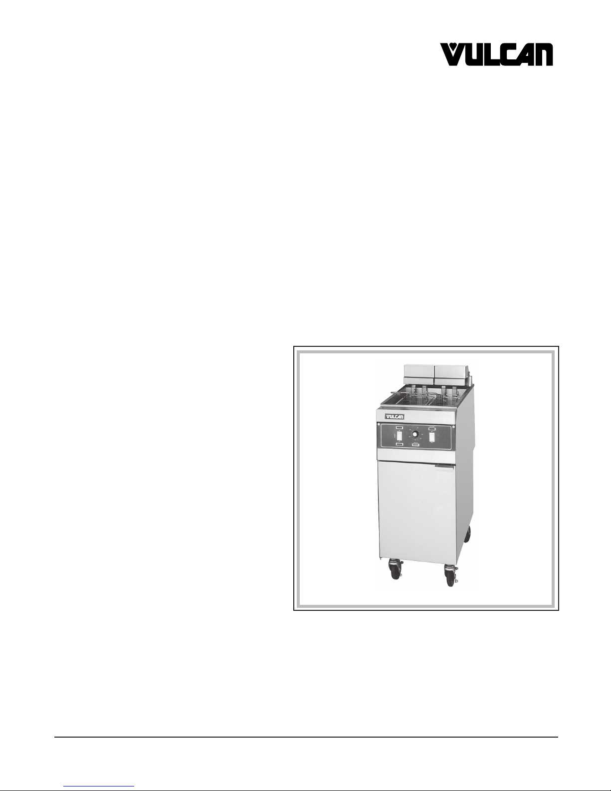
ERD/ERC SERIES ELECTRIC FRYERS
MODEL
ERD40 ML-114614
ERD50 ML-114615
ERD225 ML-114616
ERD85 ML-114617
ERC40 ML-114618
ERC50 ML-114619
ERC225 ML-114620
ERC85 ML-114621
ERO15 ML-114622
ERO21 ML-114623
ERD40
VULCAN-HART COMPANY, P.O. BOX 696, LOUISVILLE, KY 40201-0696, TEL. (502) 778-2791
FORM 30981 Rev. C (Apr. 2003)
Page 2

TABLE OF CONTENTS
GENERAL . . . . . . . . . . . . . . . . . . . . . . . . . . . . . . . . . . . . . . . . . . . . . . . . . . . . . . . . . . . . . . . . . . . . . . . . . . 3
INSTALLATION . . . . . . . . . . . . . . . . . . . . . . . . . . . . . . . . . . . . . . . . . . . . . . . . . . . . . . . . . . . . . . . . . . . . . . 6
Unpacking . . . . . . . . . . . . . . . . . . . . . . . . . . . . . . . . . . . . . . . . . . . . . . . . . . . . . . . . . . . . . . . . . . . . 6
Location . . . . . . . . . . . . . . . . . . . . . . . . . . . . . . . . . . . . . . . . . . . . . . . . . . . . . . . . . . . . . . . . . . . . . . 6
Installation Codes and Standards . . . . . . . . . . . . . . . . . . . . . . . . . . . . . . . . . . . . . . . . . . . . . . . . . 6
Assembly . . . . . . . . . . . . . . . . . . . . . . . . . . . . . . . . . . . . . . . . . . . . . . . . . . . . . . . . . . . . . . . . . . . . . 6
Leveling . . . . . . . . . . . . . . . . . . . . . . . . . . . . . . . . . . . . . . . . . . . . . . . . . . . . . . . . . . . . . . . . . . . . . . 7
Electrical Connections . . . . . . . . . . . . . . . . . . . . . . . . . . . . . . . . . . . . . . . . . . . . . . . . . . . . . . . . . . 7
OPERATION . . . . . . . . . . . . . . . . . . . . . . . . . . . . . . . . . . . . . . . . . . . . . . . . . . . . . . . . . . . . . . . . . . . . . . . . 8
Before First Use . . . . . . . . . . . . . . . . . . . . . . . . . . . . . . . . . . . . . . . . . . . . . . . . . . . . . . . . . . . . . . . 8
Filling the Fry Tank with Shortening . . . . . . . . . . . . . . . . . . . . . . . . . . . . . . . . . . . . . . . . . . . . . . . 8
Adding Solid Shortening . . . . . . . . . . . . . . . . . . . . . . . . . . . . . . . . . . . . . . . . . . . . . . . . . . . . . . . . . 9
Daily Shortening Addition (All Models) . . . . . . . . . . . . . . . . . . . . . . . . . . . . . . . . . . . . . . . . . . . . . 9
Controls — ERD Series . . . . . . . . . . . . . . . . . . . . . . . . . . . . . . . . . . . . . . . . . . . . . . . . . . . . . . . . 10
Melting Solid Shortening (Model ERD) . . . . . . . . . . . . . . . . . . . . . . . . . . . . . . . . . . . . . . . . . . . . 11
Turning the ERD Fryer On . . . . . . . . . . . . . . . . . . . . . . . . . . . . . . . . . . . . . . . . . . . . . . . . . . . . . . 11
Turning the ERD Fryer Off . . . . . . . . . . . . . . . . . . . . . . . . . . . . . . . . . . . . . . . . . . . . . . . . . . . . . . 11
High Limit Control . . . . . . . . . . . . . . . . . . . . . . . . . . . . . . . . . . . . . . . . . . . . . . . . . . . . . . . . . . . . . 11
Frying (All Models) . . . . . . . . . . . . . . . . . . . . . . . . . . . . . . . . . . . . . . . . . . . . . . . . . . . . . . . . . . . . 12
Daily Filtering . . . . . . . . . . . . . . . . . . . . . . . . . . . . . . . . . . . . . . . . . . . . . . . . . . . . . . . . . . . . . . . . . 12
Shortening Life (All Models) . . . . . . . . . . . . . . . . . . . . . . . . . . . . . . . . . . . . . . . . . . . . . . . . . . . . . 14
Controls — ERC Series . . . . . . . . . . . . . . . . . . . . . . . . . . . . . . . . . . . . . . . . . . . . . . . . . . . . . . . . 15
Power-Up . . . . . . . . . . . . . . . . . . . . . . . . . . . . . . . . . . . . . . . . . . . . . . . . . . . . . . . . . . . . . . . . . . . . 16
To Begin Melt Cycle . . . . . . . . . . . . . . . . . . . . . . . . . . . . . . . . . . . . . . . . . . . . . . . . . . . . . . . . . . . 16
Cooking . . . . . . . . . . . . . . . . . . . . . . . . . . . . . . . . . . . . . . . . . . . . . . . . . . . . . . . . . . . . . . . . . . . . . 17
Manual Cooking Operation . . . . . . . . . . . . . . . . . . . . . . . . . . . . . . . . . . . . . . . . . . . . . . . . . . . . . . 17
Cooking Time Remaining . . . . . . . . . . . . . . . . . . . . . . . . . . . . . . . . . . . . . . . . . . . . . . . . . . . . . . . 17
Completion . . . . . . . . . . . . . . . . . . . . . . . . . . . . . . . . . . . . . . . . . . . . . . . . . . . . . . . . . . . . . . . . . . . 17
Successive Product Cooking . . . . . . . . . . . . . . . . . . . . . . . . . . . . . . . . . . . . . . . . . . . . . . . . . . . . 17
During Slack Periods . . . . . . . . . . . . . . . . . . . . . . . . . . . . . . . . . . . . . . . . . . . . . . . . . . . . . . . . . . 18
Idle Mode . . . . . . . . . . . . . . . . . . . . . . . . . . . . . . . . . . . . . . . . . . . . . . . . . . . . . . . . . . . . . . . . . . . . 18
Operator Advice . . . . . . . . . . . . . . . . . . . . . . . . . . . . . . . . . . . . . . . . . . . . . . . . . . . . . . . . . . . . . . 18
Using the Editor . . . . . . . . . . . . . . . . . . . . . . . . . . . . . . . . . . . . . . . . . . . . . . . . . . . . . . . . . . . . . . . 18
Programming the Controller . . . . . . . . . . . . . . . . . . . . . . . . . . . . . . . . . . . . . . . . . . . . . . . . . . . . . 18
Definitions — Edit Product . . . . . . . . . . . . . . . . . . . . . . . . . . . . . . . . . . . . . . . . . . . . . . . . . . . . . . 19
Overview of Programming . . . . . . . . . . . . . . . . . . . . . . . . . . . . . . . . . . . . . . . . . . . . . . . . . . . . . . 19
Edit Product . . . . . . . . . . . . . . . . . . . . . . . . . . . . . . . . . . . . . . . . . . . . . . . . . . . . . . . . . . . . . . . . . . 20
Sel Setback . . . . . . . . . . . . . . . . . . . . . . . . . . . . . . . . . . . . . . . . . . . . . . . . . . . . . . . . . . . . . . . . . . 20
Calibrate. . . . . . . . . . . . . . . . . . . . . . . . . . . . . . . . . . . . . . . . . . . . . . . . . . . . . . . . . . . . . . . . . . . . . 20
Boil Out . . . . . . . . . . . . . . . . . . . . . . . . . . . . . . . . . . . . . . . . . . . . . . . . . . . . . . . . . . . . . . . . . . . . . 21
Recovery . . . . . . . . . . . . . . . . . . . . . . . . . . . . . . . . . . . . . . . . . . . . . . . . . . . . . . . . . . . . . . . . . . . . 21
Select Melt . . . . . . . . . . . . . . . . . . . . . . . . . . . . . . . . . . . . . . . . . . . . . . . . . . . . . . . . . . . . . . . . . . . 21
Manual Setup. . . . . . . . . . . . . . . . . . . . . . . . . . . . . . . . . . . . . . . . . . . . . . . . . . . . . . . . . . . . . . . . . 21
Oil Shutdown . . . . . . . . . . . . . . . . . . . . . . . . . . . . . . . . . . . . . . . . . . . . . . . . . . . . . . . . . . . . . . . . . 21
Oil Tmr/Cntr . . . . . . . . . . . . . . . . . . . . . . . . . . . . . . . . . . . . . . . . . . . . . . . . . . . . . . . . . . . . . . . . . . 22
Error Messages . . . . . . . . . . . . . . . . . . . . . . . . . . . . . . . . . . . . . . . . . . . . . . . . . . . . . . . . . . . . . . . 23
Cleaning . . . . . . . . . . . . . . . . . . . . . . . . . . . . . . . . . . . . . . . . . . . . . . . . . . . . . . . . . . . . . . . . . . . . . 23
MAINTENANCE . . . . . . . . . . . . . . . . . . . . . . . . . . . . . . . . . . . . . . . . . . . . . . . . . . . . . . . . . . . . . . . . . . . . . 24
Lubrication . . . . . . . . . . . . . . . . . . . . . . . . . . . . . . . . . . . . . . . . . . . . . . . . . . . . . . . . . . . . . . . . . . . 24
Service and Parts Information . . . . . . . . . . . . . . . . . . . . . . . . . . . . . . . . . . . . . . . . . . . . . . . . . . . 24
— 2 —
Page 3

Installation, Operation and Care of
MODEL ERD/ERC SERIES ELECTRIC FRYERS
SAVE THESE INSTRUCTIONS FOR FUTURE USE
GENERAL
Vulcan ERD/ERC Series Electric Fryers are available in 3 sizes with an array of features and options
for a range of commercial fryer applications. While the overall tank width on the ER40 and ER50 are
the same, the ER50 has a deeper tank area than the ER40.
Width Fry Compound
Model KW Inches / cm Lb / kg
ERD/ERC40 14 & 17 151/2 / 39 35-40 / 16-18
ERD/ERC50 14, 17 & 21 151/2 / 39 45-50 / 20-23
ERD/ERC225 14, 17 & 21 151/2 / 39 50 / 23
ERD/ERC85 24 21 / 53 85-100 / 39-45
Voltage ranges are: 208/240, 3 Phase
220/380, 3 Phase, 4 Wire
240/415, 3 Phase, 4 Wire
480, 3 Phase.
Model ER Series Fryers can be freestanding or arranged in batteries of 2 to 5 fryers. The number
preceding the model number of your fryer refers to the number of fryers in a battery. One fryer in a
battery can be a Frymate Dump Station (ERO15 for ER40 and ER50, ERO21 for ER85) (only one per
battery).
ERD Fryers have a solid state thermostat and ERC Fryers have a microprocessor (computer)
thermostat and timer control.
Feature options include Basket Lift(s) with Timer(s); Tri, Twin, or Single Baskets; Filter Ready and
Battery Interplumbing. Finish options include S/S Sides and Casters. S/S Legs are standard.
Your Vulcan fryer is constructed and designed to give long satisfactory service, providing it is properly
installed, adjusted and maintained.
The Mobile Filter is covered under a separate Installation and Operation Manual.
— 3 —
Page 4
ER Series Fryer — Features
Model
ERD 225 Std. N/A N/A
ERD40, ERD50 Std. Solid State Opt. Std. Opt. N/A
ERD85 Std. Opt. Opt.
ERC40, ERC50
ERC85 Std. Opt. Opt.
Model Filter Ready
ERD40/ERC40 Opt. (Use MF50) Opt. Opt.
ERD50/ERC50 Opt. (Use MF50) Opt. Opt.
ERD225 Opt. (Use MF50) Opt. Opt.
ERD85/ERC85 Opt. (Use MF85) Opt. Opt.
Fat Melt
Cycle Twin Single Tri
Std. Computer Opt.
ER Series Fryer — Construction Features
Thermostat Basket Lift(s)
Battery Battery
Configuration Interplumbing
Basket(s)
Std. Opt. N/A
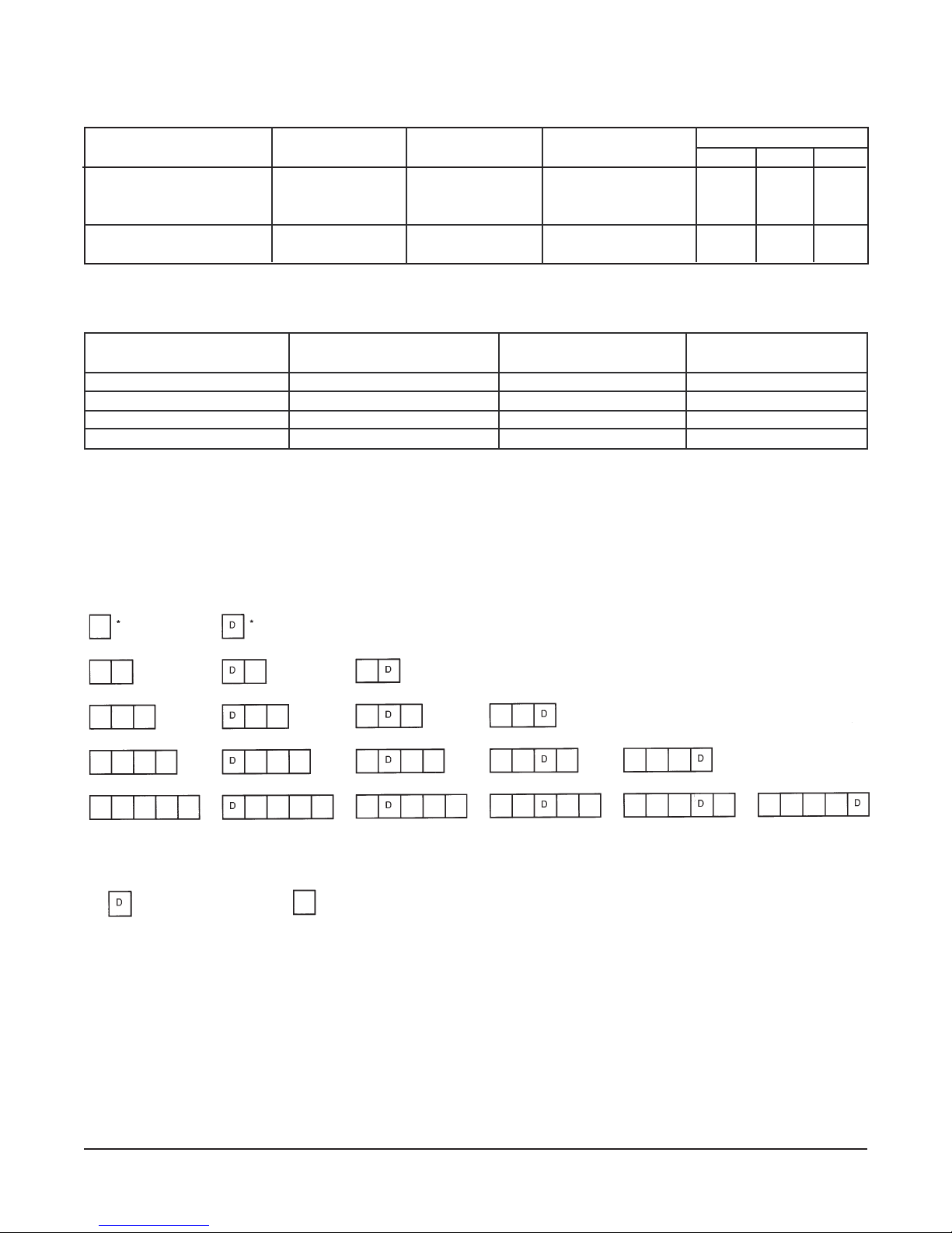
BATTERY CONFIGURATIONS
Batteries of up to five fryers wide can be configured with any ER Series Fryer or ERO Frymate Dump
1
Station (either 15
/2" [39 cm] or 21" [53 cm ] wide). Possible configurations showing positions A through
E are depicted below:
NOTES:
= Dump Station; = Fryer.
*Indicates filter interplumbing not available.
A filter dump station can be located under any position in a battery if it has been built without an ERO Frymate.
A filter dump station can be located under any position in a battery if the line-up has been built with an ERO
Frymate located at either end of the battery.
When an ERO Frymate is built between two fryers within a battery, the filter dump station is located under the
ERO Frymate.
In two-unit batteries utilizing an ERO Frymate, the filter dump station will always be located under the fryer.
All options and accessories can be used with batteried equipment.
ERO15 is used on Models ER40 or ER50.
ERO21 is used on Model ER85.
— 4 —
Page 5

Field Installable Accessories Factory Installed Only
Casters Fat Melt
Twin Baskets Basket Lift
Single Baskets S/S Tank
Tri Baskets (ER85 only) S/S Sides
Heat Lamp Battery Configuration
S/S Vat Cover Battery Interplumbing
Batter Tray
Tank Skimmer
Tank Scoop
ERO SERIES FRYMATE (Dump Station)
1
Model ERO Frymate Dump Station can be configured in batteries with fryers in either 15
/2" (39 cm)or
21" (53 cm) width. Frymate provides a final prep area where excess oil drains away and product is
seasoned, packaged, and kept ready for sale.
ERO Series Frymate — Finish Options
Model ERO15, ERO21 Front Door Sides Legs
Standard Stainless Steel Painted Steel Stainless Steel Legs
Optional Not Applicable Stainless Steel Casters
*Model ERO15 is for use with all ER40, ER50 and ER225 Series Fryers.
Model ERO21 is for use with the ER85 Series Fryers.
ERO Series Frymate — Features
Heat Lamp
Opt. Std. Opt. Opt. Opt. Opt.
Drain Solid Pan Solid Pan Perforated
*Side liners are not available in batteries with ERO interplumbed Frymates.
Tops
Side Liners*
— 5 —
Page 6

INSTALLATION
Before installing the fryer, verify that the electrical service agrees with the specifications on the fryer
data plate which is located on the inside of the door panel. If the supply and equipment requirements
do not agree, do not proceed with the installation. Contact your dealer or Vulcan-Hart Company
immediately.
UNPACKING
Immediately after unpacking the fryer, check for possible shipping damage. If the fryer is found to be
damaged, save the packaging material and contact the carrier within 15 days of delivery.
Do not use the door or its handle to lift or move the fryer.
LOCATION
The fryer may be installed at 0" clearance from the back or side walls. A 16" (40.6 cm) clearance is
required to any open top flame burner. Position the fryer for easy accessibility for service.
INSTALLATION CODES AND STANDARDS
Your Vulcan fryer must be installed in accordance with:
1. State and local codes.
2. The National Electrical Code, ANSI/NFPA No. 70 (latest edition). Copies may be obtained from The
National Fire Protection Association, Batterymarch Park, Quincy, MA 02269.
3. NFPA Standard #96.
ASSEMBLY
The fryer must be restrained with adequate ties to prevent tipping when installed in order to avoid the
splashing of hot liquid.
Legs
Position fryer in an open space near the final installation area. Tilt fryer on its side, being careful to
avoid scratching the finish. Thread legs into mounting holes provided on bottom of fryer by screwing
in a clockwise rotation until tight.
Carefully raise fryer to its normal position and place it in the installing location.
Casters (Optional)
It is recommended that casters be installed on all batteried appliances. A strain relief (Fig. 1) is supplied
to protect the electrical supply line.
If it is necessary to disconnect the restraint, unplug electrical supply before disconnection. Reconnect
the restraint before plugging the electrical supply in and returning the fryer to its installation position.
Instructions for installing casters to the fryer are included with the casters.
— 6 —
Page 7
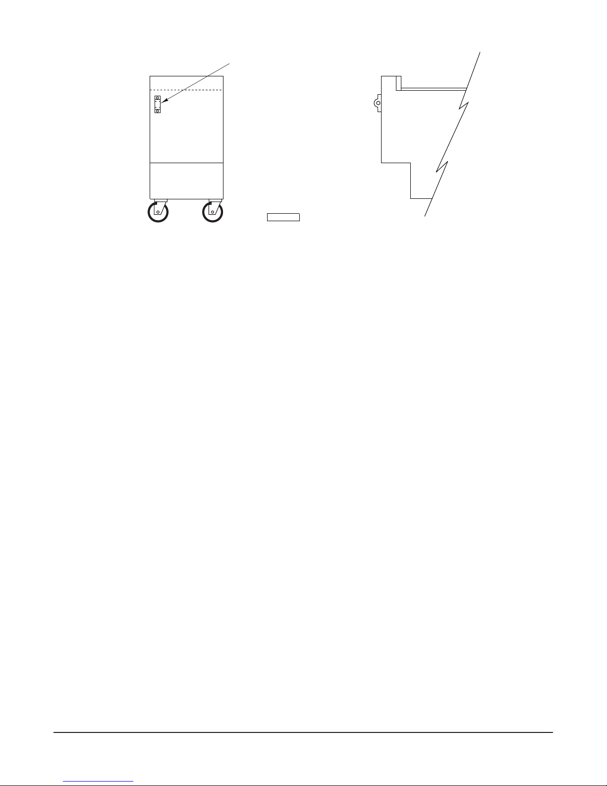
STRAIN RELIEF
FITTING
THIS SIDE ONLY.
(Strain relief fitting
supplied by Vulcan-Hart.
Chain to be supplied by
others.)
PL-53583
Fig. 1
LEVELING
Place a carpenter's level on top of the fryer and level the fryer front-to-back and side-to-side by turning
the adjustable legs.
ELECTRICAL CONNECTIONS
WARNING: ELECTRICAL AND GROUNDING CONNECTIONS MUST COMPLY WITH THE NATIONAL
ELECTRICAL CODE AND/OR OTHER LOCAL CODES.
WARNING: DISCONNECT ELECTRICAL POWER SUPPLY AND PLACE A TAG AT THE
DISCONNECT SWITCH TO INDICATE THAT YOU ARE WORKING ON THE CIRCUIT.
WARNING: APPLIANCES EQUIPPED WITH A FLEXIBLE ELECTRIC SUPPLY CORD ARE PROVIDED
WITH A THREE-PRONG GROUNDING PLUG. IT IS IMPERATIVE THAT THIS PLUG BE CONNECTED
INTO A PROPERLY GROUNDED THREE-PRONG RECEPTACLE. IF THE RECEPTACLE IS NOT
THE PROPER GROUNDING TYPE, CONTACT AN ELECTRICIAN. DO NOT REMOVE THE
GROUNDING PRONG FROM THIS PLUG.
Place fryer as near to its final position as possible. Connect 3 phase line to X, Y and Z of terminal block.
To reach terminal block, remove electric cover plate from fryer.
1
For each 15
/2" (39 cm) and 21" (53 cm) section, a 3 phase supply line capable of handling the required
KW at the fryer's rated voltage (208, 240, 480) is needed. Refer to the fryer data plate for this electrical
information.
If a fan interlock is needed, it should be connected to 1 and 2 on the 4 pole barrier strip. 1 and 2 go
to a set of dry contacts on the power switch.
— 7 —
Page 8

OPERATION
WARNING: HOT OIL AND PARTS CAN CAUSE BURNS. USE CARE WHEN OPERATING,
CLEANING AND SERVICING THE FRYER.
WARNING: SPILLING HOT FRYING COMPOUND CAN CAUSE SEVERE BURNS. DO NOT MOVE
FRYER WITHOUT DRAINING ALL FRYING COMPOUND FROM THE TANK.
BEFORE FIRST USE
Clean the Fryer and Heating Elements
Do not dry fire elements.
Using a non-corrosive, grease-dissolving commercial cleaner, clean the protective metal oils from all
surface parts and the tank interior. Follow the cleaner manufacturer's directions. Rinse thoroughly and
drain by opening the drain valve (accessible when the door is opened). After cooling, wipe tank and
heating elements completely dry with a soft clean cloth. (See also CLEANING — WEEKLY in this
manual.)
Clean all fryer accessories. Rinse all parts thoroughly after cleaning and wipe dry.
FILLING THE FRY TANK WITH SHORTENING
Liquid shortening may be used in all ERD/ERC Series Fryers.
Melting solid shortening without using the melt cycle will damage the fry tank and scorch the shortening.
Only fryers equipped with the MELT cycle may use solid shortening. Solid shortening must be gently
warmed to the liquid state before heating to frying temperatures. On ERC fryers, the computer must
be programmed for MELT ENABLE, page 21.
Fill fryer tank to the fill level line on back wall (Fig. 2). Keep shortening at the fill level line in the fry
tank. Add fresh shortening as needed. Do not overfill tank.
HEATING
ELEMENTS
- -
- FILL LEVEL -
COLD ZONE
PL-53129
Fig. 2
— 8 —
Page 9

ADDING SOLID SHORTENING
If replacing shortening, place the block of shortening in the room with the fryer for 1 to 2 hours before
using. This will soften the shortening and make it easier to divide.
CAUTION: Failure to remove crumb screens prior to addition of fresh shortening may cause
fryer side walls to overheat, allowing shortening to reach flashpoint.
After draining shortening, allow the tank to cool down before adding all new shortening to avoid
scorching new shortening.
Shortening Capacity
Full Vat 40 lb., 50 lb., 85 lb. (18, 22.7, 38.5 kg)
Split Vat 25 lb. (11 kg) each vat section
WARNING: Do not set a complete block of solid shortening on top of an electric fryer's heating
elements. Doing this may damage the elements and increase the potential for shortening flash fire. If
solid shortening is to be used in an electric fryer, remove the baskets and crumb screen(s), pack the
bottom of the tank completely with solid shortening, lower the elements and then pack the shortening
COMPLETELY around over top of the elements. Lay crumb screen(s) in the tank on top of the packed
shortening. Follow the Fat Melt instructions in the installation & operation manual. Once all shortening
has been melted and the fryer has met the set temperature, fill baskets and resume frying.
Split Vat
1. Remove crumb screens from each tank section.
2. Lift elements out of each tank area.
3. Chop the solid block of shortening into pieces that can be packed into the bottom of each fryer tank
section.
4. Pack bottom of the tank sections with shortening chunks.
5. Lower elements back into tank.
6. Pack the remaining chunks of shortening completely around and over top of the elements, in each
section, then place the screen on top of the shortening in each vat section.
Single Vat
1. Remove crumb screens from fryer tank.
2. Lift elements out of each tank area.
3. Chop the solid block of shortening into pieces that can be packed into the bottom of fryer tank.
4. Pack bottom of the tank with shortening chunks.
5. Lower elements back into tank.
6. Pack the remaining chunks of shortening completely around and over top of the elements, then
place the screen on top of the shortening.
DAILY SHORTENING ADDITION (All Models)
Add approximately 15% new shortening daily. Keep level of shortening at fill level line in fry tank. Add
fresh shortening as needed.
— 9 —
Page 10

CONTROLS — MODEL ERD (Fig. 3)
ON
P
O
W
E
R
OFF
TROUBLE
HEATING
ERD FRYER
HIGH LIMIT
1ST
2ND
FRY
MELT
15 MIN. TIMER
0
1
2
3
15
4
14
5
13
6
12
7
11
8
10
9
BASKET LIFT CONTROL
PUSH TO
TIME
15 MIN. TIMER
0
1
2
3
15
4
14
5
13
6
12
7
11
8
10
9
BASKET LIFT CONTROL
PUSH TO
TIME
ERD FRYER
TIMED BASKETLIFT
OPTION
PL-52234
Fig. 3
THERMOSTAT — Controls temperature of oil in tank.
POWER ON - OFF SWITCH — Turns electric power to the fryer on or off.
FRY - MELT* SWITCH — Position on MELT when solid shortening is being melted; FRY is
used after shortening is liquified to reach frying temperatures.
INDICATOR LIGHTS*
ON — Electric power to the machine is on.
TROUBLE — Indicates fryer has been shut down by second high limit.
HEATING — Indicates temperature controller is calling for heat to elements.
1ST HIGH LIMIT — Oil temperature is higher than 425°F (218°C) and system has shut
down.
2ND HIGH LIMIT — Oil temperature is higher than 450°F (232°C) and system has shut
down.
Present on some models.
*
— 10 —
Page 11

MELTING SOLID SHORTENING (Model ERD)
To begin the melt cycle, push the power switch to ON and push the Melt/Fry switch to MELT. When
oil has melted, push the Melt/Fry switch to FRY. Set thermostat to desired temperature.
TURNING THE ERD FRYER ON
CAUTION: Before turning the heating elements on, the fry tank must be filled with liquid or
melted shortening. If this is not done, the tank walls can be damaged. Warpage can cause leaks.
Do not dry fire elements.
To turn the fryer ON, push the power switch to ON and set the thermostat knob to the desired
temperature. When the set temperature is reached, the fryer will cycle on and off to maintain
temperature.
TURNING THE ERD FRYER OFF
1. Turn thermostat knob OFF.
2. Turn power switch OFF.
Extended Shutdown
1. Turn thermostat knob OFF.
2. Turn power switch OFF.
3. Disconnect or turn main power supply OFF, i.e., breaker or disconnect supply line to fryer.
HIGH LIMIT CONTROL
If the shortening becomes overheated, one of the temperature shutoff devices will shut the fryer off.
DO NOT turn fryer on until the shortening temperature is below 300°F (149°C).
If the high limit device has shut the fryer system off, push the red reset button on the back of the element
head(s) before turning the fryer back on.
If this situation persists, shut fryer down and contact a Vulcan-Hart authorized service agency.
— 11 —
Page 12

FRYING (All Models)
Heat shortening to set temperature. (For Model ERC Fryers, refer to computer controller instructions
starting on page 15 of this manual.)
Pieces of product to be fried should be about the same size to ensure the same doneness.
Drain or wipe dry raw or wet foods to minimize splatter when lowering into the hot oil.
Do not overfill baskets.
Recommended maximum capacities are:
Lb / kg of Total Lb / kg Total Lb / kg
Product of Product of Product
Models (1 Basket) (2 Baskets) (3 Baskets)
ERD225 11/2 / .7 3 / 1.3 N/A
ERD40, ERC40 11/2 / .7 3 / 1.3 N/A
ERD50, ERC50 21/2 / 1 5 / 2.3 N/A
ERD85, ERC85 31/2 / 1.6 7 / 3.1 101/2 / 4.8
Carefully lower basket into oil.
When frying doughnuts and fritters, turn product only once during frying.
When cooking French fries or onion rings, shake basket several times in a way that does not splatter
the shortening.
Batter-covered foods should be dropped carefully, one by one, into shortening or basket. If you use
the basket, first dip basket into shortening to reduce batter build-up on basket surfaces.
When frying is completed, remove basket or product. Hang basket on rear basket hanger. Remove
food and season it. Do not salt food over the shortening because salt could cause a chemical change
in the oil.
DAILY FILTERING
Fryers Without Filter Ready Options
Turn power switch off when draining or filling.
— 12 —
Page 13

Always filter the shortening while liquified. A cold fryer will not drain properly because the shortening
under the cold zone tube area will remain hard, even if the heat is on for a few minutes. If necessary,
the clean-out rod may be used to carefully stir up hard fat to an area above the cold zone (see Fig. 2)
where it will melt. After the cold zone is liquified, turn the fryer thermostat and gas valve off.
Shortening life will be extended by filtering at least once a day or more often if conditions warrant. A
commercial power filter (available from other manufacturers) may be used. Follow the manufacturer's
operating instructions for draining, straining, and replacing shortening in the fry tank.
Another way to filter is to drain the shortening from the drain pipe through a filter bag, or cover the
receiving container with cheesecloth or other filtering material.
Filtering Procedure (Not Filter Ready)
1. Turn the fryer off.
2. Slowly remove the baskets and raise the elements out of the tank, especially if shortening is hot,
to prevent splashing.
3. Open the fryer door and attach the drain pipe to the drain valve.
4. Select a container of sufficient capacity and place it below the drain pipe.
5. If you are using a filter bag, tie it securely to the drain pipe. If other filter medium is used, place
it in the container.
6. Open the drain valve carefully so the oil stream is directed through the filter.
7. With a small amount of warm shortening, flush out scraps and sediment in the fry tank. Drain the
tank thoroughly and wipe clean.
8. If it is necessary to clean the tank more thoroughly, follow the procedure shown in CLEANING —
WEEKLY OR AS REQUIRED in this manual.
9. Close the drain valve.
10. Pour strained shortening back into the tank.
11. Add shortening to the fill level line. If using new solid shortening, refer to fat melt procedures.
Filter-Ready Fryers Only
Follow instructions in the MOBILE FILTER OPERATING MANUAL shipped with the mobile filter. If the
manual is not found, contact your local Vulcan Service Office to obtain the manual before operating
the mobile filter.
— 13 —
Page 14

Battery Interplumbing (Optional)
A battery of fryers equipped with optional interplumbing connects the fry tanks to a common drain.
Each tank has an individual drain valve; these should only be opened one at a time.
Always be sure you have adequate container capacity before opening the drain; monitor draining
process.
After oil has filtered into the mobile filter, it is pumped back to the individual tank by (1) closing the drain
valve, and (2) opening the valve on the return line (Fig. 4). Only one return valve should be opened
at any one time.
After oil is pumped back, close the return valve. Fill tank to the fill level line on the back wall of the fry
tank.
VALVE RETURN LINE
PL-40858-1
Fig. 4
SHORTENING LIFE (All Models)
Shortening life may be extended by following these guidelines:
• Do not salt foods over the fryer.
• Use good quality shortening.
• Filter shortening daily at a minimum.
• Replace shortening if it becomes poorly flavored.
• Keep equipment and surroundings clean.
• Set thermostats correctly.
• Remove excess moisture and particles from food products before placing in fryer.
— 14 —
Page 15

CONTROLS — ERC Series (Fig. 5)
START
STOP
OIL TEMP
IDLE
FRENCH FR I ES
12 3
45 6
78 9
MANUAL
START
STOP
ENTER EXIT
POWER
PL-52208
Fig. 5
DISPLAY — A twelve character display provides information during operation.
HEAT — HEAT indicator (in LED display) is lit when burners are on, not lit when
off.
PRODUCT PADS (1-8)* — Programmable product pads select pre-programmed cooking
parameters.
MANUAL PRODUCT (9) — Manual product pad can be programmed or allows manual operation.
OIL TEMP — Temperature of oil in vat will be displayed after this is pressed.
IDLE — Toggles Idle Mode on or off. Idle can be programmed to maintain 275°F
(135°C) or 350°F (177°C).
▲
▲
— Green light, indicates left or right basket.
START/STOP — Starts or stops the cooking timer for a basket.
▲▼, ENTER, EXIT — Moves around the menu system or edits product or system information.
* Two sheets of peel-off labels with most common product names are supplied. Applicable product
names can be affixed to the appropriate Product Pad.
— 15 —
Page 16

POWER-UP
After being turned on, the control executes a self-check routine. See ERROR MESSAGES, page 23.
After going through the self-check routine, the control enters either Fat Melt or Heating mode.
Fat Melt Mode
After power-up, if the oil temperature is below 135°F (57°C) and the FAT MELT mode is enabled, the
fryer enters MELT mode. MELT is displayed. Whenever the oil temperature is below 135°F (57°C),
if fat melt mode is enabled and the controller is not timing a product, the fryer will be in the MELT mode.
If you press OIL TEMP, the oil temperature will display.
If you will never be using solid shortening and use liquid shortening only, the controller can be
programmed so it will enter heating mode without going into the MELT cycle. See SELECT MELT,
MELT DISABLED, page 21.
Heating Mode
During Heating mode, the heating elements will heat to the set point of 350°F (177°C) or until a product
cook cycle is begun. WAIT displays and the HEAT indicator is lit. After reaching 335°F (168°C),
READY displays.
PRODUCT PADS (1-8) can be used to select a product cooking cycle.
START/STOP initiates the timed cycle for either left or right basket and indicates time remaining. The
oil temperature is controlled by the programmed temperature for the selected product. After a product
cycle has begun, the product name will display with an arrow indicating left or right basket.
MANUAL PRODUCT (9) allows you to set the time and temperature for the batch.
IDLE changes to IDLE mode (sets temperature back to 275°F (135°C) if programmed — see SEL
SETBACK, page 20).
OIL TEMP — press to display the oil temperature.
TO BEGIN MELT CYCLE
DISPLAY
1. Fill vat with shortening.
2. Turn Power Switch ON.
3. If Fat Melt is enabled and oil temperature is below 135°F (57°C)... MELT
4. Allow the cooking oil to heat ... WAIT
5. After oil temperature reaches 335°F (168°C), a buzzer sounds... READY
— 16 —
Page 17

COOKING
DISPLAY
1. Press a Product Pad [1 - 8]...
FRENCH FRIES
2. Load basket. Press left or right START/STOP Pad and lower basket.
Timer counts down...* XX:XX
3. When finished, buzzer sounds...* DONE
4. Press left or right START/STOP Pad to stop buzzer.
* Display indicates left or right basket. When both baskets are in use, count down time and DONE
for the left basket are displayed on left, right basket info is displayed on right.
MANUAL COOKING OPERATION
This allows the operator to select the cooking time and temperature to cook a batch of product.
1. With at least one basket not in use, press the MANUAL pad (9).
2. If the previous time and temperature were OK, press START/STOP to begin cooking.
3. If you want to set the time and temperature, use the editor...
DISPLAY INSTRUCTION
▲▼
▲
TIME = 00:10 Use to edit the time.
▲
Press ENTER.
▲▼
▲
TEMP = XXX°F Use ; edit temperature.
▲
Press ENTER.
Press START/STOP to
begin cooking.
COOKING TIME REMAINING
XX:XX YY:YY Left basket displays on left; right basket on right; time is in Minutes:Seconds. If only
one basket is cooking, the other will indicate READY or WAIT.
XX:XX READY
COMPLETION
After the timer counts down to 00:00, a buzzer sounds and the display prompts DONE on the left or right
side of the display, indicating which basket is done. Press START/STOP to remove the DONE message
and stop the tone.
SUCCESSIVE PRODUCT COOKING
After selecting a Product by pressing its Product Pad (1 - 8), the timer can be started by pressing the START/
STOP pad. If the START/STOP pad is pressed during a cooking cycle, the product cycle is terminated. Fryer
returns to READY.
— 17 —
Page 18

DURING SLACK PERIODS
If the fryer is not going to be used for an extended period, oil life is enhanced by pressing IDLE if SETBACK
is enabled. With the setback feature enabled, after 30 minutes of non-use, the fryer automatically assumes
Idle mode where it maintains 275°F (135°C) temperature. If Setback is disabled, the fryer does not
automatically go into Idle mode and will continue to maintain the last cook cycle temperature.
IDLE MODE
If setback is enabled, during idle mode, the Setback temperature of 275°F (135°C) will be maintained until
IDLE is pressed.
IDLE MODE WITH SETBACK - PRESS IDLE TO RESUME
If the setback is not enabled, 350°F (177°C) is maintained during Idle mode.
IDLE MODE - PRESS IDLE TO RESUME
The purpose of the setback temperature is to extend oil life during slack periods.
OPERATOR ADVICE
OIL indicates the programmed number of hours has expired and reminds the operator that the oil should
be changed or filtered. To remove the advice, reset the timer to a non-zero value. A zero setting turns the
oil timer off.
TOO HI or TOO LOW indicate invalid edit entry.
USING THE EDITOR
Names or Messages use the 12 character alpha-display. When entering data …
▲
begins at A and increments thru the alphabet.
▼
begins with Z. Select the correct letter.
▲
moves Right one character or space.
moves Left one character or space.
▲
▲▼
▲
Use a series of to display the name or message you want.
▲
Time or Temperature …
▲▼
increment up or down (0 - 9). Select the correct number. moves Right one space; moves
▲
▲
Left.
°F or °C …
▲▼
toggle between Fahrenheit and Celsius; temperature is automatically converted. All temperatures
display in the most recently edited temperature scale.
PROGRAMMING THE CONTROLLER
Enter the menu system by pressing Product Pads 2 and 3 at the same time until -FUNCTIONS- is
displayed. The controller must not be in a timed product cycle to enter the menu system.
Step through the program using
▼
. If you go too far, ▲will return one step.
EDIT PRODUCT RECOVERY
SEL SETBACK SELECT MELT
CALIBRATE MANUAL SETUP
BOIL OUT OIL SHUTDOWN
OIL TMR/CNTR
Description of each program element follows.
— 18 —
Page 19

DEFINITIONS — EDIT PRODUCT
PRODUCT KEY = The Product Pad, (1 - 8)
PRODUCT NAME = any 12 alpha characters.
COOK TIME = Minutes: Seconds of cooking duration. Controls basket lifts and buzzer. Elastic time
compensates for under- or over-temperature.
COOK TEMP = fryer burner thermostat control.
DUTY TIME = time between start and the duty message.
DUTY MSG = displays after duty time lapses during cooking cycle, e.g. ‘shake basket’.
HOLD TIME = amount of time after the last batch is processed before product begins to stale. Buzzer notifies
when HOLD TIME is over.
CLR PRODUCT? = ENTER erases product from memory.
OVERVIEW OF PROGRAMMING
-FUNCTIONS- EDIT PRODUCT # CHARS - TYPE UNITS - LIMITS
PRODUCT NAME 12 - ALPHA CHARACTERS [ A - Z ]
COOK TIME XX:XX - TIME MINUTES:SECONDS - [ 00:00 - 99:59 ]
COOK TEMPERATURE XXX - TEMPERATURE [ °F OR °C ] - [ 250 - 375°F ]
or [ 121 - 190°C ]
DUTY TIME XX:XX - TIME MINUTES:SECONDS - [ 00:00 - 99:59 ]
DUTY MESSAGE 12 - ALPHA CHARACTERS [ A - Z ]
HOLD TIME XX:XX - TIME MINUTES:SECONDS - [ 00:00 - 99:59 ]
SEL SETBACK ¬ - TOGGLE SETBACK - [ ON - OFF ]
ON = IDLE @ 275°F (135°C) - With AUTO
OFF = IDLE @ Last Temp. - Without AUTO
CALIBRATE XXX- TEMPERATURE °F or °C - [ XXX ± 30°F ]
or [ YYY ± 17°C ]
BOIL OUT XXX- TEMPERATURE °F or °C - [ 190 - 205°F ]
or [ 88 - 96°C ]
RECOVERY XX:XX - TIME MINUTES:SECONDS - [ 00:00 - 99:59 ]
SELECT MELT ¬ - TOGGLE MELT - [ ON - OFF ]
MANUAL SETUP ¬ - TOGGLE MANUAL - [ ON - OFF ]
OIL SHUTDOWN ¬ - TOGGLE COUNT - [ ON - OFF ]
OIL TMR/CNTR XXX - NUMERIC HOURS - [ 0 = OFF, 1 - 255 ]
— 19 —
Page 20

EDIT PRODUCT
SEL SETBACK
To Add or Change a Product Cook Cycle…
DISPLAY INSTRUCTION
READY
Press 2 & 3 simultaneously.
-FUNCTIONS- Press ▼ .
EDIT PRODUCT Press ENTER.
PRODUCT KEY Press Pad Number (1-8).
PRODUCT NAME Press ENTER.
Enter the product name.
▲▼
Use . When the
▲
▲
display is OK, press EXIT.
PRODUCT NAME Press
▼ .
COOK TIME Press ENTER.
TIME = XX:XX Enter the time. Use .
▲▼
When OK, press EXIT.
COOK TIME Press
▼ .
COOK TEMP Press ENTER.
TEMP = XXX°F Enter the temperature. Use
▲▼
. When OK, press EXIT.
▲
▲
COOK TEMP Press
▼ .
DUTY TIME Press ENTER.
DT TM = XX:XX Enter duty time.Use .
▲▼
When OK, press EXIT.
ON sets the IDLE temperature at 275°F (135°C);
fryer will automatically go into Idle after 30 minutes.
OFF sets the IDLE temperature at 350°F (177°C)
and will not automatically enter Idle after 30 minutes.
Use▲ o r▼to toggle SETBACK ON or SETBACK OFF.
DISPLAY INSTRUCTION
READY
Press 2 & 3 simultaneously.
-FUNCTIONS- Press ▼ .
EDIT PRODUCT Press
▼ .
SEL SETBACK Press ENTER.
SETBACK OFF Press
▲ or ▼.
SETBACK ON Press EXIT.
SEL SETBACK Press EXIT.
▲
▲
-FUNCTIONS- Press EXIT.
READY
CALIBRATE
This feature allows the operator to calibrate the
temperature sensors in the fryer. Before calibrating,
temperature must be stable at 350°F (177°C).
DISPLAY INSTRUCTION
▲
▲
READY
Press 2 & 3 simultaneously.
DUTY TIME Press
▼ .
DUTY MSG Press ENTER.
Enter the message. Use
. When OK, press EXIT.
▲▼
▲
▲
DUTY MSG Press
▼ .
HOLD TIME Press ENTER.
HD TM = XX:XX Enter hold time.Use .
▲▼
▲
When OK, press EXIT.
HOLD TIME Press
▼ .
CLR PRODUCT? Press EXIT.
DO NOT press ENTER unless you want to erase
the product from memory.
-FUNCTIONS- Press Exit.
READY
-FUNCTIONS- Press ▼ .
EDIT PRODUCT Press
SEL SETBACK Press
CALIBRATE Press ENTER.
TEMP = 347°F (175°C)
▲
CALIBRATE Press EXIT.
-FUNCTIONS- Press EXIT.
READY
— 20 —
▼ .
▼ .
Measure the vat
temperature with a
thermometer device. Use
▲▼
to edit the displayed
▲
▲
temperature so it agrees
with the measurement.
When OK, press EXIT.
Page 21

BOIL OUT
SELECT MELT
BOIL OUT heats water in the vat for cleaning
purposes for 15 minutes. If operating at a higher
altitude, the boiling temperature may be lowered.
DISPLAY INSTRUCTION
READY
Press 2 & 3 simultaneously.
-FUNCTIONS- Press ▼ .
EDIT PRODUCT Press
SEL SETBACK Press
▼ .
▼ .
CALIBRATE Press ▼ .
BOIL OUT Press ENTER.
START BOIL - To change boil temperature,
▼.
press
CH BOIL TEMP Press ENTER.
TEMP = 195°F (90°C)
Alter boil temp. Use .
▲▼
▲
▲
When OK, Press EXIT.
CH BOIL TEMP Press
START BOIL
- To begin boil, press
▼ .
ENTER.*
BOIL OUT
TIME = 15:00 Time Counts down or EXIT.
DRAIN VAT Suspends operation. Turn
fryer OFF.
▲▼ toggles MELT DISABLE or MELT ENABLE.
ENABLE is required when using solid shortening to
automatically MELT if below 135°F (57°C).
DISPLAY INSTRUCTION
READY
Press 2 & 3 simultaneously.
-FUNCTIONS- Press ▼ .
EDIT PRODUCT Press
SEL SETBACK Press
CALIBRATE Press
BOIL OUT Press
RECOVERY Press
▼ .
▼ .
▼ .
▼ .
▼ .
SELECT MELT Press ENTER.
MELT ENABLE Press
▲ or ▼ to toggle.
MELT DISABLE When OK, press EXIT.
SELECT MELT Press EXIT.
-FUNCTIONS- Press EXIT.
READY
MANUAL SETUP
▲▼ toggles MANUAL ON or MANUAL OFF. ON
allows time/temp entry for the batch. OFF disables
manual operation and allows the manual pad (9) to
be reprogrammed as a regular product pad.
* To return to -FUNCTIONS- press EXIT.
RECOVERY
Displays the previous recovery time, the time it
takes to recover from 275 to 325°F (135 to 163°C).
DISPLAY INSTRUCTION
READY
Press 2 & 3 simultaneously.
-FUNCTIONS- Press ▼ .
EDIT PRODUCT Press
SEL SETBACK Press
CALIBRATE Press
BOIL OUT Press
▼ .
▼ .
▼ .
▼ .
RECOVERY Press ENTER.
REC TM = XX:XX Press EXIT.
-FUNCTIONS- Press EXIT.
READY
DISPLAY INSTRUCTION
READY
Press 2 & 3 simultaneously.
-FUNCTIONS- Press ▼ .
EDIT PRODUCT Press
SEL SETBACK Press
CALIBRATE Press
BOIL OUT Press
RECOVERY Press
SELECT MELT Press
▼ .
▼ .
▼ .
▼ .
▼ .
▼ .
MANUAL SETUP Press ENTER.
MANUAL OFF Press
▼ or ▲ to toggle.
MANUAL ON When OK, press EXIT.
MANUAL SETUP Press EXIT.
-FUNCTIONS- Press EXIT.
READY
— 21 —
Page 22

OIL SHUTDOWN
OIL TRM/CNTR
The oil service has two modes:
Shutdown = ON
Counter with Shutdown: The operator sets the
number of product cook cycles before oil service
action is taken by the controller. After that number
of cook cycles has elapsed, the heat will be shut
off, a SERVICE OIL message will be flashed on
the display, and the keypad will be locked out.
Turning the fryer off, then on, will clear the condition
and restore the count set by COUNT = XXX in the
following section.
Shutdown = OFF
Timer without Shutdown: The controller keeps
track of the number of hours since OIL TM = XXX
HR was set by the operator. When the time has
elapsed, a small oil indicator light will turn on.
Service of the fryer is not interrupted. The oil
indicator remains lit until a time is re-entered for
OIL TM = XXX HR in the following section. Turning
the fryer off, then on, will clear the indicator.
DISPLAY INSTRUCTION
READY Press 2 & 3 simultaneously.
-FUNCTIONS- Press
EDIT PRODUCT Press
SEL SETBACK Press
CALIBRATE Press
BOIL OUT Press
RECOVERY Press
SELECT MELT Press
MANUAL SETUP Press
OIL SHUTDOWN Press
▼ .
▼ .
▼ .
▼ .
▼ .
▼ .
▼ .
▼ .
▼ .
OIL TMR/CNTR Press ENTER.
OIL TM = XXX HR /
COUNT = XXX Press
▼ or ▲ to reset the
timer or counter. When set
time/count is OK, press EXIT.
OIL TMR/CNTR Press EXIT.
-FUNCTIONS- Press EXIT.
READY
DISPLAY INSTRUCTION
READY Press 2 & 3 simultaneously.
-FUNCTIONS- Press ▼ .
EDIT PRODUCT Press
SEL SETBACK Press
CALIBRATE Press
BOIL OUT Press
RECOVERY Press
SELECT MELT Press
MANUAL SETUP Press
▼ .
▼ .
▼ .
▼ .
▼ .
▼ .
▼ .
OIL SHUTDOWN Press ENTER.
COUNT ON Press
▼ or ▲ to toggle.
COUNT OFF When OK, press EXIT.
OIL SHUTDOWN Press EXIT.
-FUNCTIONS- Press EXIT.
READY
If Oil Shutdown is OFF:
The controller will alert the operator when the oil
needs to be changed. OIL TM = XXX sets the
number of hours before the alert will be given.
If Oil Shutdown is ON:
The controller will shut off the heat, lock out the
keypad, and signal to service the oil. The fryer must
be turned off to clear this condition. COUNT = XXX
sets the number of cook cycles before shutoff.
Turning the fryer off, then on, automatically restores
COUNT = XXX to the number originally set by the
operator.
— 22 —
Page 23

ERROR MESSAGES
TEMP TOO HI indicates the fryer has operated at a higher than normal temperature and has shut down and
become inoperable.
CALL SERVICE indicates that the fryer has a problem that demands the attention of your local Vulcan
Service Office. The fryer will shut down and become inoperable.
Arrows flashing indicates RAM failure. If any failures are present, the fryer remains in back-up mode.
CLEANING (All Models)
WARNING: UNPLUG FRYER BEFORE CLEANING.
Daily
Clean the exterior of your fryer regularly with a damp cloth and polish with a soft dry cloth. If regular cleaning
is neglected, grease will be burned on and discolorations may form. These may be removed by washing
with any detergent or soap and water. A self-soaping scouring pad may be used for particularly stubborn
discolorations. Always rub with the GRAIN in a horizontal direction.
Keeping the fryer exterior clean and free of accumulated grease will prevent stubborn stains from forming.
Wash all exterior surfaces at least once daily. Use a cloth with warm water and a mild soap or detergent.
Follow with a clear rinse, then dry.
Fingerprints are sometimes a problem on highly polished surfaces of stainless steel. They can be minimized
by applying a cleaner that will leave a thin, oily or waxy film.
DO NOT use a scouring pad or harsh cleaners on the computer keypad, especially the display area.
Weekly or as Required
1. Once the shortening has been drained, flush out scraps and sediment with a small amount of warm
shortening. Allow the tank to drain thoroughly.
2. Close the drain valve and fill the tank with a non-corrosive, grease-dissolving commercial cleaner,
following the manufacturer's instructions.
Set the thermostat at a temperature recommended by the manufacturer of the commercial cleaner
3.
and boil the solution for 15 to 20 minutes. If cleaner is a water based chemical, temperature may be
190-212°F (88-100°C). Set the temperature as low as possible; monitor boiling to prevent overflow.
4. Drain the cleaning solution from the tank.
5. Close the drain valve and refill the tank with water. Add 1 cup (0.2 L) of vinegar to neutralize alkaline
left by the cleaner. Bring the solution to a boil and allow it to stand for a few minutes.
6. Drain the tank and rinse thoroughly with clear, hot water. All traces of cleaner must be removed.
Dry the tank thoroughly.
7. Close the drain valve and add shortening to the fill level line. If using solid shortening, refer to fat
melt and adding solid shortening procedures.
The fryer is now ready for use.
— 23 —
Page 24

MAINTENANCE
WARNING: HOT OIL AND PARTS CAN CAUSE BURNS. USE CARE WHEN OPERATING, CLEANING
AND SERVICING THE FRYER.
WARNING: SPILLING HOT FRYING COMPOUND CAN CAUSE SEVERE BURNS. DO NOT MOVE
FRYER WITHOUT DRAINING ALL FRYING COMPOUND FROM THE TANK.
LUBRICATION
Motors used on basketlifts are permanently lubricated.
SERVICE AND PARTS INFORMATION
To obtain service and parts information concerning this fryer, contact the Vulcan-Hart Service Agency
in your area (refer to listing supplied with the fryer), or Vulcan-Hart Company Service Department at
the address or phone number shown on the front cover of this manual.
FORM 30981 Rev. C (Apr. 2003) PRINTED IN U.S.A.
— 24 —
 Loading...