

Page 1
SUPPLEMENT TO OPERATING AND MAINTENANCE MANUAL
This section refers solely to items which are added to Kettles to set them apart as Coffee Urns.
See section on Kettles for items characteristic to both Kettles and Coffee Urns,
ALL MODELS GC - EC & SC SERIES STEAM JACKETED COFFEE URNS
INDEX Page
Operating Instructions ....................................................................................................2-3
Service Procedures ...........................................................................................................4
Wiring Diagram ..................................................................................................................5
Parts Drawing.....................................................................................................................6
Parts list...........................................................................................................................7-8
P. 0. Box 696, Louisville, Kentucky 40201
F-136090
Page 2

COFFEE URNS INSTALLATION
INSTRUCTIONS
1. Follow Installation Instructions for a Vulcan kettle of the same type of heat,
(steam, gas or electric).
2. Plug the electric supply cord for the repour pump into 115 volt, 60 cycle, 1
phase receptacle.
3. For tall urns (due to tall legs or to jacket height) platforms may be desirable
to allow easy removal of the coffee grounds and holder. If platforms are
provided (not supplied by Vulcan-Hart Corporation), they must not interfere
with access to controls or with access for service.
P. 0. Box 696, Louisville, Kentucky 40201 F-136089
Page 3
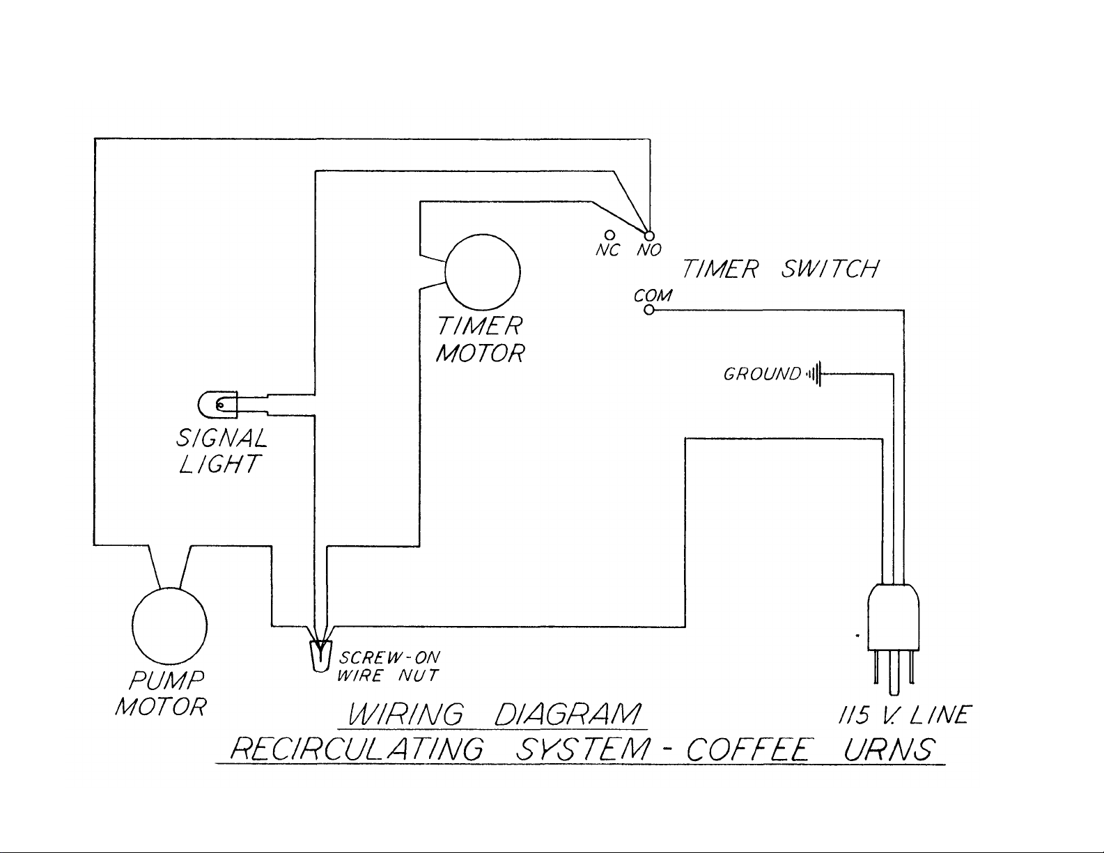
WIRING DIAGRAM E-4059
Page 4

COFFEE URNS
(Steam, Gas or Electric)
Note: Vulcan Coffee Urns are Vulcan Kettles modified to adapt them for the brewing of coffee. Basic instructions are
contained in the Kettle Manual and only those additional instructions required due to the modifications to the unit and
due to its use as a coffee urn are contained herein.
The modifications that adapt the kettle to the brewing of coffee are as follows:
1. Additions of the repour pump and its related piping, and its timer control.
2. Addition of the coffee holder (bag with holding frame or gridded riser, or stainless steel leacher.)
3. Change in type of draw off faucet.
4. Addition of graduated gage glass to show volume of water or brewed coffee.
5. Increased leg heighth to permit draw off faucet to discharge into tall containers.
OPERATING INSTRUCTIONS
See the "Notes for Operators" in the Kettle Manual. These all apply to the coffee urns excepting the cautions regarding the plug
type draw-off faucet used only on kettles.
SUGGESTED PROCEDURE FOR BREWING COFFEE
1. Turn heat on and if unit is thermostat controlled-gas and electric urns are always thermostat controlled-set thermostat dial
to 10.
2. Charge desired volume (up to brewing capacity but not less than one half of this capacity,) of water into the urn. The
graduated gage glass at the front of the urn shows the volume of water in the urn. Charging with hot water will shorten
the time required to heat the water.
3. Close cover and allow urn to bring water to a rolling boil. Then turn heat off (or set thermostat dial to 4 or 5).
4. Raise the cover, place the coffee holder in position and charge the proper amount of ground coffee (about one pound of
coffee to each 21/2 gallons of water).
Note: If a coffee bag is used, it must be wetted before its first use and
should be kept immersed in cold water when not in use. Once wetted,
never allow the bag to dry.
5. Close the cover, connect the union-in repour piping, open the observation hole cover, turn timer dial to desired brewing
time and press button at center of the timer dial to start the brewing cycle.
? 2 ?
Page 5

COFFEE URNS
SUGGESTED PROCEDURE FOR BREWING COFFEE (Continued)
6. At end of brewing time, allow approximately 5 minutes for coffee grounds to drain, then disconnect union at top of
vertical portion of repour line, open cover and remove holder and coffee grounds it holds.
7. Close cover, connect union and set timer dial to approximately 5 minutes to thoroughly mix brew. Brewed coffee is now
ready.
NOTES:
When timer dial is set to desired brewing time and button in center of dial is pressed to start the brewing cycle, the pointer on
dial will remain at the preset value. (Pointer does not return to 0.) To change this preset interval, the timer dial must be reset
manually.
The grind of coffee, the blend of coffee beans, the grade of coffee bag (if used), the gallons of water per pound of coffee
charged, and the length of the brewing cycle are all variables which affect the type of brew obtained. Individual tastes vary
widely as to the end result desired such that we can not offer specific recommendations covering these variables. Your coffee
vendor will offer valuable assistance to you in tailoring your procedure to produce the type of brew you desire.
The rate of repouring is controlled by the size of orifice hole in the metering disc assembled inside the shower head. Three
discs are supplied, one with a 5/32" orifice hole, one with a 11/64" orifice hole, and one with a 3/16" orifice hole. Use the disc
with the largest orifice hole possible without causing flooding with your selected operating conditions. One of the metering
discs may be modified to provide a larger or smaller orifice hole if such is found desirable. For your information, flow rates are
approximately as follows:
With 5/32" orifice hole disc - 1.6 gal/min.
With 11/64" orifice hole disc - 1.9 gal/min.
With 3/16" orifice hole disc - 2.3 gal/min.
With metering disc omitted - 7. 6 gal/min.
We suggest a brewing time of 15 to 25 minutes.
Clean and flush the urn immediately after use. The pipe lines and pump are cleaned by using the pump to circulate the cleaning
solution. Prompt, careful cleaning is essential to assure absence of any build up which could adversely affect the taste of the
brew. Periodically, as found necessary in your operation, dismantle the pump, the repour piping and the faucet and clean them
thoroughly.
One pound of ground coffee will absorb and retain approximately one quart of water. Therefore, for each 10 gallons of water
charged, you will get approximately 9 gallons of brewed coffee.
- 3 -
Page 6

COFFEE URNS
Service Instructions
TO REPLACE TIMER:
Remove four (4) screws from corners of timer face plate and pull timer unit forward out of box.
TO REPLACE SIGNAL LIGHT:
Remove eight (8) screws around edges of box. The front should then be slipped out of box. Remove two (2) screws from either
side of signal light. Note position of bar of signal light and gasket. Replace with parts in same position, bar against back
surface of metal ring on light and gasket around light and between metal ring and inner surface of timer box wall.
TO REPLACE PUMP PARTS:
Remove tube between faucet flange and pump body. Disconnect tube nut at discharge opening of pump-body. Remove two
thumb nuts on the pump body and pull pump body forward.
TO REPLACE IMPELLER:
Strike impeller sharply in counter-clockwise direction with soft instrument, such as a rawhide mallet or block of wood, to
disengage from locking pin of shaft. Pull forward to remove.
TO REPLACE "O" RING GASKET:
Remove gasket from groove in inboard head. This service indicated when leak is observed which cannot be stopped by
tightening thumb nuts on pump body. The impeller need not be removed to perform this service.
TO ADJUST OR REPLACE SHAFT SEAL:
This service is indicated when a drip is observed from drain hole in bottom of bracket housing. Remove impeller by following
aforementioned directions, then slip inboard head forward and off of shaft. Loosen set screw in adjusting collar and slip collar
and seals forward slightly. Tighten set screw and remove inboard head. When inboard head is seated solidly in bracket, the
rubber shaft seal should be compressed 1/32 inch.
TO REPLACE PUMP MOTOR:
Follow instruction for replacing pump parts above. Remove impeller, inboard head and rotary seal from pump. Remove three
cap nuts from front of bracket housing and slip motor out from rear of housing. Loosen set screw in impeller shaft to remove it
from pump shaft. Reassemble in reverse order.
TO REPLACE PIPE LINE GASKETS:
Disengage union nut, remove old gasket from female portion of joint and snap in new gasket.
Note: When re-engaging union nut on any gasketed joint, be careful not to
overtighten. Over tightening will contribute to rapid breakdown of the
gaskets.
TO REPLACE SEAT CUP IN DRAW-OFF FAUCET:
Unscrew complete black plastic bonnet and pull out of faucet body. Pull seat cup off of bonnet assembly. When reassembling,
be careful to have mushroom end of shaft properly seated in recessed portion of bottom of seat cup.
- 4 -
Page 7

WIRING DIAGRAM E-4059
Page 8

PARTS DRAWING H-3922
- 6 -
Page 9

PARTS LIST
ITEM PART NO. REQ'D PART NAME
1 3919 1 Draw-off Faucet
2 3917 1 Flange
3 3918 1 Gasket - Flange
4 3497 2 Flange Mntg. Screw (5/8-18 NF x 1" LG. Hex. Hd.)
5 3750 3 1 1/2" Snap-Tite Gasket
6 3745 3 1 1/2" To 1" Ferrule
7 3775 3 1 1/2" Nut
8
3923-2
9 4382 1 Motor - 1/3 HP., 60 CY. 11 1 PH., 115V.
10 3819 3 Motor Stud
11 3694 1 Bracket Housing
12 3776 3 Motor Stud Nut
13 3809 1 Impeller Shaft
14 3704 1 Adjusting Collar
15 3805 1 Rubber Seal
16 3806 1 Rotary Seal
17 3761 1 Inboard Head
18 3748 1 "0" - Ring Gasket
19 3760 1 Impeller
20 3777 1 Outboard Head
21 3820 2 Head Stud
22
23 3678 1 Pump Mounting Plate
24 3679 4 Pump Mntg. Screw (5/8 – 11 NC x 3/4" LG. Ilex. Hd.)
25
26 3696 1 Pipe Hanger
27 3774 3 1" Nut
28 3743 3 1 " Ferrule
29 3749 3 1 " Snap-Tite Gasket
30 3725 1 1" Elbow - 90°
31
3924-9 or 1 " “ - 60 "
32 3726 1 Flanged Elbow - 90°
33 3747 3 Rubber Gasket - Shower Head
34 3895
35 3897
36
3896-2
37 3810
38 3493-6
39 3493-7 1 Drain Cock
3923-1 Or 1 Flange To Pump Tubing - 30 Gal.
Or 1
3923-3 Or 1 " “ - 60 "
3923-4 1 " “ - 75, 100 & 125 Gal.
3924-1 1 Pump outlet Tubing - 30 Gal.
3924-2 or “ “ “ - 45 "
3924-3 or 1 “ “ “ - 60 "
3924-4 3924-5 or ^ “ “ “ - 100"
3924-6 or 1 “ “ “ - 125"
3924-7 1 Shower Head Inlet Tubing - 30 Gal.
3924-8 or 1 “ “ - 45 "
3924-10 or 1 " “ - 75, 100 & 125 Gal.
2 Head Stud Nut
or 1 “ “ “ - 75”
1
1
3896-1
1
1
3896-3
1
1
1
“ “ -45”
Tin Gasket - Shower Head
Disc Hold-Down Strip
Metering Disc - 5/32" Hole
“ “ 11/64" Hole
“ “ 3/16" Hole
Shower Head
Lower Gauge Glass Faucet
- 7 -
Page 10

PARTS LIST (cont.)
ITEM PART NO. REQ'D PART NAME
40 3493-5 1 Rubber Seal
41 3493-4 1 Washer
42 3493-2 1 Compression Nut
43
44
45 2665 1 Angle Nut
3912-1 1 Gauge Glass - 30 Gal.
3912-2 1 “ “ - 45, 60 & 75 Gal.
3912-3 or 1 “ “ - 100 Gal.
3912-4 or 1 “ “ - 125 "
3911-1 or1 Graduated Angle Ass'y. - 30 Gal.
3911-2
3911-3 Or 1 “ “ - 100 Gal.
3911-4 Or 1 “ “ - 125 "
3794 1 Motor & Pump Ass'y,, - Complete
“ “ - 45, 60 & 75 Gal.
TIMER PARTS (NOT SHOWN IN DRAWING)
3894 1 Timer - Recirculating System
3393-R 1 Signal Light - Red.
3674 1 Signal Light Bracket
3483 1 Signal Light Gasket
2462 Bracket & Timer Mntg. Screw
3484 " " " Lockwasher
FAUCET PARTS (NOT SHOWN IN DRAWING)
4073 Seat Cup (Sealing Membrane)
BAG HOLDER PARTS (NOT SHOWN IN DRAWING)
Model C-30
3955-1 - Bag Holder
3938-1 - Locking Ring
4065-1 - Lift Bar
3684 - Coffee Bag
Model C-45
3955-2 - Bag Holder
3938-2 - Locking Ring
4065-2 - Lift Bar
3685 - Coffee Bag
Model C-60
3955-3 - Bag Holder
3938-3 - Locking Ring
4065-3 - Lift Bar
3686 - Coffee Bag
Models C-75, C-100 & C-125
3955-4 - Bag Holder
3938-4 - Locking Ring
4065-4 - Lift Bar
3686 - Coffee Rag
- 8 -
 Loading...