

Page 1
SERVICE MANUAL
FULL SIZE GAS CONVECTION
OVEN
VC5GD
- NOTICE -
This Manual is prepared for the use of trained Vulcan Service
Technicians and should not be used by those not properly
qualified.
This manual is not intended to be all encompassing. If you have
not attended a Vulcan Service School for this product, you should
read, in its entirety, the repair procedure you wish to perform to
determine if you have the necessary tools, instruments and skills
required to perform the procedure. Procedures for which you do
not have the necessary tools, instruments and skills should be
performed by a trained Vulcan Service Technician.
The reproduction, transfer, sale or other use of this Manual,
without the express written consent of Vulcan, is prohibited.
This manual has been provided to you by ITW Food Equipment
Group LLC ("ITW FEG") without charge and remains the property
of ITW FEG, and by accepting this manual you agree that you will
return it to ITW FEG promptly upon its request for such return at
any time in the future.
A product of Vulcan-Hart 3600 North Point Blvd Baltimore, MD 21222
F45598 (0616)
Page 2

FULL SIZE GAS CONVECTION OVEN
TABLE OF CONTENTS
GENERAL .................................................................................................. 3
INTRODUCTION ....................................................................................... 3
OPERATION ........................................................................................... 3
INSTALLATION ........................................................................................ 3
LUBRICATION ......................................................................................... 3
CLEANING ............................................................................................. 3
SPECIFICATIONS ...................................................................................... 3
TOOLS ................................................................................................. 4
REMOVAL AND REPLACEMENT OF PARTS ............................................................... 5
COVERS AND PANELS ................................................................................ 5
CONTROL PANEL COMPONENTS ..................................................................... 6
COMPONENT PANEL COMPONENTS ................................................................. 7
TEMPERATURE PROBE ............................................................................... 7
GAS BURNER ......................................................................................... 8
GAS ORIFICE .......................................................................................... 9
GAS SOLENOID VALVE ................................................................................ 9
IGNITION CONTROL MODULE ....................................................................... 10
SPARK IGNITER AND FLAME SENSE ................................................................ 10
BLOWER ............................................................................................. 11
MOTOR ............................................................................................... 12
DOOR SWITCH ....................................................................................... 13
ROLLER LATCH ASSEMBLY (INDEPENDENT DOORS) ............................................... 14
DOOR REMOVAL ..................................................................................... 14
HIGH LIMIT THERMOSTAT ........................................................................... 14
INTERIOR LIGHTS .................................................................................... 15
COOLING FAN ........................................................................................ 15
SERVICE PROCEDURES AND ADJUSTMENTS ........................................................... 17
TEMPERATURE CONTROL CALIBRATION ........................................................... 17
SOLID STATE TEMPERATURE CONTROL TEST ..................................................... 18
TEMPERATURE CONTROL BOARD FAULT INDICATOR .............................................. 18
TEMPERATURE PROBE TEST ....................................................................... 19
GAS VALVE PRESSURE CHECK ..................................................................... 19
VERIFICATION OF SPARK AT IGNITOR .............................................................. 20
BLOWER ADJUSTMENT .............................................................................. 20
DOOR STRIKE ADJUSTMENT INDEPENDENT DOORS) .............................................. 21
ELECTRICAL OPERATION ................................................................................ 22
COMPONENT FUNCTION ............................................................................ 22
COMPONENT LOCATION ............................................................................. 23
SEQUENCE OF OPERATION ......................................................................... 28
DIAGRAMS ............................................................................................... 31
WIRING DIAGRAM AND SCHEMATIC ................................................................. 31
TROUBLESHOOTING ..................................................................................... 34
ALL MODELS ......................................................................................... 34
© VULCAN 2016
F45598 (0616) Page 2 of 35
Page 3
FULL SIZE GAS CONVECTION OVEN - GENERAL
GENERAL
INTRODUCTION
Models
MODEL
VC5GD 26.5" Solid State
1
Simultaneous doors are optional (with or w/o window).
2
Stainless steel doors with window (standard).
CAVITY DEPTH
TEMPERATURE
FEATURES
CONTROL
DOORS
(50/50)
Independent 1
2
OPERATION
Refer to Operator's manual for operation instructions
(F31123), located on Vulcan Resource Center.
https://my.vulcanfeg.com/resourcecenter/
vulcanwolfberkel/default.aspx
INSTALLATION
Detailed installation instructions (F31123) are located
on the Vulcan resource center.
https://my.vulcanfeg.com/resourcecenter/
vulcanwolfberkel/default.aspx
SPECIFICATIONS
Voltage Amps
120/60/1 8.0
Input BTU Rating
Fuel BTU
Natural Gas 50,000 input at 5 in. W.C.
Propane 50,000 input at 10.0 in. W.C.
LUBRICATION
Refer to Lubrications Manual F20067 for current
values.
CLEANING
Refer to Operator's manual for cleaning instructions,
located on Vulcan Resource Center.
https://my.vulcanfeg.com/resourcecenter/
vulcanwolfberkel/default.aspx
Electrical
Gas Line Pressures
Fuel Recommended Minimum (in. W.C.) Recommended Maximum (in. W.C.)
Natural Gas 8.0, 6.0 14.0
Propane 11.0 14.0
Page 3 of 35 F45598 (0616)
Page 4

FULL SIZE GAS CONVECTION OVEN - GENERAL
TOOLS
Standard
• Standard set of Hand Tools.
• VOM with minimum of NFPA-70E CATIII 600V,
UL/CSA/TUV listed. Sensitivity of at least 20,000
ohms per volt and the ability to measure DC
micro amps. Meter leads must also be rated at
CAT III 600V.
• Clamp on type amp meter with minimum of
NFPA-70E CAT III 600V,UL/CSA/TUV listed.
Special
• Temperature Tester (Thermocouple Type).
• Manometer.
F45598 (0616) Page 4 of 35
Page 5
FULL SIZE GAS CONVECTION OVEN - REMOVAL AND REPLACEMENT OF PARTS
REMOVAL AND REPLACEMENT OF PARTS
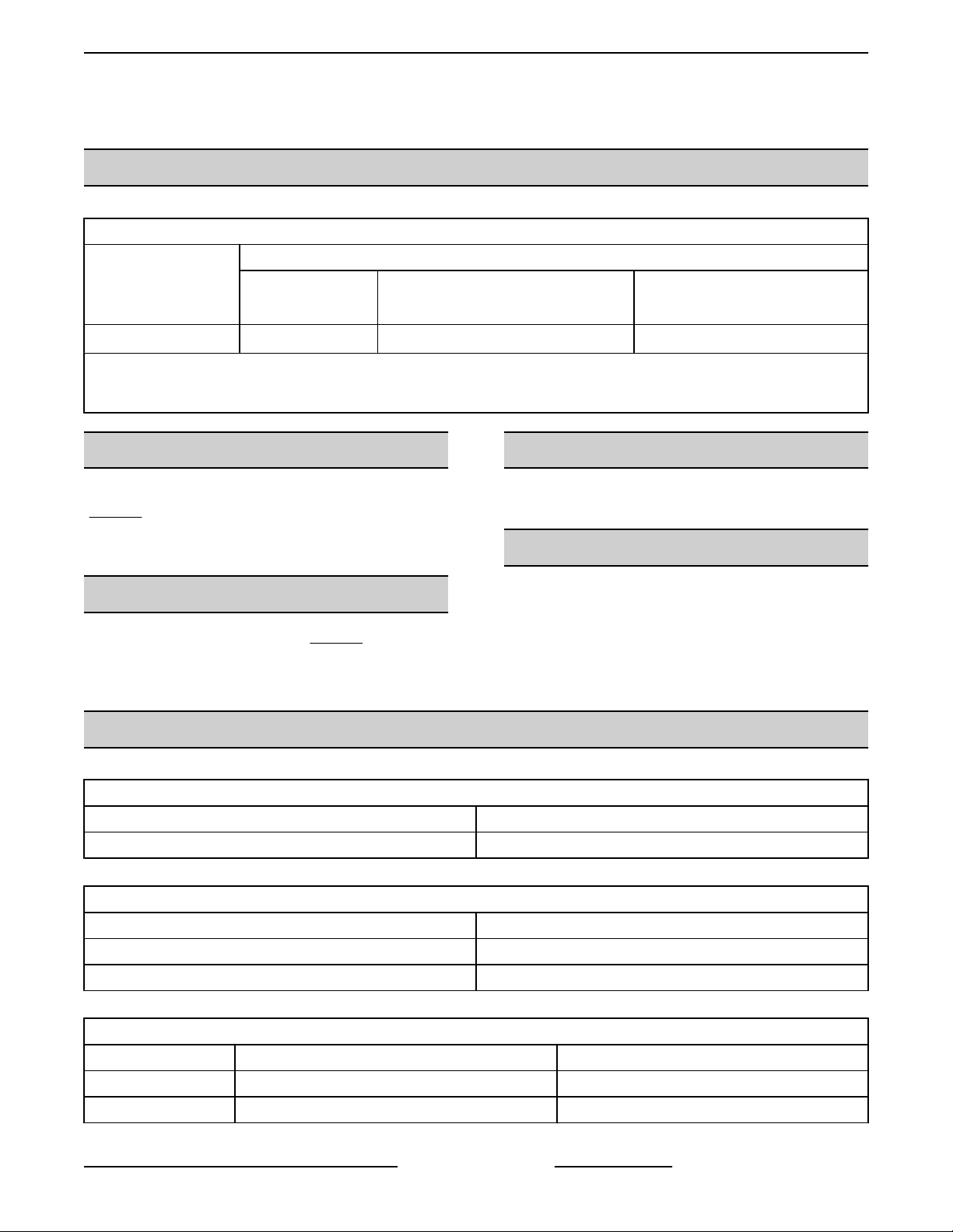
COVERS AND PANELS
Disconnect the
electrical power to the machine and
follow lockout / tagout procedures.
Bottom Front Cover
1. Remove four screws, two from each side of
bottom cover, then remove cover from oven.
Fig. 1
2. Reverse procedure to install. Verify bottom cover
is seated under front plate.
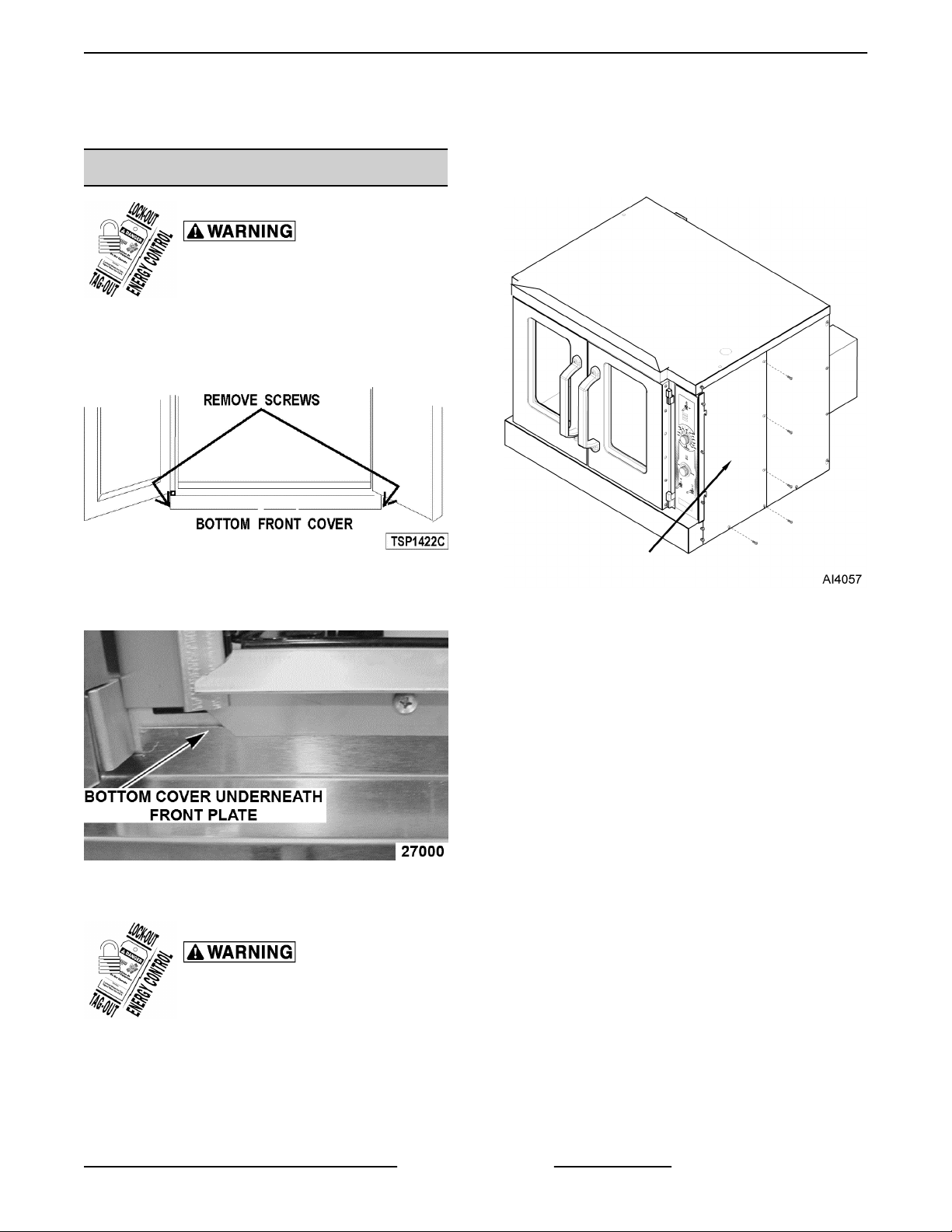
3. Remove screws along right side and bottom of
front panel.
Fig. 3
4. Slide right side front panel out.
Fig. 2
Right Side - Front Panel
Disconnect the
electrical power to the machine and
follow lockout / tagout procedures.
1. Loosen two screws near front of oven, which
secure bottom front cover.
2. Loosen screws on left side of front panel and top
cover screw.
5. Reverse procedure to install.
Right Side - Rear Panel
1. Remove two middle screws along right side of
rear panel.
2. Remove screws along left side of rear panel.
3. Remove bottom screws on rear panel.
4. Loosen top and bottom screw along right side of
rear panel.
Page 5 of 35 F45598 (0616)
Page 6
FULL SIZE GAS CONVECTION OVEN - REMOVAL AND REPLACEMENT OF PARTS
Control Panel
1. Remove three screws on the right side which
secure the control panel then left up and pull
away.
Fig. 4
5. Slide right side rear panel up and to the right to
remove.
6. Reverse procedure to install.
Left Side Panel
1. Remove screws along right side, middle left side,
and bottom on left side panel.
2. Loosen screws on top and bottom on left side of
panel.
3. Loosen two screws near front of oven, which
secure bottom front cover.
Fig. 6
2. Disconnect the temperature probe leads from the
solid state temperature control.
3. Unplug the wire harnesses connector to control
panel components.
4. Unplug Ground wire from control panel.
5. Reverse procedure to install.
CONTROL PANEL COMPONENTS
Disconnect the
electrical power to the machine and
follow lockout / tagout procedures.
1. Remove CONTROL PANEL.
2. Remove component being replaced.
3. Reverse procedure to install replacement
4. Check oven for proper operation.
Fig. 5
4. Lift up and pull away to remove.
5. Reverse procedure to install.
F45598 (0616) Page 6 of 35
component.
Page 7
FULL SIZE GAS CONVECTION OVEN - REMOVAL AND REPLACEMENT OF PARTS
TEMPERATURE PROBE
Disconnect the
electrical power to the machine and
follow lockout / tagout procedures.
1. Remove RIGHT SIDE PANEL.
NOTE: If right side - front panel is not accessible, this
component can be serviced by removing CONTROL
PANEL.
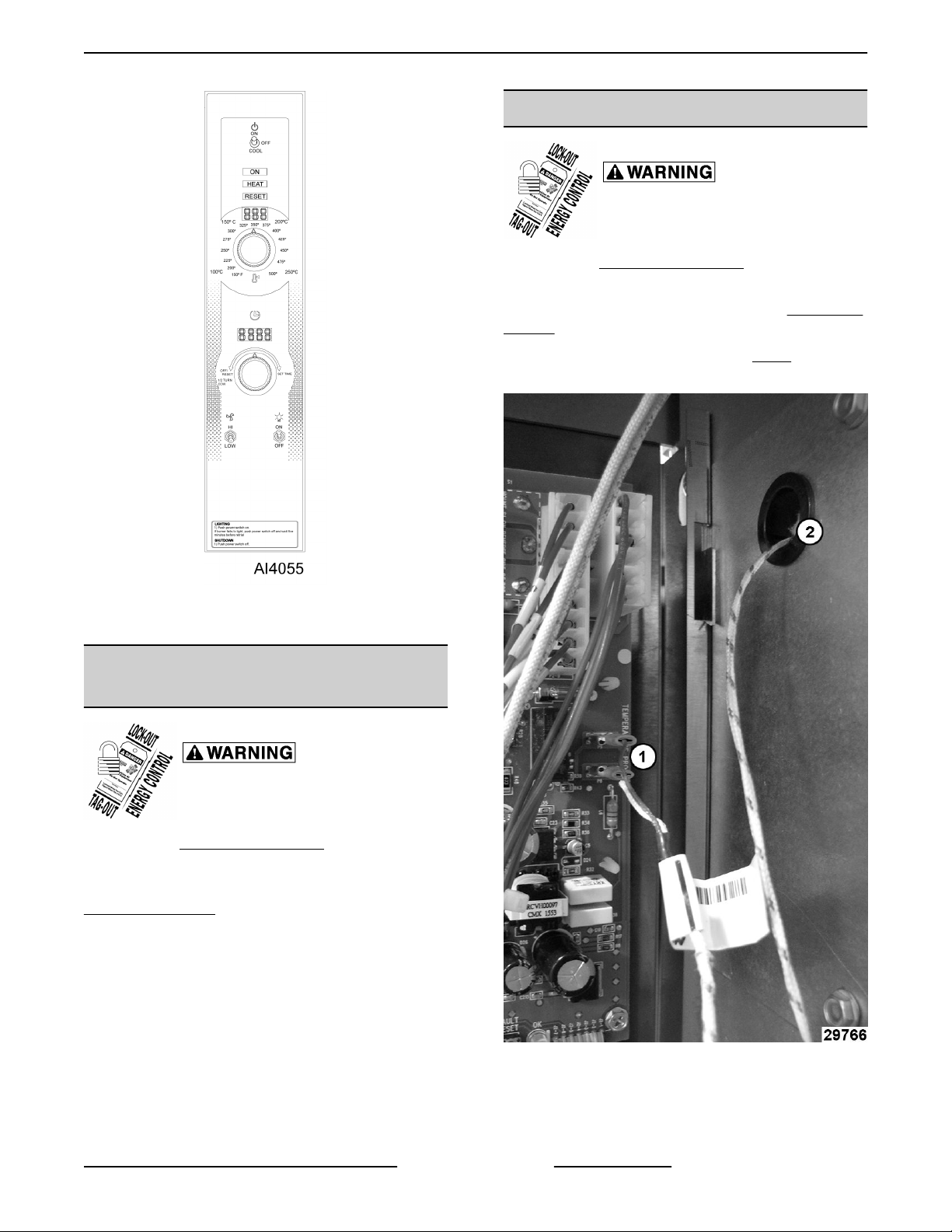
2. Disconnect the probe leads (1, Fig. 8) from the
solid state temperature control.
Fig. 7
NOTE: Panel with standard controls shown.
COMPONENT PANEL
COMPONENTS
Disconnect the
electrical power to the machine and
follow lockout / tagout procedures.
1. Remove
NOTE: If right side panel is not accessible, this
component can be service by removing the
CONTROL PANEL.
2. Disconnect the wire leads to component being
replaced.
3. Remove the component.
4. Reverse procedure to install component.
5. Check oven for proper operation.
RIGHT SIDE PANEL.
Fig. 8
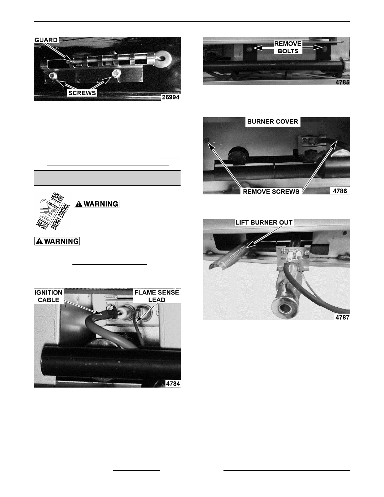
3. Remove the racks from inside cavity.
4. Remove the probe guard.
Page 7 of 35 F45598 (0616)
Page 8
FULL SIZE GAS CONVECTION OVEN - REMOVAL AND REPLACEMENT OF PARTS
Fig. 11
Fig. 9
5. Remove probe by pushing it through the oven
wall opening (2, Fig. 8) in control panel area.
6. Reverse the procedure to install the replacement
probe.
7. Adjust the temperature control. Refer to: SOLID
STATE TEMPERATURE CONTROL TEST .
GAS BURNER
Disconnect the
electrical power to the machine and
follow lockout / tagout procedures.
Shut off the gas before servicing the
unit.
1. Remove
2. Disconnect ignition cable and the flame sense
lead wire.
BOTTOM FRONT COVER.
4. Remove screws securing the burner cover and
pull straight out.
Fig. 12
5. Grasp burner and lift out.
6. Reverse procedure to install replacement burner.
NOTE: Ensure that burner positioning bracket (Ushaped end) is inserted into slot at the rear of burner
chamber.
7. Check for proper operation.
Fig. 10
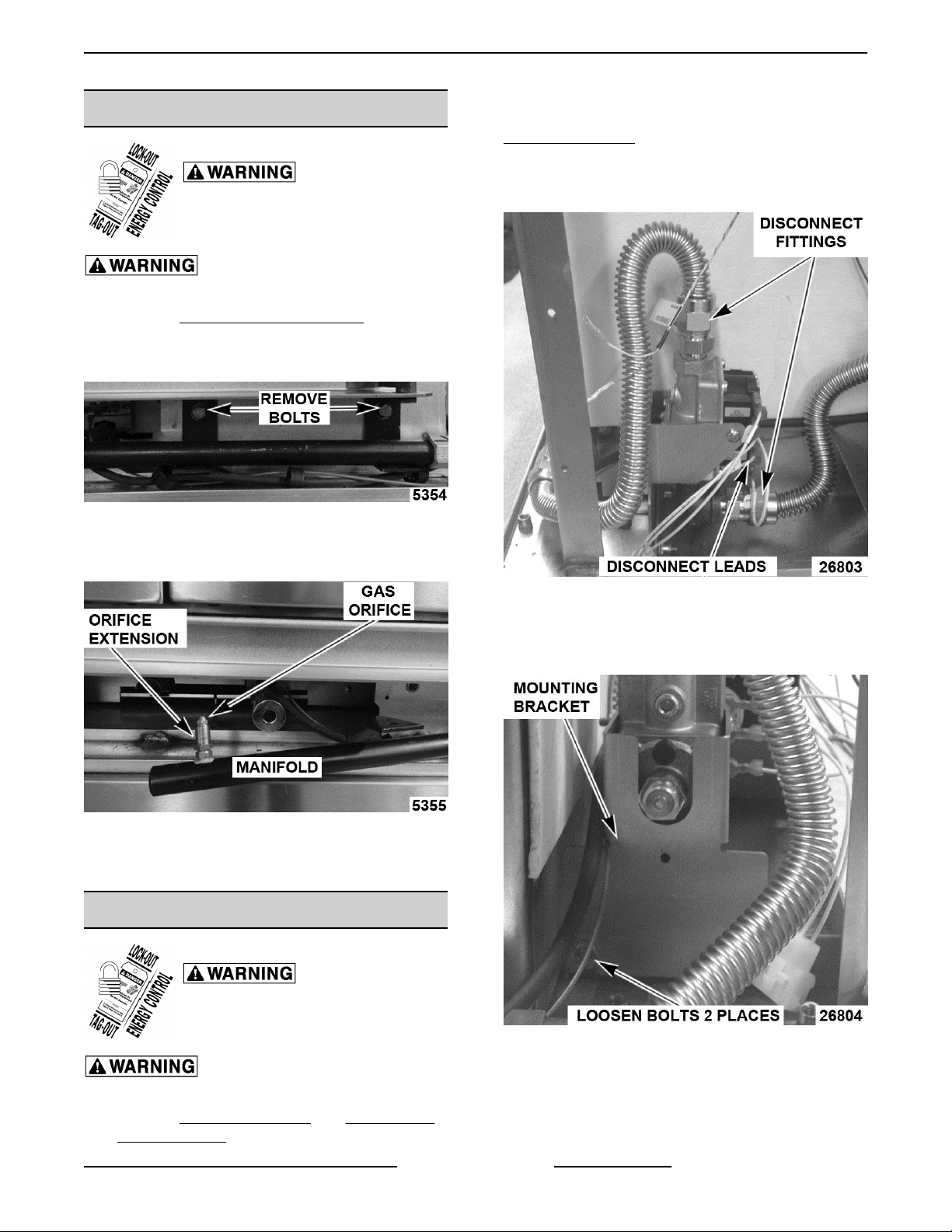
3. Remove bolts securing gas manifold to oven and
place manifold to the side.
F45598 (0616) Page 8 of 35
Fig. 13
Page 9
FULL SIZE GAS CONVECTION OVEN - REMOVAL AND REPLACEMENT OF PARTS
GAS ORIFICE
Disconnect the
electrical power to the machine and
follow lockout / tagout procedures.
Shut off the gas before servicing the
unit.
1. Remove
2. Remove bolts securing gas manifold to oven and
place manifold to the side.
3. Remove gas orifice from spud on manifold and
replace with correct orifice for the given altitude.
BOTTOM FRONT COVER.
Fig. 14
NOTE: if right side panel is not accessible, this
component can be serviced by just removing
CONTROL PANEL.
2. Disconnect lead wires.
3. Disconnect compression fittings to valve.
Fig. 15
4. Reverse procedure to install and check for proper
operation.
GAS SOLENOID VALVE
Disconnect the
electrical power to the machine and
follow lockout / tagout procedures.
Fig. 16
4. Loosen bolts securing valve and bracket
assembly then remove screws securing valve to
bracket.
Fig. 17
Shut off the gas before servicing the
unit.
1. Remove CONTROL PANEL and RIGHT SIDE
FRONT PANEL.
5. Reverse procedure to install replacement gas
valve.
Page 9 of 35 F45598 (0616)
Page 10
FULL SIZE GAS CONVECTION OVEN - REMOVAL AND REPLACEMENT OF PARTS
NOTE: Clean pipe threads and apply pipe joint
compound to threads. Any pipe joint compound used,
must be resistant to the action of propane gases.
All gas joints disturbed during
servicing must be checked for leaks. Check with a
soap and water solution (bubbles). Do not use an open
flame.
6. Verify gas pressure as outlined under GAS
PRESSURE ADJUSTMENT.
7. Check for proper operation.
IGNITION CONTROL MODULE
Disconnect the
electrical power to the machine and
follow lockout / tagout procedures.
Shut off the gas before servicing the
unit.
1. Remove RIGHT SIDE FRONT PANEL.
SPARK IGNITER AND FLAME
SENSE
Disconnect the
electrical power to the machine and
follow lockout / tagout procedures.
Shut off the gas before servicing the
unit.
1. Remove GAS BURNER.
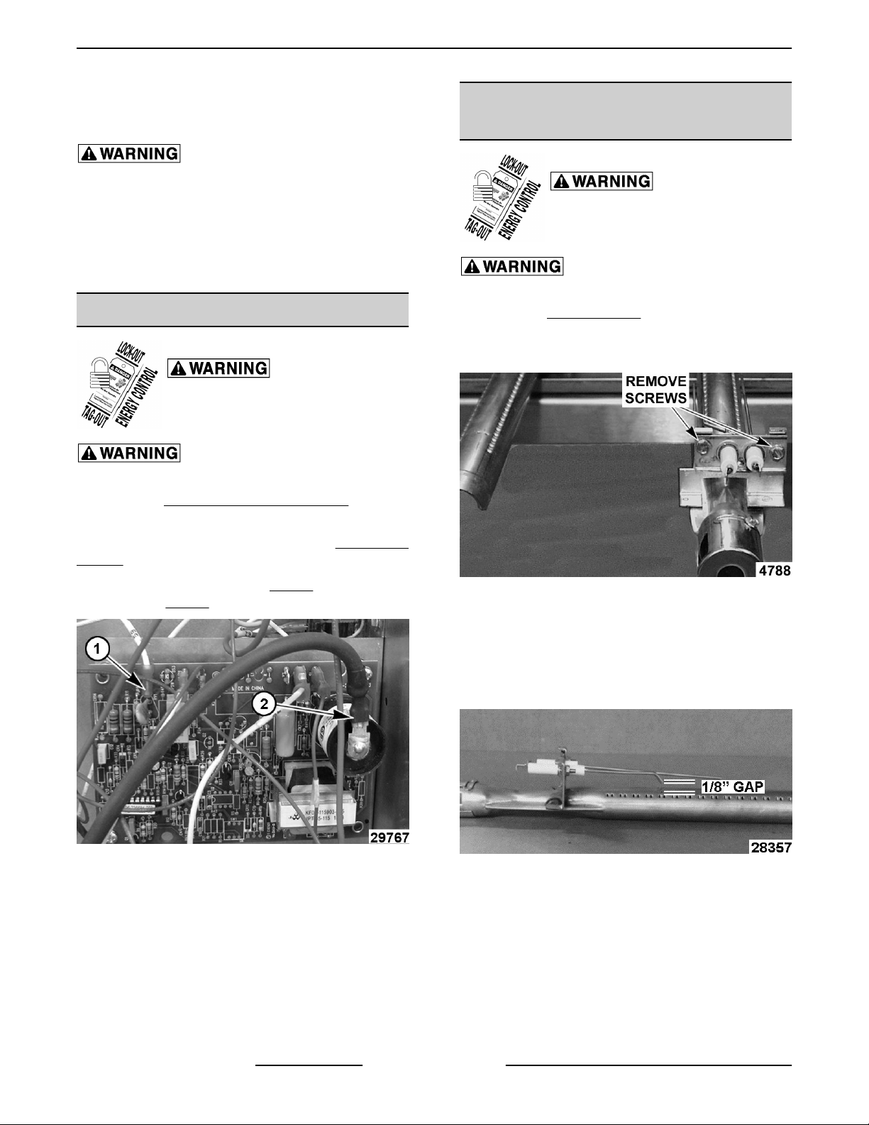
2. Remove screws securing ignitor and flame sense
to burner, then remove assembly.
NOTE: If right side panel is not accessible, this
component can be serviced by removing CONTROL
PANEL.
2. Disconnect lead wires (1, Fig. 18) and igniter
cable (2, Fig. 18) from ignition module board.
Fig. 18
3. Remove the ignition module board from the
mounting bracket.
4. Reverse the procedure to install replacement
ignition module board.
Fig. 19
3. Reverse procedure to install assembly and check
for proper operation.
NOTE: Check to ensure spark gap distance is
approximately 1/8". If gap appears to be excessive or
poor sparking is occurring, then adjust.
Fig. 20
F45598 (0616) Page 10 of 35
Page 11
FULL SIZE GAS CONVECTION OVEN - REMOVAL AND REPLACEMENT OF PARTS
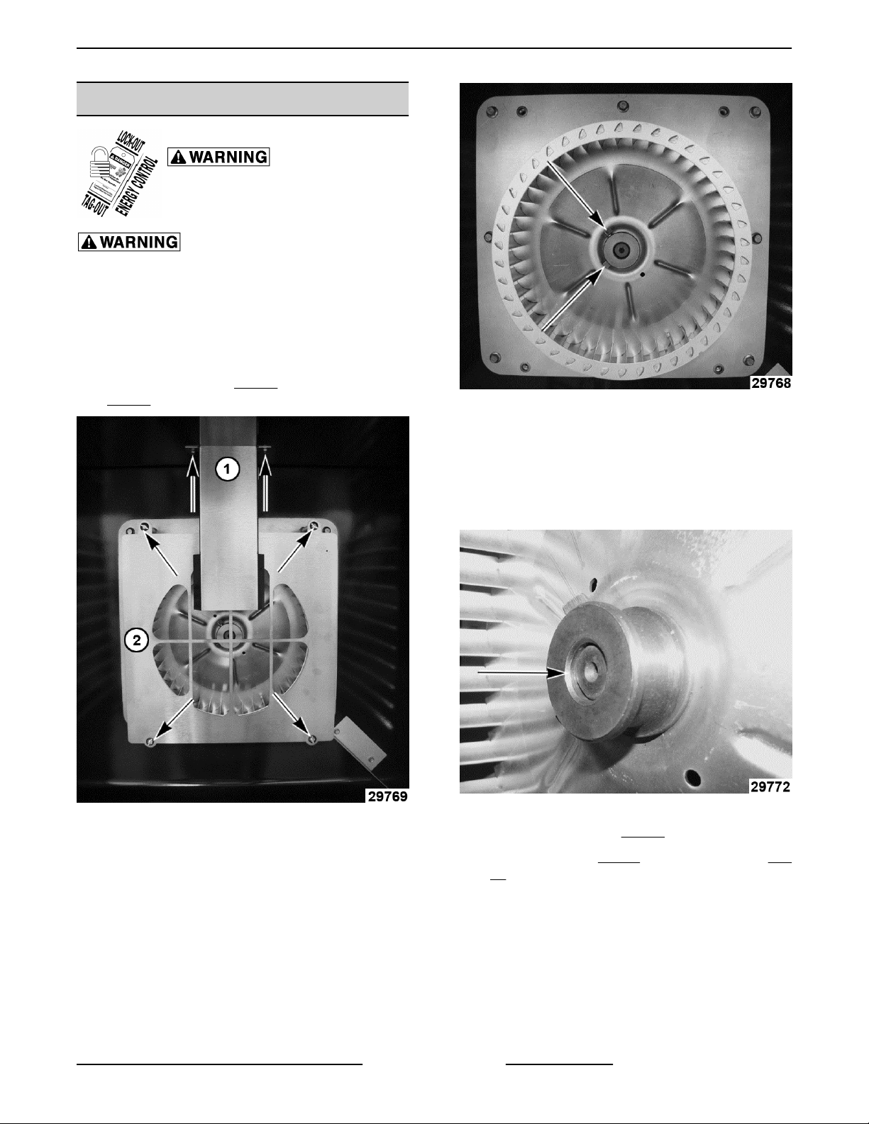
BLOWER
Disconnect the
electrical power to the machine and
follow lockout / tagout procedures.
Shut off the gas before servicing the
unit.
Removal
1. Remove racks.
2. Lay cardboard on bottom of oven cavity to protect
surface.
3. Remove snorkel (1,
Fig. 21) mounting screws.
Fig. 21) and baffle panel (2,
Fig. 22
5. Remove blower from motor shaft using a bearing
puller.
Installation
1. Slide blower onto motor shaft until hub is
protruding 1/8".
Fig. 21
4. Loosen set screws on blower hub.
Fig. 23
2. Tighten set screws ( Fig. 22) on blower hub.
3. Install snorkel (1, Fig. 21) and baffle panel (2, Fig.
21).
4. Install racks.
5. Check oven for proper operation.
Page 11 of 35 F45598 (0616)
Page 12

unit.
FULL SIZE GAS CONVECTION OVEN - REMOVAL AND REPLACEMENT OF PARTS
MOTOR
Disconnect the
electrical power to the machine and
follow lockout / tagout procedures.
Shut off the gas before servicing the
1. Remove
2. Remove nuts (1, Fig. 24) that secure the motor
mounting plate to rear wall.
3. Pull motor assembly into oven cavity and place it
on cardboard.
BLOWER.
Fig. 24
Fig. 25
8. Slide blower onto motor shaft until hub is
protruding 1/8".
4. Remove junction box cover on motor, disconnect
lead wires and remove conduit.
5. Remove motor mounting bolts and flat washers
then lift the motor from mounting plate.
6. Position replacement motor on motor mounting
plate and install mounting bolts and washers.
Hand tighten mounting bolts only.
7. Reconnect lead wires at motor, replace conduit
and junction box cover.
NOTE: Check data plate on motor for wiring
schematic. Motor must rotate clockwise when viewed
from shaft end.
F45598 (0616) Page 12 of 35
9. Tighten set screws.
Fig. 26
Page 13

FULL SIZE GAS CONVECTION OVEN - REMOVAL AND REPLACEMENT OF PARTS
10. Adjust motor position until blower is parallel to
motor mounting plate as outlined under
BLOWER ADJUSTMENT.
DOOR SWITCH
Disconnect the
electrical power to the machine and
follow lockout / tagout procedures.
1. Remove BOTTOM FRONT COVER.
2. Unscrew nut holding door switch.
3. Pull door switch and washer out through bottom
panel opening.
11. Install motor mounting plate.
12. Install snorkel (1, Fig. 28) and baffle panel (2, Fig.
28).
Fig. 29
Fig. 28
13. Remove cardboard from the bottom of the oven
cavity.
14. Install racks.
15. Check oven for proper operation.
Page 13 of 35 F45598 (0616)
4. Disconnect lead wires to door switch.
5. Reverse procedure to install replacement switch.
Page 14

FULL SIZE GAS CONVECTION OVEN - REMOVAL AND REPLACEMENT OF PARTS
ROLLER LATCH ASSEMBLY
(INDEPENDENT DOORS)
Disconnect the
electrical power to the machine and
follow lockout / tagout procedures.
1. Remove screws that attach roller latch assembly
to door.
3. Reverse procedure to install the replacement
door.
4. Check oven for proper operation.
HIGH LIMIT THERMOSTAT
Disconnect the
electrical power to the machine and
follow lockout / tagout procedures.
1. Remove racks.
2. Remove high limit thermostat cover/mounting
plate from inside oven cavity at the top.
Fig. 30
2. Reverse procedure to install.
DOOR REMOVAL
1. Open door to a 90° angle.
2. Lift door up off hinges to remove.
Fig. 32
3. Disconnect lead wires from high limit thermostat.
NOTE: Remove old RTV sealer from cover and
mating surfaces inside oven cavity and apply new high
temperature RTV sealer before installing.
4. Reverse procedure to install.
Fig. 31
F45598 (0616) Page 14 of 35
Page 15

FULL SIZE GAS CONVECTION OVEN - REMOVAL AND REPLACEMENT OF PARTS
INTERIOR LIGHTS
Disconnect the
electrical power to the machine and
follow lockout / tagout procedures.
Do not touch the Halogen lamp with bare
hands. If lamp is exposed to oil from the skin, the life
will be reduced. Ensure lamp is free from oil and dirt
before replacing.
Bulb Replacement
1. Pull lamp cover off.
2. Grasp lamp using a clean cloth and remove from
lamp assembly.
Fig. 33
3. Reverse procedure to install new bulb.
Fig. 34
4. Disconnect wires.
5. Reverse procedure to install new lamp assembly.
COOLING FAN
Disconnect the
electrical power to the machine and
follow lockout / tagout procedures.
1. Remove
NOTE: If right side - front panel is not accessible, this
component can be serviced by removing CONTROL
PANEL.
2. Remove wire nuts from fan wire connections.
RIGHT SIDE FRONT PANEL.
Lamp Assembly Replacement
1. Remove racks.
2. Pull lamp cover off.
3. Remove RIGHT SIDE REAR PANEL.
Insert screw driver and push lamp assembly out
into cavity.
Page 15 of 35 F45598 (0616)
Page 16

FULL SIZE GAS CONVECTION OVEN - REMOVAL AND REPLACEMENT OF PARTS
Fig. 35
3. Loosen tab screw holding fan to component
panel.
4. Rotate tab so that fan will clear and remove fan.
5. Reverse procedure to install fan and check for
proper operation.
NOTE: Fan must be installed so air is pulled from
outside the rear of oven and blown into control area.
The arrow on the fan body indicates "air flow" direction
and should be pointing toward controls.
F45598 (0616) Page 16 of 35
Page 17

FULL SIZE GAS CONVECTION OVEN - SERVICE PROCEDURES AND ADJUSTMENTS
SERVICE PROCEDURES AND ADJUSTMENTS
TEMPERATURE CONTROL
CALIBRATION
Certain procedures in
this section require electrical test or
measurements while power is applied
to the machine. Exercise extreme
caution at all times and follow Arc Flash
procedures. If test points are not easily
accessible, disconnect power and
follow Lockout/Tagout procedures,
attach test equipment and reapply
power to test.
NOTE: The temperature control module has a
programmable offset that can be applied to the set
temperature. This can be adjusted in 5 degree
increments up to 20 degrees in either direction.
1. Place a thermocouple in center of oven cavity.
2. Remove RIGHT SIDE FRONT PANEL to view
back of temperature control board.
1. Remove temperature control knob.
3. Turn oven on and set to 350° Fahrenheit.
4. Watch the red fault indicator. If light comes on
see TEMPERATURE CONTROL BOARD
FAULT INDICATOR for troubleshooting tips. If
light stays off go to next step.
5. Allow oven to stabilize (typically 3 cycles)
6. Record temperature when heat light goes off and
comes on for at least 2 cycles.
7. Calculate differential by subtracting temperature
when lamp goes out from temperature when
lamp comes on.
Differential = (Heat Lamp OFF - Heat Lamp ON)
• If differential is less than 20 degrees,
temperature control circuit is functioning
properly. If it is more turn off oven and replace
TEMPERATURE PROBE.
• Repeat CALIBRATION steps. Calculate average
temperature (Heat Lamp OFF temperature +
Heat Lamp ON temperature divided by 2).
Average = (Heat Lamp OFF + Heat lamp on divided
by 2)
• If Average is less than 10° Fahrenheit from dial
setting, thermostat is properly calibrated.
• If it is more than 10° Fahrenheit, then complete
following steps.
Fig. 36
2. Press and hold both + (plus) and the –
(minus) buttons for 3 seconds.
NOTE: Power light will start blinking and display will
show current offset.
Page 17 of 35 F45598 (0616)
Page 18

FULL SIZE GAS CONVECTION OVEN - SERVICE PROCEDURES AND ADJUSTMENTS
3. Push “+” or “-“ button to increase or
decrease offset.
NOTE: Each press will change offset by 5 degrees.
NOTE: After 5 seconds of no activity controller will
automatically exit calibration mode.
SOLID STATE TEMPERATURE
CONTROL TEST
Certain procedures in
this section require electrical test or
measurements while power is applied
to the machine. Exercise extreme
caution at all times and follow Arc Flash
procedures. If test points are not easily
accessible, disconnect power and
follow Lockout/Tagout procedures,
attach test equipment and reapply
power to test.
1. Remove RIGHT SIDE FRONT PANEL.
NOTE: If right side panel is not accessible, this
component can be serviced by removing CONTROL
PANEL.
2. Place a thermocouple in the geometric center of
oven cavity.
NOTE: Oven temperature must be below 450°F.
3. Set the temperature control to the maximum
setting.
4. The green indicator light will flash once every 3
seconds if the board is receiving power. If it is off
the problem is not with the Temperature Control
Board. Refer to" TROUBLESHOOTING.
5. If the red fault indicator comes on count the
number of times it flashes and check
TEMPERATURE CONTROL BOARD FAULT
INDICATOR table to identify fault code.
TEMPERATURE CONTROL BOARD FAULT INDICATOR
Certain procedures in this section require electrical test or measurements while
power is applied to the machine. Exercise extreme caution at all times and follow Arc Flash
procedures. If test points are not easily accessible, disconnect power and follow Lockout/Tagout
procedures, attach test equipment and reapply power to test.
Code Description Action
1 Open Probe
2 Shorted Probe Replace TEMPERATURE PROBE.
3 No Heat Run TEMPERATURE PROBE TEST.
4 PCB Overheat
5 No Output
6 Output Shorted
7 Call for Heat Timeout
Verify probe is plugged in. Replace
TEMPERATURE PROBE.
Verify cooling fan works. Clean air
intake at back of oven.
Replace temperature control PCB.
Refer to: CONTROL PANEL
COMPONENTS
Replace temperature control PCB.
Refer to: CONTROL PANEL
COMPONENTS
See TROUBLESHOOTING - NO
IGNITION
F45598 (0616) Page 18 of 35
Page 19

FULL SIZE GAS CONVECTION OVEN - SERVICE PROCEDURES AND ADJUSTMENTS
TEMPERATURE PROBE TEST
Certain procedures in
this section require electrical test or
measurements while power is applied
to the machine. Exercise extreme
caution at all times and follow Arc Flash
procedures. If test points are not easily
accessible, disconnect power and
follow Lockout/Tagout procedures,
attach test equipment and reapply
power to test.
1. Place a shielded thermocouple in center of oven
cavity.
2. Turn oven on and set to 350° Fahrenheit.
3. Remove temperature control knob.
4. Hold down "-" (minus) button for 3 seconds to
enter diagnostic mode.
NOTE: Display should now show oven temperature
reported by probe.
3. Remove plug from manifold pressure port (1, Fig.
37).
5. Allow temperature to stabilize (typically 3 cycles).
• If thermocouple temperature is within 5°
Fahrenheit of display temperature, probe is
functioning properly.
• If temperature difference between
thermocouple and display is greater than 5
degrees but less than 20° Fahrenheit, refer
to: TEMPERATURE CONTROL
CALIBRATION to calibrate.
• If temperature difference is greater than 20°
Fahrenheit turn off oven, replace
TEMPERATURE PROBE, then repeat
TEMPERATURE PROBE TEST.
GAS VALVE PRESSURE CHECK
Disconnect the
electrical power to the machine and
follow lockout / tagout procedures.
1. Turn gas supply off at manual shutoff valve.
2. Remove RIGHT SIDE FRONT PANEL.
NOTE: If right side panel is not accessible, this
component can be serviced by removing CONTROL
PANEL.
Fig. 37
4. Install hose barb adapter and attach manometer
tube.
5. Turn gas supply to oven back ON.
6. Plug unit in and turn power switch ON.
7. Set temperature control to highest setting and
allow burner to ignite.
NOTE: The burner must be lit during test.
NOTE: Accurate gas pressure readings can only be
made with gas on and burner lit.
PRESSURE READING (IN W.C.)
GAS
TYPE
Natural 5.0 8.0 6 14
Propane 10 11.0 11 14
NOTE: If incoming line pressure to valve is less than
minimum stated, manifold pressure will not be
maintained.
NATURAL GAS
MANIFOLD
RECOMMEND MIN MAX
LINE
Page 19 of 35 F45598 (0616)
Page 20

FULL SIZE GAS CONVECTION OVEN - SERVICE PROCEDURES AND ADJUSTMENTS
• If incoming pressure to valve is between 6” W.C.
and 14” for Natural gas and manifold pressure is
not maintaining 5” W.C., and the cap is correctly
positioned, replace valve.
PROPANE
• 11” W.C. and 14” for Propane gas and manifold
pressure is not maintaining 10” W.C., and the cap
is correctly positioned, replace the valve.
VERIFICATION OF SPARK AT
IGNITOR
Disconnect the
electrical power to the machine and
follow lockout / tagout procedures.
Shut off the gas before servicing the
unit.
1. Remove BOTTOM FRONT COVER.
2. Disconnect high voltage "ignition cable" from
spark ignitor.
It is critical that the cable be held
3/16" away from surface of oven frame or sparking
may not occur even though sparking circuit is
functioning properly.
Fig. 39
4. Plug oven in and set temperature control to
maximum setting.
5. Turn power switch ON.
6. Sparking should occur after a 4 second delay, for
a duration of 7 seconds, then repeat twice after
a 15 second purge time. Arching from ignition
cable to oven frame should be observed.
Fig. 38
DO NOT HOLD THE WIRE WITH
YOUR HANDS FOR THIS TEST. THE MANUAL GAS
VALVE MUST BE CLOSED.
3. Clamp ignition cable in a manner that will position
the end of cable 3/16" from oven frame (bare
metal surface).
BLOWER ADJUSTMENT
Disconnect the
electrical power to the machine and
follow lockout / tagout procedures.
Shut off the gas before servicing the
unit.
1. Remove BLOWER.
2. Loosen motor mounting bolts.
3. Adjust the motor position until blower is parallel
to and 1/4 inch away from motor mounting plate.
Check for squareness of the blower to motor
mounting plate at top, bottom, left and right of
blower.
• If blower is square, tighten motor mounting
bolts and proceed to Step 4.
• If blower is not square, continue adjusting
until proper spacing is achieved, then
tighten motor mounting bolts.
NOTE: If necessary, place shims between motor and
frame.
F45598 (0616) Page 20 of 35
Page 21

FULL SIZE GAS CONVECTION OVEN - SERVICE PROCEDURES AND ADJUSTMENTS
Fig. 40
Fig. 42
2. Open and close doors several times while
observing roller latch and strike plate operation.
A. Replace ROLLER LATCH ASSEMBLY
(INDEPENDENT DOORS) if
malfunctioning.
Fig. 41
4. Reverse procedure to install.
DOOR STRIKE ADJUSTMENT
INDEPENDENT DOORS)
1. Open doors and inspect door strike for proper
shape.
A. Bend strike plate.
3. Each oven door should open with a force of 8 to
25 pounds when pulled at the handle. The
adjustments must allow the doors to remain
closed during normal operation and allow
opening without exertion by the user.
Page 21 of 35 F45598 (0616)
Page 22

FULL SIZE GAS CONVECTION OVEN - ELECTRICAL OPERATION
ELECTRICAL OPERATION
COMPONENT FUNCTION
Power Switch (S1) .... Determines the mode of operation; ON, OFF, or COOL DOWN.
Oven Light Switch
(S3) ...................
Fan Speed Switch Hi/
Low (S2) ..............
Buzzer ................ Signals the end of a "Cook" cycle when cooking time expires.
Door Switch .......... Allows the oven to operate when the doors are closed but stops the oven from operating
Blower Motor ......... Operates the oven cavity blower (convection fan). Also, an internal centrifugal switch on
Transformer (T1) ..... Provides 24VAC power to the ignition control module and heating circuit.
Solid State
Temperature Control
(VC5GD) ..............
High Limit
Thermostat ...........
Ignition Control
Module ...............
Controls the oven cavity lights.
Controls blower motor speed between Hi and Low settings.
when the doors are opened.
the motor is utilized to allow the connection of power to the heat relay (R3) when the
motor is at operating speed.
Monitors temperature sensor and regulates the oven cavity temperature by controlling
the heat relay (R3) through the blower motor centrifugal switch contacts.
Protects the oven from temperatures above 550°F by removing power from the 1st valve
(safety) on the dual solenoid gas valve which stops the flow of gas to the burner. Auto
resets at 500°F.
Controls the gas ignition cycle - Energizes the 2nd valve (main) on the dual solenoid gas
valve, generates spark for burner ignition, monitors the presence of a flame and controls
the No Ignition light. The ignition times are: 4 second self-diagnostic test (initial power
ON); 7 second ignition trial; 3 ignition trials with a 15 second purge between each trial.
Igniter/Flame
Sense .................
Power On Light ....... Lit whenever the power switch (S1) is turned to ON or Cool Down mode.
Heat Light ............ Lit whenever temperature control is calling for heat.
No Ignition Light ...... Lit when power is turned ON, during ignition trial & gas purge time and when no flame is
Temperature Probe ... Senses the oven temperature for the solid state temperature control or computer control.
Gas Valve (Dual
Solenoid) .............
Cooling Fan .......... Circulates cooler air from rear of oven forward to cool components in the control area.
Timer ................. 5 HR Cook timer.
Ignites the gas and senses the presence of a flame. The flame presence generates a
micro-amp "flame sense" current that is monitored by the ignition control module. A flame
sense current of 0.7 micro amp (minimum) is required to maintain burner ignition.
detected by flame sensor. If the oven fails to ignite after 3 attempts, it will remain lit until
power is reset.
On oven models using the solid state control, converts the temperature into a resistance
valve which is monitored by the temperature control board. The probe is an RTD
(resistance temperature detector) of the Thermistor type. As temperature increases the
resistance value decreases.
Allows gas flow to the burner when the 1st valve (safety) and 2nd valve (main) solenoid
coils are both energized.
F45598 (0616) Page 22 of 35
Page 23

FULL SIZE GAS CONVECTION OVEN - ELECTRICAL OPERATION
COMPONENT LOCATION
Fig. 43
Page 23 of 35 F45598 (0616)
Page 24

FULL SIZE GAS CONVECTION OVEN - ELECTRICAL OPERATION
CONTROL PANEL
1 ON/ OFF / COOL Switch
2 ON / HEAT / RESET Lights
3 Temperature Dial
4 Digital Time Readout
5 Timer
6 HI / LOW Fan Setting
7 Light ON / OFF Switch
8 Temperature Control Board
9 Timer Board
10 Light and Fan Speed Switch Board
CONTROL PANEL DIGITAL TEMPERATURE READOUT
F45598 (0616) Page 24 of 35
Page 25

FULL SIZE GAS CONVECTION OVEN - ELECTRICAL OPERATION
Fig. 44
CONTROL PANEL DIGITAL TIME READOUT
Page 25 of 35 F45598 (0616)
Page 26

FULL SIZE GAS CONVECTION OVEN - ELECTRICAL OPERATION
Fig. 45
F45598 (0616) Page 26 of 35
Page 27

FULL SIZE GAS CONVECTION OVEN - ELECTRICAL OPERATION
Fig. 46
OVEN CAVITY
1 Blower Plate and Fan
2 Baffle
3 Door Seal
4 Door Switch
Page 27 of 35 F45598 (0616)
Page 28

FULL SIZE GAS CONVECTION OVEN - ELECTRICAL OPERATION
Fig. 47
TOP VIEW INSIDE OVEN
1 Blower Motor
2 Burner Assembly and Gas Lines (underneath lower oven cavity)
3 Temperature Probe
4 Light
5
SEQUENCE OF OPERATION
Cook Cycle
1. Conditions.
A. Oven connected to correct voltage and is
properly grounded.
F45598 (0616) Page 28 of 35
B. Power switch (S1) OFF.
C. Temperature dial set to lowest temperature
(fully Counter-Clockwise).
D. High limit thermostat CLOSED.
E. Oven doors closed (door switch contacts
CLOSED).
Page 29

FULL SIZE GAS CONVECTION OVEN - ELECTRICAL OPERATION
F. Oven cavity temperature below 140°F.
2. Set temperature control dial to desired
temperature.
3. Power switch (S1) turned ON.
A. Component cooling fan energized.
B. Power ON light (Amber) comes ON.
NOTE: Power is available to oven light switch to turn
oven cavity lights ON when light switch is turned ON;
and power is available to normally open (N.O.)side of
door switch contacts and connects power to additional
components when door switch contacts are CLOSED
(door closed).
4. Transformer (T1) energized.
A. Power (24VAC) to one side of the following
components: high limit --- connected
through normally closed (N.C.) contacts to
First valve (safety) on the dual solenoid gas
valve.
1) 1st valve (safety) on gas valve
energized.
d. Second valve (main) on gas valve
is energized. Gas starts to flow to
burner, sparking begins, the
burner lights. Sparking continues
for up to 7 seconds or until a flame
is established. If a flame is
"sensed", the "no ignition" light
stays out and burner remains lit. If
a flame is not "sensed" after 7
seconds of sparking, "no ignition"
light comes on, Second valve
(main) on the gas valve is deenergize and gas flow to burner
stops. Ignition trial cycle repeats
after a 15 second purge between
cycles for two additional tries
before locking out. To reset after
a lockout, turn power switch (S1)
OFF then ON.
5. Oven reaches set temperature.
A. Temperature control de-energizes internal
relay and the normally open (N.O.) contacts
OPEN.
NOTE: Gas does not flow to the burner until Second
valve (main) is energized.
B. With door switch closed, power is applied to
motor speed (Hi/Low).
1) Power is connected through function
switch (S3) contacts and convection
fan motor is energized (fan speed hi).
2) Power to normally open (N.O.) side of
internal relay contacts on temperature
control board.
3) When convection fan motor reaches
operating speed, the centrifugal switch
(N.O.) on motor closes.
4) Solid state temperature control
energized. If the oven temperature is
below set point, the temperature
control will energize its internal relay.
The normally open (N.O.) contacts
close and apply power to the following
components:
a. Heat light (clear) comes ON.
b. Power is connected through the
centrifugal switch contacts on the
convection fan motor, heat relay is
energized, contacts (N.O.) close
and the heating circuit is powered.
c. Ignition control module is
energized.
1) Heat light goes out.
2) Power removed from heat relay.
a. Power removed from Second
valve (main) on gas valve and gas
flow to burner stops.
6. Oven will continue to cycle on temperature
control until doors are opened or power switch
(S1) is turned to OFF or COOL DOWN position.
Timer Cycle, Cooking
NOTE: "Cook" timer operates independently of
heating cycle. Additional time can be set or timer can
be turned OFF throughout cooking cycle.
1. With power switch turned ON, power is supplied
to "Cook" timer terminal 1.
2. Set "Cook" timer to desired time.
A. Contacts 1 & 3 close, timer motor is
energized and timing "down" begins.
3. Time expires on "Cook" timer.
A. Contacts 1 & 3 open, timer motor is de-
energized and timing stops.
B. Contacts 1 & 4 close.
1) Buzzer energized and sounds.
NOTE: The buzzer continues to sound until the timer
dial is set to the OFF position or additional time is set.
Cool Down Cycle
Page 29 of 35 F45598 (0616)
Page 30

FULL SIZE GAS CONVECTION OVEN - ELECTRICAL OPERATION
1. Conditions.
A. Oven is ON.
B. Oven cavity temperature needs to be
lowered.
C. Doors are open (door switch contacts
OPEN).
D. Fan speed switch (S2) set to "Hi".
2. Power Switch (S1) turned to COOL DOWN.
A. Power ON light (Amber) goes out.
B. Convection fan motor energized.
3. If doors are CLOSED (door switch contacts
CLOSED):
A. Power ON light (Amber) comes ON.
B. Component cooling fan energized.
C. Power is supplied to:
1) "Cook" timer terminal 1. If a time is
dialed, timer will operate and buzzer
will sound when timer reaches zero.
2) Oven cavity light switch (S3) wire #1.
Turns cavity lights ON/OFF; does not
affect Cool down cycle.
4. The oven will remain in this condition until the
power switch (S1).
F45598 (0616) Page 30 of 35
Page 31

FULL SIZE GAS CONVECTION OVEN - DIAGRAMS
WIRING DIAGRAM AND SCHEMATIC
11 x 17 Size
• VC5GD WIRING DIAGRAM
• VC5GD SCHEMATIC
VC5GD GAS CONVECTION OVEN WIRING DIAGRAM
DIAGRAMS
Fig. 48
LEGEND FOR VC5GD GAS CONVECTION OVEN WIRING DIAGRAM
A ASSY, TEMP. CONTROL BOARD
B ASSY, TIMER BOARD
Page 31 of 35 F45598 (0616)
Page 32

FULL SIZE GAS CONVECTION OVEN - DIAGRAMS
LEGEND FOR VC5GD GAS CONVECTION OVEN WIRING DIAGRAM
C ASS, SWITCH BOARD
D LCOG REAR WIRED SET (SEE NOTE)
E LCOG ACTUATOR HARNESS
F LCOG SENSING HARNESS
G LCOG MOTOR WIRE SET
H LCOG DOOR SWITCH, 2HP, 250F
J BLOCK, PORCELAIN ASSEMBLY
K MOTOR 2 SPEED G.E.
L BJB LIGHT, 120V
M TRANSFORMER 24V. OUT
N RELAY , HEATING
P OVEN, LIMIT ASSEMBLY COMPLETE
R CONTROL, SPARK IGNITION
S MAXITROL CONVERTABLE VALVE
T FAN, COOLING
U CORD SET 120V. UNITS ONLY
V WIRE, SPARK IGNIT. 36"
W PROBE, THERMISTOR
X WIRE NUT, BLUE
Y WIRE ASSY, S1
Z OVEN, LIMIT HARNESSES (54,55)
VC5GD GAS CONVECTION OVEN SCHEMATIC
F45598 (0616) Page 32 of 35
Page 33

FULL SIZE GAS CONVECTION OVEN - DIAGRAMS
Fig. 49
Page 33 of 35 F45598 (0616)
Page 34

FULL SIZE GAS CONVECTION OVEN - TROUBLESHOOTING
TROUBLESHOOTING
ALL MODELS
Certain procedures in
this section require electrical test or
measurements while power is applied
to the machine. Exercise extreme
caution at all times and follow Arc Flash
procedures. If test points are not easily
accessible, disconnect power and
follow Lockout/Tagout procedures,
attach test equipment and reapply
power to test.
SYMPTOMS POSSIBLE CAUSES
1. Line voltage.
Blower motor doesn’t run with 1S in “Cool Down” or “On”
position.
Blower motor doesn’t run in “On” position. “Cool Down”
functions OK.
Blower motor doesn’t run in “Cool Down” position. Runs
OK in “On” position.
Gas does not ignite; No spark; No Ignition Light ON.
2. Power switch (S1) malfunction.
3. Switch (S3) malfunction.
4. Interconnecting wiring malfunction.
5. Motor inoperable.
1. Door switch malfunction.
2. Power switch contacts inoperative.
3. Interconnecting wiring malfunction.
1. Power switch malfunction.
2. Interconnecting wiring malfunction.
1. Shorted electrode on ignitor/flame sense.
2. Ignitor cable (high voltage) OPEN.
3. Heat relay malfunction.
4. Transformer inoperative.
5. High limit thermostat open.
6. Interconnecting wiring malfunction.
7. Ignition Module malfunction.
1. Gas solenoid valve OFF or inoperative.
2. Manual gas valve CLOSED.
Sparks but gas does not ignite.
F45598 (0616) Page 34 of 35
3. Gas supply OFF or Insufficient gas pressure.
4. Interconnecting wiring malfunction.
5. Ignition Module malfunction.
Page 35

FULL SIZE GAS CONVECTION OVEN - TROUBLESHOOTING
SYMPTOMS POSSIBLE CAUSES
1. Igniter lead connections malfunction.
2. Ignitor ground inoperative.
3. Ignitor/flame sense malfunction.
Gas ignites but will not maintain flame.
4. Insufficient gas pressure.
5. Snorkel vent plugged, obstructed or missing.
6. Incorrect polarity from transformer to Ignition
module.
1. Temperature probe malfunction.
Excessive or low heat.
Mechanical Timer inoperative or not functioning properly.
Component cooling Fan does not run.
Uneven Cooking.
2. Temperature control board malfunction.
3. Gas pressure Insufficient.
4. Gas orifice plugged or obstructed.
1. Interconnecting wiring malfunction.
2. Line voltage incorrect.
3. Timer malfunction.
1. Motor inoperable.
2. Interconnecting wiring malfunction.
1. Convection Fan motor speed/direction.
2. Poor combustion.
A. Gas pressure incorrect.
B. Exhaust vent plugged or obstructed.
C. Snorkel Vent plugged or obstructed.
3. Air flow Baffles missing or damaged.
4. Doors out of adjustment.
5. Door roller out of adjustment or broken.
6. Door seals damaged.
1. High ambient temperatures.
Intermittent problems.
No power to temperature control.
Door does not seal or shut properly
2. Wiring connections loose.
3. Cooling fan malfunction.
1. Power switch (S1) in “Cool Down”.
2. Door or door switch open.
1. Doors out of adjustment.
2. Door catch roller out of adjustment or broken
(independent doors).
3. Door seals damaged.
Page 35 of 35 F45598 (0616)
 Loading...