

Page 1
2-WIRE INTERCOM SYSTEM
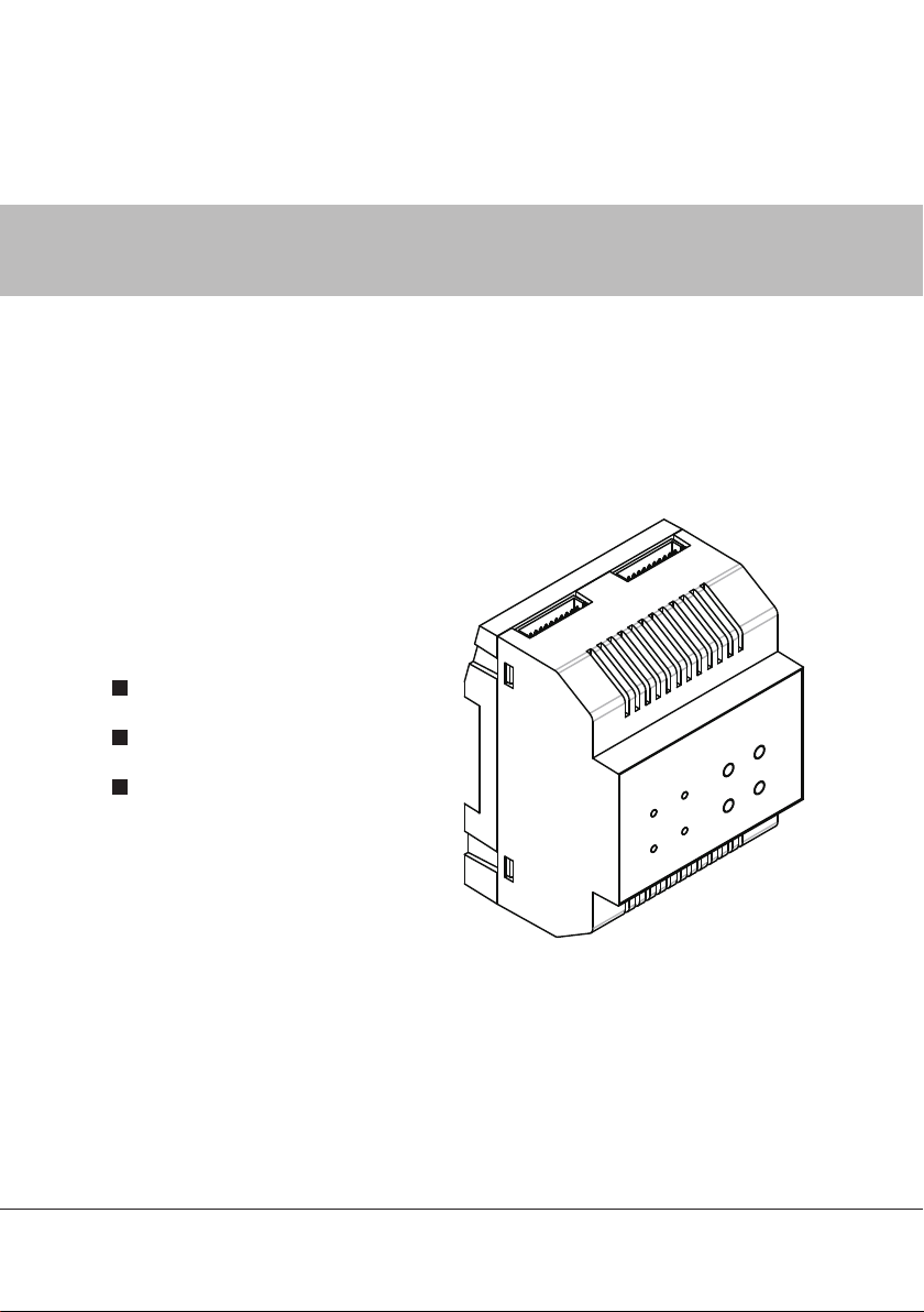
Public memory module
Staircase light controller
Extra cameras extended
User Instruction
DT-ENG-SC6M-V1 P230509
Page 2
Introduction
The SC6M module is designed to DT system for the purpose of public memory
sharing,staircase light control,and extra cameras extended. Note that the SC6M
unit is just for the monitors that support the function only, it must use together
with PC6 to support these functions, and one unit system just use one SC6M
only.
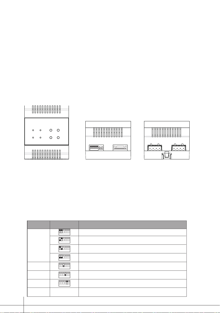
Terminal Description
RS485
1 2 3 4 5 6
ON
SETUP
CN1
SETUP:DIP switches,refer to table 1 for detail information.
RS485:Used to update program for SC6M.
CN1:Input port,connect to PC6.
VD:Output port,connect to DVR.
CAM1:Output port,connect to DT-CAM1(2 wire camera).
CAM2:Output port,connect to DT-CAM2(2 wire camera).
Table1
Bit
DIP1~DIP2
DIP3
DIP4
DIP5
DIP6
Bit State Description
1 2 3 4 5 6
ON
1 2 3 4 5 6
ON
1 2 3 4 5 6
ON
1 2 3 4 5 6
ON
1 2 3 4 5 6
ON
1 2 3 4 5 6
ON
1 2 3 4 5 6
ON
Reserve Reserve
Default setting,ID=0(00),if the system have not any camera controller(SC6),set to 0.
ID=1(10),set to the first camera controller.(SC6)
ID=2(01),set to the second camera controller(SC6).
ID=3(11),set to the third camera controller(SC6).
OFF is default,if the system connect camera1,it should set to ON to activate the camera1
function.
OFF is default,if the system connect camera2,it should set to ON to activate the camera2
function.
OFF is default,if the system connect light,it should set to ON to activate the light function.
CAM1 CAM2
VD
-1-
Page 3
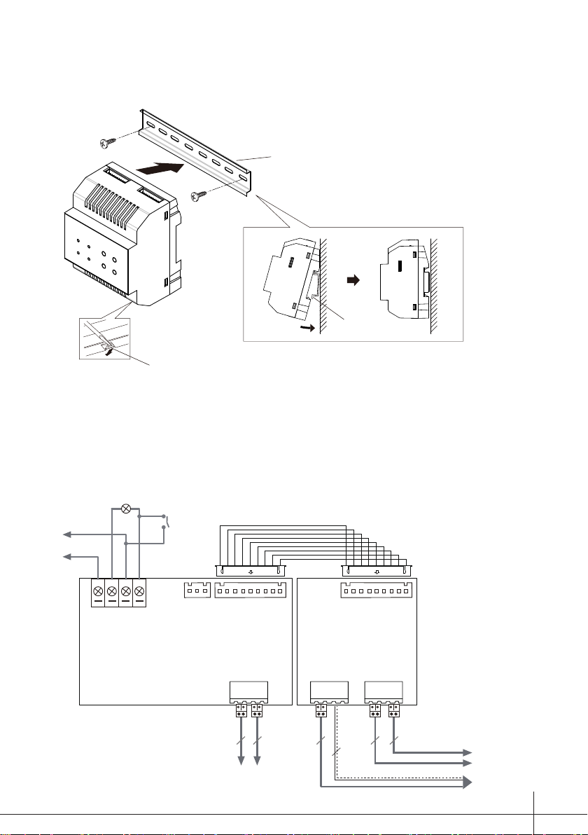
Mounting
Mounting Buckle
Wiring Diagram
Din rail
Step1: Mount the din rail to the
wall with screws ;
Step2: Pull down the mounting
buckle,then hang the unit on
din rail.
Din rail
AC~
connect to light
N N L SW
switch
CN2
1 2 3
CN1
PC6 SC6M
BUS(DS)
BUS(IM)
to monitor
or DBC4S
2
2 2
to door station
2
2
co-ax
to DT-CAM2
to DT-CAM1
to DVR
-2-
Page 4

Note:
1.the SC6M must connect together with PC6 to achieve these functions.
2. one unit system just need one SC6M only.
3. if the system connect SC6M, the picture memory function and calendar will
be activated immediately.
4. if the switch is open, the light will be always on. if the switch is close, the light
is controlled by the monitor.
Picture Memory
• The monitor of the system must support picture memory function.
• Max.800 pictures is supported in SC6M.
• The monitor support both auto record and manual record.
• The recorded pictures can not be deleted on monitor, When the built-in
memory is full,the oldest picture will be deleted to make room for new record .
• The recorded pictures can be played on monitor directly when the system
is not in busy. If the system receives calls, the playback will be interrupted
immediately.
• For the apartment system,each unit can only preview the recorded pictures of
their own user code.
Conguration
-3-
LED BUTTON
RUN
MEM CAM
LIGHT
PROG TURNON
PLAY SWITCH
Page 5

1.When SC6M working in normal, the status of LED and button operation
are as follows:
LED Indicator Description
RUN Always on
LIGHT Light on when the system connect light and it is turned on
MEMORY
CAMERA
BUTTON Description
PROG Press to enter program mode
TURN ON Press to turn on the light
PLAY
SWITCH
- Light on when the recorded pictures is playing
- Light on rst,then light off in 1s when recording pictures
- Light on when camera1 is working
- Blink slowly when camera2 is working
When the monitor is in monitoring, press to playback the
recorded pictures in sequence, press again to play in
forword.
- When the montior is monitoring the view of door station,
press to switch to camera1, press again to switch to
camera2, then switch between camera1 and camera2 in
cycle.
- When the monitor is monitoring the view of camera1,
press to switch to camera2, then switch between camera1
and camera2 in cycle.
2.When SC6M working in program mode, the status of LED and button
operation are as follows:
How to enter program mode: when SC6M working in normal, press PROG
button to enter program mode. If have not any operation in ?? seconds, the
program mode will be quit automatically.
-4-
Page 6

LED Indicator Description
RUN Blink
LIGHT Light on when setting the time for light
MEMORY Light on when formating the SC6M memory
CAMERA Light on when restore to default
BUTTON Description
PROG
TURN ON
PLAY
SWITCH
Press to quit program mode
Press to set the time for light
In program mode,press TURN ON button, the LIGHT
indicator will blink, timing is starting, press the TURN ON
button again to conrm the time of light on.
Press to format the SC6M memory
In program mode,press PLAY button, the MEMORY
indicator will blink, formatting is starting, press the PLAY
button again to conrm the operation.
Press to restore to default
In program mode,press SWITCH button, the CAMERA
indicator will blink, restore to default is starting, press the
SWITCH button again to conrm the operation.
Specication
Power Supply: DC24V(supply by PC6)
Power Consumption: standby:10mA;working:70mA
Working Temperature: -50C ~+450C
Dimension: 90(H)X72(W)X60(D)mm
Warning
- The unit can only be used in DT 2 wire products supplied by our company.
- Don’t connect the unit with any non-specied power source. Fire or electric
shock could result.
- Don’t dismantle or alter the unit. Fire or electric shock could result.
- The unit must be installed and wired by a qualied technician.
- Keep the unit away from water or any other liquid. Fire or electric shock could
result.
-5-
Page 7

Page 8

The design and specications can be changed without notice to the user. Right to
interpret and copyright of this manual are preserved.
DT-ENG-SC6M-V1 P230509
 Loading...