

Page 1
V50
VOLVO
2004
WEB EDITION
Page 2
1
Introduction
Dear Volvo owner
We hope you will enjoy many years of driving pleasure in your Volvo. The car has been designed for the safety and comfort of you and your
passengers. Volvo is one of the safest cars in the world. Your Volvo has also been designed to satisfy all current safety and environmental
requirements. In order to increase your enjoyment of the car, we recommend that you familiarise yourself with the equipment, instructions and
maintenance information contained in this owner's manual.
Thank you for choosing Volvo!
Page 3
2
Introduction
Owner's manual
A good way of getting to know your new car
is to read the owner's manual, ideally before
your first journey. This will give you the
opportunity to familiarise yourself with new
functions, to see how best to handle the car
in different situations, and to make the best
use of all the car's features. Please pay
attention to the safety instructions contained
in the manual:
The equipment described in the owner's
manual is not present in all models. In
addition to standard equipment, this manual
also describes options (factory fitted
equipment) and certain accessories (extra
equipment).
WARNING!
Warning texts indicate where there is a
risk of personal injury in the event of the
instructions not being followed.
IMPORTANT!
Caution texts indicate a risk of damage to
the car in the event of the instructions not
being followed.
NOTE! Volvo cars are differently equipped
depending on the requirements of the
different markets and the national or local
legal requirements and regulations.
The specifications, design features and
illustrations in this Owner’s Manual are not
binding. We reserve the right to make
modifications without prior notice.
© Volvo Car Corporation
Page 4
3
Introduction
Volvo Cars’ Environmental
philosophy
Environmental care, safety and quality are the
three core values which influence all
operations of the Volvo Car Corporation.
Volvo cars comply with strict international
environmental standards and are
manufactured in plants, which are among the
cleanest and most resource-efficient in the
world. Most units within Volvo Car
Corporation are certified to the environmental
standards ISO 14001 or EMAS, which leads
to continuous improvements within the area
of the environment. Volvo Cars is the first car
manufacturer to have a third-party certified
environmental declaration where the
customer can compare the environmental
effects of different models and engines. Read
more at:
www.epd.volvocars.se
Clean inside and out
Your Volvo is built to be "Clean inside and
out", a concept which means you benefit in
two ways - from a clean cabin and a highly
efficient exhaust purification system. Your car
saves fuel and releases minimal quantities of
harmful substances. It also ensures that you
and your passengers do not inhale emissions
from other cars by cleaning the air that comes
into the passenger compartment. A
sophisticated air cleaning system ensures
that the air in the passenger compartment is
cleaner than the air outside. The interior is
free of allergenic substances and there is a
special coating, Premair®
1
, on the radiator
which converts dangerous ground level
ozone to pure oxygen.
1
Applies to cars with five cylinder engines.
Volvo's workshops and the
environment
Regular maintenance at a Volvo workshop
creates the conditions for low fuel
consumption and thus contributes to a
cleaner environment. The personnel have the
knowledge and tools to guarantee the best
possible environmental care.
Page 5

4
Introduction
Save the environment
We believe that our customers share our
concerns about the environment. You can
help save the environment by purchasing
environmentally optimised car care products
and by servicing and maintaining the car
according to the instructions in the owner’s
manual.
Below are a few tips on how to save the
environment:
• Always ensure that the tyres are at the
correct pressure. Too low tyre pressure
results in increased fuel consumption.
• The roof rack and ski-boxes have greater
air resistance and raise fuel
consumption considerably. Remove
them directly after use.
• Remove unnecessary items from the
car. The greater the load, the higher the
fuel consumption.
• Always use the engine block heater
before a cold start, if the car is equipped
with one. This will reduce fuel
consumption and emissions.
• Drive gently. Avoid unnecessary quick
acceleration and heavy braking.
• Drive in the highest gear possible. Low
engine rpm gives lower consumption.
• Relax the accelerator pedal on downhill
slopes.
• Use engine braking. Release the
accelerator and change down.
• Avoid idling. Switch off the engine when
queuing in traffic.
• Remember to dispose of hazardous
waste, e.g. batteries and oil, in an
environmentally favourable manner. Seek
advice from your Volvo workshop if
unsure about disposal.
• Maintain the ignition and fuel systems,
which directly reduce exhaust
emissions.
By following this advice fuel consumption can
be reduced without affecting either the
journey time or the enjoyment of driving. You
preserve the car, money and the planet's
resources.
Page 6

5
Table of Contents
Instrument overview 7
Safety 13
Instruments and controls 33
Climate control 59
Interior 71
Locks and alarm 83
Starting and driving 93
Wheels and tyres 119
Car care 133
Maintenance and service 139
Infotainment 163
Specifications 191
Page 7

6
Table of Contents
Page 8

7
Instrument overview
Instrument overview
Overview left-hand drive cars 8
Overview right-hand drive cars 10
Driver’s door control panel 12
Page 9
8
Instrument overview
Left-hand drive
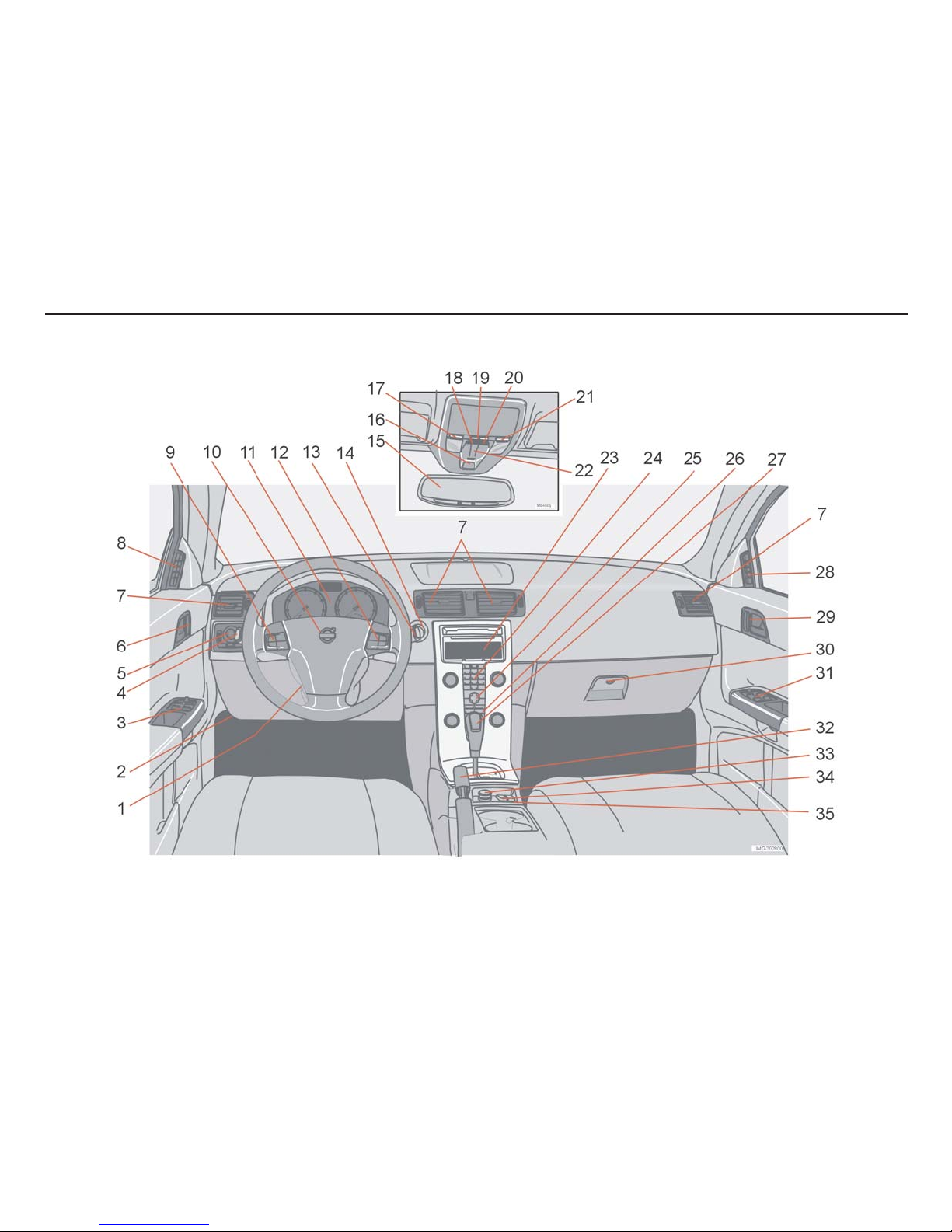
Overview, left-hand drive cars
Page 10

9
Instrument overview
1.
Steering wheel adjustment
2.
Bonnet release
3.
Control panel
4.
Direction indicators, main beam, trip
computer
5.
Lighting, fuel filler flap opener
6.
Door handle, central locking
7.
Air vents in the dashboard
8.
Air vent side window
9.
Cruise control
10.
Horn, airbag
11.
Combined instrument panel
12.
Keypad Infotainment
13.
Windscreen wipers and washers,
headlamp washers
14.
Ignition switch
15.
Rearview mirror, compass
16.
Seat belt reminder
17.
Interior lighting left-hand side
18.
Movement detector, alarm
19.
Interior lighting function switch
20.
Position for accessory switch
21.
Interior lighting right-hand side
22.
Operation, sunroof
23.
Display for climate control and
infotainment
24.
Infotainment
25.
Settings for climate control,
infotainment and personal settings
26.
Climate control
27.
Gear lever
28.
Air vent, side window
29.
Door handle
30.
Glovebox
31.
Control panel
32.
Parking brake
33.
Electric socket/Cigarette lighter
34.
Stability system STC or DSTC
35.
Switch, optional equipment
Page 11
10
Instrument overview
Right-hand drive
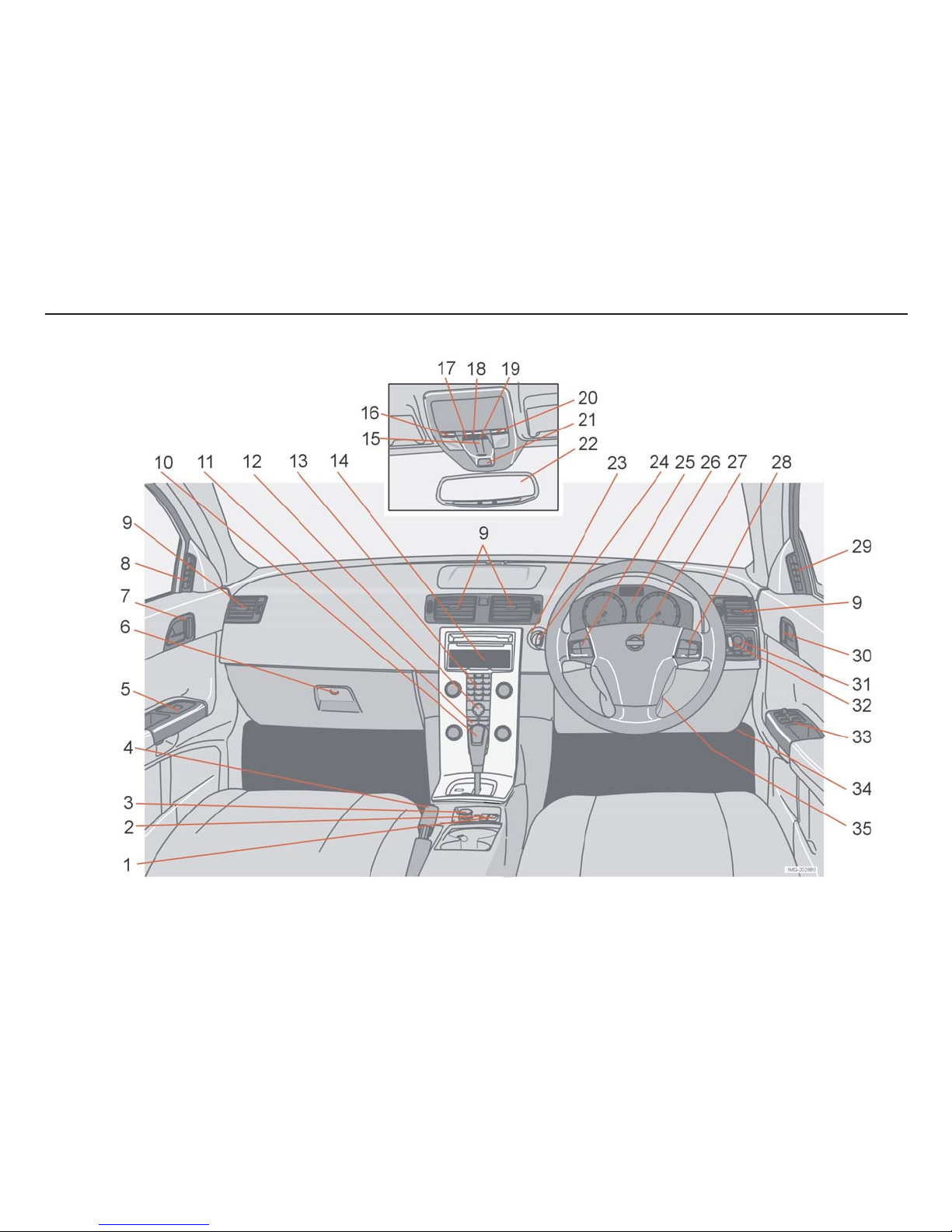
Overview right-hand drive car
Page 12

11
Instrument overview
1.
Switch, post installed accessory
2.
Stability system STC or DSTC
3.
Electric socket
4.
Parking brake
5.
Control panel
6.
Glovebox
7.
Central locking
8.
Air vent, side window
9.
Air vents in the dashboard
10.
Gear lever
11.
Climate control
12.
Settings, climate control and
infotainment
13.
Infotainment
14.
Display, climate control and
infotainment
15.
Operation, sunroof
16.
Interior lighting, left-hand side
17.
Central locking
18.
Interior lighting, switch
19.
Switch, post installed accessory
20.
Interior lighting, right-hand side
21.
Seat belt reminder
22.
Mirrors, compass
23.
Ignition switch
24.
Direction indicators, main beam, trip
computer
25.
Cruise control
26.
Combined instrument panel
27.
Horn, airbag
28.
Infotainment
29.
Air vent, side window
30.
Central locking
31.
Lighting, fuel filler flap opener
32.
Windscreen wipers and washers,
headlamp washers
33.
Control panel
34.
Bonnet release
35.
Steering wheel adjustment
Page 13

12
Instrument overview
Electric child lock (option).
Power windows
Door mirror, left-hand side
Door mirrors, setting
Door mirror, right-hand side
Driver’s door control panel
Page 14

13
Safety
Safety
Seat belts 14
Airbags 17
Side airbags 20
Inflatable curtain 22
WHIPS 23
When are the safety systems activated? 25
Crash mode 26
Inspecting air bags and inflatable curtains 27
Child safety 28
Page 15
14
Safety
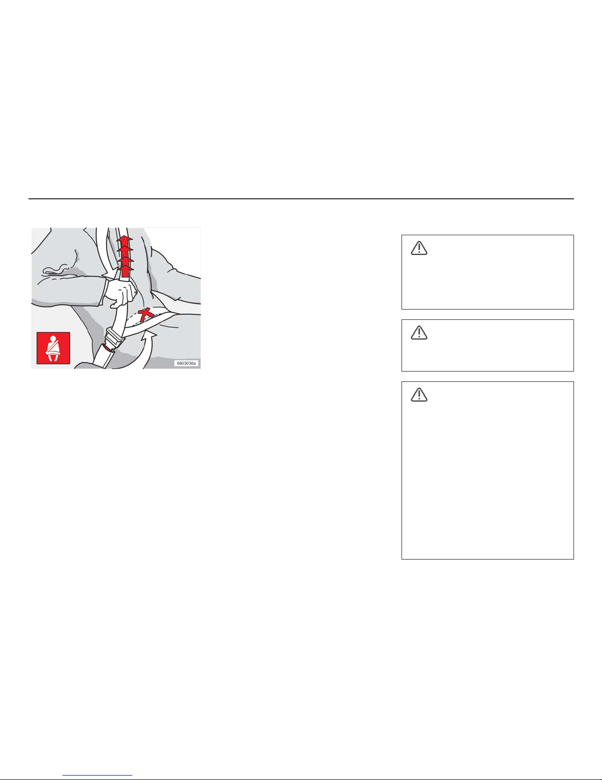
Extending the lap belt. The belt must be
positioned low down.
Always use a seat belt
Braking could have serious consequences if
the seat belt is not used. Ensure that all
passengers are wearing their seatbelts.
Otherwise, rear seat passengers may be
thrown against the front seat backrests in a
collision.
Putting on the seat belt:
• Pull the belt out slowly and secure it by
inserting the locking tab into the lock. A
loud "click" indicates that the belt is
locked.
Seat belts
Release the belt:
• Press the red button in the lock and
allow the reel to retract the belt. If the
belt is not completely retracted, feed in
the belt manually to prevent it from
hanging loose.
The belt is restricted and cannot be pulled
out further:
• if it is pulled out too fast
• during braking and acceleration
• if the car leans heavily.
It is important that the belt lies snugly against
the body so it can provide maximum
protection. Do not lean the backrest too far
back. The seat belt is designed to protect in
a normal seating position.
Keep the following in mind:
• do not use clips or anything else that
prevents the belt from fitting correctly
• ensure the belt is not twisted or caught
on anything
• the lap belt must sit low down (not over
the abdomen)
• stretch the lap belt over the lap by
pulling the diagonal shoulder belt as
illustrated.
WARNING!
The seat belt and airbag operate
together. If the seatbelt is not used or is
incorrectly used airbag operation can be
affected in the event of a collision.
WARNING!
Each belt is intended for one person
only.
WARNING!
• If the belt has been exposed to a major
load, in a collision for example, the entire
belt must be replaced. This includes
reels, mountings, screws and locks.
Some of the protective characteristics of
the belt may have been lost, even if the
belt does not appear to be damaged.
Replace the seat belt if it is worn or
damaged. The new seat belt must be
approved and intended for installation in
the same position as the replaced belt.
• Never modify or repair the seatbelts
yourself. Contact a Volvo workshop.
Page 16
15
Safety
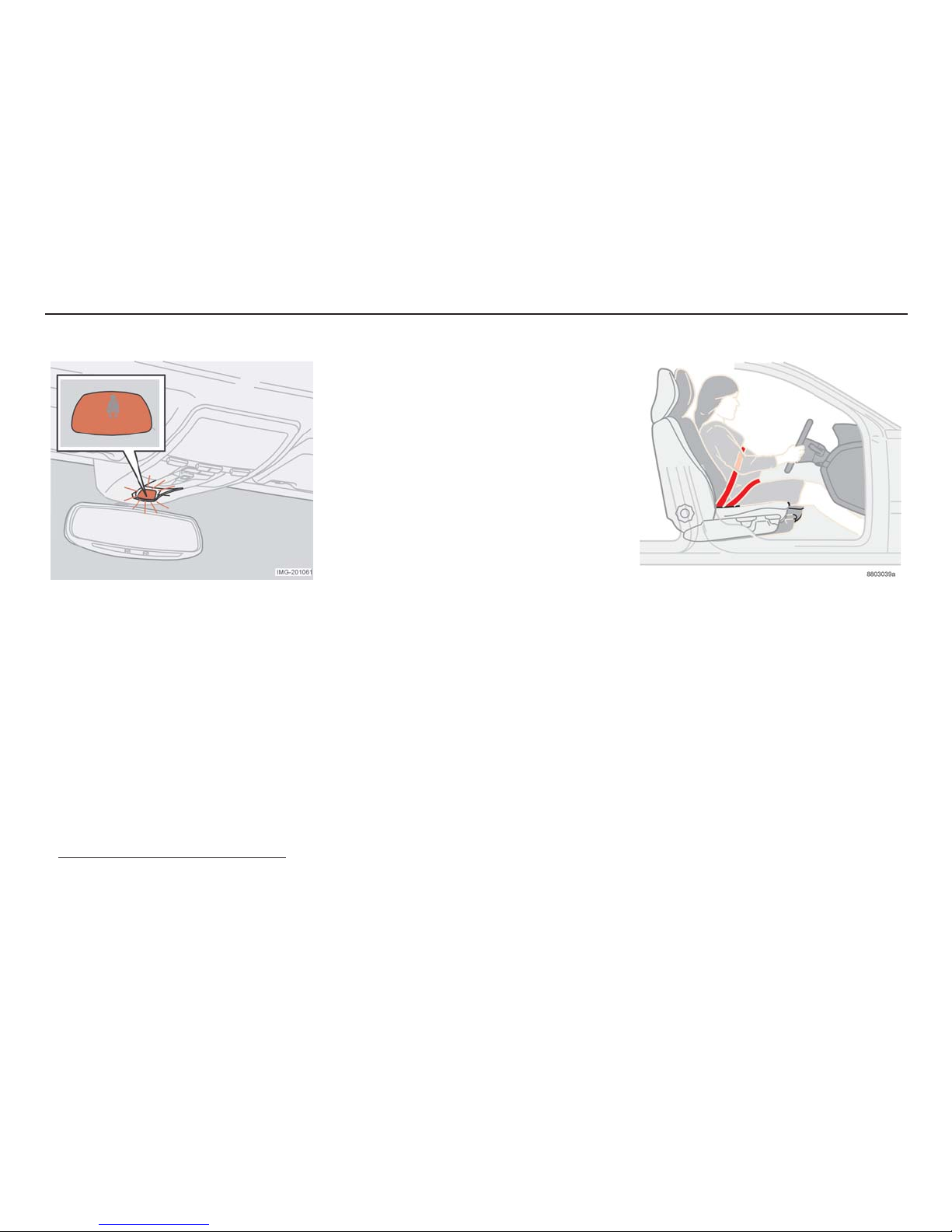
Seat belt reminder
1
A symbol lights up in the roof console (above
the rearview mirror) as a reminder that the
seat belt is not being worn. A symbol also
lights up on the dashboard. If the car is
stationary, the reminder disappears after
approximately 6 seconds.
Front seat
The symbols remain lit if the driver or front
passenger is not wearing their seat belt. (No
signal is given if a child seat is installed in the
front seat.) In addition to the two lit symbols,
1
The functions may vary slightly depending
on the market
an audible signal is heard that changes
frequency depending on the speed of the car.
Rear seat
The seat belt reminder is activated if a
passenger in the rear seat takes off the seat
belt during a journey. If one of the rear doors
is opened and closed, the system checks for
ten seconds how many of the seat belts are
in use and presents this number in the
information display, e.g. 2-3 REAR BELTS IN
USE. No light or audible reminder is given.
This only takes place when a seat belt is
removed.
The seat belt reminder for the rear seat can
be switched off:
• Hold in the READ-button on the left-
hand steering wheel stalk until a
message verifies that the function has
been switched off.
Pregnant women
Pregnant women must take particular care
when securing the seat belt. Position the belt
so that it does not exert unnecessary
pressure on the womb. The lap belt of the
three-point seat belt should be low.
Page 17
16
Safety
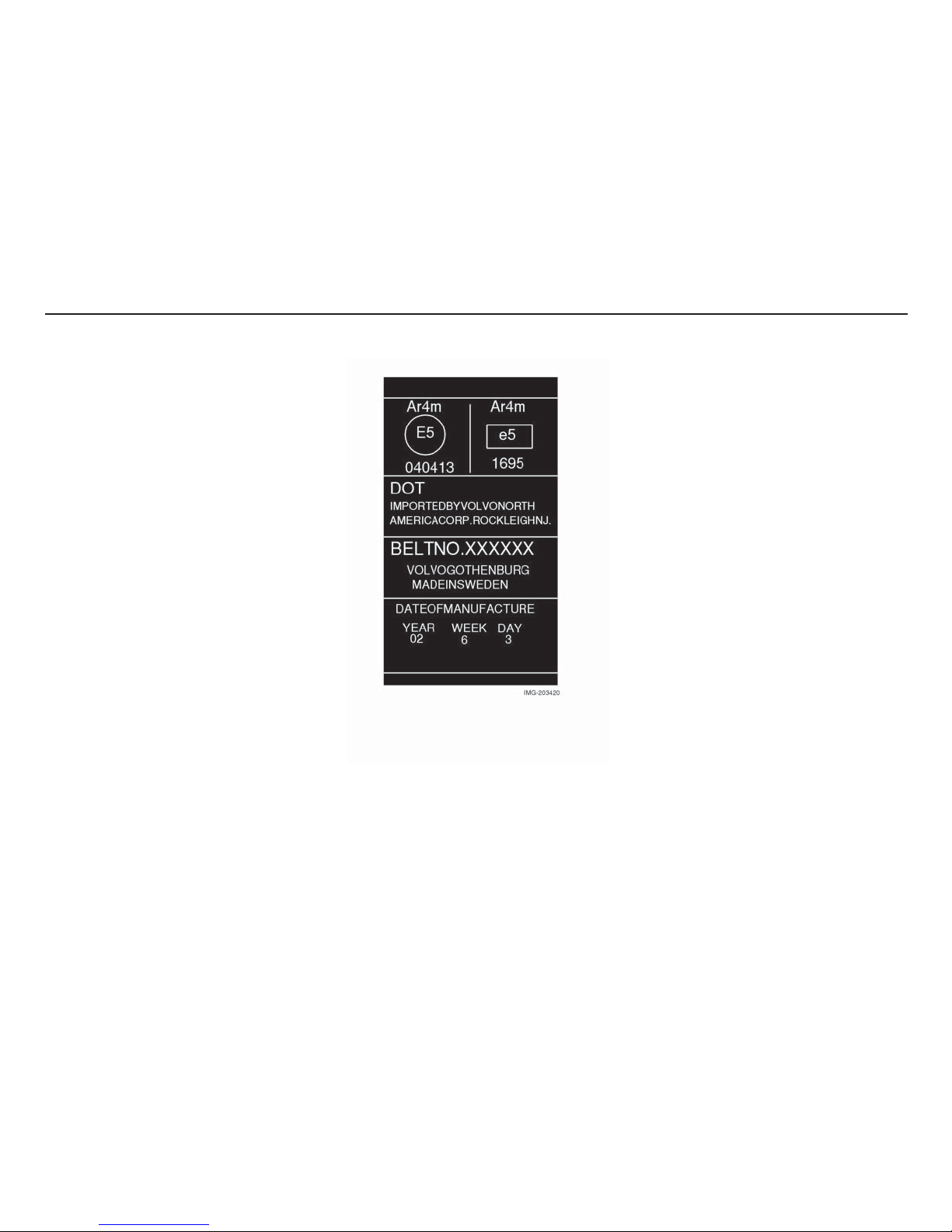
Seat belt tensioner
All the seat belts (with the exception of the
rear centre position) have seat belt
tensioners. This is a mechanism which, at the
moment of impact, tensions the seatbelt
around the body. The belt therefore restrains
the passenger more quickly.
Marking on seat belts with seat belt
tensioners
Page 18
17
Safety
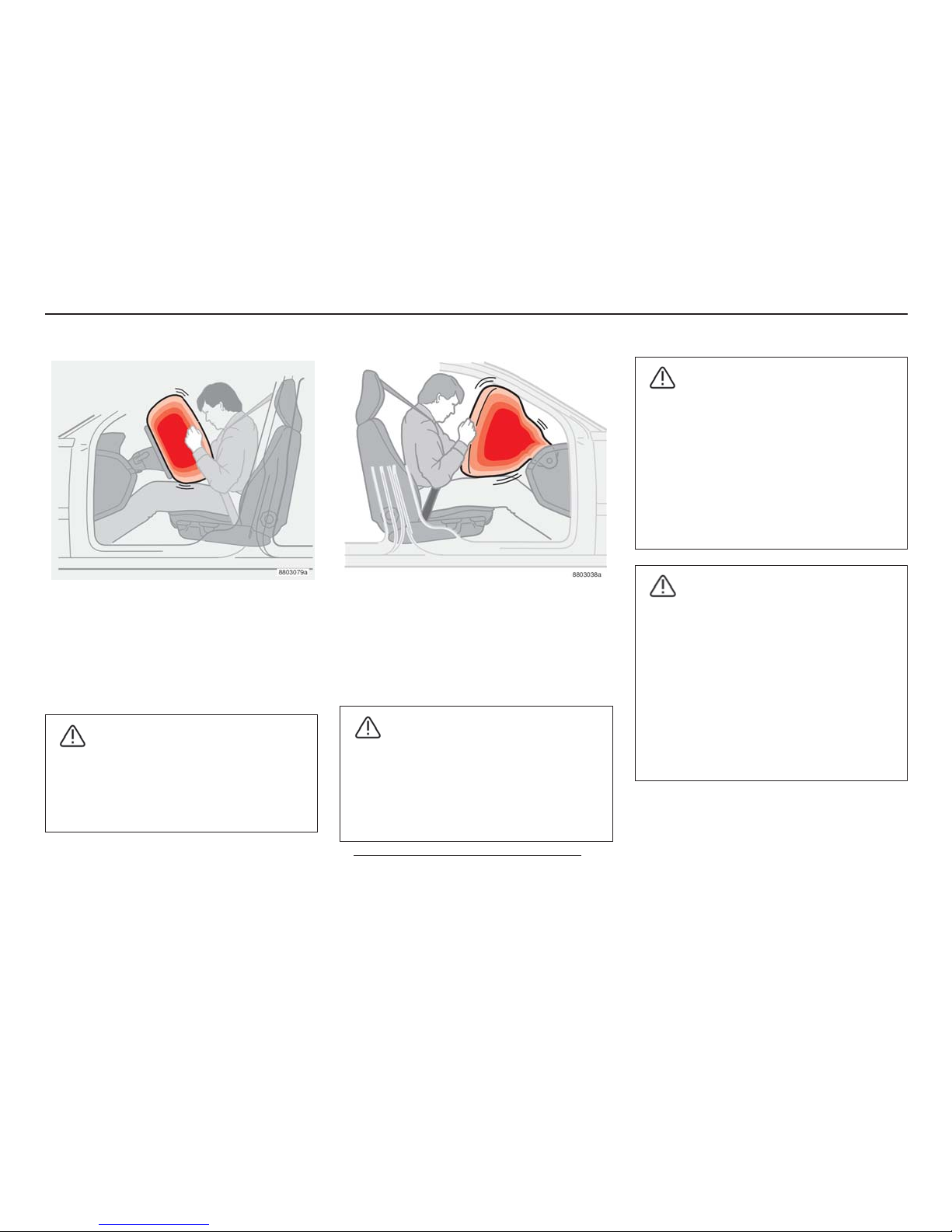
Driver’s airbag
In addition to the seat belts, the car has an
airbag (SRS - Supplemental Restraint
System) in the steering wheel. The airbag is
folded into the centre of the steering wheel.
The wheel is marked SRS AIRBAG.
WARNING!
The seat belt and airbag operate
together. If the seatbelt is not used or is
incorrectly used airbag operation can be
affected in the event of a collision.
Airbags
Front passenger airbag
1
The airbag on the passenger side is
folded up in a compartment above the
glove box. The panel is marked SRS
AIRBAG.
1
Not all cars have passenger side air bags. It
can be optionally excluded at purchase.
WARNING!
To minimise the risk of injury if the airbag
deploys, passengers must sit as upright
as possible with their feet on the floor
and backs against the backrest. Seat
belts should be secured.
WARNING!
• No objects or accessories may be
positioned or stuck on, or near, the
SRS AIRBAG panel (above the glove
box) or in the area affected by the
airbag.
• Never interfere with SRS
components in the steering wheel or
the panel above the glove box.
WARNING!
• Never place a child seat or booster
cushion on the passenger seat if the
car has an airbag on the passenger
side.
• Never allow a child to stand or sit in
front of the front passenger seat.
• No one shorter than 140 cm (4 ft 7)
should sit in the front passenger
seat.
Page 19
18
Safety
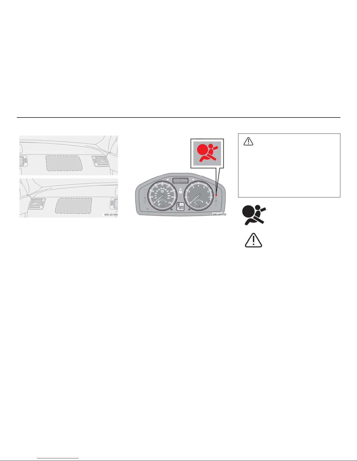
Location of the airbag on the passenger
side, left-hand drive/right-hand drive cars
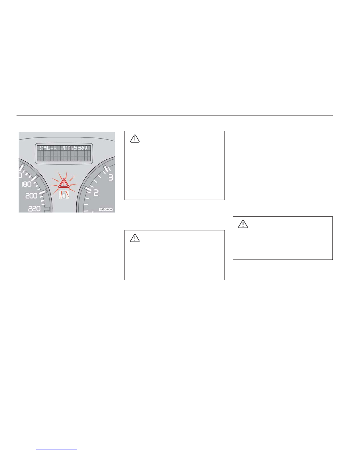
Warning symbol in the centre of
the dashboard
The SRS system is continuously monitored
by the car's electronic system. The warning
symbol in the combined instrument panel
lights when the ignition key is turned to
positions I, II or III. The symbol goes out
after approximately six seconds if the SRS
system is fault-free.
As well as the symbol, a
message appears in the
information display. If the
warning symbol is defective,
the warning triangle is lit and
the message SRS AIRBAG
SERVICE URGENT appears
in the display.
WARNING!
If the SRS warning symbol remains lit or
lights while driving, it means that the
SRS system is not functioning fully. The
symbol can also indicate a fault in the
seat belt buckle, the SIPS or the IC
system. Contact a Volvo workshop
immediately.
Page 20
19
Safety
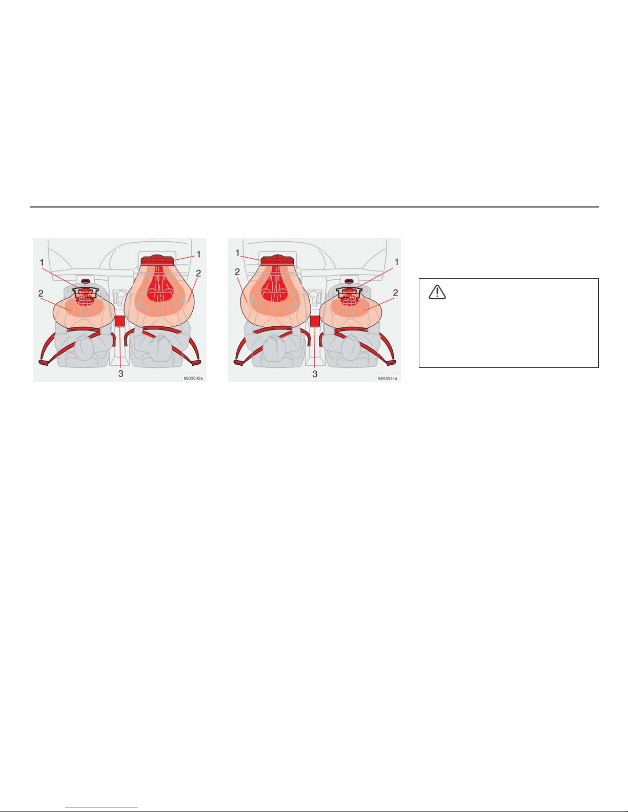
SRS system, left-hand drive
SRS System
The system consists of a gas generator (1)
surrounded by the inflatable airbag (2). Upon
a sufficiently violent collision, sensors (3)
react, activating the gas generator igniters
and the airbag inflates as it heats up. To
cushion the impact, the airbag deflates when
compressed. When this occurs, smoke also
escapes into the car. This is completely
normal. The entire process, including inflation
and deflation of the airbag, occurs in tenths of
a second.
SRS system, right-hand drive.
NOTE! The sensors (3) react differently
depending on the severity of the collision and
whether the driver or passenger side seat
belts are in use. Crash situations may occur
where only one airbag is deployed. In a
collision, the SRS system sensors detect the
deceleration caused by the collision. The
system determines if the collision is of the
character and nature requiring one or more
airbags to deploy to protect the occupants.
NOTE! In certain collisions, only one (or no)
airbag is activated.
Dual-stage airbags
(Volvo Dual-Stage Airbag)
If a collision is mild but sufficiently violent that
there is a risk of personal injury, the airbags
are partially inflated. If the collision is more
severe, the airbags are inflated fully.
WARNING!
Any interference in the SRS system
could cause malfunction and serious
injury.
Repair work may only be performed by a
Volvo workshop.
Page 21
20
Safety
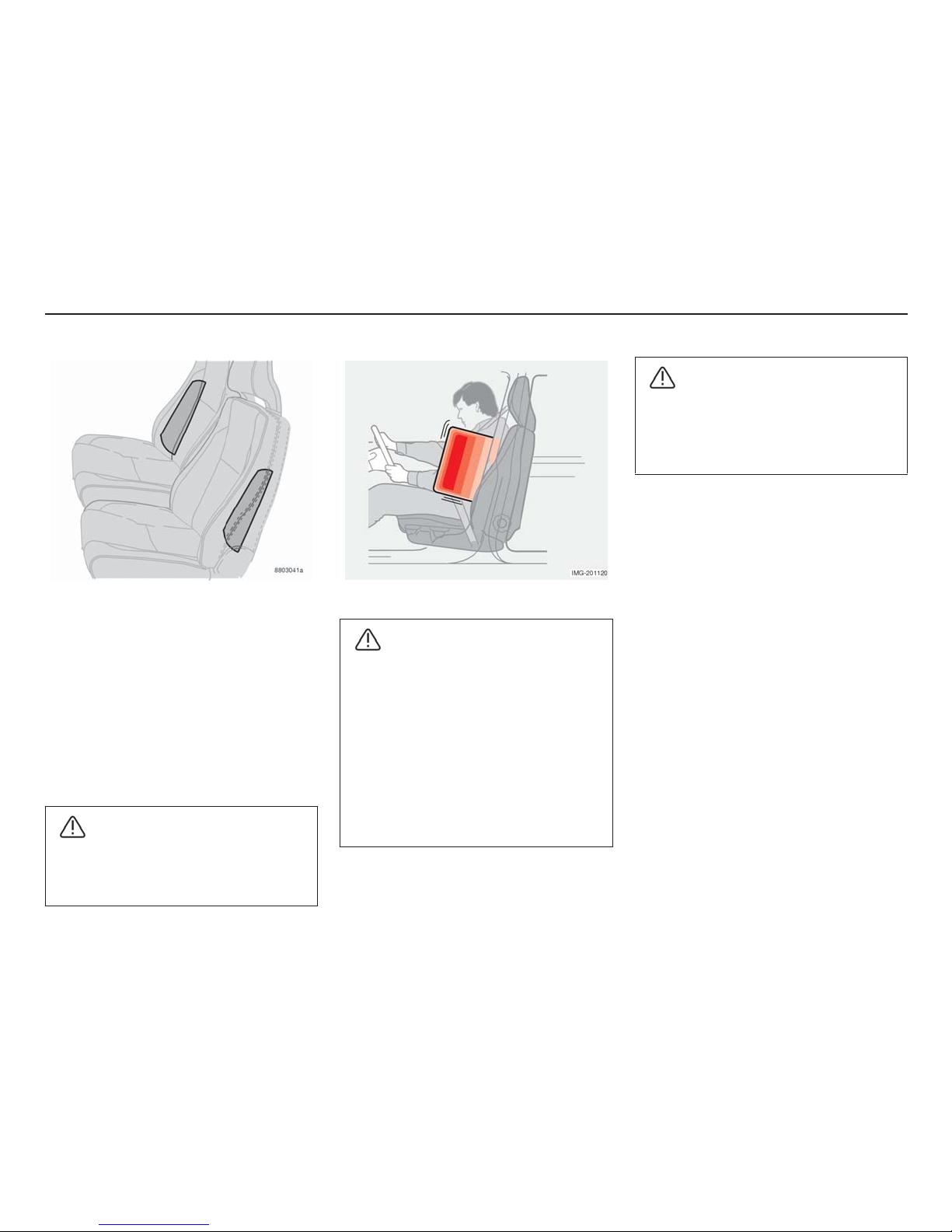
Side airbags - SIPS bag
A large proportion of the collision force is
distributed by SIPS to the members, posts,
floor, roof and other parts of the car body.
The side airbags protect the chest and are an
important part of SIPS. The SIPS airbag
system consists of two main components:
Side airbags and sensors. The side airbags
are installed in the frames of the front seat
backrests and the sensors are located on the
insides of the centre and rear pillars.
WARNING!
The side airbags supplement the
existing SIPS system. Always use seat
belts.
Side airbags
WARNING!
• Any interference with the SIPS (side
impact protection system) airbag
system could cause malfunction and
serious injury. Contact a Volvo
Workshop instead.
• No objects or accessories may be
placed between the outer side of the
seat and the door panel because this
area may be affected by the side
airbag.
Child seats and side airbags
A child seat/booster cushion can be placed
in the front seat as long as the car is not
equipped with an airbag on the passenger
side.
WARNING!
Only use Volvo upholstery or upholstery
approved by Volvo. Other upholstery
may impede the function of the side
airbags.
Page 22
21
Safety
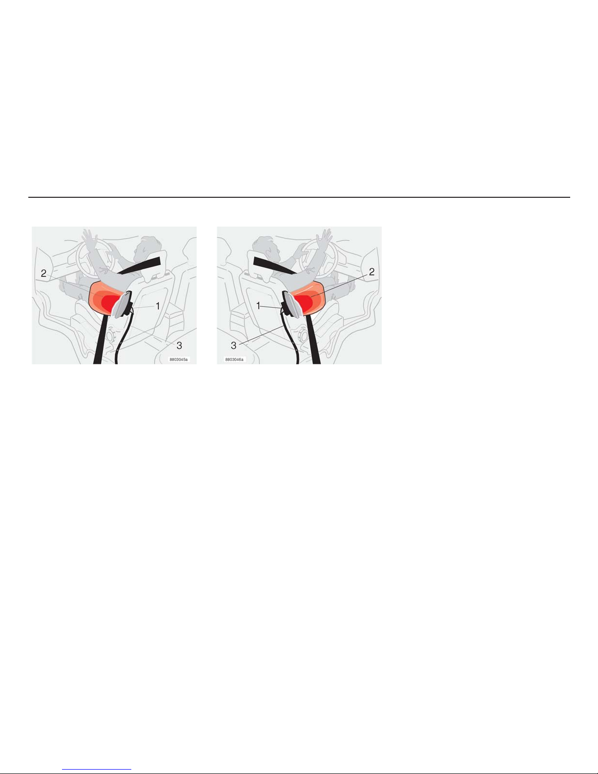
Left-hand drive
Side impact protection system
(SIPS)
The SIPS airbag consists of a gas generator
(1), side airbag(2) and sensors (3). When a
sufficiently violent collision occurs, the
sensors react and activate the gas generator
which inflates the side airbag. The airbag
inflates between the occupant and the door
panel, cushioning the impact at the moment
of collision, and then deflates. Normally, only
the side airbag on the side of the collision
inflates.
Right-hand drive
Page 23
22
Safety
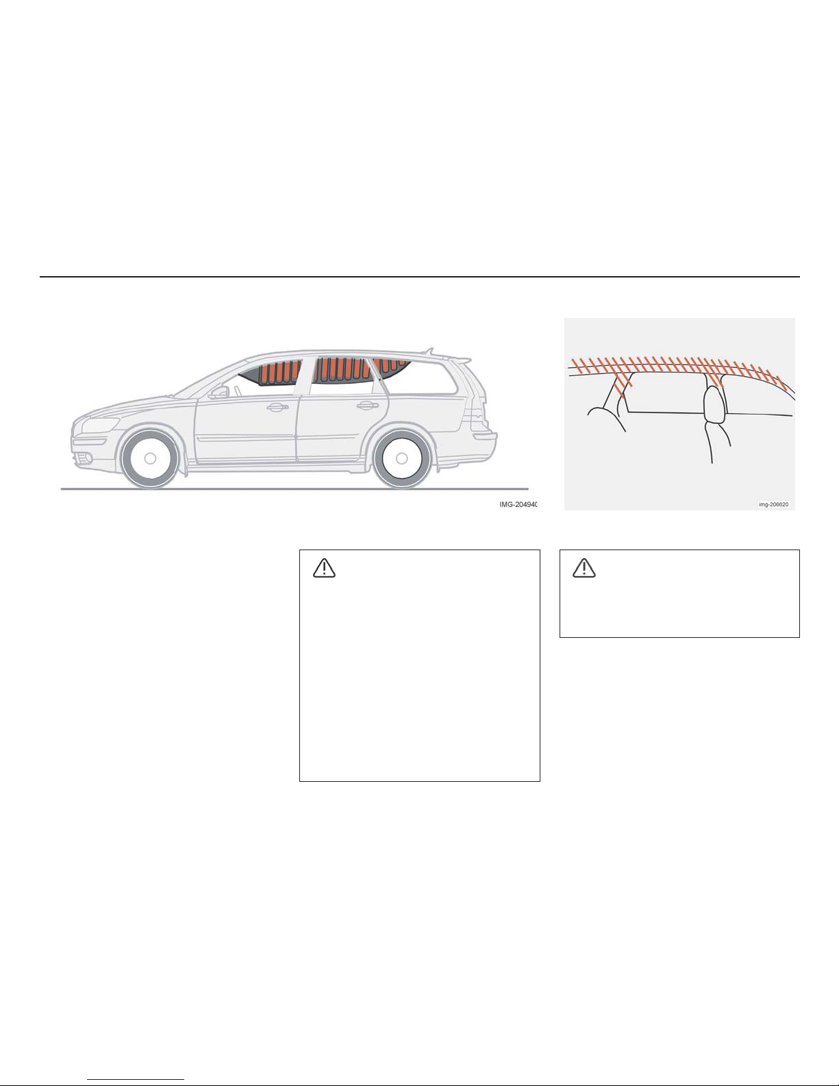
Properties
The inflatable curtain supplements the
existing SIPS system. The inflatable curtain is
concealed in the headlining along both sides
of the car. It protects both the front and rear
seat. If the car is hit from the side, the
inflatable curtain deploys within a few
thousandths of a second. It is then inflated for
approximately three seconds to provide
maximum protection in the event of a
complicated, severe collision. The inflatable
curtain is activated by the SIPS system
collision sensors if the car is hit from the side.
The inflatable curtain is filled with gas when
activated. The inflatable curtain helps to
prevent the driver's and passengers heads
from hitting the inside of the car in the event
of a collision.
Inflatable curtain
WARNING!
• Never hang or secure anything from
the handles in the roof. The hook is
only intended for light outer garments
(not for hard objects such as
umbrellas).
• Do not screw to, or mount anything
on the headlining, door pillars or side
panels. The intended protection may
then be compromised. Only Volvo
Genuine parts that are approved for
placement in these areas should be
used.
WARNING!
The inflatable curtain is a supplement to
the seat belt.
Always use a seat belt.
Page 24
23
Safety
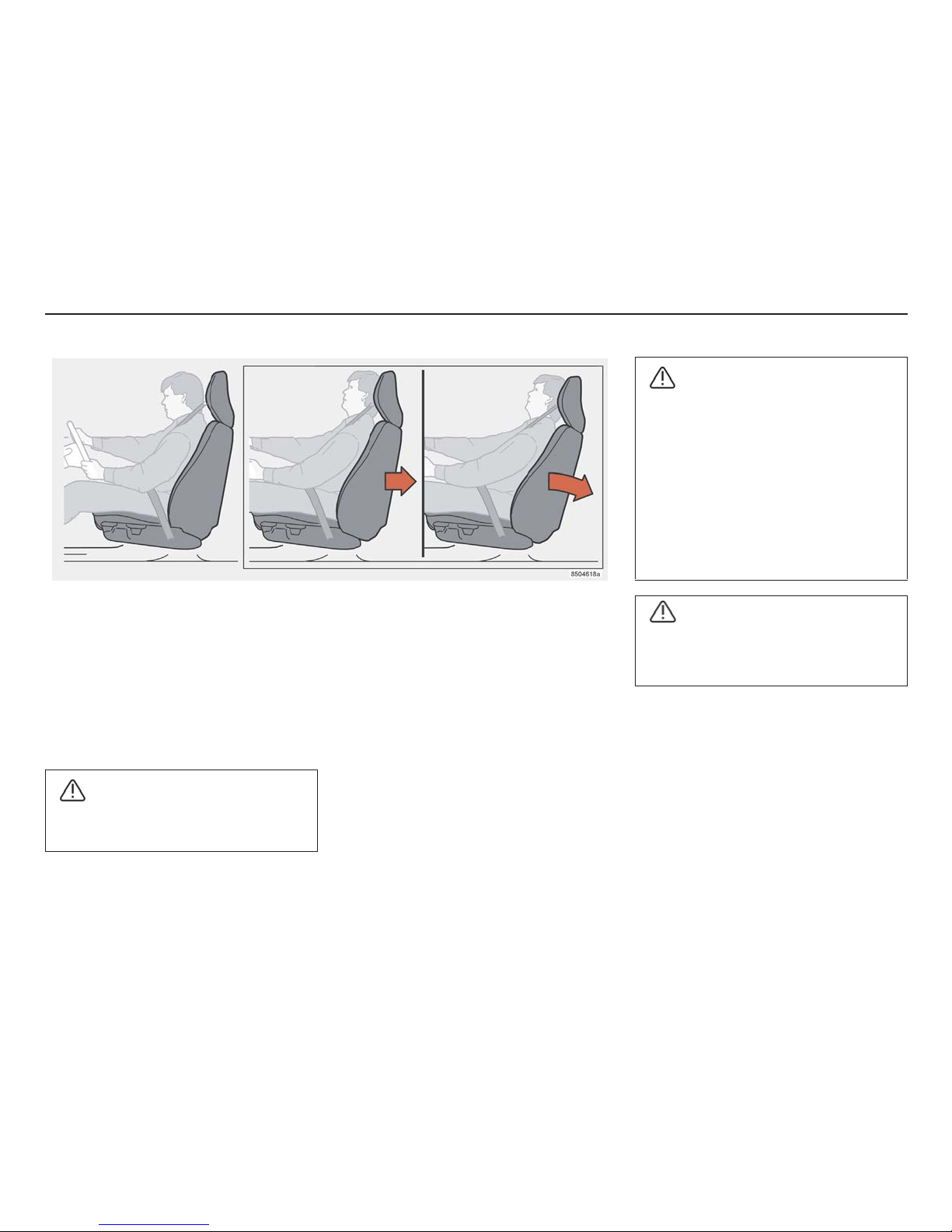
Protection against whiplash
injuries - WHIPS
The WHIPS system ( Whiplash Protection
System) consists of energy absorbing
backrests and specially developed head
restraints in both front seats. The system is
activated upon a collision from behind, based
on the collision angle, speed and nature of
the colliding vehicle.
WARNING!
The WHIPS system is a supplement to
the seat belt. Always use seat belts.
WHIPS
The seat's properties
When the WHIPS system is activated the
front seat backrests fall backwards to alter
the position of the driver's and passengers in
the front. This diminishes the risk of whiplash
injury.
Correct seating position
For the best possible protection, the driver
and front seat passenger should sit in the
centre of the seat with as little distance as
possible between the head restraints and
head.
WHIPS system and child seats
The WHIPS system does not negatively
affect the protective properties of the car with
regard to child seats.
WARNING!
• If the seat has been exposed to a heavy
load strain, such as in a rear-end
collision, the WHIPS system must be
inspected by a Volvo workshop.
• Even if the seat seems undamaged,
some of the protective properties of
the WHIPS system may have been
lost. Contact a Volvo workshop to
check the system, even after minor
rear end collisions.
WARNING!
Never modify or repair the seat or
WHIPS system yourself. Contact a
Volvo workshop.
Page 25
24
Safety
The following can be used:
• a child seat in the front passenger seat,
provided that the airbag on the
passenger side has been deactivated.
• a rear facing child seat in the rear seat
supported against the backrest of the
front seat.
Do not hinder the function of the
WHIPS system
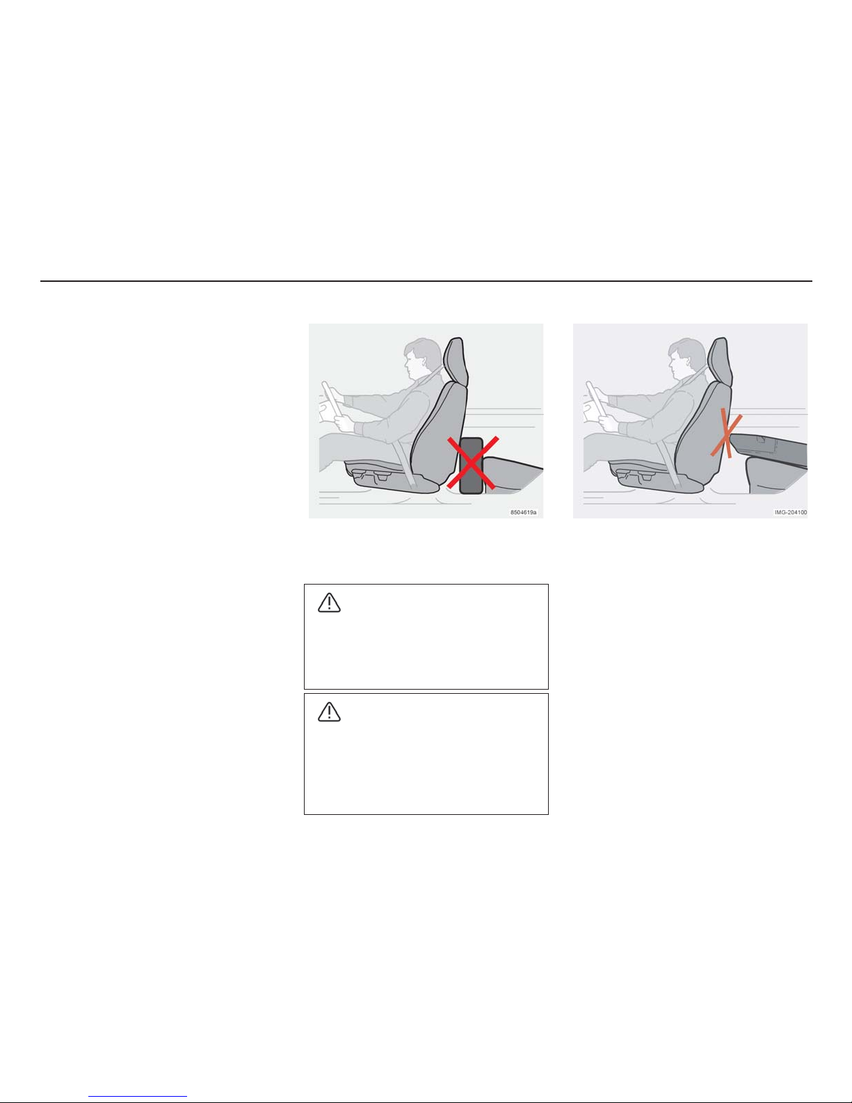
WARNING!
If a rear backrest is folded down, the
corresponding front seat must be moved
forward so that it is not in contact with
the folded backrest.
WARNING!
Do not place a box or similar cargo so
that it is squeezed between the seat
cushion of the rear seat and the backrest
of the front seat. Be sure to never hinder
the function of the WHIPS system.
Page 26
25
Safety
If the airbags have been deployed, we
recommend the following:
• Tow the car to a Volvo workshop. Never
drive with deployed airbags.
• Let a Volvo workshop replace
components in the car's safety system.
• The airbags do not always deploy in the
event of a frontal collision. This means
that the function was not needed at that
moment and the passengers were
protected by the other safety systems of
the car.
NOTE! The SRS, SIPS and IC systems are
only deployed once in a collision.
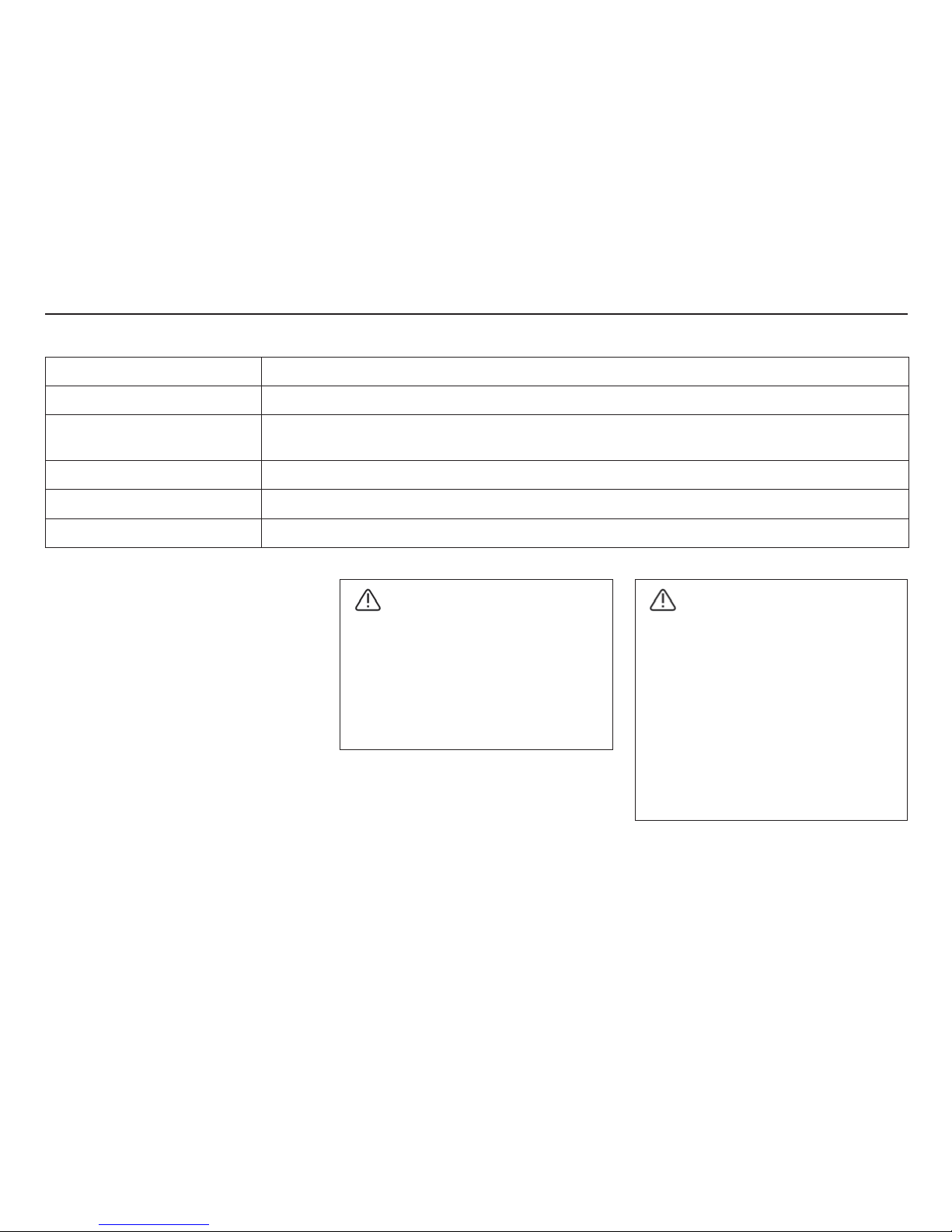
System Triggered
Seat belt tensioner In frontal collisions. The seat belt is tensioned around the body to restrain the passenger more quickly.
Airbags (SRS) In collisions if there is a risk that front seat passengers could be injured by hitting the dashboard or
steering wheel.
Side airbags SIPS In side-on collisions if the car is hit with sufficient force.
Inflatable Curtain (IC) In side-on collisions. The curtain reduces the risk of head injuries.
Whiplash protection (WHIPS) When hit from behind. Reduces the risk of whiplash.
When are the safety systems activated?
WARNING!
The SRS system sensor is located in the
centre console. Disconnect the battery
cables if the floor of the passenger
compartment has been drenched with
water. Do not try to start the car, as the
airbags may deploy. Have the car
recovered to a Volvo workshop.
WARNING!
Never drive with deployed airbags.
This may make the car difficult to steer.
Other safety systems may also be
damaged. Intense exposure to the
smoke and dust released when the air
bags are deployed can cause skin and
eye irritation. In case of problems, wash
with cold water and contact a doctor.
The speed of the deployment and the
airbag fabric may cause friction burns on
the skin.
Page 27
26
Safety
Driving after a collision
If the car has been involved in a collision, the
text CRASH MODE - SEE MANUAL may
appear in the information display. This means
the functionality of the car has been reduced.
CRASH MODE is a safety feature that
comes into effect when the collision could
have damaged an important function in the
car, for example fuel lines, sensors for one of
the safety systems or the brake system.
Crash mode
Attempting to start the car
First check that no fuel has escaped from the
car. There should not be any fuel odour.
If everything appears normal and you have
checked for fuel leakage, you may attempt to
start the car.
• First remove the ignition key, then
reinsert it. The car's electronics will try
to reset themselves to normal mode.
Then try to start the car.
WARNING!
Never try to repair the car yourself or to
reset the electronics after the car has
been in CRASH MODE. This could
result in injury or the car not functioning
as normal. Always allow a Volvo
workshop to handle checking and
restoring the car to normal status after
CRASH MODE has been displayed.
WARNING!
Do not attempt to restart the car under
any circumstances if there is any fuel
odour when the CRASH MODE
message is displayed. Leave the car
immediately.
Moving the car
If the normal mode is displayed after the
CRASH MODE has been reset, the car may
be moved carefully out of its present
dangerous position. Do not move the car
further than necessary.
Recovery
Even if the car appears driveable after it has
been put into CRASH MODE, it should not
be driven or towed. When travelling,
concealed damage can make the car
impossible to manoeuvre.
WARNING!
The car may not be towed once it has be
put in CRASH MODE. It must be
recovered from its present location to a
Volvo workshop.
Page 28
27
Safety
Inspection intervals
The year and month specified on the decal on
the door pillar(s) is the date you should
contact your Volvo Workshop to inspect, and
if necessary, replace the airbags, seat belt
tensioners and inflatable curtains. If you have
any questions about the systems, please
contact a Volvo workshop.
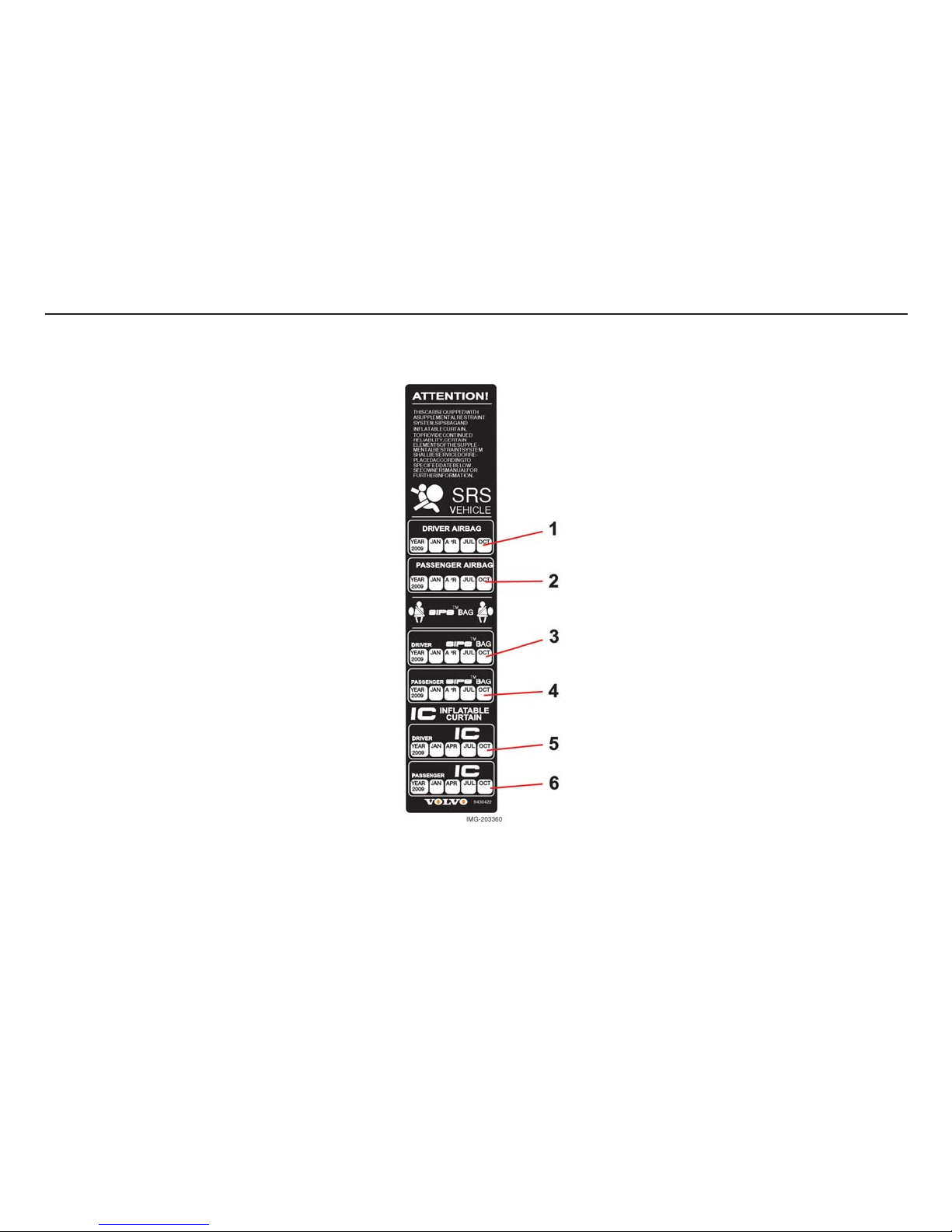
Inspecting air bags and inflatable curtains
This decal is located in the rear left door
opening.
1. Driver’s airbag
2. Front passenger airbag
3. Side airbag on the driver’s side
4. Side airbag on the passenger side
5. Inflatable curtain on the driver’s side
6. Inflatable curtain on the passenger side
Page 29
28
Safety
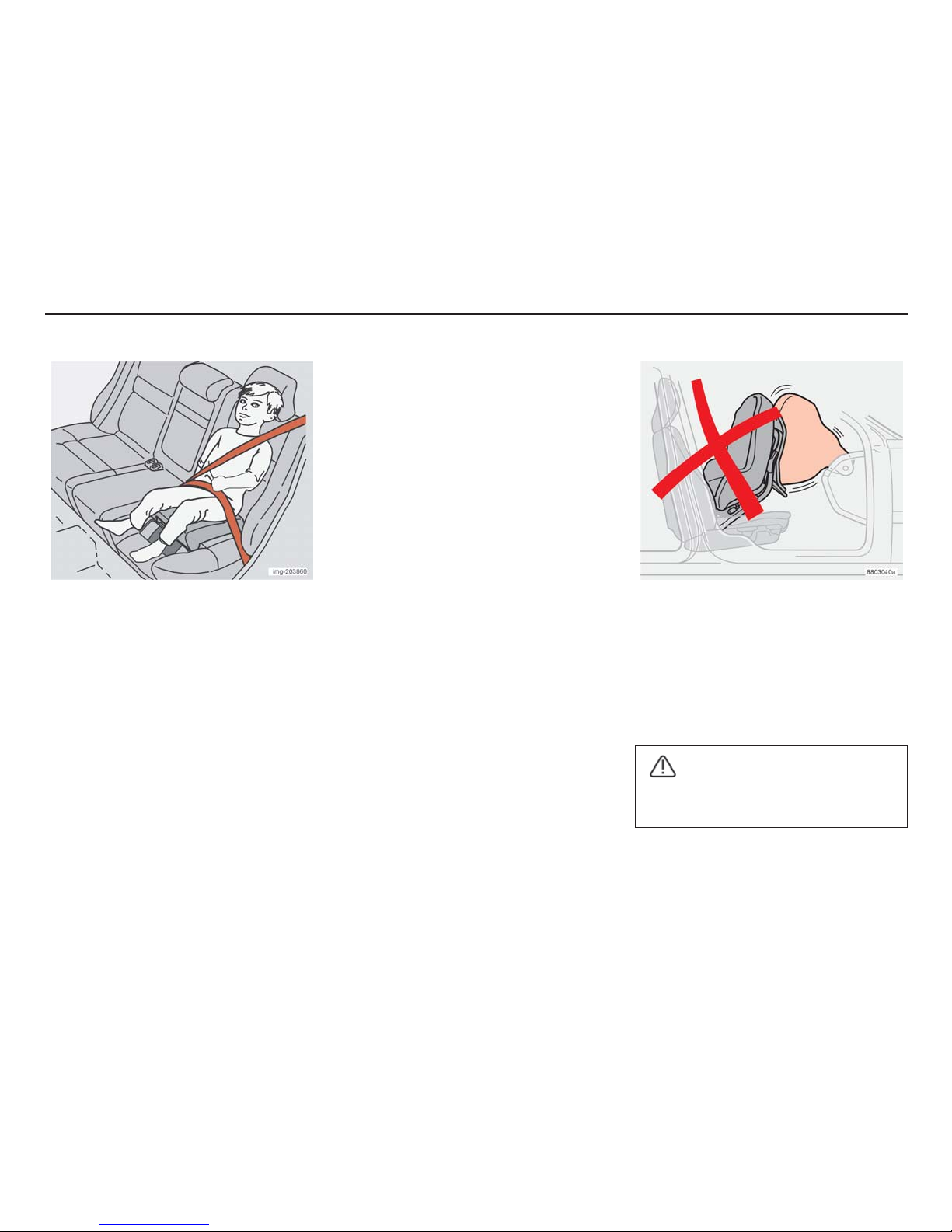
Children should sit comfortably
and safely
The position of the child in the car and the
equipment required is dictated by the weight
and height of the child. The table “Position of
children” page 30 in the car gives the
necessary information.
• Children of all ages and sizes must
always be secured in the car. Never
allow a child to sit on the knee of a
passenger.
Volvo’s own child safety equipment is
designed for your car. The use of Volvo
genuine equipment ensures that the
mounting points and attachments are
correctly positioned and sufficiently strong.
Child safety
NOTE! Regulations regarding where children
may be placed in the car vary from country to
country. Check what laws apply.
Child seats and airbags are not compatible
Child seats and airbags
Always place the child in the rear seat if the
passenger seat airbag is activated. If the
airbag deploys, a child seated in a child seat
on the passenger side may suffer serious
injury.
WARNING!
No one shorter than 140 cm (4 ft 7 in)
should sit in the front seat.
Page 30
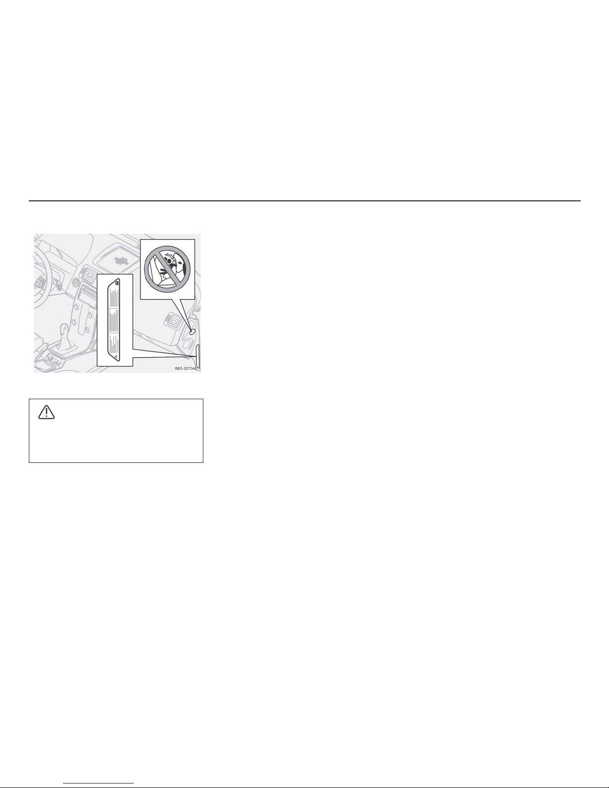
29
Safety
Decals on the side of the dashboard
WARNING!
Never place a child seat/booster
cushion on the front seat if the car has an
airbag on the passenger side.
Page 31

30
Safety
Position of children in the car
L: Suitable for certain child seats as listed in
the specified type approval. Child seats may
be vehicle-specific, limited, semi-universal or
universal.
Weight/age Front seat Outer rear seats Centre rear seat
<10 kg (22 lbs)
(0–9 months)
Rear-facing child seat, secured
with seat belt and mounting strap.
L: Type approval no. E5 03135
Rear-facing child seat, secured
with seat belt, support and
mounting strap.
L: Type approval no. E5 03135
Rear-facing child seat, secured
with seat belt, support and
mounting strap.
L: Type approval no. E5 03135
9-18 kg (19 – 40 lbs)
(9 –36 months)
Rear-facing child seat, secured
with seat belt and mounting strap.
L: Type approval no. E5 03135
Rear-facing child seat, secured
with seat belt, support and
mounting strap.
L: Type approval no. E5 03135
Rear-facing child seat, secured
with seat belt, support and
mounting strap.
L: Type approval no. E5 03135
15-36 kg (33 – 80 lbs)
(3-12 years)
Booster cushion with or without
backrest.
L: Type approval no. E5 03139
Alternatives:
Booster cushion with or without
backrest.
L: Type approval no. E5 03139
Integrated booster cushion.
L: Type approval no. E5 03168
Booster cushion with or without
backrest.
L: Type approval no. E5 03139
WARNING!
• Never place a child in a child seat or on
a booster cushion on the front seat if
the passenger seat airbag is activated.
• Never leave children unattended.
Page 32

31
Safety
ISOFIX mounting system for
child seats (option)
The outer rear seats are fitted with ISOFIX
mountings. Contact a Volvo dealer for further
information on child safety equipment.
Integrated booster cushions
(option)
Volvo’s integrated booster cushion for the
rear outer seats is specially designed to
provide optimum safety for children.
Combined with the regular seat belts, the
booster cushion is approved for children
weighing between 15 and 36 kg. (33 – 80
lbs).
Raising the booster cushion
1. Pull the handle to raise the booster
cushion.
2. Grasp the cushion with both hands and
move it backwards.
3. Press until it locks.
Check that:
• the seat belt is in contact with the
child’s body and is not slack or twisted
over the shoulder
WARNING!
The booster cushion must be in the
locked position before a child is placed
there.
Page 33

32
Safety
• the lap belt is low over the pelvis for
optimum protection
• the seat belt does not touch the child’s
throat or lie below the shoulders.
Carefully adjust the position of the head
restraint to suit the child.
See also page 158.
Lowering
1. Pull the handle
2. Move the seat down and press until it
locks
NOTE! Remember to first stow the
booster -cushion if you wish to lower the
seat’s backrest.
Replacing the booster cushion
It is important that the integrated booster
cushion is properly secured. Therefore,
replacement and any repairs to the cushion
should be carried out by a Volvo workshop.
Do not modify or adapt the booster cushion
in any way.
Installing the child seat
Volvo has child safety products that are
designed for and tested by Volvo.
WARNING!
If an integrated booster cushion has
been exposed to a major load, in a
collision for example, the entire booster
cushion must be replaced. This includes
the seat belt, complete with bolts. Even
if the booster cushion appears
undamaged, some of the protective
properties may have been lost. The
booster cushion must be replaced if it is
worn.
When using other products that are available
on the market, it is important to read the
installation instructions that accompany the
product and to follow them carefully.
• Do not attach the child seat straps to
the horizontal adjustment bar, springs or
the rails and struts under the seat.
Sharp edges may damage the mounting
straps.
• Allow the backrest of the child seat to
rest against the dashboard. This applies
to cars that do not have a passenger
side airbag or if the airbag is
deactivated.
• Never place a child seat on the front
seat if the car has a passenger side
airbag that is not deactivated. If there
are any problems with installation of
child safety products, contact the
manufacturer for clearer installation
instructions.
Page 34

33
Instruments and controls
Instruments and controls
Combined instrument panel 34
Check and warning symbols 35
Information display 39
Electrical socket and switch for the centre
console 40
Lighting panel 41
Left-hand steering wheel stalk 43
Cruise control (option) 45
Right-hand steering wheel stalk 46
Steering wheel adjustment, hazard warning
flashers 48
Parking brake, electrical socket 49
Power windows 50
Rearview/Door mirrors 52
Power sunroof (option) 55
Personal preferences 57
Page 35

34
Instruments and controls
1. Speedometer
2. Direction indicators, left
3. Warning symbol
4. Information display
The display presents information and
warning messages, outside temperature
and clock. When the temperature is
between +2 °C and –5 °C, a snowflake
symbol is shown in the display. This
symbol serves as a warning for slippery
road surfaces. When the car has been
stationary, the outside temperature
gauge may display a higher reading than
the actual temperature.
Combined instrument panel
5. Information symbol
6. Direction indicators, right
7. Tachometer
Indicates engine speed in thousands of
revolutions per minute (RPM). Do not
allow the needle of the tachometer to
enter the red field.
8. Check and warning symbols
9. Fuel gauge
10. Button for the trip odometer
Used to measure short distances. Briefly
pressing the button switches between
the two trip odometers T1 and T2. A long
press (more than 2 seconds) resets the
activated trip odometer.
11. Display
Displays the gear positions for automatic
gearbox, rain sensor, trip and odometer
and cruise control.
12. Main beam indication
13. Button for the clock
Turn the button to set the time.
14. Temperature gauge
The temperature of the engine cooling
system. If the temperature is abnormally
high and the needle enters the red zone,
a message is shown in the display. Bear
in mind that extra lamps in front of the air
intake reduce the cooling capacity at
high outside temperatures and high
engine loads.
15. Check and warning symbols
Page 36

35
Instruments and controls
Function test, symbols
All the check and warning symbols light when
the ignition key is turned to position II before
starting. The operation of the symbols is then
verified. All the symbols should go out when
the engine is started, apart from the
handbrake symbol which only goes out when
the handbrake is disengaged.
If the engine is not started within 5 seconds,
all symbols go out except for and .
Certain symbols may not have the function
indicated, depending on the car’s
specification.
Check and warning symbols
Symbols in the centre of the
dashboard
The red warning triangle is lit
when a fault has been indicated
that can affect safety and/or the
car's driveability. Explanatory
text appears in the information
display at the same time. The
warning symbol can also be lit
in combination with other
symbols.
1. Stop in a safe place. The car should not
be driven any further.
2. Read the information in the display.
3. Remedy according to the instructions or
contact a Volvo workshop.
If there is a deviation in one of
the systems in the car, the yellow
information symbol lights up in
combination with text in the
display. The information symbol
can also be lit in combination
with other symbols.
NOTE! The car can be driven for a further
period following a service-related message.
Consult your Volvo workshop.
Page 37

36
Instruments and controls
Indicator symbols - left-hand
side
1. Fault in the emissions system
Drive to a Volvo workshop to have
the system checked.
2. Fault in the ABS system
The system is not working if the
symbol lights. The car’s normal
braking system continues to work,
but without the ABS function.
1. Stop the car in a safe place and
switch off the engine.
2. Restart the engine.
3. If the symbol remains lit, drive to a
Volvo workshop to have the ABS
system checked.
3. Rear fog lamp
This symbol lights when the fog
lamp is on.
4. Stability system STC or DSTC
The flashing symbol indicates that
the stability system is in operation.
If the warning symbol remains lit,
this indicates low road friction.
5. No function
6. Engine preheater (diesel)
The symbol is lit while the engine
is being preheated. Preheating
starts when the temperature falls
below -2 °C. The car can be
started when the lamp goes out.
7. Low level in the fuel tank
There are approximately 8 litres
left when this symbol is lit.
Indicator symbol - right-hand
side
1. Trailer indicator lamp
The symbol flashes when the
direction indicators of the car and
trailer are used. If the symbol does
not flash, one of the lamps on the
trailer or car is defective.
2. Parking brake applied
The symbol lights even if the
parking brake has only been
applied one “click”. Check that
the lever is properly applied.
Page 38

37
Instruments and controls
3. Airbags - SRS
If the symbol remains lit or lights
while driving, a fault has been
detected in the SRS, SIPS or IC
system. Drive to an authorised
Volvo workshop as soon as
possible to have the system
checked.
4. Low oil pressure
If the symbol lights while driving,
the engine oil pressure is too low.
Stop the engine immediately and
check the engine oil level. Top up
if necessary. If the symbol is lit and
the oil level is normal, contact a
Volvo workshop.
5. Seat belt reminder
The symbol remains lit if the driver
or front passenger is not wearing
their seat belt.
6. Generator not charging
If this symbol lights while driving,
there is a fault in the electrical
system. Contact a Volvo
workshop.
7. Fault in the brake system
If the symbol lights, the brake fluid
level may be too low.
1. Stop the car in a safe place and
check the brake fluid reservoir
level.
2. If the reservoir level is below MIN,
the car should not be driven
further. Have the car recovered to
a Volvo workshop to have the
brake system checked.
If the BRAKE and ABS symbols
light at the same time, there may
be a problem in the brake forcedistribution.
1. Stop the car in a safe place and
switch off the engine.
2. Restart the engine.
• If both symbols go out, continue driving.
• If the symbols remain lit, check the brake
fluid reservoir level.
• If the brake fluid level is normal and the
symbols remain lit, carefully drive the car
to a Volvo workshop to have the brake
system checked.
• If the reservoir level is below MIN, the
car should not be driven further. Have
the car recovered to a Volvo workshop
to have the brake system checked.
Reminder - doors not closed
If one of the doors, the bonnet or the boot lid
is not correctly closed, the driver will be
warned.
Low speed
While the car is moving at a
maximum of 7 km/h (4.5 mph), the
symbol lights. At the same time,
one of the following will appear in
the display: DRIVER DOOR
OPEN, PASSENGER DOOR
OPEN, LEFT REAR DOOR
OPEN or RIGHT REAR DOOR
OPEN. Stop the car as soon as it
is safe to do so. Close the door or
the hatch which is open.
High speed
If the car is being driven at 7 km/h
(4.5 mph) or more, the symbol
lights. At the same time one of the
texts in the previous paragraph is
displayed.
WARNING!
If the BRAKE and ABS symbols light at
the same time, there is a risk that the rear
end will slide during heavy braking.
Page 39

38
Instruments and controls
Bonnet 1 and boot lid
Irrespective of speed, the symbol
lights and the display shows
BONNET OPEN or BOOT LID
OPEN.
1
Only cars with an alarm.
Page 40

39
Instruments and controls
Message Specification
STOP SAFELY Stop the car and switch off the engine. Serious risk of damage.
STOP ENGINE Stop the car and switch off the engine. Serious risk of damage.
SERVICE URGENT Take your car in for service immediately.
SEE MANUAL Read the owner's manual.
SERVICE REQUIRED Take your car in for service as soon as possible.
TIME FOR REGULAR SERVICE Time for service. The time is affected by the distance travelled, number of
months since last service and engine running time.
Information display
Messages
At the same time as a warning or indicator
symbol is lit, a supplementary message
appears in the information display.
• Press the READ button (A).
Scroll between the messages using the
READ button. Fault messages are stored in
the memory until the fault has been remedied.
NOTE! If a warning message is displayed
when the trip computer is being used, the
message must be read (press the READ
button) before the previous activity can be
resumed.
Page 41

40
Instruments and controls
Electric socket, DSTC system, extra
equipment
12V electric socket
The electric socket can be used for different
12 V accessories, such as mobile phones
and coolers. The maximum current is 10A. In
order for the socket to supply current, the
ignition key must be in position I.
WARNING!
Always leave the plug in the socket when
the socket is not in use.
Electrical socket and switch for the centre console
Cigarette lighter (option)
The lighter is activated by pushing in the
button. Once the lighter has been heated, the
button pops out again. Pull out the lighter and
use the heated coils.
Stability system STC or DSTC
1
The stability and traction control system is
activated automatically when the car is
started.
To reduce the stability control system:
• Hold the button pressed for at least half
a second.
For further information, see page 138.
Extra equipment
Space for extra switch for post installed
equipment.
1
Option in certain markets
WARNING!
The driving characteristics of the car
differ if the stability control system
function is reduced.
Page 42

41
Instruments and controls
1. Headlamp levelling
The headlamp height is adjusted using this
control. This is used when the car is so
heavily laden that it affects the height of the
beams.
• Normal beam height - move the control
upwards (0).
• Lowered beam height - move the control
downwards.
Cars with Bi-Xenon lighting (option) have
automatic headlamp levelling.
Lighting panel
2. Headlamps and position/
parking lamps
All lighting off.
Cars with daytime running
lights (certain countries)
Dipped beam lights automatically
when the ignition key is switched to the
driving position (II) and cannot be switched
off. Before trips to certain countries, the
daytime running lights can be deactivated.
Contact a Volvo workshop. Front and rear
parking lamps, number plate lighting and
instrument lighting are lit at the same time as
dipped beam.
Position/parking lamps
Front and rear position/parking
lamps as well as number plate
lighting and instrument lighting.
Main and dipped beam
Ignition key in position II:
Headlamps (plus front and rear
parking lamps, number plate
lighting and instrument lighting)
are lit.
NOTE! The light switch must be turned to
position II to switch on the main beam.
However, it is possible to flash the main beam
in all positions, even when the key is not in the
ignition switch. See also page 43.
3. Instrument lighting
Manual adjustment:
• Brighter illumination - move the control
upwards.
• Weaker illumination - move the control
downwards.
Automatic control:
A twilight sensor automatically adjusts the
brightness of instrument illumination.
4. Fog lamps (option)
Ignition key in position II:
• Press the button.
The fog lamps light in combination with
the position/parking lamps and main/
dipped beam. The LED in the button is
lit while the fog lamps are on.
NOTE! In some countries, dipped beam or
main beam may not be used in combination
with front fog lamps.
5. Fuel filler flap
• Press the button to open the flap
covering the fuel cap.
Page 43

42
Instruments and controls
6. Rear fog lamp
Ignition key in position II:
• Press the button to switch the fog tail
lamp on. The rear fog lamp lights in
combination with the main/dipped
beam. The LED in the button and the
symbol in the combined instrument
panel light. If the front fog lamps and the
main or dipped beam are switched off
and on again, the rear fog lamp goes
out. Press the button to switch it on
again.
Dazzling
Remember to switch off the fog tail lamp
when a car is seen in the rear view mirror.
Only the last car in a queue should have the
fog tail lamp switched on.
NOTE! Regulations for use of front and rear
fog lamps vary from country to country.
Page 44

43
Instruments and controls
Direction indicators, light switch
and main beam flash
Resistance point position (1)
When changing lanes or overtaking, move
the lever until you feel a distinct resistance.
The lever returns when released. This action
results in three flashes.
Normal turns (2)
The direction indicators light when you move
the lever in the direction the wheel moves
during the turn. When the steering wheel
returns to centre after a turn, the direction
indicators switch off automatically.
Left-hand steering wheel stalk
Main beam flash (3)
Pull the lever towards you (until you feel a
slight resistance). The main beam remains lit
until the lever is released.
Switching, main and dipped beam (3)
Pull the lever towards you past the flash
position and release it to change between
main and dipped beam.
Home safe light (3)
Carry out the following when you leave your
car when it is dark outside or when there is
poor visibility:
1. Remove the key from the ignition switch.
2. Move the steering wheel lever towards
you.
3. Exit the car.
4. Lock the doors.
The dipped-beam lighting, position/parking
lights, number plate lighting and door mirror
lamps (option) will switch on. These lamps
will remain lit for 30, 60 or 90 seconds. The
desired time setting can be adjusted in the
Car settings menu in the centre console
display. See the Personal Settings section for
further information.
Trip computer
Controls
In order to gain access to the information in
the trip computer, the thumbwheel INFO (B)
must be turned in steps, either upward or
downward. By turning again, you return to the
starting point.
NOTE! If a warning message interrupts while
the trip computer is in use, the message must
be acknowledged. Acknowledge by pressing
the READ button (A) and to revert to the trip
computer function.
Page 45

44
Instruments and controls
Functions
The trip computer receives a great deal of
data that is continuously evaluated by a
microprocessor.
The system has four functions which are
shown in the display:
• Average speed
• Current fuel consumption
• Average fuel consumption
• Range to empty fuel tank
Average speed
When the ignition is switched off, the
average speed is stored and used as the
basis of the new value when you continue
driving. Reset using the RESET button (C).
Current fuel consumption
Present fuel consumption is calculated every
second. The information in the display is
updated every couple of seconds. When the
car is stationary, “----“ appears in the display.
Average fuel consumption
The average fuel consumption since the last
reset (RESET). When the ignition is switched
off, the average fuel consumption is stored
and remains until the function is reset. Reset
using the RESET button (C).
NOTE! Some incorrect readings may occur if
a fuel-driven heater is used.
Range to empty fuel tank
This calculation is based on the average fuel
consumption over the last 30 km (19 miles)
and the remaining fuel volume. It displays the
approximate distance that can be driven with
the fuel remaining in the tank. When the
range to empty is less than 20 km (12 miles),
“----“ is shown in the display.
NOTE! Some incorrect readings may occur if
a fuel-driven heater is used.
Resetting
Keep the RESET button (C) pressed for at
least five seconds to reset the average speed
and average fuel consumption at the same
time.
Page 46

45
Instruments and controls
Operation
Activating
The controls for cruise control are to the left
of the steering wheel.
Setting the desired speed:
• Press the CRUISE button. CRUISE is
displayed.
• Increase or decrease the speed by
pressing + or –.
NOTE! Cruise control cannot be
engaged at speeds below 35 km/h (22
mph).
• Lightly press + or – to lock the desired
speed.
Cruise control (option)
CRUISE ON is displayed when the cruise
control is activated.
Temporary disengagement
• Press 0 to temporarily disengage the
cruise control.
Cruise control is automatically disengaged:
• if the speed drops below the limit for
engagement
• when the brake pedal or the clutch
pedal is depressed.
• if the gear selector is moved to position
N
• during wheel spin or wheel lock-up.
The last set speed is stored in the memory.
Return to the set speed
Press the button to resume the
previously set speed.
Acceleration
A temporary increase in speed, during
overtaking for example, does not affect the
cruise control setting. The car will resume the
previously set speed afterwards. If cruise
control is engaged, the speed can be
increased or decreased using the + or –
button.
A short press corresponds to approximately
1 km/h (0.6 mph). The speed of the car at the
time the button is released will be
programmed instead.
Disengagement
• Press CRUISE to disengage the cruise
control. CRUISE ON will go out in the
display. The cruise control is
automatically disengaged when the
ignition is switched off.
Page 47

46
Instruments and controls
Windscreen wipers
A. Windscreen and headlamp washers
B. Rain sensor - on/off
C. Thumb wheel
D. No function
Windscreen wipers off
The windscreen wipers are off
when the stalk is in position
Single sweep
Move the stalk up to make a single
sweep.
Right-hand steering wheel stalk
Intermittent wiping
The number of sweeps per time
unit can be adjusted. Turn the
thumb wheel (C) upwards for a
shorter interval between the
sweeps. Turn downwards to
increase the interval.
Continuous wiping
The wipers sweep at normal
speed
The wipers sweep at high speed
A – Windscreen/ headlamp
washers
Pull the lever towards the steering wheel to
start the windscreen and headlamp washers.
The wipers will make three more sweeps
once the stalk is released.
Headlamp washing
(option in certain markets)
High pressure washing of the headlamps
consumes a large quantity of washer fluid. To
save fluid, the headlamps are only washed
every fifth time (within a ten minute interval).
When ten minutes has passed since the last
time the windscreen was washed, the
headlamps are washed again at high
pressure the next time the windscreen is
washed.
B – Rain sensor (option)
The rain sensor detects the amount of water
on the windscreen so that the speed of the
windscreen wipers increases or decreases.
The sensitivity of the rain sensors is adjusted
using the thumb wheel (C).
On/Off
When activating the rain sensor, the
windshield wiper stalk must be in position 0.
To activate the rain sensor:
• press the button (B). The rain sensor
symbol is shown in the lower display.
Page 48

47
Instruments and controls
To switch off the rain sensor, either:
• press the button (B)
• change the wiper program by moving
the stalk to another position.
The rain sensor switches off automatically
when the ignition is switched off.
C – Thumb wheel
The thumb wheel is used to adjust the
number of sweeps per interval when
Intermittent wiping is selected or the
sensitivity to rainfall when the rain sensor is
selected.
D - Wiper and washer, rear
window
Wash and wipe are activated on the rear
windshield by moving the stalk forward. The
wiper blade will make a few more sweeps
once washing is complete.
The button on the end of the stalk is a three
position switch:
IMPORTANT!
Disengage the rain sensor at automatic
car washes or switch off the ignition. The
windshield wipers start and may become
damaged.
Intermittent wiping:
• Press in the top section of the switch.
Regular speed:
• Press in the lower section of the switch.
Neutral position:
• The function is deactivated.
Page 49

48
Instruments and controls
Steering wheel adjustment
The steering wheel can be adjusted for both
rake and reach.
1. Fold down the lever by the steering
column to release the steering wheel.
2. Adjust the steering wheel to the position
that suits you best.
3. Fold the lever back to secure the
steering wheel position. If the lever is
hard to move, press on the steering
wheel at the same time as pressing the
lever back.
Steering wheel adjustment, hazard warning flashers
Hazard warning flashers
Use the hazard warning flashers (all direction
indicators flash) when the car is stopped
where it could be a possible traffic hazard or
obstruction. Press the button to activate the
function.
NOTE! Regulations for use of hazard warning
flashers vary from country to country.
WARNING!
Adjust the steering wheel before driving,
never while driving. Before driving,
check that the steering wheel is fixed in
position.
Page 50

49
Instruments and controls
Parking brake ( handbrake)
The lever is located between the front seats.
The parking brake holds the rear wheels. The
warning symbol in the combined instrument
panel lights when the brake is applied.
The warning symbol lights even if the parking
brake has only been applied one “click”.
Check that the lever is properly applied.
To release the parking brake:
• Pull the lever up slightly and press in the
button. Lower the lever and release the
button.
Parking brake, electrical socket
Electric socket in the rear seat
The electric socket can be used for various
accessories, such as mobile phones and
coolers. It is intended for 12 V. The maximum
current is 10A. The ignition key must be in the
lowest position I for the socket to supply
current.
WARNING!
Always leave the plug in the socket when
the socket is not in use.
Cigarette lighter (option)
Press the lighter in to activate the function.
Once the lighter has been heated, it pops out
again. Pull out the lighter and use the heated
coils.
Page 51

50
Instruments and controls
Operation
The power windows are operated using the
controls in the door armrests. The ignition key
must be in position
or for the power
windows to work. Once you have stopped
driving and removed the ignition key, the
windows can still be opened or closed as
long as neither of the front doors are opened.
To open the window:
• Depress the front section of the control.
To close the window:
• Pull the front section of the control up.
Remote control and central locking
buttons
All side windows can automatically be
opened/closed using the remote control or
the central locking buttons:
• Hold the lock button pressed for two
seconds - the windows open or close.
If you need to interrupt opening/closing:
• Press the lock button again.
WARNING!
Ensure that children's or other
passengers' hands are clear when
closing the windows.
Power windows
A. Front door windows B. Rear door
windows
Driver's door
The driver can control all the power windows
from his seat.
The windows in the front doors can be
opened and closed in two ways:
1. Press one of the controls (A) or (B)
down gently or pull it up gently. The
power windows go up or down as long
as the switch is actuated.
2. Press one of the controls (A) or (B)
down fully or pull it up fully, then release.
The windows then open or close
automatically. Movement is stopped if
the window is blocked in any way.
Blocking power windows in the rear
doors
The LED in the switch is unlit
Rear door windows can be operated both by
the controls on the doors and the control on
the driver’s door.
The LED in the switch is lit
Rear door windows can only be operated
from the driver’s door.
WARNING!
If the rear door windows are being
operated from the driver’s door, check
that no rear seat passengers are in
danger of getting caught when the
windows close.
Page 52

51
Instruments and controls
NOTE! If the car has electric child safety
locks
1
the LED indicates that these are
activated. The doors cannot then be opened
from the inside.
1
Option
WARNING!
Always remember to switch off the
current to the power windows (i.e.
remove the ignition key) if children are
left in the car unattended.
Passenger seat, front
The control for the power window at the
passenger seat operates that window only.
Power windows in the rear
doors
The rear door windows can be operated with
the controls on the doors or the switch on the
driver’s door.
If the LED in the switch for blocking power
windows in the rear doors (located in the
control panel in the driver’s door) is lit, the
rear door windows can only be operated from
the driver’s door.
The windows in the rear doors are operated
in the same way as the windows in the front
doors.
Page 53

52
Instruments and controls
Rearview mirror
Dimming
Dimming is performed with the lever (1).
2. Normal position
3. Dimming position. Used when the light
from the vehicle behind is intrusive.
Dimming, automatic dim function
(option)
A sensor (4) in the bottom edge of the mirror
detects light coming from behind, and dims
the mirror when the light is strong. A Volvo
workshop can adjust the sensitivity.
NOTE! The illustration is a montage. The
mirror has either manual or automatic
dimming, never both at the same time.
Rearview/Door mirrors
Rearview mirror with compass
(option)
The upper right-hand corner of the rearview
mirror has an integrated display that shows
the compass direction in which the front of
the car is pointing. Eight different illustrations
are displayed with English abbreviations: N
(North), NE (North East), E (East), SE (South
East), S (South), SW (South West), W
(West) and NW (North West).
Calibrating the compass
The compass may need to be calibrated in
special cases. (installing weatherstrip). If
calibration is required, the character C
appears in the mirror's display.
1. Stop the car in a large, open area.
2. Start the car.
3. Hold the button (1) depressed (use a
pen, for example) for at least six
seconds. The character C will be
displayed again.
4. Drive slowly in a circle at a maximum
speed of 10 km/h (6 mph) until a
compass direction is displayed.
5. Calibration is complete.
Page 54

53
Instruments and controls
Magnetic zones
Adjusting the zone
The earth is divided into 15 magnetic zones.
The compass is adjusted for the
geographical area to which the car was
delivered.
Select a different compass area as follows:
1. Turn on the ignition.
2. Hold the button (1) depressed (use a
pen, for example) for at least 3 seconds.
The number for the current area is
displayed.
3. Press the button repeatedly until the
number for the required geographical
area (1-15) is displayed.
4. A few seconds after browsing is
complete, the display reverts to the
compass direction.
Door mirrors
The controls for setting the door mirrors are
at the front of the armrest on the driver’s door.
1. Press the L button for the left-hand door
mirror or R for the right-hand door
mirror. The LED in the button lights.
2. Adjust the position with the adjustment
control in the centre.
3. Press the L or R button again. The LED
should no longer be lit.
Retractable power door mirrors
(option)
The mirrors can be retracted for parking/
driving in narrow areas.
• Press the L and R buttons at the same
time. Release them after approximately
one second. The mirrors automatically
stop in the fully retracted position.
Fold out the mirrors
• Press the L and R buttons at the same
time. The mirrors automatically stop in
the fully extended position.
IMPORTANT!
Do not use ice scrapers with steel blades
to remove ice from the mirrors as the glass
could be scratched. Use the defroster
function instead. See the Climate Control
section for more information.
WARNING!
The driver's side mirror is wide angled to
provide optimal vision. Objects may
appear further away than they actually
are.
Page 55

54
Instruments and controls
Resetting to the neutral position
Mirrors that have been moved out of position
as a result of external influences must be
reset to the neutral position in order for
electric folding to function.
Proceed as follows:
• Fold in the mirrors using the L and R
buttons.
• Fold out the mirrors again using the L
and R buttons. The mirrors are now
reset to the neutral position.
Approach lighting
The lamps on the door mirrors light when
home safe lighting or approach lighting is
selected.
Page 56

55
Instruments and controls
Opening positions
The sunroof controls are located in the
headlining. The sunroof can be opened to
two positions:
• Ventilation position, raised at the rear
edge (A)
• Sliding position, backwards/forwards
(B)
The ignition key must be in position I or II.
WARNING!
Remember to switch off the current to
the sunroof (remove the ignition key) if
children are left in the car unattended.
Power sunroof (option)
1. Opening, automatic
2. Opening, manual
3. Closing, manual
4. Closing, automatic
5. Opening, ventilation position
6. Closing, ventilation position
Ventilation position
Open:
• Push the trailing edge of the control (5)
upward.
Close:
• Pull the trailing edge of the control (6)
downward.
From ventilation position to fully open sun
roof:
• Pull the control backwards to the end
position (1) and release.
Sliding position
Automatic operation
Pull the control over the resistance point
position (2) to the rear end position (1) or
over the resistance point position (3) to the
forward end position (4) and release. Sun
roof opens/closes fully.
Manual operation
Open:
• Pull the control backwards to the
resistance point position (2). The
sunroof will move towards maximum
opening position as long as the button
is held in.
Close:
• Press the control forwards to the
resistance point (3). The sunroof will
move towards the closed position as
long as the button is held in.
WARNING!
The sunroof's pinch protection function
only operates during automatic closing,
not manual closing.
Page 57

56
Instruments and controls
Closing using the remote
control or the central locking
button
Closing using the remote control or the
central locking button:
• Hold the lock button pressed for two
seconds. The sunroof and windows
close. The doors lock.
If you need to interrupt closing:
• Press the lock button again.
Sun screen
The sunroof features a manually-operated
sliding inner sun screen. The sun screen
slides back automatically when the sunroof is
opened. Grip the handle and slide the screen
forwards to close the screen.
Pinch protection
The sunroof pinch protection function is
activated if the hatch is blocked by an object.
If blocked, the sunroof will stop and
automatically open to the previous position.
WARNING!
The sunroof's pinch protection function
only operates during automatic closing,
not manual closing.
Make sure that children's hands are
clear when closing the sunroof.
Page 58

57
Instruments and controls
General
Personal preferences are available for some
of the car's functions. Applies to locks-,
climate control and audio functions. For audio
functions, see page 167.
Control panel
A. Display
B. MENU
C. EXIT
D. ENTER
E. Navigation
Use
The settings are presented in the display (A).
Open the menu to enter settings:
1. Press the MENU (B).
2. Scroll to Car Settings using the
navigation button (E).
3. Press ENTER (D).
4. Select an alternative using the
navigation button (E).
5. Confirm your selection with ENTER.
Close the menu:
• Press EXIT (C).
Personal preferences
Control panel
Possible settings
Personal preferences can be entered for
climate, locks and audio functions. For audio
functions, see page 167
Lock functions
Lock Feedback Light
When the car is locked/unlocked using the
remote control, the hazard warning flashers
can be selected to flash. The alternatives On/
Off are available for both locking and
unlocking.
Autolock
When the car starts to move, the doors and
boot lid can be locked automatically. The
alternatives On/Off are available.
Unlock
There are two alternatives for unlocking:
1. Global (all doors). Unlocks all doors with
one press on the remote control.
2. Two Step (two step unlocking). Unlocks
the driver's door with one press on the
remote control. Another press unlocks all
the doors.
Approach light
Selects the time the car's light should remain
lit when pressing the Approach Light button
on the remote control. The following options
can be selected: 30/60/90 seconds.
Page 59

58
Instruments and controls
Home safe light
Selects the time the car's light should remain
lit when the left-hand steering wheel stalk is
pulled backwards after the ignition key has
been removed.
The following options can be selected: 30/
60/90 seconds.
Information
• The VIN (Vehicle Identification Number)
is the car's unique identity number.
• Number of Keys The number of keys
registered for the car is displayed here.
Climate functions
Auto blower adjust (Automatic fan
adjustment)
The fan speed can be set to AUTO mode in
cars that have ECC:
• Select between Low, Normal and High.
Recirculation timer
When the timer is active, the air recirculates
in the car for 3-12 minutes depending on the
outside temperature.
• Select On/Off depending on whether
the recirculation timer should be active
or not.
Reset to factory settings
Resetting the climate function options to
factory settings.
Page 60

59
Climate control
Climate control
General information about climate control 60
Manual climate control, Air conditioning 62
Electronic climate control, ECC (option) 64
Air distribution 67
Fuel driven heater (option) 68
Additional heater (diesel) 70
Page 61

60
Climate control
Air conditioning – A/C
The climate control system cools or heats
and dehumidifies the air in the passenger
compartment. The car has either manual
(MCC) or automatic (ECC) climate control.
NOTE! The air conditioning can be switched
off, but for optimal air quality in the passenger
compartment and to prevent the windows
from misting it should always be on (even at
temperatures of 0-15°C.).
Misting on window interiors
Reduce the problem of fogging by wiping the
inside of the windows. Use a normal window
cleaner.
Ice and snow
Remove ice and snow from the climate
control air intake (the grille between the
bonnet and the windscreen).
Fault tracing
Your Volvo workshop has the instruments
and tools required for any fault tracing or
repair of your climate control system. Entrust
checks and repairs only to trained personnel.
General information about climate control
Refrigerant
Refrigerant R134a is in the air conditioning
system. This contains no chlorine, which
means it is harmless to the ozone layer. Only
use R134a when filling/changing refrigerant.
Have a Volvo workshop carry out this work.
Passenger compartment filter
All air which enters the passenger
compartment is cleaned by a filter. This must
be regularly replaced. Follow the Volvo
Service Programme for the recommended
replacement interval. If the car is used in a
severely contaminated environment, it may be
necessary to replace the filter more often.
NOTE! There are two different types of
passenger compartment ventilation filter.
Ensure that the correct filter is installed.
Display
There is a display above the climate control
panel. This is where the climate settings are
displayed.
Personal preferences
The climate control system can be set to two
functions:
• Fan speed to AUTO mode (only applies
to cars with ECC).
• Timer controlled recirculation of the air
in the passenger compartment.
For information about settings see page 57 .
Air vents in the dashboard
A. Open
B. Closed
C. Lateral airflow
D. Vertical airflow.
Aim the outer vents towards the front side
windows to remove misting.
Cold climates: Close the centre vents for the
most comfortable climate and best
demisting.
Page 62

61
Climate control
Condensation
In warm weather, condensation from the air
conditioning system may drip under the car.
This is normal.
ECC (option)
Actual temperature
The temperature you select corresponds to
the physical experience with reference to air
speed, humidity, exposure to sun, etc. which
affect the interior and exterior of the car.
Sensor placement:
• The sun sensor is on the upper side of
the dashboard.
• The temperature sensor for the
passenger compartment is behind the
climate control panel.
NOTE! Do not cover or block the sensors
with clothing or other objects.
Side windows and sunroof
To ensure that the air conditioning works
satisfactorily, close all the side windows and
the sunroof.
NOTE! Do not obstruct the ventilation holes
for the cargo compartment in the parcel shelf
with clothing or other objects.
Acceleration
The air conditioning system switches off
temporarily during full acceleration. You may
feel a temporary rise in temperature.
Page 63

62
Climate control
Control panel
1. Fan
2. Recirculation
3. Defroster
4. A/C - On/Off
5. Airflow to the floor
6. Airflow to head and body
7. Airflow to the windscreen
8. Heated front left seat
9. Heated front right seat
10. Rear window and door mirror defrosters
11. Temperature selector
Manual climate control, Air conditioning
Functions
1. Fan
Reduce the fan speed by
turning the knob.
If the knob is turned
anticlockwise and the fan
indication in the display
goes out, the fan and the air conditioning are
switched off. The display shows the fan
symbol and OFF.
2. Recirculation
Recirculation can be used
to shut out bad air, exhaust,
etc. from the passenger
compartment. The air in the
passenger compartment is
recirculated. No outside air is taken into the
car when this function is activated.
Recirculation (together with the air
conditioning system) cools the passenger
compartment more quickly in a warm climate.
If the air in the car recirculates for too long,
there is a risk of misting on the insides of the
windows.
Timer
The timer function minimises the risk of ice,
misting and bad air - when the recirculation
function is selected. See the “Personal
preferences” section page 58 to activate/
deactivate the function. Recirculation is
always disengaged when you select
Defroster (3).
3. Defroster
Defroster is used to quickly
remove misting and ice
from the windscreen and
side windows.
• Air flows to the windows at high fan
speed.
• The LED in the defroster button lights
when this function is activated. The air
conditioning system is controlled so that
there is maximum air dehumidification.
• The air is not recirculated.
Page 64

63
Climate control
4. A/C - On/Off
ON: Air conditioning is
connected.
OFF: Air conditioning (A/
C) system disconnected. If
Defroster (3) is activated
the air conditioning is
always engaged.
Manually selected airflow
Press one of the three buttons (5), (6) or (7).
Selected airflow is opened completely. A
symbol in the display above the climate
control panel and a lit LED in the relevant
button indicate that manual function has been
selected.
5. Airflow to the floor
Air to legs and feet.
6. Airflow to the head
and chest
7. Airflow to the
windscreen and side
windows
8 and 9. Heated front
seats
(option in certain markets)
10. Rear window and
door mirror defrosters
Heating is used to quickly
remove misting and ice
from the rear windscreen
and door mirrors.
Higher heat
level
Press the button once
- both LEDs light.
Lower heat
level
Press the button twice
- one LED lights.
Heat off Press the button three
times - no LEDs are lit.
11. Temperature
selector
Select cooling or heating
for both the driver's and
passenger sides.
Page 65

64
Climate control
1. Auto -On/Off
2. Fan
3. Recirculation
4. Defroster
5. Airflow to the floor
6. Airflow to head and body
7. Airflow to the windscreen
8. ECC - ON/OFF
9. Heated front seat, left
10. Heated front seat, right
Electronic climate control, ECC (option)
11. Rear window and door mirror defrosters
12. Temperature selector
Functions
1. Auto -On/Off
The AUTO function
automatically regulates
climate control so that the
desired temperature is
attained. The automatic
function controls heating,
air conditioning, fan speed, recirculation, and
air distribution. If you select one or more
manual functions, the other functions
continue to be controlled automatically. All
manual settings are switched off when AUTO
is switched on. The display shows AUTO
CLIMATE.
2. Fan
Fan speed can be
increased or decreased by
turning the knob. The fan
speed is regulated
automatically if AUTO is
selected. The previously
set fan speed is
disconnected.
NOTE! If the knob is turned anticlockwise
and the fan indication in the display goes out,
the fan and the air conditioning are switched
off. The display shows the fan symbol and
OFF.
3. Recirculation
This function can be used
to shut out bad air, exhaust
fumes etc. from the
passenger compartment.
The air in the passenger
compartment is
recirculated. No outside air is taken into the
car when this function is activated. If the air in
Page 66

65
Climate control
the car recirculates for too long, there is a risk
of misting on the insides of the windows.
Timer
The timer function minimises the risk of ice,
misting and bad air - when the recirculation
function is selected. See the “Personal
preferences” section to activate/deactivate
the function.
NOTE! Recirculation is always disengaged
when you select Defroster (4).
3. Air quality system (option)
(same button as recirculation)
The air quality system
consists of a multifilter and
a sensor. The filter
separates gases and
particles, reducing odour
and contaminants in the
passenger compartment. The air intake is
shut and the air is recirculated in the
passenger compartment if the sensor
detects contaminated outside air. When the
air quality sensor is active, the green LED (A)
in the button lights.
Activate the air quality sensor:
• Press the AUTO button (1) to activate
the air quality sensor (normal setting).
Or:
Select one of the following three functions by
pressing the recirculation button repeatedly.
• The air quality sensor is active - the LED
(A) lights.
• Recirculation is not activated unless
required for cooling in a warm climate no LED is lit.
• Recirculation is active - the LED (M)
lights.
Tip!
• Have the air quality sensor connected.
• Recirculation is limited in cold climates
to avoid misting.
• The air quality sensor should be
deactivated if the windows begin to
mist.
• If there is misting, use the defrosters for
the windscreen, rear windscreen and
side windows.
4. Defroster
Defroster is used to quickly
remove misting and ice
from the windscreen and
side windows. Air flows to
the windows at high fan
speed. The LED in the
defroster button lights when this function is
activated. The air conditioning system is
controlled so that there is maximum air
dehumidification. The air is not recirculated.
5. Airflow to the floor
Air to the legs and feet
6. Airflow to the head and chest
7. Air to the windscreen and side
windows
Page 67

66
Climate control
8. ECC ON/OFF
The air conditioning
system is controlled
automatically by the
system when the ON LED
is lit. This way, incoming air
is cooled and dehumidified
sufficiently. The air conditioning (A/C) system
is disengaged when the OFF LED lights.
Other functions are still controlled
automatically. When Defroster (4) is
selected, the air conditioning system is set for
maximum dehumidifying.
9 and 10. Heated front seats
(option in certain markets)
To heat the front seat:
Higher heat
level
Press the button once
- both LEDs light.
Lower heat
level
Press the button twice
- one LED lights.
Heat off Press the button three
times - no LEDs are lit.
11. Rear windscreen and door mirror
defrosters
Use the defroster to
remove ice and misting
from the rear window and
door mirrors.
The rear window and door mirrors are
defrosted simultaneously if the switch is
pressed once. The function is active if one
LED is lit in the switch. The door mirrors are
deactivated automatically after approximately
6 minutes. The rear windscreen is
deactivated after approximately 12 minutes.
12. Temperature selector
The temperatures on the
driver and passenger sides
can be set independently.
Both sides are activated when the car is
started. Only one side is activated if the
button is pressed once. If pressed again, only
the other side is activated. Both sides are
activated again if the button is pressed a third
time. The active side is indicated by an LED
in the button and in the display above the
climate control panel.
NOTE! Heating or cooling cannot be
hastened by selecting a higher or lower
temperature than the actual desired
temperature.
Page 68

67
Climate control
Air distribution
Air distribution Use: Air distribution Use:
Air to windows. There is
a certain amount of
airflow to the air vents.
The air is not
recirculated. Air
conditioning is always
connected.
to remove ice and
misting quickly.
Air to the floor and
windows. There is a
certain amount of
airflow to the air vents.
to ensure
comfortable
conditions and good
demisting in a cold or
humid climate.
Air to windows. to ensure efficient
cooling in a warm
climate. Prevents
misting and icing in
a cold climate.
Air to the floor and air
vents.
in sunny weather
with cool outside
temperatures.
Air to the windows and
dashboard air vents.
to ensure good
comfort in a warm
and dry climate.
Air to the floor. There is
a certain amount of
airflow to the air vents
and windows.
to warm the feet.
Air to the dashboard air
vents.
to ensure efficient
cooling in a warm
climate.
Air distribution
Page 69

68
Climate control
General information about
heaters
The parking heater can be started
immediately or set with two different start
times using TIMER 1 and TIMER 2. Here,
start time refers to the time the car should be
heated and ready. The car’s electronic
system calculates when heating should be
started based on the outside temperature.
There will be no heating if the outdoor
temperature exceeds 25°C. At temperatures
of –7°C and below, the maximum running
time of the parking heater is 60 minutes.
WARNING!
The car must be outdoors if using petrol
and diesel heaters.
Fuel driven heater (option)
Activating the heater
1. Enter the time when the car is to be
used. Press RESET (C) to enter the
hours and minutes when the car is to be
used.
2. Press RESET again. The timer is
activated.
Press RESET button to activate the Timer.
• The timer is activated: ON lamp lights
with a steady glow.
• The heater operates: ON lamp flashes.
Parking on a hill
If the car is parked on a steep incline, the
front of the car should point downhill to
ensure that there is a
supply of fuel to the parking heater.
Heater direct start
1. Use the thumb wheel (B) to scroll to
“DIRECT START”.
2. Press the RESET button (C) to make
ON and OFF selections available.
3. Select ON.
The heater will now run for 60 minutes.
The passenger compartment will begin
to heat up as soon as the engine
coolant has reached a temperature of
38°C
Immediate stop of heater
1. Use the thumb wheel to scroll to
“DIRECT START”.
2. Press the RESET button (C) to make
ON and OFF selections available.
3. Select OFF.
Battery and fuel
If the battery is not sufficiently charged or the
petrol level is too low, the parking heater will
be switched off automatically. A message
appears in the information display. Confirm
the message by pressing the READ button
(A).
IMPORTANT!
Repeated use of the parking heater
combined with short journeys may
discharge the battery and impair starting.
In order to ensure that the generator has
time to produce the energy required by
the heater without discharging the battery,
if the heater is used regularly the car must
be driven for a period equalling the time
during which the heater has been active.
Page 70

69
Climate control
Setting TIMER 1 and 2
For reasons of safety, you can only
programme times for the following 24 hours,
not several days in a row.
1. Use the thumb wheel to scroll to TIMER
2. Press the RESET button briefly to select
the flashing hours setting.
3. Use the thumb wheel to scroll to the
required hours.
4. Press the RESET button briefly to select
the minutes setting.
5. Use the thumb wheel to set the desired
minutes.
6. Press the RESET button briefly to
confirm the setting.
7. Press the RESET button to activate the
timer.
Once TIMER 1 has been set, a second start
time can be programmed in TIMER 2 which
is accessed using the thumb wheel. The
alternative start time is set in the same way
as with TIMER 1.
Messages in the display
Once the TIMER 1, TIMER 2 and Immediate
start settings are activated, the information
symbol in the combined instrument panel
lights and an explanatory text is shown in the
information display. The display indicates
which timer is active when the driver removes
the key from the ignition and is leaving the
car.
Car clock/timer
If the car clock is reset after the clocks in the
heater are programmed, the selected times
will be cancelled for safety reasons.
Page 71

70
Climate control
Additional heater
(certain markets)
In certain conditions, diesel cars may require
extra heating to ensure sufficient heating in
the passenger compartment. The additional
heater is fully automatic and only starts when
it is sufficiently cold.
When the additional heater is
running, it is indicated by an
information symbol on the
dashboard, combined with FUEL
HEATER ON, which flashes in
the display above the dashboard.
Additional heater (diesel)
Manual shut off
In certain situations it may be desirable to be
able to switch off the additional heater, such
as when refuelling.
• Press the READ button (A) once. The
heater switches off and FUEL HEATER
OFF is displayed.
WARNING!
• Switch off the fuel driven heater before
beginning refuelling.
• Spilled fuel could be ignited by the
exhaust gases.
• Check in the information display that
the heater is off.
Page 72

71
Interior
Interior
Front seats 72
Interior lighting 74
Storage compartments in the passenger
compartment 76
Rear seat 78
Cargo compartment 80
Warning triangle 81
Page 73

72
Interior
Seating position
The driver and passenger seats can be
adjusted to the optimum sitting and driving
positions.
1. Forwards/backwards, lift the handle to
set the correct distance to the steering
wheels and pedals. Check that the seat
has locked into position after adjusting.
2. Raise/lower the front edge of the seat
cushion, pump up or down (option)
3. Raise/lower the seat, pump up or down
(option)
4. Change the lumbar support, turn the
knob
Front seats
5. Change the angle of the backrest, turn
the knob
6. Control panel for power seats.
Position controls (2) and (3) are not fitted to
all seat models.
WARNING!
• Adjust the driver's seat position before
driving, never while driving.
• Check that the seat is locked in
position.
Position controls (2) and (3) are not fitted to
all seat models
Lowering the front seat backrest
(option)
The passenger seat backrest can be folded
forwards to make room for long loads.
1. Move the seat as far back as possible.
2. Set the backrest to 90°, the upright
position.
3. Lift the catches on the rear of the
backrest whilst folding it forwards.
Page 74

73
Interior
Power seat (option)
Preparations
The seat can normally only be adjusted if the
ignition - key is in position I or II. It can also be
adjusted within 10 minutes of the door being
unlocked with the key or remote control. If the
door is closed and the ignition key is not yet
in the ignition, or the ignition is in position 0,
settings can be made within 40 seconds of
the door being closed.
Memory function in the remote control
(option)
The remote control used to unlock the car
stores information about the seat settings
which are changed. The next time the car is
unlocked using the same remote control and
the driver’s door is opened within 2 minutes,
the driver’s seat will assume the stored
position.
Seats with memory function (option)
1. Seat setting, program 1
2. Seat setting, program 2
3. Seat setting, program 3
4. Storing seat settings
Three positions can be stored. After setting
the seat, hold the M button (4) pressed in
while pressing button (1). Further seat
settings can be stored in the memory using
the memory buttons (2) and (3).
Setting preset positions
Hold memory button (1), (2) or (3) pressed
until the seat stops. For safety reasons, the
seat will stop moving immediately if the
button is released.
Seat adjustment
The following can be set using the two
switches (5), (6) and (7):
5. Backrest rake
6. Seat forwards/backwards and up/down
7. Front edge of seat cushion up/down
Only one of the electric motors can be
operated at a time. The power seats have an
overload protector that activates if a seat is
blocked by any object. If this occurs, switch
off the ignition (key in position 0) and wait
about 20 seconds before using the seat
again.
Emergency stop
If the seat accidentally begins to move, press
one of the buttons to stop the seat.
WARNING!
• Ensure that there are no obstructions
in front of, behind or underneath the
seat when setting the position.
• Ensure that none of the rear seat
passengers will be trapped.
• To avoid injury, ensure that children
do not play with the switches.
Page 75

74
Interior
A. Lighting left-hand side. B. Switch.
C. Lighting right-hand side
Lighting front seat
The lighting in the front section of the
passenger compartment can be controlled
using the buttons in the roof console.
Three positions can be selected for lighting
the entire passenger compartment using
switch (B)
1. Off - left-hand side pressed, passenger
lighting off.
2. Neutral position - passenger
compartment lighting lit when a door is
opened and goes out when the door is
closed. The dimmer function is active.
3. On - right-hand side pressed, passenger
lighting lit.
Interior lighting
Automatic lighting
The interior lighting comes on and goes out
automatically when the switch (B), see the
illustration, is in the neutral position.
The lighting comes on and remains lit for 30
seconds when:
• the car is unlocked from the outside
using the key or remote control.
• the engine is stopped and the ignition
key is turned to the 0 position.
The lighting comes on and remains lit for five
seconds when:
• one of the doors is open
• the lighting is not switched off.
The interior lighting goes out when:
• the engine is started
• the car is locked from the outside using
the key or remote control.
The interior lighting goes out automatically
five minutes after the engine is switched off.
The interior lighting can be switched on or off
within 30 minutes of the key being turned to
position 0 by pressing the button (B) briefly.
The programmed times can be changed. See
the instructions in the section about
“Personal preferences” page 57 .
Lighting rear seat
Lamps can be switched on or off by pressing
the respective button. The lighting goes out
automatically ten minutes after the engine is
switched off.
Page 76

75
Interior
Vanity mirror
The lamp comes on automatically when the
cover is lifted.
Page 77

76
Interior
Storage compartments in the passenger compartment
Page 78

77
Interior
1. Centre console locker (also at the front
edge of the front seat, seat cushions.)
2. Door panel compartment
3. Ticket clip.
4. Glovebox.
5. Waste basket (accessory).
6. Storage compartment and cup holder.
7. Storage compartment and cup holder.
WARNING!
Waste paper basket (5) must not be
installed if the handset is mounted on the
right hand side of the centre console.
WARNING!
• Make sure that no hard, sharp or heavy
objects lie or protrude in such a way
that they could cause injuries during
heavy braking.
• Always secure large, heavy loads
with one of the seat belts or a
retaining strap.
Glovebox
The owners manual and maps can be stored
here. There are also holders for coins, pens
and fuel cards. The glovebox can only be
locked and unlocked using the detachable
key blade on the remote control. See the
Lock and Alarm section page 84 for further
information about the key.
Floor mats (option)
Volvo offers floor mats specially
manufactured for your car. They must be
firmly secured in the clips on the floor so that
they cannot slide and become trapped under
the pedals on the driver's side.
Page 79

78
Interior
IMPORTANT!
The head restraints can be damaged if
they are not removed when loading. The
centre head restraint must be removed
when transporting heavy loads.
Rear seat
Hanging up seat belts
Tipping the rear seat backrest
The rear seat backrests can be folded
forwards, either together or individually, to
make it easier to transport long objects. To
avoid damaging the seat belts when folding
the backrest up or down, they must be hung
on the grab handle hook.
• Hang the seat belt up before folding the
backrests up or down.
Adjust the head restraint vertically
Rear centre seat head restraint
All the head restraints can be adjusted
vertically to suit the height of the passenger.
The upper edge of the head restraint should
be aligned to the centre of the rear of the
head. Slide the head restraint up as desired.
Press the button on the right hand pillar of the
head restraint while pushing down to return
the head restraint to the down position. Press
the button on the right hand pillar of the head
restraint while pulling upwards to remove the
head restraint.
Page 80

79
Interior
Folding the backrest
1. Pull the straps to fold the seat cushions
forwards.
2. Pull the latches up and forward to
detach the backrest. A red mark on the
latches indicates that the backrest is not
in the locked position
3. Fold the backrest halfway forward and
remove the outer head restraints. The
head restraint in the centre seat must be
pressed down fully or removed
4. Place the head restraints in the plastic
sleeves on the bottom of the folded seat
cushions.
NOTE! The red indicator must not be visible
when the backrest is folded back into the
upright position. The backrest is not secure if
still visible.
WARNING!
Do not forget to remove the seat belt
from the hooks again when backrest has
been folded up.
Page 81

80
Interior
Cargo compartment safety grille
(option)
The protective grille prevents cargo or pets
from being thrown forward in the passenger
compartment in the event of heavy braking.
For reasons of safety, the grille must always
be mounted and secured correctly.
Folding up
If the cargo compartment safety grille is in the
way it can be easily folded up towards the
roof:
1. Take hold of the bottom of the cargo
compartment safety grille.\
2. Pull straight backwards and upwards.
Then release. The gas struts prevent the
grille from dropping down.
Cargo compartment
To fold down the grille carry out in reverse
order.
Removal
Remove the protective grille as follows:
1. Fold the rear seat backrest forward
slightly (to relieve the load from the gas
struts).
2. Remove the protective caps from the
nuts holding the cargo compartment
safety grille on both sides.
3. Unscrew the nuts until the threads are
flush with the edge of the nuts.
4. Turn the grille backwards in the car
slightly to release it from the upholstery.
Do not angle the grille too much as it
can become wedged, making it difficult
to pull out.
5. Carry out the same procedure on the
other mounting and then lift out the grille
carefully.
Fitting
To install the grille:
• Follow the instructions in reverse order.
• Tighten both the nuts. Tighten to 24 Nm.
If unsure about installing or removing
the protective grille, contact a Volvo
workshop for advice.
Privacy panel (option)
Pull the privacy panel over the cargo and
hook it into the holes in the rear pillars of the
cargo compartment.
Fitting the privacy panel:
• Press the end pieces of the privacy
panel down into the holders.
Removing the privacy panel:
• Press the end pieces of the privacy
panel inwards, pull up and release.
Page 82

81
Interior
Load retaining eyelets
1
The load retaining eyelets are used to secure
the restraining strap or net holding goods in
the cargo compartment.
1
Option in certain markets
Electrical socket in the cargo
compartment
Fold down the cover to access the electric
socket. This operates regardless of whether
the ignition is switched on or not.
If the ignition is switched off and load with a
power consumption higher than 0.1 A is
connected to the electric socket, a warning
message appears in the information display.
The maximum current for the electric socket
is 15A. Remember not to use the electric
socket when the ignition is switched off.
There is a risk of the battery being
discharged.
Grocery bag holder
The grocery bag holder holds bags in place
and prevents them tipping over and spilling
their contents in the cargo compartment.
• Fold up the hatch in the cargo
compartment.
• Hang or secure the grocery bags using
the tensioning strap or holders.
Page 83

6DIHW\QHWRSWLRQ
7KHVWRUDJHFDVVHWWHRIWKHH[WUDFWDEOHVDIHW\
QHWLVPRXQWHGRQWKHUHDURIWKHEDFNUHVW
Using the safety net with upright
backrest
f 3XOOWKHVDIHW\QHWVWUDLJKWEDFN
f 3XOORXWWKHULJKWPRXQWLQJDQGKROGLW
SXOOHGRXW,QVHUWWKHPRXQWLQJLQWKH
UHDUODUJHSDUWRIWKHKROHLQWKHURRI
SDQHOVUHDUEUDFNHW
f 7KHSXVKWKHPRXQWLQJIRUZDUGWRWKH
IURQWSDUWRIWKHKROH
f 'RWKHVDPHRQWKHRWKHUVLGH7KHQHW
PRXQWLQJVUHWUDFWLQZDUGVVRSXOOWKH
QHWRYHUWRWKHOHIWEUDFNHWWRILWLWLQ
SODFH
Cargo compartment
f &KHFNWKDWWKHVDIHW\QHWPRXQWLQJVDUH
SURSHUO\IDVWHQHGLQWKHURRISDQHO
EUDFNHWV
8VLQJZLWKIROGHGEDFNUHVW
f 7KHVDIHW\QHWFDQDOVREHXVHGZKHQ
WKHEDFNUHVWLVIROGHGGRZQ7KHURRI
SDQHOVIURQWEUDFNHWVDUHWKHQXVHG
5HPRYLQJWKHVDIHW\QHW
f 3XOOEDFNRQHRIWKHQHWPRXQWLQJVWR
WKHODUJHKROHDQGSXOOLWRXW
f 5HOHDVHWKHRWKHUPRXQWLQJWKHVDPH
ZD\
5HPRYLQJWKHVDIHW\QHWVWRUDJH
FDVVHWWH
f )ROGGRZQWKHHQWLUHEDFNUHVW
f 6OLGHWKHFDVVHWWHRXWZDUGVXQWLOLWLV
UHOHDVHGIURPWKHUHWDLQHUV
:$51,1*
&DUJRFRPSDUWPHQWORDGVPXVWEH
SURSHUO\VHFXUHGHYHQLIWKHVDIHW\QHWLV
FRUUHFWO\ILWWHG
Using the safety net together
with the privacy panel
f /RZHUWKHEDFNUHVWVOLJKWO\WRDFFHVV
WKHVDIHW\QHWFDVVHWWH6WDUWZLWKWKH
VHFWLRQ
f 3XOOWKHVDIHW\QHWEDFNDWDQDQJOH
f 5HVWRUHWKHEDFNUHVWWRLWVXSULJKW
SRVLWLRQ
f +RRNWKHQHWLQWRWKHURRISDQHO
EUDFNHWVIROORZLQJWKHSURFHGXUHXVHG
ZKHQWKHEDFNUHVWLVXSULJKW
127(:KHQWKHEDFNUHVWLVXSULJKWWKHUHG
LQGLFDWRUVKRXOGQRORQJHUEHYLVLEOH,ILWLV
YLVLEOHWKHEDFNUHVWLVQRWORFNHGLQSRVLWLRQ
Page 84

Page 85

82
Interior
Setting up the warning triangle
1
Follow the applicable regulations for the use
of warning triangles.
1. Release the cover containing the
warning triangle. It is secured with
Velcro.
2. Remove the warning triangle from its
case (A).
3. Fold out the four support legs on the
warning triangle.
4. Fold out both red sides of the warning
triangle. Place the warning triangle in a
1
Certain markets
Warning triangle
location that is appropriate for the traffic
situation.
After use:
1. Reinstall everything in reverse order.
2. Make sure the warning triangle and its
case are properly secured in the cargo
compartment.
Page 86

83
Locks and alarm
Locks and alarm
Remote control with key blade 84
Locking and unlocking 87
Child safety locks 89
Alarm (option) 90
Page 87

84
Locks and alarm
Remote control
The car is supplied with two remote controls.
These also work as ignition keys. The remote
controls contain detachable metal key blades
for mechanical locking/unlocking of the
driver's door and glove compartment. A
separate label with the code of the key blade
is supplied. Store the label in a safe place.
Take the label to a Volvo workshop when
ordering new keys. A maximum of six remote
controls/key blades can be programmed and
used for one car.
Loss of a remote control
If either of the remote controls is lost, the
other must be taken with the car to a Volvo
workshop. As a crime prevention measure,
the code of the lost remote control must be
erased from the system.
Immobilizer
The remote controls have coded chips. The
code must match the reader (receiver) in the
ignition switch. The car can only be started if
the correct remote control with the correct
code is used.
IMPORTANT!
Never use force on the narrow section of
the remote control - this is where the chip
is located. The car cannot be started if the
chip is damaged.
Remote control with key blade
Remote control functions
Locking - Locks all doors and the boot
lid. A long press also closes the side
windows and sun roof.
Unlocking - Unlocks all doors and the
boot lid. A long press also opens the
side windows.
Approach lighting - As you approach
the car:
Press the yellow button on the remote
control to light the interior lighting,
position/parking lamps, number plate
lighting and the lamps in the door
mirrors (option). The lighting switches
off automatically after 30, 60 or 90
seconds. To set the desired timer
setting, see page 58 .
Boot lid- Press the button once to
unlock the boot lid only.
Panic function- Used to attract
attention during emergency situations. If
the red button is held in for at least three
seconds or pressed twice within three
seconds, the direction indicators,
interior lighting and horn will be
activated. This function can be
deactivated using the same button after
it has been active for at least five
seconds. Otherwise it switches off after
30 seconds.
Key blade
This function is intended to be used when
handing over the car for servicing, or valet
parking at a hotel etc. The remote control is
handed over without the detached key blade,
which the owner keeps.
Page 88

85
/RFNVDQGDODUP
5HPRYLQJWKHNH\EODGH
2SHQWKHNH\EODGHRXWRIWKHUHPRWHFRQWURO
f 6OLGHWKHVSULQJORDGHGFDWFKWRWKH
VLGHZKLOVWSXOOLQJWKHNH\EODGHRXW
WRWKHUHDU
,QVWDOOLQJWKHNH\EODGH
%HFDUHIXOZKHQSXWWLQJWKHNH\EODGHEDFN
LQWRWKHUHPRWHFRQWURO
f +ROGWKHUHPRWHFRQWUROZLWKWKHSRLQWHG
HQGGRZQ5HOHDVHWKHNH\EODGHLQLWV
JURRYH
/RFNLQJSRLQWVQRUPDOSRVLWLRQ/RFNLQJ
SRLQWVVHUYLFHSRVLWLRQ
f *HQWO\SUHVVWKHNH\EODGHWRORFNLWLQ
SRVLWLRQ,WZLOOFOLFN
/RFNLQJWKHJORYHER[
7KHNH\EODGHLVXVHGWRORFNRUXQORFNWKH
JORYHER[7KHGULYHUVGRRUFDQDOVREH
ORFNHGRUXQORFNHGXVLQJWKHNH\EODGH
:HDNEDWWHU\LQWKHUHPRWH
FRQWURO
:KHQWKHEDWWHU\EHJLQVWRUHDFKWKHSRLQW
ZKHUHIXOOIXQFWLRQDOLW\FDQQRWEHJXDUDQWHHG
WKH,QIRUPDWLRQV\PEROOLJKWVDQG5(027(
%$77(5</2:92/7$*(LVVKRZQLQWKH
GLVSOD\
Page 89

86
Locks and alarm
Changing the remote control
battery
If the locks repeatedly fail to react to signals
from the remote control at a normal distance,
the battery should be replaced (type CR
2032, 3 volt).
1. Pull out the key blade.
2. Place the remote control with the
keypad downwards. Remove the screw
(1) using a small screwdriver.
3. Remove the cover.
4. Note how the + and – poles of the
battery are positioned on the inside of
the cover.
5. Pry out (2) and change the battery.
Avoid touching the battery and its
contact surfaces with your fingers.
6. Reinstall and screw the cover into place.
7. Press the key blade back into position.
Ensure that the old battery is disposed of in
an environmentally friendly way.
Page 90

87
Locks and alarm
Locking/unlocking from outside
the car
The remote control can be used to lock or
unlock all the car doors and the boot lid at the
same time. The doors can be unlocked using
the detached key blade.
Automatic re-locking
If none of the doors or the boot lid are opened
within two minutes of unlocking, all locks relock automatically. This function prevents the
car from unintentionally being left unlocked.
For cars with alarms, see the Alarm System
section.
Opening the boot lid
Carry out the following to unlock the boot lid
only:
• Press the boot lid button on the remote
control .
If all the doors are locked when the boot lid is
closed, it locks automatically.
WARNING!
Note that occupants can be locked
inside the car if it is locked from the
outside.
Locking and unlocking
Locking/unlocking from inside
the car
The switches in the door panel can be used
to lock or unlock all the doors and the boot lid
simultaneously.
• Unlocking:
Press in the upper section in the lock
button. A long press also opens all the
side windows.
•Locking:
Press in the lower section of the lock
button. A long press also closes all the
side windows and the sun roof.
The doors cannot be opened by pulling up
the lock button. All the doors can also be
locked manually using the relevant lock
button. This applies only if the car is not
locked from the outside. The doors can also
be unlocked using the opening handle.
This applies only if the car is not locked from
the outside. The doors can also be unlocked
(and door opened) using the handle.
Page 91

88
Locks and alarm
Locking the glovebox
The glovebox can only be locked and
unlocked using the detachable key blade on
the remote control.
1. Unlock the glovebox by turning the key a
quarter of a turn (90°) anti-clockwise.
The key hole is vertical when unlocked.
2. Lock the glove compartment by turning
the key a quarter of a turn (90°)
clockwise. The key hole is horizontal
when locked.
Deadlocks
When deadlocked, the doors cannot be
opened from the inside if they are locked.
1. Disconnecting the sensors. 2. No function.
Activated using the remote control.
Deadlocks are activated after 25 seconds
delay after the doors are locked. The car can
only be deadlocked using the remote control.
The doors can also be opened using the key
from the outside.
Temporary deactivation of
deadlocks and any detectors.
If others prefer to remain seated in the car
with the doors locked from the outside, the
deadlocks can be deactivated.
1. Insert the key in the ignition switch, turn
it to position II and then back to position
I or 0.
2. Press the button 1.
If the car is equipped with an alarm, the
movement and tilt detectors are also
deactivated. See page page 91.
The LED in the button lights until the car is
locked with the key or remote control. A
message is shown in the display as long as
the key remains in the ignition switch. The
next time the car ignition is switched on, the
sensors will be re-engaged.
WARNING!
Do not allow anyone to remain in the car
without first deactivating the
deadlocking.
Page 92

89
Locks and alarm
Manual lock in the left-hand rear door
Locks in the doors, rear
To lock manually: The controls for the child
safety locks are in the rear edges of the rear
doors and are only accessible when the door
is open. Use the key blade to turn the control
and thus activate or deactivate the child
safety locks.
A: The doors cannot be opened from the
inside.
B: The doors can be opened from the inside.
To lock electronically: Press the controls in
the driver's door. A message appears in the
information display.
Child safety locks
Electrical lock for opening the rear door and
window
WARNING!
Always keep the lock buttons up when
driving. In the event of an accident,
rescue personnel will then be able to
quickly get into the car. The rear seat
passengers cannot open the doors from
the inside if the child safety locks are
activated.
Lock in the window, rear
(option)
When the electric child safety locks are
active, the rear windows cannot be used.
Activate the child safety locks:
1. Turn the ignition key to position I or II.
2. Press the button. The rear windows
cannot be opened when the LED in the
button is lit.
A message will appear in the information
display when the child safety locks are
activated.
NOTE! When the electric child safety locks
are activated, the settings made in the
manual child safety system are overwritten.
Child safety locks activated
The LED comes on at the same time as a text
message in the display indicates that the lock
has been activated. The doors cannot be
opened from the inside. The window lift
mechanisms can only be controlled using the
controls on the driver's door.
Page 93

90
Locks and alarm
The alarm system
When the alarm is armed, it continually
monitors all alarm points.
The alarm is triggered if:
• a door, the bonnet or boot lid is opened
• the boot lid is opened
• a non-approved key is used in the
ignition or if an attempt is made to force
the lock
• movement is detected in the passenger
compartment (if a motion sensor is
fitted)
• the car is raised or towed away (if a tilt
sensor is fitted)
• the battery cable is disconnected
• anyone tries to disconnect the siren.
Alarm (option)
Alarm LED in the dashboard
An alarm LED on the dashboard (see the
illustration) shows the status of the alarm
system:
• Lamp off - the alarm is deactivated.
• The lamp flashes once a second - the
alarm is activated.
• The lamp flashes quickly after the alarm
is deactivated and until the ignition is
switched on - the alarm has been
triggered.
A message will appear in the information
display if a fault occurs in the alarm system. If
this should happen, please contact a Volvo
workshop.
If the alarm system does not function
correctly, have a Volvo workshop examine the
car.
NOTE! Do not attempt to repair or modify
alarm system components. Any such
attempts may affect the terms of insurance.
Connecting the alarm function
• Press the LOCK button on the remote
control. A long flash from the car’s
direction indicators confirms that the
alarm is armed and that all doors are
locked.
Disconnecting the alarm
function
• Press the UNLOCK button on the
remote control. Two short flashes from
the car’s direction indicators confirm
that the alarm has been deactivated and
that all doors are unlocked.
Automatic alarm activation
This function prevents you from accidentally
leaving the car without the alarm on.
If none of the doors or the boot lid are opened
within two minutes of the alarm being
deactivated (and the car was unlocked with
the remote control), the alarm is armed
automatically. The car locks at the same time.
Page 94

91
Locks and alarm
Switching off a triggered alarm
• Press the UNLOCK button on the
remote control.
Two short flashes of the direction indicators
are given as confirmation.
Alarm signals
The following happens if the alarm is
triggered:
• A siren sounds for 30 seconds. It has its
own battery which is engaged if the car
battery has insufficient charge or is
disconnected.
• All turn signal lamps flash for five
minutes or until the alarm is switched
off.
Remote control not working
Even if the remote control is not working, the
car can still be started as follows:
1. Open the driver’s door using the key
blade. The alarm is triggered and the
siren sounds.
2. Insert the key blade in the remote
control in the ignition. The alarm is
deactivated. The LED flashes rapidly
until the ignition key is turned to position
II.
1. Disconnecting the sensors. 2. No function
Temporary deactivation of
detectors and deadlocks
To avoid accidentally triggering the alarm, on
a ferry for example, the motion and tilt
sensors can be temporarily disengaged.
1. Turn the ignition key to position II and
then back to position 0. Remove the key.
2. Press the button (1). The LED in the
button is lit until the car is locked.
A message remains in the display as long as
the key is in the ignition (or for 1 minute after
the key is removed)
The next time the ignition is switched on, the
sensors will be re-connected.
If the car has deadlocks, these are engaged
at the same time.
Testing the alarmsystem
Testing the passenger compartment
motion sensor
1. Open all windows.
2. Activate the alarm. The LED flashes
slowly to confirm that the alarm is
armed.
3. Wait 30 seconds.
4. Test the motion sensor in the passenger
compartment by lifting a bag or similar
from the seat. The alarm should now
sound and flash.
5. Deactivate the alarm by unlocking with
the remote control.
Testing the doors
1. Activate the alarm.
2. Wait 30 seconds.
3. Unlock using the key on the driver’s
side.
4. Open one of the doors. The alarm
should now sound and flash.
5. Deactivate the alarm by unlocking with
the remote control.
Page 95

92
Locks and alarm
Testing the bonnet
1. Get into the car and deactivate the
motion sensor.
2. Activate the alarm. Remain in the car
and lock the doors with the button on
the remote control.
3. Wait 30 seconds.
4. Open the bonnet with the handle under
the dashboard. The alarm should now
sound and flash.
5. Deactivate the alarm by unlocking with
the remote control.
Page 96

93
Starting and driving
Starting and driving
General 94
Refuelling 95
Starting the car 96
Manual gearbox 98
Automatic gearbox (option) 100
Automatic gearbox (option) 101
Brake system 103
Stability system 105
Towing and transportation 107
Start assistance 109
Driving with a trailer 110
Towing bracket 112
Detachable towbar 114
Loading 117
Adapting light pattern, right and left hand
drive traffic 118
Page 97

94
Starting and driving
Economical driving
Economical driving results from driving gently
with anticipation and adapting your driving
style and speed to the prevailing conditions.
• Run the engine to operating temperature
as soon as possible.
• Do not let the engine idle, but drive at
light load as soon as possible.
• A cold engine consumes more fuel than
a warm one.
• Avoid unnecessary quick acceleration
and heavy braking.
• Do not drive with unnecessary loads in
the car.
• Do not use winter tyres on dry roads.
• Remove the roof rack when it is not in
use.
• Avoid driving with open windows.
Slippery surfaces
Driving on slippery surfaces can be
experienced differently. Practice driving in
mock slippery conditions in order to
determine how the car will react.
Engine and cooling system
Under certain conditions, e.g. when driving in
hilly terrain or with a heavy load, there is a risk
of the engine and cooling system
overheating.
General
Avoid overheating the cooling system
• Drive at low speeds if driving with a
trailer up a long, steep incline.
• Do not turn the engine off immediately
you stop if the car has been driven hard.
• Remove any auxiliary lamps from in front
of the grille if driving in extreme high
temperatures.
Avoid overheating the engine
• Do not drive the car above 4500 rpm
when towing a trailer or caravan in hilly
areas. The oil temperature may rise too
high.
Open boot lid
Avoid driving with an open boot lid. If you
must drive a short distance with the boot lid
open, do as follows:
• Close all windows.
• Distribute the air between the
windscreen and floor and run the fan at
high speed.
WARNING!
Do not drive with an open boot lid.
Poisonous exhaust gases could be
drawn into the car via the cargo
compartment.
Do not overload the battery
The electrical functions of the car load the
battery to varying degrees. Avoid leaving the
ignition key in position II when the engine is
switched off. Use position I instead. Less
power will then be consumed. Remove the
key if no functions are required. Less power
will then be consumed.
NOTE! The 12 volt socket in the cargo
compartment provides voltage even when
the ignition key has been removed.
Examples of functions that draw a lot of
current are:
• blower fan
• windscreen wipers
• audio equipment (high volume)
• parking lamps
Be aware of different accessories that load
the electrical system. Do not use functions
that draw a lot of current when the engine is
switched off.
If the battery charge is low, a message is
shown in the display. Charge the battery by
starting the engine.
Page 98

95
Starting and driving
Switch off the fuel driven heater before
refuelling.
Opening the fuel filler flap
The fuel tank filler flap is unlocked and
opened using the central button under the
light switch on the dashboard. The flap is
folded out.
Closing
Press the flap into the body until it clicks.
Emergency opening
If the flap does not open, it can be opened
manually from inside the cargo compartment.
Once the interior upholstery is moved to one
side, there is a handle visible by the lock
mechanism for the flap. Pull it straight back.
Refuelling
Fuel cap
The fuel cap is inside the fuel filler flap on the
right rear wing.
There may be overpressure in the tank if
outdoor temperatures are high. Do not overfill
the fuel tank.
Reinstall the cap after refuelling. Turn until a
click is heard.
Fuel driven heater (option)
Filling with petrol
WARNING!
Switch off the fuel driven heater before
beginning refuelling.
Spilled fuel could be ignited by the
exhaust gases.
IMPORTANT!
Petrol engine cars must always be
refuelled with unleaded petrol to prevent
damage to the catalytic converter.
Filling with diesel
At low temperatures, paraffin can precipitate
out of diesel fuel (–5°C- –40°C). This can
cause problems when starting.
IMPORTANT!
Do not add any cleaning agents to the
petrol, unless recommended by Volvo.
WARNING!
Never carry a switched on mobile phone
when refuelling. The ring tone can
generate sparks, igniting the fuel
vapours. This could cause a fire and
result in injury.
IMPORTANT!
Use special winter fuel during the cold
season.
Page 99

96
Starting and driving
Depending on the engine temperature when
starting, the engine speed after a cold start
may be higher than normal for certain engine
types. Volvo strives to minimise exhaust
emissions by having the engine exhaust
system reach the correct operating
temperature as quickly as possible.
NOTE! Never rev the engine hard
immediately after a cold start.
Contact a Volvo workshop if the engine
does not start or misfires.
Start petrol engines as follows
1. Apply the handbrake.
2. Automatic gearbox:
Move the gear selector to position P or N.
WARNING!
Never remove the ignition key from the
steering wheel lock while driving or while
the car is being towed. Never switch off
the ignition or remove the ignition key
while the car is moving. This could
engage the steering wheel lock, making
the car impossible to steer.
Starting the car
Manual gearbox:
Move the gear lever to neutral and hold
the clutch pedal completely depressed.
This is especially important in severe
cold.
3. Turn the ignition key to the start position.
If the engine does not start within 5-10
seconds, release the key and try again.
Start diesel engines as follows
1. Apply the handbrake.
2. Automatic gearbox:
Move the gear selector to position P or
N .
Manual gearbox:
Move the gear lever to neutral and hold
the clutch pedal completely depressed.
This is especially important in severe
cold.
3. Turn the ignition key to the drive position.
A lamp on the combined instrument
panel will come on indicating that the
engine preheater is activated. Turn the
key to the start position when the lamp
extinguishes.
Ignition keys and immobilizer
The ignition key must not hang next to other
keys or metal objects on the same key ring.
The electronic immobilizer could be activated
by accident.
Ignition switch and steering
wheel lock
0 – Locked position
The steering wheel lock
engages when the key is
removed from the ignition.
I – Radio position
Certain electrical
components can be
switched on. The engine
electrical system is not
connected.
II – Driving position
The key position when
driving. The car’s electrical
system is connected.
III – Start position
The starter motor engages.
Release the key once the
engine has started. The key
automatically springs back to
the driving position.
Page 100

97
Starting and driving
If the front wheels are be turned in such a way
that there is tension in the steering wheel lock
a warning message is displayed and the car
cannot be started. Remove the ignition key,
turn the steering wheel so that the steering
wheel lock is released. Insert the key and
make a new start attempt. Make sure the
steering wheel lock is engaged when leaving
the car. This reduces the risk of theft.
WARNING!
• Never remove the ignition key from the
ignition while driving or while the car is
being towed. The steering wheel lock
will engage and it will be impossible to
steer the car.
• Always remove the ignition key from
the ignition when leaving the car,
especially if there are children in the
car.
 Loading...