


Workshop Manual
I
Group 30
4(0)
TAD650VE, TAD660VE,
TAD734GE, TAD750VE, TAD760VE


Group 30 Electrical system
Industrial Engines
TAD734GE, TAD650VE, TAD660VE, TAD750VE,
TAD760VE
Contents
Safety rules ............................................................ 3
General information .............................................. 4
About this Workshop Manual ............................... 4
Spare parts .......................................................... 4
Certified engines .................................................. 4
Repair instructions ................................................ 5
Our common responsibility ................................... 6
Tightening torques ............................................... 6
Special tools ......................................................... 7
EMS 2 - “Engine Management System” .............. 8
General information .............................................. 8
CAN - Controller Area Network ............................. 8
CIU - Control Interface Unit .................................. 9
DCU - Display Control Unit ................................... 9
Fuel control ........................................................ 10
Calculation of fuel quantity ................................. 10
Altitude correction .............................................. 10
Diagnostic function ............................................ 10
Component location ........................................... 11
TAD 650, 660, 750, 760 VE ............................... 11
TAD 734 GE ...................................................... 12
Component description ...................................... 13
Starter motor ...................................................... 13
Alternator ........................................................... 13
Injectors ............................................................. 14
Speed sensor, crankshaft .................................. 14
Speed sensor, camshaft .................................... 14
Sensor, boost pressure/
boost temperature .............................................. 15
Sensor, oil pressure, engine ............................... 15
EGR ................................................................... 15
Coolant temperature sensor ............................... 16
Sensor, common rail pressure (fuel) ................... 16
Sensor, fuel pressure ......................................... 16
Magnetically controlled proportional valve
(MPROP) ........................................................... 17
Water in fuel switch, secondary fuel filter .......... 17
Switch, coolant level .......................................... 17
Preheater ........................................................... 18
Engine control unit, EMS 2 ................................ 18
Repair instructions .............................................. 19
General advice on working with EMS engines .... 19
Electric welding .................................................. 20
Changing the engine control unit ........................ 21
Reprogramming a control unit............................. 22
Programming an empty control unit .................... 23
Fault tracing of cables and connectors ............... 24
Checking the starter motor voltage..................... 26
Checking the charging system ........................... 27
Rail pressure measurement ................................ 28
Malfunctions ........................................................ 29
Fault code information ........................................ 29
FMI table / SAE standard .................................. 30
Manual fault tracing in bus cables ...................... 33
Diagnostic Trouble Codes .................................. 34
MID 128, PID 45
Inlet air heater status ......................................... 34
MID 128, PID 94
Fuel pressure ..................................................... 37
MID 128, PID 97
Water in fuel ....................................................... 43
MID 128, PID 100
Oil pressure ....................................................... 46
MID 128, PID 105
Boost temperature ............................................. 52
MID 128, PID 106
Boost pressure ................................................... 58
7747632 English 03–2007

MID 128, PID 108
Ambient air pressure .......................................... 64
MID 128, PID 110
Coolant temperature ........................................... 66
MID 128, PID 111
Coolant level ...................................................... 72
MID 128, PID 158
Battery voltage................................................... 76
MID 128, PID 164
Rail pressure ...................................................... 78
MID 128, PID 190
Engine speed ..................................................... 84
MID 128 / MID 144, PPID 4
Start input CIU ................................................... 85
MID 128 / MID 144, PPID 6
Engine stop switch ............................................. 87
MID 128, PPID 19
Internal EGR status ........................................... 89
MID 128, PPID 55
EMS temperature ............................................... 93
MID 128, PPID 98
Engine sync acknowledge .................................. 95
MID 128 / 144, PPID 132
Throttle input request failure, DCU/CIU .............. 97
MID 128, SID 1-6
Injector common rail # 1-6 ................................. 100
MID 128, SID 21
Speed sensor camshaft .................................... 105
MID 128, SID 22
Speed sensor, crankshaft .................................110
MID 128, SID 39
Engine starter relay ...........................................115
MID 128, SID 42
Injection control pressure regulator ....................118
MID 128, SID 70
Preheat sense ...................................................122
MID 128, SID 211
5V sensor supply 2 ...........................................124
MID 128, SID 231
Communication fault J 1939 .............................. 126
MID 128, SID 232
5V sensor supply 1 ...........................................129
MID 128, SID 240
Program memory .............................................. 131
MID 128, SID 254
Controller error .................................................. 132
MID 128, PSID 96
Rail pressure system ........................................ 133
MID 128, PSID 97
Rail pressure release valve ...............................137
MID 128 / MID 144, PSID 201
J1939 communication bus ................................ 141
Engine protection .............................................. 144
TAD 650, 660, 750, 760 VE ..............................144
TAD 734 GE .....................................................145
Wiring diagrams .................................................146
Wiring diagram EMS 2:
Vechicle harness TAD 650-760VE ................... 146
Engine harness TAD 650-760VE ......................147
Engine harness TAD 734GE ............................ 148
Wiring diagram DCU .......................................... 149
Wiring diagram CIU ........................................... 150
Technical data ....................................................151
Switch, water in fuel ..........................................151
Sensor, fuel pressure ........................................ 151
Speed sensor, camshaft /
Speed sensor, crankshaft .................................151
Sensor, oil pressure .......................................... 151
Sensor, rail pressure ......................................... 151
Combination sensor,
boost pressure/boost temperature .....................152
Sensor, coolant temperature ............................. 152
Switch, coolant level .........................................152
Alternator .......................................................... 152
Starter motor ..................................................... 152
Index ................................................................... 153
References to Service Bulletins ........................ 153
We reserve the right to make modifications without prior notice.
© 2007 AB VOLVO PENTA
Printed on environmentally compatible paper.
Group 30: Electrical system Safety information
Safety rules
Introduction
This workshop manual contains technical data, descriptions and repair instructions for the Volvo Penta
products or product versions noted in the table of contents. Check that you have the correct Workshop
Manual for your engine.
Read the available safety information, ”General information” and ”Repair instructions” in this workshop
manual before you start to do any service work.
Important!
The following special warning symbols occur in this
book and on the engine.
WARNING! Warns for the risk of personal injury,
property damage or that a mechanical fault can
occur if the instructions are not followed.
IMPORTANT! Is used to call attention to things
which could cause damage or malfunctions to
product or property.
NOTE! Is used to call attention to important information, to facilitate work processes or operation.
Below is a summary of the risks involved and safety
precautions you should always observe or carry out
when performing work on the EMS 2 system.
Before electric welding is done, the connector
on the EMS system must be disconnected.
Disconnect the engine from system voltage by
turning off the main switch.
Disconnect the cable connectors from the control unit.
Reconnect the EMS 2 control module terminal
when the electric welding is finished and the electric welding equipment has been disconnected.
Never do any work on an engine which just
hangs from a lifting device (crane etc.).
The engine must not be run in areas where explosive material or any gases are stored.
Only start the engine in a well-ventilated area. If
the engine is run in a confined space, make
sure that the crankcase ventilation and exhaust
gases can be led away from the workplace.
The battery lockers must never be exposed to
open flames or sparks. Never smoke close to
the batteries. The batteries generate hydrogen
gas when charged, which can form an explosive
gas when mixed with air. This gas mixture is
very flammable and highly explosive. A spark,
which can be caused by incorrect battery connection, can cause a single spark which is sufficient to cause an explosion with resulting damage. Do not shift the connections when attempting to start the engine (spark risk) and do not
lean over any of the batteries. Please refer to
the advice in the instruction book.
Always ensure that the + (positive pole) and –
(negative pole) are securely connected to their
appropriate terminals on the battery. If the batteries are wrongly connected, this can cause
severe damage to the electrical equipment.
Please refer to the wiring diagram.
Always use goggles when charging and handling batteries. Battery electrolyte contains sulfuric acid, which is highly corrosive. If battery
acid comes into contact with your skin, wash it
off at once with a lot of soap and water, and
then get medical help. If battery acid comes
into contact with your eyes, flush your eyes at
once (preferably with an eye shower) with a lot
of clean water, and then get medical help at
once.
Be careful, watch out for the moving components of the engine during function testing and
in operation. Approaching the engine during operation entails a risk of personal injury. Remember that loose clothes or long hair can catch on
rotating components and cause severe injury.
3

Group 30: Electrical system General information
General information
About this Workshop Manual
This workshop manual contains descriptions and repair instructions for the standard versions of the
TAD734GE, TAD650VE, TAD660VE, TAD750 and
TAD760VE engines.
The workshop manual can illustrate tasks done on
any of the engines noted above. This means that the
illustrations and photographs which clarify certain details might not correspond with other engines in some
cases. Repair methods are similar in all important respects, however. If this is not the case, this is noted.
Important differences are noted separately.
The engine designation and number are noted on the
number plate and engine decal. The engine designation and number must always be given in all correspondence about any product.
The workshop manual is produced primarily for the
use of Volvo Penta workshops and service technicians. For this reason the manual presupposes a certain basic knowledge and that the user can carry out
the mechanical/electrical work described to a general
standard of engineering competence.
Volvo Penta constantly improves its products, so we
reserve the right to make modifications without prior
notification. All information in this manual is based on
product data which was available up to the date on
which the manual was printed. Any material changes
introduced into the product or service methods after
this date are notified by means of Service Bulletins.
Spare parts
Spare parts for electrical and fuel systems are subject
to various national safety requirements. Volvo Penta
Original Spare Parts meet these specifications. Any
kind of damage whatsoever, occasioned by use of
non-original Volvo Penta spares for the product in
question, will not be compensated by the warranty offered by Volvo Penta.
Certified engines
When doing service and repair on emission certified engines, it is important to be aware of the following:
Certification means that an engine type has been
checked and approved by the relevant authority. The
engine manufacturer guarantees that all engines made
of the same type are equivalent to the certified engine.
This makes special demands on service and repair
work, as follows:
● Maintenance and service intervals recommended
by Volvo Penta must be complied with.
● Only Volvo Penta original spares may be used.
● Service to injection pumps, pump settings and in-
jectors must always be done by an authorized
Volvo Penta workshop.
● The engine must not be converted or modified,
except for the accessories and service kits which
Volvo Penta has approved for the engine.
● No installation changes to the exhaust pipe and
engine air inlet ducts may be done.
● No seals may be broken by unauthorized personnel.
The general advice in the instruction book about operation, care and maintenance applies.
IMPORTANT! Delayed or inferior care/maintenance, and the use of non-original spares parts
means that Volvo Penta can no longer be responsible for guaranteeing that the engine complies with the certified version.
Damage and/or costs which arise from this will
not be compensated by Volvo Penta.
4

Group 30: Electrical system Repair instructions
Repair instructions
The working methods described in the workshop manual apply to work carried out in a workshop. For this
reason, the engine is lifted out and mounted on an engine support. Unless otherwise stated reconditioning
work which can be carried out with the engine in place
follows the same working method.
The warning signs which occur in the workshop manual
(please refer to “Safety information” for their meanings).
WARNING!
IMPORTANT!
NOTE!
are not comprehensive in any way, since we can not of
course foresee everything, because service work is
done in highly varying circumstances. For this reason,
all we can do is to point out the risks which we believe
could occur due to incorrect work in a well-equipped
workshop, using work methods and tools tested by us.
All operations described in the Workshop Manual for
which there are Volvo Penta Special Tools available
assume that these tools are used when carrying out
the repair. Volvo Penta Special Tools have been developed to ensure the most safe and rational working
methods possible. It is therefore the responsibility of
anyone using other tools or other working methods
than we recommend to determine that there is no risk
of personal injury or mechanical damage or malfunction as a result.
In some cases special safety precautions and user instructions may be required in order to use the tools and
chemicals mentioned in the Workshop Manual. These
rules must always be observed, so there are no special
instructions about this in the workshop manual.
By following these basic recommendations and using
common sense it is possible to avoid most of the
risks involved in the work. A clean work place and a
clean engine will eliminate many risks of personal
injury and engine malfunction.
Above all, when work on fuel systems, lubrication
systems, inlet systems, turbocharger, bearing caps
and seals is done, it is extremely important that no
dirt or other kinds of foreign particles are able to get
in, since this would otherwise cause malfunctions or
shortened repair life.
5

Repair instructions Group 30: Electrical system
Our common responsibility
Each engine consists of a large number of collaborating systems and components. Any deviation of a component from its technical specification can dramatically increase the environmental impact of an otherwise
good engine. For this reason, it is important that the
specified wear tolerances are observed, that systems
which are adjustable are correctly adjusted and that
Volvo Penta Original Spares are used for the engine.
The stated service intervals in the Maintenance
Schedule (see the Owner’s Manual) must be observed.
Some systems, such as the components in the fuel
system, require special expertise and special testing
equipment for service and maintenance. For environmental reasons etc., some components are sealed at
the factory. It is only permissible to work on sealed
components if you are authorized to do such work.
Remember that most chemical products, incorrectly
used, damage the environment. Volvo Penta recommends the use of biodegradable degreasers whenever
engine components are de-greased, unless otherwise
specified in the workshop manual. When working
aboard a boat, be careful to ensure that oils, wash
residue etc. are processed for destruction, and are not
inadvertently discharged with bilge water into the environment.
Tightening torques
The tightening torque for vital fasteners, which should
be tightened with a torque wrench, are listed in “Technical Data: Special tightening torques” and noted in the
job descriptions in the book. All torque specifications
apply to clean screws, screw heads and mating faces.
Torque data stated apply to lightly oiled or dry threads.
If lubricants, locking fluids or sealants are needed on a
fastener, the type of preparation to be used will be noted in the job description and in “Tightening Torques”.
For fasteners where specific torque values are not given, please refer to “Technical data: General tightening
torques”. General torque specifications are target values and the fastener does not need to be tightened with
a torque wrench.
Dimension Torque
Nm
M5 ................................................. 6
M6 ................................................. 10
M8 ................................................. 25
M10 ............................................... 50
M12 ............................................... 80
M14 ............................................... 140
M16 ............................................... 220
6
Special tools Group 30: Electrical system
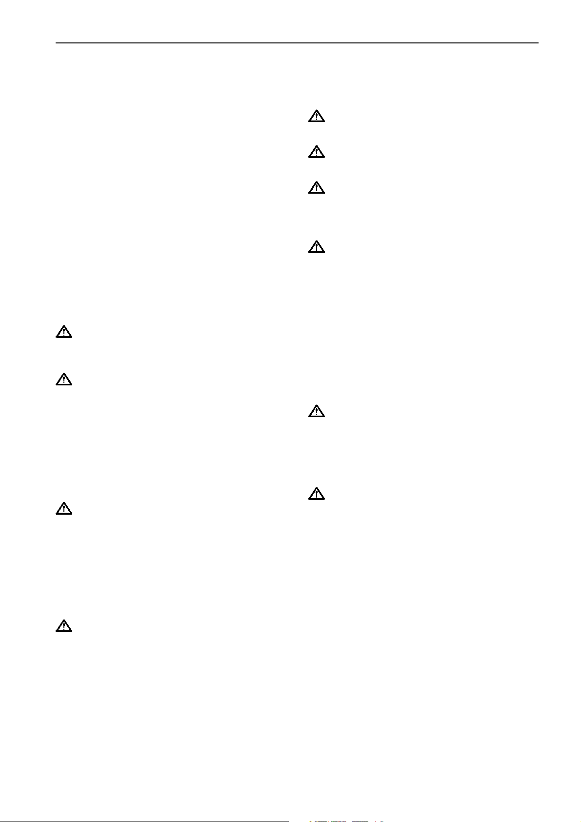
Special tools
3838620 3838621 3838622
383 8619
9999324
9998482
383 8619 VODIA complete diagnostic tool.*
Components:
3838620 VODIA – palmtop computer (PDA) with SD card.
3838621 VODIA – docking station. Used with VODIA PDA
(3838620).
3838622 VODIA – cable with connector. Used with dock-
ing station (3838621) on the engine’s communication connector.
*Note. More detailed information about using the VODIA tool can
be found in the tool’s instruction manual.
885675
9812519
888900169998699
885675 Adapter cable for sensor test
9812519 Multimeter
999 9324 Terminal crimping tool
9998482 Gauge for connector on control unit
9998699 Measurebox
88890016 Adapter cable
7

EMS 2 - “Engine Management System” Group 30: Electrical system
EMS 2 - “Engine Management System”
General information
EMS 2 is an electronic system with CAN communication (Controller Area Network) for diesel engine control. The
system has been developed by Volvo and includes fuel control and diagnostic function.
The system consists of a control module, six injectors, a number of sensors that supply the control module with
measurements, sockets for diagnosis and functional checks. The engine can be connected to a communications
interface consisting of a CAN link and a serial link.
CAN - Controller Area Network
The J1939 CAN link is responsible after all communication between the engine control unit (EMS 2) and a
communication interface (such as CIU/DCU), except
for diagnostics. Diagnostics are managed by the socalled J1708/J1587 link. The CAN link is much faster
than the J1708/J1587 link and has been designed to
connect to other components that support the SAE
J1939 protocol, such as instrument panels and transmissions.
If a fault develops on the CAN link, signals for the engine speed potentiometer, and the start and stop
knobs are taken over by the J1708/J1587 link. However, instrument and indicator lamps are completely
turned off.
If faults occur in both links, the engine starts to idle.
The only way to shut off the engine in this case is to
use the auxiliary stop (AUX-STOP).
8
Group 30: Electrical system EMS 2 - “Engine Management System”
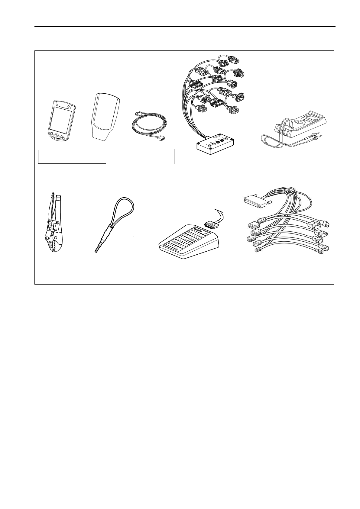
CIU - Control Interface Unit
The CIU is a “translator” between the CAN bus and
the customer’s own control panel. This unit has two
serial communication links, one fast and one slow.
The fast one is a CAN link that features a bus speed
of 250 Kbit/s. All data regarding instruments, indicator
lamps, contacts and potentiometers are controlled by
this bus.
The slower J1708/J1587 link handles diagnostic information for, among other things, the flashing code. The
VODIA diagnosis tool also uses the J1708/J1587 link
to communicate with the system.
DCU - Display Control Unit
DCU is a digital instrument panel that communicates
with the engine control module via the CAN link. DCU
has several functions, such as:
Engine control
– Start, stop, speed control, preheating etc.
Monitoring
– Engine speed, boost pressure, boost temperature,
coolant temperature, oil pressure, oil temperature,
engine hours, battery voltage, instantaneous fuel
consumption and fuel consumption (trip fuel).
Diagnostics
– Shows fault codes in text. Lists previous faults.
Parameter setting
– Idling speed, alarm limit for oil temperature/cool-
ant temperature, droop.
– Preheating for ignition.
Information
– Information about hardware, software and engine
identification.
9

EMS 2 - “Engine Management System” Group 30: Electrical system
Fuel control
The amount of fuel injected into the engine and the injection advance are fully electronically controlled, via
fuel valves in the injectors, once the control unit has
analyzed the engine’s fuel requirements.
This means that the engine always receives the correct volume of fuel in all operating conditions, which
offers lower fuel consumption, minimal exhaust emissions etc.
The control unit monitors and reads the injectors to
ensure that the correct volume of fuel is injected into
each cylinder, and it calculates and set the injection
advance. Control is mainly done with the help of the
speed sensors, fuel pressure sensor and the combined sensor for boost pressure/boost temperature.
The control unit controls the injectors via a signal to
the electromagnetically operated fuel valve in each injector, which can be opened and closed.
Calculation of fuel quantity
The quantity of fuel to be injected into the cylinder is
calculated by the control unit. The calculation determines the time that the fuel valve is open (when the
fuel valve is open fuel is sprayed into the cylinder).
The parameters which govern the amount of fuel injected are:
• Demanded engine speed
• Engine protector functions
• Temperature
• Boost pressure
Altitude correction
The control unit contains an atmospheric pressure
sensor and an altitude compensation function for engines that operate at high altitude. This function limits
the fuel volume in relation to ambient air pressure.
This is to prevent smoke, high exhaust temperature
and to protect the turbocharger from overspeeding.
Diagnostic function
The task of the diagnostic function is to discover and
localize any malfunctions in the EMS 2 system, to
protect the engine and to inform about any problems
that occur.
If a malfunction is discovered, this is announced by
warning lamps, a flashing diagnostic lamp or in plain language on the instrument panel, depending on the equipment used. If a fault code is obtained as a flashing code
or in plain language, this is used for guidance in any fault
tracing. Fault codes can also be read by Volvo’s VODIA
tool at authorized Volvo Penta workshops.
In case of serious disturbances, the engine is shut
down completely or the control module decreases the
power output (depending on the application). Once
again, a fault code is set for guidance in any fault
tracing.
10
Group 30: Electrical system Component location
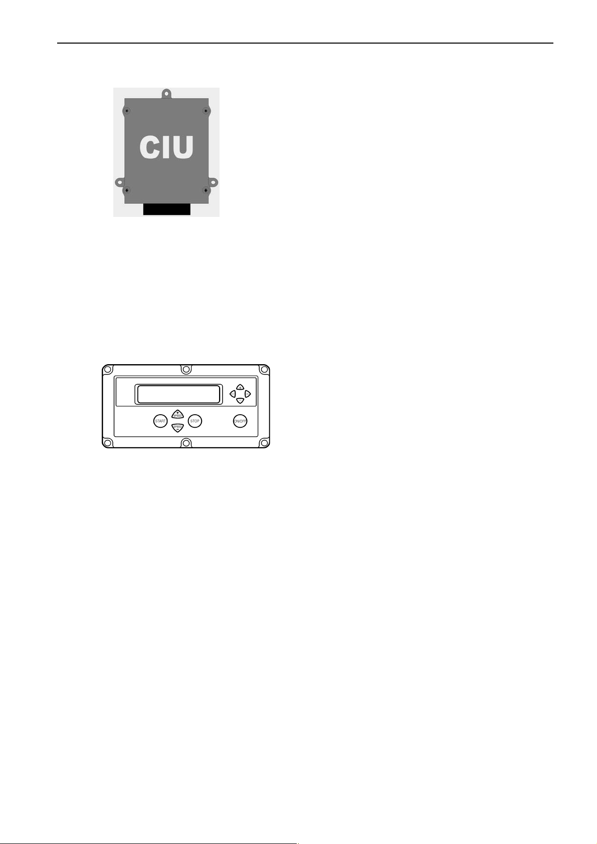
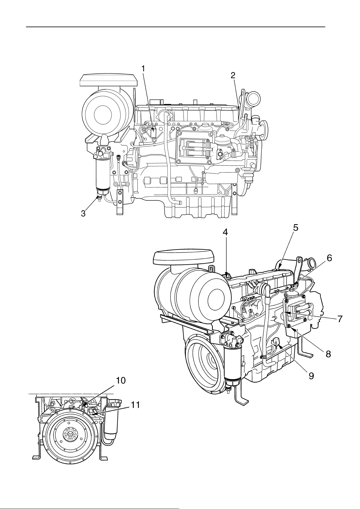
Component location TAD 650, 660, 750, 760 VE
NOTE! Location can differ, depending on engine model.
2
1
1. Speed sensor, camshaft
2. Connection, EMS 2
3. Solenoid controlled proportional valve, high pressure pump – fuel (MPROP)
4. Fuel pressure
5. Fuel pressure in comman rail
6. Glow plugs, one for each injector
7. Oil pressure sensor
8. Boost pressure and temperature
9. Solenoid valve, EGR
10. Coolant temperature
11. Speed sensor, crankshaft
12. Water in fuel (not shown, mounted on primary
fuel filter).
3
4
5
6
7
8
11
9
10
11
Component description Group 30: Electrical system
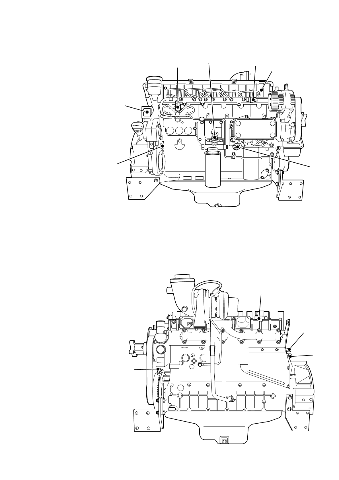
Component location TAD 734 GE
1. Solenoid controlled proportional valve,
high pressure pump – fuel (MPROP)
2. Coolant temperature sensor
3. Water in fuel switch(mounted on primary
fuel filter).
4. Boost pressure and temperature sensor
5. Preheater, intake manifold
6. Fuel pressure in comman rail
7. Fuel pressure sensor
8. Oil pressure sensor
9. Main relay
10. Speed sensor, crankshaft
11. Speed sensor, camshaft
12
Group 30: Electrical system Component description
Component description
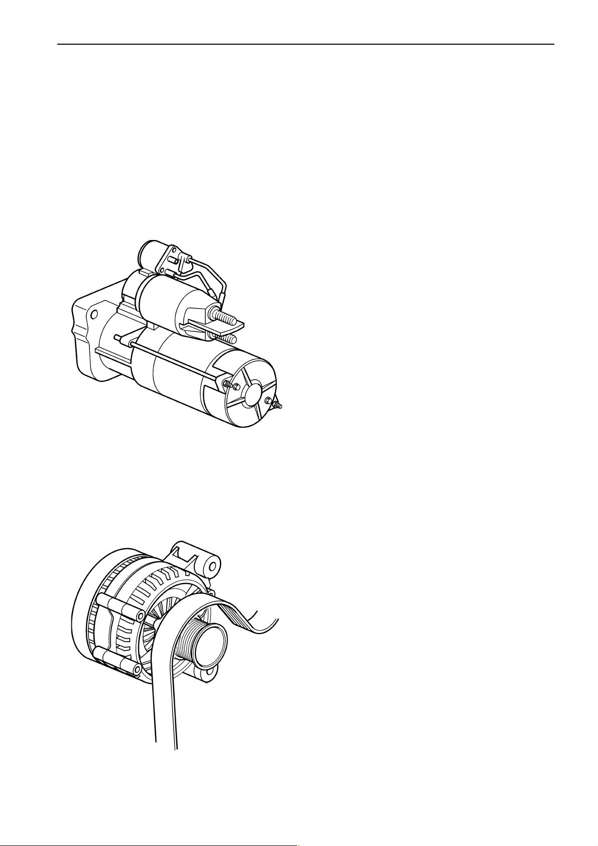
Starter motor
The starter motor is installed in the flywheel housing,
on the left-hand side of the engine. The starter motor
relay is “positive connected”, which means that the relay is connected to battery voltage.
Alternator
The alternator is belt driven and mounted on the front
of the engine, on the right.
13
Component description Group 30: Electrical system
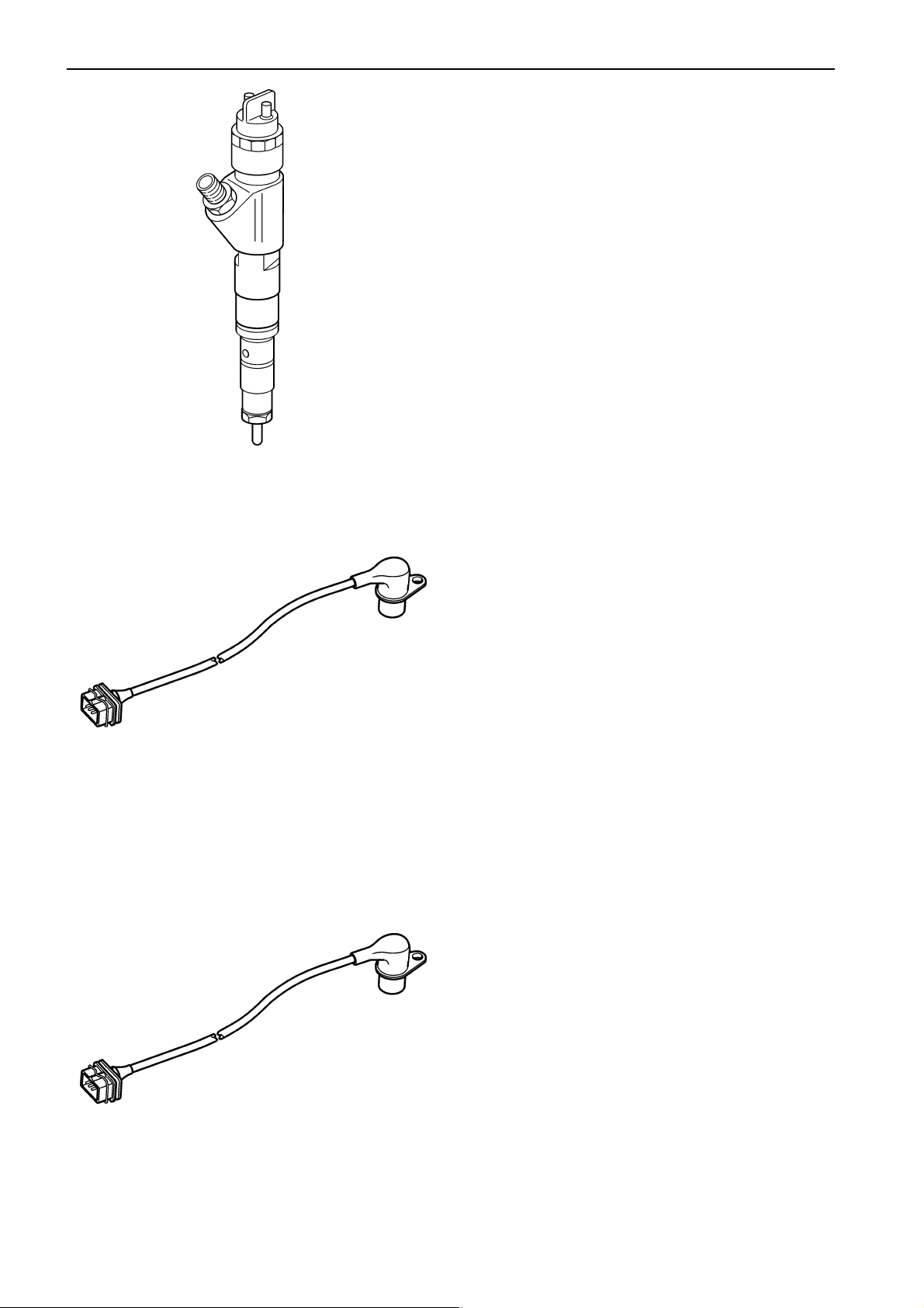
Injectors
The injectors are installed on the cylinder head.
The amount of fuel injected and injection duration is
controlled by the engine control unit, via electromagnetically controlled fuel valves in the injectors. This
means that the engine always receives the correct
volume of fuel in all operating conditions, which offers
lower fuel consumption, minimal exhaust emissions
etc.
Speed sensor, crankshaft
The engine speed sensor is an inductive sensor.
When the crankshaft rotates impulses are created in
the sensor via a tooth wheel on or behind the torsion
damper. The impulses create a pulse signal in the
sensor that the engine control unit (EMS 2) uses to
calculate the crankshaft’s rpm.
The tooth wheel has a tooth free gap for the EMS 2 to
recognize the crankshafts position.
The signal is sent to the engine control unit, which
calculates the injection in advance and the amount of
fuel to be injected.
Speed sensor, camshaft (camshaft position)
The camshaft sensor is an inductive sensor. When
the camshaft rotates impulses are created in the sensor via a tooth wheel installed on the camshaft. The
tooth has seven teeth, one for each cylinder and one
to determine when cylinder one is to be injected. The
impulses create a pulse signal in the sensor that the
engine control unit (EMS 2) uses to calculate when a
cylinder is in turn for injection.
14
Group 30: Electrical system Component description
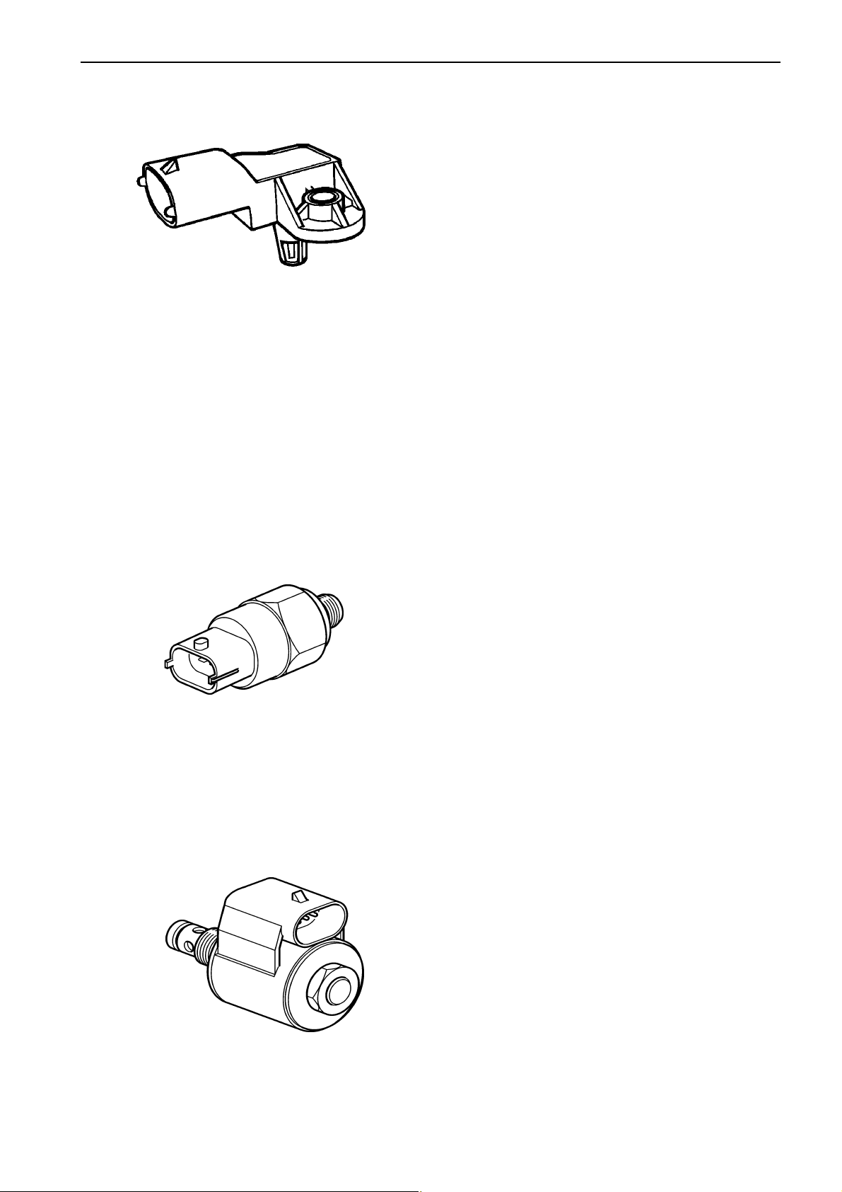
Sensor, boost pressure/ boost
temperature
The boost pressure and the boost temperature are
measured by a combined sensor located on the inlet
manifold on the left of the engine.
The sensor is supplied by a 5 Volt reference voltage
from the engine control module.
The boost pressure sensor measures the absolute
pressure, which is the sum of the boost pressure and
atmospheric pressure (300 kPa thus corresponds to a
boost pressure of 200 kPa when atmospheric pressure is 100 kPa).
The pressure signal is a voltage signal which is proportional to absolute pressure.
The boost temperature sensor consists of a non-linear resistor, whose resistance varies with boost temperature. The resistance falls as the temperature rises.
Sensor, oil pressure, engine
Oil pressure is measured by a sensor installed in the
engine block on the right side of the engine.
The sensor measures pressure in the main oil gallery,
and is supplied by a 5 Volt reference voltage from the
engine control module.
The pressure signal is a voltage signal which is proportional to the lubrication oil pressure.
IEGR (only VE engines)
The IEGR valve is a 2-way solenoid valve controlled by
the engine control unit. The IEGR solenoid controls a
oil pressure that effects a control valve which activate
the exhaust gas recirculation function.
15
Component description Group 30: Electrical system
Coolant temperature sensor
The sensor is located on the cylinder head, at the rear
end of the engine.
The sensor senses the engine coolant temperature
and sends the information to the engine control unit.
The sensor consists of a non-linear resistor, whose resistance varies with coolant temperature. The resistance falls as the coolant temperature rises.
Sensor, common rail pressure
(fuel)
The sensor is mounted on the right of the engine, at
the front of the common rail, which distributes fuel to
the injectors.
The rail pressure sensor senses the fuel pressure and
converts this to a voltage which is registered by the
engine control unit.
16
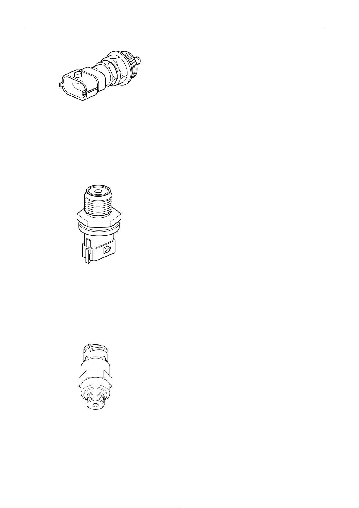
Sensor, fuel pressure
The sensor measures fuel pressure and is located on
the fuel filter bracket. The sensor is an active sensor,
i.e. the sensor requires a supply voltage of +5 Volt.
The sensor provides an output signal whose voltage is
proportional to the pressure that the sensor measures.
Group 30: Electrical system Component description
Magnetically controlled proportional valve (MPROP)
A magnetically controlled proportional valve (MPROP)
controls the high pressure pump to ensure that the
correct fuel pressure (rail pressure) is retained despite
varying engine speed and loading.
The input signal to the valve is a PWM signal whose
pulse width is controlled by the engine control module.
When the current through the valve is changed, this affects the fuel flow, which results in changed rail pressure.
Water in fuel switch, secondary
fuel filter
A switch is located in the water trap under the fuel filter. Its task is to detect whether there is water in the
fuel.
The switch senses the resistance between two pins,
wich are in contact with the fuel. When there is no water in the fuel, the resistance is very high. If there is
any water in the fuel, the resistance falls.
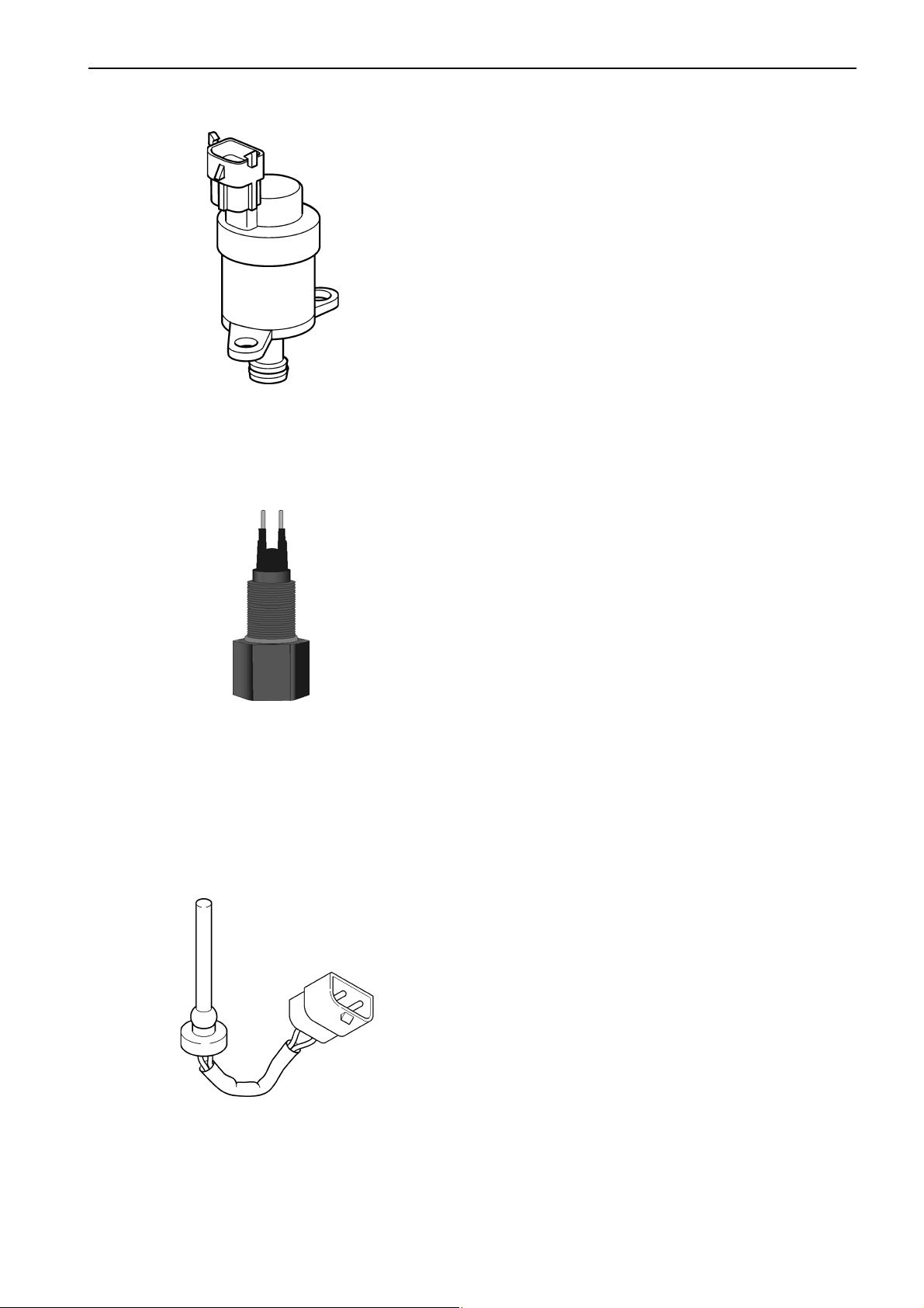
Switch, coolant level
The task of the switch is to discover whether the coolant level in the engine (expansion tank) has become
too low. An alarm signal is sent when the coolant level
is too low.
17

Component description Group 30: Electrical system
Preheater with preheater relay
The preheater is located in the inlet manifold at the left
side of the engine. The preheat relay is located at the
engines left side beneath the preheater.
Engine control unit, EMS 2
The engine control unit checks and controls the injectors, to ensure that the correct volume of fuel is injected into each cylinder at the right time. It also controls
the high pressure pump via the proportional valve
(MPROP) to ensure that the system always has the
correct fuel pressure (rail pressure).
The control unit also calculates and adjusts the injection advance. Regulation is mainly done with the aid of
the engine speed sensor and the combined sensor for
boost pressure/boost temperature.
The EMS 2 system processor is located in the control
unit, protected from water and vibration.
The processor receives continuous information about:
Engine speed
•
Throttle
•
Oil pressure
•
Boost pressure /temperature
•
Fuel pressure (common rail pressure)
•
Fuel alarm, “water in fuel”
•
Camshaft position
•
Coolant temperature
•
18
The information provides information about current operation conditions and allows the processor to calculate
the correct fuel volume, monitor engine status etc.

Group 30: Electrical system Repair instructions
Repair instructions
General advice on working
with EMS engines
The following advice must be followed to avoid
damage to the engine control unit and other electronics.
IMPORTANT! The system must be disconnect-
ed from system voltage (by cutting the current
with the main switch) and the starter key(s) must
be in the 0 position when the engine control
module connectors are disconnected or connected.
● Never disconnect the current with the main
switches when an engine is running.
● Never undo a battery cable when the engine is
running.
● Turn the main switches off or disconnect the bat-
tery cables during quick charging of the batteries.
● NOTE! During normal trickle charging, it is not
necessary to turn the main switches off.
● Only batteries may be used for start help. A help
start device can produce a very high voltage and
damage the control unit and other electronics.
● If a connector is disconnected from a sensor, be
very careful to avoid allowing the contact pins to
come into contact with oil, water or dirt.
19
Repair instructions Group 30: Electrical system
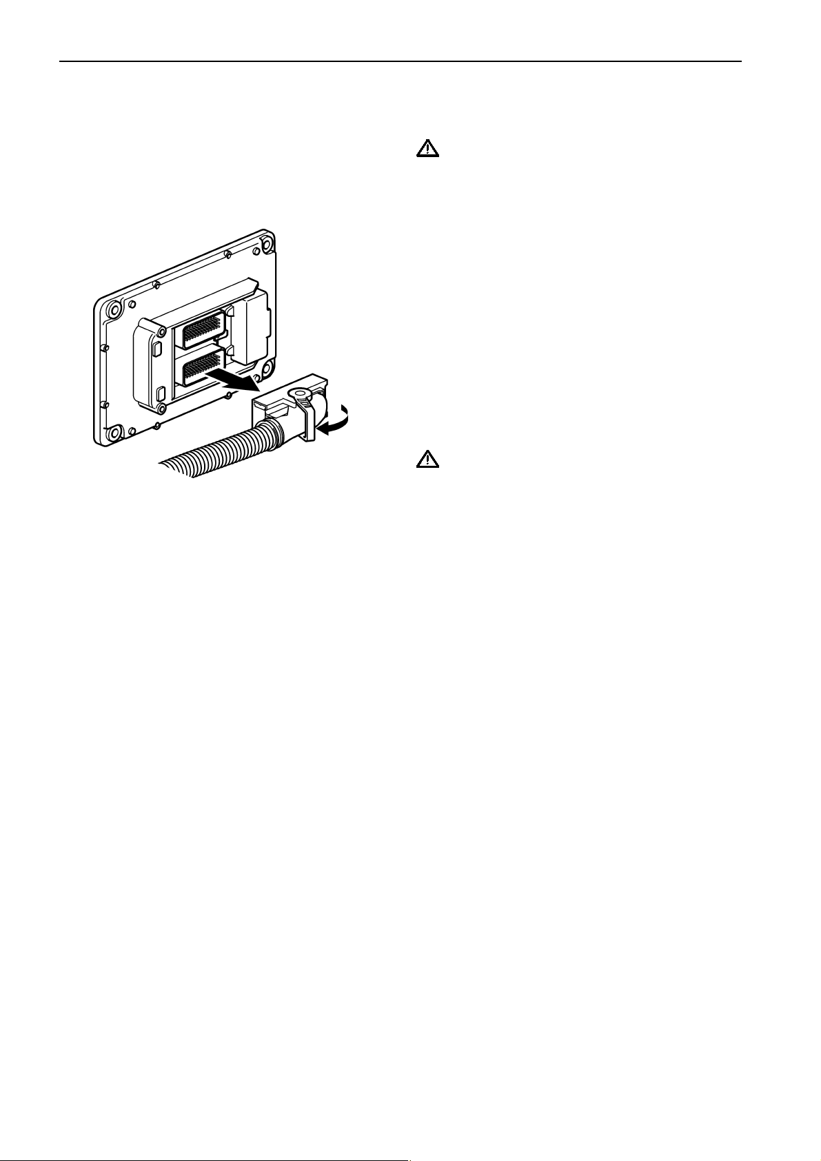
Electric welding
1. NOTE! Cut the current with the main switch.
IMPORTANT! The system must be disconnect-
ed from system voltage when the engine control
module connectors are disconnected or connected.
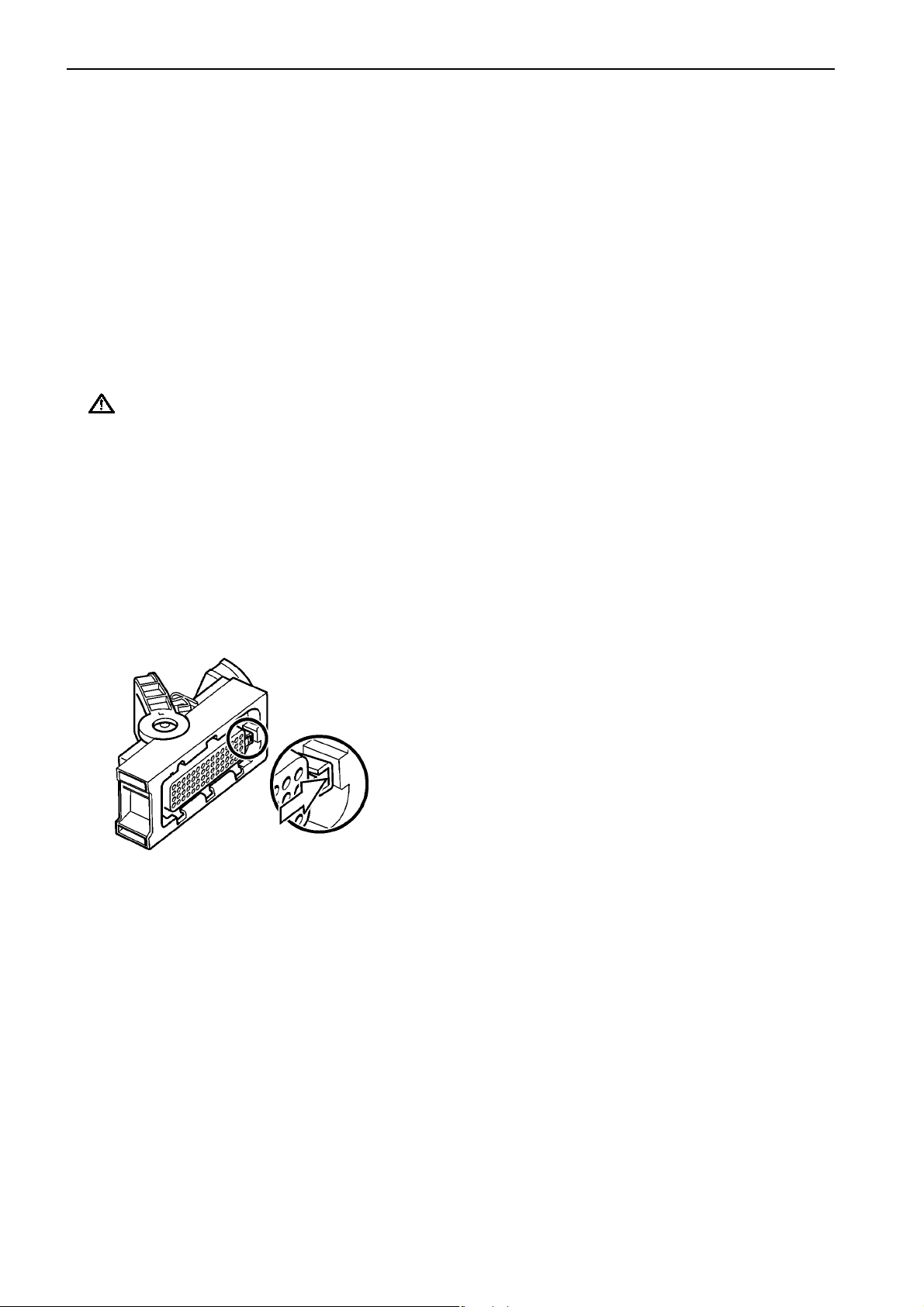
2. Undo the two connectors from the engine control
unit before any electric welding starts. Turn the
locking arm down at the same time as the connector is pulled outwards.
3. Disconnect all connections to the alternator.
Connect the welder earth clamp to the component
to be welded, or as close as possible to the weld
site. The clamp must never be connected to the
engine or in such a way that current can pass
through a bearing.
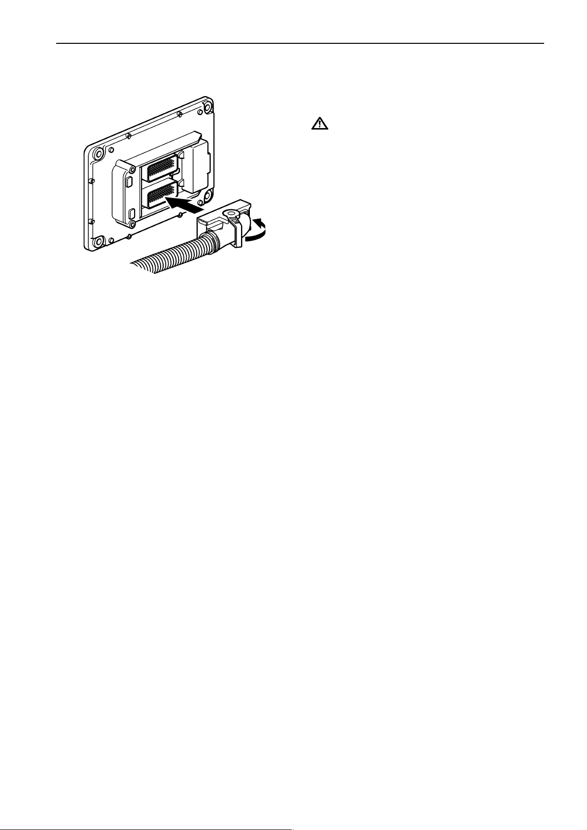
IMPORTANT! After welding is completed, the
disconnected components, such as alternator
cables and battery cables must be connected in
the correct order.
The battery cables must always be connected
last.
20
Group 30: Electrical system Repair instructions
Changing the engine control
unit
1. NOTE! Cut the current with the main switch.
IMPORTANT! The system must be disconnect-
ed from system voltage when the engine control
module connectors are disconnected or connected*.
2. Remove the two connectors from the engine control unit. Turn the locking arm down at the same
time as the connector is pulled outwards
3. If the new engine control unit has recently been
programmed:
Start the engine and check whether any fault
codes related to the engine control unit occur.
21
Repair instructions Group 30: Electrical system
Reprogramming a control unit
IMPORTANT! The CHASSIS ID number must
be readily available to allow the software to be
downloaded.
Action:
1. Log in to Volvo Penta Partner Network’s website:
www.vppn.com
2. Choose “VODIA” in the left-hand menu.
3. Choose “ECU programming” in the left-hand
menu.
4. Follow the instructions under “Download software”. Choose the control units to be reprogrammed and click the “Download” button. The
software for the control units is now downloaded
to the PDA*.
* Note. PDA = “Personal Digital Assistant” (palmtop computer).
5. Take a look under “Settings”, “Software information” in VODIA to check that the software has
been downloaded.
8. The next control unit is the vehicle ECU.
Select “Electrical system and instruments” in the
VODIA menu.
Select “MID 144 ECU, programming”.
VODIA will guide you through the entire programming process.
9. NOTE! Programming must be reported back to
Volvo Penta within 28 days. Log in to Volvo Pen-
ta Partner Network’s web site:
www.vppn.com
10. Choose “VODIA” in the left-hand menu.
11. Choose “Report software” in the left-hand menu.
12. Follow the instructions for “Report software/parameter”. Click “Report software/parameter”.
6. Connect the VODIA to the engine (control unit) to
be programmed.
7. Start with the engine control unit.
Select “Engine with mounting and equipment” in
the VODIA menu.
Select “MID 128 Control unit, programming”.
VODIA will guide you through the entire programming process.
22

Group 30: Electrical system Repair instructions
Programming an empty
control unit
When a new engine control unit is installed, where no
software has been downloaded, the control unit must
be programmed.
The new control unit must have the same part number
as the old control unit. If the control units do not have
the same part number, it will not be possible to program the new control unit until a “Conversion kit” has
been ordered from Volvo Penta.
If the control units have the same part number, the
new control unit can be programmed as usual. Please
refer to “Programming a control unit”.
If the part numbers do not coincide – proceed as possible:
1. Have both part numbers available.
2. Log in to Volvo Penta Network’s web site:
www.vppn.com
3. Choose “VODIA” in the left-hand menu.
4. Choose “Conversion kit” in the left-hand menu. A
new page, “Conversion kit / Accessory kit”, opens
up.
5. Click the text “Available conversions kits” which
is shown in bold face.
6. A new window opens. Follow the instructions given in the window.
7. Return to the “Conversion kit / Accessory kit”
page and follow the instructions to order a new
“conversion kit”.
8. Volvo Penta’s database is now updated. It can
take about a minute before a confirmation is sent.
9. Programing of the control unit can now start.
Please refer to “Programming a control unit”.
23
Repair instructions Group 30: Electrical system
Fault tracing of cables and
connectors
Special tools: 9812519, 9998482
Check all connectors visually
Check the following:
l Look for oxidation which can impair contact in con-
nectors.
l Check that terminals are undamaged, that they are
correctly inserted into their connectors, and that
the cable is correctly terminated in the terminal.
● Check that there is good mechanical contact in the
connector. Use a loose pin to check this.
IMPORTANT! The multi-pin connectors for
the engine control unit must only be checked
with gauge 9998482.
● Carefully insert gauge 999 8482 into the multi-pin
connector. Pull and push the connector in and out
a few times and feel whether the terminal socket
grasps the tool. If the terminal socket does not
grasp, or if it feels slack, the connection pins
should be changed. Please refer to ”Joining electrical cables for multi-connector” Check the secondary locking in the connector.
Contact problems
Intermittent contact or temporary recurring faults can
be difficult to fault trace, and are frequently caused by
oxidation, vibration or poorly terminated cables.
Wear can also cause faults. For this reason, avoid disconnecting a connector unless it is necessary.
Other contact problems can be caused by damage to
pins, sockets and connectors etc.
Shake cables and pull connectors during measurement, to find where the cable is damaged.
Contact resistance and oxidation
Resistance in connectors, cables and junctions
should be close to 0 Ω. A certain amount of resistance
will occur, however, because of oxidation in connectors.
If this resistance is too great, malfunctions occur. The
amount of resistance that can be tolerated before malfunctions occur varies, depending on the load in the
circuit.
Open circuit
● If possible, shake the cables and pull the connec-
tors during measurement to discover whether the
cable harness is damaged.
● Check that the cables are not damaged. Avoid
clamping cables in tight bends close to the connector.
● Check the function of the secondary locking.
Possible reasons for faults could be chafed or broken
cables, or connectors which have come undone.
Use the wiring schedule to check the cable harnesses
which are relevant to the function. Start off with the
most probable cable harness in the circuit.
Check the following:
● Disconnect the relevant connector at each end of
the cable harness.
● Use multimeter 9812519 to measure the resis-
tance between the ends of the cable.
Nominal value close to 0 Ω.
● If possible, shake the cables and pull the connec-
tors during measurement to discover whether the
cable harness is damaged.
● Check the next cable harness in the wiring sched-
ule if no fault has been found.
24
Group 30: Electrical system Repair instructions
Joining electrical cables for
connectors
Special tools: 9808648, 999 9324
Repair kit: 1078054
1
Disconnect the connector from the engine control unit
or from the power supply unit, please refer to ”Control
unit, changing”.
Undo the connector, to gain access to the cable leading to the pin which is to be changed.
2
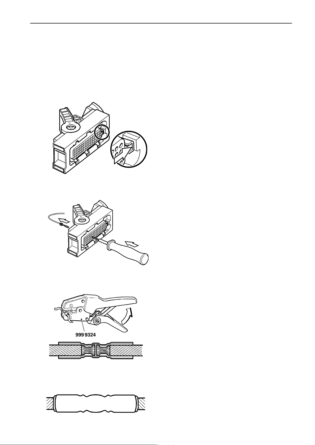
Undo the pin catch.
3
Remove the pin with tool no. 9808648.
NOTE! Only remove one pin at a time.
4
Cut off the cable and the pin which is to be changed.
Join the cable with the new one, using repair kit
10.78054. Use cable crimping tool no. 999 9324.
5
Carefully heat the joint with a hot air gun, to make the
insulation shrink and seal tightly.
25

Repair instructions Group 30: Electrical system
6
Put the pin back in the right place in the connector before removing the next pin, if several pins are to be
changed. Check that the locking tongue locks the pin
in the connector.
7
Install the cables with insulation and tie wraps in the
connector, in the reverse order to disassembly.
8
Install the connector in the reverse order to disassembly.
9
Check that the connector and the mating connector on
the engine control unit or power supply unit are clean
and dry.
10
Join up the multi-pin connector. Please refer to ”Control unit, changing” for advice on joining up the connector.
11
Start the engine and check carefully that no fault
codes occur.
Checking the starter motor
voltage
Special tools: Multimeter 981 2519
General
If battery voltage falls below 24.7 V*, the starter motor
will not be able to crank the engine at normal speed.
A fully charged battery has an open circuit voltage of
about 25.4 V.
* Note. Measured on the batteries.
Voltage measurement, check
1
Check that the battery voltage is at least 24.7 V* when
unloaded by using multimeter 9812519 to measure
between the battery poles.
* Note. Measured on the batteries.
26
2
Turn the main switch on.
3
Check that the voltage between terminal B+ on the starter motor and battery negatives connection point is the
same as the battery voltage.

Group 30: Electrical system Repair instructions
Checking the charging system
Special tools: 9812519
Generally about alternators:
The voltage output from an alternator must be limited
to prevent the elecrolyte in the battery to evaporate.
The alternator output is regulated (limited) by the voltage regulator in the alternator. The maximum current
that the alternator can deliver at regulated voltage output depends on the alternator revolution. When the engine is started an excitation current is needed to
“wake up” the alternator.
NOTE! It is the consumers (batteries included) which
decides the output current from the alternator.
Measurements
1. Engine off.
2. Use multimeter 9812519 to do a voltage measurement over the battery. The nominal voltage over a
full loaded battery is approx. 25.4V.
3. Engine on. Run at 1500 rpm.
4. Use multimeter 9812519 to do a voltage measurement over the battery. The nominal charging voltage over the battery should be approx. 27.8-
28.6V.
Fault tracing charging system
Battery
1. Check that all connectors at the battery is correct
assembled.
2. Check the conditions of the cables to the battery.
3. Check the water level in the battery.
4. Check, if possible, the specific gravity of all cells.
when no charge
1. Check the alternator belt tension.
2. Check that all connectors at the alternator and at
the battery is correct assembled.
3. Check the conditions of all cables in the charging
system.
4. Regulator fault, try another alternator.
when undercharge
1. Check the alternator belt tension.
2. Check that all connectors at the alternator and at
the battery is correct assembled.
3. Check the conditions of all cables in the charging
system.
4. Regulator fault, try another alternator.
when overcharge
1. Probably regulator fault, try another alternator.
27
Repair instructions Group 30: Electrical system
Rail pressure measurement
This measurement is used for measuring the rail pressure. For example if the engine doesn’t start this measurement can show the rail pressure while the engine
is cranking. If it is air in the system the rail pressure
could be too low for the engine control unit to activate
injection.
1. NOTE! Starter key in position 0.
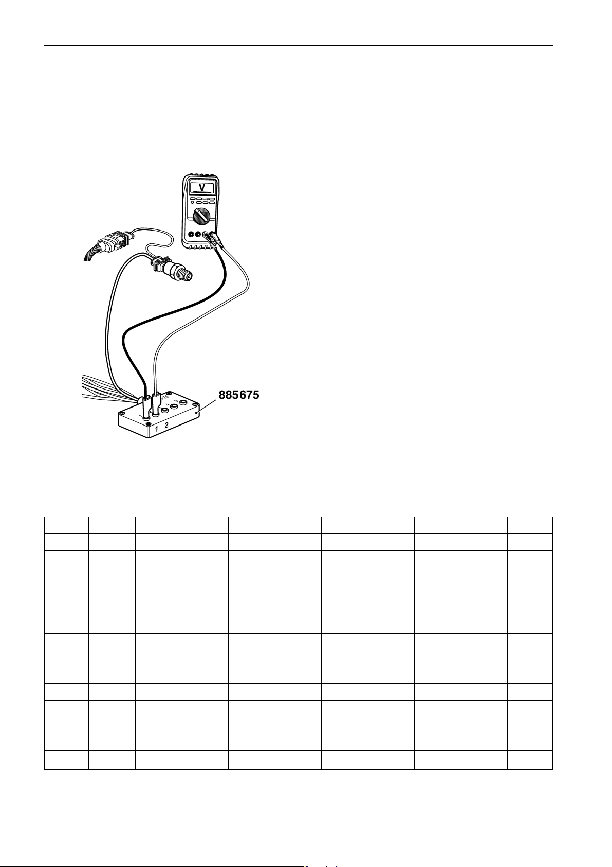
2. Undo the connector from the sensor.
3. Connect adapter cable (885675) between the sensor and the engine control unit.
4. Use multimeter (9812519) for voltage measurement. Connect the COM from the multimeter to
measurement point 1. Connect V from the multimeter to measurement point 2.
5. NOTE! Starter key in position I. The multimeter
should now show 0.5 Volt which is equal to 0Mpa
(0bar).
6. When cranking the engine, read the voltage value
on the multimeter and look in the table which pressure the voltage equals.
NOTE! To activate injection a rail pressure of at least
25 MPa (250 bar) is demanded.
Voltage 0.5 0.95 1.0 1.1 1.2 1.3 1.4 1.5 1.6 1.7
MPa 0 20.3 22.5 27.0 31.5 36.0 40.5 45.0 49.5 54.0
Bar 0 203.0 225.0 270.0 315.0 360.0 405.0 450.0 495.0 540.0
Voltage 1.8 1.9 2.0 2.1 2.2 2.3 2.4 2.5 2.6 2.7
MPa 58.5 63.0 67.5 72.0 76.5 81.0 85.5 90.0 94.5 99.0
Bar 585.0 630.0 675.0 720.0 765.0 810.0 855.0 900.0 945.0 990.0
Voltage 2.8 2.9 3.0 3.1 3.2 3.3 3.4 3.5 3.6 3.7
MPa 103.5 108.0 112.5 117.0 121.5 126.0 130.5 135.0 139.5 144.0
Bar 1035.0 1080.0 1125.0 1170.0 1215.0 1260.0 1305.0 1350.0 1395.0 1440.0
Voltage 3.8 3.9 4.0 4.1 4.2 4.3 4.4 4.5
MPa 148.5 153.0 157.5 162.0 166.5 171.0 175.5 180.0
Bar 1485.0 1530.0 1575.0 1620.0 1665.0 1710.0 1755.0 1800.0
28

Group 30: Electrical system Malfunctions
Malfunctions
Fault code information
• MID - Message Identification Description:
The MID consists of a number which designates
the control unit that sent the fault code message.
(e.g. the engine control unit).
• PID - Parameter Identification Description:
The PID consists of a number that designates a
parameter (value) to which the fault code relates
(oil pressure, for example).
• PPID - Proprietary PID:
The same as the PID, but this is a Volvo-specific
parameter.
• SID - Subsystem Identification Description:
The SID consists of a number that designates a
component to which the fault code relates
(injector, for example).
• PSID - Proprietary SID:
The same as the SID, but this is a Volvo-specific
component.
• FMI - Failure Mode Identifier:
FMI indicates the type of fault (please refer to the
FMI table below).
• SPN - Suspect Parameter Number
29

Malfunctions Group 30: Electrical system
FMI table
SAE standard
FMI Display text SAE text
0 “Value too high” Valid data, but above the normal working range
1 “Value too low” Valid data, but below the normal working range
2 “Faulty data” Intermittent or faulty data
3 “Electrical fault” Abnormally high voltage or short circuit to higher voltage
4 “Electrical fault” Abnormally low voltage or short circuit to lower voltage
5 “Electrical fault” Abnormally low current or open circuit
6 “Electrical fault” Abnormally high current or short circuit to battery negative
7 “Mechanical fault” Faulty response from mechanical system
8 “Mechanical or electrical fault” Abnormal frequency
9 “Communication fault” Abnormal updating rate
10 “Mechanical or electrical fault” Abnormally large variations
11 “Unknown fault” Unidentified fault
12 “Component fault” Faulty unit or component
13 “Faulty calibration” Calibration values outside the limits
14 “Unknown fault” Special instructions
15 Data valid but above normal operating range - least severe level
16 Data valid but above normal operating range - moderately severe level
17 Data valid but above normal operating range - least severe level
18 Data valid but above normal operating range - moderately severe level
19 Received network data in error
20 Reserved for SAE assignment
21 Reserved for SAE assignment
22 Reserved for SAE assignment
23 Reserved for SAE assignment
24 Reserved for SAE assignment
25 Reserved for SAE assignment
26 Reserved for SAE assignment
27 Reserved for SAE assignment
28 Reserved for SAE assignment
29 Reserved for SAE assignment
30 Reserved for SAE assignment
31 Condition exist
30

Group 30: Electrical system Malfunctions
Volvo-specific for injectors
(MID 128, SID 1–6)
FMI Help
3 Short circuit to battery voltage, injector low voltage side
4 Short circuit to battery negative, injector low voltage or high voltage side
5 Open circuit in injector circuit
7 Mechanical system not responding properly
12 Low injector hold current
General advice
NOTE!
The following must be done before fault tracing continues, to avoid changing functional
sensors:
● If there is an active/inactive fault code.
Remove the connector from the sensor. Check
that there is no oxidation and that the connector
pins are not damaged.
If there is a fault, please refer to the instructions
in chapter “Fault tracing of cables and connectors”.
NOTE! Some fault codes become inactive when the
engine is stopped. Start the engine to check whether
the fault code is still inactive with the engine running.
● After an action with the connector
Put the connector* back. Check if the fault code
becomes inactive.
Check faults that could be related to that specific sensor.
If the fault remains, measure the cables and
sensors to check them, as instructed.
*NOTE! No grease in the connector.
31

Malfunctions Group 30: Electrical system
Network
The system has two types of communication buses.
CAN
A data link (CAN bus) links the nodes to each other.
CAN (“Controller Area Network”) is an industrial standard for distributed systems.
The CAN bus consists of a pair of copper conductors
which are twisted 30 times per meter. The nodes communicate via the CAN bus and they form a network together, which exchanges information and benefits
from each other’s services.
The CAN bus is a serial bus and is the primary control
bus.
J1587
The communication bus, J1587, is also used for accessories and for diagnostics.
This is a serial bus in accordance with standard SAE
J1708.
32

Group 30: Electrical system Malfunctions
Manual fault tracing in bus
cables
Special tools:
Multimeter ..................................................... 9812519
IMPORTANT! Cut the current with the main
switch before the cables are disconnected.
Use the multimeter to check the bus cables. The conductors in the bus cables should not be in contact
with each other.
Disconnect a bus cable at each end and measure the
resistance between the pins to check this. The multimeter should show infinite resistance between each
pin. If the resistance is less than infinite, there is a
fault.
Measuring the engine cables
Two types of measurement are done on the engine
cable harness, both resistance measurement and voltage measurement.
The measurements are done to ensure that no open
circuits or short circuits occur.
If there is an open circuit, the resistance is infinite,
and if there is a short circuit, it is close to zero. The
resistance values given in the workshop manual are
approximate, and should be regarded as guidelines.
NOTE!
When resistance measurement is done, the engine
should be stopped and system voltage should be
cut off with the main switch.
All resistance measurement is done at +20°C
(68°F) and with a cold engine.
33

Diagnostic Trouble Codes Group 30: Electrical system
Diagnostic Trouble Codes
MID 128, PID 45
Inlet air heater status
MID 128: Engine control unit
FMI 3: The voltage exceeds the normal value or is
short circuited to higher voltage.
FMI 4: The voltage is less than the normal value or
is short circuited to lower voltage.
FMI 5: The current is less than the normal value or
is open circuited.
FMI Fault code explanation
3, 4, 5 Faulty sensor / Faulty sensor circuit
Fault indication
DCU: Engine warning in DCU display.
CIU: Flash code
Flash code
Electrical fault: 5.4
Value fault: None
Symptom
FMI 3, 5: Preheat relay never activated. White
smoke for cold start. Start problems in
cold climate.
FMI 4: Induction air is hot. Preheat relay is im-
possible to turn off. Preheat fuse will
break.
34

Group 30: Electrical system Diagnostic Trouble Codes
Circuit description
In cold climate the intake air need too be preheated.
This is either done for GE engines by the preheater
which is located in the inlet manifoldor or for VE engines by the glowplugs that are mounted in the cylin-
pre-heat relay
derhead. The preheat function is activated/deactivated
by the engine control unit via the preheat relay. When
the preheat function is activated B25 alter its potential
and the relay activates. B7 is a sense cable which
senses that the voltage supply to the preheater is correct.
Fault tracing
FMI 3 Abnormally high voltage or short
circuit to higher voltage
Possible reason:
• Short circuit to B+ in cable harness between EMS
2 and preheat relay.
Suitable action:
1. Check cable harness and connectors between
EMS 2 and preheat relay.
FMI 4 Abnormally low voltage or short
circuit to lower voltage
Possible reason:
• Short circuit to battery negative in cable harness
between EMS 2 and preheat relay.
Suitable action:
1. Check cable harness and connectors between
EMS 2 and preheat relay.
35

Diagnostic Trouble Codes Group 30: Electrical system
FMI 5 Abnormally low current or open
circuit
Possible reason:
• An open circuit in cable harness between EMS 2
and preheat relay.
Suitable action:
1. Check the contact pressure in socket 25 in the
engine connector B.
2. Check cable harness and connectors between
EMS 2 and preheat relay.
Measurements
NOTE! If any of the measurements shows an abnor-
mal value, check the wiring to and from the engine
control unit and the preheat relay.
Checking the wiring:
1. NOTE! Cut the current with the main switch.
2. Remove connector B from the EMS 2.
3. Connect the B connector to brakeout cable
9990014 with measurebox 9998699.
4. Use multimeter 9812519 to do a resistance mea-
surement.
Measurement points on box Nominal value
7 (preheat sense) - R ≈ 0 Ω
one of the preheat connectors
25 (relay activation) - R ≈ 0 Ω
one of the preheat connectors
60 (relay +) - R ≈ 0 Ω
one of the preheat connectors
36

Group 30: Electrical system Diagnostic Trouble Codes
MID 128, PID 94
Fuel pressure
MID 128: Engine control unit
FMI 1: The sensor value is valid but below the nor-
mal working range.
FMI 3: The voltage exceeds the normal value or is
short circuited to higher voltage.
FMI 5: The current is less than the normal value or
is open circuited.
FMI 7: Mechanical fault. The system responds in-
correctly.
FMI Fault code explanation
1 Fuel pressure is too low
3, 5 Faulty sensor / Faulty sensor circuit
7 Fuel pressure is critically low
Fault indication
DCU: Engine warning in DCU display.
CIU: Flash code
Flash code
Electrical fault: 3.6
Value fault: 3.8
Symptom
None
Circuit description
splice
splice
engine
interface
Note! Only TAD 650, 660, 750, 760 has an engine interface. On
TAD 734 the wiring to the EMS 2 is the same but without any engine interface.
fuel pressure
The sensor is an active sensor, i.e. the sensor must
receive operating voltage. Pin B17 on the engine control unit provides pin 1 on the sensor with an operating
voltage of +5 Volt. Pin 4 on the sensor is connected to
battery negative via pin B18 on the engine control unit.
The output signal from the pressure sensor, pin 2 on
the sensor to pin B16 on the EMS 2, is a voltage signal that is proportional to the fuel pressure.
37

Diagnostic Trouble Codes Group 30: Electrical system
Fault tracing
FMI 1 Fuel pressure is too low
Conditions for fault code:
The fuel pressure alarm depends on the engine revo-
lution.
Suitable action:
1. Check fuel level.
2. Open all fuel cocks and check that no leakage
occurs.
3. Check drive belt adjustment.
4. Change all fuel filters. (pre- and fine filter)
5. Check that no fuel hose is squeezed or folded.
6. Check function of fuel pressure sensor by control
measuring the fuel pressure. (see workshop manual)
7. Check fuel feed pump.
8. Change fuel pressure release valve. (see workshop manual)
FMI 3 Abnormally high voltage or short
circuit to higher voltage
Conditions for fault code:
The voltage on pin B16 on the EMS 2 is more than
4,75 Volt.
Possible reason:
• An open circuit in fuel sensor negative cable.
• Short circuited fuel sensor signal cable to 5V volt-
age or to battery voltage.
• Faulty sensor.
Suitable action:
1. Check contact pressure in socket 18 in the engine
connector B. Also check contact pressure in connector at fuel pressure sensor.
2. Check cable harness and connectors between fuel
sensor and EMS 2.
3. Check function of fuel pressure sensor.
38

Group 30: Electrical system Diagnostic Trouble Codes
FMI 5 Abnormally low current or open
circuit
Conditions for fault code:
The voltage on pin B16 on the EMS 2 is less than
0.07 Volt.
Possible reason:
• An open circuit in fuel sensor 5V supply cable.
• An open circuit in fuel sensor signal cable.
• Short circuited sensor signal cable to battery neg-
ative.
• Faulty sensor.
Suitable action:
1. Check contact pressure in socket 16 and 17 in
the engine connector B. Also check contact pressure in connector at fuel pressure sensor.
2. Check cable harness and connectors between fuel
sensor and EMS 2.
3. Check function of fuel pressure sensor.
FMI 7 Critically low pressure
Conditions for fault code:
The fuel pressure alarm depends on the engine revolution.
Suitable action:
1. Check fuel level.
2. Open all fuel cocks and check that no leakage occurs.
3. Check drivebelt adjustment.
4. Change all fuel filters. (pre- and fine filter)
5. Chech that no fuel hose is squeezed or folded.
6. Check functionof fuel pressure sensor by control
measuring the fuel pressure. (see workshop manual)
7. Check fuel feed pump.
8. Change fuel pressure release valve. (see workshop
manual)
39

Diagnostic Trouble Codes Group 30: Electrical system
Measurements
NOTE! If any of the measurements shows an abnor-
mal value, check the wiring to and from the engine interface.
Supply cable
• NOTE! Turn ignition off.
• Disconnect the connector from the sensor
• Connect adapter cable 885675 to the cable har-
ness connector to the engine control unit.
• Use multimeter 9812519 for voltage measure-
ment.
• Turn ignition on.
Measurement points Nominal value
1– 4 U ≈ 5V
Negative cable:
• NOTE! Cut the current with the main switch.
• Disconnect the connector from the sensor
• Connect adapter cable 885675 to the cable har-
ness connector to the engine control unit.
• Use multimeter 9812519 to do resistance mea-
surement against the engine control unit.
Measurement points Nominal value
4 – Battery negative R ≈ 0 Ω
The point of connection for battery negative on the engine
40

Group 30: Electrical system Diagnostic Trouble Codes
Signal cable:
• NOTE! Cut the current with the main switch.
• Disconnect the connector from the sensor
• Connect adapter cable 885675 to the cable har-
ness connector to the engine control unit.
• Use multimeter 9812519 to do resistance mea-
surement against the engine control unit.
Measurement points Nominal value
4 – 2 R ≈ 80 - 120 kΩ
NOTE! Measurement is done to eliminate short circuiting or breaks in the cable to the engine control
unit.
41

Diagnostic Trouble Codes Group 30: Electrical system
Checking fuel pressure sensor
• NOTE! Turn ignition off.
• Disconnect the connector from the sensor
• Connect adapter cable 885675 between the sen-
sor and the engine control unit.
• Use multimeter 9812519 for voltage measure-
ment.
• Turn ignition on.
Measurement points Nominal value
4 – 2 U ≈ 0,5 V
(at normal atmospheric pressure)
Output voltage, V
Component specification
Working range: 0 – 7 bar = 0 – 700 kPa
Supply voltage: 5,00 +/- 0,25 VDC
Nominal output voltage at 25 °C and at supply voltage
5,00 VDC:
0,5 VDC at 0 bar = 0 kPa
4,5 VDC at 7 bar = 700 kPa
Fuel pressure, kPa
42

Group 30: Electrical system Diagnostic Trouble Codes
MID 128, PID 97
Water in fuel
MID 128: Engine control unit
FMI 0: The sensor value is valid but above the nor-
mal working range.
FMI 3: The voltage exceeds the normal value or is
short circuited to higher voltage.
FMI 4: The voltage is less than the normal value or
is short circuited to lower voltage.
FMI Fault code explanation
0 Water in fuel
3, 4 Faulty sensor / Faulty monitor circuit
Fault indication
DCU: Engine warning in DCU display
CIU: Flash code
Flash code
Electrical fault: 2.9
Value fault: 2.1
Symptom
None
splice
water in
fuel
Circuit description
A monitor is located in the water trap under the fuel filter. Its task is to detect whether there is water in the
fuel.
The monitor senses the resistance between two pins,
wich are in contact with the fuel. When there is no water in the fuel, the resistance is very high. If there is
any water in the fuel, the resistance falls.
At a threshold resistance (water has been detected),
the monitor’s output signal (yellow cable) to the engine
control unit pin B8 will be pulled down to zero.
43

Diagnostic Trouble Codes Group 30: Electrical system
Fault tracing
FMI 0 Water in fuel
Conditions for fault code:
Water in the fuel trap has been detected.
Suitable action:
1. Empty the water trap.
2. Check function of water in fuel monitor.
FMI 3
Conditions for fault code:
The voltage signal on B8 is too high.
Possible reason:
• The cable connected to B8 is short circuited to
battery voltage.
Suitable action:
1. Check cable harness and connectors between water in fuel monitor and EMS 2.
FMI 4
Conditions for fault code:
The voltage signal on B8 is too low.
Possible reason:
• Short circuit between both cables to the water in
fuel monitor.
• The cable connected to B8 is short circuited to
battery negative.
Suitable action:
1. Check cable harness and connectors between water in fuel monitor and EMS 2.
44

Group 30: Electrical system Diagnostic Trouble Codes
Measurements
Supply cable:
• NOTE! Turn ignition off.
• Disconnect the connector from the monitor
• Use multimeter 9812519 for voltage measurement
• NOTE! Turn ignition on.
Measurement points Nominal value
Yellow conductor – U ≈ Battery voltage x 0.8
Black conductor
Negative cable:
• NOTE! Cut the current with the main switch.
• Disconnect the connector from the monitor
• Use multimeter 9812519 to do resistance mea-
surement against the engine control unit.
Measurement points Nominal value
Black conductor – R ≈ 0 Ω
Battery negative
Checking water in fuel monitor
1. Disconnect the connector to the water in fuel monitor.
2. Use multimeter 9812519 to do a resistance measurement towards the monitor.
Measurement points Nominal value
1 – 2 Monitor immersed R ≈ 0 Ω
in water
1 – 2 Monitor immersed R ≈∞ Ω
in fuel
45

Diagnostic Trouble Codes Group 30: Electrical system
MID 128, PID 100
Oil pressure
MID 128: Engine control unit
FMI 1: The sensor value is valid but below the nor-
mal working range.
FMI 3: The voltage exceeds the normal value or is
short circuited to higher voltage.
FMI 5: The current is less than the normal value or
is open circuited.
FMI Fault code explanation
1 Oil pressure is too low
3, 5 Faulty sensor / Faulty sensor circuit
Fault indication
DCU: Engine warning in DCU display.
CIU: Flash code
Flash code
Electrical fault: 3.1
Value fault: 6.6
Symptom
FMI 1: Power is reduced due to error torque map if
engine protection parameter is activated.
46

Group 30: Electrical system Diagnostic Trouble Codes
Circuit description
The sensor is an active sensor, i.e. the sensor must
splice
splice
Note! Only TAD 650, 660, 750, 760 has an engine interface. On
TAD 734 the wiring to the EMS 2 is the same but without any engine interface.
oil pressure
receive operating voltage. Pin B17 on the engine control unit (EMS 2) provides pin 1 on the sensor with an
operating voltage of +5 Volt. Pin 3 on the sensor is
connected to battery negative via pin B18 on the EMS
2.
The output signal from the pressure sensor, pin 2 on
the sensor to pin B11 on the EMS 2, is a voltage signal that is proportional to the oil pressure (after the oil
filters).
Fault tracing
FMI 1 Oil pressure is too low
Conditions for fault code:
Oil pressure depends on the engine revolution. Oil
pressure exceeds the set value of the engine protection parameter.
Possible reason:
• Too low engine oil level.
• Blocked oil filter.
• Oil leakage.
• Faulty oil pressure sensor.
Suitable action:
1. Check engine oil level and quality of the oil.
2. Change engine oil and oil filter to prevent blocked
oil filter.
3. Check that no engine oil leakage occurs.
4. Check function of oil pressure sensor by control
measuring the engine oil pressure (see workshop
manual Group 21-26).
47

Diagnostic Trouble Codes Group 30: Electrical system
FMI 3 Abnormally high voltage or short
circuit to higher voltage
Conditions for fault code:
The voltage on pin B11 on the EMS 2 is more than
4.95 Volt.
Possible reason:
• Short circuit between signal cable and 5V supply
to oil pressure sensor.
• Faulty sensor.
Suitable action:
1. Check cable harness and connectors between oil
pressure sensor and EMS 2.
2. Check function of oil pressure sensor.
FMI 5 Abnormally low current or open
circuit
Conditions for fault code:
The voltage on pin B11 on the EMS 2 is less than 0.07
Volt.
Possible reason:
• An open circuit in 5V supply cable to oil pressure
sensor.
• An open circuit in signal cable to oil pressure sen-
sor.
• Short circuit between signal cable and battery
negative to oil pressure sensor.
• Faulty sensor.
Suitable action:
1. Check contact pressure in socket 11 and 17 in
engine connector B. Also check contact pressure
in connector at oil pressure sensor.
2. Check cable harness and connectors between oil
pressure sensor and EMS 2.
3. Check function of oil pressure sensor.
48

Group 30: Electrical system Diagnostic Trouble Codes
Measurements
NOTE! If any of the measurements shows an abnor-
mal value, check the wiring to and from the engine interface.
Supply cable:
• NOTE! Turn ignition off.
• Remove the connector from the sensor.
• Connect adapter cable 885675 between the sen-
sor and engine control unit.
• Use multimeter 9812519 for voltage measurement
• NOTE! Turn ignition on.
Measurement points Nominal value
1 – 3 U ≈ 5 V
Negative cable:
• NOTE! Cut the current with the main switch.
• Disconnect the connector from the sensor
• Connect adapter cable 885675 to the cable har-
• Use multimeter 9812519 to do resistance mea-
The point of connection for battery
negative on the engine
ness connector to the engine control unit.
surement against the engine control unit.
Measurement points Nominal value
3 – Battery negative R ≈ 0 Ω
49

Diagnostic Trouble Codes Group 30: Electrical system
Signal cable:
• NOTE! Cut the current with the main switch.
• Disconnect the connector from the sensor
• Connect adapter cable 885675 to the cable har-
ness connector to the engine control unit.
• Use multimeter 9812519 to do resistance mea-
surement against the engine control unit.
Measurement points Nominal value
2 – 3 R ≈ 80 -120 kΩ
NOTE! Measurement is done to eliminate short circuiting or breaks in the cable to the engine control
unit.
50

Group 30: Electrical system Diagnostic Trouble Codes
Checking the oil pressure sensor
NOTE! Turn ignition off.
•
• Disconnect the connector from the sensor
• Connect adapter cable 885675 between the sen-
sor and the engine control unit.
• Use multimeter 9812519 for voltage measurement
• Turn ignition on.
Measurement points Nominal value
2 – 3 U ≈ 0,5 V (at normal
atmospheric pressure)
Output voltage, V
Component specification
Working range: 0 – 7 bar = 0 – 700 kPa
Supply voltage: 5,00 +/- 0,25 VDC
Nominal output voltage at 25 °C and at supply voltage
5,00 VDC:
0,5 VDC at 0 bar = 0 kPa
4,5 VDC at 7 bar = 700 kPa
Oil pressure, kPa
51

Diagnostic Trouble Codes Group 30: Electrical system
MID 128, PID 105
Boost temperature
MID 128: Engine control unit
FMI 0: The sensor value is valid but above the nor-
mal working range.
FMI 4: The voltage is less than the normal value or
is short circuited to lower voltage.
FMI 5: The current is less than the normal value or
is open circuited.
FMI Fault code explanation
0 Boost temperature is too high
4, 5 Faulty sensor /
Faulty sensor circuit
Fault indication
DCU: Engine warning in DCU display.
CIU: Flash code
Flash code
Electrical fault: 3.2
Value fault: 6.2
Symptom
FMI 0: Engine is derated if engine protection pa-
rameter is activated.
FMI 4, 5: Pressure set to 40° C.
52

Group 30: Electrical system Diagnostic Trouble Codes
Circuit description
The boost temperature sensor consists of a thermistor
splice
splice
engine
interface
Note! Only TAD 650, 660, 750, 760 has an engine interface. On
TAD 734 the wiring to the EMS 2 is the same but without any engine interface.
Boost air and
temperature
which forms a closed circuit with an internal resistor in
the engine control unit (EMS 2), via the engine interface. The thermistor resistor changes in a non-linear
manner, depending on the boost temperature.
The EMS 2 provides the circuit with a reference voltage of +5 Volt. The EMS 2 measures the voltage drop
over the thermistor via pin A47 and pin A11 on the
EMS 2. Pin 1 on the sensor is connected to battery
negative via pin A11 on the EMS 2.
When the boost air is cold, the thermistor resistance
is high and the EMS 2 senses a high voltage drop. As
the boost air warms up, the resistance in the thermistor falls and the voltage drop across it falls.
Fault tracing
FMI 0 Boost temperature is too high
Conditions for fault code:
Boost temperature exceeds the set value of the engine protection parameter.
Possible reason:
• Engine temperature is too high.
• High surrounding temperature.
• Dust or dirt on the outside of the intercooler.
• Faulty boost temperature sensor.
Suitable action:
1. Check that engine temperature is normal.
2. Clean the intercooler.
3. Check function of boost temperature sensor.
53

Diagnostic Trouble Codes Group 30: Electrical system
FMI 4 Abnormally low voltage or short
circuit to lower voltage
Conditions for fault code:
The voltage on pin B47 on the EMS 2 is less than 0.07
Volt.
Possible reason:
• Short circuited sensor signal cable to battery neg-
ative.
• Faulty sensor.
Suitable action:
1. Check cable harness and connectors between
boost temperature sensor and EMS 2.
2. Check function of boost temperature sensor.
FMI 5 Abnormally low current or open
circuit
Conditions for fault code:
The voltage on pin B47 on the EMS 2 is more than
4.95 Volt.
Possible reason:
• An open circuit in 5V supply cable to sensor.
• An open circuit in boost temperature signal cable.
• Short circuited sensor signal cable to 5V voltage
or to battery voltage.
• Faulty sensor.
Suitable action:
1. Check contact pressure in socket 47 and 7 in engine connector A. Also check contact pressure in
connector at boost temperture sensor.
2. Check cable harness and connectors between
boost temperature sensor and EMS 2.
3. Check function of boost temperature sensor.
54

Group 30: Electrical system Diagnostic Trouble Codes
Measurements
NOTE! If any of the measurements shows an abnor-
mal value, check the wiring to and from the engine interface.
Signal cable:
• NOTE! Turn ignition off.
• Disconnect the connector from the sensor
• Connect adapter cable 885675 to the cable har-
ness connector to the engine control unit.
• Use multimeter 9812519 for voltage measure-
ment.
• Turn ignition on.
Measurement points Nominal value
1 – 2 U ≈ 5 V
The point of connection for battery negative on
the engine
Negative cable:
• NOTE! Cut the current with the main switch.
• Disconnect the connector from the sensor
• Connect adapter cable 885675 to the cable har-
ness connector to the engine control unit.
• Use multimeter 9812519 to do resistance mea-
surement against the engine control unit.
Measurement points Nominal value
1 – Battery negative R ≈ 0 Ω
55

Diagnostic Trouble Codes Group 30: Electrical system
Checking the sensor cable for open circuit or
short-circuit:
• NOTE! Cut the current with the main switch.
• Disconnect the connector from the sensor.
• Connect adapter cable 885675 to the cable har-
ness connector to the engine control unit.
• Remove connector A from the engine control unit.
• Use multimeter 9812519 to do a resistance mea-
surement against the engine control unit connector A.
Measurement points Nominal value
2 (885675)– 47 (EMS 2, conn.A) R ≈ 0 Ω
2 (885675)– 11(EMS 2, conn.A) R ≈ ∞ Ω
1 (885675)– 47 (EMS 2, conn.A) R ≈ ∞ Ω
1 (885675)– 11(EMS 2, conn.A) R ≈ 0 Ω
NOTE! Measurement is done to eliminate short circuiting or breaks in the cable to the engine control unit.
56

Group 30: Electrical system Diagnostic Trouble Codes
Checking boost temperature
sensor
• NOTE! Cut the current with the main switch.
• Connect adapter cable (885675) to the sensor. Do
not connect the other end of the adapter cable.
• Use multimeter 9812519 to do resistance mea-
surement.
Measurement points Nominal value
1 – 2 R ≈ 9426 Ω +/- 470 Ω
(at -10° C )
1 – 2 R ≈ 5896 Ω +/- 332 Ω
(at 0° C )
1 – 2 R ≈ 2511 Ω +/- 109 Ω
(at 20° C )
1 – 2 R ≈ 1200 Ω +/- 47 Ω
(at 40° C )
1 – 2 R ≈ 612 Ω +/- 22 Ω
(at 60° C )
1 – 2 R ≈ 329 Ω +/- 11 Ω
(at 80° C )
1 – 2 R ≈ 186 Ω +/- 5 Ω
(at 100° C )
1 – 2 R ≈ 110 Ω +/- 4 Ω
(at 120° C )
57

Diagnostic Trouble Codes Group 30: Electrical system
MID 128, PID 106
Boost pressure
MID 128: Engine control unit
FMI 0: The sensor value is valid but above the nor-
mal working range.
FMI 3: The voltage exceeds the normal value or is
short circuited to higher voltage.
FMI 5: The current is less than the normal value or
is open circuited.
FMI Fault code explanation
0 Boost pressure is too high
3, 5 Faulty sensor / Faulty sensor circuit
Fault indication
DCU: Engine warning in DCU display.
CIU: Flash code
Flash code
Electrical fault: 3.4
Value fault: 3.5
Symptom
FMI 0: Power is reduced due to error torque map
if engine protection parameter is activated.
FMI 3, 5: Pressure set to atmospheric pressure
+ 30 kPa. Engine performance is derated.
58

Group 30: Electrical system Diagnostic Trouble Codes
Circuit description
The sensor is an active sensor, i.e. the sensor must
splice
boost air and
temperaturesplice
engine
interface
Note! Only TAD 650, 660, 750, 760 has an engine interface. On
TAD 734 the wiring to the EMS 2 is the same but without any engine interface.
receive operating voltage. The boost pressure sensor
measures the absolute pressure, which is the sum of
the boost pressure and atmospheric pressure (300
kPa thus corresponds to a boost pressure of 200 kPa
when atmospheric pressure is 100 kPa).
Pin A7 on the engine control unit (EMS 2) provides pin
3 on the sensor with an operating voltage of +5 Volt.
Pin 1 on the sensor is connected to battery negative
via pin A11 on the EMS 2. The output signal from the
pressure sensor, pin 4 on the sensor to pin A22 on the
EMS 2, is a voltage signal that is proportional to the
boost pressure.
Fault tracing
FMI 0 Boost pressure is too high
Conditions for fault code:
Boost pressure exceeds the set value of the engine
protection parameter.
Possible reason:
• The wastegate does not function properly.
• Faulty boost pressure sensor.
• Wrong turbo compressor unit according to the en-
gine specification.
Suitable action:
1. Check wastegate functionality (see workshop
manual Group 21-26).
2. Check function of boost pressure sensor by control measuring boost pressure using a measuring
tap (see workshop manual Group 21-26).
3. Check that turbo compressor unit is in according
to the engine specification.
59

Diagnostic Trouble Codes Group 30: Electrical system
FMI 3 Abnormally high voltage or short
circuit to higher voltage
Conditions for fault code:
The voltage on pin A22 on the EMS 2 is more than
4.75 Volt.
Possible reason:
• Short circuited sensor signal cable to 5V voltage
or battery voltage.
• Faulty sensor.
Suitable action:
1. Check cable harness and connectors between
boost pressure sensor and EMS 2.
2. Check function of boost pressure sensor.
FMI 5 Abnormally low current or open
circuit
Conditions for fault code:
The voltage on pin A22 on the EMS 2 is less than 0.07
Volt.
Possible reason:
• An open circuit in boost pressure signal cable.
• An open circuit in sensor negative cable.
• Short circuited boost pressure signal cable to sen-
sor negative cable.
• Faulty sensor.
Suitable action:
1. Check contact pressure in socket 22 and 11 in
engine connector A. Also check contact pressure
in connector at boost pressure sensor.
2. Check cable harness and connectors between
boost pressure sensor and EMS 2.
3. Check function of boost pressure sensor.
60

Group 30: Electrical system Diagnostic Trouble Codes
Measurements
NOTE! If any of the measurements shows an abnor-
mal value, check the wiring to and from the engine interface.
Supply cable:
• NOTE! Turn ignition off.
• Remove the connector from the sensor. Connect
adapter cable 885675 between the sensor and engine control unit.
• Use multimeter 9812519 for voltage measurement
• Turn ignition on.
Measurement points Nominal value
1 – 3 U ≈ 5 V
Negative cable:
• NOTE! Cut the current with the main switch.
• Disconnect the connector from the sensor
• Connect adapter cable 885675 to the cable har-
• Use multimeter 9812519 to do resistance mea-
The point of connection for battery
negative on the engine
ness connector to the engine control unit.
surement against the engine control unit.
Measurement points Nominal value
1 – Battery negative R ≈ 0 Ω
61

Diagnostic Trouble Codes Group 30: Electrical system
Signal cable:
• NOTE! Cut the current with the main switch.
• Disconnect the connector from the sensor
• Connect adapter cable 885675 to the cable har-
ness connector to the engine control unit.
• Use multimeter 9812519 to do resistance mea-
surement against the engine control unit.
Measurement points Nominal value
4 – 1 R ≈ 80 -120 kΩ
NOTE! Measurement is done to eliminate short circuiting or breaks in the cable to the engine control unit.
62

Checking boost pressure sensor
• NOTE! Turn ignition off.
• Disconnect the connector from the sensor
• Connect adapter cable 885675 between the sen-
sor and the engine control unit.
• Use multimeter 9812519 for voltage measure-
ment.
• Turn ignition on.
Measurement points Nominal value
1 – 4 U ≈ 1,1 V (at normal
atmospheric pressure)
Output voltage, V
Component specification
Working range: 0,5 – 4,0 bar = 50 – 400 kPa
Supply voltage: 5,00 +/- 0,25 VDC
Nominal output voltage at 25 °C and at supply voltage
5,00 VDC:
0,5 VDC at 0,5 bar = 50 kPa
4,5 VDC at 4 bar = 400 kPa
Boost air pressure
(absolute pressure), kPa
63

Diagnostic Trouble Codes Group 30: Electrical system
MID 128, PID 108
Ambient air pressure
MID 128: Engine control unit
FMI 2: Intermittent or faulty data.
FMI 3: The voltage exceeds the normal value or is
short circuited to higher voltage.
FMI 4: The voltage is less than the normal value or
is short circuited to lower voltage.
FMI Fault code explanation
2 Plausibility
3, 4 Faulty sensor / Faulty sensor circuit
Fault indication
DCU: None
CIU: None
Flash code
Electrical fault: None
Value fault: None
Symptom
FMI 3, 4: Ambient pressure is set to 1.0 bar.
Component description
Sensor is placed inside the engine control unit.
64

Group 30: Electrical system Diagnostic Trouble Codes
Fault tracing
FMI 2, 3, 4
Conditions for fault code:
Internal fault in the engine control unit.
Suitable action:
1. Replace the engine control unit (EMS 2).
65

Diagnostic Trouble Codes Group 30: Electrical system
MID 128, PID 110
Coolant temperature
MID 128: Engine control unit
FMI 0: The sensor value is valid but above
the normal working range.
FMI 4: The voltage is less than the normal
value or is short circuited to lower voltage.
FMI 5: The current is less than the normal val-
ue or is open circuited.
FMI Fault code explanation
0 Coolant temperature too high
4, 5 Faulty sensor / Faulty sensor circuit
Fault indication
DCU: Engine warning in DCU display
CIU: Flash code
Flash code
Electrical fault: 3.3
Value fault: 6.1
Symptom
FMI 0: Engine is derated if engine protection
parameter is activated
FMI 4, 5: Engine is difficult to start
66

Group 30: Electrical system Diagnostic Trouble Codes
Circuit description
skall vara 18 ej 10
splice
engine
interface
Note! Only TAD 650, 660, 750, 760 has an engine interface. On
TAD 734 the wiring to the EMS 2 is the same but without any engine interface.
coolant temperture
The coolant temperature sensor consists of a thermistor which forms a closed circuit with an internal resistor in the engine control unit (EMS 2) via the engine interface. The thermistor resistor changes in a
non-linear manner, depending on the coolant temperature. The EMS 2 provides the circuit with a reference
voltage of +5 Volt. The EMS 2 measures the voltage
drop over the thermistor via pin B27 and pin B18 on
the EMS 2. Pin 1 on the sensor is connected to battery negative via pin B18 on the EMS 2. When the
coolant is cold, the thermistor resistance is high and
the EMS 2 senses a high voltage drop. As the coolant
warms up, the resistance in the thermistor falls and
the voltage drop across it falls.
Fault tracing
FMI 0: Coolant temperature is too high
Conditions for fault code:
Coolant water temperature exceeds the set value of
the engine protection.
Possible reason:
• Coolant level too low.
• Dust or dirt on the outside of the radiator.
• Drive belt is not properly adjusted.
• There is air in the coolant water system.
• Faulty thermostat.
• Faulty temperature sensor.
• Clogged cooling water system.
Suitable action:
1. Check coolant level.
2. Check outside of the radiator for dust and dirt.
3. Check drive belt adjustment.
4. Bleed coolant water system.
5. If low coolant level check coolant water system for
leakage by a pressure test.
6. Check coolant pressure valve in the coolant cup
or try with another coolant cup.
7. Check coolant water thermostat or change coolant water thermostat.
8. Check function of coolant temperature sensor.
9. Clean cooling water system.
67

Diagnostic Trouble Codes Group 30: Electrical system
FMI 4 Abnormally low voltage or short
circuit to lower voltage
Conditions for fault code:
The voltage on pin B18 on the EMS 2 is less than 0.07
Volt.
Possible reason:
• Short circuit between both cables to the coolant
temperature sensor.
• Faulty sensor.
Suitable action:
1. Check cable harness and all connectors between
coolant temperature sensor and EMS 2.
2. Check function of coolant temperature sensor.
FMI 5 Abnormally low current or open
circuit
Conditions for fault code:
The voltage on pin B27 on the EMS 2 is more than
4.95 Volt.
Possible reason:
• Open circuit in signal cable to temperature sen-
sor.
• Open circuit in negative cable to temperature sen-
sor.
• Faulty sensor.
Suitable action:
1. Check contact pressure in socket 18 and 27 in
engine connector B. Check also contact pressure
in connector at coolant temperature sensor.
2. Check cable harness and all connectors between
coolant temperature sensor and EMS 2.
3. Check function of coolant temperature sensor.
68

Group 30: Electrical system Diagnostic Trouble Codes
Measurements
NOTE! If any of the measurements shows an abnor-
mal value, check the wiring to and from the engine interface.
Signal cable:
• NOTE! Turn ignition off.
• Disconnect the connector from the sensor.
• Connect adapter cable 885675 to the cable har-
ness connector to the engine control unit.
• Use multimeter 9812519 for voltage measure-
ment.
• NOTE! Turn ignition on.
Measurement points Nominal value
1 – 2 U ≈ 5 V
Negative cable:
• NOTE! Cut the current with the main switch.
• Disconnect the connector from the sensor
• Connect adapter cable 885675 to the cable har-
ness connector to the engine control unit.
• Use multimeter 9812519 to do resistance mea-
surement against the engine control unit.
Measurement points Nominal value
1 – Battery negative R ≈ 0 Ω
The point of connection for
battery negative on the engine
69

Diagnostic Trouble Codes Group 30: Electrical system
Checking the sensor cable for an open circuit or
short-circuit:
NOTE! Cut the current with the main switch.
• Disconnect the connector from the sensor.
• Connect adapter cable 885675 to the cable har-
ness connector to the engine control unit.
• Remove connector B from the engine control unit.
• Use multimeter 9812519 to do a resistance mea-
surement against the engine control unit connector B.
Measurement points Nominal value
2 (885675)– 27 (EMS 2, conn.B) R ≈ 0 Ω
2 (885675)– 18 (EMS 2, conn.B) R ≈∞ Ω
1 (885675)– 27 (EMS 2, conn.B) R ≈∞ Ω
1 (885675)– 18 (EMS 2, conn.B) R ≈ 0 Ω
NOTE! Measurement is done to eliminate short circuiting or
breaks in the cable to the engine control unit.
70

Group 30: Electrical system Diagnostic Trouble Codes
Checking coolant temperature
sensor
•
NOTE! Cut the current with the main switch.
• Connect adapter cable 885675 to the sensor.
Do not connect the other end of the adapter cable.
• Use multimeter 9812519 to do resistance mea-
surement.
Measurement points Nominal value
1 – 2 R ≈ 9397 Ω
+/- 755 Ω (at -10° C )
1 – 2 R ≈ 5896 Ω
+/- 430 Ω (at 0° C )
1 – 2 R ≈ 2500 Ω
+/- 148 Ω (at 20° C )
1 – 2 R ≈ 1175 Ω
+/- 56 Ω (at 40° C )
1 – 2 R ≈ 596 Ω
+/- 22 Ω (at 60° C )
1 – 2 R ≈ 323 Ω
+/- 10 Ω (at 80° C )
1 – 2 R ≈ 186 Ω
+/- 5 Ω (at 100° C )
1 – 2 R ≈ 113 Ω
+/- 4 Ω (at 120° C )
71

Diagnostic Trouble Codes Group 30: Electrical system
MID 128, PID 111
Coolant level
MID 128: Engine control unit
FMI 1: The sensor value is valid but below the nor-
mal working range.
FMI 3: The voltage exceeds the normal value or is
short circuited to higher voltage.
FMI Fault code explanation
1 Coolant level is too low
3 Faulty sensor / Faulty sensor circuit
Fault indication
DCU: Engine warning in DCU display.
CIU: Flash code
Flash code
Electrical fault: 2.3
Value fault: 2.2
Symptom
FMI 1
VE engines: Engine is derated if engine protection parameter is activated.
GE engines: Engine is shutdown.
72

Group 30: Electrical system Diagnostic Trouble Codes
Circuit description
The coolant level in the engine is monitored by a level
switch. Pin B23 on the engine control unit (EMS 2)
provides pin 1 on the level switch with a voltage. Pin 2
on the level switch is connected to battery negative via
coolant level
pin B10 on the engine control unit.
The level switch has two states: On/Off.
The level switch consists of two sections, the actual
switch and a magnetic float which is built into the expansion tank. The switch senses the position of the
magnetic float. When the coolant level falls, the float
operates the switch and a closed circuit is formed.
Fault tracing
FMI 1 Coolant level is too low
Suitable action:
1. Check coolant level.
2. Bleed coolant water system.
3. If low coolant level check coolant water system for
leakage by a pressure test.
4. Check pressure valve in the coolant cup or try with
another coolant cup.
5. Check wiring to the coolant level switch.
6. Check function of coolant level switch.
FMI 3 Abnormally high voltage or short
circuit to higher voltage has been
detected.
Fault condition:
The voltage on pin B23 in the engine control unit is too
high.
Possible reason:
• Short circuit to battery voltage on pin B23.
Suitable action:
1. Check cable harness and connectors between
coolant level monitor and EMS2.
73

Diagnostic Trouble Codes Group 30: Electrical system
Measurements
Supply cable:
• NOTE! Turn ignition off.
• Disconnect the connector from the level switch.
• Connect adapter cable 885675 to the cable har-
ness connector to the engine control unit.
• Use multimeter 9812519 for voltage measurement
• NOTE! Turn the ignition on.
Measurement points Nominal value
1 – 2 U ≈ Battery voltage x 0.8
The point of connection for battery
negative on the engine
Negative cable:
• NOTE! Cut the current with the main switch.
• Disconnect the connector from the level switch.
• Connect adapter cable 885675 to the cable har-
ness connector to the engine control unit.
• Use multimeter 9812519 to do resistance mea-
surement against the engine control unit.
Measurement points Nominal value
2 – Battery negative R ≈ 0 Ω
74

Group 30: Electrical system Diagnostic Trouble Codes
Checking coolant switch
NOTE! The coolant level monitor can be removed
without having to drain the coolant.
1. Undo the connector and remove the level switch
from the expansion tank.
2. Use multimeter 9812519 to do resistance measurement against the switch.
Measurement points Nominal value
Blue – Black R ≈ ∞ Ω
3. Move a magnet along the monitor and observe the
resistance value. The resistance should drop to
approx. 0 Ohm.
Measurement points Nominal value
Blue – Black R ≈ 0 Ω
75

Diagnostic Trouble Codes Group 30: Electrical system
MID 128, PID 158
Battery voltage
MID 128: Engine control unit
FMI 1: The sensor value is valid but below the nor-
mal working range.
FMI Fault code explanation
1 Bellow range
Fault indication
DCU: Engine warning in DCU display.
CIU: Flash code
Flash code
Electrical fault: None (EMS)
Value fault: 3.9 (EMS)
Electrical fault: None (CIU)
Value fault: 6.9 (CIU)
Symptom
Could be engine starting problems.
76

Group 30: Electrical system Diagnostic Trouble Codes
Fault tracing
FMI 1 Less than normal working range.
Possible reason:
Battery voltage less than 24.1V
Possible reason:
• Altenator belt
• Flat / poor batteries
• Fault in cables or connectors for battery / alterna-
tor
• Faulty altenator
Suitable action:
1. Check battery cables and connections.
2. Check / charge batteries.
3. Check altenator and drive belt.
77

Diagnostic Trouble Codes Group 30: Electrical system
MID 128, PID 164
Rail pressure
MID 128: Engine control unit
FMI 0: The sensor value is valid but above the nor-
mal working range.
FMI 2: Intermittent or faulty data.
FMI 4: The voltage is less than the normal value or
is short circuited to lower voltage.
FMI 5: The current is less than the normal value or
is open circuited.
FMI Fault code explanation
0 Sensor out of range
2 Plausibility
4, 5 Faulty sensor / Faulty sensor circuit
Fault indication
DCU: Engine warning in DCU display.
CIU: None
Lamp status
FMI 0: None
FMI 2, 4, 5: Yellow lamp
Flash code
Electrical fault: 8.3
Value fault: None
Symptom
FMI 2, 4, 5: Engine speed limitation (1100rpm).
Full fuel flow delivery, limp home with
pressure release valve opened. An estimated rail pressure with depending to
fuel quantity will be used.
78

Group 30: Electrical system Diagnostic Trouble Codes
Circuit description
The sensor is an active sensor, i.e. the sensor must
receive operating voltage. Pin A7 on the engine control
unit (EMS 2) provides pin 3 on the sensor with an op-
rail pressure
engine
interface
Note! Only TAD 650, 660, 750, 760 has an engine interface. On
TAD 734 the wiring to the EMS 2 is the same but without any engine interface.
erating voltage of +5 Volt. Pin 1 on the sensor is connected to battery negative via pin A11 on the EMS 2.
The output signal from the pressure sensor, pin 2 on
the sensor to pin A19 on the EMS 2, is a voltage signal that is proportional to the rail pressure.
Fault tracing
FMI 0 Rail pressure is too high
Conditions for fault code:
Rail pressure depends on engine revolution and engine load.
Possible reason:
• Faulty MROP.
• Faulty rail pressure sensor.
Suitable action:
1. Check MPROP cables and connectors.
2. Check function of rail pressure sensor.
FMI 2
Conditions for fault code:
Plausibility fault.
Possible reason:
• Faulty rail pressure sensor.
Suitable reason:
1. Check function of rail pressure sensor.
79

Diagnostic Trouble Codes Group 30: Electrical system
FMI 4 Abnormally low voltage or short
circuit to lower voltage
Conditions for fault code:
The voltage on pin A19 on the EMS 2 is less than 0.07
Volt.
Possible reason:
• Short circuited sensor signal cable to battery neg-
ative.
• Faulty rail pressure sensor.
Suitable action:
1. Check cable harness and connectors between rail
pressure sensor and EMS 2.
2. Check function of rail pressure sensor.
FMI 5 Abnormally low current or open
circuit
Conditions for fault code:
The voltage on pin A19 on the EMS 2 is more than
4.95 Volt.
Possible reason:
• An open circuit in rail sensor 5V supply cable.
• An open circuit in rail sensor negative cable.
• An open circuit in rail sensor signal cable.
• Short circuited sensor signal cable to 5V supply
cable.
• Short circuited sensor negative cable to 5V sup-
ply cable.
• Faulty rail pressure sensor.
Suitable action:
1. Check contact pressure in socket 7, 11 and 19 in
engine connector A. Also check contact pressure
in connector at fuel pressure sensor.
2. Check cable harness and connectors between rail
pressure sensor and EMS 2.
2. Check function of rail pressure sensor.
80

Group 30: Electrical system Diagnostic Trouble Codes
Measurements
NOTE! If any of the measurements shows an abnor-
mal value, check the wiring to and from the engine interface.
Supply cable:
• NOTE! Turn ignition off.
• Disconnect the connector from the sensor
• Connect adapter cable 885675 to the cable har-
ness connector to the engine control unit.
• Use multimeter 9812519 for voltage measure-
ment.
• Turn ignition on.
Measurement points Nominal value
1 – 3 U ≈ 5V
The point of connection for battery negative on the engine
Negative cable:
• NOTE! Cut the current with the main switch.
• Disconnect the connector from the sensor
• Connect adapter cable 885675 to the cable har-
ness connector to the engine control unit.
• Use multimeter 9812519 to do resistance mea-
surement against the engine control unit.
Measurement points Nominal value
1 – Battery negative R ≈ 0 Ω
81

Diagnostic Trouble Codes Group 30: Electrical system
Signal cable:
• NOTE! Cut the current with the main switch.
• Disconnect the connector from the sensor
• Connect adapter cable 885675 to the cable har-
ness connector to the engine control unit.
• Use multimeter 9812519 to do resistance mea-
surement against the engine control unit.
Measurement points Nominal value
1 – 2 R ≈ 4.0 – 5.0 kΩ
NOTE! Measurement is done to eliminate short circuiting or breaks in the cable to the engine control
unit.
82

Group 30: Electrical system Diagnostic Trouble Codes
Checking fuel pressure sensor
• NOTE! Turn ignition off.
• Disconnect the connector from the sensor
• Connect adapter cable 885675 between the sen-
sor and the engine control unit.
• Use multimeter 9812519 for voltage measure-
ment.
• Turn ignition on.
Measurement points Nominal value
1 – 2 U ≈ 0,5 V (at normal
atmospheric pressure)
Component specification
Working range: 0 – 1800 bar = 0 – 180 MPa
Supply voltage: 5.00 +/- 0.25 VDC
Nominal output voltage at 25 °C and at supply voltage
5.00 VDC:
0.5 VDC at 0 bar = 0 kPa
4.5 VDC at 1800 bar = 180 MPa
83

Diagnostic Trouble Codes Group 30: Electrical system
MID 128, PID 190
Engine speed
MID 128: Engine control unit.
FMI 0: The sensor value is valid but above the nor-
mal working range.
FMI Fault code explanation
0 Engine is / was overspeeding
Fault indication
DCU: Engine warning in DCU display.
CIU: Flash code
Flash code
Electrical fault: None
Value fault: 2.6
Symptom
Engine speed limited.
Fault tracing
FMI 0
Possible reason:
Too high engine speed.
Suitable action:
1. After the engine has stopped, search for the reason for the high speed.
84

Group 30: Electrical system Diagnostic Trouble Codes
MID 128 / MID 144, PPID 4
Starter input CIU
MID 128: Engine control unit.
MID 144: DCU/CIU
FMI 3: The voltage exceeds the normal value or is
short circuited to higher voltage.
FMI 4: The voltage is less than the normal value or
is short circuited to lower voltage.
FMI Fault code explanation
3, 4 Faulty circuit
Fault indication
DCU: Engine warning in DCU display.
CIU: Flash code
Flash code
Electrical fault: 4.7 (EMS)
Value fault: None (EMS)
Electrical fault: 5.2 (CIU)
Value fault: None (CIU)
Symptom
FMI 3: The engine starts cranking immediately when
ignition is turned on.
FMI 4: The engine can not be started.
85

Diagnostic Trouble Codes Group 30: Electrical system
Fault tracing
FMI 3 Abnormally high voltage or short
circuit to higher voltage
Possible reason:
• Faulty start switch.
Suitable action:
1. Check that start switch is connected correctly.
2. Check cable harness and connectors between
CIU and start switch.
3. Check function of start switch.
FMI 4 Abnormally low voltage or short
circuit to lower voltage
Possible reason:
• Short circuited CIU start signal cable to battery
negative.
• Faulty start switch.
Suitable action:
1. Check that start switch is connected correctly.
2. Check contact pressure in socket 35 in the CIU
connector.
3. Check cable harness and connectors between
CIU and start switch.
4. Check function of start switch.
86

Group 30: Electrical system Diagnostic Trouble Codes
MID 128 / MID 144, PPID 6
Engine stop switch
MID 128: Engine control unit
MID 144: DCU/CIU
FMI 3: The voltage exceeds the normal value or is
short circuited to higher voltage.
FMI 4: The voltage is less than the normal value or
is short circuited to lower voltage.
FMI 5: The current is less than the normal value or
is open circuited.
FMI Fault code explanation
3, 4, 5 Faulty circuit
Fault indication
DCU: Engine warning in DCU display.
CIU: Flash code
Flash code
Electrical fault: 4.8 (EMS)
Value fault: None (EMS)
Electrical fault: 5.3 (CIU)
Value fault: None (CIU)
Symptom
The engine can only be stopped by using AUX stop.
FMI5: Engine can’t be stopped.
87

Diagnostic Trouble Codes Group 30: Electrical system
Fault tracing
FMI 3 Abnormally high voltage or short
circuit to higher voltage
Possible reason:
• Stop signal activated too long.
• Faulty stop button.
Suitable action:
1. Check that the stop button isn’t stucked.
2. Check that stop button is connected correctly.
3. Check cable harness and connectors at aux stop
button at EMS / stop button at CIU.
4. Check function of aux stop button at EMS / stop
button at CIU.
FMI 4 Abnormally low voltage or short
circuit to lower voltage
Possible reason:
• Short circuit to battery negative.
Suitable action:
1. Check cable harness and connectors at aux stop
button at EMS / stop button at CIU.
2. Check function of aux stop button at EMS / stop
button at CIU.
FMI 5 Abnormally low current or open
circuit
Possible reason:
• An open circuit in aux stop circuit.
Suitable action:
1. Check cable harness and connectors at aux stop
button at EMS / stop button at CIU.
2. Check function of aux stop button at EMS / stop
button at CIU.
88

Group 30: Electrical system Diagnostic Trouble Codes
MID 128, PPID 19
Internal EGR status
MID 128: Engine control unit
FMI 3: The voltage exceeds the normal value or is
short circuited to higher voltage.
FMI 4: The voltage is less than the normal value or
is short circuited to battery negative.
FMI 5: The current is less than the normal value or
is open circuited.
FMI 7: Mechanical fault. The system responds in-
correctly.
FMI Fault code explanation
3, 4, 5 Faulty sensor / Faulty sensor circuit
7 Mechanical fault
Fault indication
DCU: Engine warning in DCU display.
CIU: None
Flash code
Electrical fault: 8.5
Value fault: None
Symptom
FMI 3, 4, 5: IEGR can not be turned on.
FMI 7: May damage turbine, increased
power and emissions.
89

Diagnostic Trouble Codes Group 30: Electrical system
Circuit description
Internal exhaust gas recirculation, IEGR, is like the
name says used for recirculation of exhaust gases.
This for lowering the emissions from the engine. The
engine
interface
IEGR valve is a 2-way solenoid valve controlled by
the engine control unit. The IEGR solenoid controls a
oil pressure that effects a control valve which activate
the exhaust gas recirculation function. The solenoid is
activated when pin B30 on the EMS 2 changes its potential.
Fault tracing
FMI 3 Abnormally high voltage or short
circuit to higher voltage
Possible reason:
• Short circuited IEGR signal cable to 5V voltage or
to battery voltage.
Suitable action:
1. Check cable harness and connectors between
EMS 2 and IEGR.
FMI 4 Abnormally low voltage or short
circuit to lower voltage
Possible reason:
• Short circuited IEGR signal cable to battery nega-
tive.
Suitable action:
1. Check cable harness and connectors between
EMS 2 and IEGR.
90

Group 30: Electrical system Diagnostic Trouble Codes
FMI 5 Abnormally low current or open
circuit
Possible reason:
• An open circuit in one or both of the cables to the
IEGR.
Suitable action:
1. Check cable harness and connectors between
EMS 2 and IEGR.
2. Check IEGR coil.
FMI 7 Mechanical fault
Possible reason:
• IEGR solenoid mechanically stucked.
• Too low oil pressure to activate the IEGR.
Suitable action:
1. Check function of IEGR solenoid.
2. Check engine oil pressure.
Measurements
NOTE! If any of the measurements shows an abnor-
mal value, check the wiring to and from the engine interface.
Checking the wiring:
1. NOTE! Cut the current with the main switch.
2. Remove the connector to the IEGR solenoid.
3. Remove connector B from the EMS 2.
4. Connect the B connector to brakeout cable
9990014 with measurebox 9998699.
5. Use multimeter 9812519 to do a resistance measurement.
Measurement points in box Nominal value
30 (IEGR signal) - R ≈ 0 Ω
2 (IEGR connector)
57, 60 (relay +) - R ≈ 0 Ω
1 (IEGR connector)
91

Diagnostic Trouble Codes Group 30: Electrical system
Checking IEGR coil
1. NOTE! Cut the current with the main switch.
2. Remove the connector from the IEGR solenoid .
3. Use multimeter 9812519 to measure the resistance in the IEGR coil.
Measurement points Nominal value
1 – 2 R ≈ 28 – 42 Ω
Checking IEGR solenoid
1. NOTE! Cut the current with the main switch.
2. Remove the IEGR solenoid.
Please see the workshop manual for TAD650760VE Group 21-26, for reference how to remove
the IEGR solenoid.
3. Connect a 24 volt power supply to the IEGR electrical connection. The solenoid should now make
a click when alter its position.
92

Group 30: Electrical system Diagnostic Trouble Codes
MID 128, PPID 55
ECU temperature
MID 128: Engine control unit
FMI 0: The sensor value is valid but above the nor-
mal working range.
FMI 4: The voltage is less than the normal value or
is short circuited to lower voltage.
FMI 5: The current is less than the normal value or
is open circuited.
FMI Fault code explanation
0 ECU temperature is too high
4, 5 Faulty sensor / Faulty sensor circuit
Fault indication
DCU: Engine warning in DCU display.
CIU: None
Flash code
Electrical fault: 8.4
Value fault: None
Symptom
None.
93

Diagnostic Trouble Codes Group 30: Electrical system
Circuit description
The temperature sensor is installed inside of the EMS
2 unit.
Fault tracing
FMI 0
Fault condition:
The temperature inside the engine control unit is too
high.
Possible reason:
• High surrounding temperature.
• Fault in sensor.
Suitable action:
1. Check if the surrounding temperature is high or if
the EMS 2 unit is exposed to heat radiation.
2. Change EMS 2 unit.
FMI 4 The voltage is less than the normal
value or is short circuited to lower
voltage.
Possible reason:
• Fault in sensor circuit.
Suitable action:
1. Change EMS 2 unit.
FMI 5 Abnormally low current or open
circuit
Possible reason:
• Fault in sensor circuit.
Suitable action:
1. Change EMS 2 unit.
94

Group 30: Electrical system Diagnostic Trouble Codes
MID 128, PPID 98
Engine sync acknowledge
MID 128: Engine control unit
FMI 9: Abnormal updating frequency on the sec-
ondary bus.
FMI Fault code explanation
9 Communication fault
Fault indication
DCU Engine warning in DCU display.
CIU Flashcode
Flash code
Electrical fault: None
95

Diagnostic Trouble Codes Group 30: Electrical system
Fault tracing
NOTE! If the control panel ONLY communicates on
the J1939 communication and NOT the redundancy of
J1587 for start, stop and throttle this fault code is active in the VODIA and that is normal.
FMI 9
Fault condition:
“Time-out” on the J1587 bus.
Possible reason:
• Fault in the communication with the DCU/CIU.
• No DCU/CIU found.
• Open circuit in the power supply cable between
the engine control unit and the DCU/CIU.
• Faulty DCU/CIU.
Suitable action
1. Check communication cables to the DCU/CIU.
2. Check power supply cable between engine control
unit and DCU/CIU.
3. Check that DCU/CIU is programmed for correct
engine type.
96

Group 30: Electrical system Diagnostic Trouble Codes
MID 128 / 144, PPID 132
Throttle input request failure, DCU/CIU
MID 128: Engine control unit
MID 144: Control interface unit
FMI 3: The voltage exceeds the normal value or is
short circuited to higher voltage.
FMI 4: The voltage is less than the normal value or
is short circuited to battery negative.
FMI 9: Abnormal update rate
FMI Fault code explanation
3, 4 Faulty throttle potentiometer /
Faulty throttle potentiometer circuit
9 EMS2 is missing the throttle signal
Fault indication
DCU: Engine warning in DCU display.
CIU: Flashcode
Flash code
Electrical fault: 2.8
Value fault: None
Symptom
Engine goes to idle. If the accelerator is released at
first and then pressed down again the engine can be
forced to run using the idle contact.
97

Diagnostic Trouble Codes Group 30: Electrical system
Fault tracing
NOTE! If the control panel ONLY communicates on
the J1939 communication and NOT the redundancy of
J1587 for start, stop and throttle this fault code is active in the VODIA and that is normal.
FMI 3 Abnormally high voltage or short
circuit to higher voltage
Possible reason:
• Open circuit in any or all of the throttle signals.
• Short circuited throttle potentiometer signal cable
to 5V voltage or to battery voltage.
• Faulty throttle potentiometer.
Suitable action:
1. Check that the throttle potentiometer is connected
correctly.
2. Check cable harness and connectors between
CIU and CIU throttle potentiometer.
3. Check function of throttle potentiometer.
4. Check contact pressure in socket 2, 3 and 30 in
CIU connector.
FMI 4 Abnormally low voltage or short
circuit to lower voltage
Possible reason:
• Short circuited throttle potentiometer signal cable
to battery negative.
• Faulty throttle potentiometer.
Suitable action:
1. Check that the throttle potentiometer is connected
correctly.
2. Check cable harness and connectors between
CIU and CIU throttle potentiometer.
3. Check function of throttle potentiometer.
98
 Loading...