

Page 1
VOLVO S80
Owner's manual Web Edition
Page 2

Page 3
Welcome to the world-wide family of Volvo owners. We trust
that you will enjoy many years of safe driving in your Volvo, an
automobile designed with your safety and comfort in mind. We
encourage you to familiarize yourself with the equipment
descriptions and operating instructions in this manual. We also
urge you and your passengers to wear seat belts at all times in
this (or any other) vehicle. And, of course, please do not operate
a vehicle if you may be affected by alcohol, medication or any
impairment that could hinder your ability to drive.
Your Volvo is designed to meet all applicable safety and emission standards. For further information please contact your
retailer, or:
In the USA: Volvo Cars of North America, LLC Customer Care
Center
P.O. Box 914
Rockleigh, New Jersey 07647-0914
1-800-458-1552
www.volvocars.us
In Canada: Volvo Cars of Canada Corp
National Customer Service
175 Gordon Baker Road
North York, Ontario M2H 2N7
1-800-663-8255
www.volvocanada.com
2008 © Volvo Car Corporation, All rights reserved.
Page 4
Contents
00 Introduction
Important information................................. 8
Important warnings..................................... 9
Environment.............................................. 10
00
01 Safety
Occupant safety........................................ 14
Reporting safety defects........................... 15
Seat belts ................................................. 16
Supplemental Restraint System (SRS) .... 18
Occupant Weight Sensor ......................... 23
Side impact protection (SIPS) airbags ..... 27
Volvo Inflatable Curtain (VIC) ................... 29
Whiplash Protection System – WHIPS..... 30
Crash mode.............................................. 32
Child safety............................................... 33
Child restraint systems............................. 35
Infant seats............................................... 37
Convertible seats...................................... 39
Booster cushions...................................... 41
ISOFIX lower anchors............................... 42
01
Top tether anchors.................................... 43
Child restraint registration and recalls...... 44
Integrated booster cushion....................... 45
Child safety locks...................................... 47
02 Locks and alarm
Remote key and key blade....................... 50
Valet locking ............................................. 57
Keyless drive............................................. 58
Locks........................................................ 61
Alarm......................................................... 64
02
4
Page 5
Contents
03 Your driving environment
Instruments and controls.......................... 70
Ignition modes.......................................... 78
Seats......................................................... 80
SeatsಥS80 Executive ............................... 85
Steering wheel.......................................... 87
Lighting..................................................... 88
Wipers and washers................................. 94
Power windows......................................... 96
Mirrors....................................................... 98
Power moonroof..................................... 100
HomeLink® Wireless Control System
(option).................................................... 102
Starting the engine.................................. 105
Transmission........................................... 109
Brakes..................................................... 112
03
Parking brake.......................................... 114
04 Comfort and driving pleasure
Menus and messages............................. 120
Climate system....................................... 124
Audio system.......................................... 131
Bluetooth hands-free connection......... 142
Rear Seat Entertainment - Dual Screen
(RSE)–option .......................................... 148
Trip computer......................................... 151
Compass................................................. 152
Stability system....................................... 154
Active chassis system–Four C................ 156
Cruise control.......................................... 157
Collision warning with Auto-brake
(option).................................................... 159
Adaptive Cruise Control–ACC (option)... 165
Distance alert ......................................... 172
04
Driver Alert System (option) ................... 175
Park assist (option)................................. 180
Blind Spot Information System (option).. 183
Passenger compartment convenience... 187
Passenger compartment convenience–
S80 Executive ........................................ 190
05 During your trip
Driving recommendations....................... 194
Refueling................................................. 198
Loading................................................... 202
Towing a trailer....................................... 205
Emergency towing.................................. 207
05
5
Page 6
Contents
06 Maintenance and
specifications
Volvo maintenance.................................. 212
Maintaining your car............................... 213
Hood and engine compartment.............. 215
Engine oil................................................ 216
Fluids....................................................... 218
Replacing bulbs...................................... 220
Wiper blades and washer fluid................ 228
Battery..................................................... 230
Fuses....................................................... 233
Wheels and tires..................................... 242
Vehicle care............................................. 264
Label information.................................... 269
Specifications......................................... 271
Volvo programs....................................... 278
06
07 Index
Index....................................................... 279
07
6
Page 7

Contents
7
Page 8
Introduction
Important information
About this manual
Before you operate your vehicle for the first
•
time, please familiarize yourself with the
information in chapter 3.
Information contained in the balance of the
•
manual is extremely useful and should be
read after operating the vehicle for the first
time.
The manual is structured so that it can be
•
used for reference. For this reason, it
should be kept in the vehicle for ready
access.
NOTE
Optional or accessory equipment
•
described in this manual may not be
available in all countries or markets.
Please note that some vehicles may be
equipped differently, depending on
special legal requirements.
All information, illustrations and specifi-
•
cations contained in this manual are
based on the latest product information
available at the time of publication.
Volvo reserves the right to make model
•
changes at any time, or to change specifications or design without notice and
without incurring obligation.
Do not export your Volvo to another
•
country before investigating that country's applicable safety and emission
control requirements. In some cases it
may be difficult or impossible to comply
with these requirements. Modifications
to the emission control system(s) may
render your Volvo not certifiable for
legal operation in the U.S., Canada and
other countries.
WARNING
If your vehicle is involved in an accident,
unseen damage may affect its drivability
and safety.
Vehicle event data (Black box)
Your vehicle's driving and safety systems
employ computers that monitor, and share
with each other, information about your vehicle's operation. One or more of these computers may store what they monitor, either during
normal vehicle operation or in a crash or nearcrash event. Stored information may be read
and used by:
Volvo Car Corporation
•
service and repair facilities
•
law enforcement or government agencies
•
others who may assert a legal right to
•
know, or who obtain your consent to know
such information.
8
Page 9

Introduction
Important warnings
Driver distraction
A driver has a responsibility to do everything
possible to ensure his or her own safety and
the safety of passengers in the vehicle and others sharing the roadway. Avoiding distractions
is part of that responsibility.
Driver distraction results from driver activities
that are not directly related to controlling the
vehicle in the driving environment. Your new
Volvo is, or can be, equipped with many feature-rich entertainment and communication
systems. These include hands-free cellular telephones, navigation systems, and multipurpose audio systems. You may also own other
portable electronic devices for your own convenience. When used properly and safely, they
enrich the driving experience. Improperly used,
any of these could cause a distraction.
For all of these systems, we want to provide the
following warning that reflects the strong Volvo
concern for your safety.Never use these devices or any feature of your vehicle in a way that
distracts you from the task of driving safely.
Distraction can lead to a serious accident. In
addition to this general warning, we offer the
following guidance regarding specific newer
features that may be found in your vehicle
Never use a hand-held cellular telephone
•
while driving. Some jurisdictions prohibit
cellular telephone use by a driver while the
vehicle is moving.
If your vehicle is equipped with a naviga-
•
tion system, set and make changes to your
travel itinerary only with the vehicle parked.
Never program your audio system while
•
the vehicle is moving. Program radio presets with the vehicle parked, and use your
programmed presets to make radio use
quicker and simpler.
Never use portable computers or personal
•
digital assistants while the vehicle is moving.
Accessory installation
We strongly recommend that Volvo owners
•
install only genuine, Volvo-approved
accessories, and that accessory installations be performed only by a trained and
qualified Volvo service technician.
Genuine Volvo accessories are tested to
•
ensure compatibility with the performance,
safety, and emission systems in your vehicle. Additionally, a trained and qualified
Volvo service technician knows where
accessories may and may not be safely
installed in your Volvo. In all cases, please
consult a trained and qualified Volvo service technician before installing any accessory in or on your vehicle.
Accessories that have not been approved
•
by Volvo may or may not be specifically
tested for compatibility with your vehicle.
Additionally, an inexperienced installer
may not be familiar with some of your car's
systems.
Any of your car's performance and safety
•
systems could be adversely affected if you
install accessories that Volvo has not tested, or if you allow accessories to be installed by someone unfamiliar with your vehicle.
Damage caused by unapproved or
•
improperly installed accessories may not
be covered by your new vehicle warranty.
See your Warranty and Service Records
Information booklet for more warranty
information. Volvo assumes no responsibility for death, injury, or expenses that
may result from the installation of non-genuine accessories.
9
Page 10
Introduction
Environment
Volvo and the environment
Volvo is committed to the well being of its customers. As a natural part of this commitment,
we care about the environment in which we all
live. Caring for the environment means an
everyday involvement in reducing our environmental impact. Volvo's environmental activities
are based on a holistic view, which means we
consider the overall environmental impact of a
product throughout its complete life cycle. In
this context, design, production, product use,
and recycling are all important considerations.
In production, Volvo has partly or completely
phased out several chemicals including CFCs,
lead chromates, asbestos, and cadmium; and
reduced the number of chemicals used in our
plants 50% since 1991.
Volvo was the first in the world to introduce into
production a three-way catalytic converter with
a Lambda sond, now called the heated oxygen
sensor, in 1976. The current version of this
highly efficient system reduces emissions of
harmful substances (CO, HC, NOx) from the
exhaust pipe by approximately 95 – 99% and
the search to eliminate the remaining emissions continues. Volvo is the only automobile
manufacturer to offer CFC-free retrofit kits for
the air conditioning system of all models as far
back as the 1975 model 240. Advanced electronic engine controls and cleaner fuels are
bringing us closer to our goal. After Volvo vehi-
cles and parts have fulfilled their use, recycling
is the next critical step in completing the life
cycle. The metal content is about 75% of the
total weight of a vehicle, which makes the vehicle among the most recycled industrial products. In order to have efficient and wellcontrolled recycling, dismantling information is
available for all Volvo models. For Volvo, all
homogeneous plastic parts weighing more
than 3.4 oz. (100 grams) are marked with international symbols that indicate how the component is to be sorted for recycling. In addition
to continuous environmental refinement of
conventional gasoline-powered internal combustion engines, Volvo is actively looking at
advanced technology alternative-fuel vehicles.
When you drive a Volvo, you become our partner in the work to lessen the car's impact on
the environment. To reduce your vehicle's
environmental impact, you can:
Maintain proper air pressure in your tires.
•
Tests have shown decreased fuel economy with improperly inflated tires.
Follow the recommended maintenance
•
schedule in your Warranty and Service
Records Information booklet.
Drive at a constant speed whenever pos-
•
sible.
See a trained and qualified Volvo service
•
technician as soon as possible for inspection if the check engine (malfunction indi-
cator) light illuminates, or stays on after the
vehicle has started.
Properly dispose of any vehicle-related
•
waste such as used motor oil, used batteries, brake pads, etc.
When cleaning your vehicle, please use
•
genuine Volvo car care products. All Volvo
car care products are formulated to be
environmentally friendly.
WARNING
PROPOSITION 65 WARNING!
Engine exhaust, some of its constituents,
and certain vehicle components contain or
emit chemicals known to the state of California to cause cancer, and birth defects or
other reproductive harm. In addition, certain
fluids contained in vehicles and certain
products of component wear contain or
emit chemicals known to the State of California to cause cancer, and birth defects or
other reproductive harm.
10
Page 11
WARNING
Certain components of this vehicle such as
air bag modules, seat belt pretensioners,
adaptive steering columns, and button cell
batteries may contain Perchlorate material.
Special handling may apply for service or
vehicle end of life disposal.
See www.dtsc.ca.gov/hazardouswaste/
perchlorate.
Introduction
Environment
11
Page 12

Occupant safety...................................................................................... 14
Reporting safety defects......................................................................... 15
Seat belts ............................................................................................... 16
Supplemental Restraint System (SRS) ................................................... 18
Occupant Weight Sensor ....................................................................... 23
Side impact protection (SIPS) airbags ................................................... 27
Volvo Inflatable Curtain (VIC) ................................................................. 29
Whiplash Protection System – WHIPS................................................... 30
Crash mode............................................................................................. 32
Child safety............................................................................................. 33
Child restraint systems........................................................................... 35
Infant seats.............................................................................................. 37
Convertible seats.................................................................................... 39
Booster cushions.................................................................................... 41
ISOFIX lower anchors............................................................................. 42
Top tether anchors.................................................................................. 43
Child restraint registration and recalls.................................................... 44
Integrated booster cushion..................................................................... 45
Child safety locks.................................................................................... 47
G020871
12
Page 13
SAFETY
01
Page 14

01 Safety
01
Occupant safety
Volvo's concern for safety
Safety is Volvo's cornerstone. Our concern
dates back to 1927 when the first Volvo rolled
off the production line. Three-point seat belts
(a Volvo invention), safety cages, and energyabsorbing impact zones were designed into
Volvo vehicles long before it was fashionable
or required by government regulation.
We will not compromize our commitment to
safety. We continue to seek out new safety
features and to refine those already in our vehicles. You can help. We would appreciate hearing your suggestions about improving automobile safety. We also want to know if you ever
have a safety concern with your vehicle. Call us
in the U.S. at: 1-800-458-1552 or in Canada at:
1-800-663-8255.
Occupant safety reminders
How safely you drive doesn't depend on how
old you are but rather on:
How well you see.
•
Your ability to concentrate.
•
How quickly you make decisions under
•
stress to avoid an accident.
The following suggestions are intended to help
you cope with the ever changing traffic environment.
Never drink and drive.
•
If you are taking any medication, consult
•
your physician about its potential effects
on your driving abilities.
Take a driver-retraining course.
•
Have your eyes checked regularly.
•
Keep your windshield and headlights
•
clean.
Replace wiper blades when they start to
•
leave streaks.
Take into account the traffic, road, and
•
weather conditions, particularly with
regard to stopping distance.
14
Page 15

01 Safety
Reporting safety defects in the U.S.
If you believe that your vehicle has a
defect which could cause a crash or
could cause injury or death, you
should immediately inform the
National Highway Traffic Safety
Administration (NHTSA) in addition to
notifying Volvo Cars of North America, LLC. If NHTSA receives similar
complaints, it may open an investigation, and if it finds that a safety defect
exists in a group of vehicles, it may
order a recall and remedy campaign.
However, NHTSA cannot become
involved in individual problems
between you, your retailer, or Volvo
Cars of North America, LLC. To contact NHTSA, you may either call the
Auto Safety Hotline toll-free at
1-888-327-4236
(TTY: 1-800-424-9153) or write to:
NHTSA, U.S. Department of Transportation, Washington D.C. 20590.
You can also obtain other information
about motor vehicle safety from:
http://www.safercar.gov
Volvo strongly recommends that if
your vehicle is covered under a service campaign, safety or emission
recall or similar action, it should be
completed as soon as possible.
Please check with your local retailer
or Volvo Cars of North America, LLC
if your vehicle is covered under these
conditions.
NHTSA can be reached at:
Internet:
http://www.nhtsa.gov
Telephone:
1-888-DASH-2-DOT
(1-888-327-4236).
Reporting safety defects
Reporting safety defects in Canada
If you believe your vehicle has a defect that
could cause a crash or could cause injury or
death, you should immediately inform Transport Canada in addition to notifying Volvo Cars
of Canada Corp.
To contact Transport Canada, call
(800) 333 – 0510, or (613) 993 – 9851 if you are
calling from the Ottawa region.
01
15
Page 16
01 Safety
01
Seat belts
General information
Adjusting the seat belt
Seat belts should always be worn by all occupants of your vehicle. Children should be properly restrained, using an infant, car, or booster
seat determined by age, weight and height.
Volvo also believes no child should sit in the
front seat of a vehicle.
Most states and provinces make it mandatory
for occupants of a vehicle to use seat belts.
Seat belt pretensioners
All seat belts are equipped with pretensioners
that reduce slack in the belts. These pretensioners are triggered in situations where the
front or side impact airbags deploy, and in certain impacts from the rear. The front seat belts
also include a tension reducing device which,
in the event of a collision, limits the peak forces
exerted by the seat belt on the occupant.
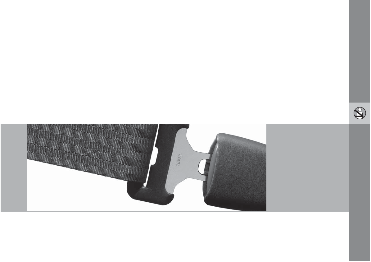
Buckling a seat belt
Pull the belt out far enough to insert the latch
plate into the receptacle until a distinct click is
heard. The seat belt retractor is normally
"unlocked" and you can move freely, provided
that the shoulder belt is not pulled out too far.
The retractor will lock up as follows:
if the belt is pulled out rapidly
•
G020995
during braking and acceleration
•
if the vehicle is leaning excessively
•
when driving in turns.
•
To make child seat installation easier, each
seat belt (except for the driver's belt) is equipped with a locking mechanism to help keep the
seat belt taut. See page 34 for more information regarding the Automatic Locking
Retractor (ALR).
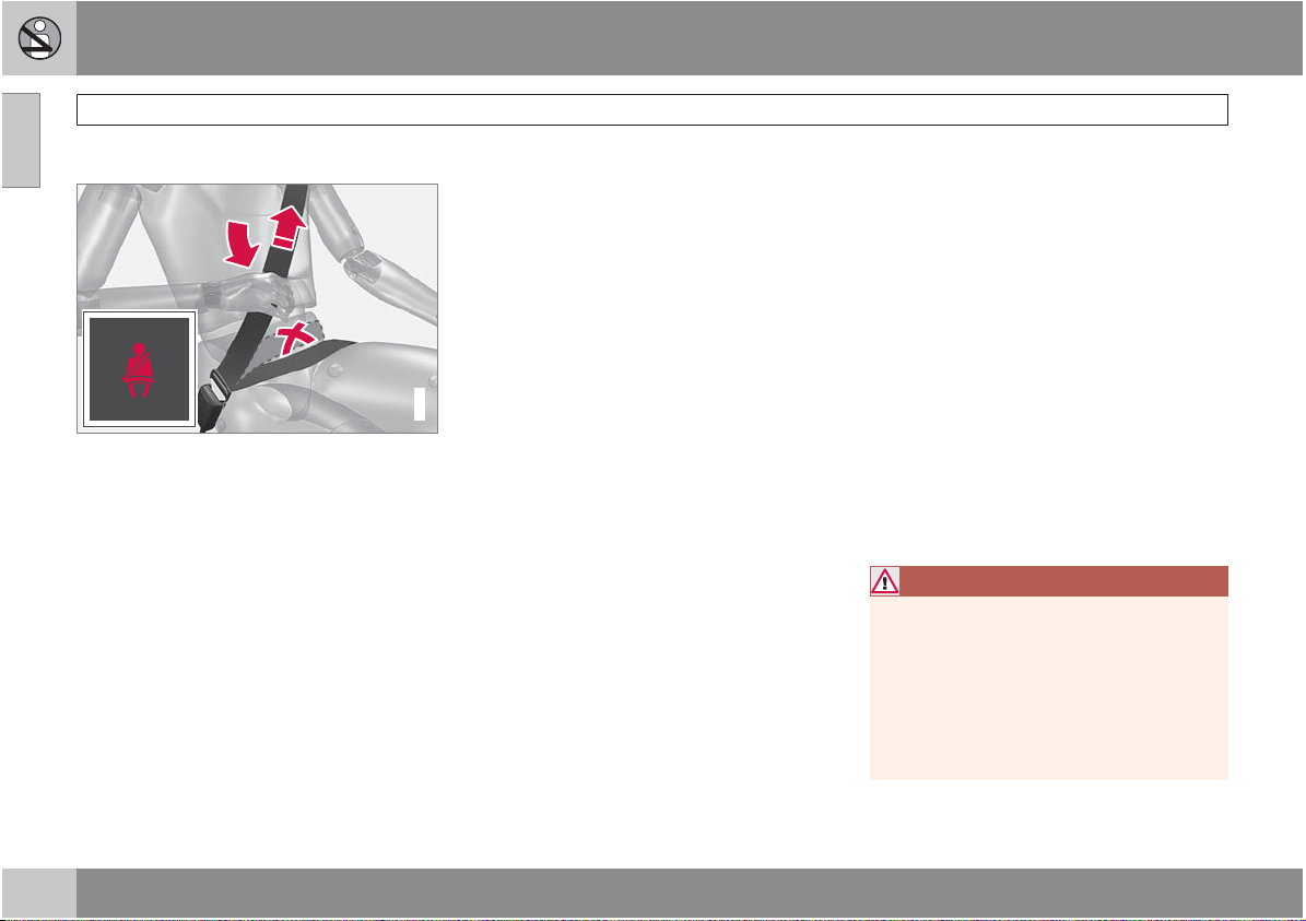
When wearing the seat belt remember:
The belt should not be twisted or turned.
•
The lap section of the belt must be posi-
•
tioned low on the hips (not pressing against
the abdomen).
Make sure that the shoulder belt is rolled
•
up into its retractor and that the shoulder
and lap belts are taut.
Seat belt reminder
The seat belt reminder consists of an audible
signal and a symbol in the instrument panel
that alert the driver if his/her seat belt is not
fastened.
Unbuckling the seat belt
To remove the seat belt, press the red section
on the seat belt receptacle. Before exiting the
vehicle, check that the seat belt retracts fully
after being unbuckled. If necessary, guide the
belt back into the retractor slot.
Seat belt maintenance
Check periodically that the seat belts are in
good condition. Use water and a mild detergent for cleaning. Check seat belt mechanism
function as follows: attach the seat belt and pull
rapidly on the strap.
WARNING
Never use a seat belt for more than one
occupant. Never wear the shoulder portion
of the belt under the arm, behind the back
or otherwise out of position. Such use could
cause injury in the event of an accident. As
seat belts lose much of their strength when
exposed to violent stretching, they should
be replaced after any collision, even if they
appear to be undamaged.
16
Page 17
01 Safety
WARNING
Never repair the belt yourself; have this
•
work done by a trained and qualified
Volvo service technician only.
Any device used to induce slack into the
•
shoulder belt portion of the three-point
belt system will have a detrimental
effect on the amount of protection available to you in the event of a collision.
The seat back should not be tilted too
•
far back. The shoulder belt must be taut
in order to function properly.
Do not use child safety seats or child
•
booster cushions/backrests in the front
passenger's seat. We also recommend
that children who have outgrown these
devices sit in the rear seat with the seat
belt properly fastened.
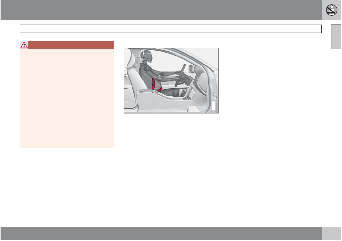
Seat belt use during pregnancy
The seat belt should always be worn during
pregnancy. But it is crucial that it be worn in the
correct way. The diagonal section should wrap
over the shoulder then be routed between the
breasts and to the side of the belly. The lap
section should lay flat over the thighs and as
low as possible under the belly. It must never
be allowed to ride upward. Remove all slack
from the belt and ensure that it fits close to the
body without any twists.
As a pregnancy progresses, pregnant drivers
should adjust their seats and steering wheel
such that they can easily maintain control of the
vehicle as they drive (which means they must
be able to easily operate the foot pedals and
steering wheel). Within this context, they
should strive to position the seat with as large
Seat belts
a distance as possible between their belly and
the steering wheel.
Child seats
Please refer to page 35 for information on
securing child seats with the seat belts.
G020998
01
17
Page 18
01 Safety
01
Supplemental Restraint System (SRS)
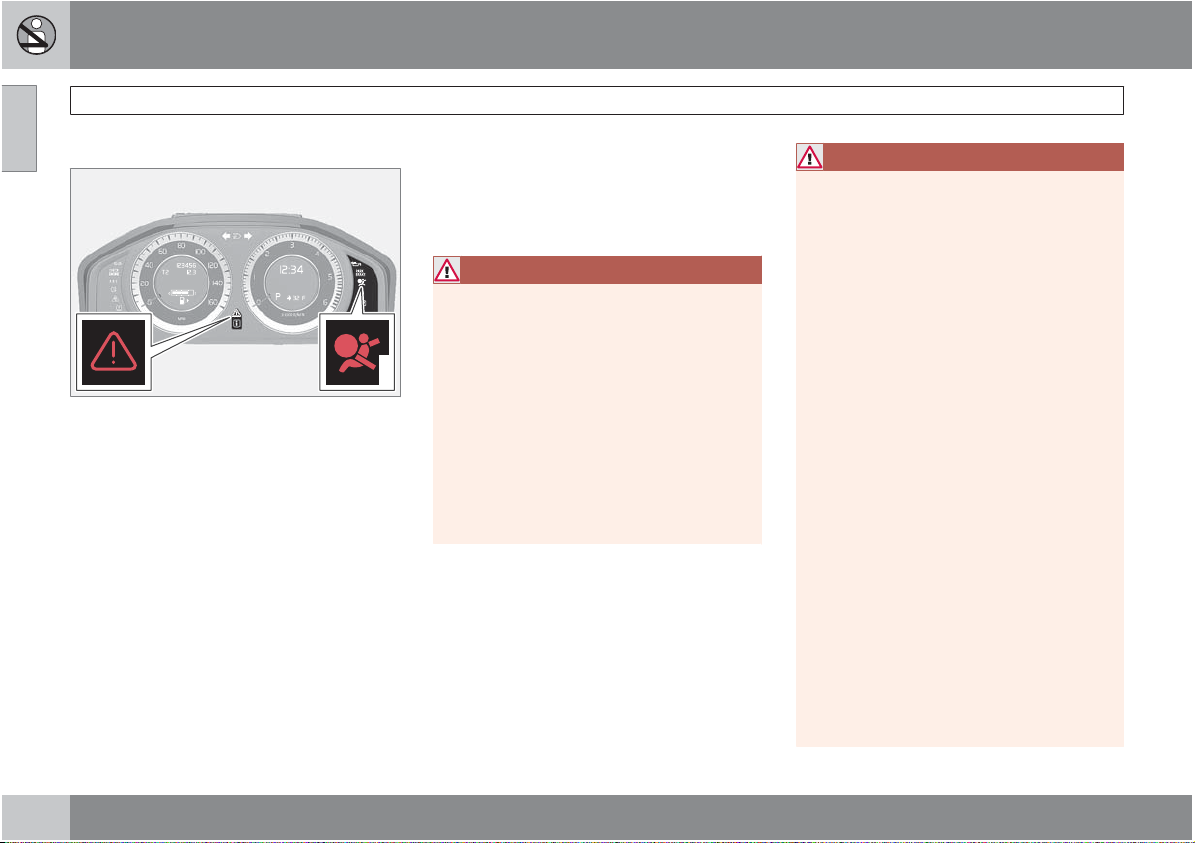
General information
Warning symbols in the instrument panel
As an enhancement to the three-point seat
belts, your Volvo is equipped with a Supplemental Restraint System (SRS). Volvo's SRS
consists of seat belt pretensioners, front airbags, side impact airbags, a front passenger
occupant weight sensor, and inflatable curtains. All of these systems are monitored by the
SRS control module. An SRS warning light in
the instrument panel (see the illustration) illuminates when the ignition is in modes I, II, or
III, and will normally go out after approximately
6 seconds if no faults are detected in the system.
Where applicable, a text message will also be
displayed when the SRS warning light illuminates. If this warning symbol is not functioning
properly, the general warning symbol illuminates and a text message will be displayed.
See also page 72 and page 74 for more
information about indicator and warning symbols.
WARNING
If the SRS warning light stays on after
•
the engine has started or if it illuminates
while you are driving, have the vehicle
inspected by a trained and qualified
G022831
Volvo service technician as soon as
possible.
Never try to repair any component or
•
part of the SRS yourself. Any interference in the system could cause malfunction and serious injury. All work on
these systems should be performed by
a trained and qualified Volvo service
technician.
WARNING
If your vehicle has been subjected to flood
conditions (e.g. soaked carpeting/standing
water on the floor of the vehicle) or if your
vehicle has become flood-damaged in any
way, do not attempt to start the vehicle or
insert the remote control into the ignition
slot before disconnecting the battery (see
below). This may cause airbag deployment
which could result in personal injury. Have
the vehicle towed to a trained and qualified
Volvo service technician for repairs.
Automatic transmission:
Before attempting to tow the vehicle, use
the following procedure to override the
shiftlock system to move the gear selector
to the neutral position:
1. Switch off the ignition for at least
10 minutes and disconnect the battery
2. Wait at least one minute.
3. Insert the remote key into the ignition
slot and press the Start button (without
depressing brake pedal) to go to ignition
mode II. See page 78 for more information.
4. Press firmly on the brake pedal.
5.
Move the gear selector from Park (P) to
the Neutral (N) position. see page 109
for information on manually overriding
the shiftlock system.
18
Page 19
01 Safety
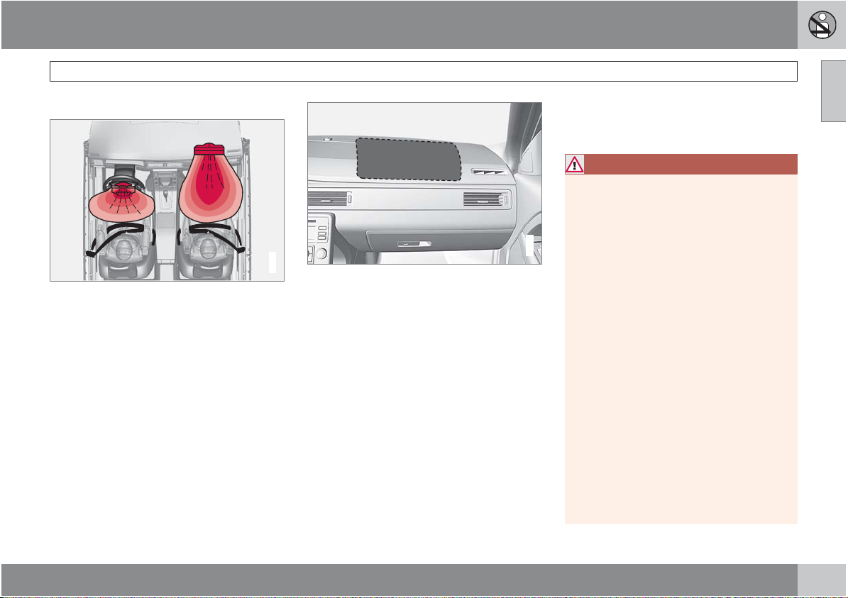
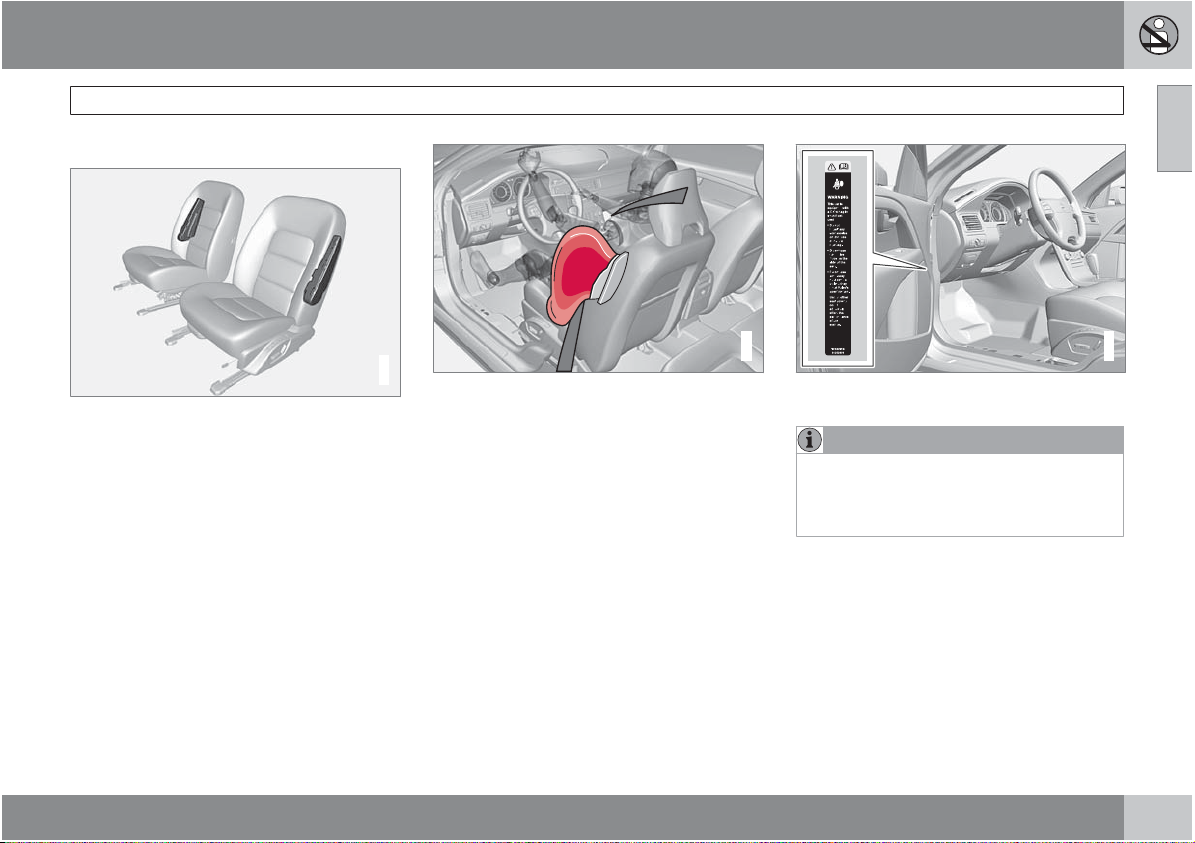
Front airbags
The front airbag system
The front airbags supplement the three-point
seat belts. For these airbags to provide the
protection intended, seat belts must be worn
at all times.
The front airbag system includes gas generators surrounded by the airbags, and deceleration sensors that activate the gas generators,
causing the airbags to be inflated with nitrogen
gas.
G018665
Location of the passenger's side front airbag
As the movement of the seats' occupants compresses the airbags, some of the gas is expelled at a controlled rate to provide better
cushioning. Both seat belt pretensioners also
deploy, minimizing seat belt slack. The entire
process, including inflation and deflation of the
airbags, takes approximately one fifth of a second.
The location of the front airbags is indicated by
SRS AIRBAG embossed on the steering wheel
pad and above the glove compartment, and by
decals on both sun visors and on the front and
far right side of the dash.
The driver's side front airbag is folded and
located in the steering wheel hub.
Supplemental Restraint System (SRS)
The passenger's side front airbag is folded
behind a panel located above the glove compartment.
WARNING
The airbags in the vehicle are designed
•
to be a SUPPLEMENT to–not a replacement for–the three-point seat belts. For
maximum protection, wear seat belts at
G021013
all times. Be aware that no system can
prevent all possible injuries that may
occur in an accident.
Never drive a vehicle with a steering
•
wheel-mounted airbag with your hands
on the steering wheel pad/airbag housing.
The front airbags are designed to help
•
prevent serious injury. Deployment
occurs very quickly and with considerable force. During normal deployment
and depending on variables such as
seating position, one may experience
abrasions, bruises, swellings, or other
injuries as a result from deployment of
one or both of the airbags.
When installing any accessory equip-
•
ment, make sure that the front airbag
system is not damaged. Any interference in the system could cause malfunction.
01
``
19
Page 20
01 Safety
01
Supplemental Restraint System (SRS)
Front airbag deployment
The front airbags are designed to deploy
•
during certain frontal or front-angular collisions, impacts, or decelerations, depending on the crash severity, angle, speed and
object impacted. The airbags may also
deploy in certain non-frontal collisions
where rapid deceleration occurs.
The SRS sensors, which trigger the front
•
airbags, are designed to react to both the
impact of the collision and the inertial
forces generated by it, and to determine if
the intensity of the collision is sufficient for
the seat belt pretensioners and/or airbags
to be deployed.
However, not all frontal collisions activate the
front airbags.
If the collision involves a nonrigid object
•
(e.g., a snow drift or bush), or a rigid, fixed
object at a low speed, the front airbags will
not necessarily deploy.
Front airbags do not normally deploy in a
•
side impact collision, in a collision from the
rear or in a rollover situation.
The amount of damage to the bodywork
•
does not reliably indicate if the airbags
should have deployed or not.
WARNING
Do not use child safety seats or child
•
booster cushions/backrests in the front
passenger's seat. We also recommend
that occupants under 4 feet 7 inches
(140 cm) in height who have outgrown
these devices sit in the rear seat with the
seat belt fastened
Never drive with the airbags deployed.
•
The fact that they hang out can impair
the steering of your vehicle. Other
safety systems can also be damaged.
The smoke and dust formed when the
•
airbags are deployed can cause skin
and eye irritation in the event of prolonged exposure.
Should you have questions about any component in the SRS system, please contact a
trained and qualified Volvo service technician
or Volvo Customer Support:
In the USA
Volvo Cars of North America, LLC
Customer Care Center
P.O. Box 914 Rockleigh, New Jersey
07647-0914
1
.
1-800-458-1552
www.volvocars.us
In Canada
Volvo Cars of Canada Corp.
National Customer Service
175 Gordon Baker Road
North York, Ontario M2H 2N7
1-800-663-8255
www.volvocanada.com
1
See also the Occupant Weight Sensor information see page 23.
20
Page 21
01 Safety
NOTE
Deployment of front airbags occurs only
•
one time during an accident. In a collision where deployment occurs, the airbags and seat belt pretensioners activate. Some noise occurs and a small
amount of powder is released. The
release of the powder may appear as
smoke-like matter. This is a normal
characteristic and does not indicate fire.
Volvo's front airbags use special sen-
•
sors that are integrated with the front
seat buckles. The point at which the airbag deploys is determined by whether
or not the seat belt is being used, as well
as the severity of the collision.
Collisions can occur where only one of
•
the airbags deploys. If the impact is less
severe, but severe enough to present a
clear injury risk, the airbags are triggered at partial capacity. If the impact is
more severe, the airbags are triggered
at full capacity.
Airbag decals
Airbag decal on the far right end of the passenger's dashboard
Airbag decal on the outside of both sun visors
Supplemental Restraint System (SRS)
G032244
Airbag decal on passenger's side dashboard
G008335
01
G032527
``
21
Page 22
01 Safety
01
Supplemental Restraint System (SRS)
WARNING
Children must never be allowed in the
•
front passenger's seat. Volvo recommends that ALL occupants (adults and
children) shorter than 4 feet 7 inches
(140 cm) be seated in the back seat of
any vehicle with a passenger-side front
airbag.
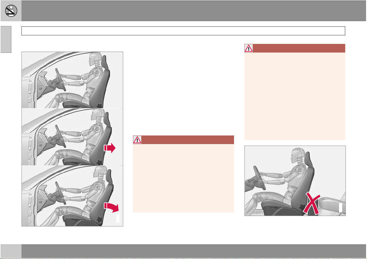
Occupants in the front passenger's seat
•
must never sit on the edge of the seat,
sit leaning toward the instrument panel
or otherwise sit out of position.
The occupant's back must be as upright
•
as comfort allows and be against the
seat back with the seat belt properly
fastened.
Feet must be on the floor, e.g., not on
•
the dash, seat or out of the window.
WARNING
No objects or accessory equipment,
•
e.g. dashboard covers, may be placed
on, attached to, or installed near the air
bag hatch (the area above the glove
compartment) or the area affected by
airbag deployment (see the illustration
on page 19).
There should be no loose articles, such
•
as coffee cups on the floor, seat, or
dashboard area.
Never try to open the airbag cover on
•
the steering wheel or the passenger's
side dashboard. This should only be
done by a trained and qualified Volvo
service technician.
Failure to follow these instructions can
•
result in injury to the vehicle occupants.
22
Page 23
01 Safety
General information
2
2
Occupant Weight Sensor (OWS) indicator light
Disabling the passenger's side front
airbag
Volvo recommends that ALL occupants (adults
and children) shorter than 4 feet 7 inches
(140 cm) be seated in the back seat of any
vehicle with a front passenger side airbag, and
be properly restrained for their size and weight.
For child safety recommendations, see
page 34.
The Occupant Weight Sensor (OWS) is
designed to meet the regulatory requirements
of Federal Motor Vehicle Safety Standard
(FMVSS) 208 and is designed to disable (will
not inflate) the passenger's side front airbag
under certain conditions.
The OWS works with sensors that are part of
the front passenger's seat and seat belt. The
sensors are designed to detect the presence of
a properly seated occupant and determine if
the passenger's side front airbag should be
enabled (may inflate) or disabled (will not
inflate).
The OWS will disable (will not inflate) the passenger's side front airbag when:
the front passenger's seat is unoccupied,
•
G017724
or has small/medium objects in the front
seat,
the system determines that an infant is
•
present in a rear-facing infant seat that is
installed according to the manufacturer's
instructions,
the system determines that a small child is
•
present in a forward-facing child restraint
that is installed according to the manufacturer's instructions,
the system determines that a small child is
•
present in a booster seat,
a front passenger takes his/her weight off
•
of the seat for a period of time,
a child or a small person occupies the front
•
passenger's seat.
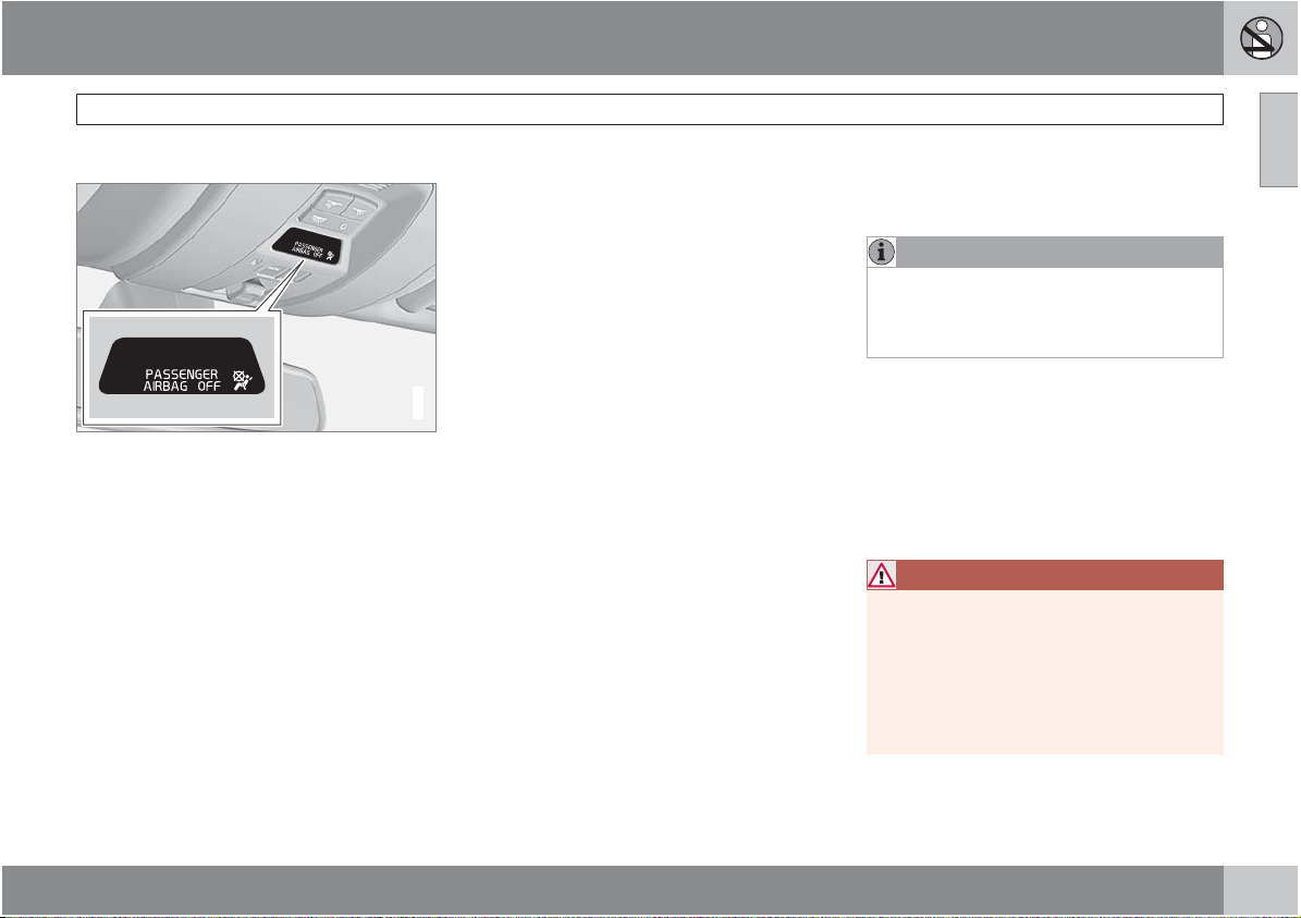
The OWS uses a PASSENGER AIRBAG OFF
indicator lamp which will illuminate and stay on
to remind you that the passenger's side front
Occupant Weight Sensor
airbag is disabled. The PASSENGER AIRBAG
OFF indicator lamp is located in the overhead
console, near the base of the rearview mirror.
NOTE
When the ignition is switched on, the OWS
indicator light will go on for up to 10 seconds
while the system performs a self-diagnostic
test.
However, if a fault is detected in the system:
The OWS indicator light will stay on
•
The SRS warning light (see page 18) will
•
come on and stay on
The message PASS. AIRBAG OFF
•
SERVICE URGENT
the information display.
WARNING
If a fault in the system is detected and indicated as described, be aware that the passenger's side front airbag will not deploy in
the event of a collision. In this case, the SRS
system and Occupant Weight Sensor
should be inspected by a trained and qualified Volvo service technician as soon as
possible.
will be displayed in
01
``
23
Page 24
01 Safety
01
Occupant Weight Sensor
WARNING
Never try to open, remove, or repair any
•
components in the OWS system. This
could result in system malfunction.
Maintenance or repairs should only be
carried out by an a trained and qualified
Volvo service technician.
The front passenger's seat should not
•
be modified in any way. This could
reduce pressure on the seat cushion,
which might interfere with the OWS system's function.
Passenger's seat
occupancy sta-
OWS indicator light
status
Passenger's side
front airbag status
tus
Seat unoccupied
Seat occupied by low
weight
occupant/
A
object
Seat occupied by
heavy occupant/object
A
Volvo recommends that children always be properly
restrained in appropriate child restraints in the rear seats. Do
not assume that the passenger's side front airbag is disabled
unless the PASSENGER AIRBAG OFF indicator lamp is lit.
Make sure the child restraint is properly installed. If there is
any doubt as to the status of the passenger's side front airbag, move the child restraint to the rear seat.
The OWS is designed to enable (may inflate)
the passenger's side front airbag anytime the
system senses that a person of adult size is
sitting properly in the front passenger's seat.
OWS indicator light
lights up.
OWS indicator light
lights up
OWS indicator light is
not lit
Passenger's
side front
airbag disabled
Passenger's
side front
airbag disabled
Passenger's
side front
airbag enabled
The PASSENGER AIRBAG OFF indicator lamp
will be off and remain off.
If a person of adult size is sitting in the front
passenger's seat, but the PASSENGER AIRBAG OFF indicator lamp is on, it is possible that
the person isn't sitting properly in the seat. If
this happens:
Turn the vehicle off and ask the person to
•
place the seatback in an upright position.
Have the person sit upright in the seat,
•
centered on the seat cushion, with the person's legs comfortably extended.
Restart the vehicle and have the person
•
remain in this position for about two
minutes. This will allow the system to
detect that person and enable the passenger's frontal airbag.
If the PASSENGER AIRBAG OFF indicator
•
lamp remains on even after this, the person
should be advised to ride in the rear seat.
This condition reflects limitations of the OWS
classification capability. It does not indicate
OWS malfunction.
Modifications
If you are considering modifying your vehicle in
any way to accommodate a disability, for
example by altering or adapting the driver's or
front passenger's seat(s) and/or airbag systems, please contact Volvo at:
24
Page 25
01 Safety
In the USA
Volvo Cars of North America, LLC
Customer Care Center
P.O. Box 914 Rockleigh, New Jersey
07647-0914
1-800-458-1552
In Canada
Volvo Cars of Canada Corp.
National Customer Service
175 Gordon Baker Road North York, Ontario
M2H 2N7
1-800-663-8255
WARNING
No objects that add to the total weight
•
on the seat should be placed on the
front passenger's seat. If a child is
seated in the front passenger's seat
with any additional weight, this extra
weight could cause the OWS system to
enable the airbag, which might cause it
to deploy in the event of a collision,
thereby injuring the child.
The seat belt should never be wrapped
•
around an object on the front passenger's seat. This could interfere with the
OWS system's function.
The front passenger's seat belt should
•
never be used in a way that exerts more
pressure on the passenger than normal.
This could increase the pressure exerted on the weight sensor by a child, and
could result in the airbag being enabled,
which might cause it to deploy in the
event of a collision, thereby injuring the
child.
Occupant Weight Sensor
WARNING
Keep the following points in mind with
•
respect to the OWS system. Failure to
follow these instructions could
adversely affect the system's function
and result in serious injury to the occupant of the front passenger's seat:
The full weight of the front seat passen-
•
ger should always be on the seat cushion. The passenger should never lift
him/herself off the seat cushion using
the armrest in the door or the center
console, by pressing the feet on the
floor, by sitting on the edge of the seat
cushion, or by pressing against the
backrest in a way that reduces pressure
on the seat cushion. This could cause
OWS to disable the front, passenger's
side airbag.
01
``
25
Page 26
01 Safety
01
Occupant Weight Sensor
WARNING
Do not place any type of object on the
•
front passenger's seat in such a way
that jamming, pressing, or squeezing
occurs between the object and the front
seat, other than as a direct result of the
correct use of the Automatic Locking
Retractor/Emergency Locking Retractor (ALR/ELR) seat belt (see page 34).
No objects should be placed under the
•
front passenger's seat. This could interfere with the OWS system's function.
26
Page 27
01 Safety
General information
Location of the side impact (SIPS) airbags (front
seats only)
As an enhancement to the structural side
impact protection built into your vehicle, it is
also equipped with Side Impact Protection
System (SIPS) airbags.
The SIPS airbag system is designed to help
increase occupant protection in the event of
certain side impact collisions. The SIPS airbags are designed to deploy only during certain side-impact collisions, depending on the
crash severity, angle, speed and point of
impact.
G020694
SIPS airbag deployment
SIPS airbag deployment (one airbag) occurs
only on the side of the vehicle affected by the
impact. The airbags are not designed to deploy
in all side impact situations.
Side impact protection (SIPS) airbags
G024377
SIPS decal on the front of the driver's door opening
NOTE
SIPS airbag deployment (one airbag) occurs
only on the side of the vehicle affected by
the impact. The airbags are not designed to
deploy in all side impact situations.
Components in the SIPS airbag system
This SIPS airbag system consists of a gas generator, the side airbag modules built into the
outboard sides of both front seat backrests,
and electronic sensors/wiring.
01
G032254
``
27
Page 28
01 Safety
01
Side impact protection (SIPS) airbags
WARNING
The SIPS airbag system is a supple-
•
ment to the structural Side Impact Protection System and the three-point seat
belt system. It is not designed to deploy
during collisions from the front or rear of
the vehicle or in rollover situations.
The use of seat covers on the front seats
•
may impede SIPS airbag deployment.
No objects, accessory equipment or
•
stickers may be placed on, attached to
or installed near the SIPS airbag system
or in the area affected by SIPS airbag
deployment.
Never try to open or repair any compo-
•
nents of the SIPS airbag system. This
should be done only by a trained and
qualified Volvo service technician.
In order for the SIPS airbag to provide
•
its best protection, both front seat
occupants should sit in an upright position with the seat belt properly fastened.
Failure to follow these instructions can
•
result in injury to the occupants of the
vehicle in the event of an accident.
28
Page 29
01 Safety
General information
This system consists of inflatable curtains
located along the sides of the roof liners,
stretching from the center of both front side
windows to the rear edge of the rear side door
windows. It is designed to help protect the
heads of the occupants of the front seats and
the occupant of the outboard rear seating positions in certain side impact collisions.
In certain side impacts, both the Inflatable Curtain (VIC) and the Side Impact Airbag System
(SIPS airbag) will deploy. The VIC and the SIPS
airbag deploy simultaneously.
G020665
WARNING
The VIC system is a supplement to the
•
Side Impact Protection System. It is not
designed to deploy during collisions
from the front or rear of the vehicle or in
rollover situations.
Never try to open or repair any compo-
•
nents of the VIC system. This should be
done only by a trained and qualified
Volvo service technician.
Never hang heavy items from the ceiling
•
handles. This could impede deployment
of the Inflatable Curtain.
The rear seat should not be loaded to a
•
level higher than 2 in. (5 cm) below the
upper edge of the rear side windows.
Objects placed higher than this level
could impede the function of the Volvo
Inflatable Curtain.
Volvo Inflatable Curtain (VIC)
WARNING
In order for the VIC to provide its best protection, both front seat occupants and both
outboard rear seat occupants should sit in
an upright position with the seat belt properly fastened; adults using the seat belt and
children using the proper child restraint system. Only adults should sit in the front seats.
Children must never be allowed in the front
passenger seat, see page 34 for guidelines. Failure to follow these instructions can
result in injury to the vehicle occupants in an
accident.
01
NOTE
If the inflatable curtain deploys, it remains
inflated for approximately 3 seconds.
29
Page 30
01 Safety
01
Whiplash Protection System – WHIPS
General information
Whiplash Protection System (WHIPS) –
front seats only
The WHIPS system consists of specially
designed hinges and brackets on the front seat
backrests designed to help absorb some of the
energy generated in a collision from the rear
(when the vehicle is rear-ended).
In the event of a collision of this type, the hinges
and brackets of the front seat backrests are
designed to change position slightly to allow
the backrest/head restraint to help support the
occupant's head before moving slightly rearward. This movement helps absorb some of
the forces that could result in whiplash.
WARNING
The WHIPS system is designed to sup-
•
plement the other safety systems in
your vehicle. For this system to function
properly, the three-point seat belt must
be worn. Please be aware that no system can prevent all possible injuries that
may occur in an accident.
The WHIPS system is designed to func-
•
tion in certain collisions from the rear,
depending on the crash severity, angle
and speed.
WARNING
Occupants in the front seats must never
•
sit out of position. The occupant's back
must be as upright as comfort allows
and be against the seat back with the
seat belt properly fastened.
If your vehicle has been involved in a
•
rear-end collision, the front seat backrests must be inspected by a trained and
qualified Volvo service technician, even
if the seats appear to be undamaged.
Certain components in the WHIPS system may need to be replaced.
Do not attempt to service any compo-
•
nent in the WHIPS system yourself.
G021842
30
G021018
Page 31

01 Safety
WARNING
Boxes, suitcases, etc. wedged behind
•
the front seats could impede the function of the WHIPS system.
If the rear seat backrests are folded
•
down, cargo must be secured to prevent it from sliding forward against the
front seat backrests in the event of a
collision from the rear. This could interfere with the action of the WHIPS system.
WARNING
Any contact between the front seat backrests and the folded rear seat or a rear-facing
child seat could impede the function of the
WHIPS system. If the rear seat is folded
down, the occupied front seats must be
adjusted forward so that they do not touch
the folded rear seat.
G018567
Whiplash Protection System – WHIPS
01
31
Page 32

01 Safety
01
Crash mode
Driving after a collision
If the vehicle has been involved in a collision,
the text SAFETY MODE SEE MANUAL may
appear in the information display. This indicates that the vehicle's functionality has been
reduced.
NOTE
This text can only be shown if the display is
undamaged and the vehicle's electrical system is intact.
Safety mode is a feature that is triggered if one
or more of the safety systems (e.g. front or side
airbags, an inflatable curtain, or one or more of
the seat belt pretensioners) has deployed. The
collision may have damaged an important
function in the vehicle, such as the fuel lines,
sensors for one of the safety systems, the
brake system, etc.
WARNING
Never attempt to repair the vehicle
•
yourself or to reset the electrical system
G022831
after the vehicle has displayed SAFETY
MODE SEE MANUAL
result in injury or improper system function.
Restoring the vehicle to normal operat-
•
ing status should only be done by a
trained and qualified Volvo service technician.
After SAFETY MODE SEE MANUAL
•
has been displayed, if you detect the
odor of fuel vapor, or see any signs of
fuel leakage, do not attempt to start the
vehicle. Leave the vehicle immediately.
. This could
Attempting to start the vehicle
If damage to the vehicle is minor and there is
no fuel leakage, you may attempt to start the
vehicle. To do so:
1. Remove the remote control from the ignition slot.
2. Reinsert the remote in the ignition slot. The
vehicle will then attempt to reset Safety
mode to normal status.
3. Try to start the vehicle.
Moving the vehicle
If the electrical system is able to reset system
status to normal (
MANUAL
play), the vehicle may be moved carefully from
its present position, if for example, it is blocking
traffic. It should, however, not be moved farther
than is absolutely necessary.
SAFETY MODE SEE
will no longer be shown in the dis-
WARNING
Even if the vehicle appears to be drivable
after Safety mode has been set, it should
not be driven or towed (pulled by another
vehicle). There may be concealed damage
that could make it difficult or impossible to
control. The vehicle should be transported
on a flatbed tow truck to a trained and qualified Volvo service technician for inspection/
repairs.
32
Page 33

01 Safety
Children should be seated safely
Volvo recommends the proper use of restraint
systems for all occupants including children.
Remember that, regardless of age and size, a
child should always be properly restrained in a
vehicle.
Your vehicle is also equipped with ISOFIX/
LATCH attachments, which make it more convenient to install child seats.
Some restraint systems for children are
designed to be secured in the vehicle by lap
belts or the lap portion of a lap-shoulder belt.
Such child restraint systems can help protect
children in vehicles in the event of an accident
only if they are used properly. However, children could be endangered in a crash if the child
restraints are not properly secured in the vehicle. Failure to follow the installation instructions
for your child restraint can result in your child
striking the vehicle's interior in a sudden stop.
Holding a child in your arms is NOT a suitable
substitute for a child restraint system. In an
accident, a child held in a person's arms can
be crushed between the vehicle's interior and
an unrestrained person. The child could also be
injured by striking the interior, or by being ejected from the vehicle during a sudden maneuver
or impact. The same can also happen if the
infant or child rides unrestrained on the seat.
Other occupants should also be properly
restrained to help reduce the chance of injuring
or increasing the injury of a child.
All states and provinces have legislation governing how and where children should be carried in a vehicle. Find out the regulations
existing in your state or province. Recent accident statistics have shown that children are
safer in rear seating positions than front seating
positions when properly restrained. A child
restraint system can help protect a child in a
vehicle. Here's what to look for when selecting
a child restraint system:
It should have a label certifying that it meets
applicable Federal Motor Vehicle Safety
Standards (FMVSS 213) – or in Canada,
CMVSS 213.
Make sure the child restraint system is
approved for the child's height, weight and
development – the label required by the standard or regulation, or instructions for infant
restraints, typically provide this information.
In using any child restraint system, we urge you
to carefully look over the instructions that are
provided with the restraint. Be sure you understand them and can use the device properly
and safely in this vehicle. A misused child
restraint system can result in increased injuries
for both the infant or child and other occupants
in the vehicle.
Child safety
When a child has outgrown the child safety
seat, you should use the rear seat with the
standard seat belt fastened. The best way to
help protect the child here is to place the child
on a cushion so that the seat belt is properly
located on the hips (see the illustration on page
41). Legislation in your state or province may
mandate the use of a child seat or cushion in
combination with the seat belt, depending on
the child's age and/or size. Please check local
regulations.
A specially designed and tested booster cushion (not available in Canada) can be obtained
from your Volvo retailer for children weighing
33 – 80 lb. (15 – 36 kg) and 38 – 54 inches
(97 – 137 cm) in height.
01
``
33
Page 34

01 Safety
01
Child safety
WARNING
Do not use child safety seats or child
•
booster cushions/backrests in the front
passenger's seat. We also recommend
that children under 4 feet 7 inches
(140 cm) in height who have outgrown
these devices sit in the rear seat with the
seat belt fastened.
Keep vehicle doors and trunk locked
•
and keep remote controls out of a
child’s reach. Unsupervised children
could lock themselves in an open trunk
and risk injury. Children should be
taught not to play in vehicles.
On hot days, the temperature in the
•
vehicle interior can rise very quickly.
Exposure to these high temperatures
for even a short period of time can
cause heat-related injury or death.
Small children are particularly at risk.
Automatic Locking Retractor/
Emergency Locking Retractor (ALR/
ELR)
To make child seat installation easier, each
seat belt (except for the driver's belt) is equipped with a locking mechanism to help keep the
seat belt taut.
When attaching the seat belt to a child
seat:
1. Attach the seat belt to the child seat
according to the child seat manufacturer's
instructions.
2. Pull the seat belt out as far as possible.
3. Insert the seat belt latch plate into the
buckle (lock) in the usual way.
4. Release the seat belt and pull it taut around
the child seat.
A sound from the seat belt retractor will be
audible at this time and is normal. The belt will
now be locked in place. This function is automatically disabled when the seat belt is
unlocked and the belt is fully retracted.
WARNING
Do not use child safety seats or child
booster cushions/backrests in the front
passenger's seat. We also recommend that
children who have outgrown these devices
sit in the rear seat with the seat belt properly
fastened.
Volvo's recommendations
Why does Volvo believe that no child should sit
in the front seat of a vehicle? It's quite simple
really. A front airbag is a very powerful device
designed, by law, to help protect an adult.
Because of the size of the airbag and its speed
of inflation, a child should never be placed in
the front seat, even if he or she is properly belted or strapped into a child safety seat. Volvo
has been an innovator in safety for over seventy-five years, and we'll continue to do our
part. But we need your help. Please remember
to put your children in the back seat, and
buckle them up.
Volvo has some very specific
recommendations:
Always wear your seat belt.
•
Airbags are a SUPPLEMENTAL safety
•
device which, when used with a threepoint seat belt can help reduce serious
injuries during certain types of accidents.
Volvo recommends that you do not disconnect the airbag system in your vehicle.
Volvo strongly recommends that everyone
•
in the vehicle be properly restrained.
Volvo recommends that ALL occupants
•
(adults and children) shorter than 4 feet
7 inches (140 cm) be seated in the back
seat of any vehicle with a front passenger
side airbag.
Drive safely!
34
Page 35

01 Safety
Child restraints
Infant seat
There are three main types of child restraint
systems: infant seats, convertible seats, and
booster cushions. They are classified according to the child's age and size.
The following section provides general infor-
mation on securing a child restraint using a
three-point seat belt. Refer to page 42–43
for information on securing a child restraint
using ISOFIX lower anchors and/or top tether
anchorages.
G022840
Convertible seat
WARNING
A child seat should never be used in the
front passenger seat of any vehicle with a
front passenger airbag – not even if the
"Passenger airbag off" symbol near the
rear-view mirror is illuminated (on vehicles
equipped with Occupant Weight Sensor). If
the severity of an accident were to cause the
airbag to inflate, this could lead to serious
injury or death to a child seated in this position.
Child restraint systems
G022847
Booster cushion
WARNING
Always refer to the child restraint manufacturer's instructions for detailed information
on securing the restraint.
01
G023269
``
35
Page 36

01 Safety
01
Child restraint systems
WARNING
When not in use, keep the child restraint
•
system secured or remove it from the
passenger compartment to help prevent it from injuring passengers in the
event of a sudden stop or collision.
A small child's head represents a con-
•
siderable part of its total weight and its
neck is still very weak. Volvo recommends that children up to age 4 travel,
properly restrained, facing rearward. In
addition, Volvo recommends that children should ride rearward facing, properly restrained, as long as possible.
36
Page 37

01 Safety
Securing an infant seat with a seat belt
Do not place the infant seat in the front passenger's sea
NOTE
Refer to page 42–43 for information on
securing a child restraint using ISOFIX lower
anchors and/or top tether anchorages.
1. Place the infant seat in the rear seat of the
vehicle.
2. Attach the seat belt to the infant seat
according to the manufacturer's instructions.
G022844
Positioning the seat belt through the infant seat
WARNING
An infant seat must be in the rear-facing
•
position only.
The infant seat should not be positioned
•
behind the driver's seat unless there is
adequate space for safe installation.
Infant seats
WARNING
A child seat should never be used in the
front passenger seat of any vehicle with a
front passenger airbag – not even if the
"Passenger airbag off" symbol near the
rear-view mirror is illuminated (on vehicles
equipped with Occupant Weight Sensor). If
the severity of an accident were to cause the
airbag to inflate, this could lead to serious
injury or death to a child seated in this position.
G023270
3. Fasten the seat belt by inserting the latch
plate into the buckle (lock) until a distinct
click is audible.
Fasten the seat belt
01
G023271
``
37
Page 38

01 Safety
01
Infant seats
Pull out the shoulder section of the seat belt
4. Pull the shoulder section of the seat belt
out as far as possible to activate the belt's
automatic locking function.
NOTE
The locking retractor will automatically
release when the seat belt is unbuckled and
allowed to retract fully.
5. Press the infant seat firmly in place, let the
seat belt retract and pull it taut. A sound
from the seat belt retractor's automatic
locking function will be audible at this time
and is normal. The seat belt should now be
locked in place.
G022846
Ensure that the seat is securely in place
6. Push and pull the infant seat to ensure that
it is held securely in place by the seat belt.
WARNING
It should not be possible to move the child
restraint more than 1 in. (2.5 cm) in any
direction.
The infant seat can be removed by unbuckling
the seat belt and letting it retract completely.
G022850
38
Page 39

01 Safety
Securing a convertible seat with a seat
belt
Do not place the convertible seat in the front passenger's seat
NOTE
Refer to pages 42 and 43s for information on securing a child restraint using ISOFIX lower anchors and/or top tether anchorages.
Convertible seats can be used in either a forward or rearward-facing position, depending
on the age and size of the child.
Route the seat belt through the convertible seat
G018630
WARNING
Always use a convertible seat that is suitable for the child's age and size. See the
convertible seat manufacturer's recommendations.
1. Place the convertible seat in the rear seat
of the vehicle.
Convertible seats
WARNING
A small child's head represents a con-
•
siderable part of its total weight and its
neck is still very weak. Volvo recommends that children up to age 4 travel,
properly restrained, facing rearward. In
addition, Volvo recommends that children should ride rearward facing, properly restrained, as long as possible.
Convertible child seats should be instal-
•
G022847
led in the rear seat only.
A rear-facing convertible seat should not
•
be positioned behind the driver's seat
unless there is adequate space for safe
installation.
2. Attach the seat belt to the convertible seat
according to the manufacturer's instructions.
01
``
39
Page 40

01 Safety
01
Convertible seats
Fasten the seat belt
3. Fasten the seat belt by inserting the latch
plate into the buckle (lock) until a distinct
click is audible.
4. Pull the shoulder section of the seat belt
out as far as possible to activate the belt's
automatic locking function.
NOTE
The locking retractor will automatically
release when the seat belt is unbuckled and
allowed to retract fully.
5. Press the convertible seat firmly in place,
let the seat belt retract and pull it taut. A
sound from the seat belt retractor's automatic locking function will be audible at this
time and is normal. The seat belt should
now be locked in place.
G022848
Pull out the shoulder section of the seat belt
6. Push and pull the convertible seat to
ensure that it is held securely in place by
the seat belt.
WARNING
It should not be possible to move the child
restraint more than 1 in. (2.5 cm) in any
direction.
The convertible seat can be removed by
unbuckling the seat belt and letting it retract
completely.
Ensure that the seat is securely in place
G022849
WARNING
A child seat should never be used in the
front passenger seat of any vehicle with a
front passenger airbag – not even if the
"Passenger airbag off" symbol near the
rear-view mirror is illuminated (on vehicles
equipped with Occupant Weight Sensor). If
the severity of an accident were to cause the
airbag to inflate, this could lead to serious
injury or death to a child seated in this position.
G022850
40
Page 41

01 Safety
Securing a booster cushion
Position the child correctly on the booster cushion
Booster cushions are recommended for children who have outgrown convertible seats.
1. Place the booster cushion in the rear seat
of the vehicle.
2. With the child properly seated on the
booster cushion, attach the seat belt to or
around the cushion according to the manufacturer's instructions.
3. Fasten the seat belt by inserting the latch
plate into the buckle (lock) until a distinct
click is audible.
G022851
Positioning the seat belt
4. Ensure that the seat belt is pulled taut and
fits snugly around the child.
WARNING
The hip section of the three-point seat
•
belt must fit snugly across the child's
hips, not across the stomach.
The shoulder section of the three-point
•
seat belt should be positioned across
the chest and shoulder.
The shoulder belt must never be placed
•
behind the child's back or under the
arm.
G022852
Booster cushions
01
41
Page 42

01 Safety
01
ISOFIX lower anchors
Using the ISOFIX lower child seat
anchors
ISOFIX lower child restraint anchors
Lower anchors for ISOFIX-equipped child
seats are located in the rear, outboard seats,
hidden below the backrest cushions. Symbols
on the seat back upholstery mark the anchor
positions as shown. To access the anchors,
kneel on the seat cushion and locate the
anchors by feel. Always follow your child seat
manufacturer's installation instructions, and
use both ISOFIX lower anchors and top tethers
whenever possible.
To access the anchors
1. Put the child restraint in position.
2. Kneel on the child restraint to press down
the seat cushion and locate the anchors by
feel.
3. Fasten the attachment on the child
restraint's lower straps to the ISOFIX lower
anchors.
4. Firmly tension the lower child seat straps
according to the manufacturer's instructions.
NOTE
The rear seat's center position is not
•
G021064
equipped with ISOFIX lower anchors.
When installing a child restraint in this
position, attach the restraint's top tether
strap (if it is so equipped) to the top
tether anchorage point and secure the
restraint with the vehicle's center seat
belt.
Always follow your child seat manufac-
•
turer's installation instructions, and use
both ISOFIX lower anchors and top
tethers whenever possible.
Fasten the attachment correctly to the ISOFIX
lower anchors
WARNING
Be sure to fasten the attachment cor-
•
rectly to the anchor (see the illustration).
If the attachment is not correctly fastened, the child restraint may not be
properly secured in the event of a collision.
The ISOFIX lower child restraint
•
anchors are only intended for use with
child seats positioned in the outboard
seating positions. These anchors are
not certified for use with any child
restraint that is positioned in the center
seating position. When securing a child
restraint in the center seating position,
use only the vehicle's center seat belt.
G018631
42
Page 43

01 Safety
Child restraint anchorages
Your Volvo is equipped with child restraint top
tether anchorages in the rear seat. They are
located on the rear parcel shelf.
Securing a child seat
1. Place the child restraint on the rear seat.
2. Fold up the plastic cover over the anchorage to be used.
3. Route the top tether strap under the head
restraint and attach it to the anchor.
4. Attach lower tether straps to the lower ISOFIX/LATCH anchors. If the child restraint is
not equipped with lower tether straps, or
the restraint is used in the center seating
position, follow instructions for securing a
child restraint using the Automatic Locking
Retractor seat belt (see page 34).
5. Firmly tension all straps.
Refer also to the child seat manufacturer's
instructions for information on securing the
child seat.
WARNING
Never route a top tether strap over the
•
top of the head restraint. The strap
G021068
should be routed beneath the head
restraint.
Child restraint anchorages are designed
•
to withstand only those loads imposed
by correctly fitted child restraints. Under
no circumstances are they to be used
for adult seat belts or harnesses. The
anchorages are not able to withstand
excessive forces on them in the event of
collision if full harness seat belts or adult
seat belts are installed to them. An adult
who uses a belt anchored in a child
restraint anchorage runs a great risk of
suffering severe injuries should a collision occur.
Do not install rear speakers that require
•
the removal of the top tether anchors or
interfere with the proper use of the top
tether strap.
Top tether anchors
01
43
Page 44

01 Safety
01
Child restraint registration and recalls
Registering a child restraint
Child restraints could be recalled for safety
reasons. You must register your child restraint
to be reached in a recall. To stay informed
about child safety seat recalls, be sure to fill out
and return the registration card that comes
with new child restraints.
Child restraint recall information is readily available in both the U.S. and Canada. For recall
information in the U.S., call the U.S. Government's Auto Safety Hotline at 1-800-424-9393.
In Canada, visit Transport Canada's Child
Safety website at http://www.tc.gc.ca/
roadsafety/childsafety/menu.htm.
44
Page 45

01 Safety
Integrated booster cushion (option)
Volvo's optional integrated booster cushion is
located in the center seating position. This
booster cushion has been specially designed
to help safeguard a child in the rear seat. It
should be stowed (folded up into the rear seat
backrest) when not in use. When using an integrated booster cushion, the child must be
secured with the vehicle's three-point seat
belt.
1
Use this booster cushion only with
children who weigh between 33 and
80 lbs (15 and 36 kg) and whose
height is between 38 and 54 in (97
and 137 cm). In Canada, Transport
Canada's weight recommendation is
40-80 lbs (18-36 kg).
The booster cushion is designed to raise the
child higher, so that the shoulder strap crosses
over the child's collarbone, not over the child's
neck. If using a booster cushion does not result
in proper positioning of the shoulder strap,
then the child should be placed in a properly
secured child restraint (see page 35). The
shoulder belt must never be placed behind the
child's back or under the arm.
G021069
Using the integrated booster cushion
Integrated booster cushion
Fold down the booster cushion from the
G021070
rear seat backrest.
Loosen the Velcro strip.
Fold up the backrest section of the booster
cushion into the upright position.
Before driving, check that:
01
G021071G021072
1
Canada only: This cushion may be referred to as a built-in booster cushion.
``
45
Page 46

01 Safety
01
Integrated booster cushion
The seat belt is properly positioned and is
•
taut.
The shoulder section of the seat belt is
•
across the child's collarbone, not over the
neck.
The lap section of the seat belt is across
•
the child's hips and not the abdomen.
Stowing the integrated booster cushion
Fold down the backrest section of the
booster cushion.
Fasten the Velcro strip.
Fold up the booster cushion into the rear
seat backrest.
G021074G021075
NOTE
See also the instructions on the integrated
booster cushion.
WARNING
DEATH or SERIOUS INJURY can
occur
Follow all instructions on the
booster cushion and in the vehicle's owner's manual.
G021076
MAKE SURE THE BOOSTER
CUSHION IS SECURELY
LOCKED BEFORE THE CHILD IS
SEATED.
Use this booster cushion only with chil-
•
dren who weigh between 33 and 80 lbs
(15 and 36 kg) and whose height is
between 38 and 54 in (97 and 137 cm).
In Canada, Transport Canada's weight
recommendation is 40-80 lbs (18-36
kg).
In the event of a collision while the inte-
•
grated booster cushion was occupied,
the entire booster cushion and seat belt
must be replaced. The booster cushion
should also be replaced if it is badly
worn or damaged in any way. This work
should be performed by a trained and
qualified Volvo service technician only.
46
Page 47

01 Safety
Child safety locks
Manual child safety locks – rear doors
The controls are located on the rear door
jambs. Use the remote control's key blade or a
screwdriver to adjust these controls.
The rear doors can only be opened from
the outside when the slot is in the horizontal position.
The rear doors can be opened from the
inside when the slot is in the vertical position.
G021077
Power child safety locks (option on
certain markets)
The power child lock function can be activated
by pressing the button shown in the inset illustration above. The ignition must be in mode I
or II (see page 78).
When the function is activated, a message will
appear in the information display and the indicator light in the button will light up.
With the function activated:
The rear door windows can only be opened
•
with the control in the driver's door.
The rear doors cannot be opened from the
•
inside.
Child safety locks
NOTE
There are no manual child safety locks on
vehicles equipped with the optional power
child safety locks.
WARNING
Remember, in the event of an accident, the
rear seat passengers cannot open the doors
from the inside with the controls in position
A (manual child safety locks) or if the power
G019300
child safety lock function is activated.
01
47
Page 48

48
Remote key and key blade..................................................................... 50
Valet locking ........................................................................................... 57
Keyless drive........................................................................................... 58
Locks....................................................................................................... 61
Alarm....................................................................................................... 64
Page 49

LOCKS AND ALARM
02
Page 50

02 Locks and alarm
Remote key and key blade
Introduction
Two remote keys or optional Personal Car
02
Communicators (PCC) are provided with your
vehicle. They enable you to unlock the doors
and trunk, and also function as ignition keys to
start the vehicle or operate electrical components. The remote keys contain detachable
metal key blades for manually locking or
unlocking the driver's door and the glove compartment. Up to six remotes can be programmed for use on the same vehicle.
The PCCs have enhanced functionality compared with the standard remote control.
NOTE
In the remainder of this chapter, all references to the remote key also pertain to the
PCC unless otherwise stated.
WARNING
Never leave the remote key in the ignition if
children are to remain in the vehicle.
Detachable key blade
Each remote key or PCC contains a detachable
metal key blade for mechanically locking or
unlocking the driver's door and the glove compartment, and to enable the valet locking function. See page 55 for more information on the
key blade and page see page 57 for informa-
tion on the valet locking function. The key
blades have a unique code, which is used if
new ones need to be produced. This code is
available at an authorized Volvo retailer.
Loss of a remote key
If a remote key is lost, the other one must be
taken with the vehicle to a trained and qualified
Volvo service technician. As an anti-theft
measure, the code of the lost remote must be
erased from the system.
The number of registered keys for the vehicle
can be found in the vehicle's menu under Car
settings
keys. See page 120 for a description of the
menu system.
USA-5WK49264
FCC ID:KR55WK49264 + Siemens VDO
5WK49236
FCC ID:KR55WK49236, 5WK49266
FCC ID:KR55WK49266 + Siemens VDO
5WK49233
FCC ID:KR55WK49233
This device complies with part 15 of the FCC
rules and RSS-210. Operation is subject to the
following conditions: (1) This device may not
cause harmful interference, and (2) this device
must accept any interference received, includ-
Car key memory Number of
ing interference that may cause undesired
operation.
Canada-5WK49264
IC:267T-5WK49264 + Siemens VDO
5WK49236
IC:267T-5WK49236, 5WK49266
IC:267T-5WK49266 + Siemens VDO
5WK49233
IC:267T-5WK49233
Operation is subject to the following conditions: (1) this device may not cause interference, and (2) this device must accept any
interference, including interference that may
cause undesired operation of the device.
Key memory – door mirrors and driver's
seat
The position of the side door mirrors and
optional power driver's seat are stored in the
remote keys when the vehicle is locked. The
next time the driver's door is unlocked with the
same remote key and the door is opened within
2 minutes, the power driver's seat and side
door mirrors will automatically move to the
position that they were in when the doors were
most recently locked with the same remote
key. See page 81 for more information.
50
Page 51

02 Locks and alarm
Remote key and key blade
This feature can be activated or deactivated in
the vehicle's menu under Car settings
key memory
page 120 for a description of the menu system.
See also page 58 for information regarding
vehicles with the optional keyless drive.
Seat & mirror positions. See
Car
Confirmation when locking/unlocking
the vehicle
When the vehicle is locked with a remote key,
the turn signals will flash once to confirm that
this has been completed correctly.
When the vehicle is locked, confirmation will
only be given if all of the locks are locked after
the doors have been closed.
NOTE
If you do not receive confirmation when
locking the vehicle, check whether a door or
the trunk is ajar, or if this feature has been
turned off in the menu.
This function can be activated or deactivated
under Car settings Light settings Lock
confirmation, light, or Car settings
settings
page 120 for a description of the menu system.
Unlock confirmation, light. See
Light
Immobilizer (start inhibitor)
Each of the keys supplied with your vehicle
contains a coded transponder. The code in the
key is transmitted to an antenna in the ignition
slot where it is compared to the code stored in
the start inhibitor module. The vehicle will start
only with a properly coded key. If you misplace
a key, take the other keys to a trained and
qualified Volvo service technician for reprogramming as an antitheft measure. The following messages (which may appear in the
instrument panel display) are related to the
immobilizer:
Message Meaning
Key error Reinsert
key
Car key Not found
Immobilizer See
manual
Remote key not recognized during start.
Try to start the vehicle again.
PCC with keyless
drive only. Remote
key not recognized
during start. Try to
start the vehicle
again.
Remote key fault
during start. Contact
an authorized Volvo
workshop.
CAUTION
Never use force when inserting the remote
key in the ignition slot. The vehicle cannot
be started if the transponder is damaged.
USA–FCC ID: LTQWFS 125VO
This device complies with part 15 of the FCC
rules. Operation is subject to the following condition: (1) This device may not cause harmful
interference, and (2) this device must accept
any interference received, including interference that may cause undesired operation.
02
``
51
Page 52

02 Locks and alarm
Remote key and key blade
Canada–IC: 3659A-WFS125VO
Operation is subject to the following condi-
02
tions: (1) this device may not cause interference, and (2) this device must accept any
interference, including interference that may
cause undesired operation of the device.
See page 105 for information on starting the
vehicle.
Replacing the battery in the remote key
The batteries should be replaced if:
The information symbol illuminates and
•
Replace car key battery is shown in the
display and/or
if the locks do not react after several
•
attempts to unlock or lock the vehicle.
NOTE
The remote key's range is normally approximately 60 ft (20 m) from the vehicle.
See page 55 for information on replacing the
battery.
Common functions – Remote key/
Personal Car Communicator (PCC)
Remote key
Personal Car Communicator (PCC)—option
Lock
Unlock
Approach lighting
Trunk unlock/open
Panic alarm
Buttons on the remote
Lock – Press the Lock button on the remote
once to lock all doors and the trunk. The turn
signals will flash once to confirm locking.
Unlock – Press the Unlock button on the
remote once to unlock the driver's door. The
turn signals will flash twice to confirm unlock-
G021078
ing.
After a short pause, press the Unlock button a
second time within 10 seconds to unlock the
other doors and the trunk.
This function can be changed so that all doors
unlock at the same time under Car settings
lock settings Doors, unlock. See page
120 for a description of the menu system.
Approach lighting – As you approach the
vehicle, press the button on the remote control
to light the interior lighting, parking lights,
license plate lighting and the lights in the door
G021079
mirrors (option).
These lights will switch off automatically after
30, 60 or 90 seconds, see page 120 for more
information.
52
Page 53

02 Locks and alarm
Remote key and key blade
Unlock/open trunk
Press once: This unlocks the trunk (but does
not open it) and disarms the alarm and optional
movement sensor (the alarm indicator light on
the dashboard will go out). If the trunk is not
opened within two minutes it will automatically
relock and the alarm will be rearmed.
Press twice: This both unlocks the trunk and
pops it open slightly.
NOTE
Any excess weight (snow, etc.) on the trunk
lid may prevent it from opening.
See also page 62 for information on opening
the trunk from the passenger compartment.
After closing, the trunk will not automatically
relock. Press Lock to relock it and rearm the
alarm.
Panic alarm – This button can be used to
attract attention during emergency situations.
To activate the panic alarm, press and hold this
button for at least 3 seconds or press it twice
within 3 seconds. The turn signals and horn will
be activated. The panic alarm will stop automatically after 2 minutes and 45 seconds.
To deactivate, wait approximately 5 seconds
and press the button again.
These lights will switch off automatically after
30, 60 or 90 seconds, see page 120 for more
information.
The Panic alarm button will not unlock the vehicle.
Range
The remote key has a range of approximately
60 ft. (20 m) from the vehicle.
NOTE
Buildings or other obstacles may interfere
with the function of the remote key. The
vehicle can also be locked or unlocked with
the key blade, see page 55.
Functions – PCC
Information button
Indicator lights
Pressing the information button
certain information about the vehicle with the
help of the indicator lights
provides
.
Using the information button
1.
Press the information button
2. All of the indicator lights will flash sequentially for approximately 7 seconds to indicate that the PCC is receiving information
from the vehicle. If any of the buttons are
pressed during this 7-second period,
transmission of information to the PCC will
be interrupted.
.
02
G021080
``
53
Page 54

02 Locks and alarm
Remote key and key blade
NOTE
02
If none of the indicator lights flash when the
information button has been pressed several times from different places in relation to
the vehicle, contact an authorized Volvo
service technician.
The indicator lights provide information
according to the illustration:
Steady green light: the vehicle is correctly
locked.
Steady yellow light: the vehicle is not
locked.
Alternatively flashing red lights (Heartbeat
sensor): if the two heartbeat sensor lights
flash, this indicates that someone may be
inside the vehicle. These lights are only
activated if the alarm has been triggered.
Steady red light: the alarm has been triggered.
Range
The PCC's lock and unlock functions have a
range of approximately 60 ft. (20 m) from the
vehicle.
NOTE
The approach lighting, panic alarm, and
•
the functions controlled by the information button have a range of approximately 300 ft (100 m) from the vehicle.
Buildings or other obstacles may inter-
•
fere with the function of the PCC.
Outside of the PCC´s range
If the PCC is more than approximately 300 ft
G030262
(100 m) from the vehicle when the information
button is pressed, no new information will be
received. The PCC most recently used to lock
or unlock the vehicle will show the vehicle's
most recently received status. The indicator
lights will not flash when the information button
is pressed while the PCC is out of range.
If more than one PCC is used to lock/unlock
the vehicle, only the one used most recently will
show the correct locking status.
NOTE
If none of the indicator lights illuminate when
the information button is pressed, this may
be because the most recent transmission
between the vehicle and the PCC was interrupted or impeded by buildings or other
objects.
Heartbeat Sensor
The heartbeat sensor function is a complement to the vehicle's standard alarm, and indicates at a distance of up to 300 ft (100 m) that
someone may be in the vehicle. The heartbeat
sensor only functions if the alarm has been
triggered.
NOTE
The heartbeat sensor registers a person's
heartbeat in the form of vibrations in the
vehicle's chassis. For this reason, the sensor's function may be impaired in areas with
high levels of noise or vibrations.
Keyless drive
Vehicles equipped with the optional Personal
Car Communicator have the keyless drive
54
Page 55

02 Locks and alarm
Remote key and key blade
function, see page 58 for detailed information.
Detachable key blade
The key blade can be removed from the remote
control. When removed, the key blade can be
used as follows:
To lock/unlock the driver's door
•
To lock/unlock the glove compartment
•
(see page 61)
To enable/disable the valet locking func-
•
tion (see page 57)
Unlocking the doors with the detached
key blade
Insert the key blade as far as possible in the
driver's door lock. Turn the key blade clockwise approximately one-quarter turn to unlock
the driver's door only.
NOTE
After unlocking the driver's door with the
key blade, opening the door will trigger the
alarm.
To disable the alarm:
Insert the remote key in the ignition slot.
Locking the doors with the detached key
blade
1. Lock the rear doors and the front passenger's door by pressing the lock button on
each door.
2. Turn the key blade one-quarter turn counter-clockwise to lock the driver's door.
Removing the key blade
Slide the spring loaded catch to the side.
Pull the key blade straight out of the remote
control.
Reinserting the key blade in the remote
control
1. Hold the remote control with the slot for the
key blade up.
2. Carefully slide the key blade into its groove.
3. Gently press the key blade in the groove
until it clicks into place.
Replacing batteries in the remote key/
PCC
G021082
02
``
55
Page 56

02 Locks and alarm
Remote key and key blade
02
Battery type CR 2430, 3 V (one battery in the
remote key, two batteries in the PCC)
Opening the remote key/PCC
Slide the spring loaded catch to the
side.
Pull the key blade straight out of the
remote control.
Insert a small screwdriver in the hole
behind the spring loaded catch and carefully pry up the cover.
NOTE
Turn the remote key with the buttons
upward so that the batteries do not fall out
when the cover is removed.
Replacing the batteries
CAUTION
When handling batteries, avoid touching
their contact surfaces as this could result in
poor battery function in the remote key.
Note the position of the battery's (+) or (–)
sides.
Remote key
1. Use a screwdriver to pry out the old battery.
2. Insert a new one with the + side downward.
PCC
1. Use a screwdriver to pry out the old batteries.
2. Insert the first new battery with the + side
upward.
3. Insert the plastic spacer over the battery.
Insert the second new battery on top of the
plastic spacer, with the + side downward.
Re-assembling the remote key
1. Press the remote key's cover into place.
2. Hold the remote control with the slot for the
key blade up.
3. Carefully slide the key blade into its groove.
4. Gently press the key blade in the groove
until it clicks into place.
Old batteries should be properly recycled.
56
Page 57

02 Locks and alarm
Valet locking
Blocking access to the trunk
Normal locking/unlocking function
Locking/unlocking points with valet locking activated
By utilizing the remote key with the key blade
removed, the valet locking feature enables you
to block access to the trunk and glove compartment for e.g., valet parking or when the
vehicle is brought to the retailer for service.
With the valet locking function activated:
The vehicle's doors can be locked or
•
unlocked with the remote
The engine can be started
•
The glove compartment cannot be
•
unlocked
Access to the trunk is blocked (the trunk lid
•
G021083
cannot be unlocked or opened with the
remote, and the rear seat backrests cannot
be lowered
Activating the valet locking function
G021084
Insert the key blade in the glove compartment lock.
Turn the key blade180 degrees clockwise.
Remove the key blade from the lock. A
message will appear in the instrument
panel display.
Deactivating the valet locking function
Turn the key blade 180 degrees counterclockwise in the glove compartment lock to deactivate valet locking.
See page 61 for information on locking the
glove compartment normally, without activating the valet locking function.
G020508
02
57
Page 58

02 Locks and alarm
Keyless drive
Keyless drive (models with Personal
Car Communicator only)
02
Keyless locking and unlocking
Range of the keyless drive remote control–5 ft
(1.5 meters)
This system makes it possible to unlock and
lock the vehicle without having to press any
buttons on the Personal Car Communicators
(PCC). It is only necessary to have a keyless
drive remote control in your possession to
operate the central locking system.
NOTE
The buttons on the keyless drive remote
control can also be used to lock and unlock
the vehicle, see page 52 for more information.
Both of the PCCs provided with the vehicle
have the keyless function, and additional ones
can be ordered. The system can accommodate up to six PCCs.
The red rings in the illustration indicate the area
around the vehicle covered by the keyless drive
antennas.
Unlocking the vehicle
A keyless drive remote control must be on
•
the same side of the vehicle as the door to
be opened, and be within 5 feet
(1.5 meters) of the lock or the trunk (see the
shaded areas in the illustration).
G020577
Pull a door handle to unlock and open the
•
door or press the trunk opening control on
the trunk lid.
The number of doors that are unlocked at the
same time can be set in the vehicle's menu
system, under Car settings Lock settings
Keyless entry. See page 120 for a descrip-
tion of the menu system.
NOTE
If the PCC does not function normally (weak
battery, etc.), the vehicle can be unlocked
with the detachable key blade, see
page 50.
Locking the vehicle
The doors and the trunk can be locked by
pressing the lock button in any of the outside
door handles.
NOTE
On keyless drive vehicles, the gear selector
must be in the Park (P) position, all doors
and the trunk must be closed and the ignition must be switched off before the vehicle
can be locked.
Keyless drive remote control and driver's
seat/door mirror memory
When you leave the vehicle with a PCC in
•
your possession and lock any door, the
position of the driver's seat will be stored
in the seat's memory.
The next time a door is opened by a person
•
with the same PCC in his/her possession,
the driver's seat and door mirrors will automatically move to the position that they
were in when the door was most recently
locked.
58
Page 59

02 Locks and alarm
Keyless drive
NOTE
If several people carrying PCCs approach
the vehicle at the same time, the driver's
seat and door mirrors will assume the positions they were in for the person who opens
the driver's door.
See also page 81 for information on adjusting
and storing the seat's position in the seat memory.
Keyless drive information messages
If all of the PCCs are removed from the vehicle
while the engine is running or if the ignition is
in mode II and all of the doors are closed, a
message will appear in the instrument panel
display and an audible signal will sound.
When at least one PCC has been returned to
the car, the message will be erased in the display and the audible signal will stop when:
A door has been opened and closed
•
The PCC has been inserted in the ignition
•
slot
The READ button (see page 121 for the
•
location of this button) has been pressed.
CAUTION
Keyless drive remote controls should
•
never be left in the vehicle. In the event
of a break-in, a remote found in the
vehicle could make it possible to start
the engine.
Electromagnetic fields or metal
•
obstructions can interfere with the keyless drive system. Avoid placing the
remote control near cellular phones,
metallic objects or e.g., in a metal briefcase.
USA – FCC ID:KR55WK48952, KR55WK48964
NOTE
This device complies with part 15 of the FCC
Rules. Operation is subject to the following two
conditions: (1) This device may not cause
harmful interference, and (2) this device must
accept interference received, including interference that may cause undesired operation.
CAUTION
Changes or modifications not expressly
approved by the manufacturer could void the
user's authority to operate the equipment.
Siemens VDO
5WK48891
Tested To Comply With FCC Standards
For Automobile Use
Canada – IC:267T-5WK48952,
267T-5WK48964, 267T-5WK48891
NOTE
This device complies with RSS -210 of Industry
Canada. Operation is subject to the following
two conditions: (1) This device may not cause
harmful interference, and (2) this device must
accept interference received, including interference that may cause undesired operation.
CAUTION
Changes or modifications not expressly
approved by the manufacturer could void the
user's authority to operate the equipment.
02
``
59
Page 60

02 Locks and alarm
Keyless drive
Location of the keyless drive antennas
02
The keyless drive system has a number of
antennas located at various points in the vehicle.
On the inside center of the rear bumper
Left rear door handle
Center of the parcel shelf, on the underside
Ceiling, above the center of the rear seat
Right rear door handle
Under the rear section of the center console
Under the front section of the center console.
WARNING
People with implanted pacemakers should
not allow the pacemaker to come closer
than 9 inches (22 cm) to any of the keyless
drive system's antennas. This is to help prevent interference between the pacemaker
and the keyless drive system.
G020479
60
Page 61

02 Locks and alarm
Locks
Locking and unlocking the vehicle
From outside the vehicle
The remote key locks all of the doors and the
trunk.
The first press on the unlock button unlocks the
driver's door and a second press unlocks the
other doors and the trunk (see also page 52).
NOTE
The vehicle cannot be locked if a door is
open.
From inside the vehicle
The lock buttons on the door panel can be used
to lock or unlock all doors and the trunk at the
same time.
Unlocking
±
Press the unlock button.
Locking
±
Press the lock button after the front doors
have been closed.
Each door can be locked individually with
•
the lock button on the respective doors.
The door must be closed first.
The door can be unlocked by pulling the
•
door handle once and opened by pulling
the handle again.
Automatic relocking
If the doors are unlocked, the locks will automatically reengage (re-lock) and the alarm will
rearm after 2 minutes unless a door or the trunk
has been opened.
Automatic locking
When the vehicle starts to move, the doors and
trunk can be locked automatically. This feature
can be turned on or off under Car settings
Lock settings Doors automatic lock.
See page 120 for a description of the menu
system.
G019216
Glove compartment
02
G020548
The glove compartment can only be locked
and unlocked using the detachable key
blade in the remote key. See page 55 for
information on removing the key blade
from the remote key. Insert the key blade
in the glove compartment lock.
Turn the key blade 90 degrees clockwise.
Remove the key blade from the lock.
``
61
Page 62

02 Locks and alarm
Locks
Locking/unlocking the trunk
02
Trunk unlock button on the remote key
Unlocking the trunk with the remote key
±
Press the trunk unlock button on the
remote.
Press once: This unlocks but does not open
the trunk. The trunk can then be opened by
pressing the rubber plate near the trunk lock. If
the trunk is not opened within two minutes it
will automatically relock and the alarm will be
rearmed.
Press twice: This both unlocks the trunk and
pops it open slightly.
NOTE
Any excess weight (snow, etc.) on the trunk
lid may prevent it from opening.
The alarm indicator light on the dashboard will
go out to indicate that the alarm is not monitoring the entire vehicle. The accessory movement and inclination sensors will be automatically disconnected.
When the trunk is closed again, it will relock,
and all alarm functions will be reactivated.
Locking the trunk with the remote key
±
Press the lock button on the remote, see
page 52
G021093
NOTE
If the doors are locked while the trunk is
•
open, the trunk will remain unlocked
until the vehicle is relocked by pressing
the Lock button on the remote control.
On keyless drive vehicles, the gear
•
selector must be in the Park (P) position,
all doors and the trunk must be closed
and the ignition must be switched off
before the vehicle can be locked.
Opening the trunk from the passenger
compartment
±
Press the button on the lighting panel
to unlock and pop open the trunk
NOTE
The taillights will illuminate automatically for
a short period when the trunk has been
opened.
G022853
62
Page 63

02 Locks and alarm
Locks
Unlocking the trunk with the key blade
If the remote key is not functioning properly,
the trunk can be unlocked with the detachable
key blade. See page 55 for information on
removing the key blade from the remote key.
Pull out the cover over the trunk’s keyhole.
Unlock the trunk by inserting the key blade
in the keyhole and turning a half turn counterclockwise as shown in the illustration.
Opening the trunk from the inside (U.S.
models only)
Opening the trunk from the inside
The S80 is equipped with a florescent handle
on the inside of the trunk lid, which can be used
in an emergency situation to open the trunk
from the inside. Pull the handle down to release
the trunk lid. After use, the handle must be
pushed back into its original position before the
trunk can be closed.
This handle is not intended to be used to
anchor the trunk lid when long loads are being
transported.
G022920
WARNING
Keep vehicle doors and trunk locked
•
and keep keys out of a child’s reach.
Unsupervised children could lock themselves in an open trunk and risk injury.
Children should be taught not to play in
vehicles.
On hot days, the temperature in the
•
trunk or vehicle interior can rise very
quickly. Exposure of people to these
high temperatures for even a short
period of time can cause heat-related
injury or death. Small children are particularly at risk.
02
63
Page 64

02 Locks and alarm
Alarm
The alarm system
The alarm is automatically armed whenever the
02
vehicle is locked with the remote key or
optional Personal Car Communicator.
When armed, the alarm continuously monitors
a number of points on the vehicle. The following conditions will trigger the alarm:
The hood is forced open.
•
The trunk is forced open
•
A door is forced open.
•
The ignition slot is tampered with.
•
An attempt is made to start the vehicle with
•
a non-approved key (a key not coded to
the car's ignition).
If there is movement in the passenger com-
•
partment (if the vehicle is equipped with
the accessory movement sensor).
The vehicle is lifted or towed (if the vehicle
•
is equipped with the accessory inclination
sensor).
The battery is disconnected (while the
•
alarm is armed).
The siren is disconnected when the alarm
•
is disarmed.
A message will appear in the information display if a fault should occur in the alarm system.
Contact an authorized Volvo service technician.
NOTE
Do not attempt to repair any of the components in the alarm system yourself. This
could affect the insurance policy on the
vehicle.
The alarm indicator light
The status of the alarm system is indicated by
the indicator light on the dashboard (see illustration):
Indicator light off – the alarm is not armed
•
The indicator light flashes at one-second
•
intervals – the alarm is armed
The indicator light flashes rapidly before
•
the remote key is inserted in the ignition
slot – the alarm has been triggered.
Arming the alarm
±
Press the Lock button on the remote key.
One long flash of the turn signals will confirm that the alarm is armed.
Alarm confirmation settings can be changed
under Car settings
Keyless entry. See page 120 for a description
of the menu system.
Lock settings
USA FCC ID: MAYDA 5823(3)
This device complies with part 15 of the FCC
rules. Operation is subject to the following conditions: (1) This device may not cause harmful
interference, and (2) this device must accept
any interference received, including interference that may cause undesired operation.
Canada IC: 4405A-DA 5823(3)
Movement sensor DA5823 by Dynex Operation
is subject to the following conditions: (1) this
device may not cause interference, and (2) this
device must accept any interference, including
interference that may cause undesired operation of the device.
64
Page 65

02 Locks and alarm
Alarm
Disarming the alarm
±
Press the Unlock button on the remote key.
> Two short flashes from the car's direc-
tion indicators confirm that the alarm
has been deactivated and that all doors
are unlocked.
Turning off (stopping) the alarm
If the alarm is sounding, it can be stopped by
pressing the Unlock button on the remote control or by inserting the remote key in the ignition
slot. Two short flashes from the car's direction
indicators confirm that the alarm has been
turned off.
Other alarm-related functions
Automatic re-arming
If the doors are unlocked, the locks will automatically reengage (re-lock) and the alarm will
re-arm after 2 minutes unless a door or the
trunk has been opened.
Audible/visual alarm signal
An audible alarm signal is given by a bat-
•
tery powered siren. The alarm cycle lasts
for 30 seconds.
The visual alarm signal is given by flashing
•
all turn signals for approximately 5 minutes
or until the alarm is turned off.
Remote key not functioning
If the remote key is not functioning properly,
the alarm can be turned off and the vehicle can
be started as follows:
1. Open the driver's door with the key blade.
This will trigger the alarm.
2. Insert the remote key into the ignition slot.
This will turn off the alarm.
Reduced alarm function
Turning off the accessory alarm sensors
Navigation (left/rght/up/down) buttons
ENTER
MENU
EXIT
In certain situations it may be desirable to turn
off the accessory inclination and movement
alarm sensors if, for example, you drive your
vehicle onto a ferry where the rocking of the
boat could trigger the alarm or if a pet is left in
the vehicle with the doors locked.
The vehicle's menu system is used for turning
off these sensors (see page 120 for a description of the menu system).
1.
Go into the menu under
2.
Select
Reduced guard (Press Enter to
choose).
3. Two alternatives are now available:
Activate once. If this alternative is
G021360
•
selected,
manual
panel display and the accessory inclination and movement alarm sensors will
be deactivated when the vehicle is
locked.
Ask on exit. If this alternative is
•
selected, the message
to reduce guard until engine is
started—Press EXIT to cancel
appear in the center console display
each time the engine is turned off and
the accessory inclination and movement alarm sensors will be deactivated
when the vehicle is locked.
Reduced guard–see
will appear in the instrument
Car settings.
Press ENTER
02
will
``
65
Page 66

02 Locks and alarm
Alarm
4.
Press ENTER and lock the vehicle.
The next time the engine is started, the alarm
02
system will be reset and
in the instrument panel display. The accessory
inclination and movement alarm sensors will be
reactivated.
In either of the alternatives, if you prefer not to
deactivate the accessory inclination and movement alarm sensors, do not make a choice in
the menu or press EXIT and lock the vehicle.
Full guard will appear
66
Page 67

02 Locks and alarm
02
67
Page 68

68
Instruments and controls........................................................................ 70
Ignition modes........................................................................................ 78
Seats....................................................................................................... 80
SeatsಥS80 Executive ............................................................................. 85
Steering wheel........................................................................................ 87
Lighting................................................................................................... 88
Wipers and washers................................................................................ 94
Power windows....................................................................................... 96
Mirrors..................................................................................................... 98
Power moonroof................................................................................... 100
HomeLink® Wireless Control System (option)..................................... 102
Starting the engine................................................................................ 105
Transmission......................................................................................... 109
Brakes................................................................................................... 112
Parking brake........................................................................................ 114
G020912
Page 69

YOUR DRIVING ENVIRONMENT
03
Page 70

03 Your driving environment
Instruments and controls
Instrument overview
03
70
G021107
Page 71

03 Your driving environment
Instruments and controls
Function Page
Menus and messages, turn signals,
high/low beams,
trip computer
Cruise control 157
Horn, airbag 87, 18
Main instrument
panel
Menu system, audio
controls
Ignition slot 78
START/STOP
ENGINE button
Hazard warning
flashers
Door handle –
In-door control panels (power windows, mirrors,
power child safety
locks, central locking button)
120, 91,
88, 151
71
131
78
90
96, 98,
47, 61
Function Page
Menu controls,
audio and climate
control systems
Center console buttons
Gear selector 109
Controls for active
chassis (Four-C)
Wipers and washers 94, 95
Steering wheel
adjustment
Parking brake 114
Hood opening control
Seat adjustment
controls
Lighting panel, buttons for opening
fuel filler door and
unlocking and
opening the trunk
120, 134,
126
120
156
87
215
80
88, 200,
62
Information displays
03
G010604
Information displays in the instrument panel
The information displays (1) show information
on some of the vehicle's functions, such as
cruise control, the trip computer and messages. The information is shown with text and
symbols.
More detailed information can be found in the
descriptions of the functions that use the information displays.
``
71
Page 72

03 Your driving environment
Instruments and controls
Gauges
03
Gauges in the instrument panel
Speedometer
Fuel gauge. Please note that the fuel level
indicator in the gauge moves from right to
left as the amount of fuel in the tank
decreases. See also the section on refueling beginning on page 198. See page
151 for more information on fuel level and
consumption.
The tachometer shows engine speed in
thousands of revolutions per minute (rpm).
Do not drive continuously with the needle
in the red area of the gauge. The engine
management system will automatically
prevent excessively high engines speeds.
This will be noticeable as a pronounced
unevenness in engine speed.
Indicator, information, and warning
symbols
G010605
Indicator and warning symbols
Indicator and information symbols
Indicator and warning symbols
High beam and turn signal indicators
Function check
All indicator and warning symbols light up in
ignition mode II or when the engine is started.
When the engine has started, all the symbols
should go out except the parking brake symbol, which only goes out when the brake is
disengaged.
If the engine does not start or if the function
check is carried out in ignition mode II, all symbols go out after 5 seconds except the symbol
for faults in the vehicle's emissions system and
the symbol for low oil pressure.
Certain symbols may not have their functions
illustrated, depending on the vehicle's equipment.
Indicator and warning symbols
Symbol Description
Trailer turn signal indicator
G010604
CHECK
ENGINE
Malfunction indicator light
Anti-lock brake system (ABS)
Rear fog light on
Stability system
Tire pressure monitoring sensor (TPMS)
Low fuel level
Information symbol, see text
in information display
High beam indicator
72
Page 73

03 Your driving environment
Instruments and controls
Symbol Description
Left turn signal indicator
Right turn signal indicator
Trailer turn signal indicator
If you are towing a trailer, this light will flash
simultaneously with the trailer's turn signals. If
the light does not flash, or if they flash faster
than usual when signaling a turn, the turn signals on the trailer or on the vehicle are not
functioning properly.
CHECK
Malfunction Indicator Light
ENGINE
As you drive, a computer called On-Board
Diagnostics II (OBDII) monitors your vehicle's
engine, transmission, electrical and emission
systems.
The malfunction indicator (CHECK ENGINE)
light will illuminate if the computer senses a
condition that potentially may need correcting.
When this happens, please have your vehicle
checked by a trained and qualified Volvo service technician as soon as possible.
A malfunction indicator (CHECK ENGINE) light
may have many causes. Sometimes, you may
not notice a change in your car's behavior.
Even so, an uncorrected condition could hurt
fuel economy, emission controls, and drivability. Extended driving without correcting the
cause could even damage other components
in your vehicle.
This light may illuminate if the fuel filler cap is
not closed tightly or if the engine was running
while the vehicle was refueled.
Canadian models are equipped with this sym-
bol:
Anti-lock Brake System (ABS)
warning light
If the warning light comes on, there may be a
malfunction in the ABS system (the standard
braking system will still function). Check the
system by:
1. Stopping in a safe place and switching off
the ignition.
2. Restart the engine.
3. If the warning light goes off, no further
action is required.
If the warning light remains on, the vehicle
should be driven to a trained and qualified
Volvo service technician for inspection, see
page 112 for additional information.
Canadian models are equipped with this sym-
bol:
Rear fog light
This symbol indicates that the rear fog light
(located in the driver's side tail light cluster) is
on.
Stability system
This indicator symbol flashes when the DSTC
(Dynamic Stability and Traction Control system) is actively working to stabilize the vehicle,
see page 154 for more detailed information.
Tire pressure monitoring system
(TPMS) – option
This symbol illuminates to indicate that tire
pressure in one or more tires is low, see
page 261 for detailed information.
Low fuel level
When this light comes on, the vehicle should
be refueled as soon as possible.
Information symbol
The information symbol illuminates and a text
message is displayed if a fault is detected in
one of the vehicle's systems. The message can
be erased and the symbol can be turned off by
pressing the READ button (see page 121 for
information) or this will take place automatically after a short time (the length of time varies,
depending on the function affected).
03
``
73
Page 74

03 Your driving environment
Instruments and controls
The information symbol may also illuminate
together with other symbols.
High beam indicator
This symbol illuminates when the high beam
headlights are on, or if the high beam flash
function is used.
03
Left turn signal indicator
Right turn signal indicator
NOTE
Both turn signal indicators will flash
•
when the hazard warning flashers are
used.
If either of these indicators flash faster
•
than normal, the direction indicators are
not functioning properly.
Indicator and warning symbols
Symbol Description
Low oil pressure
Parking brake applied
SRS airbags
Symbol Description
Seat belt reminder
Generator not charging
Fault in the brake system
Warning symbol
Low oil pressure
If the light comes on while driving, stop the
vehicle, stop the engine immediately, and
check the engine oil level. If the oil level is normal and the light stays on after restart, have the
vehicle towed to the nearest trained and qualified Volvo service technician. This is normal,
provided it goes off when the engine speed is
increased.
Parking brake applied
This symbol illuminates when the parking
brake is applied. On models equipped with the
electric parking brake, this symbol flashes
while the brake is being applied and then glows
steadily.
A flashing symbol means that a fault has been
detected. See the message in the information
display.
Canadian models are equipped with this sym-
bol:
NOTE
This symbol also comes on when the
mechanical parking brake is only slightly
applied.
Airbags – SRS
If this light comes on while the vehicle is being
driven, or remains on for longer than approximately 10 seconds after the vehicle has been
started, the SRS system's diagnostic functions
have detected a fault in a seat belt lock or pretensioner, a front airbag, side impact airbag,
and/or an inflatable curtain. Have the system(s)
inspected by a trained and qualified Volvo
service technician as soon as possible.
Seat belt reminder
This symbol comes on for approximately 6 seconds if the driver has not fastened his or her
seat belt.
Generator not charging
This symbol comes on during driving if a fault
has occurred in the electrical system. Contact
an authorized Volvo workshop.
74
Page 75

03 Your driving environment
Instruments and controls
Engine temperature
Engine overheating can result from low oil or
coolant levels, towing or hard driving at high
heat and altitude, or mechanical malfunction.
Engine overheating will be signaled with text
and a red warning triangle in the middle of the
instrument display. The exact text will depend
on the degree of overheating. It may range from
HIGH ENGINE TEMP – SLOW DOWN" to
"
"HIGH ENGINE TEMP – STOP ENGINE." If
appropriate, other messages, such as
"COOLANT LEVEL LOW" will also be displayed. If your engine does overheat so that
you must stop the engine, always allow the
engine to cool before attempting to check oil
and coolant levels.
Fault in brake system
If this symbol lights, the brake fluid level may
be too low. Stop the vehicle in a safe place and
check the level in the brake fluid reservoir, see
page 215. If the level in the reservoir is below
MIN, the vehicle should be transported to an
authorized Volvo workshop to have the brake
system checked.
Canadian models are equipped with this sym-
bol:
If the and symbols come on at
the same time, there may be a fault in the brake
force distribution system.
1. Stop the vehicle in a safe place and turn off
the engine.
2. Restart the engine.
If both symbols extinguish, continue driv-
•
ing.
If the symbols remain on, check the level in
•
the brake fluid reservoir, see page 215. If
the brake fluid level is normal but the symbols are still lit, the vehicle can be driven,
with great care, to an authorized Volvo
workshop to have the brake system
checked.
If the level in the reservoir is below MIN, the
•
vehicle should be transported to an authorized Volvo workshop to have the brake
system checked.
WARNING
If the fluid level is below the MIN mark
•
in the reservoir or if a warning message
is displayed in the text window:
NOT DRIVE
a trained and qualified Volvo service
technician and have the brake system
inspected.
If the ABS and Brake system lights are
•
on at the same time, there is a risk of
reduced vehicle stability.
. Have the vehicle towed to
DO
Warning symbol
The red warning symbol comes on when a fault
has been indicated which could affect the
safety and/or drivability of the vehicle. An
explanatory text is shown on the information
display at the same time. The symbol remains
visible until the fault has been rectified but the
text message can be cleared with the READ
button, see page 121. The warning symbol can
also come on in conjunction with other symbols.
Action:
1. Stop in a safe place. Do not drive the vehicle further.
2. Read the information on the information
display. Implement the action in accordance with the message in the display. Clear
the message using READ.
Reminder – doors not closed
If one of the doors, the hood or trunk lid is not
closed properly, the information or warning
symbol comes on together with an explanatory
text message in the instrument panel. Stop the
vehicle in a safe place as soon as possible and
close the door, hood or trunk.
If the vehicle is driven at a speed
lower than approximately 5 mph
(7 km/h), the information symbol comes on.
03
``
75
Page 76

03 Your driving environment
G029076
Instruments and controls
If the vehicle is driven at a speed
higher than approximately 5 mph
(7 km/h), the warning symbol comes on.
Trip odometers
03
Trip odometers and reset button
Odometer display
Button for toggling between T1 and T2,
and for resetting the odometer
The trip odometers are used to measure short
distances. A short press the button toggles
between the two trip odometers T1 and T2. A
long press (more than 2 seconds) resets an
active trip odometer to zero. The distance is
shown in the display.
Clock
Clock and setting control
Display
G010608
Control for setting the clock
Turn the control clockwise/counterclockwise
to set the time. The set time is shown in the
information display.
The clock may be temporarily replaced by a
symbol in conjunction with a message, see
page 121.
Analogue clock (S80 Executive only)
G010609
Analogue clock
Button for setting the clock back.
Burton for setting the clock ahead.
The analogue clock is located on the dashboard, above the glove compartment.
Use either of the buttons to move the clock's
hands back or ahead. This can be done in two
ways:
To set the clock 1:
1. Hold down the button.
> The hand will move slowly for the first
5 minute time change and then move
faster.
2. Release the button when the time shown
on the clock is correct.
76
Page 77

To set the clock 2:
±
Press the button quickly.
> The hand will move at approximately
10-second intervals.
03 Your driving environment
Instruments and controls
03
77
Page 78

03 Your driving environment
Ignition modes
Functions
03
Ignition slot with remote key, start/stop button
Inserting and removing the remote key
The various ignition modes are accessed by
inserting the remote key into the ignition slot.
The remote key can be removed from the ignition slot by pressing the key in. It will then be
ejected slightly and can be removed from the
slot. The gear selector must be in position P
(Park).
NOTE
The brake pedal must not be depressed
when accessing ignition modes I or II.
CAUTION
Foreign objects in the ignition slot can
impair function or damage the lock.
Ignition mode 0
±
Insert the remote key in the ignition slot.
Ignition mode I
±
Press the remote key into the ignition slot
and press START/STOP ENGINE.
Ignition mode II
G024099
±
Press the remote key into the ignition slot
and press START/STOP ENGINE for
approx. 2 seconds.
Ignition mode III (engine start)
Start the engine, see page 105.
Stopping the engine
±
Press START/STOP ENGINE. (If the
engine is running and the vehicle is moving, keep the button depressed until the
engine stops).
Return to ignition mode 0
±
Press START/STOP ENGINE to return
from I, II, or III to ignition mode 0.
Posi-
Function
tion
Odometer, clock and tempera-
0
ture gauge are illuminated. Steering lock is deactivated. The audio
system can be used.
Moonroof, power windows, cli-
I
mate system blower, ECC, windshield wipers can be used.
The headlights come on. Warn-
II
ing/indicator lights come on for
5 seconds. All equipment operates apart from heated seats and
rear window defroster, which
only work when the engine is running.
The starter motor will operate
III
until the engine has started.
Functions with timer
The audio system can be operated without a
key for 15 minutes at a time by pressing the
POWER button. The power windows work for
several minutes after the key has been
removed, although not after the door has been
opened.
78
Page 79

NOTE
Use the POWER button for the audio system when the engine is not running to avoid
discharging the battery.
03 Your driving environment
Ignition modes
03
79
Page 80

03 Your driving environment
Seats
03
Front seats
Lumbar support: turn the control for firmer
or softer lumbar support.
Front-rear adjustment: lift the bar and
move the seat to the position of your
choice.
Raise/lower front edge of seat cushion,
pump up/down.
Backrest tilt: turn the control to adjust the
angle of the backrest.
Raise/lower the seat, pump up/down.
Control panel for power seat.
WARNING
Do not adjust the seat while driving. The
•
seat should be adjusted so that the
brake pedal can be depressed fully. In
addition, position the seat as far rearward as comfort and control allow.
Check that the seat is securely locked
•
into position after adjusting.
Folding the front seat backrest
G021127
The front passenger seat backrest can be
folded to a horizontal position to make room for
a long load. Fold the backrest as follows:
Move the seat as far back as possible.
Adjust the backrest to an upright position.
Lift the catches on the rear of the backrest.
Without releasing the catches, push the
backrest forward.
Move the seat as far forward as possible
so that the head restraint slides under the
glove compartment.
WARNING
Cover sharp edges on the load to help prevent injury to occupants. Secure the load to
help prevent shifting during sudden stops.
Power seat
G021129
G021133
Front edge of seat cushion up/down
Seat forward/rearward and up/down
Backrest tilt
80
Page 81

03 Your driving environment
Seats
Operation
The seats can be adjusted for a short period
after unlocking the door with the remote control without the key in the ignition slot. Seat
adjustment is normally made when the ignition
is on and can always be made when the engine
is running.
NOTE
Only one of the power seat's controls
•
can be used at the same time.
The power seats have an overload pro-
•
tector that activates if a seat is blocked
by any object. If this occurs, switch off
the ignition (key in position 0) and wait
for a short period before operating the
seat again.
Seat with memory function (option)
Stored seat position
Stored seat position
Stored seat position
Memory button
Programming the memory
Three different seating and door mirror positions can be stored in the driver seat's memory.
The following example explains how button 1
can be programmed. Buttons 2 and 3 can be
programmed in the same way.
To program (store) a seat position and door
mirror position in button 1:
1. Move the seat (and door mirrors) to the
desired position using the seat and mirror
adjustment controls.
2.
Press and hold down the M (memory) button.
3. With the memory button depressed, press
button 1 briefly to store the current position
for the seat/mirrors.
To move the seat and mirrors to the position
that they were in when a button was programmed:
G021134
±
Press and hold down button 1 until the seat
and mirrors stop moving.
NOTE
As a safety precaution, the seat will stop
automatically if the button is released before
the seat has reached the preset position.
Remote keyless entry system and the
driver's seat
The remote control transmitter also controls
the position of the power driver's seat in the
following way:
1. Adjust the seat to your preferences.
2. When you leave your vehicle, lock it using
the remote control.
03
``
81
Page 82

03 Your driving environment
G021135
Seats
The position of the driver's seat is now stored
in the remote control's memory.
Automatic seat adjustment
To move the seat to the position in which you
left it:
1. Unlock the driver's door with the same
03
remote control (the one used to lock the
doors)
2. Open the driver's door within 2 minutes.
The driver's seat will automatically move to the
position in which you left it.
NOTE
The key memory is independent of the
•
seat memory.
The seat will Move to this position even
•
if someone else has moved it to a different seating position and locked the
vehicle with a different remote control.
This feature will work in the same way
•
with all of the remote control transmitters that you use with your vehicle.
The function can be activated/deactivated
under Car key memory Seat & mirror
positions. For a description of the menu sys-
tem, see the information beginning on page
120.
Emergency stop
If the seat accidentally begins to move, press
one of the buttons to stop the seat.
WARNING
Because the driver's seat can be
•
adjusted with the ignition off, children
should never be left unattended in the
vehicle.
Movement of the seat can be STOPPED
•
at any time by pressing any button on
the power seat control panel.
Do not adjust the seat while driving. The
•
seat should be adjusted so that the
brake pedal can be depressed fully. In
addition, position the seat as far rearward as comfort and control allow.
The seat rails on the floor must not be
•
obstructed in any way when the seat is
in motion.
Heated/ventilated seats (option)
See page 127.
Rear seats
Folding down the rear seat backrests
The rear seat backrests can be folded down
together, or separately, to make it easier to
transport long objects.
1. Pull the release control handle(s).
2. Fold the backrest forward. Adjust the center seat head restraint if necessary.
NOTE
The outboard head restraints must be
folded up (in the upright position) before
lowering the backrests.
82
Page 83

03 Your driving environment
Seats
WARNING
Keep vehicle doors and trunk locked
•
and keep keys out of a child’s reach.
Unsupervised children could lock themselves in an open trunk and risk injury.
Children should be taught not to play in
vehicles.
On hot days, the temperature in the
•
trunk or vehicle interior can rise very
quickly. Exposure of people to these
high temperatures for even a short
period of time can cause heat-related
injury or death. Small children are particularly at risk.
WARNING
When the backrest(s) are returned to the
•
upright position, check that it is properly
locked in place. The red indicators
should not be visible.
Return the outboard head restraints to
•
the upright position.
Long loads should always be securely
•
anchored to help avoid injury in the
event of a sudden stop.
Always turn the engine off and apply the
•
parking brake when loading/unloading
the vehicle.
Place the transmission in the Park (P)
•
position to help prevent inadvertent
movement of the gear selector.
On hot days, the temperature in the
•
vehicle interior can rise very quickly.
Exposure of people to these high temperatures for even a short period of time
can cause heat-related injury or death.
Small children are particularly at risk.
Rear center head restraint
03
G021136
The center head restraint should be adjusted
according to the passenger’s height. The
restraint should be carefully adjusted to support the occupant’s head.
Pull the head restraint up as required. To lower,
press the button at the base of the head
restraint’s left support while pressing the head
restrain down.
WARNING
The center rear seat head restraint should
only be in its lowest position when this seat
is NOT occupied. When the center position
is occupied, the head restraint should be
correctly adjusted to the passenger’s
height.
``
83
Page 84

03 Your driving environment
Seats
Automatically lowering the rear seat’s
outboard head restraints
03
1.
The ignition must be in mode I or II.
2. Press the button to lower the rear head
restraints for improved visibility.
WARNING
For safety reasons, no one should be
allowed to sit in the outboard rear seat positions if the head restraints are folded down.
If these positions are occupied, the head
restraints should be in the upright (fixed)
position.
G021137
NOTE
The head restraint must be returned to
•
the upright position manually.
The outboard head restraints cannot be
•
folded down on models that are not
equipped with this button.
84
Page 85

03 Your driving environment
Seats S80 Executive
Front seats
Button for moving the passenger's seat
forward/rearward
Button for massage and lumbar support
Massage
G030131
Button for activating the massage function
Firm massage
Gentle massage
Each front seat has a massage function in its
backrest. The massage action is done with air
cushions, which can be adjusted to a firm or
gentle setting. When the setting has been
made, the massaging action is carried out in
cycles as follows: massage 6 minutes – pause
4 minutes – massage 6 minutes, etc.
When the button is in the center position or if
the ignition is in mode 0, the massage function
is switched off.
Lumbar support
G030132
Button for adjusting lumbar support
The lumbar support uses the same air cushions
as the massage function. The button can be
used to adjust the amount of support in four
directions, as shown in the illustration.
Lumbar support can be only be adjusted when
the massage function is switched off.
A memory function stores the lumbar support
setting and this support will resume after the
massage function has been switched off or
after the vehicle has been parked for an
extended period of time.
03
G030227
``
85
Page 86

03 Your driving environment
SeatsಥS80 Executive
Moving the passenger's seat
03
The front passenger's seat can be moved forward/rearward from the driver's seat or the rear
seat.
Press the front section of the button to move
the seat forward or the rear section of the button to move the seat rearward. This button
does not affect the backrest tilt.
G030137
86
Page 87

03 Your driving environment
Steering wheel
Adjusting
Adjusting the steering wheel
Lever for releasing/locking the steering
wheel
Possible positions
The steering wheel can be adjusted for both
height and reach:
1. Pull the lever toward you to release the
steering wheel.
2. Adjust the steering wheel to the position
that suits you.
3. Push back the lever to lock the steering
wheel in place. If the lever is difficult to
push into place, press the steering wheel
lightly at the same time as you push the
lever.
WARNING
Never adjust the steering wheel while driving.
With speed-dependent power steering (option)
the level of steering force can be adjusted, see
page 156.
Keypads
G021138
Keypads in the steering wheel
Cruise control, see page 157. Adaptive
cruise control (option), see page 165.
Audio controls, see page 131.
G021139
Horn
Horn
±
Press the steering wheel hub to sound the
horn.
03
G021140
87
Page 88

03 Your driving environment
Lighting
Lighting panel
03
Overview, light switches
Thumb wheel1 for adjusting display and
instrument lighting
Rear fog light
Front fog lights
Headlights/parking lights
Instrument lighting
Illumination of the display and instrument lights
will vary, depending on ignition mode.
The display lighting is automatically subdued
in darkness and the sensitivity is set with the
thumb wheel.
The intensity of the instrument lighting is
adjusted with the thumb wheel.
High/low beam headlights
G022854
Headlight switch and lever
1
2
Daytime running lights/no
high beams
Parking lights
Low beams
Low beams
When the engine is started, the low beams are
activated automatically (daytime running lights)
if the headlight control is in position 0 or
.
Daytime running lights can be deactivated by
a trained and qualified Volvo service technician.
NOTE
The use of daytime running lights is
•
mandatory in Canada.
Continuous high beams cannot be acti-
•
G022855
vated when the headlight switch is in
position
flash will function in these positions.
or . High beam
High beam flash
±
Move the lever toward the steering wheel
to position
. The high beams come on
until the lever is released.
High/low beam headlights
Continuous high beams
1.
Set the ignition to mode II.
1
On the S80 Executive, the thumb wheel also adjusts the lighting level in the door handles, storage compartments in the doors, the analogue clock, the cup holders between the front seats and the
front footwell lighting.
88
Page 89

03 Your driving environment
Lighting
2.
With the light switch in position
pull the turn signal lever toward the steering wheel to position
high and low beams (this also applies on
models equipped with the optional Active
Bi-Xenon headlights).
>
The symbol
instrument panel to indicate that the
high beams are on.
to toggle between
illuminates in the
,
Active Bi-Xenon Lights (ABL)–option
Headlight pattern with ABL deactivated (left) and
activated (right) respectively
When the ABL function is activated, the headlight beams adjust laterally to help light up a
curve according to movements of the steering
wheel (see the right-pointing beam in the illustration).
This function is activated automatically when
the engine is started and can be deactivated/
reactivated by pressing the ABL button
in the center console. This button
lights up when the ABL function is activated,
and will flash if there is a fault in the system.
NOTE
This function is only active in twilight or dark
conditions, and only when the vehicle is in
motion.
Parking lights
G021143
Headlight control in position for parking lights
The front and rear parking lights can be turned
on even when the ignition is switched off.
Turn the headlight control to the center position (the license plate lighting comes on at the
same time).
The lighting also comes on when the trunk is
opened in order to alert anyone traveling
behind your vehicle.
Brake lights
The brake lights come on automatically when
the brakes are applied.
Emergency brake lights (EBL)
Emergency Brake Lights, EBL, activate in the
event of sudden braking or if the ABS system
is activated. This function causes an additional
taillight on each side of the vehicle to illuminate
to help alert vehicles traveling behind.
The EBL function activates if:
The ABS system activates for more than
•
approximately a half second
In the event of sudden braking while the
•
vehicle is moving at speeds above approximately 6 mph (10 km/h)
When the vehicle has come to a stop, the brake
G022907
lights and additional taillights remain on for as
long as the brake pedal is depressed or until
braking force on the vehicle is reduced.
03
``
89
Page 90

03 Your driving environment
G018707
Lighting
Front fog lights
03
Button for front fog lights
The front fog lights can be switched on
together with high/low beams or the parking
lights.
±
Press the button to switch the fog lights on/
off. The light in the button comes on when
the fog lights are on.
NOTE
Regulations regarding the use of the front
fog lights may vary, depending on where
you drive.
Rear fog light
G014402
Button for rear fog light
The single rear fog light is located in the driver's
side taillight cluster. The rear fog light will only
function in combination with the high/low
beam headlights or the optional front fog lights.
±
Press the button to switch the rear fog light
on/off.
> The rear fog light indicator symbol
on the instrument panel and the
light in the button come on when the
rear fog light is switched on.
NOTE
The rear fog light is considerably brighter
than the normal tail lights and should be
used only when conditions such as fog, rain,
snow, smoke or dust reduce visibility for
other vehicles to less than 500 ft.
(150 meters).
Hazard warning flashers
G014403
Location of the hazard warning flasher button
The hazard warning flasher should be used to
indicate that the vehicle has become a traffic
hazard.
±
To activate the flashers, press the button
in the center dash. Press the button again
to turn off the flashers.
90
Page 91

03 Your driving environment
Lighting
NOTE
Regulations regarding the use of the
•
hazard warning flasher may vary,
depending on where you live.
The hazard warning flashers will be acti-
•
vated automatically if an airbag
deploys.
Turn signals
2
1
1
2
Turn signals
When changing lanes
The driver can automatically flash the turn
signals 3 times by moving the turn signal lever
up or down to the first position and releasing it.
When turning
Move the lever as far up or down as possible to start the turn signals. The turn signals will
be cancelled automatically by the movement of
the steering wheel, or the lever can be returned
to its initial position by hand.
NOTE
This automatic flashing sequence can
•
be interrupted by immediately moving
the lever in the opposite direction.
If the turn signal indicator flashes faster
•
than normal, check for a burned-out
turn signal bulb.
G023315
Interior lighting, front
Light switches, front roof lighting
Drivers side front reading light, on/off
Passenger's side front reading light, on/off
Overhead courtesy lighting.
The lighting in the front part of the passenger
compartment is controlled with the buttons (1)
and (2) in the roof console.
Switch (3) has three positions for all passenger
compartment lighting:
Off – right side depressed, automatic light-
•
ing off.
Neutral position.
•
On – left side depressed, passenger com-
•
partment lighting on.
03
G021149
``
91
Page 92

03 Your driving environment
Lighting
Interior lighting, rear
03
Rear reading lights
The lights are switched on or off by pressing
each respective button.
Courtesy lights/door step lighting
(option)
The courtesy lights/door step lighting switch
on/off automatically when one of the front
doors is opened/closed.
Glove compartment lighting
The glove compartment lighting switches on/
off automatically when the lid is opened/
closed.
Overhead courtesy lighting
The passenger compartment lighting is
switched on and off automatically when button
(3) is in the neutral position.
The lighting comes on and remains on for
30 seconds if:
the vehicle is unlocked from the outside
•
with the key or remote control
the engine is switched off and the ignition
•
is in mode 0.
The lighting switches off when:
G021150
the engine is started
•
the vehicle is locked from the outside.
•
The lighting comes on and remains on for two
minutes if one of the doors is open.
The passenger compartment lighting can be
switched on and off manually within 30 minutes
after the vehicle has been unlocked.
If the lighting is switched on manually and the
vehicle is locked, the courtesy lighting will
switch off automatically after one minute.
Home safe lighting
When you leave your vehicle at night, you can
make use of the home safe lighting function to
illuminate the area in front of the vehicle.
1. Remove the key from the ignition slot.
2. Pull the direction indicator lever as far as
possible towards the steering wheel and
release it.
3. Exit the vehicle and lock the doors.
The headlights, parking lights, turn signals,
lights in the door mirrors, license plate lights,
and footwell lighting will illuminate and remain
on for 30
can be set under Car settings Light
settings
description of the menu system, see
page 120.
2
, 60 or 90 seconds. The time interval
Home safe lighting. For a
Approach lighting
Approach lighting is activated by pressing the
approach light button on the remote key (see
the illustration on page 52).
When the function has been activated, the
parking lights, indicator lights, door mirror
lights, license plate lighting, dome lighting and
door step lighting come on.
92
2
Factory setting
Page 93

The time interval for this lighting can be set
under Car settings
Approach lighting. For a description of the
menu system, see page 120.
Light settings
03 Your driving environment
Lighting
03
93
Page 94

03 Your driving environment
Wipers and washers
Windshield wipers/washers
03
Windshield wipers and washers
Rain sensor (option) on/off
Thumb wheel sensitivity/frequency
CAUTION
Use ample washer fluid when washing
•
the windshield. The windshield should
be thoroughly wet when the wipers are
in operation.
Before using the wipers, ice and snow
•
should be removed from the windshield/rear window. Be sure the wiper
blades are not frozen in place.
Windshield wipers off
Move the lever to position 0 to switch
off the windshield wipers.
Single sweep
Move the lever upward from position
at a time for as long as the lever is held up.
0 to sweep the windshield one stroke
Intermittent wiping
With the lever in this position, you can
thumb wheel upward to increase wiper speed
G018663
or downward to decrease the speed.
set the wiper interval by twisting the
Continuous wiping
The wipers operate at normal speed.
The wipers operate at high speed.
Rain sensor (option)
The rain sensor automatically regulates wiper
speed according to the amount of water on the
windshield. The sensitivity of the rain sensor
can be adjusted moving the thumb wheel up
(the wipers will sweep the windshield more frequently) or down (the wipers will sweep the
windshield less frequently).
NOTE
The wipers will make an extra sweep each
time the thumb wheel is adjusted upward.
When the rain sensor is activated, the symbol
will illuminate in the instrument panel.
Activating and setting the sensitivity
When activating the rain sensor, the vehicle
must be running or in ignition mode II and the
windshield wiper lever must be in position 0 or
in the single sweep position.
Activate the rain sensor by pressing the button
. The windshield wipers will make one
sweep.
Press the lever up for the wipers to make an
extra sweep. The rain sensor returns to active
mode when the stalk is released back to position 0.
Deactivating
Deactivate the rain sensor by pressing the but-
ton
wiper position.
The rain sensor is automatically deactivated
when the key is removed from the ignition slot
or five minutes after the ignition has been
switched off.
or press the lever down to another
94
Page 95

03 Your driving environment
Wipers and washers
CAUTION
The rain sensor should be deactivated when
washing the car in an automatic car wash,
etc. If the rain sensor function is left on, the
wipers will start inadvertently in the car
wash and could be damaged.
Windshield washing
Washing function
Move the lever toward the steering wheel to
start the windshield and headlight washers.
After the lever is released the wipers make several extra sweeps.
Heated washer nozzles (option)
The washer nozzles are heated automatically
in cold weather to help prevent the washer fluid
from freezing.
High-pressure headlight washing
(option)
High-pressure headlight washing consumes a
large quantity of washer fluid. To save fluid, the
headlights are washed using two alternatives:
Low/high beam headlights on. The head-
•
lights will be washed the first time the windshield is washed. Thereafter, the headlights will only be washed once for every
five times the windshield is washed within
a 10-minute period.
Parking lights on. Optional Active Bi-
•
Xenon headlights will be washed once for
every five times the windshield is washed.
Normal halogen headlights will not be
washed.
CAUTION
G019401
Use ample washer fluid when washing the
windshield. The windshield should be thoroughly wet when the wipers are in operation.
NOTE
One headlight is washed at a time.
03
95
Page 96

03 Your driving environment
Power windows
Power windows
03
Driver's door control panel
Switch for power child safety locks1 and
disengaging rear power window buttons,
see page 47
Rear window controls
Front window controls.
WARNING
Always remove the ignition key when
•
the vehicle is unattended.
Never leave children unattended in the
•
vehicle.
Make sure that the windows are com-
•
pletely unobstructed before they are
operated.
Operating
G018516
Operating the power windows
Manual up/down
Auto up/down.
All power windows can be operated using the
control panel in the driver's door. The control
panels in the other doors only operate the window in the respective doors.
For the power windows to function, the ignition
must be in at least mode I. When the vehicle
has been running, the power windows can be
operated for several minutes after the remote
key has been removed from the ignition slot, or
until a door has been opened.
NOTE
Movement of the windows will stop if
•
they are obstructed in any way.
To reduce buffeting wind noise if the
•
rear windows are opened, also open the
front windows slightly.
Manual up/down
±
Move one of the controls up/down slightly.
> The power windows move up/down as
long as the control is held in position.
G018517
Auto up/down
±
Move one of the controls up/down as far
as possible and release it.
> The window will open or close com-
pletely.
1
Option on certain markets only.
96
Page 97

Resetting
If the battery has been disconnected, the auto
open function must be reset so that it will work
properly.
1. Gently raise the front section of the button
to close the window and hold it for one
second.
2. Release the button briefly.
3. Raise the front section of the button again
for one second.
Laminated glass (option on certain
markets only)
This glass is reinforced to help provide protection against break-ins and
improved sound insulation in the
passenger compartment. The windshield and other windows have laminated
glass.
03 Your driving environment
Power windows
03
97
Page 98

03 Your driving environment
Mirrors
Power door mirrors
03
Door mirror controls
Adjusting
1.
Press the L button for the left door mirror
or the R button for the right door mirror.
The light in the button comes on.
2. Adjust the position with the joystick in the
center.
3.
Press the L or R button again. The light
should no longer be on.
WARNING
Objects seen in the mirrors may appear further away than they actually are.
Retractable power door mirrors (option
on certain markets only)
The mirrors can be retracted for parking/driving
in narrow spaces:
1.
Press down the L and R buttons at the
same time.
2. Release them after approximately one second. The mirrors automatically stop in the
fully retracted position.
Fold out the mirrors by pressing down the L
and R buttons at the same time. The mirrors
G018518
automatically stop in the fully extended position.
Storing the position (option)
The mirror positions are stored in the key memory when the vehicle has been locked with the
remote key. When the vehicle is unlocked with
the same remote control the mirrors and the
driver's seat adopt the stored positions when
the driver's door is opened.
The function can be activated/deactivated
under Car key memory
positions. For a description of the menu sys-
tem, see page 120.
Seat & mirror
Tilting the door mirror when parking
(option)
The door mirrors can be tilted down to help
give the driver a better view along the sides of
the vehicle, for example when parallel parking.
To acitvate this function, select reverse gear
and press the L or R mirror control button to tilt
the mirror down.
The door mirror will reset to its normal position:
after 10 seconds when reverse is disen-
•
gaged and the car remains stopped.
immediately when reverse is disengaged
•
and the vehicle's forward speed exceeds
approximately 6 mph (10 km/h).
immediately if you press the correspond-
•
ing L or R button again.
when the engine is turned off.
•
when the side mirrors are folded in.
•
NOTE
Only one mirror can be tilted down at a time.
Automatic retraction when locking
When the vehicle is locked/unlocked with the
remote key the door mirrors are automatically
retracted/extended.
The function can be activated/deactivated
under Car settings
Retract mirrors when
98
Page 99

03 Your driving environment
Mirrors
locking. For a description of the menu system,
see page 120.
Resetting to neutral
Mirrors that have been moved out of position
by an external force must be electrically reset
to the neutral position for electric retracting/
extending to work.
Retract the mirrors with the L and R but-
•
tons.
Fold them out again with the L and R but-
•
tons.
The mirrors are now reset in neutral position.
Home safe and approach lighting
The light on the door mirrors comes on when
approach lighting or home safe lighting is
selected, see page 92.
Rear window and door mirror
defrosters
Use the defroster to quickly remove misting
and ice from the rear window and the door mirrors.
Press the button once to start simultaneous
rear window and door mirror defrosting. The
light in the button indicates that the function is
active. Defrosting is deactivated automatically
and its duration is controlled by the outside
temperature.
The rear window is demisted/de-iced automatically if the vehicle is started in an outside temperature lower than 45 °F (7 °C).
Defrosting can be selected under Climate
settings Auto. rear defroster. Select
between
On or Off.
Interior rearview mirror
Auto-dim function
An integrated sensor reacts to headlights from
following traffic and automatically reduces
glare in the mirror.
03
G018377
99
Page 100

03 Your driving environment
Power moonroof
Power moonroof
The moonroof controls are located in the ceiling console near the rearview mirror. The
moonroof can be opened vertically and horizontally. The vehicle's must be in ignition mode
I or II for the moonroof to be operated.
03
CAUTION
Remove ice and snow before opening
•
the moonroof.
Do not operate the moonroof if it is fro-
•
zen closed.
Never place heavy objects on the
•
moonroof.
Sliding moonroof
Sliding moonroof, forward/rearward
Opening, automatic
Opening, manual
Closing, manual
Closing, automatic
Automatic opening
±
Pull the switch as far back as possible (to
the position for automatic opening) and
release it to automatically fully slide open
the moonroof.
Manual opening
±
Pull the switch back to the first stop (the
position for manual opening) and hold it
until the moonroof has opened to the position of your choice.
Manual closing
±
Push the switch forward to the first stop
(the position for manual closing) and hold
it until the moonroof has closed to the position of your choice, or has closed completely.
Automatic closing
±
Push the switch as far forward as possible
(the position for automatic closing) and
release it to automatically close the moon-
G021343
roof.
•
•
•
•
•
WARNING
During manual closing, if the moonroof
is obstructed, immediately open it
again.
Never open or close the moonroof if it is
obstructed in any way.
Never allow a child to operate the
moonroof.
Never leave a child alone in a vehicle.
Never extend any object or body part
though the open moonroof, even if the
vehicle's ignition is completely
switched off.
100
 Loading...